on Data Engineeringsites.computer.org/debull/90JUN-CD.pdf · Data Engineering CONTENTS ... and...
56
JUNE 1990 VOL. 13 NO. 2 a quarterly bulletin of the IEEE Computer Society technical committee on Data Engineering CONTENTS Letter from the Editor—in—Chief 1 Won Kim Letter from the Issue Editor 2 From Theory to Practice in Heterogeneous DBMS Access D. S. Reiner Research Systems INTERBASE: An Approach to Controlled Sharing among Autonomous, Heterogeneous 4 Database Systems D. McLeod The Composite Information Systems Laboratory (CISL) Project at MIT 10 S. E. Madnick, M. Siegal, Y. A. Wang MDAS: Multiple Schema Integration Approach 16 B. C. Desai, A. Pollock Pictorial/Visual Access to Multimedia/Heterogeneous Databases 22 A. F. Cardenas Commercial Systems A Taxonomy for Classifying Commercial Approaches to Information Integration in 28 Heterogeneous Environments A. Gupta, S. E. Madnick Mainframe DBMS Connectivity via General Client/Server Approach 34 W. V. Duquaine INGRES Gateways: Transparent Heterogeneous SQL Access 40 D. Simonson, D. Benningfield The Lotus DataLens Approach to Heterogeneous Database Connectivity 46 P. Harris, D. Reiner Calls for Attendance 52 + SPECIAL ISSUE ON DATABASE CONNECTIVITY ~ FEF
Transcript of on Data Engineeringsites.computer.org/debull/90JUN-CD.pdf · Data Engineering CONTENTS ... and...

JUNE 1990 VOL. 13 NO. 2
a quarterly bulletin of the
IEEE Computer Societytechnical committee on
Data
EngineeringCONTENTS
Letter from the Editor—in—Chief 1
Won Kim
Letter from the Issue Editor 2From Theory to Practice in Heterogeneous DBMS Access
D. S. Reiner
Research Systems
INTERBASE: An Approach to Controlled Sharing among Autonomous, Heterogeneous 4
Database SystemsD. McLeod
The Composite Information Systems Laboratory (CISL) Project at MIT 10S. E. Madnick, M. Siegal, Y. A. Wang
MDAS: Multiple Schema Integration Approach 16B. C. Desai, A. Pollock
Pictorial/Visual Access to Multimedia/Heterogeneous Databases 22A. F. Cardenas
Commercial Systems
A Taxonomy for Classifying Commercial Approaches to Information Integration in 28
Heterogeneous EnvironmentsA. Gupta, S. E. Madnick
Mainframe DBMS Connectivity via General Client/Server Approach 34W. V. Duquaine
INGRES Gateways: Transparent Heterogeneous SQL Access 40D. Simonson, D. Benningfield
The Lotus DataLens Approach to Heterogeneous Database Connectivity 46P. Harris, D. Reiner
Calls for Attendance 52
+ SPECIAL ISSUE ON DATABASE CONNECTIVITY ~FEF

Editor—in-Chief, Data EngineeringDr. Won Kim
UNIDATA, Inc
10903 Leafwood Lane
Austin, TX 78750
(512) 258—4687
Associate Editors
Dr. Rakesh AgrawalIBM Aimaden Research Center
650 Harry Road
San Jose, Calif. 95120
(408) 927—1734
Prof. Ahmed EimagarmidDepartment of Computer Sciences
Purdue UniversityWest Lafayette, Indiana 47907
(317) 494—1998
Prof. Yannis loannidis
Department of Computer Sciences
University of Wisconsin
Madison, Wisconsin 53706
(608) 263—7764
Prof. Z. Meral Ozsoyoglu
Department of Computer Engineering and Science
Case Western Reserve UniversityCleveland, Ohio 44106
(216) 368—2818
Data Engineering Bulletin is a quarterly publication of
the IEEE Computer Society Technical Committee on Data
Engineering .its scope of interest Includes: data structures
and models, access strategies, access control techniques,database architecture, database machines, intelligent front
ends, mass storage for very large databases, distributed
database systems and techniques, database software designand implementation, database utilities, database securityand related areas.
Contribution to the Builetin Is hereby soiiclted. News items,
letters, technicai papers, book reviews, meeting previews,summaries, case studies, etc., should be sent to the Editor.
All letters to the Editor will be considered for pubiicatlonunless accompanied by a request to the contrary. Technical
papers are unrefereed.
Opinions expressed in contributions are those of the indi
vidual author rather than the official position of the TC on
Data Engineering, the IEEE Computer Society, or orga
nizations with which the author may be affiliated.
Chairperson, TC
Prof. Larry Kerschberg
Dept. of information Systems and Systems Engineering
George Mason University4400 University Drive
Fairfax, VA 22030
(703) 323—4354
Vice Chairperson, IC
Prof. Stefano Con
Dipartimento di Matematica
Universita’ di Modena
Via Carnpi 213
41100 Modena, italy
Secretary, TC
Prof. Don Potter
Dept. of Computer Science
University of GeorgiaAthens, GA 30602
(404) 542—0361
Past Chairperson, TC
Prof. Sushil Jajodia
Dept. of information Systems and Systems Engineering
George Mason University4400 University Drive
Fairfax, VA 22030
(703) 764—6192
Distribution
Ms. Loni RottenbergIEEE Computer Society1730 Massachusetts Ave.
Washington, D.C. 20036—1903
(202) 371—1012
Membership in the Data Engineering Technical Committee
is open to individuals who demonstrate wiiiingness to
actively participate In the various activities of the TC. A
member of the IEEE Computer Society may Join the TC as a
full member. A non—member of the Computer Society may
Join as a participating member, with approval from at least
one officer of the TC. Both full members and participatingmembers of the TC are entitled to receive the quarterlybulletin of the TC free of charge, until further notice.
II
Letter from the Editor-In-Chief
I would like to announce changes to the editorial board effective June 1990. Dma Bitton, Michael Carey,Roger King, and Sunil Sarin have completed their two year terms as Associate Editors, and RakeshAgrawat, Ahmed Elmargarrnid, and Yannis loannidis have agreed to take their places on the editorial board.On behalf of the TC, I thank the outgoing Associate Editors for the tine jobs they did, and welcome thenew Associate Editors.
Meral Ozsoyoglu is organizing the September ‘90 issue in cooperation with Zbigniew Michalewicz. Theissue will feature selected papers from the 5th International Conference on Statistical and ScientificDatabase Management which was held in April in Charlotte, Noth Carolina. I will edit the December issue,which will be a special issue with ACM SIGMOD RRECORD on Directions for R&D Databases.
Won Kim
June 1990
Austin, TX
Letter from the TC Chair
This will be my last message to you as Chair of our IC on Data Engineering. I am happy to announce thatthe new Chair is Professor John V. Carlis of the University of Minnesota. Dr. Carlis has been active in ourTC, having served as Program Chair and then General Chair of the Data Engineering Conferences. Johnand his group at Minnesota are doing some pioneering research in the relationships between knowledgeand data engineering. Welcome aboard John!
We have seen several changes to the TC over the last couple of years. First, we initiated a dues policy inan effort to lead the Technical Activities Board — the governing body for the Technical Committees —toward a cost-center concept in which each TC is responsible for its budget. The dues are supposed topartially offset the costs incurred by the TC. In our case the major expenses are the publication of theexcellent Data Engineering Bulletin and the sponsorship of the International Conference on DataEngineering. The Data Engineering Bulletin has an excellent reputation within the community. It hasbeen ably guided by Dr. Won Kim.
There are several news items associated with the Data Engineering Conference. Next year, for the firsttime, the conference will leave the United States and travel to Kobe, Japan. Thereafter, it will be hosted inthe US one year and outside the US the next, in a two year cycle. We are seeing the Data EngineeringConference become truly international. I hope our readership will continue to support the conference bywriting papers, reviewing papers, and attending the conference. In conjunction with the Data EngineeringConference in Kobe, there will be an International Workshop on Interoperability in Multidatabase Systems,to be held April 8-9, 1991 in historic Kyoto, Japan.
Another important event has been the publication of the new IEEE Transactions on Knowledge and DataEngineering, under the expert guidance of Professors C.V. Ramamoorthy of UC-Berkeley and BenjaminWah of the University of Illinois.
It has been a pleasure to have been able to work with you and to have served as TC Chair.
Larry KerschbergChair, Department of Information Systems and Systems Engineering, George Mason UniversityFairfax, Virginia
1

Letter from the Issue Editor:
From Theory to Practice in Heterogeneous DBMS Access
David Reiner
Lotus Development Corporation
One Canal Park
Cambridge, MA 02141
(61 7)[email protected]
S
This issue is an experiment, bringing together papers from both research and
unabashedly commercial perspectives. This combination is particularly appropriate in
the area of heterogeneous database access, which has been a lively and interestingresearch area over the past ten years, but which is now turning into a commercial
reality, driven by the rapidly increasing connectivity of computer systems.
To a database user, the potential payoff is great in accessing and integratingdiverse corporate, organizational, and workgroup data sources, and in broadening the
“field of vision” to include related but separately-developed databases. To both
researchers and commercial developers, the challenge has been equally great.Heterogeneous database systems are not just on different hardware and software
platforms; they differ in connection protocols, data models, query languages,processing capabilities, and transaction models. Databases built on these systemshave meta-data conflicts, where similar information is structured and defined
differently, and data conflicts, where units and data values disagree. It is often non
trivial even to match up corresponding records on different systems.
The juxtaposition of research and commercial viewpoints in this issue is also an
interesting reminder of some of their fundamental differences. I have learned thoughoccasionally painful experience of the difficulties of moving from theory to practice,from research prototypes to viable commercial systems. Often it is a case of depthversus breadth.
Researchers tend to concentrate on one particular aspect of a problem, while
making a number of simplifying assumptions about issues they see as tangential. The
results can be valuable insights, representations, algorithms, heuristics, approaches,or proofs of concept. But they can also be idiosyncratic, isolated, or incompatible with
related results, and consequently of sharply limited practical utility.
Commercial developers, on the other hand, are faced with multiple targetplatforms, a gallimaufry of standards, the need for compatibility with previousdecisions, and the goal of hiding complexity from the user. Their concerns must be
broader almost by definition, with at least some thought given to every issue. The
2

results can be intuitive and easy-to-use products that greatly increase productivity and
solve real problems in an innovative fashion. However, products can also be non-
rigorous or complex, with inconsistent user interfaces, narrow applicability, and feature
sets driven more by deadlines and competitive checklists than by technicalconsiderations.
Have I offended everyone by now? I hope not, for what the best efforts of
researchers and commercial developers have in common is a combination of
penetrating insights, simple yet elegant design, consistency and coherence, and solid
engineering.
This issue comprises eight papers, four from each camp. Dennis McLeod leads
off the Research System section with a paper on the INTERBASE project at USC,covering the spectrum of heterogeneity, its accomodation in a federated system, and
heuristic support for information sharing. Stuart Madnick, Michael Siegal, and Y.
Richard Wang describe research on database instance matching, value interpretationand coercion, semantic reconciliation, and tagging of data sources, in the context of
the CISL project at the Sloan School of MIT. The paper by Bipin Desai of UNC
Charlotte and Richard Pollock of Concordia University gives a general reference
schema architecture, an associated mapping language, and approaches to database
integration and query processing in their MDAS prototype. Finally, Alfonso Cardenas
of UCLA covers pictorial database management, graph database modeling, and visual
queries, for heterogeneous and multi-media databases.
The Commercial System section starts with an overview paper by Amar Guptaand Stuart Madnick of MIT’s Sloan School comparing the data models, languages,and processing strategies used by eight commercial systems to integrateheterogeneous information systems. Wayne Duquaine of Sybase, Inc. describes the
use of a general purpose client/server interface to provide mainframe database access
(e.g., DB/2 under CICS) from workstations, via an extended RPC mechanism. Dave
Simonson and Dave Benningfield of Ingres Corporation discuss the Ingres approachto Open SQL, network access, Gateways to diverse DBMSs, and distributed queriesand transactions. Lastly, Peter Harris and I cover the DataLens specification, a
capability-based interface that permits Lotus applications such as 1-2-3/3 to access
and manipulate data sources ranging from relational servers to flat files and CD-ROMdatabases.
I would like to express my thanks to all of the authors who contributed to this
special issue. They worked under time pressure to produce clear and concise
descriptions of their systems and approaches.
David Reiner
June, 1990
3

INTERBASE: An Approach to Controlled Sharing amongAutonomous, Heterogeneous Database Systems
Dennis McLeod
Computer Science DepartmentUniversity of Southern California
Los Angeles, CA 90089-0782
Telephone: (213) 743-8302
E-mail: [email protected]
Abstract
The problem of accommodating the controlled sharing and exchange of information among
a collection of distributed and/or heterogeneous data/knowledge bases has been examined
over the years• from a number of points of view, and is currently resurfacing as an
emphasis in database research. This short paper describes several aspects of the
INTERBASE project at USC, which focuses on an approach and experimental system for
information sharing and coordination among autonomous, heterogeneous database
systems.
1. IntroductIon
Consider an environment which consists of a collection of data/knowledge bases and their
supporting systems, and in which it is desired to accommodate the controlled sharing and
exchange of information among the collection. We shall refer to this as the
(interconnected) autonomous heterogeneous database environment. Such environments
are extremely common in various application domains, including office information
systems, computer-integrated manufacturing systems (with computer-aided design as a
subset), personal computing, business and financial computing, and scientific research
information bases. The trend towards the decentralization of computing that has
occurred over the past decade has accentuated the need for effective principles,techniques, and mechanisms to support the sharing and exchange among the componentdata/knowledge base systems in such an environment, while maximally retainingautonomy for the components.
Traditional research on “distributed databases” (see, e.g., Ceri 84-1]), assumed a
common, integrated database specification (conceptual database schema). While some of
the research results obtained in this general area of endeavor are applicable in the
autonomous heterogeneous database environment, such approaches generally assume a
single conceptual database which is physically distributed. Work on “multi-databases”,
“superviews”, and “virtual databases” has stressed the need to provide a unified, perhapspartial, global view of a collection of existing databases Dayal 84-1, Litwin 86-1,
Motro 81-11. Techniques for database integration Batini 86-1], which are often
primarily considered for the design of a single database system based upon a number of
application subsystems, have application to the problem of partially integrating existingheterogeneous databases as well. Notably, techniques for multi-databases and database
integration all focus on conceptual schema level diversity. “Federated database”
architectural issues and techniques for information sharing at the conceptual schema
4

level have also been specifically addressed in the interconnected, autonomous databaseenvironment Heimbigner 85-1, Lyngbaek 84-1].
In this short paper, we briefly examine the INTERBASE project at USC. A major focus of
this project is to devise and experimentally implement techniques and mechanisms to
support the controlled sharing of information among a collection of autonomous,heterogeneous database systems. We shall not endeavor here to examine the thrusts of
this research project in detail, but rather briefly examine two of its principaldistinguishing aspects. First, the INTERBASE approach adopts a more general view of
inter-operability among autonomous database systems than previously supported. In
particular, we examine information sharing and coordination beyond the conceptualschema level; we note that sharing may be at a number of levels of abstraction and
granularity, ranging from specific information units (data objects), to meta-data
(structural schema specifications and semantic integrity constraints), to behavior
(operations), to database model and supporting system (DBMS). Second, we propose a
specific architecture (or, more precisely, a class of architectures) which directlyaddress the need to support the dynamics of inter-database sharing patterns, and explorethe notion of an “intelligentTM advisor to assist non-expert database system users in
establishing and refining sharing with external database systems.
2. The Spectrum of Heterogeneity
As a basis for our analysis of and approach to the various kinds of diversity which mayexist in the interconnected autonomous database environment, consider a federation of
components, which are individual data/knowledge base systems. A component includesboth structural and behavioral information. Structural information involves the
representation of information units (viz., objects) and their inter-relationships, at
various levels of abstraction; included are both specific data facts and higher-levelmeta-data specifications. Behavioral information includes operations to manipulateinformation units and their inter-relationships, which can be either invoked by users
or by the system itself; also included are services that a component may provide to itself
or other components in the federation.
In this context, we can consider a spectrum of heterogeneity. That is, the heterogeneityin the federation may be at various levels of abstraction:
Meta-data language / Conceptual database model:
The components may use different collections of and techniques for combiningthe structures, constraints, and operations used to describe data.
Meta-data specification / Conceptual schema:
While the components share a common meta-data language (conceptualdatabase model), they may have independent specifications of their data
(varied conceptual schemas).
Object comparability / Database:
The components may agree upon a conceptual schema, or more generally,agree upon common subparts of their schemas; however, there may be
differences in which information objects are represented, how they are
identified, etc. This variety of heterogeneity relates to the interpretation of
atomic data values as denotations of information modeled in a database
(naming).
5

Low-level data form / Data format:
While the components agree at the model, schema, and object comparabilitylevels, they may utilize different low-level representation techniques for
atomic data values (e.g., “units of measure”).
Too! / DBMS:
The components may utilize different tools to manage and provide an interface
to their data. This kind of heterogeneity may exist with or without the
varieties described immediately above.
3. Accommodating Heterogeneity In a Federation
One approach to accommodating heterogeneity in a federation is to deal with it on a
component pairwise basis. This of course requires n2 inter-component translators for a
federation with n components. A second approach is to provide some common language”which allows the components to communicate and share information and services. Both
of these approaches have been explored to an extent, as noted above. In INTERBASE, we
specifically attempt to provide a common inter-component communication and sharingmodel. This model, termed the kernel object database mode! (KODM) addresses the
middle three levels of heterogeneity above (viz., meta-data, object, and low-level data
form diversity).
Figure 1 illustrates the top level architecture of INTERBASE. Here, a number of
component database systems (DBSs) share information via a sharing mechanism that
supports KODM. Each DBS may be based upon KODM, or may support another model via a
tailored translator. Note that this provides a means to handle database systemheterogeneity (the fifth kind of semantic diversity above), but that this approach of
course provides no specific support for it. An interesting special case is the one in
which each DBS support KODM as a kernel, with some higher level model built on top of
it. In this case, the heterogeneity supported involves the meta-data and object levels.
. . .
Sharing Mechanism -
Kernel Object Database Model (KODM)
Figure 1. The Architecture of INTERBASE
6

The kernel object data model is a subset of the 3 dimensional information space (3DIS)Afsarmanesh 89-1J, which includes prominent features from semantic and object-oriented database models. The principal features of KODM are as follows:
Objects at various levels of abstraction and granularity are
accommodated, including atomic data values, abstract objects, objectsfrom various media, types (classifications of objects), etc.
Inter-object relationships are supported, which represent associations
among all varieties of objects, including meta-objects (such as objecttypes).
A pre-defined set of abstractions is provided, including subtyping(specialization) and inheritance of relationships. The set of abstractions
is extensible, allowing new ones to be defined.
Constraints (semantic integrity rules) are allowed. Again, a pre-definedset is provided, which is extensible.
Operations which support the behavioral manipulation of objects and
represent “services” can be defined.
4. The INTERBASE Sharing Mechanism and Advisor
We can observe that the top level architecture specified in figure 1 clearly offers the
flexibility to accommodate a number of detailed architectural and implementationalternatives. In particular, each component DBS may see its local database plus n-i
remote databases, or it may see a single unified remote database. Further, we maychoose to make the remote database(s) to be transparent to the component or not. There
are of course many other such architectural and implementation issues that must be
considered here. In the INTERBASE project, we are examining this class of
architectures, studying the appropriateness and utility of the alternatives
experimentally.
There is conceptually a single INTERBASE advisor (see figure 1), which serves as an
“intelligent” aid to the users of component DBSs (see, e.g., Malone 87-1]). This
advisor collects information on various components, and dynamically supports the
establishment of new sharing patterns. Associated with the advisor is a collection of
information which describes the sharing patterns that have been established among the
component DBSs; this is a data/knowledge base in its own right, and is representedusing an extension of KODM. Also associated with the advisor is a collection of heuristics
which are used to attempt to “intelligently” assist users in locating and establishingaccess to remote data. An analogy can be made between the existence of related but not
necessarily identical information in several databases, and the evolution of the content of
a single database with time. In consequence, our initial attempt at representing the
inter-component sharing data/knowledge base draws upon techniques we have developedto support database evolution using cooperation between user and system utilizing a
collection of simple learning heuristics McLeod 89-1]. To support sharing at the
meta-data, object, and data form levels, we note that the notion of equivalence of
information, at some level of abstraction, is central. In particular, the sharingheuristics employ the concepts of object relative equivalence and behavioral relative
equivalence.
7

The sharing advisor and its associated data/knowledge base can be centralized, or can be
logically decentralized. In the latter case, each component has an advisor with an
associated data/knowledge base tailored to it. Our initial experimental environment
employs a logically centralized advisor. The alternative of a decentralized advisor has
the advantage of providing additional autonomy for the component DBSs, and avoiding a
potential problem of over-integration; this of course comes at the possible price of
more chaos. In the INTERBASE experimental environment, we plan to explore both the
centralized and decentralized advisor approaches, and to analyze their relative merits
and applicability.
5. Conclusions and Research Directions
This short paper has examined the problem of supporting dynamic patterns of sharingamong a collection of autonomous, heterogeneous databases. We have explored the
spectrum of heterogeneity that may exist in this environment, and have described a toplevel architecture and approach to sharing. The experimental INTERBASE system under
development at USC explores a number of architectural and implementation issues, as
well as providing as basis for the refinement of the sharing model and mechanism. The
current prototype system is based on a network of SUN workstation and NeXT machines.
The principal current focus of research centers on the following issues:
Detailed design and implementation of the sharing mechanism;
Refinement of the kernel object database model, and experience with the
use of the extensible features of the model;
The content of the sharing data/knowledge base;
The collection of heuristics that form the basis for the operation of the
sharing advisor;
Studies of the tradeoffs involved in centralized vs. decentralized control
and management of coordination information;
Access control (a related project is currently examining this); and
Utilization in specific application domains (viz., scientific information
management, computer-integrated manufacturing).
8

References
Atsarmanesh 89-1]Afsarmanesh, H. and McLeod, D., “The 3DIS: An Extensible, Object-Oriented Information
Management Environment”, ACM Transactions on Information Systems, Volume 7,Number 4, October 1989 (issue delayed - to appear).
Ceri 84-1]Ceri, S. and Pelagatti, G., Distributed Databases: Principles and Systems, McGraw Hill,1984.
Dayal 84-1]Dayal, U. and Hwang, H., “View Definition and Generalization for Database Integration in
a Multidatabase System”, IEEE Transactions on Software Engineering, Volume SE-b,Number 6, November 1984, Pages 628-645.
IHeimbigner 85-11Heimbigner, D. and McLeod, 0., “A Federated Architecture for Information Systems”,ACM Transactions on Office Information Systems, Volume 3, Number 3, July 1985,Pages 253-278.
Litwin 86-1]Litwin, W. and Abdellatif, A., “Multidatabase Interoperability”, IEEE Computer,December 1986.
Lyngbaek 84-11Lyngbaek, P. and McLeod, D., “Object Management in Distributed Information Systems”,ACM Transactions on Office Information Systems, Volume 2, Number 2, April 1984,Pages 96-122.
Malone 87-11Malone, T., Grant, K., Turbak, F., Brobst, S. and Cohen, M., “Intelligent Information-
Sharing Systems”, Communications of the ACM, Volume 30, Number 5, May 1987,Pages 390-402.
McLeod 89-11McLeod, D., “A Learning-Based Approach to Meta-Data Evolution in an Object-OrientedDatabase”, in Advances in Object-Oriented Databases (editor Dittrich, K.), Springer-Verlag, 1989.
Motro 81-1]Motro, A. and Buneman, P., “Constructing Superviews”, Proceedings of ACM SIGMODInternational Conference on the Management of Data, April 1981.
9

The Composite Information Systems Laboratory (CISL) Project at MiT
Stuart E. Madnick Michael Siegel Y. Richard Wang
John Norris Maguire Professor Research Associate Assistant Professor
Sloan School of Management Sloan School of Management Sloan School of ManagementMassachusetts Institute Massachusetts Institute Massachusetts Institute
of Technology of Technology of TechnologyE53-321 E53-323 E53-317
Cambridge, MA 02139 Cambridge, MA 02139 Cambridge, MA 02139
(617) 253-6671 (617) 253-2937 (617) 253-0442
[email protected] [email protected] [email protected]
ABSTRACT
The Composite Information Systems Laboratory (CISL) at MIT is involved in research on the
strategic, organizational and technical aspects of the integration of multiple heterogeneous database
systems. In this paper we examine the scope of the work being done at CISL. Certain research efforts in
the technical areas of system integration are emphasized; in particular semantic aspects of the
integration process and methods for tracking data sources in composite information systems.
INTRODUCTION
The increasingly complex and globalized economy has driven many corporations to expandbusiness beyond their traditional organizational and geographic boundaries. It is widely recognizedtoday that many important applications require access to and integration of multiple heterogeneousdatabase systems. We have referred to these types of application systems as Composite InformationSystems (CIS).
A fundamental CIS assumption is that organizations must deal with and connect pre-existinginformation systems which have been developed and administered independently. With this
assumption, CIS follows two principles: (1) system non-intrusiveness, and (2) data non-intrusiveness.
By system non-intrusiveness we mean that a pre-existing information system need not be changed. We
have found that many of these systems are controlled by autonomous organizations or even separate
corporations that are reluctant or unwilling to change their systems. By data non-intrusiveness we
mean that changes are not required to the data in a pre-existing information system. Although we are
in favor of data standardization, we have found that it is difficult to attain in a timely manner across
organizational boundaries.
SCOPE OF CISL PROJECT
The CISL project is a broad-based research undertaking with nine component efforts as depictedin Figure 1. The remainder of this paper will focus on the technical aspects of prototype
implementation and theory development as depicted in cell 8 and 9 of Figure 1.
Acknowledgements: Work reported herein has been supported, in part, by Citibank, IBM, Reuters,
MIT’s International Financial Service Research Center (IFSRC), MIT’s Laboratory for Computer Science
(LCS), and MiT’s Leaders for Manufacturing (LFM) program.
10

Methodologies
Type of Field Prototype TheoryConnectivity Studies Implementation Development
Strategic 1) Medium 2) Low 3) Medium
Organizational 4) Medium 5) Low 6) Medium
Technical 7) High 8) High 9) High
Figure 1. Scope and Intensity of CISL Research Activities
A key objective of a CIS is to provide connectivity among disparate information systems that
are both internal and external to an organization. Three types of connectivity have been researched:
1. Strategic Connectivity The identification of the strategic requirements for easier, more efficient,
integrated intra-organizational and inter-organizational access to information MA881.
2. Organizational Connectivity The ability to connect interdependent components of a loosely-coupled organization in the face of the opposing forces of centralization (e.g., in support of
strategic connectivity) and decentralization (e.g., in response to the needs of local conditions,
flexibility, distribution of risk, group empowerment) 0S89].
3. Technical Connectivity The technologies that can help a loosely-coupled organization appear to
be more tightly-coupled. This area is the primary focus of this paper and will be elaborated uponbelow.
The CISL research has employed three methodologies:
1. Field Studies We have conducted detailed studies of several major corporations and government
agencies to understand their current connectivity situation, future requirements and plans, and
major problems encountered or anticipated GA89, G089, PA89, WA88].
2. Prototype Implementation A prototype CIS, called the Composite Information Systems/Tool Kit
(CIS/TK), has been developed to test solutions to many of the problems identified from the field
studies W0891.
3. Theory Development In several areas problems have been found for which no directly relevant
existing theories have been identified S189a, S189b, WA89c, WA9O]. Two particular technical
connectivity theory development efforts described in this paper are semantic reconciliation which
deals with the integration of data semantics among disparate information systems and source
tagging which keeps track of originating and intermediate data sources used in processing a query.
CURRENT OS PROTOTYPE STATUS
Our current CIS prototype, CIS/TK Version 3.0, has been demonstrated to provide access to as
many as six disparate databases. The three MIT databases use different dialects of SQL and are run bydifferent MIT organizations: alumni database (Informix-SQL on an AT&T 3B2 computer), recruitingdatabase (oracle-SQL on an IBM RT), and student database (SQL/DS on an IBM 4381). Finsbury’sDataline service appears hierarchical to the end-user and has a menu-driven query interface. I.P.
Sharp’s Disclosure and Currency services provide both proprietary menu and query language interfaces.
These databases provide breadth in data and provide examples of differences in style, accentuated
somewhat by the different origins of each service (e.g., Finsbury is based in London, England and I.P.
Sharp is based in Toronto, Canada).
11

US/TK Version 3.0 was completed in August 1989. It runs on an AT&T 3B2/500 computer under
UN1X System V. Most of it is implemented in our object-oriented rule-based extension of Common Lisp,called the Knowledge-Oriented Representation Language (KOREL). Certain components are
implemented in C and UNIX Shell. The current system provides direct access to, and integration of,
information from all six databases.
We now present a simplified version of the actual heterogeneous CIS environments of CIS/TK.
Suppose, as part of a major new marketing campaign, we wanted to know our top hundred customers in
terms of total purchases from our two divisions over the past five years, expressed in dollars. Total
purchases for a customer is calculated by summing purchases from each of the two divisions. In order to
reconcile the semantic heterogeneities, two major tasks need to be addressed: (a) inter-database
instance matching and (b) value interpretation and coercion WA89a, WA89b].
Instance Matching
Each division may identify a customer differently. Thus, it will be necessary to match a
customer in one database to the same customer in the other by means other than an exact stringcomparison. For example, “IBM Corp.” in one should be matched to “IBM, Inc.” in the other; also “MIT”
should match “Mass. Inst. Tech.”; and “Continental Airlines” should match “Texas Air Corp.”. Each
division may also use a customer number (or other unique identifier) for a customer, but it is unlikelythat the same identifier would have been used by both for a given customer.
To match customers (or any entity) between two databases, we use a combination of three
techniques: key semantic matching, attribute semantic matching, and organizational affinity.
• Key Semantic Matching: To match the two IBMs, we can use rules such as “Corp.” and “Inc.”
suffixes are equivalent. These rules can be context sensitive.
• Attribute Semantic Matching: The two MIT’s are harder cases because it is unlikely that we would
have a rule that “M” and “Mass.” were equivalent. Instead we identify the match based on the
values of other attributes (such as both have CEO “Paul Grey” and HQ city “Cambridge”).
• Organizational Affinity: In many cases there exists an affinity between two distinct organizations.For example, although “Continental Airlines” is a separate corporation from “Texas Air Corp”,Texas Air Corp owns Continental. Thus, depending on the purpose of the query, it may be desirable
to treat two distinct entities as being the same (e.g., from a marketing perspective Continental and
Texas Air may be merged; from a legal liability perspective they should be kept separate).
Value Interpretation and Coercion
After instance matching is performed, we must compute the combined sales to each customer.
This presents numerous challenges regarding value interpretation and value coercion.
• Value Interpretation. For example, in one division, the total purchase amount is expressed as a
character string that combines the currency indicator and numeric value (e.g., V120,000). The other
division does not explicitly identify the currency being used; it must be inferred from the country of
customer information (USA = $, Japan = V).
• Value Coercion: In order to compute the total purchase in dollars (or to compare totals across
customers), a currency exchange rate needs to be applied. Since the yen/dollar exchange rate varies
considerably from year to year (if not moment to moment), it is also necessary to “know” what time
period to use and where to find the currency exchange data for that time period.
12

Although many of the instance matching, value interpretation and coercion features described
above are implemented in a rudimentary form in CIS/TK Version 3.0, it still provides an excellent tool
for testing new algorithms and approaches. In the remainder of this paper we examine our presentresearch efforts in the development of new algorithms and approaches for composite information
systems.
SEMANTIC RECONCILIATION USING METADATA (Source-Receiver Problem)
It has become increasingly important that methods be developed that explicitly consider the
meaning of data used in information systems. For example, it is important that an application requiringfinancial data in francs does not receive data from a source that reports in another currency. This
problem is a serious concern for many corporations because the source meaning may change at any time; a
source that once supplied financial data in francs might decide to change to reporting that data in
European Currency Units (ECUs).
To deal with this problem, the system must be able to represent data semantics and detect and
automatically resolve conflicts in data semantics. At best, present systems permit an application to
examine the data type definitions in the database schema, thus allowing for type checking within the
application. But this limited capability does not allow a system to represent and examine detailed
data semantics nor handle changing semantics.
We have examined the specification and use of metadata in a simple source-receiver model
S189a, S189b1. The source (database) supplies data used by the receiver (application). Using metadata
we described a method for determining semantic reconciliation between a source and a receiver (i.e.,whether the semantics of the data provided by the source is meaningful to the receiver).
The need to represent and manipulate data semantics or metadata is particularly important in
composite information systems where data is taken from multiple disparate sources. Typically, schema
integration algorithms have been developed for component databases with static structure and
semantics. However, to allow for greater local database autonomy, schema integration must be
considered a dynamic problem. The global schema must be able to evolve to reflect changes in the
structure and meaning of the underlying databases. If an application is affected by these changes, it
must be alerted. As part of our research we are developing methods that use metadata to simplifyschema integration while allowing for greater local database autonomy in an evolving heterogeneousdatabase environment.
Methods for semantic reconciliation are described within a well-defined model for data
semantics representation. This representation assumes that there are common primitive data types.From this base, for example, the currency of a trade price can be defined as the currency of the exchangewhere it was traded. Using this common language, sources can define the semantics of the data theysupply and applications, using the same language, can define the semantic specification for requireddata.
The system architecture for semantic reconciliation is shown in Figure 2. Rather than a direct
connection between the application and the database, the system includes a Database Metadata
Dictionary component which contains knowledge about the semantics of the data and an ApplicationMetadata Specification component which contains knowledge about the semantic requirements of the
application. Semantic reconciliation is needed to determine if the data supplied by the database meets
the semantic requirements of the application.
13

I DATABASE I
LDATABASE METADATA DICTIONARY 1I
I APPLICATION METADATA SPECIFICATION I
I APPLICATION I
Figure 2. Semantic Reconciliation - System Architecture
We have developed an algorithm that compares the semantic requirements of the applicationwith the meaning of the data supplied by the source to determine if the source will supply meaningfuldata 5189b]. A similar algorithm can be used to determine if an application is receiving meaningfuldata from a set of component databases. In this case the data semantics of each database are examined
to determine which sources might provide meaningful data. These methods can also be used to
determine if an application can continue in the presence of changes in the component database semantics
by making use of available conversion routines. Thus semantic reconciliation is a dynamic processwhich allows for component database semantic autonomy.
POLYGEN MODEL (Source Tagging Problem)
A typical objective of a distributed heterogeneous DBMS is that users must be able to access
data without knowing where the data is located. In our field studies of actual needs, we have found
that although the users want the simplicity of making a query as if it were a single large database,
they also want the ability to know the source of each piece of data retrieved.
A polygen model has been developed to study heterogeneous database systems from this
multiple (poly) source (gen) perspective WA89c, WA9OL It aims at addressing issues such as “where is
the data from,” “which intermediate data sources were used to arrive at that data,” and “how source
tags can be used for information composition and access charge purposes.” In a complex environment
with hundreds of databases, all of these issues are critical to their effective use.
The polygen model developed presents a precise characterization of the source tagging problemand a solution including a polygen algebra, a data-driven query translation mechanism, and the
necessary and sufficient condition for source tagging. The polygen model is a direct extension of the
relational model to the multiple database setting with source tagging capabilities, thus it enjoys all of
the strengths of the traditional relational model. Knowing the data source enables us to interpret the
data semantics more accurately, knowing the data source credibility enables us to resolve potentialconflicts amongst the data retrieved from different sources, and knowing the cost of accessing a local
database enables us to develop an access charge system.
A polygen domain is defined as a set of ordered triplets. Each triplet consists of three elements:
a datum drawn from a simple domain in a local database (LD), a set of LDs denoting the local
databases from which the datum originates, and a set of LDs denoting the intermediate local databases
whose data led to the selection of the datum. A polygen relation p of degree n is a finite set of time-
varying n-tuples, each n-tuple having the same set of attributes drawing values from the correspondingpolygen domains.
We have developed precise definitions of a polygen algebra based on six orthogonal operators:project, cartesian product, restrict, union, difference, and coalesce. The first five are extensions of the
traditional relational algebra operators to operate on the data tags, whereas coalesce is a specialoperator needed to support the polygen algebra by merging the data tags from two columns into a singlecolumn. Other important operators needed to process a polygen query can be defined in terms of these six
14

operators, such as outer natural primary join, outer natural total join, and merge. A query processingalgorithm to implement a polygen algebra has also been developed.
CONCLUDING REMARKS
This article has presented a brief overview of the CISL project objectives with specific focus on
the prototype implementation and theory development regarding semantic reconciliation and source
tagging. All of the research activities depicted in Figure 1 are currently underway and have been, or
will be, reported in a series of CISL project reports and articles. From our interviews of majororganizations, the problems being addressed are becoming increasingly critical to the development and
deployment of modem information systems.
REFERENCES
Due to limited space, only CISL project references are listed here. Citations to background work and
other related projects can be found in the reference sections of these papers.]
G089] D.B. Godes, “Lise of Heterogeneous Data Sources: Three Case Studies, “Sloan School of Management,MIT, Cambridge, MA. CISL Project, WP # CIS-89-02, June 1989.
G1J89] A. Gupta, S. Madnick, C. Poulsen, T. Wingfield, “An Architectural Comparison of ContemporaryApproaches and Products for Integrating Heterogeneous Information Systems,” Sloan School of
Management, MIT, Cambridge, MA. WP # 3084-89 and IFSRC # 110-89, November 1989.
MA88] S. Madnick and R. Wang, “Evolution Towards Strategic Applications of Data Bases Through CompositeInformation Systems,” Journal of MIS, Vol. 5, No. 2, Fall 1988, pp.5-22.
0S891 C. Osborne, S. Madnick and R. Wang, “Motivating Strategic Alliance for Composite Information
Systems: The Case of a Major Regional Hospital,” Journal of MIS, Vol. 6, No. 3, Winter 1989/90, pp.99-117.
PA89] M.L. Paget, “A Knowledge-Based Approach Toward Integrating International On-line Databases,” Sloan
School of Management, MIT, Cambridge, MA. CISL Project, WP # CIS-89-01, March 1989.
S189a] M. Siegel and S. Madnick, “Schema Integration Using Metadata,” Sloan School of Management, MIT,
Cambridge, MA, WP # 3092-89 MS, October 1989 and 1989 NSF Workshop on HeterogeneousDatabases, December 1989.
SI89bI M. Siegel and S. Madnick, “Identification and Reconciliation of Semantic Conflicts Using Metadata,”Sloan School of Management, MIT, Cambridge, MA, WP # 3102-89 MSA, October 1989.
WA88] R. Wang and S. Madnick, Connectivity Among Information Systems, Composite Information Systems(CIS) Project, Vol. 1, 141 pages, 1988.
WA89aJ R. Wang and S. Madnick, “Facilitating Connectivity in Composite Information Systems,” ACM
Database, Fall 1989.
WA89bI R. Wang and S. Madnick, “The Inter-Database Instance Identification Problem in IntegratingAutonomous Systems,” Proceedings of the Fifth International Conference on Data Engineering, February6-10,1989.
WA89cI R. Wang and S. Madnick, “A Polygen Data Model for Data Source Tagging in Composite Information
Systems,” Sloan School of Management, MIT, Cambridge, MA, WP # 3100-89 MSA, 1989.
WA9O] R. Wang and S. Madnick, “A Polygen Model for Heterogeneous Database Systems: The Source TaggingPerspective,” Proceedings of the 26th International Conference on Very Large Data Bases, August, 1990.
W089) T.K. Wong, “Data Connectivity for the Composite Information System/Tool Kit,” Sloan School of
Management, MIT, Cambridge, MA. CISL Project, WP # CIS-89-03, June 1989.
15

MDAS: Multiple Schema Integration Approach’
Bipin C. Desai2 Richard Pollock
University of North Carolina—Charlotte, NC, 28223 Concordia University Montreal, Canada
[email protected] [email protected]
1. INTRODUCTION
A heteregeneous distributed database database management system (HDDBMS) supports an integratedview of multiple pre-existing databases. Such integration provides the advantages of database consolidation
while avoiding local schema, software, and hardware changes, and the associated organizational upheaval. The
major subproblems in HDDBMS design are physical and semantic integration. The goal of physical integrationis to bridge differences in software and hardware at different sites, and is a problem in proportion to the degreeto which existing hardware and software resources are to be incorporated into the HDDBMS.
Semantic integration is the process of discovering and representing the semantic relationships among
multiple pre-existing databases. This is a more difficult problem than in conventional distributed DBMSs
(DDBMSs) in which local schemata and data allocation are part of the design, therefore allowing database re
lationships to be controlled. Pre-existing databases may exhibit inconsistencies with respect to their contents as
well as their schemes and an important goal of HDDBMS design is to provide means of resolving such incon
sistencies without physically modifying or consolidating these databases. Also, in an HDDBMS restrictions
on the degree of overlap between separate pre-existing databases that may simplify query processing cannot be
assumed. In contrast, in a conventional DDBMS the requirement that relations in different local databases must
either be disjoint or entirely replicated, for example, may be enforced.
The prototype HDDBMS described in this paper, called the multiple database access system (MDAS),allows an integrated view of distributed pre-existing databases managed by different local DBMSs to be specified with a global mapping language. The MDAS then services queries on such a view, as front-end to the local
DBMSs which continue to perform all data management and processing. Updates are not supported through the
integrated view. MDAS is designed for local DBMSs that implement essentially record-oriented data model.
2. REFERENCE SCHEMA ARCHITECTURE
Figure 2.1 shows the reference schema architecture of the MDAS design. This architecture is a gener
alization of other HDDBMS schema architectures encountered in the literature. The lines between the schema
levels in Figure 2.1 symbolize mapping levels. Schemata of levels 2 to 5 are expressed in a global data model
(we considerThe query language to be part of a data model). This global data model is associated with a globalmapping language which is used to specify the mapping between schema levels. In the MDAS a global data
model based on the relational model and a global mapping language based on the relational algebra are used.
This is discussed briefly in Section 3. The use of a global data model means that a facility must be provided for
mapping schemas and operations between those of each local data model and the global data model. However,
without a global data model, a facility must be provided for mapping between each pair of differing local data
models, which implies a greater number of mapping facilities when there are more than 3 different local data
models and more difficulty in adding a new site to the integrated system. The schema levels of the reference
schema architecture are explained as follows:
Each site participating in the system has a local host schema that describes the database at that site
using the data model of the local DBMS. From the local DBMS perspective the distributed system is simplyanother user with its own external view of the database.
The translated local host schema is a subset of the local host schema after translation into a globaldata model. The local participant schema is defined by any number of mapping operations on the translated lo
1The research was supported in part by contracts from CWARC, DepL of Communication, Government of Canada.
Vistmg from Concordia University
16

cal host schema. The mapping may be performed in order to resolve a subset of the schema conflicts between
databases. The mapping may also be performed in order to absorb changes to the translated local host schema
made after the establishment of the HDDBMS. A local participant schema is similar to an “export schema” in
that it defines the view of the local database available to other sites. As such, this is a critical schema level
with regards to data independence since changes to a local participant schema would entail changes to
information stored at one or more other sites.
Site 1 Site nLevel
6
5
4
3
2
Figure 2.1 Reference 1-IDDEMS schema architecture
A global schema is the collection of all local participant schemata from each site and represents the
global database and the maximum amount of DDBMS data available to any one site CARD87]. Each site has
an integrated schema which is defined by any number of mapping operations on the subset of the globalschema accessible by that site. These mapping operations resolve any remaining database conflicts and specifyintegrated objects, properties and relationships. It is possible for multiple sites to share the same integratedschema, or different sites to have different integrated schemata.
When it is necessary for the global database at a given site to be expressed in an external data model
which differs from the global data model, an external schema may be derived from the integrated schema at that
site CARD87].Our reference schema architecture represents a level of complexity that may be unnecessary in some
cases, and the MDAS has been designed to allow the merging of adjacent schema levels in simplified situa
tions. One such situation is where different sites may have the same integrated schema, the global data model
may serve as the external data model, and the local participant schema may be identical to the translated local
host schema. In this case, it would be possible to merge the local participant and translated local host schemas
at each site, and to merge the external, integrated and global schema levels. The result would be similar to
Multibase schema architecture described in LAND82].
3. GLOBAL DATA MODEL AND MAPPING LANGUAGE
The relational model and relational algebra offer many advantages as a global data model and mappinglanguage, respectively when the local databases all use a record-oriented data model. The relational algebra is
easily extended with new operations to make it a mapping language with powerful conflict resolution
capabilities DEEN87]. An integrated schema would be defined as a set of relational views derived from the
global schema using the extended relational algebra operations. Likewise, a local participant schema would be a
17
set of relational views derived from a translated local host schema. Considerable work has been done on
defmmg relational views of hierarchical and network data model schemata, and in translating relational algebraic
operations on those views into the DML of the underlying data model. Several commercial products have even
been developed for this purpose, for example Cullinet’s IDMS/R which provides a relational interface to a
CODASYL IDMS database. Also, queries in common predicative query languages such as QUEL and SQL are
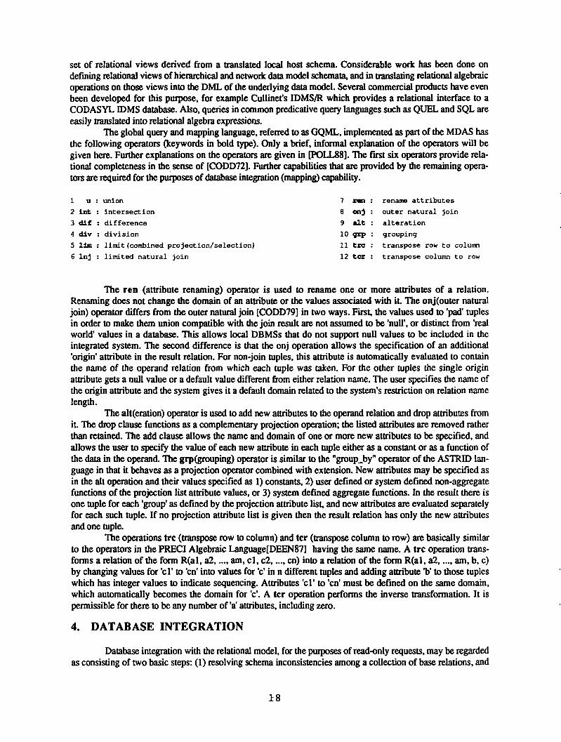
easily translated into relational algebra expressions.The global query and mapping language, referred to as GQML, implemented as part of the MDAS has
the following operators (keywords in bold type). Only a brief, informal explanation of the operators will be
given here. Further explanations on the operators are given in POLLS8]. The first six operators provide rela
tional completeness in the sense of CODD72]. Further capabilities that are provided by the remaining opera
tors are required for the purposes of database integration (mapping) capability.
1 u union 7 r~i renan~ attributes
2 mt : intersection 8 cnj : outer natural join
3 dif : difference 9 alt : alteration
4 div division 10 grp : grouping
5 urn : lirnit(cornbined projection/selection) 11 tra : transpose row to column
6 lnj : limited natural join 12 tcr : transpose column to row
The ren (attribute renaming) operator is used to rename one or more attributes of a relation.
Renaming does not change the domain of an attribute or the values associated with it. The onj(outer natural
join) operator differs from the outer natural join CODD79] in two ways. First, the values used to ‘pad’ tuplesin order to make them union compatible with the join result are not assumed to be ‘null’, or distinct from ‘real
world’ values in a database. This allows local DBMSs that do not support null values to be included in the
integrated system. The second difference is that the onj operation allows the specification of an additional
‘origin’ attribute in the result relation. For non-join tuples, this attribute is automatically evaluated to contain
the name of the operand relation from which each tuple was taken. For the other tuples the single originattribute gets a null value or a default value different from either relation name. The user specifies the name of
the origin attribute and the system gives it a default domain related to the system’s restriction on relation name
length.The alt(eration) operator is used to add new attributes to the operand relation and drop attributes from
it. The drop clause functions as a complementary projection operation; the listed attributes are removed rather
than retained. The add clause allows the name and domain of one or more new attributes to be specified, and
allows the user to specify the value of each new attribute in each tuple either as a constant or as a function of
the data in the operand. The grp(grouping) operator is similar to the “group_by” operator of the ASTRID lan
guage in that it behaves as a projection operator combined with extension. New attributes may be specified as
in the alt operation and their values specified as I) constants, 2) user defined or system defined non-aggregatefunctions of the projection list attribute values, or 3) system defined aggregate functions. in the result there is
one tuple for each ‘group’ as defined by the projection attribute list, and new attributes are evaluated separatelyfor each such tuple. If no projection attribute list is given then the result relation has only the new attributes
and one tuple.The operations trc (transpose row to column) and tcr (transpose column to row) are basically similar
to the operators in the PRECI Algebraic anguageDEEN87] having the same name. A trc operation trans
forms a relation of the form R(al, a2,..., am, ci, c2,
..., cn) into a relation of the form R(al, a2,..., am, b, c)
by changing values for ‘ci’ to ‘cn’ into values for ‘c’ in n different tupies and adding attribute ‘b’ to those tupleswhich has integer values to indicate sequencing. Attributes ‘ci’ to ‘cn’ must be defined on the same domain,
which automatically becomes the domain for ‘c’. A tcr operation performs the inverse transformation. It is
permissible for there to be any number of ‘a’ attributes, including zero.
4. DATABASE INTEGRATION
Database integration with the relational model, for the purposes of read-only requests, may be regardedas consisting of two basic steps: (1) resolving schema inconsistencies among a collection of base relations, and
18
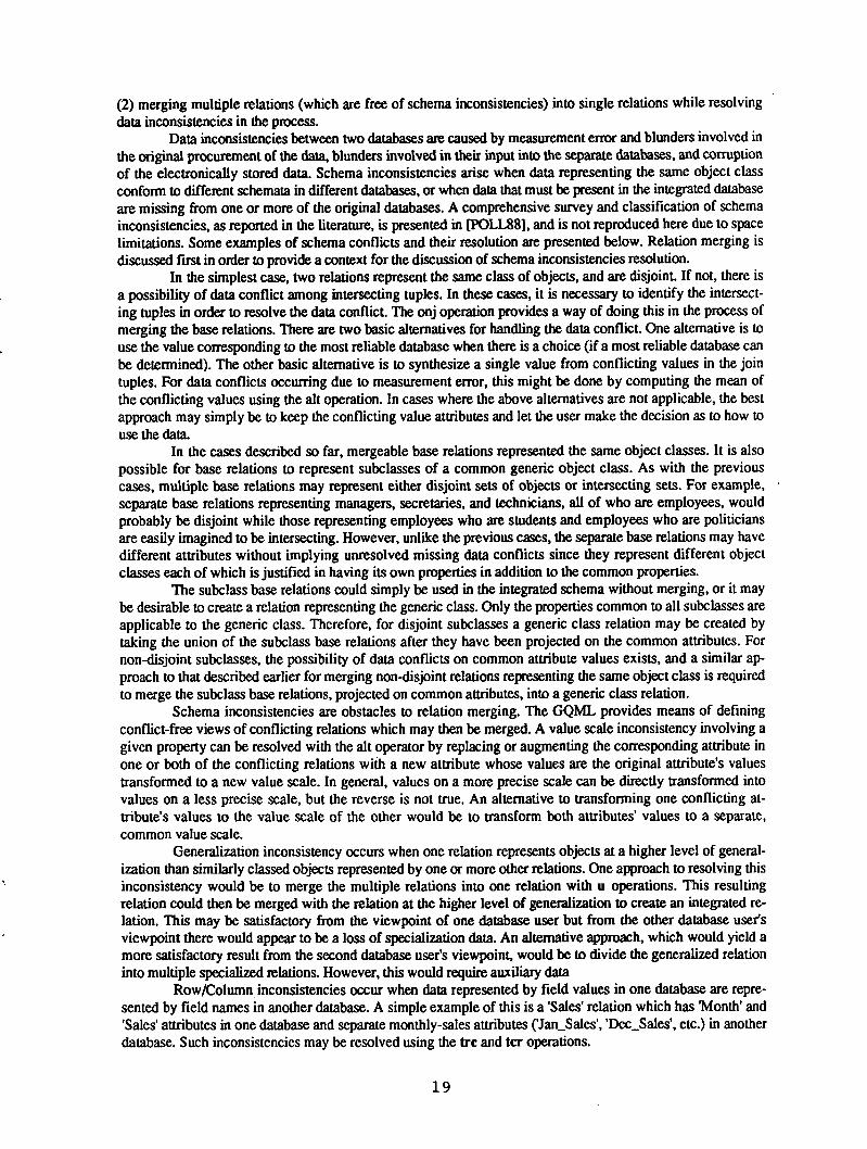
(2) merging multiple relations (which are free of schema inconsistencies) into single relations while resolving
data inconsistencies in the process.
Data inconsistencies between two databases are caused by measurement error and blunders involved in
the original procurement of the data, blunders involved in their input into the separate databases, and corruption
of the electronically stored data. Schema inconsistencies arise when data representing the same object class
conform to different schemata in different databases, or when data that must be present in the integrated database
are missing from one or more of the original databases. A comprehensive survey and classification of schema
inconsistencies, as reported in the literature, is presented in POLL88], and is not reproduced here due to space
limitations. Some examples of schema conflicts and their resolution are presented below. Relation merging is
discussed first in order to provide a context for the discussion of schema inconsistencies resolution.
In the simplest case, two relations represent the same class of objects, and are disjoint. If not, there is
a possibility of data conflict among intersecting tuples. In these cases, it is necessary to identify the intersect
ing tuples in order to resolve the data conflict. The onj operation provides a way of doing this in the process of
merging the base relations. There are two basic alternatives for handling the data conflict. One alternative is to
use the value corresponding to the most reliable database when there is a choice (if a most reliable database can
be determined). The other basic alternative is to synthesize a single value from conflicting values in the join
tuples. For data conflicts occurring due to measurement error, this might be done by computing the mean of
the conflicting values using the alt operation. In cases where the above alternatives are not applicable, the best
approach may simply be to keep the conflicting value attributes and let the user make the decision as to how to
use the data.
In the cases described so far, mergeable base relations represented the same object classes. It is also
possible for base relations to represent subclasses of a common generic object class. As with the previous
cases, multiple base relations may represent either disjoint sets of objects or intersecting sets. For example,
separate base relations representing managers, secretaries, and technicians, all of who are employees, would
probably be disjoint while those representing employees who are students and employees who are politicians
are easily imagined to be intersecting. However, unlike the previous cases, the separate base relations may have
different attributes without implying unresolved missing data conflicts since they represent different objectclasses each of which is justified in having its own properties in addition to the common properties.
The subclass base relations could simply be used in the integrated schema without merging, or it may
be desirable to create a relation representing the generic class. Only the properties common to all subclasses are
applicable to the generic class. Therefore, for disjoint subclasses a generic class relation may be created by
taking the union of the subclass base relations after they have been projected on the common attributes. For
non-disjoint subclasses, the possibility of data conflicts on common attribute values exists, and a similar ap
proach to that described earlier for merging non-disjoint relations representing the same object class is requiredto merge the subclass base relations, projected on common attributes, into a generic class relation.
Schema inconsistencies are obstacles to relation merging. The GQML provides means of definingconflict-free views of conflicting relations which may then be merged. A value scale inconsistency involving a
given property can be resolved with the alt operator by replacing or augmenting the corresponding attribute in
one or both of the conflicting relations with a new attribute whose values are the original attribute’s values
transformed to a new value scale. In general, values on a more precise scale can be directly transformed into
values on a less precise scale, but the reverse is not true. An alternative to transforming one conflicting at
tribute’s values to the value scale of the other would be to transform both attributes’ values to a separate,
common value scale.
Generalization inconsistency occurs when one relation represents objects at a higher level of generalization than similarly classed objects represented by one or more other relations. One approach to resolving this
inconsistency would be to merge the multiple relations into one relation with u operations. This resultingrelation could then be merged with the relation at the higher level of generalization to create an integrated re
lation. This may be satisfactory from the viewpoint of one database user but from the other database user’s
viewpoint there would appear to be a loss of specialization data. An alternative approach, which would yield a
more satisfactory result from the second database user’s viewpoint, would be to divide the generalized relation
into multiple specialized relations. However, this would require auxiliary data
Rowi~olumn inconsistencies occur when data represented by field values in one database are repre
sented by field names in another database. A simple example of this is a ‘Sales’ relation which has ‘Month’ and
‘Sales’ attributes in one database and separate monthly-sales attributes (‘Jan_Sales’, ‘Dec_Sales’, etc.) in another
database. Such inconsistencies may be resolved using the ire and icr operations.
19

5. QUERY PROCESSING
In designing and implementing the MDAS query processor we assumed that the sites are connected byfast short-haul links, so intersite communication delay does not dominate data processing delay, each site is
capable of supporting any GQML operation and that database statistics would not be available. In the MDAS, a
join on relations residing at different sites is always be executed at the query site. However, schemes for
optimizing these joins require database statistics.
Each site in the HDDBMS has its own unique site designator and its own process (qproc process)
running the query processing algorithm. A OQML query submitted to the qproc process running at a particularsite consists of a result relation name and a GQML expression (possibly nested) on terminal and/or non-ter
minal relations specified at that site with GQML virtual relation definitions and base relation declarations. The
local site is the site where the qproc process is running, and the query Site is the site where the query originatesfrom, and where the results are required. If the query site designator is the same as the local site designator, then
the query is local, otherwise it is remote. Local and remote queries are handled in exactly the same way, except
that the result of a local query remains at the local site while the result of a remote query is sent to the query
site. A detailed description of our query processing algorithm is presented in POLL88]. A brief description is
presented below.
The basic feature of our query processing algorithm is the decomposition of a query on virtual rela
tions at a given site (the query site) into zero or more subqueries that are entirely satisfied by local data (local
subqueries), zero or more subqueries on virtual relations which, according to the locally stored mapping specifications, are not derived from local data (remote subqueries), and a final subquery on the results of the local and
remote subqueries and/or translated local host schema relations. The important thing to note is that local and
remote subqueries can be further processed and executed in parallel. Local and final subqueries are translated into
a form that can be executed by the local DBMS. When a translated subquery is submitted to the local DBMS
the qproc process no longer has any involvement in it except to determine whether or not the execution was
successful. The translated final subquery may be augmented with instructions to the local DBMS to present the
user with options for activities such as viewing the final result, and erasing the result file. If data reformatting
capabilities are an integral part of the local DBMS, it might make sense to also include, in the transformed
final subquery, instructions to convert received global format remote data (the results of remote subqueries) to
local format, rather than to perform the reformatting immediately on receipt of the data.
If there are no remote subqueries, then there will be no local subqueries, and the entire query will be
executed as the final subquery. If there are no local subqueries and only one remote subquery then the result of
that remote subquery would contain the query result data. In this case, the final subquery would be ‘null’ and
would result in the activities that would be appended to any other final subquery upon translation, such as data
reformatting and results display.When a remote subquery is dispatched to a remote site, it is submitted as an ordinary query to the
qproc process at that site (i.e., the receiving qproc process does not need to know that the query is actually a
subquery from another site), which then processes it and returns the results to the dispatching qproc process
site. When processing a remote query the qproc process may itself dispatch further remote subqueries if the lo
cal DBMS is a HDDBMS.
The query decomposition algorithm (decompose_query), described in POLL88], is based on the de
composition of a directed acyclic graph (DAG) of operations representing the query into separate subgraphs
representing the subqueries. The subquenes are described by an internal representation of a DAG of GQML op
erations.
6. SOME IMPLEMENTATION DETAILS AND CONCLUSIONS
The current MDAS prototype integrates two sites, represented by two PCs connected by a null mo
dem. One site has dBase III as its host DBMS, and the other site has KnowledgeMan (KMan). All data pro
cessing, including data file reformatting, is performed by these DBMSs under the direction of the MDAS. The
MDAS provides each site with a relational integrated schema of the local host databases. Users can submit ad
hoc global queries the result of which is a file in the local file format. All MDAS modules were written in the
‘C’ programming language.
20

The user executes a terminal monitor process which requests the result relation name and the GQMLquery text. It is asswned that the remote request server process is executing on the remote systems when a
query is submitted. The global query processor transmits all remote subquenes in a smgle communication ses
sion with the remote request server process.
The result of a user’s query is assembled at the query site. The global query processor instructs the lo
cal host DBMS to offer to display the results at the terminal when the data processing is complete. In contrast,
the result to a remote request is ultimately assembled in a global format ASCII text file (by the local host
DBMS under the instruction of the global query processor) and is then sent back to the query site by the remote
request server.
Since the MDAS processes a remotely submitted query on a local participant schema with much of
the same software that it uses to process a locally submitted query on an integrated schema, a local participantschema is readily supported as a view of the local host schema, defined by GQML operations on the local host
schema relations.
The current design emphasizes practicality over optimization. In particular, the global query process
ing algorithm does not attempt to optimize the degree of parallelism in local query processing and execution. In
fact, a query that can be executed at a single Site (entirely as a ‘final subquery’) will be executed this way, with
no parallel processing at all. Parallelism and optimization would require estimates and comparisons of the delayinvolved in individual operations and global knowledge of the additional mapping operations required to
materialize remote global schema relations. This in turn would increase the complexity and size of the system
considerably. Furthermore, simple local DBMSs of the type that we assumed in our design and incorporated in
our implementation do not maintain the database statistics required for the estimation of the relative execution
times of operations.Extensions to the MDAS prototype are planned. Incorporating additional sites (assuming communi
cations support from network software and hardware) into a MDAS integrated system involves building a new
low-level module to support the mapping level between the local host schema and the translated local host
schema for each additional local DBMS with a previously unsupported data model and query language. The
global schema would also have to be expanded and the integrated schemata for those sites that wish to incorporate the additional data would have to be modified. Few requirements are imposed on local DBMSs and host
schemata, so the MDAS approach is widely applicable in the context of record-oriented data and read-only requests. Integrating the MDAS with a natural language interface is underway. Longer term planned extensions
include the implementation of global and local query optimization techniques proposed in POLL88] which do
not require database statistics or global knowledge of local low-level mappings. Also, the feasibility and desir
ability of accommodating update at different schema levels, and the impact and possible control of update performed directly through local DBMSs will be investigated.
REFERENCES
CARD87J A.F. Cardenas, “Heterogeneous Distributed Database Management the HD-DBMS,” Proceedingsof the IEEE, Vol. 75-5, May 1987, pp. 588-600.
CODD72] E.F. Codd, “Relational Completeness of Database Sublanguages,” in E. Rustin(ed), Data Base
Systems, Prentice-Hall, Englewood Cliffs, New Jersey, (1972), pp. 65-98.
CODD79] E.F. Codd,” Extending the Database Relational Model to Capture More Meaning,” ACM Transac
tions on Database Systems, Vol. 4-4, December 1979, pp.397-434.DEEN87] S.M. Deen, R.R. Amin, and M.C. Taylor, “Data Integration in Distributed Databases,” IEEE
Transactions on Software Engineering, Vol. SEI3-7, July 1987, pp. 860-864.
LAND82] T. Landers and RI. Rosenberg, “An Overview of Multibase,” in HJ. Schneider, ed., Distributed
Databases, North Holland Publishing Company, (1982), pp. 556-579.
POLL88] R. Pollock and B.C. Desai, “The Design and Implementation of a Heterogeneous Distributed
Database Management System Prototype,” CSD-88-08, Concordia University, Montreal, Quebec, (1988).
21

PICTORIAL/VISUAL ACCESS TO
MULTIMEDIA/HETEROGENEOUS DATABASES
Alfonso F. Cardenas
Computer Science Department3731 Boelter Hall
University of California, Los Angeles.Los Angeles, CA 90024
Tel. (213) 825-2660
Abstract
The need is stressed for (1) future-generation generalized pictorial and graph database management; and (2) (a) an
effective and integrated view and (b) high-level pictorial/visual accessing of data residing in a network of different
pictorial and non-pictorial databases. Some highlights and illustrations of our R&D goals, progress and direction
are briefly introduced herein.
1. INTRODUCTION
As we enter the 1990’s, there is a growing number of heterogeneous of databases under a variety of both conven
tional database management systems (DBMSs) and recently emerging pictorial data management systems. The ma
jor thrusts of our research and development effort are to develop the architectural framework, detailed specificationand proof of concepts of advanced system software:
1. To provide future-generation generalized pictorial and graph database management
2. To provide (a) an effective and integrated view and (b) high-level pictorial-oriented or visual-oriented ac
cessing of data residing in a network of different pictorial and non-pictorial databases.
2. PICTORIAL DATA MANAGEMENT
For many years special image data handling systems have been developed to store and retrieve specific types of pictorial data. More recently, however, it has been realized that instead of a one-of-a-kind approach, a generalized pictorial database management system is beuer (much in the same way that today’s DBMSs for record-type data are
preferred in most cases over tailor-made systems to manage a particular type of record).
For pictorial data consisting of clearly delineated objects (such as road maps and physical-wire layouts) that can be
reduced to points and lines, conventional DBMSs can represent the data, and frequently needed pictorial operationscan be rather well supported, although not always directly, by conventional DBMS operations (join, project). Un
fortunately, other pictorial data (vegetation photographs, X-rays) cannot be easily reduced to points and lines be-
cause there is rarely a clear boundary between objects, e.g., between desert and non-desert areas. Thus, convention
al DBMS cannot be used practically to define the data objects. Furthermore, typical operations required by users of
such pictorial data are rarely well supported by the operations of a conventional DBMS CHOC81]. It is this type of
data that is perhaps the most voluminous and the one being collected at the fastest rates. For example, the rates at
which imaging sensors on satellites collect data is astonishing: dozens of megabits per second operating around the
clock for days, months and years.
~2 2

The Pictorial Database Management System (PICDMS) has been designed at UCLA since the mid 1980’s
CHOC85, JOSE88]. It supports data object definition, storage, accessing, and interpretation. The data model pro
posed is the stacked-images database model, illustrated in Figure 1. It shows several types of pictorial data, some of
which is data directly measured by instruments (such as elevation), and other of which is derived, or entered directlyby humans (such as census tracks or any free form sketches). No conventional DBMS is used internally. PICDMS
was built from the ground up with pictorial data management facilities as the major requiremenL A procedureoriented language was initially defined and partially implemented for PICDMS CHOC85]; a QBE-flavoredPICDMS language, PICQUERY JOSE88], has been subsequently also designed to operate at an even higher level.
Joseph outlines the major pictorial data management operations on an entire picture(s) or object(s) within the
picture(s) to be supported by PICQUERY or any other powerful pictorial data accessing language JOSE88J: (1)Image manipulation (rotation, various types of zooming, masking, etc.); (2) pattern recognition (edge detection,
similarity retrieval on the basis of shape or size or any other criteria, etc.); (3) spatial (distance, length, intersection
of objects, union or difference of region objects, etc.); (4) input/output (read, write, update picture or object(s)within the picture).
Example I
English: Identify the points in picture PlC! where missiles with range greater than 5000 miles
and speed greater than 25,000 mph are deployed
PICQUERY:
Picture
1
Object Name Picture
2
Selection Condition
Variable Relation
Operator
Value LogicalOperator
Group
PIC1 MISSILES PIC2 RangeSpeed
.gt.
.gt.
5000
25000
.and. 1
1
The underlying databases actually involve: (a) picture PIC1 with objects that look like missiles and (b) other pictures (PIC2) of known missiles with their non-pictorial information (range, speed, etc.). The non-pictorial informa
tion would actually be in a conventional DBMS, in which all other related non-pictorial information would be held.
Internally, powerful pattern matching facilities would search automatically PIC1 to find any objects that match the
pictures in PIC2 of missiles with the indicated non-pictorial characteristics. This pictorial object recognition and
matching capability plus the integration of pictorial and non-pictorial data is not available in commercial DBMS.
Example 2
English: Retrieve objects in picture P2 similar to objects identified in picture P1. Similarity retrieval operationscan be done on the basis of size, shape, texture, or any other user-defined application dependent basis.
PICQUERY:
Picture 1 Object Name Basis Picture 2 Object Name ObjectType
PIC1 Cl Shape PIC2 P. P.
23

Visual Oriented Model and Query Language
It is our belief that visual query languages will be very attractive and in many cases highly preferred over text-
oriented conventional database query languages and programming languages. CHAN88] outlines visual languages.
Visual languages also avoid one difficulty of text oriented languages: understanding by those who do not read/write
in the particular text language. PIZA89J presents the highly visual data model features and the language that we
propose for querying and specifying spatial integrity constraints in pictorial data bases.
Figure 2 shows a sample of the data model serving as the background. Pictorial and non-pictorial entities or objects
and their attributes are involved. Pictorial or spatial relationships (associations between pictorial objects because of
their relative positions in the picture) and conventional DBMS relationships (e.g. city x ‘receives-money-from’
county y) between objects are involved. The data model visualized by the user conceptually is an extended Entity-
Relationship data model developed to support pictorial and multi-media data management. Underneath the concep
tual layer, multiple pictorial and non-pictorial databases are involved. All this and the stacked-images data model
features illustrated in Figure 1 constitute major features of our logical data model.
Figure 3 provides an entirely visual constraint specification for “automobiles and people (denoted as* in the picture)
can not be in a crosswalk simultaneously”. Entities and spatial relationships addressed in the integrity constraint are
highlighted. Note that in this example we have avoided entirely the use of any text language.
3. GRAPH DATA BASE MODEL AND QUERY LANGUAGE
New database support is proposed for an important class of data objects: those that may be defined as graphs (made
up of nodes and edges). Examples include instances of network layouts, from office procedures diagrams to com
puter networks to telephone networks to road networks. Figure 4 contains some specific examples of graph-type
data objects from the information systems design and development (software engineering) area: E-R diagram in the
E-R database model, process and data flow diagrams, and SADT diagrams of the structured analysis and design
technique. These examples constitute a collection of seemingly heterogeneous databases which need to be managed
and accessed as “one” database. There are many applications where the data objects can be more adequately
managed as graphs; most importantly, from the logical user view point and the required operations on such data ob
jects, they are graphs. A “graph data model” (GDM) and a data manipulation language for the data represented in
the GDM has been designed and proposed CARD9O, WANG9O].
Graph data objects are not well handled by existing database management systems, nor pictorial DBMS (including
PICDMS). This inadequacy of DBMS is due primarily to the lack of fixed structure in graph-type data objects even
among instances of the same data class. The 0DM provides a natural representation for graph-type data objects.
This natural representation in turn makes query and manipulation of graph-type data objects simple and natural to
the average end user. For a user, it is undoubtedly more convenient, for example, to add or delete (a) an entity
and/or relationship in an E-R model or (b) a function (shown as a box and its connecting flows in an SADT di
agram), directly on the graph model rather than on the indirect representation of such graphs expressed in relational
tables and using a relational language. In particular, the GDM eliminates the need for recursive queries which are
inherently associated with representing graph-type data objects in a conventional data model such as the relational
model.
5. CONCLUSION
Our R&D and actual experiences in data management lead to envisioning the following needs and directions:
• New pictorial DBMS for generalized pictorial/image data management
• New graph DBMS for generalized graph data management
• Conventional DBMS possibly extended for pictorial data but only with well delineated
24

geographical boundaries (e.g., street maps)
• More intelligent data dictionary/directory systems capable of dealing with pictorial,
graph and conventional record-type data
• A “multi-media DBMS” consisting of conventional DBMS, pictorial DBMS and graph DBMS,
with a new software layer on top (including a very intelligent data dictionary/directory)
providing a single integrated DBMS environment and language for users
• More intelligent visual oriented languages for pictorial and multi-media database management
These are the overall needs and challenges addressed by our R&D effort In short integration of a variety of data
bases of the above types, such that from the user point they appear as one integrated database, and such that they
may be accessed via a common integrated language capable of referring to any combination of heterogeneous data
bases. The architecture, specification, prototype implementation of key elements, and proof of concept of such an
integration capability have been our goals. We have progressed a great deal and shown the feasibility of achieving
these goals in various references.
REFERENCES
CARD9O] Cardenas, A.F. and G. Wang, “Multimedia/Heterogeneous Database Management: Graph Data,”
IEEE Office Knowledge Engineering, 1990.
CHAN88) Chang, S.K., “Visual Languages: A Tutorial and Survey,” IEEE Software, Vol. 4, No. 1, January
1988, pp. 29-39.
CHOC81J Chock, M., A.F. Cardenas, A. Klinger, “Manipulating Data Structures in Pictorial Information
Systems,” IEEE Computer, 14-11:43-50, November 1981.
CHOC85J Chock, M., A.F. Cardenas, A. Klinger, “Data Base Structure and Manipulation Capabilities of a
Picture Data Base Management System (PICDMS),” IEEE Transactions on Pattern Analysis
and Machine Intelligence, Vol. PAIvII-6, No. 4, July 1985, pp. 484-492.
JOSE88] Joseph, T., A.F. Cardenas, “PICQUERY: A High Level Query Language for Pictorial Data
Base Management,” IEEE Transactions on Software Engineering, special issue on Image Data
Management, Vol. 14, No. 5, May 1988, pp. 630-638.
PIZA89] Pizano, A., A. Klinger and A.F. Cardenas, “Specification of Integrity Constraints in Pictorial
Databases,” IEEE Computer, December 1989, pp. 59-7 1.
WANG9O] Wang, G. and A.F. Cardenas, “Representation and Manipulation of Graph Data Objects,” to be
submitted for publication in 1990.
25
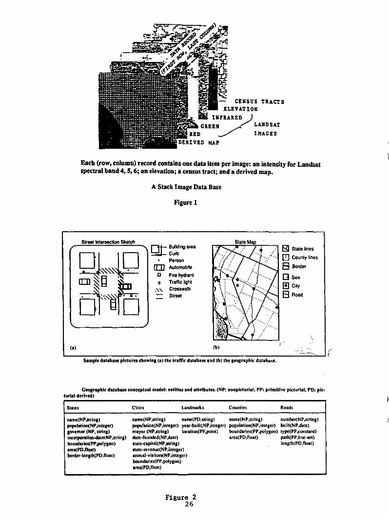
Each (row, column) record contains one data item per image: an intensity for Landsat
spectral band 4, 5,6; an elevation; a census tract; and a derived map.
A Stack Image Data Base
Figure 1
CENSUS TRACTS
ELEVATION
INFRARED )
GREEN ~.-‘ LANDSAT
IMAGES
Street Intersection Sketch
F.I
i• ir~n °1
~J Building area
Curb
• Person
tEti Automobile
o Fire hydrant
o Traffic light
•\~ Crosswalk—
Street
State lines
El County lines
B Border
o Sea
j~ City
O Road
(a) (b)
(Sample database pictures showing (a) the traffic database and (b) the geographic database.
Geographic database conceptual model: entities and attributes. (NP: nonplctorial, PP: prImitive pictorial, PD: plc.tonal derived)
States Cities Landmarks Counties Roads
name(NP.string) name(NP,string) name(PD,string) name(NP.string) number(NP,string)
poputation(NP,integer) population(NP.integcr) year-built(NP,intcger) population(NP.inleger) built(NP.date)
governor (NP. string) mayor (NP.string) location(PP.point) boundaries(PP.polygon) type(PP.conslant)
incorporation.date(NP.string) date.founded(NP.date) area(PD,float) path(PP.Iine-set)
boundsries(PP.polygon) statc.capital(NP.itnng) length(PD.float)
atea(PD.float) state.revenue(NP.integer)
boider-ICngth(PD.float) winual-visitors(NP,integer)boundaries(PP.polygon)area(PD.float)
Figure 2
26

Figure 3
Example graph data objects
Figure 4
27
**
Con.tralnt dracilption uilng entity highlighting: Automobile. and
people Caonot be in a croiwalk simultaneously.
A Taxonomy for Classifying Commercial Approachesto Information Integration in Heterogeneous Environments
Amar Gupta and Stuart E. Madnick
Sloan School of ManagementMassachusetts Institute of Technology
Telephone: (617) 253-8906 and (617) 253—6671
E-Mail: [email protected] and [email protected]
Room E40—265, One Amherst Street, Cambridge, MA 02139
ABSTRACT
Commercial systems and research prototypes for integration of
heterogeneous information systems can be broadly classified into
four major categories depending on the level of changes requiredto existing systems and the type of capabilities provided. Eightcurrent systems representing the four categories are compared with
respect to data models, global schemas, query processing, and
transaction management.
INTRODUCTION
\~Ongoing efforts at MIT’S Sloan School of Management in the
field of connectivity in heterogeneous environments are described
in a companion paper in this special issue. As a part of these
efforts, many commercial systems and research prototypes were
studied, both to determine areas characterized by gaps in
technology, as well as to avoid “reinventing the wheel” in areas
where other researchers and designers have achieved success.
Based on information collected from various sources, over 100
potential candidate systems were identified. Initial scrutinyreduced this number to 24 that actually provided significantcapabilities. For each of these 24 systems, the respectivecompanies completed a questionnaire composed of 21 items.
Presently, the accuracy of these responses is being verified, and
the answers are being normalized to use common terminology.Page limitations make it impossible to reproduce all the
information gathered in this paper. We cover only the most
important issues using a representative set of eight commercial
approaches. Additional comparative information is available in
(BHAL87], REDD88], GUPT89aJ, and GUPT9Ob].
TAXONOMY
There are many potential schemes for categorizing approachesto integrating heterogeneous systems. We have developed a taxonomyfocusing on the business and organizational impacts. This taxonomyclassifies approaches into four categories: (i) Unintrusive
Integration; (ii) Intrusive Integration; (iii) Interfacing with
Controlled Redundancy; and (iv) Interfacing with Transaction
Transfer.
Unintrusive Integration techniques do not demand that specificmodules be resident in or added to each participating database
system. This is based on the premise that existing information
systems cannot, and should not, be tampered with.
Intrusive Integration requires either some modification of
existing information systems or the placement of specific modules
28

within these systems. These modules are typically utilized to
perform network services, to store information on the location of
specific files, or to initiate secondary processes in case some
resources are inoperational or too slow in responding to requests.
Interfacing with Controlled Redundancy focuses on strategiesfor getting the necessary pieces of information on a “just—in—time” basis, by making assumptions about the perceived needs of the
user. No effort is made to create a global conceptual schema.
Instead, pieces of data are prestaged and systematically assembled
together over time to provide the final unified answer. As partof this process, data are selectively replicated.
Interfacing with Transaction Transfer constitutes the simplesttechnique for managing transactions in a heterogeneous environment.
Instead of creating a global schema or prestaging data to meet
anticipated needs, information is accessed from a relatively small
number of systems in response to the user query. Queries and
updates are replicated and transmitted to individual systems for
processing by them.
Of the 24 systems analyzed, more than half of them belongedto the category of Intrusive Integration. Although many systemsdo not fall exclusively into one category, the table shows the
closest category for eight systems.
CONCLUSION
Information in the table shows the diversity in the strategiesadopted by various design teams for developing commercial productsand approaches. Not surprisingly, in virtually all cases, the
global query processing capabilities are more sophisticated than
the global update processing capabilities. In fact, the latter
capabilities are unavailable in several cases.
Although not shown in the table (because of space
constraints), a number of commercially available approaches can be
hosted on systems of dissimilar architectures. Features which were
considered advanced on research prototypes just two years ago are
now available on commercial systems.
REFERENCES
BHAL87J Bhalla, S., Prasad, B.E., Gupta, A. and Madnick,
S.E., “A Technical Comparison of Distributed Heterogeneous Database
Management Systems,” in (GUPT87], pp. 161—218.
(GUPT87) Gupta, A., and Madnick, S.E. (editors), IntegratingDistributed Homogeneous and Heterogeneous Databases: PrototypesMIT, Cambridge, MA, 1987. (NTIS/DTIC Accession #A195852).
(GUPT89a) Gupta, A. (editor), Integration of Information
Systems: Bridging Heterogeneous Databases IEEE Press, New York,1989.
(GUPT9Ob] Gupta, A. Madnick, S.E., Poulsen, C., and Wingfield,T., An Architectural Comparison of Contemporary Approaches and
Products for Integrating Heteroaeneous Information Systems IFSRC
working Paper #110—89, Sloan School of Management, 1989.
REDD8BI Reddy, M.P., Prasad, B.E., and Reddy, PG., “QueryProcessing in Heterogeneous Distributed Database ManagementSystems,” in (GUPT89a], pp. 264—277.
29

BBN SYSTEMS &
TECHNOLOGIES:
CRONUS
Category
Unintrusive
Integration (UI)
Unintrusive
Integration (UI)
Unintrusive
Integration (UI)
Intrusive
Integration (II)
Local Data
Models
Supported
Object-orientedand Relational.
Relational,Network/Codasyl,and Hierarchical.
Relational and
Network. Also,supports objects in
files. Qualification to locate
files is done on an
structured relation
that contains the
file name. Retrieve
process and displayprocess are
specific to objecttype.
Relational and
Network.
Global Data
ManipulationLanguage
A subset of SQL. Neutral Data
ManipulationLanguage (NDML), a
SQL based query
language. NDML
can be embedded in
Cobol, Fortran, and
C.
SQL.
~
SQL.
Global Data
Model
Object oriented. A 3-schema
architecture with
conceptual schema
stored in IDEF1X,and ER based
modeling method.
Relational. Relational.
CONTROL DATA CORP: DATA INTEGRATION INC:
CDM*PLUS MERMAID
CINCOM:
SUPRA
0

GUPTA TECHNOLOGIES
INC:
SQL SYSTEM (II)
ORACLE CORP:
ORACLE
TRW: METAPHOR:
TRW DATA INTEGRATION DATA INTERPRETATION
ENGINE SYSTEM
Category.
Intrusive
Integration (II)
Intrusive
Integration (II)Interfacing with
Controlled
Redundancy (ICR)
Interfacing with
Transaction
Transfer (ITT)
Local Data
Models
Supported
Relational
(extended).
~
Relational. Hierarchial,Relational, and
Network.
Relational and
relational inter-
face. Interface to
other non-relation—
al DBMS facilitated
through TTY, 3270,and 3780 emulators
that are invoked
through simplemouse point-and-click actions bythe user.
Global Data
ManipulationLanguage
SQL with enhance-
inents (SQL-Talk),pre—compiler for
ANSI COBOL, and
application programinterfaces for C.
SQL. None required. User points-andclicks at same
iconic interface
across all
supported relation—
al DBMS. SQL auto
matically produced.Metaphor gatewayservers convert SQL
as required for
platform.
Global Data
Model
Relational
(extended).
Relational. ECR. Also allows
multiple globalschemata.
Relational.
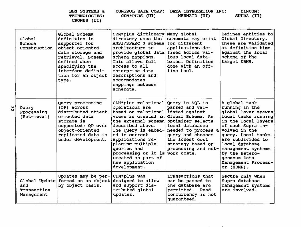
BBN SYSTEMS &
TECHNOLOGIES:
CRONUS (UI)
CONTROL DATA CORP: DATA INTEGRATION INC:
CDM*PLUS (UI) MERMAID (UI)
CINCOM:
SUPRA (II)
Global
Schema
Construction
QueryProcessing(Retrieval)
Global Schema
definition is
supported for
obj ect—orienteddata storage and
retrieval. Schema
defined when
specifying the
interface defini
tion for an objecttype.
Query processing(QP) across
distributed object-oriented data
storage is
supported; QP over
obj ect-orientedreplicated data is
under development.
CDM*plus dictionarydirectory uses the
ANSI/SPARC 3 schema
architecture to
provide global data
schema mappings.This allows full
access to all
enterprise data
descriptions and
accommodates
mappings between
schemata.
CDM*plus relational
operations are
based on relational
views as created in
the external schema
described above.
The query is embed
ed in current
applications re
placing multiplequeries and
processing or it is
created as part of
new applicationdevelopment.
Many globalschemata may exist
for different
applications de
fined across var
ious local data
bases. Definition
done with an off-
line tool.
Query in SQL is
parsed and val
idated againstGlobal Schema. An
optimizer selects
local databases
needed to process a
query and chooses
the lowest cost
strategy based on
processing and net
work costs.
Defines entities to
Global Directory.These are validated
at definition time
against the local
schema of the
target DBMS.
A global task
running in the
global layer spawnslocal tasks runningin the local layersof each Supra in
volved in the
query. Local tasks
are subdivided to
local database
management systemsby the Hetero
geneous Data
Management Process
or (HDMP).
t’J
Updates may be per- CDM*plus was Transactions that Secure only when
Global Update formed on an object designed to allow can be passed to Supra database
and by object basis. and support dis— one database are management systemsTransaction tributed global permitted. Read are involved.
Management updates. concurrency
guaranteed.
is not

GUPTA TECHNOLOGIES
INC:
SQL SYSTEM (II)
ORACLE CORP:
ORACLE (II)
TRW: METAPHOR:
TRW DATA INTEGRATION DATA INTERPRETATION
ENGINE (ICR) SYSTEM (ITT)
Global
Schema
Constructio~
QueryProcessing(Retrieval)
Supports full
Relational catalog.Several tools for
definition of data
base design are
available. (SQLBase, SQL Windows,SQL Talk, and SQL
Network).
Full SQL supportfor queries from
various query tools
(SQL-Talk, Windows-
Talk, Express Win
dows, APIs, SQL-
Windows, etc.).
Imported database
schemata converted
into relational
format may be
further analyzed to
ensure proper
naming conventions,dependencies and
data definitions.
No global schema
exists or is
considered neces
sary by the vendor.
Once data are un—
ported from the
non—Oracle based
databases, queriesmay be performedvia the SQL language. Direct query
ing of non-Oracle
based systems, be
sides those runningDB2 or DBase III,is not permitted at
this time.
A front end tool
called the
Integration Advisor
allows the inter
active construction
of global integrating schema.
A local database
SQL query can be
processed againsta remote IMS data
base (retrievalonly).
Local schemata of
one or more data
bases are graphically depicted for
the user. If a. particular applicationneeds to aggregatedata across two or
more physical data
bases, Metaphor’sobject oriented
developmentenvironment can be
used.
A query is performed by point-and-clicking at objectspresented as a
logical view tai
lored for the
specific end user.
End user menus,
browse lists, and
computed fields are
presented in a sim
ilar manner. SQL
queries are auto
matically generatedby the DIS tool set
Currently supports Offers data and Automatic updates Not supportedGlobal Update multiple databases referential integ- are permitted and directly.and and multiple rity for data con- a cooperativeTransaction cursors per trans— currency. access framework
Management action. SQL Host
must reside on host
computer and SQLRouter on each PC.
based on “owner-
ship” is utilized.

Mainframe DBMS Connectivity via a
General Client/Server Interface
Wayne V. Duquaine, Member, IEEE
do Sybase, Inc
6475 Christie Avenue
Emeiyville, CA 94608
415-596-3500
Abstract - This paper reports on the integration of a general purpose
Client/Server Interface (CSI) into a mainframe online transaction processing(OLTP) environment. The client/server paradigm provides a powerful means
to effectively create distributed, heterogenous database and transaction
processing environments. The CSI implementation described in this paper
allows access to both relational and non-relational databases, as well as access
to other data sources and/or applications present in high-end mainframe
OLTP environments.
Index Terms - Database, client/server model, transaction processing, remote
procedure call, distributed processing, cooperative processing.
I. Introduction
With the confluence of local area networks providing cheap high bandwidth
interconnection, microprocessor and RISC technologies providing high-end personal
computers and workstations, and sophisticated operating systems such as UNIX, MACH, or
OS/2 running on such computers, decentralized systems have become an organizational fact
of life. The rapidly falling price of such systems has resulted in wide deployment of them.
High-end microprocessors (such as the Intel 80386 and 80486) and their associated high-
speed backplanes (such as Microchannel and EISA) have resulted in systems performancethat rival the mainframes of the previous decade (e.g. the IBM 370/168 and 3033
mainframes). However, the methods of exchanging data between such powerfulworkstations and their mainframe counterparts have seriously lagged the gains in
hardware. High-end workstation-based server systems with 3033-like mainframe power are
typically reduced to interacting with larger mainframes using either dumb terminal
emulation (e.g. 3270 or tn3270) or simplistic file transfer schemes (e.g. RJE or FTP). This
seriously restricts the range of functions and the timeliness of the information that is
exchanged between these systems.
This paper discusses a significant method to overcome these restrictions, by utilizing a
general client/server model between workstations and mainframes. This method extends
the Client/Server model into the IBM mainframe environment. It marries the strengths of
the client/server paradigm with the strengths of IBM’s mainframe OLTP monitors and
databases. The solution models the concepts described by ray1] and pector2], as well as
concepts embodied in the SUN/UNIX RPC model 3]. The architecture not only allows generalclient/server interoperability between workstations and mainframes, but also allows
mainframe to mainframe, as well as mainframe to workstation interoperability. This
architecture has been implemented in the Sybase Open Gateway/CICS and Open GatewaylDB2 products.
The client/server model Consists of a set of clients and servers, interconnected by a
network, which Cooperate for the purpose of processing work in the form of database
accesses, file access, transaction scheduling, and so forth. In the client/server model, each
server provides a service to the clients of the system. A client requests a service by sendinga request message to the corresponding server. The server performs the requested service
34

and then returns one or more reply messages to the requesting client. In the Sybase server
environment, a set of functions called DB-Library, provides the standard interface for
passing a client’s SQL requests or RPC procedure calls to a server. SQL pre-compilers mayalso be used, that allow “embedded SQL” statements to be converted into DB-Library calls. DB
Library provides the underlying message/datastream processing and networking needed to
communicate with a server.
A client/server model provides the following primary advantages:
• distribution of work across multiple platforms in an enterprise: applications can be
decomposed, allowing the client end to focus on analysis and presentation of results, while
the server end can focus on providing high-speed servicing of results and management of
large amounts of data.
• decentralization: because no single mainframe can meet all the computing needs of a
large organization, mainframe workloads have by necessity been split up among multiplesystems. The CS! model provides an ordered, structured way to decentralize and distribute
work among homogeneous and hetergenous systems.
• improved cost/performance benefits: CPU intensive work can be shifted to the clients
where the MIPs are often cheaper. In addition, specialized databases or departmentalspecific data can be moved down to powerful workstation-based data servers, where both
the MIPs and disk storage costs are cheaper. Conversely, if a database grows to the pointthat it overwhelms the capability of a workstation-based server, the data can be uploaded to
a more powerful mainframe. Because of the transparency provided by the CS! model, the
client applications and users are not affected by such a move.
integration of pre-existing systems: an RPC-based client/server model allows data
from existing systems to be accessed, by using RPCs to invoke transactions that operate
against the existing data.
• access to non-database resources: the client/server model is not just limited to database
servers. Production CS! applications have been built that access real-time data feeds such as
Dow Jones stock quotes, or real-time in-memory data structures for manufacturing process-control, or even interactive data exchange with spreadsheets. Each of these resources is
operating as a “server”, with the relevant data arguments being supplied on the RPC call
from the client.
A robust client/server environment requires the following underpinnings:
(1) a peer-to-peer architecture, so that work can be easily moved around the network as
new nodes are added, or as new data servers are added. Master-slave architectures inhibit
the ability to easily access and/or re-deploy resources as needed.
(2) a well defined set of messages with which to exchange requests and replies between
clients and servers.
(3) remote procedure call (RPC) support, so that clients (or other servers) can invoke
transactions running on other nodes, without having to know the names of (database)tables or fields on the remote system. This allows integration of pre-existing (non-relational) data sources, and provides an efficient means to invoke pre-compiled, pre-boundSQL programs (e.g. “static SQL” support for DB 2). By encapsulating data requests into RPC
calls, the client applications are decoupled from the contents of the remote node’s data
structures. This allows the remote server to have better site autonomy and control over its
data, e.g. an MIS department can enforce integrity and authority constraints over its
mainframe data by assuring that only its transaction programs (invoked as RPCs) alter the
data.
35

II. Mainframe OLTP Environment
In the IBM mainframe environment, the most popular relational database system is IBM’s
DB 2. DB 2 is a high-end, ANSI SQL compliant database system, capable of processinghundreds of database transactions per second. DB 2 by itself does not normally have any
built-in communications support. Instead, it relies upon a communications/transaction
monitor, such as IBM’s Customer Information Control System (CICS) or the Information
Management System-Data Communications product (IMS-DC) to perform communications
management and other OLTP functions. Of the two IBM communications/transaction
monitors, CICS is the more popular.
CICS provides OLTP monitor and access functions not only for DB 2 relational databases, but
for a number of other databases that operate in the mainframe world, including IDMS (a
CODASYL style database system) and IMS-DL/l (a hierarchial database system), as well as
providing transaction-based access to other data sources such as VSAM (“flat files”) and FIFO
based message queues. CICS, with a base of almost 30,000 licenses, is installed in nearly 90%
of all large IBM mainframe shops, with over 55% of all mainframe attached terminals
connected into CICS. CICS provides several rudimentary client/server-like functions
between homogenous CICS systems (called “function-shipping”) and has been a leader in
distributed applications in the IBM mainframe world. It was for these reasons that CICS was
chosen as the initial mainframe OLTP environment into which a heterogenousclient/server environment was targeted.
Providing heterogenous client/server capability for such a mainframe OLTP environment
encompassed solving the following technical issues:
(1) Open applications programming interface (API) supporting both client and server
functions
(2) RPC support
(3) Common datastream, including data translation
(4) Gateway support between IBM’s SNA and and the workstation world’s TCP/IP protocols.
III. Technical Aspects of the Solution
All CICS transaction programs access CS! services through an open high level call
interface The interface provides facilities for Server transaction programs to accept
requests from clients, setup and describe the reply columns, and to send the reply data
(rows and/or return parameters). Client transaction programs have facilities to call RPCs
on other mainframes or SQL servers to perform operations on remote objects (databases,
queues, flat files), and receive the reply results (rows and/or return parameters) from the
server system. The detailed communications I/O (e.g. LU 6.2 send/receive calls, etc) are
automatically performed by the “CS! library”, relieving the application programmer from
such details. In addition, because it is a high-level call interface, the details of the
underlying datastream are hidden from the programmer, allowing the programmer to
concentrate on the business application, rather than datastream or communication aspects.
The call-level interface follows standard (OS/370) calling conventions, and hence fits into
the CALL structure of conventional 3GL and 4GL languages used on the mainframe. The call
interface consists of a stub that is link-edited to the CICS transaction program. This stub
logic calls the common “CS! library” that is shared by all CICS transaction programs
running in the CICS address (process) space. An overall diagram depicting the main
components of the mainframe CS! implementation is shown Figure 1.
Both Sybase and customer-written Server applications utilize the CS! library. For example,the Sybase Open Gateway DB 2 product provides general purpose gateway capability
36
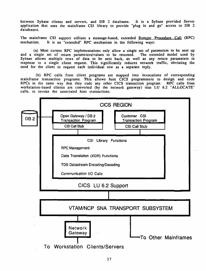
between Sybase clients and servers, and DB 2 databases. it is a Sybase provided Server
application that uses the mainframe CS! library to provide “plug in and go” access to DB 2
databases.
The mainframe CS! support utilizes a message-based, extended Remote Procedure Call (RPC)mechanism. It is an “extended” RPC mechanism in the following ways:
(a) Most current RPC implementations only allow a single set of parameters to be sent upand a single set of return parameters/values to be returned. The extended model used bySybase allows multiple rows of data to be sent back, as well as any return parameters in
response to a single client request. This significantly reduces network traffic, obviating the
need for the client to request each individual row as a separate reply.
(b) RPC calls from client programs are mapped into invocations of correspondingmainframe transaction programs. This allows host CICS programmers to design and code
RPCs in the same way that they code any other CICS transaction program. RPC calls from
workstation-based clients are converted (by the network gateway) into LU 6.2 “ALLOCATE”
calls, to invoke the associated host transactions.
CSI Call Stub CSI Call Stub
VTAM/NCP SNA TRANSPORT SUBSYSTEM
Network
Gateway___
To Workstation Clients/Servers
GIGS REGION
Open Gateway / DB 2
Transaction Proaram
Customer CS)
Transaction Proaram
CSI Library Functions
RPC Management
Data Translation (XDR) Functions
lOS Datastream Encoding/Decoding
Communication I/O Calls
GIGS LU 6.2 Support
To Other Mainframes
37

The messages exchanged between the clients and server are encoded in a c o m m o n
application layer datastream called the Tabular Datastream ( TDS is a self-describingdatastream, and is used in existing Sybase client/server systems, including the mainframe
CSI component. For client requests, it delineates SQL text for “dynamic SQL” operations, and
it describes RPC parameters (length, data type, value) for RPC operations. For Server
replies, TDS supplies column descriptions (length, type, name, etc), row data values, return
parameters, and error and status messages. The encoding of TDS is similar to the proposedISO-RDA datastream, consisting of a data type token, length, and data value.
Data translation support (sometimes referred to as XDR support) is built into the TDS layer.At the beginning of the client request, XDR information is sent, describing the type of
client (little endian or big endian, ASCII or EBCDIC based, etc). This XDR information is
subsequently used by the Server’s TDS component to process the incoming SQL text or RPC
parameters, performing any needed data translations. Similarly, the XDR information is
used when results are sent back to the requesting client.
Connection of (non-SNA based) workstation clients to CICS is through a network gatewaythat converts from TCP/IP transport protocols into SNA LU 6.2 protocols. The network
gateway appears to the workstation-based clients to be another (SQL) Server. The network
gateway exists as a software process that runs on one (or more) of the customer’s
workstations. Attachment from a gateway workstation to the mainframe can be either
SDLC, Token-Ring, or X.25. LU 6.2 was chosen as the protocol of choice for mainframe
attachment for the following reasons:
(a) LU 6.2 is a robust peer-to-peer protocol 4], allowing bi-directional invocation and
data transfer from either workstation-based applications or host-based applications. It does
not suffer from the performance and functional deficiencies found in master/slaveterminal oriented protocols (such as 3270 protocols).
(b) LU 6.2 has been designated by IBM to be the backbone of its SAA and cooperativeprocessing strategies 5]. By adhering to such a significant standard, customer investments
are preserved.
(c) LU 6.2 and its derivative “Intersystems Coupling” (ISC) facilities are frequently used
for workload sharing between mainframes. By using LU 6.2, mainframe CS! applicationscan utilize existing communications facilities when CSI servers are located on other
mainframes in the enterprise.
IV. Unique Aspects of the Solution
There are three unique aspects to the described CS! implementation that distinguish it from
other heterogenous database access solutions: an open API with RPC support, client
facilities at the host, and concurrent access to multiple, different data sources within the
same server application.
Current database gateways tend to be closed, fixed function systems. Virtually all of them
provide support for only “dynamic SQL” command requests (i.e. the shipment of ANSI SQLcommand strings between different vendor’s DBMSes). Dynamic SQL requests tend to be
quite expensive to support, requiring the request to be parsed, bound, and finally executed
each time a new client SQL request is sent to the mainframe’s DB 2 database. By providing a
callable CSI API, frequently executed DB 2 requests can be turned into “static SQL” pre
compiled and pre-bound transaction programs, invoked as RPCs with parameters. Static SQL
requests typically can be executed in 1/3 to 1/2 the path length of Dynamic SQL requests.This savings is achieved through the use of pre-compilers that parse the SQL request and
bind it to the application plan through offline processing. Static SQL support has a dramatic
impact on DB 2 throughput, and the number of client invoked DB 2 transactions that can be
executed per second. And, as previously mentioned, it provides MIS groups with better site
38

autonomy and control over DB 2 resources. It can also avoid malicious or accidental
destruction of DB 2 data, that could be caused by an authorized end-user issuing an ill-
formed dynamic SQL update or delete.
The mainframe CSI implementation allows Client side access from the Host, i.e. CICS
transactions can operate as clients, requesting data from other servers. Those other servers
can reside on another mainframe system, or they can reside on SQL Servers running on
high-end workstations or mini-computers. This allows data to be dispersed around the
enterprise in a transparent fashion, based on system workloads and cost/performancetradeoffs.
Because mainframe CSI server applications can be customer (or ISV) written transaction
programs, they can access any of the various data resources (DB 2, IDMS, DL/1, VSAM,
Queues) that exist in the CICS environment. This allows mainframe server applications to
concurrently access multiple, different data resources in the same transaction, operate
upon them, and return the synthesized results to the requesting client.
V. Future Directions
The current mainframe CS! implementation does not provide cross-environment two-phasecommit. The IBM mainframe environment’s OLTP monitors (CICS and IMS-DC) provide 2-
phase commit support 6] utilizing “Presumed Nothing” algorithms, an outgrowth of the
original two-phase commit algorithms pioneered by IBM during the mid-1970s. The SybaseSQL Server environment provides two-phase commit capabilities utilizing “Presumed Abort”
algorithms, that were invented during the late 1970s. “Presumed Abort” protocols are
slightly more efficient, and are the most popular form of two-phase commit protocols in use
today. “Presumed Abort” protocols have also been adopted by leading standards such as OSI’s
transaction processing standard (ISO-TP) and X/Open’s transaction processing standard
(XTP). The next phase of CS! development will provide two-phase commit capability across
the two environments, thereby providing guaranteed, transaction-based update capabilityacross heterogenous workstation and mainframe server based systems.
References
1] J. N. Gray, “An Approach to Decentralized Computer Systems,” IEEE Trans. Software Eng.,Vol. SE-12, No. 6, June 1986
2] A. Z. Spector, K. Swedlow, “Guide to the Camelot Distributed Transaction Facility,”0.92(37) edition, Carnegie Mellon University, Pittsburgh, PA., 1988
3] SUN Microsystems, Network Programming Guide (Remote Procedure Call Programming~Part Number 800-1779-10, Revision A, May 1988
4] J. P. Gray, P.J. Hansen, et al, “Advanced Program-to-Program Communication in SNA,”IBM Systems Journal, Vol. 22, No.4, December 1984
5] V. Ahuja, “Common Communications Support in Systems Application Architecture,”IBM Systems Journal, Vol. 27, No. 3, September 1988
6] J.N. Gray, “Notes on Database Operating Systems,” in R. Bayer, R.M. Graham(editors),Lecture Notes in Computer Science. Volume 60: Operating Systems
pp 393-481, Springer-Verlag, 1978. Also available as Technical Report RJ2188,IBM Research Laboratory, San Jose, CA, 1978
-39

INGRES Gateways: Transparent Heterogeneous SQL Access
Dave Simonson Dave BenningfieldPrincipal Member, Technical Staff Senior Member, Technical Staff
Ingres Corporation Ingres Corporation1080 Marina Village Parkway 1080 Marina Village ParkwayAlameda, CA. 94501 Alameda, CA. 94501
(415)748-3421 (415) 748-3245
[email protected] [email protected]
Abstract: The Ingres connectivity products, INGRES/Net, INGRES/Gateways and INGRES/Star, provide the
functionality necessary to access almost any data source, at any location, in any grouping, transparentlyusing SQL. This article describes the concepts and some of the design considerations of these products.
Organizations today have multiple data managers. Studies have shown an average of about 4 DBMS systemsalone in an organization. Few, if any, of these systems are able to share data today other than by exchangingdata extracts. This is rapidly becoming unacceptable to these companies, as their data is an importantcompetitive resource that must be available as a whole.
Accessing this data through one interface is important. A program should not have to be rewritten because
it is moved in the network, because the database manager has changed, because a distributed database is
being used, or because a new release of a data base manager has been installed. Indeed, it should not even
be necessary to relink To provide this single image of an organization’s data, it is necessary to hide from
the programmer any indications that the data is in other than a local relational data manager. This requiresmaking a least the following transparent at the application level:
• Local or remote location of the data
• Processor architecture and character set
• Network protocol
• SQL dialect differences
• Presence of any SQL capability at all
• Release of the DBMS system(s)
• Geographic distribution or lack of it
The INGRES connectivity product line, consisting of INGRES/Net, INGRES/Gateways and INGRES/Star,provides the organization with this seamless, transparent access to all of its data. We’ll look at each of the
three INGRES product line offerings, and see what each contributes to achieving this goal.
INGRES Open SQL
To provide transparent access among data sources using SQL, it is necessary to specify, completely, four
items:
• The SQL dialect (including data types and transaction behavior)
• Error handling and return codes
• Catalog definitions
• Communications
A complete specification of all of these items is required; if any one is missing, the systems can not be fullytransparent to the programmer or the user.
40

There are numerous standards designed to help in these areas, such as the ISO and ANSI SQL standards,the X/Open SQL definition, the work done by the SQL ACCeSS Group and IBM’s SAA. Unfortunately, for one
reason or another, all of these fall short of a complete, practical implementation specification. By studyingthe available SQL implementations, Ingres has developed the Open SQL definition. Open SQL completelyspecifies the programmer interface, so the programmer no longer has a dependency on the source of the
data.
The Open SQL dialect was derived from a study of approximately a dozen SQL DBMS systems. It consists
of the set of SQL that these systems can support, or can be made to support (more about this later). It is not
simple dialect; it contains more functionality than some systems provide through their native interface. The
entire INGRES toolset, some 700,000 lines of code, consisting of a 4GL system, screen painter, X/Windows
system, business graphics, etc. is written using Open SQL. (Incidentally, this makes the whole tool set able
to run on all of the gateways.) Beyond the native SQL capabilities of the particular RDBMS, there are some
proprietary INGRES functionality and performance extensions universally supported as well.
The system handles all of the different error codes generated by the various systems through the Generic
Error codes. The Generic Error set provides for a large granularity mapping of the errors from the DBMS
system into one of a set of about 45 codes. These codes describe the class of the error, but usually don’t
describe the exact error. This granularity was chosen to allow the program to easily make run-time decisions
using the codes, but not to replace the local DBMS error code and message. The local code and messageare supplied in the SQLCA, the standard query status return structure, along with the Generic code so that
the programmer has enough information to debug with, and the program can look at them if it knows the
system it is running against. This philosophy differs from that of the SQL2 SQLSTATE values, in that those
are intended to be the only code returned, with no provision for specific local error information returned in
any portable or transparent manner.
The Standard Catalog definitions provide a similar transparency for the DBMS catalogs. Many applicationslook at the system catalogs, if only to determine what data are available for processing. The Standard
Catalogs provide all of the information required by the INGRES toolset (representative of a complexapplication system) and INGRES/Star (representative of a distributed database manager). This is a supersetof the information provided in the SQL2 Schema Information Tables. The Standard Catalogs are implementedas views on top of the native DBMS systems catalogs, allowing them to be active. (Note that the issue of
their updatability does not arise; system catalogs are not updated by the end-user.) They provide the same
release independence that the Generic Errors do - the views are merely reinstalled on the new level of the
system and continue to provide the same information.
Through the Open SQL dialect, the Generic Errors and the Standard Catalogs, the programmer is givenindependence from the characteristics of the underlying data source.
INGRES Networking
The INGRES networking system is built around GCA, the Global Communications Architecture, which
specifies the set of services and protocols used by the system components to communicate with each other.
It is designed to let the various components transfer SQL commands and data, regardless of the inter
connection mechanism and circumstances. GCA consists of the upper four layers of the OSI basic reference
model: Application, Presentation, Session, and Transport. The Application Layer is part of all processes, and
provides the mechanism for local interprocess communication. The Presentation, Session, and TransportLayers, along with the network protocol specific code, are contained in the Communication Server process.GCA is implemented in three parts.The first part is the application program interface, also known as GCA. This is the interface used to access
the communication services provided by the system. GCA allows the system components to communicate
in terms of unative~ SQL data entities such as rows, descriptors, queries and commands. It also enforces a
clearly defined inter-component application layer protocol that has a fixed set of messages which carry data
objects of well-known structure. Supported operations include association initiation and termination, query
processing, interruption, and transaction management (with one and two-phase commit).
41

The second GCA component is the Name Server. The Name Server resolves a database name and returns
to the client GCA interface the name and returns to the client GCA interface the necessary information,
including authentication information, to establish the database connection, whether local or remote. The
Name Server is always present.The thiixJ part, the Communication Server, provides and manages the facilities required to establish and
maintain a connection between two processes (a client and a server) on two different nodes. The
Communication Server is responsible for recognizing a cross-architecture communication session and
performing the necessary application data transformations to support it. This function is contained within the
transport layer and is transparent to the application layer users of the facility.GCF uses standard proprietary network protocol implementations for data transport, such as DECNet,TCP/IP and SNA. The use of these protocols as a tranport mechanism is hidden in the lower layers of the
GCF system and cannot be seen by the programmer.
Thus the INGRES Networking architecture handles the issues of machine architecture, network protocol andlocation transperancy. The next section covers how the gateways transform Open SQL into the appropriateprocessing at the host data source.
INGRES Gateways
The Ingres Gateways provide the interface between the INGRES Open SQL and GCA interfaces and the
native interfaces of a particular data source. There are currently two different architectures used for gatewayimplementations. Which one is used depends on the capabilities of the underlying data source. For
convenience, the two structures are called Type 2 and Type 3. The Type 1 gateway architecture is obsolete;it will be briefly mentioned at the end of this section.
The INGRES Type 2, or Non-Relational, Gateway is the interface to those data sources that either do not
support SQL or do not support enough SQL functionally to put them into the Type 3, or Relational, category.Examples of these systems are IBM’s IMS, the VMS RMS file system and real-time network data feeds.
Looking at the requirements for a Type 2 gateway shows a lot of processing may be required. The gatewaymust take an arbitrary SQL command and execute it against, in the worst case, a flat file system. The gatewayis thus required to syntax check, parse, optimize (you DO want to use the secondary indexes, don’t you?)and then execute the query. It must access the data out of the datasource, perform any aggregate processing,joins, sorts, etc. and then return the result. Note that this is what a relational database does with the data in
its files or tables.
Having a relational database system to hand, INGRES uses the INGRES DBMS as the gateway for these
Type 2 systems; the Gateway runs as part of the INGRES DBMS server. The interface it presents to the user
is that of Ingres, so that when the user accesses the gateway, the user is actually interfacing with INGRES
itself.
The interface with the DBMS is quite straight-forward. The INGRES system supports 4 file structures for its
own tables: hash, heap, ISAM and BTrees. The gateway is added as a fifth, so that it looks just like another
access method to Ingres. The source of the data now becomes transparent to the rest of the DBMS. This
means that the data operated on has no special restrictions, so it can use all the functionality that is in INGRES
itself. It supports SQL and Quel. It uses the Irigres optimizer to build query plans, and it uses all the information
in the INGRES catalogs to describe the data. The statistical distribution information, used by the cost-based
optimizer, is gathered by the standard INGRES OptimizeDB utility, regardless of the source of the data.
All of these Gateways support update access as well as read. The INGRES permissions system, integrities,rules, data base procedures, all control accesses to the data just as if it were in an INGRES table, with the
same constraints that would be encountered, in that case. Any additional constraints applied by the data
source itself would also, of course, apply (and are beyond the scope of Open SQL).The interface to the data source is the standard application interface: e.g. DL/1 for IMS and RPL5 for VSAM.
No bypassing of the native security system is performed.The gateway itself is implemented as about 18 different exit routines from mainline data management
processing, performing normal file system operations such as position, update, delete, replace, get, put - the
standard operations performed in an access method. Keys and read-ahead requests are processed as
determined by the optimizer.
42
Defining the data to INGRES for the Gateway is about the same as creating a table. Descriptive information
is needed in the INGRES catalogs so that it can be accessed by the optimizer and user applications. The
REGISTER command is used to define the data to the system, populating the proper catalogs as if a new
table were being created. The REGISTER TABLE command defines tables and REGISTER INDEX defines
any secondary indices.
Ingres currently has IMS, VSAM and RMS gateways running at customer sites. The Type 3 Gateway is the
interface to a fully relational DBMS. The implementation is much simpler that the Type 2 gateway, because
the system being interfaced with already is capable of processing SQL. The Type 3 Gateway runs
stand-alone: there isn’t an lngres DBMS required anywhere in the enviroment.
Since the interface provided is that of INGRES, as far as the end user programmer is concerned, this is
INGRES. Au INGRES application written to the Open SQL specification runs without change (including
recompilation or relinking) across any of the gateways.The majority of the work performed by the gateway involves scanning the input text of the SQL statement
types (e.g., CREATE TABLE) that may need syntax changes to execute properly at the underlying DBMS,and substituting the appropriate ‘local’ syntax. On occasion, datatype coercions will also be done. On output,the returned error code(s) are mapped to the appropriate Generic Error code(s).The gateway always runs on the machine that the host DBMS runs on. This makes it easier to use the native
operating system interfaces, and avoids the necessity of porting the gateway, and any enhancements or
maintenance, to multiple platforms. It also avoids the difficulties of trying to provide network support for the
internal, undocumented application-to-DBMS protocols of these data base systems. If the underlying DBMS
provides a transparent networking facility, the gateway can take advantage of that to provide further remote
access.
As long as the underlying DBMS provides an external interface to drive a two- phase commit process, the
gateway may participate in distributed update transactions. If no interface is available, the gateway is
restricted to a single site update.The Type 3 gateway always uses the standard application interface to the local DBMS. It does not bypassoperating system or DBMS security, does not run in a privileged mode, and does not access the native DBMS
files directly.The Type 1 gateway was a first generation gateway, basically an implementation of the Type 3 gateway done
as a Type 2. This means that a relational DBMS was acting as a gateway for a second RDBMS.The query
was parsed and optimized by the first RDBMS, and the second was treated only as a file system. All cataloginformation had to be duplicated by hand in the higher-level system, causing many problems for the DBA.
The approach was quickly discarded after an analysis of the overhead involved, as well as the requirementfor special interfaces for each RDBMS system.
INGRES/Star
Ingres/Starprovides, in a single session with an application, simultaneous access to tables residing in multipledatabases, and extends transaction semantics across those databases. This is done through the concept of
a distributed database.
To define some terms used in this section: “LDB” denotes a local database, accessible through an IngresDBMS or gateway, and “DDB” denotes a distributed database, accessible through the INGRES/Star server.
An LOB is a collection of tables managed by a single DBMS or gateway instance. An application connectedto an LDB can do joins, unions, nested queries, etc. which access only the tables and views resident in that
LDB.
A 0DB, in contrast, is a collection of tables, indices, and views selected from multiple LOBs which may be
in any installation, local or remote. A 0DB may also contain views which themselves map to tables and views
from a combination of LOBs. A DOB is assembled by selecting objects from any number of INGRES DBMS
or gateway instances. A DDB is not made up of whole LOBs - only the selected objects from the LOBs are
visible.
Any table in the DOB is available to take part in the processing of an SQL statement: that is, joins, unions,
and other relational operations can be performed across tables which would otherwise have to be in the
same LOB.
43

An application can connect to a DDB just as it does to an LDB and has access to all of the tables in that
DDB, subject to the access controls of both the DDB and the underlying LDB. As long as the application uses
Open SQL and the Generic Error codes, the nature and location of the underlying DBMS is transparent to
the application. By making the DDB catalogs appear to be Standard Catalogs, INGRES/Star also providesthe common catalog appearance.
INGRES/Star is also able to make use of the products in the INGRES family. Any of the LDBs, and the DDB
itself, may be accessed through INGRES/Net. The DDB definition itself may also reside in a gateway, as
well as in an INGRES database. This means that it is possible to have a configuration including INGREStoolset, INGRES/Star, INGRES/Net, and INGRES/Gateways without an INGRES DBMS installed.
The INGRES/Star server can be described by using the natura’ division of DBMS into a relationa’ query
manager and storage manager. lNGRESiStarcan be seen as a relational data managerthat uses other data
managers, both local and remote, as its storage managers.
A distribution strategy is chosen for each SQL statement, even though connections from INGRES/Starto the
data managers, once established, will be kept forthe duration of a transaction and may be held for the duration
of the session. The distribution strategy for a given SQL statement will vary according to how many LOBs
are required to provide the data used in the processing of the query.
If the tables accessed by the SQL statement all belong to the same LDB, and are therefore managed by the
same data manager, the application query is sent to that local data manager without distributed optimization.It is possible to have a session in which every SQL statement is sent to a different data manager, without
any distributed optimization being performed. In this case, the distributed transaction would span multiplelocal transactions, but no single statement would affect more than one LOB.
In the following cases, a different strategy for each different SQL statement is necessary:
• A join of tables in different LDBs
• A union of tables in different LOBs
• A subselect in a different LOB from its parent select
All of these situations are referred to as multi-site queries. In this case, INGRES/Star must play a more
intelligent role in the access planning of the statement. The distributed optimizer must reduce the query into
independently computable subqueries, each of which is sent to an LOB for processing. The intermediate and
final results are assembled by INGRES/Star, which then returns the final result to the applicationMulti-site joins require extracting and moving the data for one of the sides of the join from the LOB where it
resides into the LOB containing the other side. This transfer is managed by INGRES/Star, and is done as
efficiently as possible: the transferred stream has had all possible restrictions and projections applied at the
source LOB. A join of three or more LOBs requires creating a series of query fragments which will effect a
convergence of derived relations ending at the LOB where the final result will be computed. Intermediate
relations are stored in temporary tables at the sites where later query fragments wilt use them.
A simple illustration of this convergence is explained by describing some of the convergence graphs of a
three-way join which the distributed optimizer would consider.
Given a join of tables A, B, and C, in three different LOBs, where A is connected to B, and B to C, by a joinpredicate.One possible strategy is to apply restrictions and projections to C and then move the derived relation to the
LDB containing B. Then join B to the derived relation from C in B’s LOB (while applying restrictions and
projections to B), moving the resulting derived relation to the LDB containing A. Finally join A to the previouslyderived relation resulting from the join of B and C.
Another possible strategy is to apply restrictions and projections to A and move that derived relation to the
LOB containing B. Then apply the restnctionsand projections to C and move this derived relation to the LOB
containing A. Finally join A to the previously derived relation resulting from the join of B and C.
Another possible strategy is to apply restrictions and projections to A and move that derived relation to the
LOB containing B. Then apply the restrictions and projections to C and move this derived relation to the LOB
containing B. Finally join B with the two derived relations in its LDB.
Other strategies, involving semi-joins or cartesian products, may also sometimes be considered dependingon the original query. The number of possible convergence graphs grows as the number of tables and LDB5
grows.
44

The distributed optimizer is a component of the INGRES DBMS query optimizer, using much of the same
technology. The lowest cost strategy of all possible strategies Is found, taking advantage of statistics on each
object’s pertinent data value distributions, which can be maintained both in the INGRES DBMS and all
INGRES gateways.Additional factors evaluated by the optimizer include network cost estimates over various routings,comparitive capabilities of gateways, availability of useful storage structures and indices on pertinentattributes, table cardinality, and repetition factors of pertinent attributes.
SUMMARY
By providing a uniform SQL application interface to the programmer, (including the use of Open SQL and its
Standard Catalogs and Generic Error codes), and by implementing that interface through the INGRES
Gateways, we remove the application’s dependency on the particular DBMS containing the data that it needs
to access. By providing location, network and architecture transparancy through the INGRES networkingsystem (GCA, the Name Server and INGRES/Net), we make transparent the location and architectural
representation of the data to be used. Using INGRES/Star, the logical and physical distribution of the data
is made unimportant as well. The independance of these interfaces from the components that they are
connected to is shown in Figure 1, below.
By providing a uniform interface to a data manager, we leave the programmer to concentrate on the program,not the data. This allows applications to be developed more quickly, and to be easily reused, regardless of
the source of the data. It also allows advanced capabilities, such as distributed database managers, to be
implemented using a single interface, without the need to develop a special interface for each individual data
source to be accessed.
INGRES Access Architecture
FIGURE 1
0
0 Open SQL
43

The Lotus DataLens1 Approach to Heterogeneous Database Connectivity
Peter Harris, David Reiner
Lotus Development Corporation55 Cambridge ParkwayCambridge, MA 02141
(617)-577-8500Email: [email protected], [email protected]
Abstract
DataLens is a specification for a programming interface that enables applications such as 1-2-3 to access exter
nal data sources through the client-server model. Developed at Lotus, DataLens was designed to supportaccess from both decision support and transaction-oriented applications to a broad spectrum of backend servers
and data sources. Differences in access protocols are transparent to both the application and its end user. The
specification permits DataLens applications to leverage advanced database server features if desired, without
requiring that all data sources supply these features. This paper covers the DataLens architecture, how it copeswith differences in server capabilities, and how it compares with other approaches to heterogeneous data
access.
1 Introduction
Our primary goal in developing DataLens was to allow Lotus applications -- and hence their users -- to gain access to data
wherever it might reside. Potential data sources include commercial and proprietary database systems located on corporatemainframes, departmental minicomputers, workstations, and PCs. They also include less traditional databases such as flat
files, VSAM files, and CD-ROM databases.
We sought to improve data connectivity regardless of data location, format, and communications protocol. The major barrier to accessing such a wide variety of data sources from an application is the number of interfaces that must be supported.Therefore, we hid the differences in access protocols at all levels -- Application Programming interface (API) calls, the
syntax of the query language, data type representations, and character string encodings.
Incorporating the DataLens interface into applications created a consistent and transparent means for Lotus users to move
data into their applications for analysis, manipulation, and storage. Initially, the driving-force application was the 1-2-3/3.0spreadsheet the technology has now been incorporated into a number of other Lotus applications (see Section 6 for details).
DataLens drivers are currently available for the Sybase SQL Server under OS/2, Ashton-Tate’s dBASE III and Novell’s
Netware SQL under DOS and OS/2, DEC’s RDB under VMS and ALL-IN-i, and IBM’s DB/2 on MVS and SQLIDS on
VM. Driver development efforts have been announced by Gupta (SQLBase), Oracle, Microrim (Vanguard and rbase),CCA (Model 204), Teradata (DCB/1012), Ingres (Ingres DBMS), and Unify (Accell SQL). Also announced as under
development are drivers for Borland’s Paradox, IBM’s OS/2 Extended Edition Data Manager, and a driver to manipulatesimple ASCII files.
The rest of this paper is divided as follows. Section 2 gives an overview of the DataLens architecture, and Section 3
addresses the important question of coping with differences in server capabilities. Section 4 describes the benefits of the
DataLens approach, while Section 5 compares it to other approaches. Finally, Section 6 discusses some of the design deci
sions and issues involved in commercializing DataLens.
2 DataLens Architecture
The DataLens technology is implemented via code built into the application software that communicates through a Data-
Lens driver to the data source. A DataLens driver is a module that connects the application with an external data source.
It receives requests for information from the application, translates them into DBMS commands, and sends the results back
to the application. The application and the driver communicate through the DataLens Application Program interface (API),which consists of function calls whose arguments include data structures. The end user does not see these calls directly.
1 Patent applied for.
46

Unlike many other database APIs, DataLens has no string sub-language that is passed into the server.2 Queries are formu
lated by building what amounts to a parse tree, and passing that form over the interface. This removes most of the syntacticoddities of different dialects of query languages (i.e., 1=” vs”<>” for “not equal”), resolves the interpretation of nested
algebraic expressions, and allows simple drivers to avoid implementing the equivalent of an SQL parser.
The DataLens driver and the DBMS communicate using the native DBMS interface. To the DBMS, the driver is justanother client application making calls to the DBMS kernel.
The figure below shows the sequence of events, and the interplay between DataLens application and driver. Once the
driver is loaded, the user can make any number of requests for data. The driver and the application do the rest of the work3,making access to that particular external database appear as a natural extension of the functionality of the application.
Loading 1 2the driver
~ f -—~~I I I
,, L..~ /
1 / ~ ~ 1—-”DataLens I 1DataLensApplication Driver
~ ~_:L~4±~ 1!BMJAccessing jthe data
1. Using the commands or user interface of the application, the user makes a request to access a database (for exam
ple, using/Data External in 1-2-3).
2. The application loads the appropriate DataLens driver, establishes connections, allocates control blocks, and
passes the control block pointers to the driver.
3. The driver supplies driver and database connection information by filling in the control blocks, and passes a func
tion vector of entry points to the application.
4. Using the commands or user interface of the application, the user makes a request to access data (for example,using /Data Query in 1-2-3).
5. The application uses the function vector to call specific DataLens functions within the driver.
6. The driver translates the request into the DBMS-specific API and the associated language used by the database
(such as a particular dialect of SQL) and transmits it to the DBMS.
7. The DBMS processes the request and returns the results to the driver.
8. The driver converts the results to DataLens standard format and passes them to the application.
9. The application displays the data and returns control to the user.
There are a few system services needed to support dynamic driver connection by applications. These services -- catalogservices and dynamic loading services -- are provided on most platforms by a small piece of code called GAB.
2 There is an “execute string” trap door, however, for passing arbitrary strings to the server.
3 Due to restrictions arising from the patent application process, we will not give the specifics of DataLens function calls or
their sequencing in this paper.
47

GAB provides a rudimentary naming service for browsing DataLens drivers. This can be a stand-alone implementation, or
implemented over a real naming service if the operating environment provides one. GAB also manages the loading and
sharing of multiple DataLens drivers. By centralizing this activity on a machine, multiple applications can share drivers
simultaneously. Another benefit of implementing loading and catalog services as a separate module is that they can be
updated independently of applications and drivers when the underlying services change.
3 Coping with Differences in Servers
Interfaces from application development tools to heterogeneous data sources have traditionally taken one of two roads. The
“low road” assumes that only the functionality common to all sources can be relied upon. This is workable, but fails to take
advantage of any advanced features possessed by a particular backend server. The “high road” assumes that all sources
provide a rich set of functionality, including, for example, selections, relational joins, and a queryable system catalog.While this eases the task of the application, it sets the bar too high for implementing a DataLens driver to a simple, non-
relational data source. Effectively, the driver-writer must write a DBMS.
3.1 Description and Use of Server Capabilities
With DataLens, Lotus defmed and followed a “middle road.” The DataLens interface is divided into Basic (required) and
Optional pans. A DataLens application can rely on the presence of all Basic function calls and capabilities, which are the
minimum needed to bring external data into the application. The application can choose to use those Optional calls and
capabilities reported by the driver. This allows an application to read data from all data sources, and to selectively demandmore of those data sources capable of handling advanced requests. The power of full-function relational database servers
such as Sybase SQL Server can be tapped, while simple, non-relational systems -- which may be little more than file access
methods — can participate as data sources at low implementation cost.
Specifically, Basic capabilities allow the application to:
• Connect to a driver, a server, and a database managed by the server
• Determine the database’s characteristics, such as supported capabilities, data types, and character sets
• Determine the tables and fields in the database
• Open and close database tables
• Browse through a given table
• Execute a simple query (involving projection but not selection)
• Fetch data
• Provide information about a function call that failed
• Execute a command in the native language of the database and return information about that command
The driver uses a capability bit mask to tell applications which Optional capabilities, if any, it supports. Optional capabilities include:
• Data definition • Privilege handling
• Non-sequential fetching • Updating
• Long data handling • Querying and subquerying
• Record selection • Prepared statement handling
• Transactions and concurrency control • System catalog querying
• Breaking out from an executing query • Operators and functions (logical, arithmetic, mathematical, string, date, aggregation, financial, and set)
When a given Optional capability is present, the driver must support it through standardized DataLens function calls. It is
also possible to defme Extended capabilities, corresponding to server-specific functions not covered by Basic or Optionalcapability bits. However, there is no standard protocol for manipulating Extended facilities.
3.2 Location of Functionality
The capability mechanism of DataLens allows flexibility with respect to the location and extent of functionality. A particular function, such as sorting, might be implemented in the DBMS server kernel or in the DataLens driver above it. This
4~8

distinction is transparent to the application (except for performance implications, if any). Alternatively, the applicationitself may either provide the function, or prevent the user from invoking it. This last choice leads to two major modes ofDataLens usage.
The value-added approach: If a particular backend (i.e., the driver/server combination) does not support a function invo
cable in an application, the application supplies that function. For example, a backend might support selection viaequalitycomparisons only (COMPONENT-LENGTH = 6), and not support relative comparisons (COMPONENT-LENGTH > 6).The application could then request all of the data and perform the selection. As another example, a particular backend maynot be able to perform a relational join. In this case, the application could ask for the appropriately projected and restricted
intermediate tables, and then perform the join itself (similarly to the Global Data Manager of Multibase SMIT81]).
The passive approach: The application allows the user to invoke only those operations that are supported by the currentlyconnected driver. Loosely speaking, this can be thought of as “greying out” menu choices in a user interface, or restrictingthe complexity of queries that can be constructed. If a backend cannot do a left outerjoin, for example, the application user
is not permitted to request one.
3.3 Fundamental Differences
Putting aside questions of exact functionality, there are a number of thorny areas to address in connecting to heterogeneousdata sources. Below is a brief list, together with the DataLens approach to each.
Data types: DataLens uses standard platform-independent data types (e.g., integer, packed decimal, date, floating point) to
transfer data between the application and the driver. These are standard C types; their implementations on particular hardware may vary. Non-standard data can be converted to one of the standard data types, or the driver can define extended
types (e.g., stock market quote fractions).
Character sets: Characters inside the driver and its data source can be in any character set. However, drivers and Lotus
applications communicate data across the DataLens API via the Lotus Multibyte Character Set (LMBCS). LMBCS is a
portable and expandable character set, similar to DEC’s Multilingual Character Set, that can represent every character in
any character set (including Chinese and Arabic), regardless of country and computing platform. Files created in othercountries can be read and written without being corrupted, even if there are conflicting definitions among the characters in
the IBM code pages of the respective countries.
System catalogs: Drivers translate mets-data queries and updates, expressed as DataLens functions, down to the implementation of the underlying system. The capability mask mechanism is used to specify whether the server supports views,user authorization, synonyms, rowids usable for update, etc. At a minimum, all drivers must support a set of simple catalogbrowser functions that allow applications to obtain basic information about tables and columns in the database. An
Optional capability is to allow direct queries against system catalog tables (e.g., to find all columns in a table).
Exception handling: DataLens defines 102 standard error conditions, plus a mechanism for drivers to deliver detailed
event- and backend-specific error descriptions to an application. This allows DataLens applications to gracefully handle a
very wide range of error conditions without having to be aware of the precise behavior of many database servers.
Isolation models and transactions: The capability definition mechanism allows description of the different treatments ofisolation (level of interference with other server users) to be found across servers (e.g., read repeatability versus read onlyconnections). Some servers have a transaction capability, so that the application can commit and abort transactions; others
do not. The capability to break out of a currently executing query is often tied to the server’s transaction model.
Distributed database capabilities: DataLens itself does not directly define any distributed database manipulation support.However, DataLens does allow an application to simultaneously connect to multiple drivers, servers, and databases in het
erogeneous systems. Lotus 1-2-3 uses this functionality to support queries across distributed data. For example, a table
residing in one database system may be joined with two tables from a different DBMS. 1-2-3 distributes the parts of the
query which can be handled independently at each site, and assembles the answer. For all other distributed and cross-
database support, 1-2-3 depends on servers which themselves handle distributed databases, including issues of two-phasecommit, distributed catalogs, fragmentation, replication, and distributed query optimization.
4 Benefits of the DataLens Approach
DataLens gives end users access to external data through their applications. It allows applications to use both basic and
advanced server features. Finally, it is an efficient approach to developing connectivity from multiple applications to multi
ple data sources.
49
4.1 Direct Access from within Applications
The DataLens technology allows users to access external data directly from within their familiar applications, using commands and menu choices that already exist in the applications. In 1-2-3, for example, users can continue to use the /Data
Query command and its associated input, criteria, and output ranges. Users do not need to learn new installation
procedures, applications, commands, translate utilities, or data extract tools. Users no longer need to re-key data, and are
able to receive current, uncorrupted data for timely analysis. Training costs are also kept low, since users do not need addi
tional training for each data source.
4.2 Leveraging the DBMS
DataLens drivers use the existing DBMS interface to communicate with the DBMS. DataLens is thus non-intrusive to the
host server, while still exposing substantially all of the power available from that server.
DataLens drivers can be written initially to support a minimum of functionality (Basic capabilities) so that access to data
can be provided very quickly. Later, a new driver which exposes the power inherent in the backend (Optional capabilities)can be substituted. It is significant that the driver developer is not limited to offering a common subset of features sup
ported by all DBMSs.
The flexibility built into the DataLens technology makes it easy for driver developers to add support for new DBMS fea
tures. Escape mechanisms to access server-specific features include an execute-string trap door, an execute-function trapdoor, and Extended capabilities. Periodically, it will pay to incorporate evolving DBMS features more formally into the
DataLens model, via new capability bits and functions.
4.3 Universality
DataLens allows a driver to be written once for a particular data source that will support all DataLens applications. Simi
larly, once an application understands DataLens, it needs to do no other work to gain access to many sources of data. As
the number of applications and drivers grows, connectivity increases geometrically, but the amount of work any one partyneeds to do stays constant. Specifically:
• The development cycle is reduced since developers are not constantly modifying their database extract and reporting programs.
• The DBMS product gains enhanced product positioning and increased product use by providing access from many applications.
• Because DataLens drivers can be easily ported, the driver developer can provide access to the DBMS from applications ondifferent platforms.
5 Comparison to Other Approaches
5.1 Simple Approaches
The most common method of transferring data from a database into an analytic application is to re-type the data by hand.
This is not only annoying and error-prone, but depends on a report being printed which can be analyzed to extract the
needed data.
Both generic and custom data translation programs exist to aid in the transfer of data. This method is generally cumbersome and time-consuming. If the data happens to reside on a corporate mainframe and is needed on a PC, the turn-around
time for a data request is measured in days and weeks. If a custom extract program must be written, the wait can be
measured in months and years.
Cut-and-paste is a step up from these methods, but it suffers from two drawbacks. The user must learn a second program to
request the data (and a third, fourth, fifth for each new data source), and data type information is lost in most cut-and-pastesystems, where data is commonly rendered as character strings.
Against these ad hoc methods, DataLens provides a real-time connection to the data, preserves type information, and saves
the user from having to learn a second application.
5.2 Complex Approaches
Server gateways to third-party backends generally take either the low road (least common denominator) approach or the
high road approach (often SQL strings) to expose functionality. As we have noted above, DataLens permits either extreme,
50

but allows a more flexible third choice with the middle road. The cost of this flexibility is that a DataLens applicationwishing to take advantage of advanced features must first determine if they are present. If not, the application must either
work around them or deny them to the user.
In addition, since DalaLens allows applications to communicate directly (via drivers) to a variety of servers, no “middle
man” DBMS is required by the architecture. This is an advantage over many “gateway” DBMSs (e.g., Ingres), which must
themselves be present to facilitate access to diverse backends. The CU! connectivity language for the Macintosh also
needs no intermediary between application and driver, but lacks the concept of server capabilities.
More ambitious approaches to heterogeneous connectivity have attempted to construct global (or federated) schemas (e.g.,TEMP87]), or “interoperable” heterogeneous DBMSs LITW86]). While DalaLens resolves architectural dilemmasrelated to datatypes, character sets, system catalogs, and different capability sets, it stops short of addressing schema inte
gration issues and inter-schema conflicts. Of course, once the data has arrived, there are often powerful facilities for trans
forming it within applications such as 1-2-3.
6 Commercialization Issues
Recall that our primary goal for DataLens was to be able to access data wherever it might be stored. it is our belief that
most data is now stored in non-relational systems. In fact, much data is stored in extremely simple systems, exemplified bya VSAM file created and managed by one COBOL program. Realistically speaking, this will be true for some time into the
future, until the new wave of relational servers takes over. While DataLens is a very good match for SQL servers, we did
shape the approach to provide an optimal interface to simpler, less intelligent backends. This is manifested in two main
areas. The first is the very simple requirements placed on a DataLens “Basic” driver, the simplest legal version of supporting the specification. The second area is in the choice of the call interface over a siring language. Under this approach,simple drivers do not need any sort of parsing facility.
The DataLens specification itself was about half of the work Lotus had to do. Driver developers -- both external and inter
nal to Lotus -- needed tools to help them. Lotus therefore created a DataLens Developer Toolkit to provide a comprehensive development environment for building DalaLens drivers LOTU89]. The Toolkit includes code samples, a sampledriver, testing and diagnostic tools, LMBCS character-handling routines, and documentation (including the DataLens
specification). Driver developers are encouraged to develop their drivers following the samples and to document the driv
ers using a standard documentation template. There is currently support for creating drivers for PC DOS, OS/2, DEC VMSand ALL-IN-i, and Sun Unix.
On the application side, DataLens technology has now been incorporated into 1-2-313.0 for DOS and OS/2, 1-2-3/M for
IBM mainframe environments, i-2-3/G for OS/2 Presentation Manager, 1-2-3 for Sun workstations, and 1-2-3 for DECVMS and DEC ALL-IN-i on the VAX. Thus, i-2-3/M users can now access DB/2 directly, i-2-3/G and 1-2-313.0 users
can access Sybase SQL Server, and so on. in the future, DataLens technology will be used for Lotus database tools.
7 Acknowledgements
Although the authors have been involved with DataLens for several years, we are just part of a much larger team at Lotus.
We would especially like to thank David Reed for his promise and Carl Young for his blueprint. The DataLens approachwas shaped and brought to reality by the visions, insights, design sessions, pioneering implementations, and hard work of:
Nancy Barker, John Chamberlain, John Delo, Paul Geffen, Aren Horowitz, Melissa Leffler, John Lehman, David Mann,Tom McGary, Julie McNamara, Don Nadel, Sue Nesson, Peter O’Kelly, Mary Lynn Reiing, Anne Sandstrom, Dick Suitor,Ward Sutton, and Steve Tolkin.
8 References
LITW86] Litwin, W., Abdellatif, A., “Multidatabase Interoperability,” IEEE Computer, 12/86.
LOTU89] Lotus DataLens Developer Toolkit: DaraLens Spec~ficatwn, 1989.
SMIT81J Smith, J.M., et al, “Multibase -- Integrating Heterogeneous Distributed Database Systems,” Proc. AFIPS, 1981,
pp. 487-499.
TEMP87] Templeton, M., et al, “Mermaid - A Front-End to Distributed Heterogeneous Databases,” Proc. IEEE, 75:5,5/87.
51

16TH INTERNATIONAL VERY LARGE DATABASES CONFERENCE
13-16 AUGUST, 1990 - BRISBANE, AUSTRALIA
SHERATON BRISBANE HOTEL & TOWERS
VLDB ‘90 is an outstanding opportunity for database and information systems practioners andresearchers to exchange information and learn about the most recent developments and future
directions in database and related technologies.
Featuring
outstanding papers selected by the International Program Committee and presented in two parallelsessions
six half day tutorials given by leading international experts on topics of interest to all database
practioners:
PC-based Database SystemsObject Oriented Database Systems
Knowledge Based Databases
Distributed and Parallel Databases
Heterogeneous Databases
Spatial Databases
Incorporating
- D. S. Reiner, LOTUS
- Won Kim, ~UNIt~TA- K. Rao, Melbourne Uni~1y- P. Valduriez, ~IA- D. K. Hsiao, U.S. ~vy- H. S. Samet, Maryland University
*
*
MAJOR TRADE EXHIBITION
Launch ofNEW INTERNATIONAL SCIENTIFIC JOURNAL “VLDB JOURNAL”
Further information
U.S. Contact:
Dr D Reiner
Lotus Development Corporation
Aususlian Contact:
VLDB Secretariat
UniQuest Limited
University of QueenslandQueensland Australia 4072
MAJOR SUPPORTERS
British Computer SocietyScience and EngineeringResearch Council. UK
VLDB Endowment, USA
SPONSORS
Australian Airlines
CSIRO
Digital Equipment CorporationCentre for Information Technology & Communications
Information Technology International b
Knowledge EngineeringLotus Development CorporationQantas AirwaysTelecom Australia
In cooperation with ACM SIGMOD and the IEEE Technical Coniinittee on Data Engineering
Telephone: 617 577 8500 Telephone: (07) 377 2899
Facsimile: 617 225 7794 Facsimile: (07) 870 3313
IEEE COMPUTER SOCIETY
52


The IEEE Computer SocietyI Non-profit Org. II U.S. Postage I
l73OMassachusettsAvenue,N.W. I PAID IWashington, DC 20036-1903 I Silver Spring, MD I
Permit 1398