On Applications of Disruption Tolerant Networking to ...€¦ · On Applications of Disruption...
13
On Applications of Disruption Tolerant Networking to Optical Networking in Space Alan G. Hylton 1 , Daniel E. Raible 2 , Jeffrey Juergens 3 and Dennis Iannicca 4 NASA John H. Glenn Research Center, Cleveland, OH 44135 Abstract - The integration of optical communication links into space networks via Disruption Tolerant Networking (DTN) is a largely unexplored area of research. Building on successful foundational work accomplished at JPL, we discuss a multi- hop multi-path network featuring optical links. The experimental test bed is constructed at the NASA Glenn Research Center featuring multiple Ethernet-to- fiber converters coupled with free space optical (FSO) communication channels. The test bed architecture models communication paths from deployed Mars assets to the deep space network (DSN) and finally to the mission operations center (MOC). Reliable versus unreliable communication methods are investigated and discussed; including reliable transport protocols, custody transfer, and fragmentation. Potential commercial applications may include an optical communications infrastructure deployment to support developing nations and remote areas, which are unburdened with supporting an existing heritage means of telecommunications. Narrow laser beam widths and control of polarization states offer inherent physical layer security benefits with optical communications over RF solutions. This paper explores whether or not DTN is appropriate for space-based optical networks, optimal payload sizes, reliability, and a discussion on security. I. Introduction The purpose of this paper is to discuss the application and development of Disruption Tolerant Networking (DTN) to deep space optical communications. In particular, the topics will be driven by the needs of Integrated Radio/Optical Communications (iROC) project, which will enjoy a brief introduction. 1 Aerospace Technologist in Data Systems, Networks and Architectures Branch (RHN), 21000 Brookpark Road/Mail Stop 54-1. 2 Aerospace Technologist in Telecommunications, Antenna and Optical Systems Branch (RHA), 21000 Brookpark Road/Mail Stop 54-1, AIAA Member. 3 Aersospace Technologist in Electronic Instumentation Systems, Diagnostics and Data Systems Branch (DPI), 21000 Brookpark Road/Mail Stop 86-5 4 Aerospace Technologist in Data Systems, Networks and Architectures Branch (RHC), 21000 Brookpark Road/Mail Stop 54-1 https://ntrs.nasa.gov/search.jsp?R=20130011396 2020-05-27T05:40:28+00:00Z
Transcript of On Applications of Disruption Tolerant Networking to ...€¦ · On Applications of Disruption...
On Applications of Disruption Tolerant Networking to
Optical Networking in Space
Alan G. Hylton
1, Daniel E. Raible
2, Jeffrey Juergens
3 and Dennis Iannicca
4
NASA John H. Glenn Research Center, Cleveland, OH 44135
Abstract - The integration of optical communication links into space networks via
Disruption Tolerant Networking (DTN) is a largely unexplored area of research.
Building on successful foundational work accomplished at JPL, we discuss a multi-
hop multi-path network featuring optical links. The experimental test bed is
constructed at the NASA Glenn Research Center featuring multiple Ethernet-to-
fiber converters coupled with free space optical (FSO) communication channels. The
test bed architecture models communication paths from deployed Mars assets to the
deep space network (DSN) and finally to the mission operations center (MOC).
Reliable versus unreliable communication methods are investigated and discussed;
including reliable transport protocols, custody transfer, and fragmentation.
Potential commercial applications may include an optical communications
infrastructure deployment to support developing nations and remote areas, which
are unburdened with supporting an existing heritage means of telecommunications.
Narrow laser beam widths and control of polarization states offer inherent physical
layer security benefits with optical communications over RF solutions. This paper
explores whether or not DTN is appropriate for space-based optical networks,
optimal payload sizes, reliability, and a discussion on security.
I. Introduction
The purpose of this paper is to discuss the application and development of Disruption
Tolerant Networking (DTN) to deep space optical communications. In particular, the
topics will be driven by the needs of Integrated Radio/Optical Communications (iROC)
project, which will enjoy a brief introduction.
1Aerospace Technologist in Data Systems, Networks and Architectures Branch (RHN),
21000 Brookpark Road/Mail Stop 54-1. 2Aerospace Technologist in Telecommunications, Antenna and Optical Systems Branch
(RHA), 21000 Brookpark Road/Mail Stop 54-1, AIAA Member.
3Aersospace Technologist in Electronic Instumentation Systems, Diagnostics and Data
Systems Branch (DPI), 21000 Brookpark Road/Mail Stop 86-5
4Aerospace Technologist in Data Systems, Networks and Architectures Branch (RHC),
21000 Brookpark Road/Mail Stop 54-1
https://ntrs.nasa.gov/search.jsp?R=20130011396 2020-05-27T05:40:28+00:00Z
DTN
DTN is an experimental networking protocol defined in RFC4838 and RFC50501, 2
that is designed to achieve communications over networks featuring high-latency and
disconnection. In order to accomplish this goal, the basic actions of DTN are to store,
carry, and forward data. This may be viewed as a generalization of more familiar
networks where many assumptions are dropped – including having feedback loops – and
nodes may be highly mobile. The challenges that result typically force research groups to
focus on particular DTN deployment environments. This has lead to various
implementations of DTN including DTN2, InterPlanetary Overlay and IBR3. These
protocol implementations communicate using a primary unit of data called the bundle.
The bundle specification consists of a header, the payload, and optional extension blocks
that can extend bundle functionality beyond the basic specification.
Of the various DTN implementations, DTN2 and the Interplanetary Overlay Network
(ION) are the most commonly used by NASA. DTN2 is very much the research platform
of the DTN world and new ideas and concepts (for example, routing algorithms, security
suites, etc.) are often tested here first. The ION implementation was specifically designed
for application in deep space from the very beginning, and will therefore be the focus for
this project. This means that ION was written with resource-limited computers in mind
but also with a particular routing algorithm. The position and trajectory of assets in space
is well known, which allows ION to use predetermined or scheduled routing based on
contact times. This information, along with range in light-seconds and bit rate, is
compiled into a contact graph for the Contact Graph Router (CGR). This information is
global, that is, every node in the network is preloaded with the entire contact graph. As
CGR keeps track of the contact windows as well as the bit rate, it keeps track of the
remaining capacity of links as bundles are queued.
Both DTN2 and ION have a variety of Convergence Layers (CL) that performs the
point-to-point transport of bundles. These typically include the Transmission Control
Protocol (TCP) and the User Datagram Protocol (UDP), and the Licklider Transmission
Protocol (LTP)4. Like ION, LTP was designed for deep space links. It runs on top of UDP
or the data link layer. LTP inherently has a system for reliable and unreliable transport;
headers are almost always sent reliably and LTP may be configured by the application to
choose how the data is sent. If data is sent reliably the sender retains a copy until it
receives an acknowledgment. While waiting for acknowledgment LTP will continue to
send data to maximize link utilization. Timers for retransmission are determined by the
application, so in this case LTP can be driven by ION's CGR.
An optional feature of DTN is the notion of bundle custody, which adds another layer
of reliability. If bundle custody is requested, the originator starts with ownership of the
bundle being forwarded. Upon forwarding the bundle, it waits for an acknowledgment (in
the form of a receipt bundle) before deleting the bundle. If a failed signal is returned
instead, the sender will retransmit the original bundle which may take the same path or
another path. There has been some debate on the usefulness of custody transfer and
therefore this will be part of the tests.
iROC
The purpose of iROC is to develop a hybrid RF and optical communication system for
deep space applications. By combining RF and optical communications it is possible to

minimize the spacecraft resources devoted to communications while maximizing data
throughput. Optical systems typically feature lower transceiver size, weight and power
(SWaP) and are able to transmit while maintaining radio silence during sensitive
scientific measurements. The evolvable optical link is expected to operate between 1-5
gigabits per second. Unfortunately, for certain atmospheric conditions, optical
communications are precluded. During those periods, lower rate RF communications can
be used to “fill in the gap”. Transitions between optical and RF communications will be
automated to the greatest extent possible (introducing issues with instantaneous rate
changes). Additionally, the optical system data rates will likely be far in excess of the
rates that are possible with the ground infrastructure. That introduces a rate mismatch
issue. DTN can be used to mitigate both the rate change and rate mismatch issues. This
implies a system of technologies that are being researched and developed. The most
relevant of these to this topic include the Pointing and Acquisition (PAT), the hybrid
RF/optical aperture, the digital core, and the networking component.
iROC is being designed for operation in deep space as the communication terminal on
a Mars-orbiting satellite. The PAT portion therefore needs to be able to acquire and track
the receiving terminal. Due to factors such as distance and platform jitter, pointing and
acquisition might not be entirely reliable. It is worth noting that a beaconless approach
for acquisition is being investigated. This is significant for power conservation as well as
removing any lengthy negotiation; Mars is, at best, minutes away so by the time the
beacon signal arrives, the information is dated.
Figure 1. Hybrid RF/Optical Teletenna
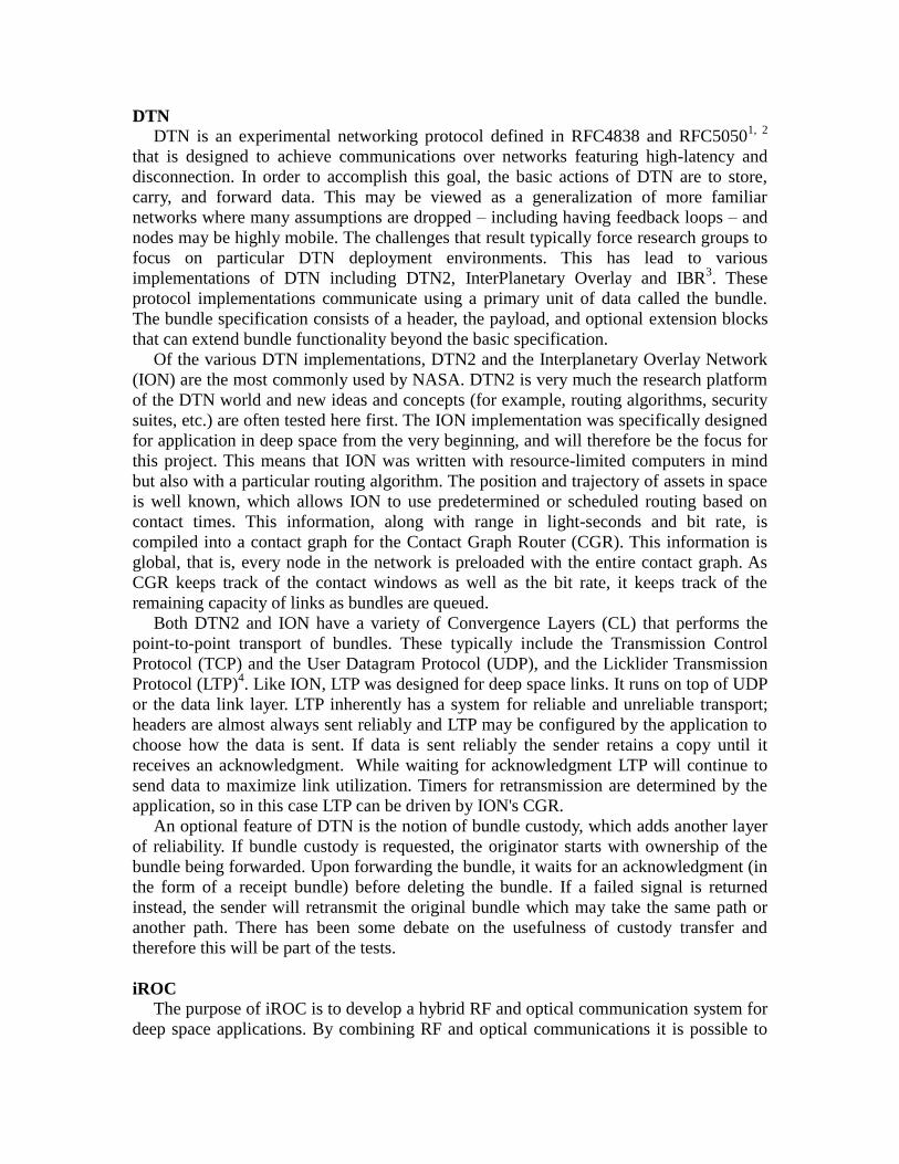
The hybrid RF/optical aperture, referred to as a teletenna, accomplishes two links
through the same aperture. It is a co-located co-bore-sighted RF antenna and optical
reflector. By power constraints, usually only one link is active at a given time. There are
scenarios for each link where one bests the other. Given a path to the receiver that is
obstruction-free, the optical link enables the highest bit rates. However, cloud obscuration
and other phenomena may prohibit optical communications, at which point RF becomes
the only choice. Furthermore, if the Sun is behind the iROC terminal, RF will have to
take precedence. Figure 1 shows the optical teletenna mentioned in this paper. The inner
disk is the optical surface and the entire dish is an RF reflector. Figure 2 shows the Free
Space Optical (FSO) links on the optics table. There are also instances where it is useful
to use both links simultaneously. As the aperture is co-located and co-bore-sighted,
acquisition on an optical ground station implies that nearby RF ground stations would be
able to retrieve data as well. This is aided by weather, pass, and connectivity information
being known in the geographical region. Usefulness is found in higher throughput but
also in running multicast over RF.
Figure 2. Free Space Optical Links
II. DTN and iROC
It is worth investigating if DTN should be applied to an optical terminal in space,
whether deep-space or near-earth. While iROC is used to motivate the use and
development of DTN, it should be noted that many challenges generalize to other optical
channels. From the network viewpoint, iROC may be considered three links – two
senders, one receiver. The receiver link is RF only and independent of the teletenna. This

introduces several complications, one of which is asymmetry. ION does not expect
symmetric up and down links, indeed ION inputs (the inducts) and outputs (outducts) are
declared separately; even unidirectional links are allowed.
Routing
As orbiting bodies move there will be many periods where there is no direct line of
sight for communications. This form of scheduled disconnection is precisely what CGR
is for. However, there are a few caveats. For an optical terminal between the Moon and
the Earth, the latency will be measured in seconds. This is short enough to allow for a
feedback loop, which allows for reactive switching between the optical link and the RF
link. However, this is not trivial regarding nuances of the protocol as the link capacities
are very different and some sense of bundle fragmentation may be required. From deep
space, the one-way light time will be in minutes and beyond, which prohibits reactive
switching, and instead proactive switching would need to be used. This information may
be determined by, for example, weather forecasts.
Another routing concern is that iROC may have line of sight to a variety of receivers,
but physically it can only choose one. This selection can be built into CGR, but this does
not scale. iROC is a special interface which is assembled into a network by DTN.
Choosing a link will necessarily cut off the others, and switching between links
introduces a period of no connectivity as the mechanical system must acquire and then
point to a new target. This issue is automatically taken care of by the store and carry
mechanisms of DTN.
Consider the case of two iROC terminals transmitting data to a satellite in
geostationary orbit to mitigate atmospheric effects. Suppose this relay node has two
optical receivers and both terminals are in view simultaneously. Then the relay will suffer
from asymmetry – two very high bit rate links will be sending bundles to the relay, which
will then have to buffer them while it transmits to the ground. If the relay only receives
from one terminal at a time, then the other terminal must buffer its own data. This notion
of local versus distributed storage is tricky due to the amount of coordination between
missions (current and planned) as well as the non-volatile storage capacities of the
various nodes.
Security
DTN does not currently support policy management or enforcement. As illustrated
above, this will have to be addressed. A DTN agent’s policies regarding resource control
and distribution will need to be able to guarantee enough storage for missions as they
come and go. This is a local policy. A DTN agent may also need to maintain some
awareness of network congestion (how full buffers are in other DTN agents located
multiple hops down the route path). This is global congestion sensing. While ION does
not perform autonomous neighbor discovery, new nodes can be added while the network
is operating. This is accomplished by running the associated administration utilities; the
information added would include names, inducts, outducts, and the CGR data. As the
network changes with time certain nodes might need to enforce strict control over who
talks to whom with a DTN equivalent of a firewall. This bundle protocol firewall
extension to DTN is in its very early stages of development at NASA.
Security protects the networks against several types of problems. One is the
unintentional, the other intentional. As of this writing, there are three orbiters around
Mars – two are NASA's, one is ESA's. None of these satellites are networked with each
other. Depending on where NASA's satellites are placed in Mars orbit it may be optimal
for them to share data. A motivational situation is when one satellite is about to be
obscured by Mars and still has some data left to transmit before Mars and its satellites
pass behind the sun. To ensure that resources are managed properly, in the very least a
technology like a Bundle Protocol (BP) firewall must be introduced. When multiple
customers on the ground start sharing assets, deeper separation must be possible as well.
And clearly, there must be security options for international communications; this is as
true for inter-satellite networking as it is for sharing ground stations.
There are several security extensions for DTN already. The primary suite is the Bundle
Security Protocol (BSP)5. The BSP includes the Bundle Authentication Block (BAB), the
Payload Integrity Block (PIB), and the Payload Confidentiality Block (PCB). These are
extension blocks that may be added to a bundle to provide a basic level of security to the
bundles transmitted across the DTN. The BAB provides hop-by-hop authentication
between two security-aware bundle agents. When crossing organizational boundaries this
may be necessary as a form of customs control in order to prevent the injection of rogue
bundles by an unauthorized third party. However, the BAB introduces two concerns in its
current incarnation. One is that authentication between neighbors is accomplished by
shared symmetric keys that must be pre-loaded manually due to lack of a key
management infrastructure in the specifications. Key management in a disconnected
network is a largely unexplored topic of research – indeed, a key revocation message
might not propagate for a very long time. Another issue is that the BAB is really
commonly composed of two extension blocks – one before the payload (and all other
extension blocks) containing the BAB header and one after the payload (and all other
extension blocks) containing the security result length and the security result (the digest
of the bundle). This means that the DTN recipient must receive the entire bundle before
declaring it authentic or not. If the bundle is very large this effectively creates a denial of
service attack as onboard resources could potentially be exhausted before the incoming
bundle could even be authenticated. This must be addressed even before considering
bundle sizes that are on the order of or larger than the amount of RAM in a given DTN
node. The PIB is an end-to-end cryptographic authentication block that allows the
destination and intermediate nodes with the proper keys, to verify the integrity of the
bundle. Like BAB, the PIB could potentially be used for hop-by-hop authentication if the
intermediate node has the appropriate key, but the original design intent was to provide
the final destination node a way to verify whether or not the bundle was altered in transit.
A somewhat hidden issue is that of bundle fragmentation. Due to short contact times it
may be that only a portion of a bundle can be transmitted during a contact period, leaving
transmission of the remainder of the bundle for the next schedule contact. If this action is
scheduled in advance it is called proactive fragmentation – fragmenting data before it is
sent to maximize link utilization. If two neighbors are physically close enough to have a
feedback loop, then certain transmission errors (such as those caused by rain fade) may
result in partial bundles being sent from one location to another. This on the fly process is
referred to as reactive fragmentation. In either case, the ability to fragment bundles is
useful. Current implementations of the ION DTN protocol specification do not appear to
support either reactive or proactive fragmentation when utilizing the Bundle Security
Protocol. A fragmented bundle will be treated as a corrupted bundle and rejected.
Scientific data might not always need encryption, but satellite commands might.
Encryption is possible below the DTN layer, at the DTN layer, and above at the
application layer. Within DTN, the BSP supports the Payload Confidentiality Block
(PCB) and the Extension Security Block (ESB), both of which offer end-to-end
encryption. Examples of lower layer encryption include the Soldier Radio Waveform,
which already has NSA approved security6. At the application layer one may consider the
case of e-mail where messages may be signed and/or encrypted on a case-by-case basis.
By its nature, encryption can be difficult to accommodate performance-wise in satellite
systems. DTN implementations involving encryption will need to be carefully considered
with regards to its impact on overall communication system performance.
Just as RF beams diverge (spread out over a distance), so do laser beams. The
difference is that from geostationary orbit, a laser's spot size diameter will be on the order
of kilometers whereas RF will paint the facing side of the earth. This offers a physical
security benefit to optical communications, as it is has limited coverage. Thus optical
space terminals might have a particular utility within military networks and particular pay
for service where dissemination, probably in the form of a multicast or broadcast, would
occur from an optical ground station.
Hardware Implementation of DTN
ION's requirement to operate on resource-limited platforms lead to the use of Zero-
Copy Objects (ZCO). The basic premise is to shallow-copy as much information as
possible. This includes file transfers. Sending a file means allocating space for the bundle
header but only copying chunks of data from the file as they are being transmitted. The
chunk size depends on the frame size – for UDP the maximum is 64 KB. The ZCO
method minimizes RAM utilization but has certain limitations. Adoption of iROC into
space networks hinges on iROC transmitting successfully within the 1-5 Gb/s range.
Forcing the CPU's to move data from non-volatile storage to RAM to the iROC interface
at these rates would cause undue burden. Indeed, the protocol may preclude other duties
assigned to the same processor.
A potential solution being researched is the partial implementation of ION in FPGAs
to affect a form of direct memory access. Offloading the non-computational overhead to
hardware should significantly decrease ION's footprint without adding excessive
complexity to the rest of the system; the data transfer could reside in the same FPGA as
the encoder and modulator. To maintain flexibility and the ability to update the protocol,
most of ION would remain in the computer. This also defeats the difficulty of
implementing a file system in VHDL. If the modulator and encoder were put in an ASIC,
the data transfer portion of DTN should move with them. This is because the mechanisms
to move data should be static once established.
III. Tests
While some of the requirements for DTN to support iROC may be discerned by
critical thinking, others become apparent during testing. A successful test was performed
at JPL with ION running in a FSO network7. Our work builds upon this. The goal was to
determine the current state of DTN and to see where it needs to go from there.

Testbed
The testbed consists of six computers, five of which act as DTN nodes. The chosen
version of DTN was ION 3.0.1. To reflect the limitations of space computers, each DTN
node has a first generation Pentium 4 and 512 megabytes of RAM (which, admittedly, is
still significantly more powerful than the 133 MHz radiation-hardened PowerPC CPUs
the current generation of spacecraft utilize which are often underclocked to 33 MHz to
conserve power). All computers are running Ubuntu 11.10. The chosen scenario was for
an emulated Mars orbiter to talk directly to one of three Deep Space Network (DSN)
ground stations on the Earth. The DSN sites then connected to a common Mission
Operation Center (MOC). The sixth non-DTN node was a channel emulator that gives a
ten-minute latency (twenty minutes round trip) between Mars and any DSN site.
Optics
The Mars satellite is connected to the channel emulator, which is in turn connected to
three 10Base-T to 10Base-FL single-mode media converters. The choice to use 10 Mb/s
links was largely motivated by budget but turned out to not be a constraint. This will be
addressed.
As there are three DSN sites, there are a total of six converters – three on the Mars
side and one on each of the DSN sites. Each converter box has two ST fiber connections
that are coupled to lenses. Respective pairs of lenses were carefully aligned on an optics
table. The JPL test used a similar converter and featured intermittent connectivity. As it
has been shown, the underlying transmission protocol, LPT, can handle this. We
scheduled connections from Mars to the DSN sites as calculated using the Satellite
Toolkit (STK). Background noise was introduced simply by not covering the FSO links
and exposing those links to ambient light (leaving the lights on). This was of minimal
impact.
Satellite Toolkit
To create the mission contact times the software package STK was used. STK enables
users to construct realistic scenarios including space assets and Earth assets. It allows for
considerations like separation angles from the sun and maintains a database on assets
including their orbits and positions. The month of June, 2012, was chosen as window to
run the scenario as Mars was relatively close (ten minutes away). STK Azimuth,
Elevation, and Range (AER) reports were calculated for each of the Mars orbiter to DSN
links, and a representative sample was chosen to configure CGR. A GUI tool was written
to facilitate the parsing of the data and the conversion to an ION friendly format. Plans
are to make this tool publicy available for DTN researchers.
Computer Setup
For ease of configuration, the Internet Protocol and associated hardware interfaces
were used as the underlying network. There are two networks that need to be configured:
the DTN communication path and the backchannel for configuration of computers and
network synchronization. Refer to Figure 3 for the network diagram for details. The Mars
computer and the DSN sites are each given an address on their own subnet. The DSN

sites and the MOC are given addresses on a separate subnet. The Address Resolution
Protocol (ARP) was configured to be static on the Mars/DSN subnet as resolution across
the ten-minute latency caused by the channel emulator would fail. By inspection with
tcpdump, IPv6 was found to be very chatty and was therefore disabled on all computers.
Figure 3. Network Diagram
Bundles do not have a built in hop counter. Rather, bundles have an expiration time or
time-to-live (TTL) which is determined in seconds. This is done with absolute time.
Moreover, the CGR action is also based on accurate time. Thus, all nodes must be
synchronized. Clock synchronization within the bundle protocol has been identified as a
know issue8. It was encountered even in the lab environment. The problems included
bundles being sent prematurely or being received too late resulting in false expiration.
They also included CGR not recognizing that link was up and not sending bundles. To
counter this problem a back channel was added between all DTN nodes and the MOC
which was designated as an NTP server in order to simulate the more highly accurate
clocks installed on spacecraft. NTP kept the time synchronized between the nodes and
eliminated the time-related communications problems.
The publically available channel emulator creates a ten-minute delay9. It bridges the
interfaces and stores packets in RAM. The calculated maximum that it would need, based
on bundle expiration times and three 10 Mbps links, was on the order of 4 gigabytes.
DTN
DTN uses naming as opposed to addressing, which works in smaller networks and
networks where all interaction is up to a global schedule. ION uses the Interplanetary
Naming (IPN) scheme where names are numerical. DSN1 was designated 1, DSN2 was
2, DSN 3 was 3, Mars was 4, and the MOC was 5. ION uses LTP to communicate
between Mars and the DSN sites, and TCP is between the DSN sites and the MOC. The
TCP portion is very straightforward to setup and all tests, including sending gigabyte
bundles, worked well.
LTP was non-trivial to configure due to the need to anticipate how much overhead is
required. One complication is that several sessions may run concurrently. For each
session there had to be enough memory to hold a frame's worth of data, which is
dependent on the lower layer protocol. In this case, LTP was run on top of UDP and
therefore all bundles were broken down into a maximum of 64 KB chunks. This memory
all resides in the Simple Data Recorder (SDR), which is ION's memory manager. When

starting ION the user declares how much heap ION will need. All of the data structures
are allocated within this space by ION. Furthermore, the size of the heap is static. The
intention is that when launching a satellite all software requirements are known ahead of
time so each process is given exactly what it needs. The implication is that the more
memory allocated to LTP, the less memory is available for other ION functions such as
adding bundles to an outgoing queue.
Test Setup
The original intention was to send as much data from Mars to the MOC as possible
with and without custody transfer. Due to limitations in the capacity of the Mars to Earth
communications path, it has been shown that current sensors on Mars orbiters run at 5%
capacity. For an optical terminal to really demonstrate its prowess it needs to remove the
bottleneck from communications as much as possible. This is also a dictum for DTN as
the protocol is responsible for the integration of the optical terminal into the network. A
variety of tests were planned, but with each passing run more restrictions were found. It
was found that on the TCP links all transfers were successful. The LTP links, on the other
hand, become unreliable when sending bundles over 64 megabytes. It was determined
that this was not a channel emulator issue by running tests outside of ION between the
nodes, but it may have been a problem within the FSO links. Five test files were made
from /dev/urandom of 10 KB, 100 KB, 1 MB, 10 MB and 64 MB sizes.
The links from the DSN sites to the MOC were always on and always had a one-way-
light-time of 0 seconds. The links between Mars and the DSN sites always had a distance
of ten minutes each way. The CGR configuration file consists of range and contact
statements. The range is the distance in seconds between assets and is commutative (the
distance from A to B is the distance from B to A). The contact statements are per
direction and include bit rate allowing explicitly asymmetric links. The test was run over
a three and a half day period, and the range statements are show in their entirety:
Code Excerpt 1: ION Range Statements
The “a” means add – we are adding to the table. In the first line, the +0 +3413 is a
time period for which this range is valid. The preceding plus sign signifies that this starts
so many seconds after ION started. The “4 1” refers to two nodes. Mars is node 4, and
DSN 1 is node 1. The 600 is the ten minute delay. So altogether, this means that
immediately after ION started until 3413 seconds elapsed, nodes 4 and 1 were able to
a range +0 +3413 4 1 600
a range +0 +8731 4 2 600
a range +9586 +23315 4 2 600
a range +43690 +89623 4 1 600
a range +70918 +95162 4 3 600
a range +95803 +109692 4 2 600
a range +129976 +175834 4 1 600
a range +157198 +181592 4 3 600
a range +182020 +196071 4 2 600
a range +216262 +262046 4 1 600
a range +243479 +268021 4 3 600
a range +268237 +282451 4 2 600
communicate and were 600 seconds separated. As we were limited to 64 megabyte
bundles, we allowed links to overlap. Only two ground stations allow for overlap which
corresponds to the case where optical acquisition also enables RF communication to
nearby stations. Both links were run allowed to run at line rate. The restriction to one link
at a time simply means cutting the range and contact times such that there is no overlap.
It is too early to tell how much time is lost due to the mechanics of acquisition and
therefore this was left out for this preliminary paper.
Blackholing a route means that incoming traffic is silently discarded (or "dropped"),
without informing the source that the data did not reach its intended recipient. During
periods of non-connectivity, routes were blackholed to ensure that there was no slop in
the system. In retrospect, by inspection with tcpdump (a free open source packet sniffer
utility), we determined CGR was operating correctly and blackholing was not needed.
Tests
After preliminary tests were conducted to establish the limits, two tests were run. Each
test attempted to get as many bundles from Mars to the MOC as possible. The basic idea
was to send a 64 megabyte file, then a random smaller file, wait three seconds, and
repeat. The three-second wait corresponded to the supposed throughput of the links. The
first test was run without custody transfer and the second with hop-by-hop custody
transfer. Each successfully received bundle was logged and its checksum computed.
IV. Observations
The first test, without custody transfer, was actually run twice. The heap is an area of
pre-reserved computer main storage (memory) that a program can use to store data in
some variable amount that won't be known until the program is running. The needed heap
was calculated incorrectly and insufficiently. This was because it turned out that LTP in
ION ran much slower than line rate. This resulted in the queue of outgoing bundles
growing too large causing ION to crash. The second test was run with custody transfer
and a larger heap. The heap was increased as large as it would go without crashing ION.
As the OS was willing to grant more memory to other applications it was unclear how the
upper limit was set. This still resulted in the SDR being too full to accept new incoming
bundles. The first test was rerun with the new heap value.
The original heap value was set at 27 megabytes. The highest stable point achieved
was 32 megabytes. The first showed low heap warnings during a contact period 5 hours
and 31 minutes into the test. The second and third test both had heap warnings 8 hours
and 45 minutes into the test. This corresponds to two and one-quarter hours into a period
with no contacts whatsoever. Given the rate at which bundles were being sourced, this
means that we ran out of heap after about 2700 bundles were in the queue.
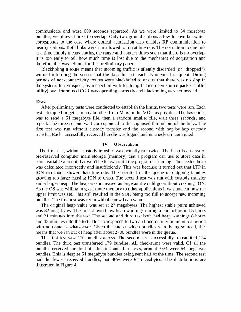
The first test saw 120 bundles across. The second test successfully transmitted 114
bundles. The third test transferred 179 bundles. All checksums were valid. Of all the
bundles received for the both the first and third tests, around 35% were 64 megabyte
bundles. This is despite 64 megabyte bundles being sent half of the time. The second test
had the fewest received bundles, but 46% were 64 megabytes. The distributions are
illustrated in Figure 4.
Figure 4. Bundle Reception Summary
V. Future Work and Conclusions
Given the complexity of establishing routes in space ION is automatically a good
choice for an optical communications terminal in space. There are a few areas where ION
needs improvement – particularly in its LTP implementation. Running out of heap with
2700 bundles in the queue is fair, but the reason that there were so many bundles was
because of the limitations on bundle size. Taking it a step further, during periods with no
connectivity some form of bundle aggregation – with aggregation indexing stored in a
file – would save memory.
While custody transfer resulted in a more even distribution of transfers it did hold
back the performance. With the same heap, 65 more bundles made it without custody
transfer. It is therefore necessary to run some new tests with a variety of file sizes. As
discussed, sending fewer but larger bundles would save heap size for ION. It may be that
custody transfer makes more sense for these larger bundles because then the heap would
not be in jeopardy. At the same time, these large bundles would remain resident on the
non-volatile storage and may overrun other resources. Thus until the issue is ironed out it
is recommended that custody transfer is not used except on a privileged few bundles.
CGR will need to be extended to allow establishment of one link to preclude all others
– at least when they share a common outduct. This may eventually need to include
support for multiple optical links, each of which having independent gimbals, so that two
optical links do not acquire the same receiver. The current reality does not require so
much flexibility, however.
More research will need to be conducted regarding security. Several parameters,
including bundle size and fragmentation, need to be exercised to determine impacts on
performance. It will need to be determined at what layer encryption takes place, if at all.
Also of note, of the thousands of bundles that were sourced, the most received
successfully during any of the tests by the destination was 170.
Future tests at the Glenn Research Center include a FSO link over rooftops between
buildings. This testbed would include modulation and encoding that are not Ethernet, and
LTP would operate on top. They would also include the partial FPGA implementation of
ION, which is under development.

It is clear that despite a few setbacks with the current ION implementation, DTN
offers great utility when coupled with optical communication between space and ground.
Many challenges presented by networking in the unforgiving space environment are well-
met by DTN, and ION’s CGR router makes the most sense given the intended
application.
Acknowledgments
The authors would like to thank the NASA SCaN program, and in particular Mr. John
Rush, for supporting this research.
References 1 Kevin Fall, Keith L. Scott, Scott C. Burleigh, Leigh Torgerson, Adrian J. Hooke, Howard S. Weiss, Robert C.
Durst, and Vint Cerf, “Delay-Tolerant Networking Architecture”, RFC4838, 2007, http://tools.ietf.org/html/rfc4838 2 Keith Scott, Scott Burleigh, “Bundle Protocol Specification”, RFC5050, 2007, http://tools.ietf.org/html/rfc5050 3 Delay Tolerant Networking Research Group, Retrieved July 10th, 2012, http://www.dtnrg.org 4 Ramadas, M; Burleigh, S; Farrell, S; “Licklider Transmission Protocol – Specification,” RFC5326, September
2008 5 Susan Symington, Stephen Farrell, Howard Weiss, and Peter Lovell, “Bundle Security Protocol Specification”,
2011, http://tools.ietf.org/html/draft-irtf-dtnrg-bundle-security-19 6 Ken Peterman, “Soldier Radio Waveform ushers in new era in tactical communications”, November 10, 2009,
http://defensesystems.com/articles/2009/11/18/industry-perspective.aspx 7 Schoolcraft, J.; Wilson, K., “Experimental characterization of space optical communications with disruption-
tolerant network protocols,” Space Optical Systems and Applications (ICSOS), 2011 International Conference on, 11-
13 May 2011. 8 Torgerson, J. Leigh; Richard Borgen, Richard; McKelvey, James; Segui, John; Tsao, Phil, “DARPA DTN Phase 3
Core Engineering Support”, April 30, 2010 9 Joseph Ishac, “Channel Emulator Resources”, June 3, 2009, http://channel-emulator.grc.nasa.gov


![Delay/Disruption-Tolerant Networking: Flight Test Results ...Tolerant Networking (DTN) [2,3] can maximize the efficient use of links to and among spacecraft. As part of NASA’s efforts](https://static.fdocuments.net/doc/165x107/5ff2e67d4488aa36cb7046a6/delaydisruption-tolerant-networking-flight-test-results-tolerant-networking.jpg)