OMX 102UNI - Adel Instrumentation...OMX 102UNI is a multifunctional instrument with 8 possible input...
92
OMX 102UNI PROGRAMMABLE UNIVERSAL TRANSMITTER DC VOLTMETER/AMMETER PROCESS MONITOR OHMMETER THERMOMETER FOR PT/NI/CU THERMOMETER FOR THERMOCOUPLES DISPLAYS FOR LINEAR POTENTIOMETERS GUARANTEE Y E A R S TECHDOK - OMX 102UNI - 2014 - 1v0 - en
Transcript of OMX 102UNI - Adel Instrumentation...OMX 102UNI is a multifunctional instrument with 8 possible input...

OMX 102UNIPROGRAMMABLE
UNIVERSAL TRANSMITTER
DC VOLTMETER/AMMETERPROCESS MONITOR
OHMMETERTHERMOMETER FOR PT/NI/CU
THERMOMETER FOR THERMOCOUPLESDISPLAYS FOR LINEAR POTENTIOMETERS
GUARANTEE
Y E A R S
TECHDOK - OMX 102UNI - 2014 - 1v0 - en

2 | INSTRUCTIONS FOR USE OMX 102UNI
SAFETY INSTRUCTIONSPlease, read the enclosed safety instructions carefully and observe them!These instruments should be safeguarded by isolated or common fuses (breakers)! For safety information the EN 61 010-1 + A2 standard must be observed. This instrument is not explosion-safe!
TECHNICAL DATAMeasuring instruments of the OMX 102 series conform to the European regulation 89/336/EWG.
The instruments are up to the following European standards:EN 61010-1 Electrical safetyEN 61326-1 Electronic measuring, control and laboratory devices – Requirements for EMC “Industrial use”
Seismic capacity:IEC 980: 1993, čl. 6
The instruments are applicable for unlimited use in agricultural and industrial areas.
CONNECTIONSupply of energy from the main line has to be isolated from the measuring leads.
ORBIT MERRET, spol. s r.o.Vodnanska 675/30 198 00 Prague 9Czech Republic
Tel: +420 - 281 040 200Fax: +420 - 281 040 299e-mail: [email protected]

INSTRUCTIONS FOR USE OMX 102UNI | 3
1.CONTENTS
1. CONTENTS . . . . . . . . . . . . . . . . . . . . . . . . . . . . . . . . 3
2. INSTRUMENT DESCRIPTION . . . . . . . . . . . . . . . . . . . 4
3. INSTRUMENT CONNECTION . . . . . . . . . . . . . . . . . . . . 6
Measuring ranges . . . . . . . . . . . . . . . . . . . . . . . . . . . . . 6
Instrument connection . . . . . . . . . . . . . . . . . . . . . . . . . 7
Recommended connection of sensors . . . . . . . . . . . 8
4. INSTRUMENT SETTING . . . . . . . . . . . . . . . . . . . . . . 10
Symbols used in the instructions . . . . . . . . . . . . . . . 12
Setting the DP and the (-) sign . . . . . . . . . . . . . . . . . 12
Control keys function . . . . . . . . . . . . . . . . . . . . . . . . . 13
Setting/permitting items into “USER” menu . . . . . . . 13
5. SETTING “LIGHT” MENU . . . . . . . . . . . . . . . . . . . . . .14
5.0 Description “LIGHT” menu . . . . . . . . . . . . . . . . . . . 15
Setting input - Type “DC” . . . . . . . . . . . . . . . . . . . . . . 18
Setting input - Type “102DC” . . . . . . . . . . . . . . . . . . .20
Setting input - Type “PM” . . . . . . . . . . . . . . . . . . . . . .22
Setting input - Type “OHM” . . . . . . . . . . . . . . . . . . . . . 24
Setting input - Type “RTD - Pt” . . . . . . . . . . . . . . . . . .26
Setting input - Type “RTD - Cu” . . . . . . . . . . . . . . . . .28
Setting input - Type “RTD - Ni” . . . . . . . . . . . . . . . . . .30
Setting input - Type “T/C“ . . . . . . . . . . . . . . . . . . . . . .32
Setting input - Type “DU“ . . . . . . . . . . . . . . . . . . . . . . 34
Setting Limits . . . . . . . . . . . . . . . . . . . . . . . . . . . . . . . .36
Setting analog output . . . . . . . . . . . . . . . . . . . . . . . . . 37
Selection of programming menu „LIGHT“/„PROFI“ . .38
Restoration of manufacture setting . . . . . . . . . . . . .38
Calibration - input range (DU) . . . . . . . . . . . . . . . . . . .39
Selection of instrument menu language version . . 40
Setting new access password . . . . . . . . . . . . . . . . . 40
Instrument identification . . . . . . . . . . . . . . . . . . . . . . . 41
6. SETTING “PROFI” MENU . . . . . . . . . . . . . . . . . . . . . 42
6.0 Description of “PROFI” menu . . . . . . . . . . . . . . . . . 42
6.1 “PROFI” menu - INPUT
6.1.1 Resetting internal values . . . . . . . . . . . . . . . . . 44
6.1.2 Setting measuring type, range, mode, rate. . 45
6.1.3 Setting the Real Time . . . . . . . . . . . . . . . . . . .53
6.1.4 External input function selection . . . . . . . . . . 54
6.2 “PROFI” menu - CHANNEL
6.2.1 Setting measuring parameters (projection, filters, decimal point, description). . . . . . . . . . . . . . . .56
6.2.2 Setting mathematic functions . . . . . . . . . . . .60
6.2.3 Selection of evaluation of min/max. value . .63
6.3 “PROFI” menu - OUTPUT
6.3.1 Setting of excitation level . . . . . . . . . . . . . . . . 64
6.3.2 Setting data logging . . . . . . . . . . . . . . . . . . . . . 64
6.3.3 Setting Limits . . . . . . . . . . . . . . . . . . . . . . . . . .66
6.3.4 Setting data output . . . . . . . . . . . . . . . . . . . . . 70
6.3.5 Setting analog output . . . . . . . . . . . . . . . . . . . 72
6.3.6 Setting of display backlight . . . . . . . . . . . . . . . 74
6.4 “PROFI” menu - SERVIS
6.4.1 Selection of programming menu „LIGHT“/„PROFI““ . . . . . . . . . . . . . . . . . . . . . . . 76
6.4.2 Restoration of manufacture setting . . . . . . . . 77
6.4.3 Calibration - input range (DU) . . . . . . . . . . . . . 78
6.4.4 Selection of instrument menu language version . . . . . . . . . . . . . . . . . . . . . . . 78
6.4.5 Setting new access password . . . . . . . . . . . 78
6.4.6 Instrument identification . . . . . . . . . . . . . . . . . 79
7. SETTING ITEMS INTO “USER” MENU . . . . . . . . . . . . 80
8. METHOD OF MEASURING OF THE COLD JUNCTION . 82
9. ERROR STATEMENTS . . . . . . . . . . . . . . . . . . . . . . . . 83
10. DATA PROTOCOL . . . . . . . . . . . . . . . . . . . . . . . . . . . 84
11. TABLE OF SYMBOLS . . . . . . . . . . . . . . . . . . . . . . . . 86
12. TECHNICAL DATA . . . . . . . . . . . . . . . . . . . . . . . . . . 88
13. INSTRUMENT DIMENSIONS AND INSTALATION . . . . 90
14. CERTIFICATE OF GUARANTEE . . . . . . . . . . . . . . . . . .91

4 | INSTRUCTIONS FOR USE OMX 102UNI
2. INSTRUMENT DESCRIPTION
2.1 DESCRIPTION
The OMX 102 model range are DIN rail mountable programmable transmitters designed with the utmost versatility and user comfort in mind whilst keeping the cost at a favourable level. The OMX 102 various executions are UNI, DC, PWR, UQC and T. As a standard the instrument is fitted with a backlit LCD display which projects measured values and configuration settings.OMX 102UNI is a multifunctional instrument with 8 possible input configurations easily adjustable in the instrument’s menu.The instrument is based on an 32-bit microcontroller, 24-bit A/D and 16-bit D/A converters, which ensures good accuracy, stability and easy operation of the instrument.
TYPES AND RANGES
UNI up to 2 individual inputs DC: ±30/±60/1000 mV; ±20/±40/±80 V; ±90/±180 mA PM: ±5/±20 mA/4…20 mA; ±2/±5/±10 V OHM: 0…100/300 Ω/0…1,5/3/24/30 kΩ RTD-Pt: Pt 50/100/500/1000 RTD-Cu: Cu 50/100 RTD-Ni: Ni 1 000/10 000 T/C: J/K/T/E/B/S/R/N/L DU: Linear potentiometer (min. 500 Ω)
DC ±1/±5 A; ±25/±50/±100/±200/±400 V
PROGRAMMABLE PROJECTION
Selection: of type of input and measuring rangeMeasuring range: adjustable Setting: manual, optional projection on the display may be set in the menu for both limit values of the input signal, e.g. input 0…20 mA > 0…150Projection: -99M…999M
ANALOG OUTPUTSType: isolated, programmable with resolution of max. 16 bit, rate < 1 msQuantity: up to 2Range: 0…2/5/10 V, ±10 V, 0…5 mA, 0/4…20 mA, 0,2…2 200 Hz
COMPENSATION
of conduct: in the menu it is possible to perform compensation for 2-wire connectionof conduct in probe: internal connection (conduct resistance in measuring head)of CJC (T/C): manual or automatic, in the menu it is possible to perform selection of the type of thermocouple and compensation of cold junctions, which is adjustable or automatic(temperature at the brackets)
LINEARIZATION
Linearization:* by linear interpolation in 50 points (solely via OM Link)
DIGITAL FILTERS
Floating average: from 2…30 measurementsExponen. average: from 2…100 measurementsArithmetic average: from 2…100 measurementsRounding: setting the projection step for display
* only for types DC, PM, DU

INSTRUCTIONS FOR USE OMX 102UNI | 5
2.INSTRUMENT DESCRIPTION
MATHEMATIC FUCTIONS
Min/max. value: registration of min./max. value reached during measurementTare: designed to reset display upon non-zero input signalFixed Tare: pre-set tare, fixedPeak value: the display shows only max. or min. valueMat. operations: polynome, 1/x, logarithm, exponential, power, root, sin x and mathematic operatin between input - total and divide
EXTERNAL CONTROL
Lock : control keys blockingHold : display/instrument blockingTare : tare activation/resetting tare to zeroResetting MM : resetting min/max valueMemory: data storage into instrument memorySwap: switching (swapping) between active inputs/outputs (where available)
2.2 OPERATION
The instrument is set and controlled by two control keys located on the front panel. All programmable settings of the instrument are performed in three adjusting modes:
LIGHT Simple programming menu - contains solely items necessary for instrument setting and is protected by optional number code
PROFI Complete programming menu - contains complete instrument menu and is protected by optional number code
USER User programming menu - may contain arbitrary items selected from the programming menu (LIGHT/PROFI), which determine the right (see or change) - acces without password
All programmable parameters are stored in the EEPROM memory (they hold even after the instrument is switched off).Complete instrument operation and setting may be performed via OM Link communication interface, which is a standard equipment of all instruments.
The operation program is freely accessible (www.orbit.merret.eu) and the only requirement is the purchase of OML cable to connect the instrument to PC. It is manufactured in version RS 232 and USB and is compatible with all ORBIT MERRET instruments. Another option for connection is with the aid of data output RS 232, RS 485, LAN and USB (without the need of the OML cable). The program OM LINK in „Basic“ version will enable you to connect one instrument with the option of visualization and archiving in PC. The OM Link „Standard“ version has no limitation of the number of instruments connected.
2.3 OPTIONS
Excitation is suitable for supplying power to sensors and transmitters. It has a galvanic separation.Comparators are assigned to monitor two limit values with relay output. The user may select limits regime: LIMIT/DOSING/FROM-TO. The limits have adjustable hysteresis within the full range of the display as well as selectable delay. Reaching the preset limits is signalled by LED and simultaneously by the switch-on of the relevant relay.Data outputs jare for their rate and accuracy suitable for transmission of the measured data for further projection or directly into the control systems. We offer an isolated RS232 and RS485 with the ASCII/Mesbus/MODBUS/PROFIBUS protocol, CAN and LAN.Measured data record is an internal time control of data collection. It is suitable where it is necessary to register measured values. Two modes may be used. FAST is designed for fast storage (40 records/s) of all measured values up to 8 000 records. Second mode is RTC, where data record is governed by Real Time with data storage in a selected time segment and cycle. Up to 250 000 values may be stored in the instrument memory. Data transmis sion into PC via serial interface USB, RS 232/485 and OM Link.

6 | INSTRUCTIONS FOR USE OMX 102UNI
3. INSTRUMENT CONECTION
The instrument supply leads should not be in proximity of the incoming low-potential signals.Contactors, motors with larger input power should not be in proximity of the instrument.The leads into the instrument input (measured quantity) should be in sufficient distance from all power leads and appliances. Provided this cannot be secured it is necessary to use shielded leads with connection to ground (bracket E). The instruments are tested in compliance with standards for use in industrial area, yet we recommend to abide by the above mentioned principles.
MEASURING RANGES
TYPE INPUT 1 INPUT 2 INPUT 3 INPUT 4 INPUT 5
DC ±20/±40/±80 V ±30/±60/±1000 mV ±90/±180 mA
PM ±2/±5/±10 V ±5/20/4…20 mA
T/C J/K/T/E/B/S/R/N/L
OHM 0…100/300 Ω/0…1,5/3/24/30 kΩ
RTD-Pt Pt 50/100/500/1 000
RTD-Cu Cu 50/100
RTD-Ni Ni 1 000/10 000
DU Linear potentiometer (min. 500 Ω)
OMX 102DC
TYPE INPUT 1 INPUT 2 INPUT 3 INPUT 4 INPUT 5
DC±25/±50/±100 V±200/±400 VChannel 1
0…1/5 AChannel 2

INSTRUCTIONS FOR USE OMX 102UNI | 7
3.INSTRUMENT CONECTION
NÁVOD K OBSLUZE OM 402UNI | 7
Ground wire must be connected to terminal „E“ at all times!
!
+ -
L1
L2
7 8 9 10
TxD
Rx/
Tx-
RxD
Rx/T
x+
232
485
S-S-
S+
E-
ES-E-
E+
ES+ES+
1 2 3
INP
UT
3
GN
D
-+
-+DU
OHM, RTD, Ni, Cu
T/C
16 17 18 201911 12 13 1514
AO
Volta
ge
++ + - +
GN
D
AO
Su
pply O
C
AO
Cu
rren
t
AO
Frequ
en
cy
AO
Volta
ge
++ + - +
GN
D
AO
Su
pply O
C
AO
Cu
rren
t
AO
Frequ
en
cy
AO
1
AO
2
PO
WER
+ - EL N
GN
DG
ND
+-
INP
UT 5
Chan
nel
2
F G H J KI
+ + + +
GN
D
INP
UT 1
INP
UT 2
INP
UT 3
INP
UT 4
+-
INP
UT 5
Chan
nel
1
+ + + +
GN
D
INP
UT 1
INP
UT 2
INP
UT 3
INP
UT 4
L M N P QO
EX
T. 2
EX
T. 1
Exc
itat
ion
R S T
ETH
ER
NE
T
USB
A B C D E
USB and OM Link are galvanic connected with input!
When iput wires are connected, a galvanic isolated USB cable MUST be used.
RISK OF DAMAGING YOUR COMPUTER
! USB
When using RTD or OHM inputs in 2-wire or 3-wire connection, it is essential connect unused inputs on the terminal board (M+N/O+P or O+P). The same applies to Channel 2.
!
Supply to open collector (OC) for frequency output is max. 40 V
(internal resistor 5k6)
!

8 | INSTRUCTIONS FOR USE OMX 102UNI
3. INSTRUMENT CONECTION
Example connection of a 2-wire sensor with current signal output powered by instrument’s excitation
Example connection of a 3-wire sensor with current signal output powered by instrument’s excitation
INPUT 5Excitation
(+)(-)
Sensor (-)Sensor (+)
1 2 3
16 17 18 2019
AO
Volta
ge
++ + - +
GN
D
AO
Su
pply O
C
AO
Cu
rren
t
AO
Frequ
en
cy
AO
1
SU
PP
LY+ - EL N
USB
+-
Chan
nel
1
+ + + +L M N P QO
+A B C D E
-
INPUT 5ExcitationOutput (+)Supply (+)
1 2 3
16 17 18 2019
AO
Volta
ge
++ + - +
GN
D
AO
Su
pply O
C
AO
Cu
rren
t
AO
Frequ
ncy
AO
1
SU
PP
LY
+ - EL N
USB
+-
Chan
nel
1
+ + + +L M N P QO
+A B C D E
-
Supply (+)Output (+)GND (-)

INSTRUCTIONS FOR USE OMX 102UNI | 9
INSTRUMENT CONECTION 3.
Example connection of 3-wire sensor with voltage signal output powered by instrument’s excitation
INPUT 1ExcitationOutput (+)Supply (+)
1 2 3
16 17 18 2019
AO
Vola
tge
++ + - +
GN
D
AO
Su
pply O
C
AO
Cu
rren
t
AV
Frequ
en
cy
AO
1
SU
PP
LY
+ - EL N
USB
+-
Chan
nel
1
+ + + +L M N P QO
+A B C D E
-
Supply (+)Output (+)GND (-)

10 | INSTRUCTIONS FOR USE OMX 102UNI
4. INSTRUMENT SETTING
SETTINGPROFIFor expert usersComplete instrument menuAccess is password protectedPossibility to arrange items of the USER MENUTree menu structure
SETTING LIGHTFor trained usersOnly items necessary for instrument settingAccess is password protectedPossibility to arrange items of the USER MENULinear menu structure
SETTING USERFor user operationMenu items are set by the user (Profi/Light) as per requestAccess is not password protected Optional menu structure either tree (PROFI) or linear (LIGHT)

INSTRUCTIONS FOR USE OMX 102UNI | 11
INSTRUMENT SETTING 4.
4.1 SETTING
The instrument is set and controlled by two control keys located on the front panel. All programmable settings of the instrument are performed in three adjusting modes:
LIGHT Simple programming menu - contains solely items necessary for instrument setting and is protected by optional number code
PROFI Complete programming menu - contains complete instrument menu and is protected by optional number code
USER User programming menu - may contain arbitrary items selected from the programming menu (LIGHT/PROFI), which determine the right (see or change) - acces without password
All programmable parameters are stored in the EEPROM memory (they hold even after the instrument is switched off).
Complete instrument operation and setting may be performed via OM Link communication interface, which is a standard equip-ment of all instruments. The operation program is freely accessible (www.orbit.merret.eu) and the only requirement is the purchase of OML cable to con-nect the instrument to PC. It is manufactured in version RS 232 and USB and is compatible with all ORBIT MERRET instruments.Another option for connection is with the aid of data output RS 232 or RS 485 (without the need of the OML cable).

12 | INSTRUCTIONS FOR USE OMX 102UNI
4. INSTRUMENT SETTING
Setting and controlling the instrument is performed by means of two control keys located on the front panel. With the aid of these keys it is possble to browse through the operation menu and to select and set required values.
Symbols used in the instructions
DC PM DU OHM RTD T/C Indicates the setting for given type of instrument
DEF values preset from manufacture
42 symbol indicates a flashing light (symbol)
MIN inverted triangle indicates the item that can be placed in USER menu
CON. broken line indicates a dynamic item, i.e. it is displayed only in particular selection/version
after pressing the key the set value will not be stored
after pressing the key the set value will be stored
30 continues on page 30
Setting the decimal point and the minus sign
DECIMAL POINTIts selection in the setting mode is performed by control key with transition behind the highest decade, when thedata starts flashing. Positioning is performed by . For projection of value exceeding 999 the suffix may be set „m“ - 0,001, „k“ - 1000 or „M“ - 100 000
THE MINUS SIGNSetting the minus sign is performed by control key on the higher decade. When editing the item, figures changein numeric row 0,1…9,-,0,1
1 2
INPUT
OUTPUT
Signalling (green LED)
ON LED is litON LED is flashing - Error messageOFF LED is not lit
Output value
+ displaying 3-character,user selectable
measuring units
Input value
+ displaying 3-character,user selectablemeasuring units
Control buttons
Relay status (red LED)
ON the digit is litOFF the digit is not litOFF the digit is flashing
limits with restriction(hysteresis, delay)

INSTRUCTIONS FOR USE OMX 102UNI | 13
INSTRUMENT SETTING 6.
Control keys functions
Setting items into „USER“ menu
• in LIGHT or PROFI menu
• no items permitted in USER menu from manufacture
• on items marked by inverted triangle
NO item will not be displayed in USER menu
YES item will be displayed in USER menu with the option of setting
SHO. item will be solely displayed in USER menu
KEY MEASUREMENT MENU SETTING NUMBERS/SELECTION
value of tare (DC, PM)
measured resistance (RTD)
cold junction compensation (T/C)
swapping inputs
back to previous level move to higher decade
Tare/Reseting move to next item move up
+ confirm selection confirm setting/selection
+ < 2 s
access into LIGHT menu
+ > 2 s
direct access into PROFI menu
access into USER menu
USER
--- NO YES SHO. ---
return to item
legend is flashing - current setting is displayed
> 2s

14 | INSTRUCTIONS FOR USE OMX 102UNI
5. SETTING LIGHT
SETTING LIGHTFor trained usersOnly items necessary for instrument settingAccess is password protectedPossibility to arrange items of the USER MENULinear menu structure
INSTRUCTIONS FOR USE OMX 102UNI | 15
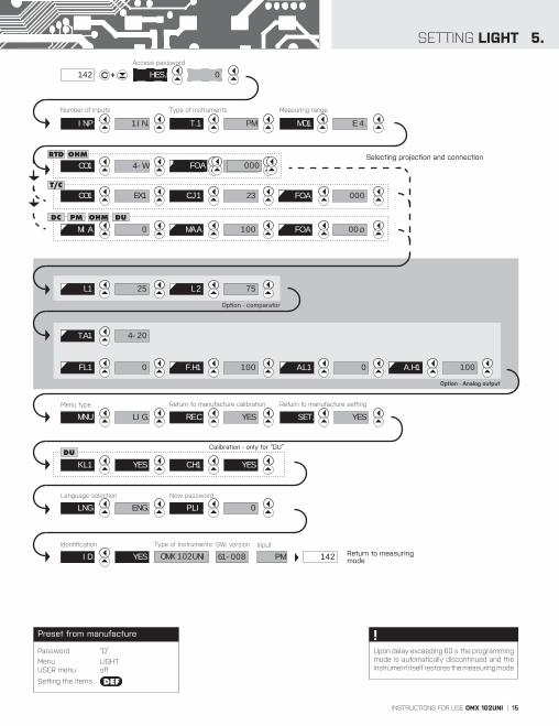
SETTING LIGHT 5.
Option - comparator
142 HES. 0+
Access password
4-WCO.1 00.oFOR.
OHMRTD
EX.1CO.1 23C.J.1 FO.A 000
Selecting projection and connection
T/C
0MI.A 100MA.A FO.A 00.o
PMDC DUOHM
Option - Analog output
T.A.1 4-20
F.L.1 F. H.1 1000
Calibration - only for “DU”
K.L.1 YES C.H.1 YES
DU
MNU LIG.
Menu type
L.1 25 L.2 75
A.L.1 A. H.1 1000
Return to manufacture calibration
RE.C. YES
Language selection
LNG. ENG.
Identifi cation
ID. YES OMX 102UNI
Type of instrumentsReturn to measuring mode14261-008 PM
SW: version Input
E 4.
Measuring range
MO.1
Type of instruments
PMT. 1
000FO.A
Number of inputs
1.IN.INP.
Return to manufacture setting
SET. YES
New password
P.LI. 0
Upon delay exceeding 60 s the programming mode is automatically discontinued and the instrument itself restores the measuring mode
!Password “0”
Menu LIGHT USER menu off
Setting the items DEF
Preset from manufacture

16 | INSTRUCTIONS FOR USE OMX 102UNI
5. SETTING LIGHT
142
PAS. 0Entering access password for access into the menu
PAS. Access into instrument menu
PAS = 0
- access into menu is unrestricted, after releasing keys you automaticaly move to first item of the menu
PAS > 0
- access into menu is protected ny number code
Set “PAS.” = 42 Example
0 1 2 02 12
42
22
32 INP.
INP. Selecting the number of active inputs
- this menu item is accessible only when the unit has 2 inputs
- DEF = „2.IN.“
INP.
Menu Description
1.IN. active input 1
2.IN. active inputs 1 and 2
INP.
Inputs “2.IN.“ Example
1.IN. 2.IN.
T. 12.IN.
+
INSTRUCTIONS FOR USE OMX 102UNI | 17
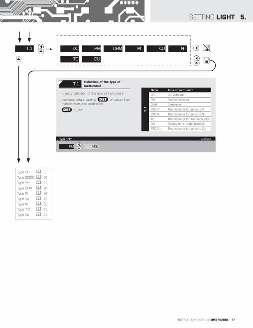
SETTING LIGHT 5.
T. 1 Selection of the type of instrument
- primary selection of the type of instrument
- performs default setting DEF of values from manufacture, incl. calibration
- DEF = „PM“ T. 1
Menu Type of instrument
DC DC voltmeter
PM Process monitor
OHM Ohmmeter
RTD-Pt Thermometer for sensors Pt
RTD-Ni Thermometer for sensors Ni
TC Thermometer for thermocouples
DU Display for lin. potentiometer
RTD-Cu Thermometer for sensors Cu
T. 1
Type “PM” Example
DC PM OHM Pt CU NI
TC
MO.1PM
DU
Type DC 18
Type 102DC 20
Type PM 22
Type OHM 24
Type Pt 26
Type Cu 28
Type Ni 30
Type T/C 32
Type Du 34

18 | INSTRUCTIONS FOR USE OMX 102UNI
SETTING LIGHT5.M
EAS
UR
ING
MO
DE
> D
C
MI.A Setting display projection for minimum value of input signal
- range of the setting: -99M…999M
- position of the DP does not affect display projection
- the DP is automatically shifted after the value is confirmed
DEF = 0
MO.1 Selection of the instrument measuring range
DEF = 60 mV
MO
.1
Menu Measuring range
30m ±30 mV
60m ±60 mV
u 1 ±1 V
u20 ±20 V
u40 ±40 V
u80 ±80 V
i0.1 ±90 mA
i0.2 ±180 mA
Projection for 0 mV > MI.A = 0 Example
0Setting for minimum input signalMI.A
MO.1
Range 1 V Example
60m u 1 MI.A
MA.A 0
30m 60m u 1 u80u20 u40
i0.1 i0.2

INSTRUCTIONS FOR USE OMX 102UNI | 19
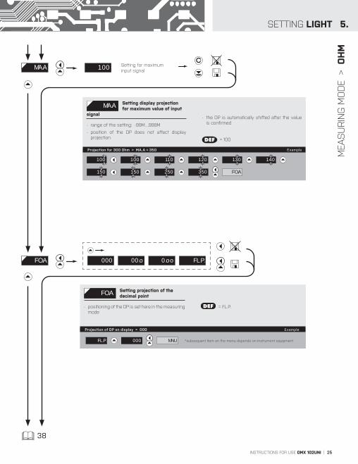
FO.A Setting projection of the decimal point
- positioning of the DP is set here in the measuring mode
DEF = FL.P.
MEA
SU
RIN
G M
OD
E >
D
C
5.SETTING LIGHT
100
MA.A Setting display projection for maximum value of input
signal
- range of the setting: -99M…999M
- position of the DP does not affect display projection
- the DP is automatically shifted after the value is confirmed
DEF = 100
Setting for maximum input signal
MA.A
Projection for 60 mV > MA.A = 500 Example
38
FO.A
100 100
500
400 300 200 100
Projection of DP on display > 000 Example
FO.A
MNU *subsequent item on the menu depends on instrument equipment
000 00.o 0.oo FL.P.
FL.P. 000

20 | INSTRUCTIONS FOR USE OMX 102UNI
SETTING PROFI6.M
EAS
UR
ING
MO
DE
> O
MX
10
2D
C
MI.A Setting display projection for minimum value of input signal
- range of the setting: -99M…999M
- position of the DP does not affect display projection
- the DP is automatically shifted after the value is confirmed
DEF = 0
MO.1 Selection of the instrument measuring range
DEF = 200 V
MO
.1
Menu Measuring range
25 ±25 V
50 ±50 V
100 ±100 V
200 ±200 V
400 ±400 V
1 A ±1 A
5 A ±5 A
Projection for 0 V > MI.A = 0 Example
0Setting for minimum input signalMI.A
MO.1
Range 400 V Example
200 400 MI.A
MA.A 0
25 50 100 200 400
1 A 5 A

INSTRUCTIONS FOR USE OMX 102UNI | 21
6.SETTING PROFI
FO.A Setting projection of the decimal point
- positioning of the DP is set here in the measuring mode
DEF = FL.P.
MEA
SU
RIN
G M
OD
E >
O
MX
10
2D
C
100
MAX.A Setting display projection for maximum value of input
signal
- range of the setting: -99M…999M
- position of the DP does not affect display projection
- the DP is automatically shifted after the value is confirmed
DEF = 100
Setting for maximum input signal
MA.A
Projection for 200 V > MA.A = 400 Example
FO.A
100 100 400 300 200 100
38
Projection of DP on display > 000 Example
FO.A
MNU *subsequent item on the menu depends on instrument equipment
000 00.o 0.oo FL.P.
FL.P. 000

22 | INSTRUCTIONS FOR USE OMX 102UNI
SETTING LIGHT5.M
EAS
UR
ING
MO
DE
> P
M
0
MI.A Setting display projection for minimum value of input signal
- range of the setting: -99M…999M
- position of the DP does not affect display projection
- the DP is automatically shifted after the value is confirmed
DEF = 0
Setting for minimum input signalMI.A
Projection for 4 mA > MI,A = -25 Example
MO.1 Selection of the instrument measuring range
DEF = I 4. (4 - 20 mA)
MO
.1
Menu Measuring range
u 2. ±2 V
u 5. ±5 V
u 10. ±10 V
I 5. ±5 mA
I 0. ±20 mA
I 4. 4…20 mA
E 4.4…20 mA, with error statement of„underfl ow“ upon signal smallerthan 3,36 mA
Range 4…20 mA Example
I 4. MI.A
u 2. u 5. u 10. I 4. E 4.MO.1
0
MA.A
1
05
5 4 3 2
15 25
• • •
025 225 125
625 725 825 525 425 325
925 -25

INSTRUCTIONS FOR USE OMX 102UNI | 23
FO.A Setting projection of the decimal point
- positioning of the DP is set here in the measuring mode
DEF = FL.P.
MEA
SU
RIN
G M
OD
E >
P
M
5.SETTING LIGHT
100
MA.A Setting display projection for maximum value of input
signal
- range of the setting: -99M…999M
- position of the DP does not affect display projection
- the DP is automatically shifted after the value is confirmed
DEF = 100
Setting for maximum input signal
MA.A
Projection for 20 mA > MA.A = 250 Example
100 110 100 140 130 120
FO.A 150 250 150
38
Projection of DP on display > 000 Example
FO.A
MNU *subsequent item on the menu depends on instrument equipment
000 00.o 0.oo FL.P.
FL.P. 000

24 | INSTRUCTIONS FOR USE OMX 102UNI
CO.1 Selection of the type of sensor connection
DEF = 2 -wire CO
.1
Menu Connection
2-u 2-wire
3-u 3-wire
4-u 4-wire
5. SETTING LIGHTM
EAS
UR
ING
MO
DE
> O
HM
MI.A Setting display projection for minimum value of input signal
- range of the setting: -99M…999M
- position of the DP does not affect display projection
- the DP is automatically shifted after the value is confirmed
DEF = 0
Projection for 0 Ohm > MI.A = 0 Example
0Setting for minimum input signalMI.A
0 MA.A
CO.1
Type of connection - 3 wire > CO.1 = 3-u Example
2-W
2-W 3-W 4-W
3-W MI.A
MO.1 Selection of instrument measuring range
DEF = 100 Ω
MO
.1
Menu Measuring range
0.1 0…100 Ω
0.3 0…300 Ω
1.5K 0…1,5 kΩ
3.0K 0…3 kΩ
24K 0…20 kΩ
30K. 0…30 kΩ
Range 0…100 Ω Example
0.1 CO.1
0.1 0.3 1.5K 24K 30KMO.1
3.0K
INSTRUCTIONS FOR USE OMX 102UNI | 25
FO.A Setting projection of the decimal point
- positioning of the DP is set here in the measuring mode
DEF = FL.P.
SETTING LIGHT 5.
MEA
SU
RIN
G M
OD
E >
O
HM
100
MA.A Setting display projection for maximum value of input
signal
- range of the setting: -99M…999M
- position of the DP does not affect display projection
- the DP is automatically shifted after the value is confirmed
DEF = 100
Setting for maximum input signal
MA.A
Projection for 300 Ohm > MA.A = 350 Example
100 110 100
150
140 130 120
150 250 FO.A 350
38
Projection of DP on display > 000 Example
FO.A
MNU *subsequent item on the menu depends on instrument equipment
000 00.o 0.oo FL.P.
FL.P. 000

26 | INSTRUCTIONS FOR USE OMX 102UNI
SETTING LIGHT5.M
EAS
UR
ING
MO
DE
> R
TD-P
t
MO.1 E0.1 E0.5 E1.0 U0.1
MO.1 Selection of instrument measuring range
DEF = Pt 100
MO
.1
Menu Measuring range
E0.1 Pt 100 (3 850 ppm/°C)
E0.5 Pt 500 (3 850 ppm/°C)
E1.0 Pt 1000 (3 850 ppm/°C)
U0.1 Pt 100 (3 920 ppm/°C)
R.05 Pt 50 (3 910 ppm/°C)
R0.1 Pt 100 (3 910 ppm/°C)
Range - Pt 100 > MO.1 = E0.1 Example
E0.1 CO.1
CO.1 Selection of the type of sensor connection
DEF = 2 -wire CO
.1
Menu Connection
2-u 2-wire
3-u 3-wire
4-u 4-wire
CO.1
Type of connection - 3 wire > CO.1 = 3-u Example
2-W
2-W 3-W 4-W
3-W FO.A
R.05 R0.1

INSTRUCTIONS FOR USE OMX 102UNI | 27
FO.A Setting projection of the decimal point
- positioning of the DP is set here in the measuring mode
DEF = FL.P.
MEA
SU
RIN
G M
OD
E >
R
TD-P
t
5.SETTING LIGHT
38
Projection of DP on display > 000 Example
FO.A
MNU *subsequent item on the menu depends on instrument equipment
000 00.o 0.oo FL.P.
FL.P. 000
28 | INSTRUCTIONS FOR USE OMX 102UNI
SETTING PROFI6.M
EAS
UR
ING
MO
DE
> R
TD-C
U
MO.1 Cu .1 Cu .2 Cu .3 Cu .4
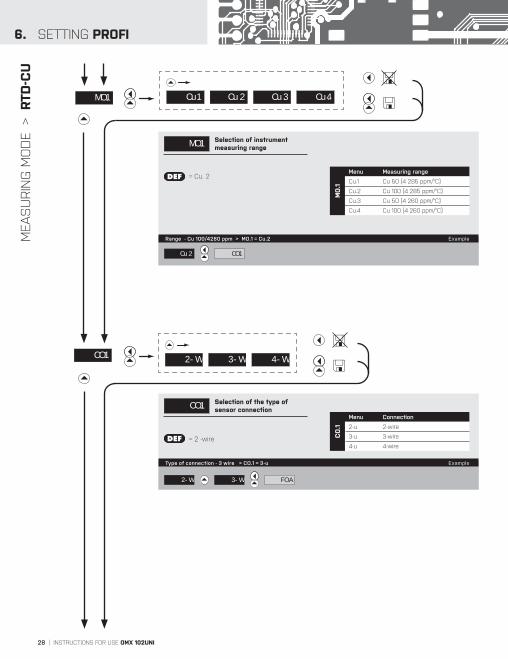
MO.1 Selection of instrument measuring range
DEF = Cu. 2
MO
.1
Menu Measuring range
Cu.1 Cu 50 (4 285 ppm/°C)
Cu.2 Cu 100 (4 285 ppm/°C)
Cu.3 Cu 50 (4 260 ppm/°C)
Cu.4 Cu 100 (4 260 ppm/°C)
Range - Cu 100/4260 ppm > MO.1 = Cu.2 Example
Cu .2 CO.1
CO.1 Selection of the type of sensor connection
DEF = 2 -wire CO
.1
Menu Connection
2-u 2-wire
3-u 3-wire
4-u 4-wire
CO.1
Type of connection - 3 wire > CO.1 = 3-u Example
2-W
2-W 3-W 4-W
3-W FO.A

INSTRUCTIONS FOR USE OMX 102UNI | 29
6.SETTING PROFI
FO.A Setting projection of the decimal point
- positioning of the DP is set here in the measuring mode
DEF = FL.P.
MEA
SU
RIN
G M
OD
E >
R
TD-C
U
38
Projection of DP on display > 000 Example
FO.A
MNU *subsequent item on the menu depends on instrument equipment
000 00.o 0.oo FL.P.
FL.P. 000

30 | INSTRUCTIONS FOR USE OMX 102UNI
5-1 6-1 510 610
SETTING LIGHT5.M
EAS
UR
ING
MO
DE
> R
TD-N
i
MO.1
MO.1 Selection of instrument measuring range
DEF = Ni 1 000 - 5 000 ppm/°C MO
.1
Menu Measuring range
5-1 Ni 1 000 (5 000 ppm/°C)
6-1 Ni 1 000 (6 180 ppm/°C)
510 Ni 10 000 (5 000 ppm/°C)
610 Ni 10 000 (6 180 ppm/°C)
Range - Ni 10 000, 5 000 ppm > MO.1 = 510 Example
5-1 6-1 CO.1510
CO.1 Selection of the type of sensor connection
DEF = 2 -wire CO
.1
Menu Connection
2-u 2-wire
3-u 3-wire
4-u 4-wire
CO.1
Type of connection - 3 wire > CO.1 = 3-u Example
2-W
2-W 3-W 4-W
3-W FO.A

INSTRUCTIONS FOR USE OMX 102UNI | 31
FO.A Setting projection of the decimal point
- positioning of the DP is set here in the measuring mode
DEF = FL.P.
MEA
SU
RIN
G M
OD
E >
R
TD-N
i
5.SETTING LIGHT
38
Projection of DP on display > 000 Example
FO.A
MNU *subsequent item on the menu depends on instrument equipment
000 00.o 0.oo FL.P.
FL.P. 000

32 | INSTRUCTIONS FOR USE OMX 102UNI
SETTING LIGHT5.M
EAS
UR
ING
MO
DE
> T/
C
Type of thermocouple “N” Example
MO.1
K
MO.1 Selection of the type of thermocouple
DEF = Type “K”
MO
.1
Menu Type of thermocouple
B T/C B
E T/C E
J T/C J
K T/C K
N T/C N
R T/C R
S T/C S
T T/C T
L T/C L
CO.1
B E J K
R S TN
N
>
>
CO.1 Selection of the type of sensor connection
DEF = EX. 1
CO
.1
Menu Connection Ref. T/C
IN.1 measuring C.J. at instru-ment brackets
IN.2
measuring C. J. at instrument brackets with ant i -ser ies connected ref. TC
EX.1the entire measuring set is working under invaried and constant temperature
EX.2 when using compensa-tion box
CO.1IN.1 IN.2 EX.1
Selection of the type of sensor connection > CO.1 = EX.2 Example
EX.1 EX.2 C.J.1
EX.2
Method and procedure of setting the cold junctions is described in separate chapter on page 82
!For thermocoule type “B” the items “CO.1” and “C.J.1” are not available
!
L

INSTRUCTIONS FOR USE OMX 102UNI | 33
FO.A Setting projection of the decimal point
- positioning of the DP is set here in the measuring mode
DEF = FL.P.
MEA
SU
RIN
G M
OD
E >
T/
C
5.SETTING LIGHT
C.J.1 23Setting temperature of cold junction
C.J.1 Setting temperature of cold junction
- rrange 0…99°C with compensation boxDEF = 23
Setting temperature of cold junction > C.J.1 = 35 Example
23 25 24 35 25 FO.A
38
Projection of DP on display > 000 Example
FO.A
MNU *subsequent item on the menu depends on instrument equipment
000 00.o 0.oo FL.P.
FL.P. 000

34 | INSTRUCTIONS FOR USE OMX 102UNI
SETTING LIGHT5.M
EAS
UR
ING
MO
DE
> D
U
MA.A Setting display projection for maximum value of input
signal
- range of the setting: -99M…999M
- position of the DP does not affect display projection
- the DP is automatically shifted after the value is confirmed
DEF = 100
MIN Setting display projection for minimum value of input signal
- range of the setting: -99M…999M
- position of the DP does not affect display projection
- the DP is automatically shifted after the value is confirmed
DEF = 0
Projection for the beginning > MI.A = 0 Example
Projection for the end > MA.A = 250 Example
0Setting for minimum input signalMI.A
100Setting for maximum input signal
MA.A
0 MA.A
100 110 100
150
140 130 120
150 FO.A 250

INSTRUCTIONS FOR USE OMX 102UNI | 35
FO.A Setting projection of the decimal point
- positioning of the DP is set here in the measuring mode
DEF = FL.P.
MEA
SU
RIN
G M
OD
E >
D
U
5.SETTING LIGHT
Calibration of the beginning and the end of range of linear potentiometer is on page 39 38
Projection of DP on display > 000 Example
FO.A
MNU *subsequent item on the menu depends on instrument equipment
000 00.o 0.oo FL.P.
FL.P. 000

36 | INSTRUCTIONS FOR USE OMX 102UNI
SETTING LIGHT5.D
ISPLA
YED
ON
LY W
ITH
OPTI
ON
S >
CO
MPA
RATO
RS
L.1 Setting boundaryfor limit 1
- range of the setting: -99M…999M
- contingent modification of hysteresis or delay may be performed in “PROFI” menu
DEF = 25
DEF „Hystresis”=0, „Delay”=0
L.2 Setting boundaryfor limit 2
- range of the setting: -99M…999M
- contingent modification of hysteresis or delay may be performed in “PROFI” menu
DEF = 75
DEF „Hystresis”=0, „Delay”=0
L.2
L.1 25Setting boundaryfor limit 1
75Setting boundaryfor limit 2
Setting limit 2 > L. 2 = 205 Example
Setting limit 1 > L. 1 = 30 Example
*subsequent item on the menu depends on instrument equipment
25 26 20 29 28 27
20 30 MNU.
75 75 105 05 95 85
205 MNU.
*subsequent item on the menu depends on instrument equipment
Items for “Limits” and “Analog output” are accessible only if incorporated in the instrument.
!

INSTRUCTIONS FOR USE OMX 102UNI | 37
D
ISPLA
YED
ON
LY W
ITH
OPTI
ON
S >
AN
ALO
G O
UTP
UT
5.SETTING LIGHT
T.A.1 Setting the type of analog output
T.A
.1
Menu Range Description
I20 0…20 mA
E.T.4 4…20 mA with error message indication and broken loop indication (<3,6 mA)
T 4 4…20 mA with broken loop indication (<3,6 mA)
E. 4 4…20 mA with indication of error statement (<3,6 mA) DEF I 4 4…20 mA
I 5 0…5 mA
u 2 0…2 V
u 5 0…5 V
u10 0…10 V
-10 ±10 V
FRE. 0,2…2200 Hz
A.L.1 Assigning the display value to the beginning of the AO
range
- range of the setting: -99M…999MDEF = 0
Display value for the beginning of the AO range > A.L.1 = 0 Example
T.A.1 I20 E.T.4 T. 4 u10 -10
0
Assigning the display value to the beginning of the AO range
A.L.1
FRE.
A.H.1 Assigning the display value to the end of the AO range
- range of the setting: -99M…999MDEF = 100
A.H.1 100
Assigning the display value to the end of the AO range
Display value for the end of the AO range > A.H.1 = 120 Example
0 A.H.1
100 100 120 110 MNU
Type of analog output - 0...10 V > T.A.1 = U 10 Example
I 4 u 2 I 5 u 10 u 5 A.L.1
• • •

38 | INSTRUCTIONS FOR USE OMX 102UNI
5. SETTING LIGHT
MNU
MNU Setting the menu typeLIGHT/PROFI
LIG > menu LIGHT, a simple menu, which contains only the most essential items necessary for instrument setting
> linear tree structure
PRO > menu PROFI, a complete menu for complete instrument setting
> tree menu structure
DEF = LIGHT
LIG PRO
SET.
RES. Restoration of manufacture instrument setting
- in the event of error setting the manufacture setting may be restored
- restoration is performed for the currently selected type of the instrument input (select “FIR.”)
- provided you stored your user setting in the “PROFI” menu, it may also be restored (select “USR.”)
- loading manufacture calibration and primary setting of items on the menu (DEF)
Restoration of manufacture setting > FIR. Example
SET. LNG.FIR.* subsequent item on the menu depends on instrument equipment
FIR. USR.
Type „DC“ 40
Type “PM” 40
Type “OHM“ 40
Type “RTD-Pt“ 40
Type “RTD-Ni“ 40
Type “T/C“ 40
Type “DU” 39
Typ. “RTD-Cu“ 40
RE.C. Restoration of manufacture calibration
- in the event of error calibration it is feasible to restore manufacture calibration
- Prior to execution of any modifications you will be asked to confirm your selection (YES)
RE.C.
Restoration of manufacture calibration > YES Example
RE.C. SET.
YES
YES
Menu LIGHT > MNU. = LIG. Example
LIG RE.C.

INSTRUCTIONS FOR USE OMX 102UNI | 39
SETTING LIGHT 5.
C.L.1 Calibration of input range - the potentiometer traveller in
initial position
- prior confirming the flashing “YES” sign the potentiometer traveller has to be in given idle position
C.H.1 Calibration of input range - the potentiometer traveller
in end position
- prior confirming the flashing “YES” sign the potentiometer traveller has to be in given idle position
Calibration of the end of the range > C.L.1 Example
Calibration of the beginning of the range > C.L.1 Example
C.H.1 YES
flashing legend
C.L.1 YES
flashing legend
YES C.H.1
Only for type “DU”
YES LNG.
Only for type “DU”

40 | INSTRUCTIONS FOR USE OMX 102UNI
5. SETTING LIGHT
0Setting new access passwordP.LI.
P.LI. Setting new access password
- access password for menu LIGHT
- range of the number code 0…999
- upon setting the password to “000” the access to menu LIGHT is free without prompt to enter it
- in case the password is lost, please contact the adminstrator of this device
DEF = 0
New password - 341 > P.LI. = 341 Example
0
ID.
1 01 11 21 31
41 041 341 241 141
LNG.
LNG. Selection of language in instrument menu
- selection of language version of the instrument menu
DEF = ENG.
Language selection - ENGLISH > LNG. = ENG. Example
ENG. P.LI.
CZ ENG.

INSTRUCTIONS FOR USE OMX 102UNI | 41
SETTING LIGHT 5.
ID.
ID. Instrument SW version
- the display shows the type of instrument indication, SW number, SW version and current input setting (Mode)
- if SW version contains a letter in first position, then it is a customer SW
- after the identification is completed the menu is automatically exited and the instrument restores the measuring mode
YES OMX 102UNI 61-008
setting the input typeSW: version
PM
instrument type
142 Return to measuring mode

42 | INSTRUCTIONS FOR USE OMX 102UNI
SETTING PROFI6.
SETTINGPROFIFor expert usersComplete instrument menuAccess is password protectedPossibility to arrange items of the USER MENUTree menu structure
6.0 SETTING “PROFI”
PROFI Complete programming menu • contains complete instrument menu and is protected by optional number code • designed for expert users • preset from manufacture is menu LIGHT
Switching over to “PROFI” menu
• access to PROFI menu • authorization for access to PROFI menu does not depend on setting under item SER. > MNU.
• password protected access (unless set as follows under the item SER. > N.PA. > PROFI =0)
• access to menu selected under item SER. > MNU. > LIGHT/PROFI • password protected access (unless set as follows under the item SER. > N.PA. > LIGHT =0)
• for access to LIGHT menu passwords for LIGHT and PROFI menu may be used
> 2s
< 2s

INSTRUCTIONS FOR USE OMX 102UNI | 43
6.SETTING PROFI

44 | INSTRUCTIONS FOR USE OMX 102UNI
SETTING PROFI6.
6.1 SETTING “PROFI” - INPUT
6.1.1 RESETTING INTERNAL VALUES
+
CLR.
CHA.
SER.
OUT.
CFG.
EXT.
INP.
RTC.
The primary instrument parameters are set in this menu
CLR. Resetting internal values
CFG. Selection of measuring range and parameters
RTC. Setting date and time for option with RTC
EXT. Setting external inputs functions
+
CHA.
SER.
OUT.
CLR.
CFG.
EXT.
INP. C.T.A
RTC.
C.T.B
C.A.T.
CLR. Resetting internal values
C.T.A Tare resetting - Channel A
C.T.B Tare resetting - Channel A
C.A.T. Tare resetting on both channels simultaneously
Only for DC, PM and DU types
!

INSTRUCTIONS FOR USE OMX 102UNI | 45
6.SETTING PROFI
6.1.2a SELECTION OF MEASURING RATE
6.1.2a SELECTION OF THE NUMBER OF ACTIVE INPUTS
+
CHA.
SER.
OUT.
CLR.
RTC.
CFG.
EXT.
INP.
INP.
M.P.S.
IN.1
T.SW.
IN.2
SWI. DEF
160
80
20
40
10
5.0
2.5
0.5
1.2
M.P.S. Selection of measuring rate
160 160 measurements/s
80 80 measurements/s
40 40 measurements/s
20 20 measurements/s
10 10 measurements/s
5.0 5 measurements/s
2.5 2,5 measurements/s
1.2 1,2 measurements/s
0.5 0,5 measurements/s
+
CHA.
SER.
OUT.
CLR.
RTC.
CFG.
EXT.
INP. M.P.S.
INP.
IN.1
T.SW.
IN.2
SWI.
DEF1.IN.
2.IN.
INP. Selection of the number of active inputs
- this menu item is accessible only in the 2-input version of the device
1.IN. Active input 1
2.IN. Active inputs 1 and 2

46 | INSTRUCTIONS FOR USE OMX 102UNI
SETTING PROFI6.
Access password142 PAS. 0
INP. CHA.
FO.A 000 00.o 0.oo FL.P.
MD.A
C. A 0
OFF AVR. RND.FI.A
Programming sch
DC
PM
T/C
CLR. C.T.A . C.T.B C.A.T.
CFG. M./.S. 0.5 1.2 2.5 50 100 160
RTD
EXT.
DC PM T/C DU
INP. 1.IN. 2.IN.
SWI. MAN. AUT.
IN.1
T.SW.
EX.1 OFF LOC. HLD.. TR.A C. M. SWP.
RTC. TIM.
DAT. ROK
MES.
DEN
00
RTC.
MIN.
SEC.
00
2
T. 1
MO.1
CO.1 IN.1 IN.2 EX.1 EX.2.
0
R.A.1
C.J.1
LE.1
0
23 T/C
CO.1 2-W. 3-W. 4-W.
T/C
IN.2 T. 2 Setting is identical with “IN.1”
EX.2 OFF LOC. HLD.. TR.A C. M. SWP.
E0.1 E0.5 R.05 R0.1
Cu.1 Cu.2 Cu.3 Cu.4
B E J S T L
5-1 6-1 510 610
20m u80 i0.1 i0.2
0.1 0.3 24.0 30.0
u 2 u 5 I 4 E 4
C. A
MA.A 100
MI.A 0SE.A
P.T.A 0
DE.A 0
FR.A -99M
SV.ALO.A
TO.A 999M
NO ALL IN OUT
C. B Setting is identical with “C. A”
FO.M 000 00.o 0.oo FL.P.
M.FN.
M.MF.
C. A 0
FR.M -99M
SV.MLO.M
TO.M 999M
K. F 0
NO ALL IN OUT
DE.M 0
I.MF. NO C. A F. A C. B F. B
MUL. 1/P SUM. DIV..
M . M. I.M .M . NO C. A F. A C. B F. B
> 2s
OHM
Cu
Ni
RTDOHM Ni Cu
RTDOHM Ni Cu
RTDOHM
Ni Cu
- after setting in item “MENU”> 2s

INSTRUCTIONS FOR USE OMX 102UNI | 47
6.SETTING PROFI
OUT. SER.
CH.2
CAL. CH.1
DU
heme PROFI MENU
MNU. LIG. PRO.
USR.
SAV.
ID. OMX 102UNI. . . .
YES
YES
SET.
RES.
FIR.
OB.K YES
LNG. LIG. PRO.
P.PR.
N.PA. P.LI. 0
0
C.L.1 YES
C.H.1 YES
C.L.2 YES
C.H.2 YES
A. O.
DIS. B. L. NO YES TIM.
A. 2
40A.H.1
100F.H.1
0A.L.1
F.L.1 0
T.A.1 I20 E.T4 T. 4 E. 4 I 4 I 5 u 2 u 5 u10 -10 FRE.
NO C. A F. A C. B F. B M.FN. MIN MAXI.A.1A. 1
DAT. BD 0.6 1.2 2.4 1152 230
ADD. 0
GSD 1CH. 5CH. 9CH. 1.K.L 5.K.L 5.K.L
PRO. ASC. M.BS. MOD.
LIM. L. 1
L. 2
H. 1 0
L. 1 20
0ON.1
TYP. CLO. OPE.
NO C. A F. A C. B F. B M.FN. MIN MAXI.A.1
HYS. F-T DOS. ERR.MOD.
0OF.1
0P. 1
0T. 1
5V 12V 17V 24VEXC.
MEM. SWI.
STR.
STO.
PER.
TRG.
Upon delay exceeding 60 s the programming mode is automatically discontinued and the instrument itself restores the measuring mode
!

48 | INSTRUCTIONS FOR USE OMX 102UNI
SETTING PROFI6.
6.1.2c SELECTION OF INPUTS SWITCHING
6.1.2d SETTING THE PERIOD FOR INPUTS SWITCHING
+
CHA.
SER.
OUT.
CLR.
RTC.
CFG.
EXT.
INP. M.P.S.
SWI.
IN.1
T.SW.
IN.2
INP.
DEFMAN.
AUT.
SWI. Selection of inputs switching
- this menu item is accessible only in the 2-input version of the device
MAN. Manual inputs switching
- inputs switching is controlled by selected key on the front panel or selected external input
AUT. Automatic inputs switching
- inputs switching is automatic in a time period set in “T.SW.”
+
CHA.
SER.
OUT.
CLR.
RTC.
CFG.
EXT.
INP. M.P.S.
T.SW.
IN.1
SWI.
IN.2
INP.
DEF2.0
SWI. Setting the period for inputs switching
- setting the time period for projection of channels in automatic mode ode of inputs switching (“AUT.”)
- range of the setting: 0,5…99,5 s (step 0,5)
- DEF T.SW. = 2 s
INSTRUCTIONS FOR USE OMX 102UNI | 49
6.SETTING PROFI
6.1.2e SELECTION OF „INSTRUMENT“ TYPE FOR CHANNEL 1
+
CHA.
SER.
OUT.
CLR.
RTC.
CFG.
EXT.
INP.
INP.
IN.1
M.P.S.
T.SW.
IN.2
SWI.
DEF
OHM
PM
DC
Pt
NI
CU
TC
DU
MO.1
T. 1
LE.1
R.A.1
C.J.1
CO.1
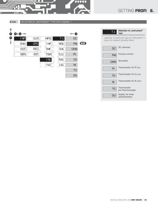
T. 1 Selection of „instrument“ type
- selection of particular type of “instrument” is bound to relevant dynamic items
DC DC voltmeter
PM Process monitor
OHM Ohmmeter
Pt Thermometer for Pt xxx
Cu Thermometer for Cu xxx
Ni Thermometer for Ni xxxx
TC Thermometerpro thermocouples
DU Display for linear potentiometers

50 | INSTRUCTIONS FOR USE OMX 102UNI
SETTING PROFI6.
6.1.2f SELECTION OF MEASURING RANGE FOR CHANNEL 1
+
CHA.
SER.
OUT.
CLR.
RTC.
CFG.
EXT.
INP.
INP.
IN.1
M.P.S.
T.SW.
IN.2
SWI.
T. 1
MO.1
LE.1
R.A.1
C.J.1
CO.1
PM
i 0.
25
5. A
1. A
50
102DC
100
200
400
DEF
Ni
5-1
6-1
DEF
Cu
Cu.1
Cu .4
Cu .3
Cu .2
DEF
B
R
N
K
J
E
T
S
T/C
DEF
L
Pt
E0.1
r0.1
r.05
DEF
U0.1
E1.0
E0.5
610
510
u 5
u 2
u10
I 0
I 4
E 4
DEF
PM
u80
i0.2
i0.1
u1
60m
30m
DC
u20
u40
OHM
0.1
30
24
DEF
3.0
1.5
0.3
MOD. Selection of instrument measuring range
OM
X 1
02
DC
Menu Measuring range
1. A ±1 A
5. A ±5 A
25 ±25 V
50 ±50 V
100 ±100 V
200 ±200 V
400 ±400 V
Menu Measuring range
30m ±30 mV
60m ±60 mV
u 1 ±1 V
DC u20 ±20 V
u40 ±40 V
u80 ±80 V
i0.1 ±90 mA
i0.2 ±180 mA
PM
Menu Measuring range
u 2 ±2 V
u 5 ±5 V
u10 ±10 V
I 5 ±5 mA
I 0 ±20 mA
I 4 4…20 mA
E 44…20 mA, with error statement of „underfl ow“ upon signal smaller than 3,36 mA
Menu Measuring range O
HM
0.1 0…100 Ω
0.3 0…300 Ω
1.5 0…1,5 Ω
3.0 0…3 kΩ
24 0…24 kΩ
30 0…30 kΩ
RTD
Menu Measuring range
E0.1 Pt 100 (3 850 ppm/°C)
E0.5 Pt 500 (3 850 ppm/°C)
E1.0 Pt 1000 (3 850 ppm/°C)
U0.1 Pt 100 (3 920 ppm/°C)
R.05 Pt 50 (3 910 ppm/°C)
R0.1 Pt 100 (3 910 ppm/°C)
Menu Measuring range
NI
5-1 Ni 1 000 (5 000 ppm/°C)
6-1 Ni 1 000 (6 180 ppm/°C)
510 Ni 10 000 (5 000 ppm/°C)
610 Ni 10 000 (6 180 ppm/°C)
CU
Menu Measuring range
Cu.1 Cu 50 (4 280 ppm/°C)
Cu.2 Cu 1 00 (4 280 ppm/°C)
Cu.3 Cu 50 (4 260 ppm/°C)
Cu.4 Cu 100 (4 260 ppm/°C)
T/C
Menu Type of thermocoupleB T/C B
E T/C E
J T/C J
K T/C K
N T/C N
R T/C R
S T/C S
T T/C T
L T/C L

INSTRUCTIONS FOR USE OMX 102UNI | 51
6.SETTING PROFI
6.1.2g SELECTION OF THE TYPE OF SENSOR CONNECTION FOR CHANNEL 1 RTD OHM T/C
+
CHA.
SER.
OUT.
CLR.
RTC.
CFG.
EXT.
INP.
INP.
IN.1
M.P.S.
T.SW.
IN.2
SWI.
T. 1
CO.1
LE.1
R.A.1
MO.1
DEF
4-w
3-w
2-w
CO.1 Selection of the type of sensor connection
RTD OHM
2-w 2-wire connection
3-w 3-wire connection
4-w 4-wire connection
T/C
IN.1 Measurement without reference thermocouple
- measuring cold junction at instrument brackets
IN.2 Measurement with reference thermocouple
- measuring cold junction at instrument brackets with anti-series connected reference thermocouple
EX.1 Measurement without reference thermocouple
- the entire measuring set is working under invaried and constant temperature
EX.2 Measurement with reference thermocouple
- when using compensation box
Method and procedure of setting the cold junctions is described in separate chapter on page 82
!
For thermocoule type „B” the items „CO.1” and „C.J.1” are not available
!
+
CHA.
SER.
OUT.
CLR.
RTC.
CFG.
EXT.
INP.
INP.
IN.1
M.P.S.
T.SW.
IN.2
SWI.
T. 1
CO.1
C.J.1
MO.1
DEF
Ex.1
In .2
In .1
Ex.2
52 | INSTRUCTIONS FOR USE OMX 102UNI
SETTING PROFI6.
6.1.2h SETTING TEMPERATURE OF COLD JUNCTION FOR CHANNEL 1 T/C
6.1.2i ZERO OFFSET OF THE MEASUREMENT RANGE FOR CHANNEL 1 RTD OHM
6.1.2j COMPENSATION OF 2-WIRE CONDUCT FOR CHANNEL 1 RTD OHM
+
CHA.
SER.
OUT.
CLR.
RTC.
CFG.
EXT.
INP.
INP.
IN.1
M.P.S.
T.SW.
IN.2
SWI.
T. 1
C.J.1
CO.1
MO.1
DEF23
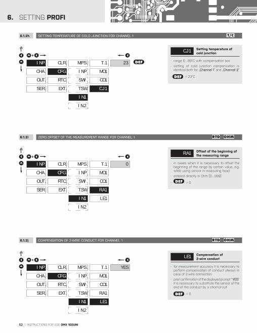
C.J.1 Setting temperature of cold junction
- range 0…99°C with compensation box
- setting of cold junction compensation is identical both for „Channel 1“ and „Channel 2“
- DEF = 23°C
+
CHA.
SER.
OUT.
CLR.
RTC.
CFG.
EXT.
INP.
INP.
IN.1
M.P.S.
T.SW.
IN.2
SWI.
T. 1
R.A.1
LE.1
CO.1
MO.1
0
R.A.1 Offset of the beginning of the measuring range
- in cases when it is necessary to offset the beginning of the range by certain value, e.g. while using sensor in measuring head
- entered directly in Ohm (0…999)
- DEF = 0
+
CHA.
SER.
OUT.
CLR.
RTC.
CFG.
EXT.
INP.
INP.
IN.1
M.P.S.
T.SW.
IN.2
SWI.
T. 1
LE.1
R.A.1
CO.1
MO.1
YES
LE.1 Compensation of 2-wire conduct
- for measurement accuracy it is necessary to perform compensation of conduct always in case of 2-wire connection
- prior confirmation of the displayed prompt “ YES“it is necessary to substitute the sensor at the end of the conduct by a short-circuit
- DEF = 0
INSTRUCTIONS FOR USE OMX 102UNI | 53
6.SETTING PROFI
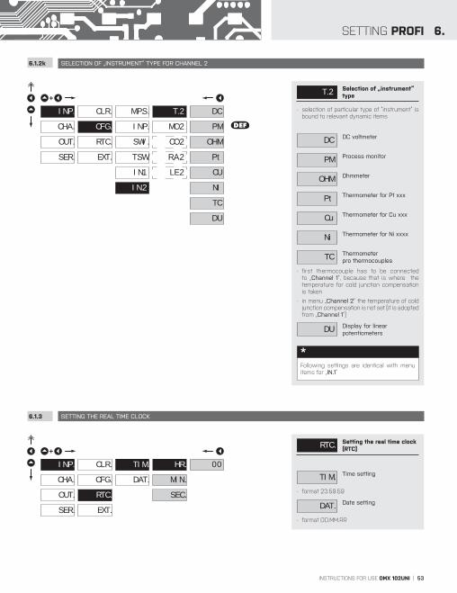
6.1.2k SELECTION OF „INSTRUMENT“ TYPE FOR CHANNEL 2
6.1.3 SETTING THE REAL TIME CLOCK
+
CHA.
SER.
OUT.
CLR.
RTC.
CFG.
EXT.
INP.
INP.
IN.2
M.P.S.
T.SW.
IN.1
SWI.
DEF
OHM
PM
DC
Pt
NI
CU
TC
DU
MO.2
T. 2
LE.2
R.A.2
CO.2
T. 2 Selection of „instrument“ type
- selection of particular type of “instrument” is bound to relevant dynamic items
DC DC voltmeter
PM Process monitor
OHM Ohmmeter
Pt Thermometer for Pt xxx
Cu Thermometer for Cu xxx
Ni Thermometer for Ni xxxx
TC Thermometerpro thermocouples
- first thermocouple has to be connected to „Channel 1“, because that is where the temperature for cold junction compensation is taken
- in menu „Channel 2“ the temperature of cold junction compensation is not set (it is adopted from „Channel 1“)
DU Display for linear potentiometers
Following settings are identical with menu items for „IN.1”
*
+
CHA.
SER.
OUT.
CLR.
CFG.
RTC.
EXT.
INP.
DAT.
TIM.
SEC.
MIN.
00HR.
RTC. Setting the real time clock (RTC)
TIM. Time setting
- format 23.59.59
DAT. Date setting
- format DD.MM.RR
54 | INSTRUCTIONS FOR USE OMX 102UNI
SETTING PROFI6.
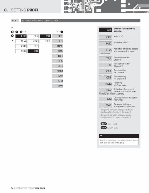
6.1.4 EXTERNAL INPUT FUNCTION SELECTION
+
CHA.
SER.
OUT.
CLR.
CFG.
EXT.
RTC.
INP.
EX.2
EX.1
B.PA.
HLD.
OFF
TR.A
TR.B
C.T.A
C.T.B
N.M.M.
SAV.
C. M.
SWP.
EXT. External input function selection
OFF Input is off
HLD. Activation of HOLD
B.PA. Activation of locking access into programming menu
LIGHT/PROFI
TR.A Tare activation for Channel 1
TR.B Tare activation for Channel 2
C.T.A Tare resetting for Channel 1
C.T.B Tare resetting for Channel 2
N.M.M. Resettingmin/max value
SAV. Activation of measured data record in instrument
memory for option FAST/RTC
C. M. Clearing memory for option FAST/RTC
SWP. Swapping between analogue inputs/outputs
- Swapping between analogue outputs (configuration: 1x input > 2x output)
- Swapping between analogue inputs (configuration: 2x input > 1x output)
- DEF EX.1 > HLD.
- DEF EX.2 > B.PA.
Identical procedure to the one shown above can also be applied to „EX.2”
*

INSTRUCTIONS FOR USE OMX 102UNI | 55
6.SETTING PROFI

56 | INSTRUCTIONS FOR USE OMX 102UNI
SETTING PROFI6.
6.2 SETTING “PROFI” - CHANNELS
6.2.1a DISPLAY PROJECTION FOR CHANNEL 1 DC AC PM DU OHM
6.2.1b SETTING FIXED TARE FOR CHANNEL 1 DC AC PM DU OHM
M.FN.
CHA.
SER.
OUT.
C. A
C. B
INP.
+
M. M.
In this section of the menu input parame-ters are set
C. A Setting of parameters of measuring input “Channel 1”
C. B Setting of parameters of measuring input “Channel 2”
M.FN. Setting of parameters of mathematical functions
M. M. Selecting the input for evaluating the Min/Max
value
CHA.
SER.
OUT.
C. A
C. B
INP.
M.FN.
MA.A
MI.A 0
+
SE.A
FI.A
LO.A
DE.A
P.T.AFO.A
M. M.
SE.A Setting display projection
MI.A Setting display projection for minimum value of input
signa
- range of the setting: -99M…999M
- DEF = 0
MA.A Setting display projection for maximum value of
input signal
- range of the setting: -99M…999M
- DEF = 100
FO.A
CHA.
SER.
OUT.
C. A
C. B
INP.
M.FN.
MA.A
MI.A 0
+
SE.A
FI.A
LO.A
DE.A
P.T.A
M. M.
SE.A Setting “Fixed tare” value
- setting is designed for the event when it is necessary to firmly shift the beginning of the range by known size
- when setting (P.T.A≠0) is in effect, display does not show the “T” symbol
- range of the setting: -99M…999M
- DEF = 0
Setting is identical with channel „C. B”
!

INSTRUCTIONS FOR USE OMX 102UNI | 57
6.SETTING PROFI
6.2.1c DIGITAL FILTERS FOR CHANNEL 1
CHA.
SER.
OUT.
C. A
C. B
INP.
M.FN.
C. A
OFF
+
FI.A
SE.A
LO.A
DE.A
MD.A
AVR.
FLO.
EXP.
RND.
FO.A
M. M.
FI.A Selection of digital filters
- at times it is useful for better user projection of data on display to modify it mathematically and properly , wherefore the following filters may be used
OFF Filters are off
AVR. Measured data average
- arithmetic average from given number „C. A“ of measured values
- range 2…100
FLO. Selection of floating filter
- floating arithmetic average from given number „C. A“ of measured data and updates with each measured value
- range 2…30
EXP. Selection of exponential filter
- integration filter of first prvního grade with time constant „C. A“ measurement
- range 2…100
RND. Measured value rounding
- is entered by any number, which determines the projection step (e.g: “C. A”=2,5 > display 0, 2.5, 5,...)
C. A Setting constants
- this menu item is always displayed after selection of particular type of filter
- DEF = 2
Setting is identical with channel „C. B”
!
40
60
20
80
100
Floating filterConstant F.A = 5.0
36 36
52 52
68 68
8484
Arithmetic averangeConstant F.A = 5.0
Exponential filterConstant F.A = 5.0
40
60
20
80
100
40
60
20
80
100
40
60
20
80
100
36
4959
6774
7983 86 89
75
6455
4238
34 31 2927
5 10 2015
5 10 2015
5 10 2015
5 10 2015
Input value
t
t
t
t

58 | INSTRUCTIONS FOR USE OMX 102UNI
SETTING PROFI6.
6.2.1d PROJECTION FORMAT - POSITIONING OF DECIMAL POINT FOR CHANNEL 1
6.2.1e SELECTION OF STORING DATA INTO INSTRUMENT MEMORY FOR CHANNEL 1
CHA.
SER.
OUT.
C. A
C. B
INP.
M.FN.
+
FI.A
SE.A
LO.A
DE.A
FO.A
000.
00.o
0.oo
FL.P.M. M.
FO.A Selection of decimal point
- the instrument allows for classic projection of a number with positioning of the DP as well as projection with floating DP, allowing to display a number in its most exact form „FL.P.“
000 Setting DP - XXX
00.o Setting DP - XX.x
0.oo Setting DP - X.xx
FL.P. Floating DP
CHA.
SER.
OUT.
C. A
C. B
INP.
M.FN.
+
FI.A
SE.A
DE.A
NO
ALL
IN
M. M.
SV.A
FO.A
LO.A
FR.A
TO.A
OUT
LO.A Selection of storing data into instrument memory
- by selection in this item you allow to register values into instrument memory
- another setting in item “OUT. > MEM.” (not in standard experiment)
NO Measured data is not stored
ALL Measured data is stored in memory
IN Only data measured within the set interval is stored
in memory
OUT Only data measured outside the set interval is stored
in memory
FR.A Setting the initial interval value
- range of the setting: -99M…999M
- DEF = -99M
TO.A Setting the final interval value
- range of the setting: -99M…999M
- DEF = 999M
Setting is identical with channel „C. B”
!
Setting is identical with channel „C. B”
!

INSTRUCTIONS FOR USE OMX 102UNI | 59
6.SETTING PROFI
6.2.1f PROJECTION OF DESCRIPTION - THE MEASURING UNITS FOR CHANNEL 1
CHA.
SER.
OUT.
C. A
C. B
INP.
M.FN.
+
FI.A
SE.A
LO.A
000
M. M.
FO.A
DE.A
DE.A Setting projection of description
- 3 characters can be added to standard numerical formats
- setting is realised using modified ASCII code, where upper number defines position of the character, bottom line at the first position displays the charater and at the last two positions show the code of the character in interval 0…95.
- description is cancelled by code 000
- RTD T/C DEF = °C
- DC PM DU OHM DEF = none
Table of signs on page 86
!
Setting is identical with channel „C. B”
!
Description position
INPUT
OUTPUT
ASCII symbol code
Set description

60 | INSTRUCTIONS FOR USE OMX 102UNI
SETTING PROFI6.
6.2.2a MATHEMATIC FUNCTIONS - INPUT SELECTION
CHA.
SER.
OUT. M.FN.
C. B
INP. C. A
+
M. M.
I.MF.
FO.M
C. B
C. C
C. F
C. E
C. D
C. A
DE.M
M.FN.
LO.M
NO
C. A
F. A
C. B
F. B
A.CH.
A. F.
I.MF. Selection of input for calculation of mathematic
function
- selection of value from which the mathematic function will be calculated
NO Mathematic functions are off
C. A From “Channel A”
F. A From “Channel A” after modification by digital filter
C. B. From “Channel B”
F. B From “Channel B” after modification by digital filter
A.CH. From “Channels A, B“
A. F. From “Channels A, B,” after modification by digital filters

INSTRUCTIONS FOR USE OMX 102UNI | 61
6.SETTING PROFI
6.2.2b MATHEMATIC FUNCTIONS
CHA.
SER.
OUT. M.FN.
C. B
INP. C. A
+
M. M.
M.FN.
FO.M
C. B
C. C
C. F
C. E
C. D
C. A
DE.M
I.MF.
LO.M
MUL.
1/M.
LOG.
EXP.
POW.
RT.
SIN.
SUM
DIV.
M.FN. Selection of mathematic functions
On selecting „From chan. A/B“ in item „V.MF.“
MUL. Multinominal
FExDxCxBxAx 2345
1/M. 1/x
FxE
xD
xC
xB
xA5
234
LOG. Logarithm
FEDxCBx
A
ln
EXP. Exponential
FeA EDxCBx
POW. Power
FCBxA EDx
RT. Root
FEDxCBx
A
On selecting „From chan. A+B” in item „V.MF.“
SUM Sum of the values from channels (inputs)
(A x KA + B x KB + C x KC + D x KD) x E + F
DIV. Quotient of values from channels (inputs)
(A x KA + C x KC) /(B x KB + D x KD) x E + F
C. - Setting constants for calculation of mat.functions
- this menu is displayed only after selection of given mathematic function

62 | INSTRUCTIONS FOR USE OMX 102UNI
SETTING PROFI6.
6.2.2c PROJECTION FORMAT - POSITIONING OF DECIMAL POINT
6.2.2d MATHEMATIC FUNCTIONS - SELECTION OF STORING DATA INTO INSTRUMENT MEMORY
CHA.
SER.
OUT. M.FN.
C. B
INP. C. A
+
M. M.
M.FN.
C. B
C. C
C. F
C. E
C. D
C. A
DE.M
I.MF.
LO.M
000.
00.o
0.oo
FL.P.
FO.M.
FO.M Selection of decimal point
- the instrument allows for classic projection of a number with positioning of the DP as well as projection with floating DP, allowing to display a number in its most exact form „FL.P.“
000 Setting DP - XXX
00.o Setting DP - XX.x
0.oo Setting DP - X.xx
FL.P. Floating DP
CHA.
SER.
OUT. M.FN.
C. B
INP. C. A
+
M. M.
M.FN.
C. B
C. C
C. F
C. E
C. D
C. A
DE.M
I.MF.
FO.M
NO
ALL
IN
SV.M
FR.M
TO.M
OUT
LO.M
LO.M Selection of storing data into instrument memory
- by selection in this item you allow to register values into instrument memory
- another setting in item “OUT. > MEM.” (not in standard experiment)
NO Measured data is not stored
ALL Measured data is stored in memory
IN Only data measured within the set interval is stored
in memory
OUT Only data measured outside the set interval is stored
in memory
FR.M Setting the initial interval value
- range of the setting: -99M…999M
- DEF = -99M
TO.M Setting the final interval value
- range of the setting: -99M…999M
- DEF = 999M
INSTRUCTIONS FOR USE OMX 102UNI | 63
6.SETTING PROFI
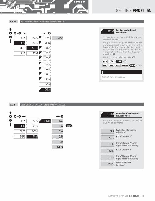
6.2.2e MATHEMATIC FUNCTIONS - MEASURING UNITS
6.2.3 SELECTION OF EVALUATION OF MIN/MAX VALUE
CHA.
SER.
OUT. M.FN.
C. B
INP. C. A
+
M. M.
M.FN.
C. B
C. C
C. F
C. E
C. D
C. A
I.MF.
FO.M
000
DE.M
LO.M
DE.M Setting projection of description
- 3 characters can be added to standard numerical formats
- setting is realised using modified ASCII code, where upper number defines position of the character, bottom line at the first position displays the charater and at the last two positions show the code of the character in interval 0…95.
- description is cancelled by code 000
- RTD T/C DEF = °C
- DC PM DU OHM DEF = none
Table of signs on page 86
!
DEFCHA.
SER.
OUT.
M. M.
C. B
INP. C. A
+
M.FN.
I.M.M. NO
C. A
F. A
C. B
F. B
M.FN.
I.M.M. Selection of evaluation of min/max value
- selection of value from which the min/max value will be calculated
NO Evaluation of min/max value is off
C. A From “Channel A”
F. A From “Channel A” after digital filters processing
C. B. From “Channel B”
F. B From “Channel B” after digital filters processing
M.FN. From “Mathematic functions”

64 | INSTRUCTIONS FOR USE OMX 102UNI
SETTING PROFI6.
6.3 SETTING „PROFI“ - OUTPUTS
6.3.1 SETTING OF EXCITATION VOLTAGE
6.3.2a SELECTION OF MODE OF DATA LOGGING INTO INSTRUMENT MEMORY
CHA.
SER.
OUT. LIM.
A. O.
DAT.
DIS.
INP.
+
MEM.
EXC.
In this menu it is possible to set parameters of the instrument output signals
EXC. Setting of excitation voltage
MEM. Setting data logging into memory
LIM. Setting type and parameters of limits
DAT. Setting type and parameters of data output
A. O. Setting type and parameters of analog output
DIS. Setting of backlight
EXC.
OUT.
SER.
CHA.
LIM.
INP.
A. O.
+
DAT.
DIS.
5V
12V
DEF24V
17V
LIM.
EXC. Setting of excitation voltage
5V 5 VDC, max. 2,5 W
12V 12 VDC, max. 2,5 W
17V 17 VDC, max. 2,5 W
24V 24 VDC, max. 2,5 W
REW.
OUT.
SER.
CHA. MEM.
LIM.
INP.
A. O.
+
DAT.
DIS.
NO
YES
DEF
STO.
PER.
TRG.
STA.
EXC.
REW. Selection of the mode of data logging
- selection of the mode in the event of full instrument memory
NO Rewriting values prohibited
YES Rewriting values permitted, the oldest get rewritten by
the latest
INSTRUCTIONS FOR USE OMX 102UNI | 65
6.SETTING PROFI
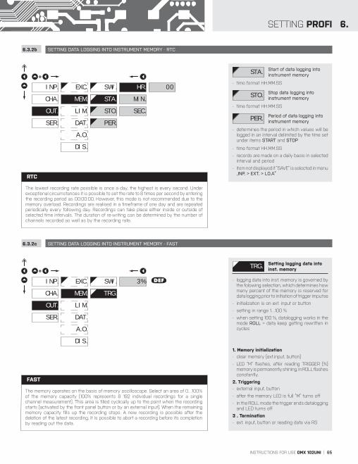
6.3.2b SETTING DATA LOGGING INTO INSTRUMENT MEMORY - RTC
6.3.2c SETTING DATA LOGGING INTO INSTRUMENT MEMORY - FAST
OUT.
SER.
CHA. MEM.
LIM.
INP.
A. O.
+
DAT.
DIS.
MIN.
STO.
PER.
SWI.
SEC.
00HR.
STA.
EXC.
STA. Start of data logging into instrument memory
- time format HH.MM.SS
STO. Stop data logging into instrument memory
- time format HH.MM.SS
PER. Period of data logging into instrument memory
- determines the period in which values will be logged in an interval delimited by the time set under items START and STOP
- time format HH.MM.SS
- records are made on a daily basis in selected interval and period
- item not displayed if “SAVE” is selected in menu „INP. > EXT. > LO.A”
EXC. DEF
OUT.
SER.
CHA. MEM.
LIM.
INP.
A. O.
+
DAT.
DIS.
SWI. 3%
TRG.
TRG. Setting logging data into inst. memory
- logging data into inst. memory is governed by the folowing selection, which determines how many percent of the memory is reserved for data logging prior to initiation of trigger imputse
- initialization is on ext. input or button
- setting in range 1…100 %
- when setting 100 %, datalogging works in the mode ROLL > data keep getting rewritten in cycles
1. Memory initialization
- clear memory (ext.input, button)
- LED “M” flashes, after reading TRIGGER (%) memory is permanently shining. In ROLL flashes constantly.
2. Triggering
- external input, button
- after the memory LED is full “M” turns off
- in the ROLL mode the trigger ends datalogging and LED turns off
3 . Termination
- ext. input, button or reading data via RS
The memory operates on the basis of memory oscilloscope. Select an area of 0…100% of the memory capacity (100% represents 8 192 individual recordings for a single channel measurement). This area is filled cyclically up to the point when the recording starts (activated by the front panel button or by an external input). When the remaining memory capacity fills up the recording stops. A new recording is possible after the deletion of the latest recording. It is possible to abort a recording before its completion by reading out the data.
FAST
The lowest recording rate possible is once a day, the highest is every second. Under exceptional circumstances it is possible to set the rate to 8 times per second by entering the recording period as 00:00:00. However, this mode is not recommended due to the memory overload. Recordings are realised in a timeframe of one day and are repeated periodically every following day. Recordings can take place either inside or outside of selected time intervals. The duration of re-writing can be determined by the number of channels recorded as well as by the recording rate.
RTC

66 | INSTRUCTIONS FOR USE OMX 102UNI
SETTING PROFI6.
Dose limit: MODE L. > “DOSE” axis x > “P” Period
z - delay “TIM. L.”
t
Switch-on relayTYPE > SWITCH-ON
LED signalization
Window limit: MODE L. > “FROM . .” axis x > “ON L.” switch on, “OFF L.” switch o
Switch-on relay
Switch-off relay
TYPE > SWITCH-ON
TYPE > SWITCH-OFF
LED signalization
LED signalization
axis x > “LIM. L.” limit, “H/2” hysteresi
Z > 0 - Switch-on relayTYPE > SWITCH-ON
Z < 0 - Switch-on relayTYPE > SWITCH-OFF
LED signalization
LED signalization
Z > 0 - Switch-off relayTYPE > SWITCH-ON
LED signalization
z
z
z
z z z
zz
Switch-off relayTYPE > SWITCH-OFF
LED signalization
z
TYPE > SWITCH-OFF
LED signalization
Z < 0 - Switch-off relay
DES
CR
IPTI
ON
OF
RELAY
FU
NC
TIO
N M
OD
E >
H
YS
TER
• F
RO
M -
TO • D
OS
ING

INSTRUCTIONS FOR USE OMX 102UNI | 67
6.SETTING PROFI
6.3.3a SELECTION OF INPUT FOR LIMITS EVALUATION
EXC.
OUT.
SER.
CHA.
LIM.
MEM.
INP.
A. O.
+
DAT.
DIS.
L. 2
L. 1 INP.
MOD.
TYP.
L. 1
H. 1
ON.1
OF.1
P. 1
T. 1
NO
M.FN.
F. A
C. A DEF
MAX
MIN
F. B
C. B
INP. Selection evaluation of limits
- selection of value from which the limit will be evaluated
NO Limit evaluation is off
C. A Limit evaluation from “Channel A”
F. A Limit evaluation from “Channel A” after digital
filters processing
C. B Limit evaluation from “Channel B”
F. B Limit evaluation from “Channel B” after digital
filters processing
M.FN. Limit evaluation from “Mathematic functions”
MIN. Limit evaluation from“Min. value”
MAX Limit evaluation from “Max. value”
Setting is identical for „L. 2”
!
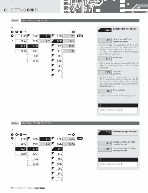
68 | INSTRUCTIONS FOR USE OMX 102UNI
SETTING PROFI6.
6.3.3b SELECTION OF TYPE OF LIMIT
6.3.3c SELECTION OF TYPE OF OUTPUT
EXC.
OUT.
SER.
CHA.
LIM.
MEM.
INP.
A. O.
+
DAT.
DIS.
L. 2
L. 1
MOD.
INP.
TYP.
L. 1
H. 1
ON.1
OF.1
P. 1
T. 1
HYS.
DOS.
F-T
DEF
ERR.
MOD. Selection the type of limit
HYS. Limit is in mode “Limit, hysteresis, delay”
- for this mode the parameters of “L. 1” are set, at which the limit will shall react, “H. 1”the hysteresis range around the limit (LIM ±1/2 HYS) and time “T. 1” determining the delay of relay switch-on
F-T Frame limit
- for this mode the parameters are set for interval “ON.1” the relay switch-on and “OF.1” the relay switch-off
DOS. Dose limit(periodic)
- for this mode the parameters are set for “P. 1” determining the limit value as well as its multiples at which the output is active and “T. 2” indicating the time during which is the output active
ERR. Error indication
- output is active when error message is on
Setting is identical for „L. 2”
!
EXC.
OUT.
SER.
CHA.
LIM.
MEM.
INP.
A. O.
+
DAT.
DIS.
L. 2
L. 1
TYP.
INP.
MOD.
L. 1
H. 1
ON.1
OF.1
P. 1
T. 1
CLO.
OPE.
DEF
TYP. Selection of type of output
CLO. Output switches on when condition is met
OPE. Output switches off when condition is met
Setting is identical for „L. 2”
!

INSTRUCTIONS FOR USE OMX 102UNI | 69
6.SETTING PROFI
6.3.3d SETTING VALUES FOR LIMITS EVALUATION
EXC.
OUT.
SER.
CHA.
LIM.
MEM.
INP.
A. O.
+
DAT.
DIS.
L. 2
L. 1
L. 1
INP.
MOD.
TYP.
H. 1
ON.1
OF.1
P. 1
T. 1
20 DEF
L. 1 Setting limit for switch-on
- for type “HYS.”
H. 1 Nastavení hystereze
- for type “HYS.”
- indicates the range around the limit (in both directions, LIM. ±1/2 HYS.)
ON.1 Setting the outset of the interval of limit switch-on
- for type “F-T”
OF.1 Setting the end of the interval of limit switch-on
- for type “F-T”
P. 1 Setting the period of limit switch-on
- for type “DOS.”
T. 1 Setting the time switch-on of the limit
- for type “HYS.” and “DOS.”
- setting within the range: ±0…99,9 s
- positive time > relay switches on after crossing the limit (L. 1) and the set time (T. 1)
- negative time > relay switches off after crossing the limit (L. 1) and the set negative time (T. 1)
Setting is identical for „L. 2”
!

70 | INSTRUCTIONS FOR USE OMX 102UNI
SETTING PROFI6.
6.3.4a SELECTION OF DATA OUTPUT BAUD RATE
6.3.4b SETTING INSTRUMENT ADDRESS
EXC.
+
CHA.
SER.
OUT. LIM.
A. O.
DAT.
DIS.
INP. BD 0.6
1.2
2.4
4.8
9.6
19.2
38.4
57.6
ADD.
DEF
115
230
A.MO.
A.PB.
GSD
PRO.
MEM.
BD Selection of data output baud rate
0.6 Rate - 600 Baud
1.2 Rate - 1 200 Baud
2.4 Rate - 2 400 Baud
4.8 Rate - 4 800 Baud
9.6 Rate - 9 600 Baud
19.2 Rate - 19 200 Baud
38.4 Rate - 38 400 Baud
57.6 Rate - 57 600 Baud
115 Rate - 115 200 Baud
230 Rate - 230 400 Baud
EXC.
+
CHA.
SER.
OUT. LIM.
A. O.
DAT.
DIS.
INP. 00BD
ADD.
A.MO.
A.PB.
GSD
PRO.
MEM.
ADD. Setting instrument address
- setting in range: 0…31
- DEF = 00
A.MO. Setting instrument address - MODBUS
- setting in range: 1…247
- DEF = 01
A.P.B. Setting instrument address- PROFIBUS
- setting in range: 1…127
- DEF = 19
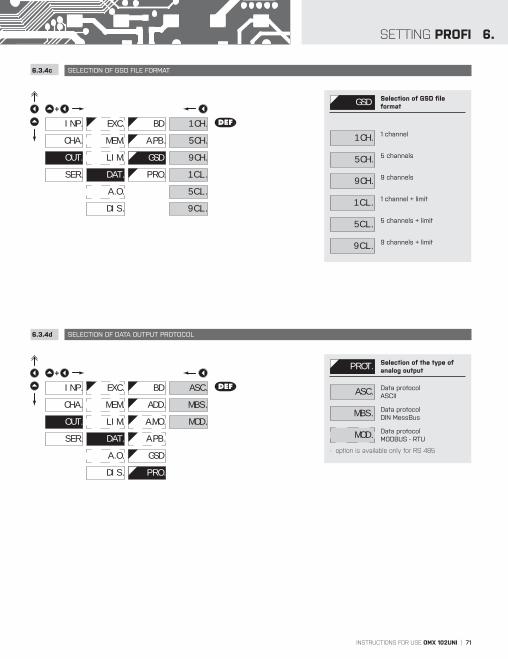
INSTRUCTIONS FOR USE OMX 102UNI | 71
6.SETTING PROFI
6.3.4c SELECTION OF GSD FILE FORMAT
6.3.4d SELECTION OF DATA OUTPUT PROTOCOL
EXC. DEF
+
CHA.
SER.
OUT. LIM.
A. O.
DAT.
DIS.
INP. 1CH.BD
GSD
A.PB.
PRO.
9C.L.
5C.L.
1C.L.
9CH.
5CH.MEM.
GSD Selection of GSD file format
1CH. 1 channel
5CH. 5 channels
9CH. 9 channels
1C.L. 1 channel + limit
5C.L. 5 channels + limit
9C.L. 9 channels + limit
EXC.
MEM.
+
CHA.
SER.
OUT. LIM.
A. O.
DAT.
DIS.
INP. ASC.BD
PRO.
A.MO.
A.PB.
GSD
ADD.
MOD.
M.BS.
DEF
PROT. Selection of the type of analog output
ASC. Data protocol ASCII
M.BS. Data protocol DIN MessBus
MOD. Data protocol MODBUS - RTU
- option is available only for RS 485

72 | INSTRUCTIONS FOR USE OMX 102UNI
SETTING PROFI6.
6.3.5a SELECTION OF INPUT FOR ANALOG OUTPUT
EXC.
MEM.
+
CHA.
SER.
OUT. LIM.
DAT.
A. O.
DIS.
INP. I.A.1
F.L.1
F.H.1
A.L.1
T.A.1
A. 1
A. 2
A.H.1
NO
M.FN.
F. A
C. A DEF
MAX
MIN
F. B
C. B
I.A.1 Selection evaluation analog output
- selection of value from which the analog output will be evaluated
NO AO evaluation is off
C. A AO evaluation from “Channel A”
F. A AO evaluation from “Channel A” after digital
filters processing
C. B AO evaluation from “Channel B”
F. B AO evaluation from “Channel B” after digital
filters processing
M.FN. AO evaluation from “Math. functions”
MIN AO evaluation from “Min. value”
MAX AO evaluation from“Max. value”
Setting is identical also for „A. 2””
!
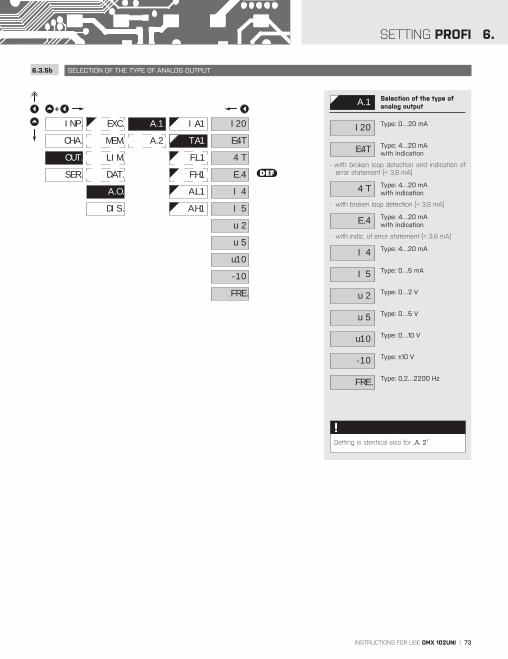
INSTRUCTIONS FOR USE OMX 102UNI | 73
6.SETTING PROFI
6.3.5b SELECTION OF THE TYPE OF ANALOG OUTPUT
EXC.
MEM.
+
CHA.
SER.
OUT. LIM.
DAT.
A. O.
DIS.
INP.
T.A.1
F.L.1
F.H.1
A.L.1
I.A.1A. 1
A. 2
A.H.1
I20
I 5
I 4
E. 4
u 2
u 5
DEF
u10
4 T
E.4T
-10
FRE.
A. 1 Selection of the type of analog output
I20 Type: 0…20 mA
E.4T Type: 4…20 mA with indication
- with broken loop detection and indication of error statement (< 3,6 mA)
4 T Type: 4…20 mAwith indication
- with broken loop detection (< 3,6 mA)
E. 4 Type: 4…20 mA with indication
- with indic. of error statement (< 3,6 mA)
I 4 Type: 4…20 mA
I 5 Type: 0…5 mA
u 2 Type: 0…2 V
u 5 Type: 0…5 V
u10 Type: 0…10 V
-10 Type: ±10 V
FRE. Type: 0,2…2200 Hz
Setting is identical also for „A. 2”
!

74 | INSTRUCTIONS FOR USE OMX 102UNI
SETTING PROFI6.
6.3.5c SETTING THE ANALOG OUTPUT RANGE
6.3.6 SELECTION OF DISPLAY BACKLIGHT
EXC.
MEM.
+
CHA.
SER.
OUT. LIM.
DAT.
A. O.
DIS.
INP.
F.L.1
T.A.1
F.H.1
A.L.1
I.A.1A. 1
A. 2
A.H.1
0
A. O. Setting the analog output range
- analog output is isolated and its value corresponds with displayed data. It is fully programmable, i.e. it allows to assign the AO limit points to two arbitrary points of the entire measuring range
F.L.1 Setting the beginning of the frequency range for
item „MIN“
- range of the setting: 0,2…2 200 Hz
- DEF = 0 (-40 - RTD, T/C)
F.H.1 Setting the end of the frequency range for item
„MAX“
- range of the setting: 0,2…2 200 Hz
- DEF = 100 (199 - RTD, T/C)
A.L.1 Assigning the display value to the beginning of the
AO range
- range of the setting: -99M…999M
- DEF = 0 (-40 - RTD, T/C)
A.H.1 Assigning the display value to the end of the AO range
- range of the setting: -99M…999M
- DEF = 100 (199 - RTD, T/C)
Setting is identical also for „A. 2”
!
EXC.
MEM.
+
CHA.
SER.
OUT. LIM.
DAT.
DIS.
A. O.
INP. B. L. NO
YES
TIM.
B. L. Backlight
NO Backlight is off
YES Backlight is on
TIM. Backlight is time limited
- after a key stroke the backlight is active for 60 s

INSTRUCTIONS FOR USE OMX 102UNI | 75
6.SETTING PROFI

76 | INSTRUCTIONS FOR USE OMX 102UNI
SETTING PROFI6.
6.4 SETTING “PROFI” - SERVICE
6.4.1 SELECTION OF TYPE OF PROGRAMMING MENU
+
CHA.
SER.
OUT.
MNU.
CAL.
INP.
N.PA.
RES.
ID.
LNG.
The instrument service functions are set in this menu
MNU. Selection of menu type LIGHT/PROFI
RES. Restore instrument manufacture setting and
calibration
CAL. Input range calibration for „DU“ version
LNG. Language version of instrument menu
C. M. Setting new access password
ID. Instrument identification
N.PA.
+
CHA.
OUT.
SER.
RES.
CAL.
MNU.
LNG.
INP.
PRO.
DEFLIG.
ID.
MNU. Selection of menu type - LIGHT/PROFI
- enables setting the menu complexity according to user needs and skills
LIG. Aktivní LIGHT menuActive LIGHT menu
- simple programming menu, contains only items necessary for configuration and instrument setting
- linear menu > items one after another
PRO. Active PROFI menu
- complete programming menu for expert users
- tree menu
Change of setting is valid upon next access into menu
!

INSTRUCTIONS FOR USE OMX 102UNI | 77
6.SETTING PROFI
6.4.2 RESTORATION OF MANUFACTURE SETTING
JOBS PERFORMEDRESTORE
CALIBRATION SETTING
cancels USER menu rights deletes table of items order in USER - LIGHT menu adds items from manufcture to LIGHT menu deletes data stored in FLASH cancels or linearization tables clears tare restore manufacture calibration restore manufacture setting
N.PA.
+
CHA.
OUT.
SER.
MNU.
CAL.
RES.
LNG.
INP.
ID.
YESRE.C.
SET.
SAV.
RES. Restoration of manufacture setting
- in the event of error setting or calibration, manufacture setting may be restored
RE.C. Restoration of manufacture calibration of the instrument
- prior executing the changes you will be asked to confirm you selection „YES“
SET. Restoration of instrument manufacture setting
FIR. Restoration of instrument manufacture setting
- generating the manufacture setting for currently selected type of instrument (items marked DEF)
USR. Restoration of instrument user setting
- generating the instrument user setting, i.e. setting stored under SER./RES./SAV.
SAV. Save instrument user setting
- storing the user setting allows the operator to restore it in future if needed
After restoration the instrument switches off for couple seconds
!N.PA.
+
CHA.
OUT.
SER.
MNU.
CAL.
RES.
LNG.
INP.
ID.
FIR.
SET.
RE.C.
SAV.
USR.

78 | INSTRUCTIONS FOR USE OMX 102UNI
SETTING PROFI6.
6.4.3 CALIBRATION - INPUT RANGE DU
6.4.4 SELECTION OF INSTRUMENT MENU LANGUAGE VERSION
6.4.5 SETTING NEW ACCESS PASSWORD
N.PA.
+
CHA.
OUT.
SER.
MNU.
RES.
CAL.
LNG.
INP.
ID.
C.L.1CH.1
CH.2 C.H.1
YES
CH.1 Kalibrace vstupního rozsahu
- when “C.L.1” is displayed, move the potentiometer traveller to the required minimum position and confirm by „Enter“, calibration is confirmed by “YES“
- when “C.H.1” is displayed, move the potentiometer traveller to required maximum position and confirm by „Enter“, calibration is confirmed by “YES“
This setting is identical also for „CH.2”
!
N.PA.
+
CHA.
OUT.
SER.
MNU.
RES.
LNG.
CAL.
INP.
ID.
CZ
ENG. DEF
LNG. Selection of instrument menu language version
CZ Instrument menu is in Czech
ENG. Instrument menu is in English
LNG.
+
CHA.
OUT.
SER.
MNU.
RES.
N.PA.
CAL.
INP.
ID.
000
P.PR.
P.LI.
N.PA. Setting new password for access to LIGHT and PROFI
menu
- this option allows to change the numeric code, which blocks the access into LIGHT and PROFI menu.
- numerci code range: 0…999
- universal passwords in the event of loss: LIGHT Menu > „177“ PROFI Menu > „915““

INSTRUCTIONS FOR USE OMX 102UNI | 79
6.SETTING PROFI
6.4.6 INSTRUMENT IDENTIFICATION
LNG.
+
CHA.
OUT.
SER.
MNU.
RES.
ID.
CAL.
INP.
N.PA.
61-008OMX 102UNI PM
ID. Projection of instrument SW version
- display shows type identification of the instrument, SW number, SW version andcurrent input setting (Mode)
- if the SW version reads a letter on first position, it is a customer SW
IDEN
T.
Pos. Description
1. type of instrument
2. SW: number - version
3. the input type

80 | INSTRUCTIONS FOR USE OMX 102UNI
SETTING USER7.
SETTING USERFor user operationMenu items are set by the user (Profi/Light) as per requestAccess is not password protected Optional menu structure either tree (PROFI) or linear (LIGHT)
7.0 SETTING ITEMS INTO “USER” MENU
• USER menu is designed for users who need to change only several items of the setting without the option to change the
primary instrument setting (e.g. repeated change of limit setting)
• there are no items from manufacture permitted in USER menu
• on items indicated by inverse triangle LIM 1
• setting may be performed in LIGHT or PROFI menu, with the USER menu then overtaking the given menu structure
Setting
NO item will not be displayed in USER menu
YES item will be displayed in USER menu with editing option
SHO. item will be solely displayed in USER menu
--- NO YES SHO. ---
return to item
legend is flashing - current setting is displayed
> 2s

INSTRUCTIONS FOR USE OMX 102UNI | 81
7.SETTING USER
Setting sequence of items in “USER” menu
In compiling USER menu from active LIGHT menu the items (max. 10) may be assigned a sequence, in which they will be projected in the menu
Example of ranking the order of menu items in the “USER” menu
In this example we want to have a direct access to menu items Limit 1 and Limit 2 (example show is for the Light menu, but can equaly be used in the Profi menu).
The result of this setting is that when the button is pressed, the display will read „L.1“. By pressing button you confirm
your selection and then you can set the desired limit value, or by pressing the button you can go to setting of „L.2“ where
you can proceed identically as with Limit one.
You can exit the setting by pressing the button by which you store the latest setting and pressing the button will take
you back to the measuring mode
--- 0
setting projection sequence
142 PAS. 0
Access password
MINTYP. MOD. FOR. L.1MAX +
NO SHO.YES L.1 L.2 +
Selecting an item from the main menu
+ 0 L.1
142NO SHO.YES L.2 + 0 L.21
Selecting an item from the main menu
Item position in the menu
Item position in the menu
> 2s
> 2s

82 | INSTRUCTIONS FOR USE OMX 102UNI
METHOD OF MEASURING THE CJC8.
Instrument with input for temperature measurement with thermocouple allows to set two types of measurement of cold junction.
WITH REFERENCE THERMOCOUPLE
– a reference thermocouple may be located in the same place as the measuring instrument or in place with stable temperature/ compensation box
– when measuring with reference thermocouple set CO.1 in the instrument menu to IN.2 or EX.2
– when using a thermostat (a compensation box or environment with constant temperature) set in the instrument menu C.J.1 its temperature (applies for setting CO.1 to EX.2)
– if the reference thermocouple is located in the same environment as the measuring instrument then set in the instrument menu CO.1 to IN.2. Based on this selection the measurement of the ambient temperature is performed by a sensor located in the instrument terminal board
WITHOUT REFERENCE THERMOCOUPLE
– inaccuracy originating from the creation of dissimilar thermocouples on the transition point terminal/conductor of the thermocouple is not compensated for in the instrument
– when measuring without reference thermocouple set CO.1 in the instrument menu to IN.1 or EX.1
– when measuring temperature without reference thermocouple the error in measured data may be as much as 10°C (applies for setting CO.1 to EX.1)
J+
V
J2
Reference thermocouple
Measuring thermocouple+
+ ---
OM xxx T/C
1

INSTRUCTIONS FOR USE OMX 102UNI | 83
9.ERROR STATEMENTS
ERROR CAUSE ELIMINATION
E.D._ Number is too small (large negative) to be displayed change DP setting, channel constant setting
E.D._ Number is too large to be displayed change DP setting, channel constant setting
E.T._ Number is outside the table rangeincrease table values, change input setting (channel constant setting)
E.T._ Number is outside the table range
increase table values, change input setting(channel constant setting)
E.I._Input quantity is smaller than permitted input quan-tity range change input signal value or input (range) setting
E.I._ Input quantity is larger than permitted input quantity
range change input signal value or input (range) setting
E.HW. A part of the instrument does not work properly send the instrument for repair
E.EE Data in EEPROM corrupted perform restoration of manufacture setting, upon repeated error statement send instrument for repair
E.DT. Data in EEPROM outside the range perform restoration of manufacture setting, upon repeated error statement send instrument for repair
E.CL. Memory was empty (presetting carried out) upon repeated error statement send instrument for repair, possible failure in calibration
E.Ou . Analogue input/output current loop disconnected check wire connection

84 | INSTRUCTIONS FOR USE OMX 102UNI
DATA PROTOCOL10.
The instruments communicate via serial line RS232 or RS485. For communication they use the ASCII protocol. Communication runs in the following format:
ASCII: 8 bit, no parity, one stop bitDIN MessBus: 7 bit, even parity, one stop bit
The transfer rate is adjustable in the instrument menu. The instrument address is set in the instrument menu in the range of 0 ÷ 31. The manufacture setting always presets the ASCII protocol, rate of 9600 Baud, address 00. The type of line used - RS232 / RS485 - is determined by an output board automatically identified by the instrument.The commands are described in specifications you can find at www.orbit.merret.eu or SW OM Link.
DETAILED DESCRIPTION OF COMMUNICATION VIA SERIAL LINE
EVENT TYPE PROTOCOL TRANSMITTED DATA
Data solicitation (PC)
23
2 ASCII # A A <CR>
MessBus No - data is transmitted permanently
485 ASCII # A A <CR>
MessBus <SADR> <ENQ>
Data transmission (instrument)
23
2 ASCII > D (D) (D) (D) (D) (D) (D) (D) (D) (D) <CR>
MessBus <STX> D (D) (D) (D) (D) (D) (D) (D) (D) (D) <ETX> <BCC>
485 ASCII > D (D) (D) (D) (D) (D) (D) (D) (D) (D) <CR>
MessBus <STX> D (D) (D) (D) (D) (D) (D) (D) (D) (D) <ETX> <BCC>
Confirmation of data acceptannce(PC) - OK
485
MessBus
<DLE> 1
Confirmation of data acceptance(PC) - Bad
<NAK>
Sending address (PC) prior command <EADR> <ENQ>
Confirmation of address (instrument) <SADR> <ENQ>
Command transmission (PC)
23
2 ASCII # A A N P (D) (D) (D) (D) (D) (D) (D) <CR>
MessBus <STX> $ N P (D) (D) (D) (D) (D) (D) (D) <ETX> <BCC>
485 ASCII # A A N P (D) (D) (D) (D) (D) (D) (D) <CR>
MessBus <STX> $ N P (D) (D) (D) (D) (D) (D) (D) <ETX> <BCC>
Command confirmation (instrument)
23
2 AS
CII OK ! A A <CR>
Bad ? A A <CR>
Messbus No - data is transmitted permanently
485 A
SC
II OK ! A A <CR>
Bad ? A A <CR>
Mes
s-B
us
OK <DLE> 1
Bad <NAK>
Instrument identification # A A 1 Y <CR>
HW identification # A A 1 Z <CR>
One-time transmission # A A 7 X <CR>
Repeated transmission # A A 8 X <CR>

INSTRUCTIONS FOR USE OMX 102UNI | 85
10.DATA PROTOCOL
LEGEND
SING RANGE DESCRIPTION
# 35 23H
Command beginning
A A 0…31Two characters of instrument address(sent in ASCII - tens and units, e.g. “01“, “99“ universal
<CR> 13 0DH
Carriage return
<SP> 32 20H
Space
N, P Number and command - command code
D Data - usually characters “0“…“9“, “-“, “.“; (D) - dp. and (-) may prolong data
R 30H…3F
HRelay and tare status
! 33 21H
Positive confirmation of command (ok)
? 63 3FH
Negative confirmation of command (point)
> 62 3EH
Beginning of transmitted data
<STX> 2 02H
Beginning of text
<ETX> 3 03H
End of text
<SADR> adresa +60H
Prompt to send from address
<EADR> adresa +40H
Prompt to accept command at address
<ENQ> 5 05H
Terminate address
<DLE>1 16 49 10H 31
HConfirm correct statement
<NAK> 21 15H
Confirm error statement
<BCC> Check sum -XOR
RELAY, TARE
SIGN RELAY 1 RELAY 2 TARE CHANGE
P 0 0 0 0
Q 1 0 0 0
R 0 1 0 0
S 1 1 0 0
T 0 0 1 0
U 1 0 1 0
V 0 1 1 0
W 1 1 1 0
Relay status is generated by command #AA6X <CR>. The instrument immediately returns the value in the format >HH <CR>, where HH is value in HEX format and range 00
H…FF
H. The lowest bit stands for „Relay
1“, the highest for „Relay 2“

86 | INSTRUCTIONS FOR USE OMX 102UNI
TABLE OF SIGNS11.
The instrument allows to add two descriptive characters to the classic numeric formats (at the expense of the number of displayed places). The setting is performed by means of a shifted ASCII code. Upon modification the first two places display the entered characters and the last two places the code of the relevant symbol from 0 to 95. Numeric value of given character equals the sum of the numbers on both axes of the table.Description is cancelled by entering characters with code 00

INSTRUCTIONS FOR USE OMX 102UNI | 87

88 | INSTRUCTIONS FOR USE OMX 102UNI
TECHNICAL DATA12.
INPUT - OMX 102UNI
No. of inputs: up to 2 DCRange: ±90 mA < 200 mV Input 5 ±180 mA < 200 mV Input 5 ±30 mV > 10 MΩ Input 3 ±60 mV > 10 MΩ Input 3 ±1000 mV > 10 MΩ Input 3 ±20 V 1,25 MΩ Input 1
±40 V 1,25 MΩ Input 1 ±80 V 1,25 MΩ Input 1
PMRange: ±5 mA < 200 mV Input 5 ±20 mA < 200 mV Input 5 4...20 mA < 200 mV Input 5 ±2 V > 10 MΩ Input 1 ±5 V 1,25 MΩ Input 1 ±10 V 1,25 MΩ Input 1
OHMRange: 0…100 Ω 0…300 Ω 0…1,5 kΩ 0…3,0 kΩ
0…24,0 kΩ 0…30,0 kΩ
Connection: 2, 3 or 4 -wire
RTD
EU • Pt xxxx -50°…450°CUS • Pt 100 -50°…450°CRU • Pt 50 -200°…1 100°CRU • Pt 100 -200°…450°CCu 100/4 280 -200°…200°CCu 100/4 260 -50°…200°CNi xxxx -50°..250°C
Typ Pt: EU > 100/500/1 000 Ω, with 3 850 ppm/°C US > 100 Ω, with 3 920 ppm/°C RU > 50/100 Ω with 3 910 ppm/°CTyp Ni: Ni 1 000/ Ni 10 000 with 5 000/6 180 ppm/°CTyp Cu: Cu 50/Cu 100 with 4 260/4 280 ppm/°C
Connection: 2, 3 or 4 -wire
T/CType: J (Fe-CuNi) -100°…900°C K (NiCr-Ni) -100°…1 300°C T (Cu-CuNi) -200°…400°C E (NiCr-CuNi) -100°…800°C B (PtRh30-PtRh6) 700°…1 820°C S (PtRh10-Pt) 100°…1 760°C R (Pt13Rh-Pt) 100°…1 760°C N (Omegalloy) -0°…1 300°C L (Fe-CuNi) -100°…900°C
Voltage of lin. pot. 2,5 VDC/6 mA DU min. potentiometer resistance is 500 Ω
INPUT - OMX 102DC
No. of inputs: 1Range: ±1 A < 200 mV Input 5 ±5 A < 200 mV Input 5 ±25 V 1,25 MΩ Input 1
±50 V 1,25 MΩ Input 1 ±100 V 1,25 MΩ Input 1 ±200 V 1,25 MΩ Input 1 ±400 V 1,25 MΩ Input 1
PROJECTION
Display: LCD with backlight, 2x 3 characters + 2x description (3 characters)Projection -99M…999MDecimal point: adjustable - in menu
INSTRUMENT ACCURACY
TK: 50 ppm/°CPřesnost: ±0,15 % of range + 1 digit
±0,3 % of range + 1 digit T/CAccuracy of coldjunction measur.: ±1,5°CRate: 0,5…160 measurements/sPřetížitelnost: 2x; 10x (t < 100 ms) not for > 200 V and 5 A,Linearisation: by linear interpolation in 50 points - solely via OM Link Digital filters: Averaging, Floating average, Exponential filter,
Rounding Comp. of conduct: max. 40 Ω/100 Ω RTDComp. of cold junc.: adjustable T/C 0°...99°C or automaticFunctions: Tare - display resetting Hold - stop measuring (at contact) Lock - control key locking MM - min/max value Mathematic functionsOM Link: company communication interface for setting,
operation and update of instrument SWWatch-dog: reset after 400 msCalibration: at 25°C and 40 % of r.h.

INSTRUCTIONS FOR USE OMX 102UNI | 89
12.TECHNICAL DATA
COMPARATOR
Type: digital, adjustable in menu, response time < 50 ms
Mode: Hyster, F-T, Dosing, ErrorLimits: 999, resp -99M…999MHysteresis: 0…999, resp. 999 kDelay: 0…99,9 sVýstupy: 2x relays with switch-on contact (Form A)Relay: 1/8 HP 277 VAC, 1/10 HP 125 V, Pilot Duty D300
DATA OUTPUTS
Protocols: ASCII, DIN MessBus, MODBUS, PROBUSData format: 8 bit + no parity + 1 stop bit (ASCII) 7 bit + even parity + 1 stop bit (MessBus)Rate: 600…230 400 Baud 9 600 Baud…12 Mbaud (PROFIBUS)
1 Mbaud (CAN)
RS 232: isolated, two-way communicationRS 485: isolated, two-way communication, addressing (max. 31 instruments)PROFIBUS Data protocol SIEMENSEthernet: 10/100BaseT, secure communication, POP3, ftp,
httpUSB not-isolated, two-way communication
ANALOG OUTPUTS
Type: isolated, dual, programmable with 16 bits D/A convertor, analogoutput corresponds with displayed data, type and range are adjustable
Non-linearity: 0,1 % of rangeTC: 15 ppm/°CRate: response to change of value < 1 msVoltage: 0…2 V/5 V/10 V/±10 VCurernt: 0…5/20 mA/4…20 mA - compensation of conduct to 500 Ω/12 V Freqency: isolated, programmable, open collector with the option of external supply (max. 40 V) vie intervnal resistance (5k6), 0,2…2200 Hz
MEASURED DATA RECORD
Type RTC: time-controlled logging of measured data into instrument memory, allows to log up to 250 000 values
Type FAST: fast data logging into instrument memory, allows to log up to 8 000 values at a rate of 40 records/s
Transmission: via USB or data output RS 232/485 or via OM Link
EXCITATION
Adjustbale 5/12/17/24 VDC, max. 2,5 W, isolated
POWER SUPPLY
Options: 10…30 V AC/DC, max. 13,5 VA, PF ≥ 0,4, ISTP
< 40 A/1 ms, isolated - fuse inside (T 4000 mA)
80…250 V AC/DC, max. 13,5 VA, PF ≥ 0,4, ISTP
< 40 A/1 ms, isolated - fuse inside (T 630 mA)
MECHANIC PROPERTIES
Material: PA 66, incombustible UL 94 V-I, blueDimensions: 113 x 98 x 35 mmInstallation: to DIN rail, width 35 mm
OPERATING CONDITIONS
Connection: connector terminal board, conductor cross-section <1,5 mm2 /<2,5 mm2
Stabilisation period: within 15 minutes after switch-onWorking temp.: -20°…60°C Storage temp.: -20°…85°CCover: IP20Construction: safety class IOvervoltage cat.: EN 61010-1, A2Dielectric strength: 4 kVAC after 1 min between supply and input
4 kVAC after 1 min between supply and data/analog output 4 kVAC after 1 min between supply and relays 3,75 kVAC after 1 min between input and data/analog output 3,75 kVAC after 1 min between inputs
Insulation resist.: for pollution degree II, measurement cat. III supply, input, output > 600 V (ZI), 300 V (DI)EMC: EN 61326-1Seismic resistance: IEC 980: 1993, par. 6
* values apply for resistance load PI - Primary insulation, DI - Double insulation
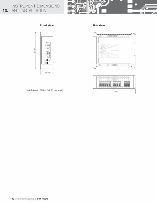
90 | INSTRUCTIONS FOR USE OMX 102UNI
INSTRUMENT DIMENSIONS AND INSTALLATION13.
INPUT
OUTPUT
1 2
97 m
m
35 mm
113 mm
Side viewFront view
Installation to DIN rail of 35 mm width

INSTRUCTIONS FOR USE OMX 102UNI | 91
14.CERTIFICATE
OF GUARANTEE
Product OMX 102UNI DC
Type . . . . . . . . . . . . . . . . . . . .
Manufacturing No. . . . . . . . . . . . . . . . . . . . .
Date of sale . . . . . . . . . . . . . . . . . . . .
A guarantee period of 60 months from the date of sale to the user applies to this instrument.Defects occuring during this period due to manufacture error or due to material faults shall be eliminated free of charge.
For quality, function and construction of the instrument the guarantee shall apply provided that the instrument was connected and used in compliance with the instructions for use.
The guarantee shall not apply to defects caused by:
- mechanic damage - transportation - intervention of unqualified person incl. the user - unavoidable event - other unprofessional interventions
The manufacturer performs guarantee and post.guarantee repairs unless provided for otherwise.
Stamp, signature
GUARANTEE
Y E A R S
to the user applies to this instrument.or or due to material faults shall be elimina
shall apply provided that the in
of 60 months from thuring this period due
and constructioance with the i
l not apply
echanicanspotervention navoidable even
nprofessional intervention
antee and post.guarantee repairs
by:
herwise.

92 | INSTRUCTIONS FOR USE OMX 102UNI
ES DECLARATIONOF CONFORMITY
TECHDOK - OMX 102 - 2014 - 1v0 - en
Company: ORBIT MERRET, spol. s r.o. Klánova 81/141, 142 00 Prague 4, Czech Republic, IDNo.: 00551309
Manufactured: ORBIT MERRET, spol. s r.o. Vodňanská 675/30, 198 00 Prague 9, Czech Republic
declares at its explicit responsibility that the product presented hereunder meets all technical requirements, is safe for use when utilised under the terms and conditions determined by ORBIT MERRET, spol.s r.o. and that our company has taken all measures to ensure conformity of all products of the types referred-to hereunder, which are being brought out to the market, with technical documentation and requirements of the appurtenant Czech statutory orders.
Product: Programmable panel instrument Type OMX 102 Version: DC, UNI, PWR, UQC, T
Thas been designed and manufactured in line with requirements of:
Statutory order no. 17/2003 Coll., on low-voltage electrical equipment (directive no. 73/23/EHS)Statutory order no. 616/2006 Coll., on electromagnetic compatibility (directive no. 2004/108/EHS)
The product qualities are in conformity with harmonized standard:
El. safety: EN 61010-1EMC: EN 61326-1 Electronic measuring, control and laboratory devices – Requirements for EMC “Industrial use” EN 50131-1, chap. 14 and chap. 15, EN 50130-4, chap. 7, EN 50130-4, chap. 8, (EN 61000-4-11, ed. 2), EN 50130-4, chap. 9 (EN 61000-4-2), EN 50130-4, chap. 10, (EN 61000-4-3, ed. 2), EN 50130-4, chap. 11 (EN 61000-4-6), EN 50130-4, chap. 12, (EN 61000-4-4, ed. 2), EN 50130-4, chap. 13 (EN 61000-4-5), EN 61000-4-8, EN 61000-4-9, EN 61000-6-1, EN 61000-6-2, EN 55022, chap. 5 and chap. 6
Seismic resistance: IEC 980: 1993, par. 6
The product is furnished with CE label issued in 2014
As documentation serve the protocoles of authorized and accredited organizations:
EMC MO CR, Testing institute of technical devices, protocol no. 80/6-46/2006 of 15/01/2014 MO CR, Testing institute of technical devices, protocol no. EMI.80/6-333/2006 of 15/01/2014
Seismic resistance VOP-026 Stemberk, protocol no.: 6430-16/2007 of 07/02/2007 03/03/2014
Place and date of issue: Prague, 5. Februar 2014 Miroslav Hackl v.r. Company representative
Assessment of conformity pursuant to §22 of Act no. 22/1997 Coll. and changes as amended by Act no.71/2000 Coll. and 205/2002 Coll