
OmniSwitch Feature Guidelines AOS Release 6.6.2 · 2015-07-29 · Maximum number of rings supported...
73
Part No. 013002-01, Rev. A March 2011 OmniSwitch Feature Guidelines AOS Release 6.6.2.R01 OmniSwitch 6250Metro Model Alcatel-Lucent EDS 26801 West Agoura Road, Calabasas, CA 91301 (818) 880-3500 www.alcatel-lucent.com Copyright © 1995-2011 Alcatel-Lucent ALL RIGHTS RESERVED WORLDWIDE
Transcript of OmniSwitch Feature Guidelines AOS Release 6.6.2 · 2015-07-29 · Maximum number of rings supported...

Part No. 013002-01, Rev. A March 2011
OmniSwitch Feature Guidelines AOS Release 6.6.2.R01 OmniSwitch 6250Metro Model
Alcatel-Lucent EDS 26801 West Agoura Road, Calabasas, CA 91301
(818) 880-3500 www.alcatel-lucent.com
Copyright © 1995-2011 Alcatel-Lucent ALL RIGHTS RESERVED WORLDWIDE
OmniSwitch Feature Guidelines Part No. 013002-01, Rev. A AOS Release 6.6.2.R01 (OmniSwitch 6250-Metro) March 2011
Table of Contents 1. About This Guide ............................................................................................................................................ 3 2. New Feature Guidelines ................................................................................................................................. 4
2.1. Ethernet Ring Protection ............................................................................................................................ 5 2.2. Egress Policy Support ................................................................................................................................ 6 2.3. 802.1ad CFI/DEI Bit Support .................................................................................................................... 8 2.4. QoS Egress Port/Queue and Statistics Enhancements ............................................................................. 11 2.5. Policy Condition Enhancements .............................................................................................................. 14 2.6. Map Several Inner DSCP/ToS Values to Same Outer 802.1p ................................................................. 15 2.7. VLAN Stacking –Tunneling L2 Protocols .............................................................................................. 17 2.8. Advanced (Hardware) Ethernet Loopback .............................................................................................. 21 2.9. CPE Test Head ......................................................................................................................................... 27 2.10. Ethernet OAM 802.1ag Version 8 and ITU Y1731 ............................................................................... 30 2.11. SAA for ETHOAM ................................................................................................................................ 45 2.12. IP SAA (IP-Ping) ................................................................................................................................... 49 2.13. L2 SAA (MAC-Ping)............................................................................................................................. 52 2.14. DHCP Client .......................................................................................................................................... 56 2.15. Out-of-the-Box Auto-Configuration ...................................................................................................... 59 2.16. Dying Gasp ............................................................................................................................................ 67
3. Existing Feature Guidelines ......................................................................................................................... 69 3.1. Spanning Tree .......................................................................................................................................... 70 3.2. General L3 Routing ................................................................................................................................. 73
Alcatel-Lucent Page 2 of 73
OmniSwitch Feature Guidelines Part No. 013002-01, Rev. A AOS Release 6.6.2.R01 (OmniSwitch 6250-Metro) March 2011
1. About This Guide The OmniSwitch Feature Guidelines document provides recommendations and guidelines for release 6.6.2.R01 of the OmniSwitch 6250 Metro Model.
Reading the 6.6.2.R01 Release Notes prior to reading this guide is highly recommended.
What is in this Guide? This Section … Contains …
New Feature Guidelines Information about new features and enhancements introduced in the 6.6.2.R01 release. This includes a brief description, platforms supported, guidelines, sample configurations, and references to other related documentation.
Existing Feature Guidelines Information about existing features (introduced in a previous release). These features are included in this guide to provide additional information about general switch guidelines and functionality.
Alcatel-Lucent Page 3 of 73
OmniSwitch Feature Guidelines Part No. 013002-01, Rev. A AOS Release 6.6.2.R01 (OmniSwitch 6250-Metro) March 2011
2. New Feature Guidelines This section contains guidelines for the following new and enhanced features that were introduced in the OmniSwitch AOS Release 6.6.2.R01:
Bridging
• Ethernet Ring Protection
QoS
• Egress Policy Support • 802.1ad DEI/CFI Bit Support • Egress Port/Queue QoS and Statistics
Enhancements • Policy Condition Enhancements • Map Several Inner DSCP/ToS Values to Same
Outer 802.1p
Ethernet Access (Metro)
• VLAN Stacking –Tunneling L2 Protocols • Advanced Ethernet Loopback • CPE Test Head • Ethernet OAM 802.1ag Version 8 and ITU
Y1731 • SAA for ETHOAM • IP SAA (IP-Ping) • L2 SAA (MAC-Ping)
Management
• DHCP Client • Out-of-the-Box Auto-Configuration • Dying Gasp
Alcatel-Lucent Page 4 of 73
OmniSwitch Feature Guidelines Part No. 013002-01, Rev. A AOS Release 6.6.2.R01 (OmniSwitch 6250-Metro) March 2011
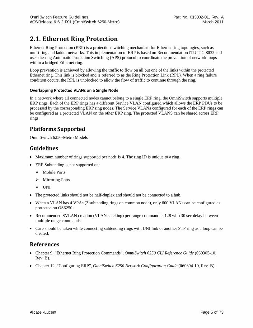
2.1. Ethernet Ring Protection Ethernet Ring Protection (ERP) is a protection switching mechanism for Ethernet ring topologies, such as multi-ring and ladder networks. This implementation of ERP is based on Recommendation ITU-T G.8032 and uses the ring Automatic Protection Switching (APS) protocol to coordinate the prevention of network loops within a bridged Ethernet ring.
Loop prevention is achieved by allowing the traffic to flow on all but one of the links within the protected Ethernet ring. This link is blocked and is referred to as the Ring Protection Link (RPL). When a ring failure condition occurs, the RPL is unblocked to allow the flow of traffic to continue through the ring.
Overlapping Protected VLANs on a Single Node
In a network where all connected nodes cannot belong to a single ERP ring, the OmniSwitch supports multiple ERP rings. Each of the ERP rings has a different Service VLAN configured which allows the ERP PDUs to be processed by the corresponding ERP ring nodes. The Service VLANs configured for each of the ERP rings can be configured as a protected VLAN on the other ERP ring. The protected VLANS can be shared across ERP rings.
Platforms Supported OmniSwitch 6250-Metro Models
Guidelines • Maximum number of rings supported per node is 4. The ring ID is unique to a ring.
• ERP Subtending is not supported on:
Mobile Ports
Mirroring Ports
UNI
• The protected links should not be half-duplex and should not be connected to a hub.
• When a VLAN has 4 VPAs (2 subtending rings on common node), only 600 VLANs can be configured as protected on OS6250.
• Recommended SVLAN creation (VLAN stacking) per range command is 128 with 30 sec delay between multiple range commands.
• Care should be taken while connecting subtending rings with UNI link or another STP ring as a loop can be created.
References • Chapter 9, “Ethernet Ring Protection Commands”, OmniSwitch 6250 CLI Reference Guide (060305-10,
Rev. B).
• Chapter 12, “Configuring ERP”, OmniSwitch 6250 Network Configuration Guide (060304-10, Rev. B).
Alcatel-Lucent Page 5 of 73
OmniSwitch Feature Guidelines Part No. 013002-01, Rev. A AOS Release 6.6.2.R01 (OmniSwitch 6250-Metro) March 2011
2.2. Egress Policy Support OmniSwitch egress policy rules allow administrators to enforce traffic controls on the egress queues as a “last resort” action. By default, QoS policy rules are applied to traffic ingressing the port. The QoS Policy List feature includes an “egress” policy list option to create a list of rules that are applied to traffic egressing a destination port(s). If a policy rule is not associated with an egress policy list, the rule will only apply to ingress traffic.
Platforms Supported OmniSwitch 6250-Metro Models
Guidelines • Refer to the 6.6.2R01 OmniSwitch 6250 Network Configuration Guide for more information about creating
egress policy lists and supported policy conditions and actions for egress rules.
• The maximum number of egress policy rules supported is 512.
• VLAN translate mode and egress policy rule configuration are mutually exclusive.
• There is no support for destination/egress Linkagg for Egress policy. This behavior is similar to Ingress policy. The workaround is to create a port group of all the ports that are part of a Linkagg and apply a single rule.
• Logging policy rules is not supported.
Egress Policy Condition Guidelines
• Only two Destination Port Groups are supported per egress policy condition.
• IPv6 conditions are not supported for egress policy.
• Source port and source port group conditions are not supported.
• srTCM/trTCM metering is not supported for egress policy condition.
• Inner VLAN and Inner 802.1p conditions are not supported.
Egress Policy Action Guidelines
• There is no action to assign internal priority/CoS, hence it is not supported.
• Policy based routing, redirect to port/LinkAgg and Policy based mirroring actions are not supported.
Alcatel-Lucent Page 6 of 73

OmniSwitch Feature Guidelines Part No. 013002-01, Rev. A AOS Release 6.6.2.R01 (OmniSwitch 6250-Metro) March 2011
Configuration Examples The following policy rule is created as an ingress rule and is automatically assigned to the default policy list:
policy vlan group vlan_group3 3000 3100-3105 policy condition cond1 source mac 00:11:22:33:44:55 source vlan 100 policy condition cond2 source ip 1.2.3.4 policy condition cond3 source port 1/1 destination port 2/23 policy condition cond4 source vlan group vlan_group3 policy action act1 disposition drop policy action act2 maximum bandwidth 1.00M policy action act3 802.1p 5 policy rule rule1 condition cond1 action act1 qos apply
The policy rules in the following example are assigned to the egress policy list and are not assigned to the default policy list:
policy condition c1 destination port 4/1 inner source vlan 10 policy action a1 maximum bandwidth 512k policy rule r1 condition c1 action a1 no default-list policy port group g2 7/5 7/6 policy condition c2 destination port group g2 inner source vlan 20 policy action a2 maximum bandwidth 50.00M policy rule r2 condition c2 action a2 no default-list policy list egress-list type egress rules r1 r2 qos apply
References • Chapter 21, “QoS Commands”, and Chapter 22, “QoS Policy Commands”, OmniSwitch 6250 CLI
Reference Guide (060305-10, Rev. B).
• Chapter 34, “Configuring QoS”, OmniSwitch 6250 Network Configuration Guide (060304-10, Rev. B).
Alcatel-Lucent Page 7 of 73
OmniSwitch Feature Guidelines Part No. 013002-01, Rev. A AOS Release 6.6.2.R01 (OmniSwitch 6250-Metro) March 2011
2.3. 802.1ad CFI/DEI Bit Support When the sr/trTCM ingress rate limiter is used, frames that are non-conforming to the SLA (yellow) might still be delivered to the egress port when the port is not congested. In addition, there is no way for the upstream switch to know that some of the received frames were marked yellow by the downstream switch. By enabling CFI/DEI bit marking on these frames, a color-aware upstream switch would be able to treat these frames differently and drop them first when the network is congested.
Platforms Supported OmniSwitch 6250-Metro Models
Guidelines • By default, CFI/DEI bit marking (egress) is disabled on all switch ports. The DEI bit setting operation may
be configured globally on the switch, or on a per-port basis.
• CFI/DEI marking is applicable only for the outer VLAN tag.
• CFI/DEI bit mapping (ingress) is not supported on the OS6250. As a result, the command qos dei ingress is not supported in 6.6.2.R01.
• Reassignment of 802.1p and queue for the traffic which is not conformant to the SLA is not supported
Configuration Examples
IXIA
IXIA
IXIA
IXIA
IXIA
IXIA
DUT1_PORT101
DUT1_PORT1
DUT2_PORT1
DUT2_PORT101
DUT2_PORT28
DUT1_PORT5
DUT3_PORT3
DUT3_PORT5
DUT3_PORT43
DUT6_PORT43
DUT6_PORT201
DUT6_PORT202
CVLAN -100
CVLAN -100
CVLAN -100
CVLAN-101
CVLAN-101
CVLAN-101
SVLAN-201
SVLAN-201
SVLAN-200
SVLAN-200
DUT – 2Stack of
two
DUT – 3 DUT – 6
Alcatel-Lucent Page 8 of 73
OmniSwitch Feature Guidelines Part No. 013002-01, Rev. A AOS Release 6.6.2.R01 (OmniSwitch 6250-Metro) March 2011
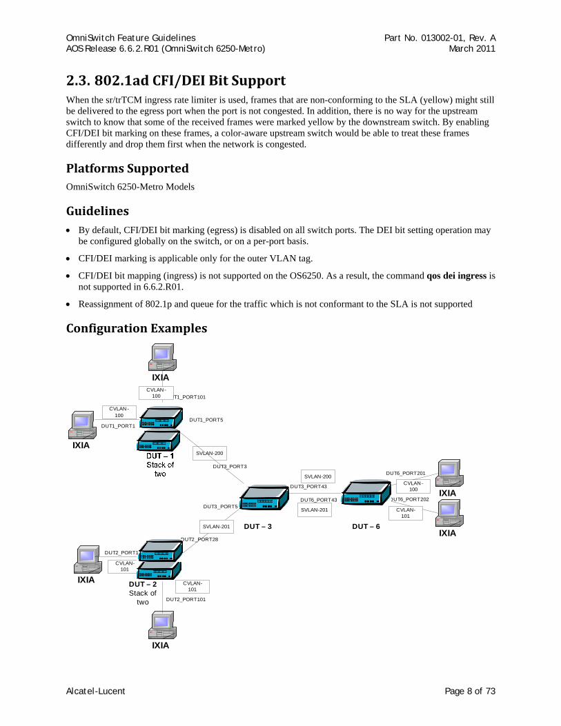
In this sample configuration,
• CVLAN 100 and SVLAN 2000 are configured on DUT-1, DUT-3 and DUT-6.
• A policy rule with policy condition CIR 10M and PIR 5M is configured on DUT1.
• DEI bit marking is enabled on egress NNI of DUT-1.
• Traffic is sent with VLAN 100 at wire rate from one IXIA port that is connected to DUT-1.
• The traffic is then checked on the IXIA port that is connected to DUT-6.
• The received traffic should be 15M (CIR + PIR). In 15M traffic the yellow traffic should be identified by the DEI bit setting. Remaining traffic should drop on DUT-1.
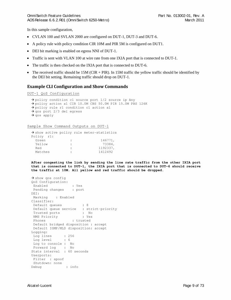
Example CLI Configuration and Show Commands DUT-1 QoS Configuration
policy condition c1 source port 1/2 source ip Any policy action a1 CIR 10.0M CBS 50.0M PIR 15.0M PBS 126K policy rule r1 condition c1 action a1 qos port 2/3 dei egress qos apply
Sample Show Command Outputs on DUT-1
show active policy rule meter-statistics Policy r1: Green : 146771, Yellow : 73384, Red : 1192337, Matches : 1412492
After congesting the link by sending the line rate traffic from the other IXIA port that is connected to DUT-1, the IXIA port that is connected to DUT-6 should receive the traffic at 10M. All yellow and red traffic should be dropped.
show qos config QoS Configuration: Enabled : Yes Pending changes : port DEI: Marking : Enabled Classifier: Default queues : 8 Default queue service : strict-priority Trusted ports : No NMS Priority : Yes Phones : trusted Default bridged disposition : accept Default IGMP/MLD disposition: accept Logging: Log lines : 256 Log level : 6 Log to console : No Forward log : No Stats interval : 60 seconds Userports: Filter : spoof Shutdown: none Debug : info
Alcatel-Lucent Page 9 of 73
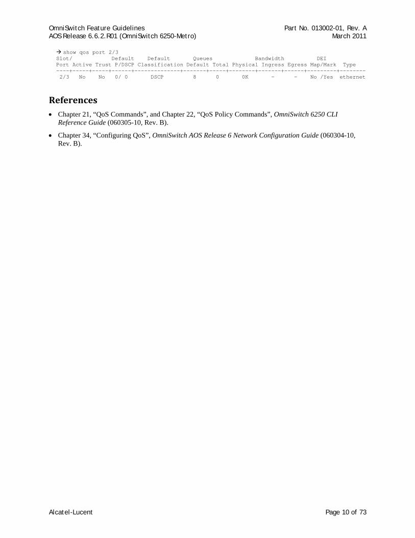
OmniSwitch Feature Guidelines Part No. 013002-01, Rev. A AOS Release 6.6.2.R01 (OmniSwitch 6250-Metro) March 2011
show qos port 2/3 Slot/ Default Default Queues Bandwidth DEI Port Active Trust P/DSCP Classification Default Total Physical Ingress Egress Map/Mark Type ----+-----+-----+------+--------------+-------+-----+--------+-------+------+---------+-------- 2/3 No No 0/ 0 DSCP 8 0 0K - - No /Yes ethernet
References • Chapter 21, “QoS Commands”, and Chapter 22, “QoS Policy Commands”, OmniSwitch 6250 CLI
Reference Guide (060305-10, Rev. B).
• Chapter 34, “Configuring QoS”, OmniSwitch AOS Release 6 Network Configuration Guide (060304-10, Rev. B).
Alcatel-Lucent Page 10 of 73
OmniSwitch Feature Guidelines Part No. 013002-01, Rev. A AOS Release 6.6.2.R01 (OmniSwitch 6250-Metro) March 2011
2.4. QoS Egress Port/Queue and Statistics Enhancements The 6.6.2 release provides the ability to display egress CoS queue drop and transmit statistics on a per port basis using existing QoS show commands. The switch supports two Drop Precedence levels (high and low) at the egress level and also supports accounting egress queues stats using the following entry index:
• Egress Port number • Traffic Class (CoS) (0-7) • Drop Precedence (high/low) • Entry Type: counter is for queued or dropped
Counting both byte and packet mode is also supported, so it is possible to display the number of packets and bytes that are passed or dropped per queue per drop precedence.
Platforms Supported OmniSwitch 6250-Metro Models
Guidelines • The OS6250 automatically gathers egress CoS statistics on a per port basis, so there is no user-
configuration required to support this enhancement.
• A new statistics parameter and the ability to specify a port is now available with the qos queue command.
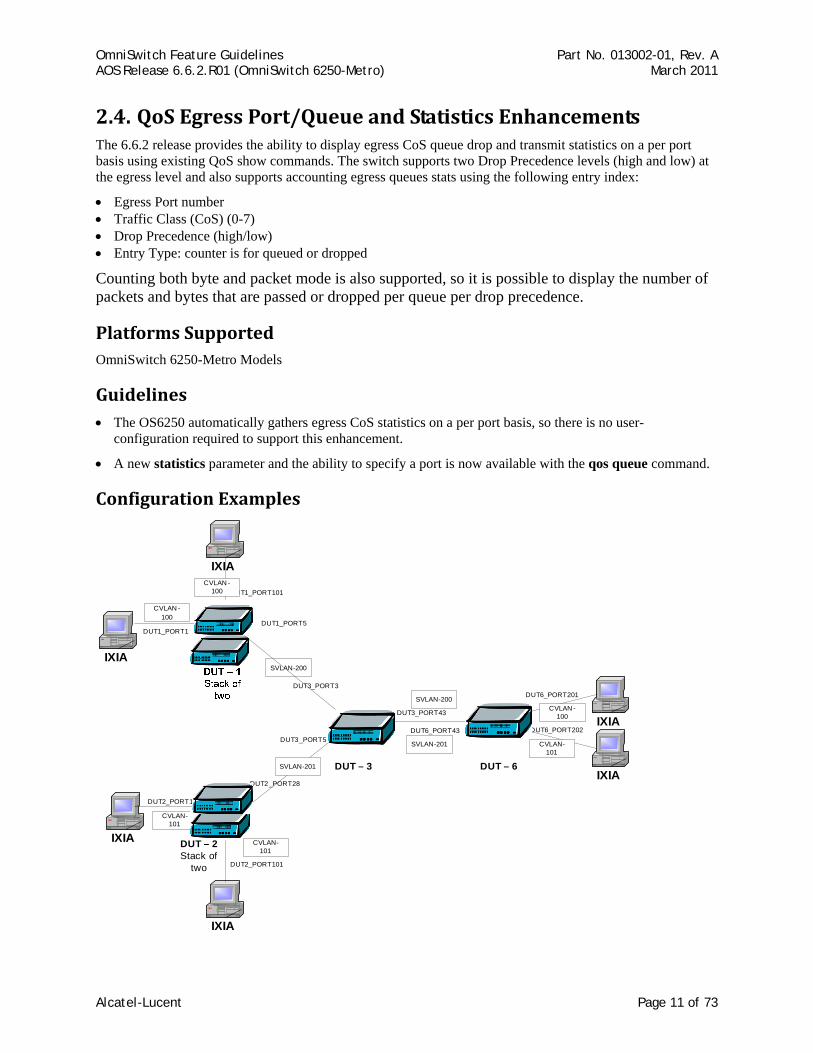
Configuration Examples
IXIA
IXIA
IXIA
IXIA
IXIA
IXIA
DUT1_PORT101
DUT1_PORT1
DUT2_PORT1
DUT2_PORT101
DUT2_PORT28
DUT1_PORT5
DUT3_PORT3
DUT3_PORT5
DUT3_PORT43
DUT6_PORT43
DUT6_PORT201
DUT6_PORT202
CVLAN -100
CVLAN -100
CVLAN -100
CVLAN-101
CVLAN-101
CVLAN-101
SVLAN-201
SVLAN-201
SVLAN-200
SVLAN-200
DUT – 2Stack of
two
DUT – 3 DUT – 6
Alcatel-Lucent Page 11 of 73
OmniSwitch Feature Guidelines Part No. 013002-01, Rev. A AOS Release 6.6.2.R01 (OmniSwitch 6250-Metro) March 2011
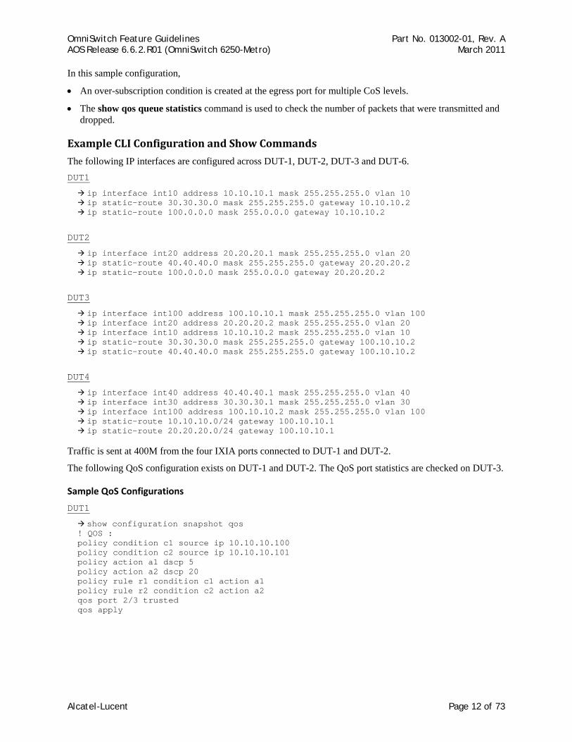
In this sample configuration,
• An over-subscription condition is created at the egress port for multiple CoS levels.
• The show qos queue statistics command is used to check the number of packets that were transmitted and dropped.
Example CLI Configuration and Show Commands
The following IP interfaces are configured across DUT-1, DUT-2, DUT-3 and DUT-6. DUT1
ip interface int10 address 10.10.10.1 mask 255.255.255.0 vlan 10 ip static-route 30.30.30.0 mask 255.255.255.0 gateway 10.10.10.2 ip static-route 100.0.0.0 mask 255.0.0.0 gateway 10.10.10.2
DUT2
ip interface int20 address 20.20.20.1 mask 255.255.255.0 vlan 20 ip static-route 40.40.40.0 mask 255.255.255.0 gateway 20.20.20.2 ip static-route 100.0.0.0 mask 255.0.0.0 gateway 20.20.20.2
DUT3
ip interface int100 address 100.10.10.1 mask 255.255.255.0 vlan 100 ip interface int20 address 20.20.20.2 mask 255.255.255.0 vlan 20 ip interface int10 address 10.10.10.2 mask 255.255.255.0 vlan 10 ip static-route 30.30.30.0 mask 255.255.255.0 gateway 100.10.10.2 ip static-route 40.40.40.0 mask 255.255.255.0 gateway 100.10.10.2
DUT4
ip interface int40 address 40.40.40.1 mask 255.255.255.0 vlan 40 ip interface int30 address 30.30.30.1 mask 255.255.255.0 vlan 30 ip interface int100 address 100.10.10.2 mask 255.255.255.0 vlan 100 ip static-route 10.10.10.0/24 gateway 100.10.10.1 ip static-route 20.20.20.0/24 gateway 100.10.10.1
Traffic is sent at 400M from the four IXIA ports connected to DUT-1 and DUT-2.
The following QoS configuration exists on DUT-1 and DUT-2. The QoS port statistics are checked on DUT-3.
Sample QoS Configurations
DUT1
show configuration snapshot qos ! QOS : policy condition c1 source ip 10.10.10.100 policy condition c2 source ip 10.10.10.101 policy action a1 dscp 5 policy action a2 dscp 20 policy rule r1 condition c1 action a1 policy rule r2 condition c2 action a2 qos port 2/3 trusted qos apply
Alcatel-Lucent Page 12 of 73
OmniSwitch Feature Guidelines Part No. 013002-01, Rev. A AOS Release 6.6.2.R01 (OmniSwitch 6250-Metro) March 2011
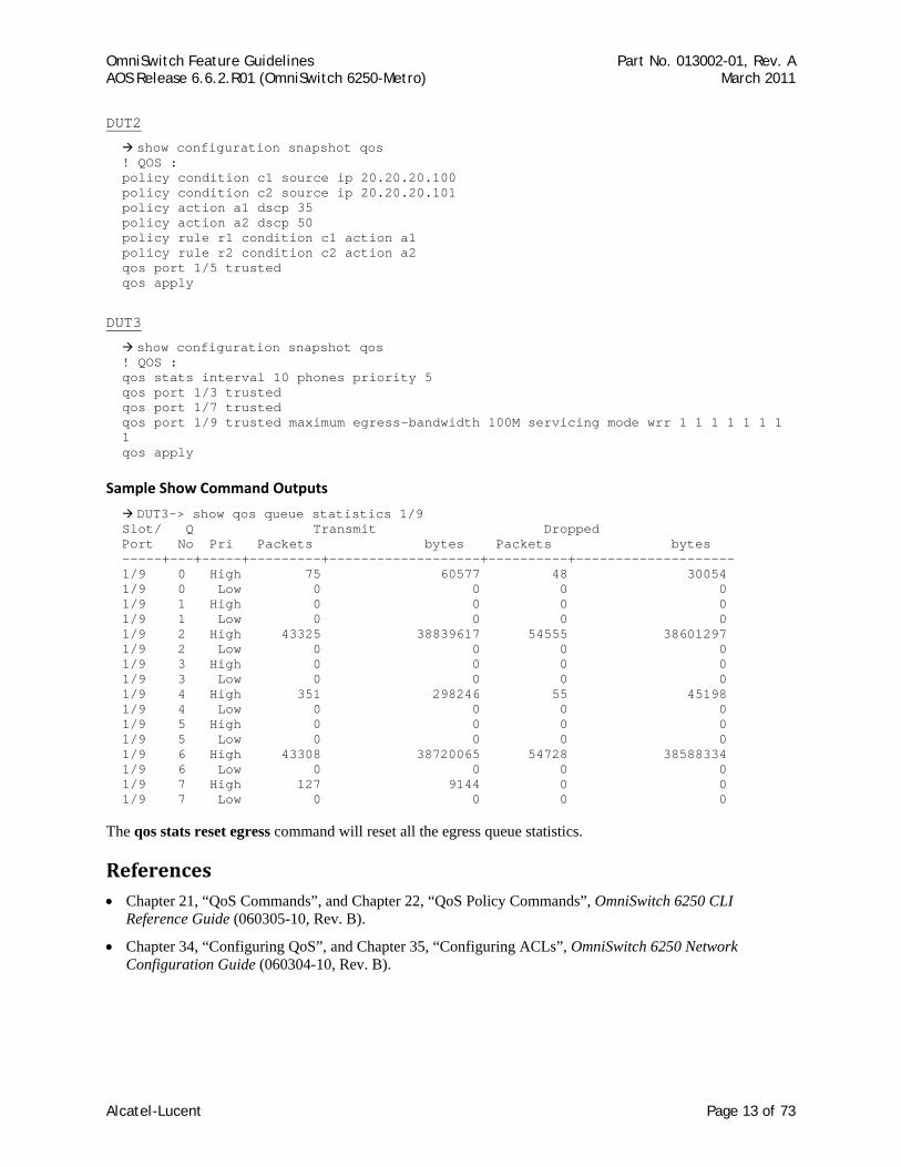
DUT2
show configuration snapshot qos ! QOS : policy condition c1 source ip 20.20.20.100 policy condition c2 source ip 20.20.20.101 policy action a1 dscp 35 policy action a2 dscp 50 policy rule r1 condition c1 action a1 policy rule r2 condition c2 action a2 qos port 1/5 trusted qos apply
DUT3
show configuration snapshot qos ! QOS : qos stats interval 10 phones priority 5 qos port 1/3 trusted qos port 1/7 trusted qos port 1/9 trusted maximum egress-bandwidth 100M servicing mode wrr 1 1 1 1 1 1 1 1 qos apply
Sample Show Command Outputs
DUT3-> show qos queue statistics 1/9 Slot/ Q Transmit Dropped Port No Pri Packets bytes Packets bytes -----+---+-----+---------+-------------------+----------+-------------------- 1/9 0 High 75 60577 48 30054 1/9 0 Low 0 0 0 0 1/9 1 High 0 0 0 0 1/9 1 Low 0 0 0 0 1/9 2 High 43325 38839617 54555 38601297 1/9 2 Low 0 0 0 0 1/9 3 High 0 0 0 0 1/9 3 Low 0 0 0 0 1/9 4 High 351 298246 55 45198 1/9 4 Low 0 0 0 0 1/9 5 High 0 0 0 0 1/9 5 Low 0 0 0 0 1/9 6 High 43308 38720065 54728 38588334 1/9 6 Low 0 0 0 0 1/9 7 High 127 9144 0 0 1/9 7 Low 0 0 0 0
The qos stats reset egress command will reset all the egress queue statistics.
References • Chapter 21, “QoS Commands”, and Chapter 22, “QoS Policy Commands”, OmniSwitch 6250 CLI
Reference Guide (060305-10, Rev. B).
• Chapter 34, “Configuring QoS”, and Chapter 35, “Configuring ACLs”, OmniSwitch 6250 Network Configuration Guide (060304-10, Rev. B).
Alcatel-Lucent Page 13 of 73
OmniSwitch Feature Guidelines Part No. 013002-01, Rev. A AOS Release 6.6.2.R01 (OmniSwitch 6250-Metro) March 2011
2.5. Policy Condition Enhancements The following policy condition enhancements are now available in the 6.6.2.R01 release:
• VLAN IDs can be grouped together into a single VLAN group. Similar to other QoS group types, such as MAC and port groups, creating a VLAN group avoids having to configure a separate policy condition for multiple VLAN IDs.
• Specifying a range of 802.1p values for a policy condition is now supported. A range of values is supported when configuring 802.1p policy conditions. A condition must use either a single 802.1p value or a range of 802.1p values; both are not supported at the same time.
Platforms Supported OmniSwitch 6250-Metro Models
Guidelines • Maximum number of VLAN groups supported is 1024, the same limit that applies to other policy groups.
• The VLAN range and 802.1p range command may program into multiple TCAM entries if it cannot fit into the calculated maskable range.
References • Chapter 21, “QoS Commands”, and Chapter 22, “QoS Policy Commands”, OmniSwitch 6250 CLI
Reference Guide (060305-10, Rev. B).
• Chapter 34, “Configuring QoS”, and Chapter 35, “Configuring ACLs”, OmniSwitch 6250 Network Configuration Guide (060304-10, Rev. B).
Alcatel-Lucent Page 14 of 73
OmniSwitch Feature Guidelines Part No. 013002-01, Rev. A AOS Release 6.6.2.R01 (OmniSwitch 6250-Metro) March 2011
2.6. Map Several Inner DSCP/ToS Values to Same Outer 802.1p QoS policy rules take precedence over Ethernet Services SAP profile settings. As a result, QoS rules can be configured for advanced classification of SAP traffic, such as mapping several DSCP/ToS values to the same outer 802.1p value.
Platforms Supported OmniSwitch 6250-Metro Models.
Guidelines Because QoS policy rules automatically take precedence over SAP profile settings, no specific configuration of the SAP profile is required, as is the case on other OmniSwitch platforms. For example, on an OmniSwitch 6850 running 6.4.3.R01, enforcing QoS rule precedence over SAP profile bandwidth and/or priority settings requires configuring these values as not-assigned.
Configuration Examples
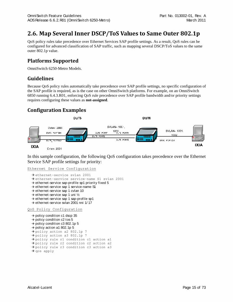
In this sample configuration, the following QoS configuration takes precedence over the Ethernet Service SAP profile settings for priority: Ethernet Service Configuration
ethernet-service svlan 2001 ethernet-service service-name S1 svlan 2001 ethernet-service sap-profile sp1 priority fixed 5 ethernet-service sap 1 service-name S1 ethernet-service sap 1 cvlan 10 ethernet-service sap 1 uni ½ ethernet-service sap 1 sap-profile sp1 ethernet-service svlan 2001 nni 1/17
QoS Policy Configuration
policy condition c1 dscp 35 policy condition c2 tos 5 policy condition c3 802.1p 5 policy action a1 802.1p 5 policy action a2 802.1p 7 policy action a3 802.1p 7 policy rule r1 condition c1 action a1 policy rule r2 condition c2 action a2 policy rule r3 condition c3 action a3 qos apply
Alcatel-Lucent Page 15 of 73
OmniSwitch Feature Guidelines Part No. 013002-01, Rev. A AOS Release 6.6.2.R01 (OmniSwitch 6250-Metro) March 2011
To configure a specific “DSCP to outer 802.1p” mapping:
• Set policy condition(s) with a condition to match the source port and DSCP.
• Set policy action(s) to assign an 802.1p value (this also assigns the internal packet priority)
• Set policy rule(s) for each condition and action
A policy using a map DSCP to 802.1p action may also be used.
The Ethernet SAP can be set to any SAP profile; the Ethernet SAP profile priority assignment is overwritten by the policy rules
To configure a specific “inner to outer 802.1p” mapping:
• Set a SAP profile with a priority “map inner to outer” and assign this profile to the Ethernet SAP. This is critical since the policy condition does not support inner 802.1p. By doing this, the inner and outer 802.1p become the same.
• Set policy condition(s) with a condition to match the “outer” 802.1p
• Set policy action(s) to assign an 802.1p value (this also assigns the internal packet priority)
• Set policy rule(s) for each condition and action
A policy using map 802.1p to 802.1p action may also be used
References • Chapter 21, “QoS Commands”, and Chapter 22, “QoS Policy Commands”, OmniSwitch 6250 CLI
Reference Guide (060305-10, Rev. B).
• Chapter 34, “Configuring QoS”, and Chapter 35, “Configuring ACLs”, OmniSwitch 6250 Network Configuration Guide (060304-10, Rev. B).
Alcatel-Lucent Page 16 of 73
OmniSwitch Feature Guidelines Part No. 013002-01, Rev. A AOS Release 6.6.2.R01 (OmniSwitch 6250-Metro) March 2011
2.7. VLAN Stacking –Tunneling L2 Protocols The Ethernet Services (VLAN Stacking) UNI profile feature allows the transparent tunneling of L2 control frames. However, this feature cannot be deployed in a network where:
• The provider switches process such frames.
• The remote access switch is not an OmniSwitch and does not support transparent tunneling.
To overcome this limitation, the 6.6.2.R01 release provides enhancements to the UNI profile to support a MAC tunneling action that will change the destination MAC address of the L2 control frames to a unique tunnel MAC address.
In addition to MAC tunneling from UNI to NNI, this feature also includes a de-tunnel operation that is performed when the MAC-tunneled L2 control frame is received on a NNI port; the destination MAC address is changed back to the functional MAC address of the L2 control frame.
By default, a global tunnel MAC address of 01:00:0C:CD:CD:D0 is used for the MAC-tunnel actions. The default tunnel MAC address can be changed on a per-UNI profile basis.
The UNI profile enhancements in this release also add support for the following protocols:
• 802.3ad (LACP)
• 802.3ah (OAM)
• LACP Marker
• Cisco PAPG, CDP, DTP, VTP, PVST, VLAN BRIDGE and FAST UPLINK
Platforms Supported OmniSwitch 6250-Metro Models
Guidelines • The feature is only supported on VLAN Stacking UNI ports.
• The existing ethernet-service uni-profile command was updated to include parameters for the additional protocols now supported and parameters to configure the tunnel MAC operation. See Chapter 32, “VLAN Stacking Commands”, in the OmniSwitch 6250 CLI Reference Guide for more information.
• MAC tunneling is only supported in software, whereas the discard and tunnel actions (i.e. transparent tunneling) are supported in hardware. However, when L2 protocols that have the same functional MAC address (802.3ad/802.3ah, Cisco protocols) are set with different actions, the processing of such protocols will always be in software. For example, when 802.3ad is set to tunnel and 802.3ah is set to discard, the tunnel and discard is done in software.
• The MAC tunnel action (same for tunnel action) allows flooding of the L2 control frame from UNI to UNI and NNI to NNI.
• Overall software processing is limited to 512 packets per second for tunneling and de-tunneling L2 protocol packets.
• Rate limiting is done only for packets ingressing on a UNI, so if more than 1000 control packets are sent (512 on UNI and another 512 on NNI) the CPU would spike.
• No port-shutdown when the receiving rate of a L2 protocol on a port exceeds the rate limit.
• The Cisco protocols can only be tunneled or discarded; no peer action. The exception is UDLD.
Alcatel-Lucent Page 17 of 73
OmniSwitch Feature Guidelines Part No. 013002-01, Rev. A AOS Release 6.6.2.R01 (OmniSwitch 6250-Metro) March 2011
• Configuring a tunnel MAC that is within a multicast MAC range is not allowed.
• Configuring a tunnel MAC that is a broadcast address is not allowed.
• The software tunneling does not provide any statistics. This can be achieved by policy rules.
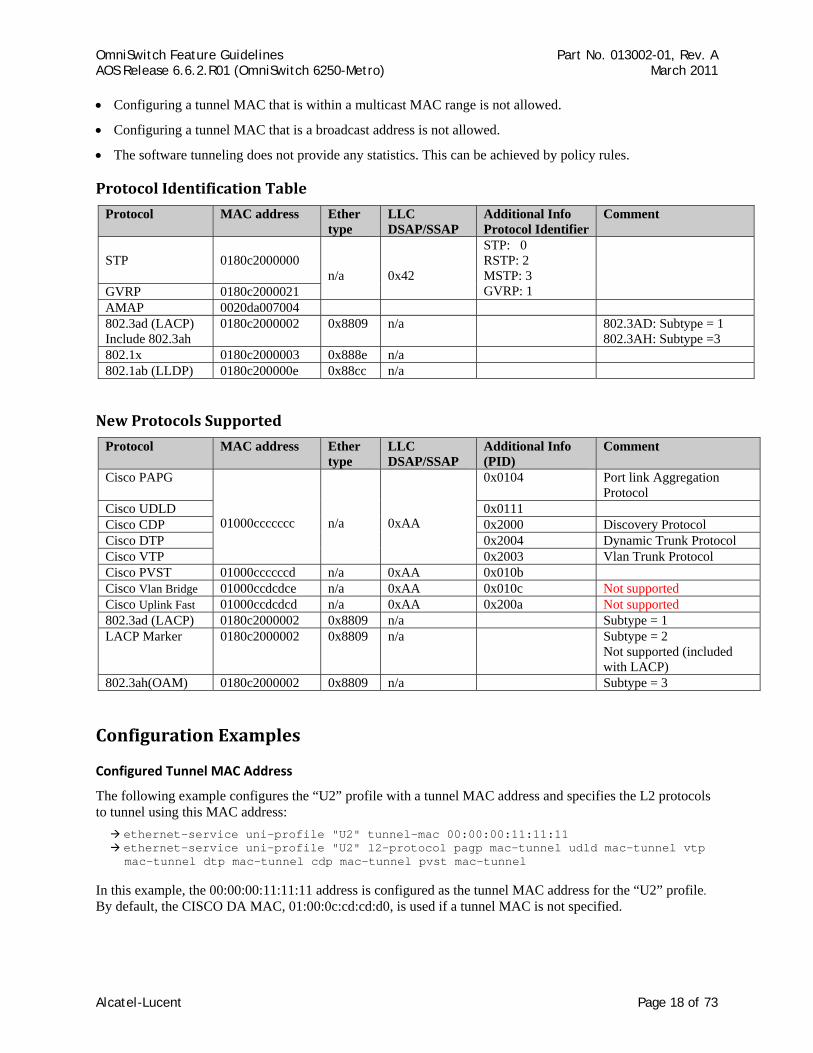
Protocol Identification Table
Protocol MAC address Ether type
LLC DSAP/SSAP
Additional Info Protocol Identifier
Comment
STP
0180c2000000
n/a
0x42
STP: 0 RSTP: 2 MSTP: 3 GVRP: 1
GVRP 0180c2000021 AMAP 0020da007004 802.3ad (LACP) Include 802.3ah
0180c2000002 0x8809 n/a 802.3AD: Subtype = 1 802.3AH: Subtype =3
802.1x 0180c2000003 0x888e n/a 802.1ab (LLDP) 0180c200000e 0x88cc n/a
New Protocols Supported
Protocol MAC address Ether type
LLC DSAP/SSAP
Additional Info (PID)
Comment
Cisco PAPG 01000ccccccc
n/a
0xAA
0x0104 Port link Aggregation Protocol
Cisco UDLD 0x0111 Cisco CDP 0x2000 Discovery Protocol Cisco DTP 0x2004 Dynamic Trunk Protocol Cisco VTP 0x2003 Vlan Trunk Protocol Cisco PVST 01000ccccccd n/a 0xAA 0x010b Cisco Vlan Bridge 01000ccdcdce n/a 0xAA 0x010c Not supported Cisco Uplink Fast 01000ccdcdcd n/a 0xAA 0x200a Not supported 802.3ad (LACP) 0180c2000002 0x8809 n/a Subtype = 1 LACP Marker 0180c2000002 0x8809 n/a Subtype = 2
Not supported (included with LACP)
802.3ah(OAM) 0180c2000002 0x8809 n/a Subtype = 3
Configuration Examples
Configured Tunnel MAC Address
The following example configures the “U2” profile with a tunnel MAC address and specifies the L2 protocols to tunnel using this MAC address:
ethernet-service uni-profile "U2" tunnel-mac 00:00:00:11:11:11 ethernet-service uni-profile "U2" l2-protocol pagp mac-tunnel udld mac-tunnel vtp mac-tunnel dtp mac-tunnel cdp mac-tunnel pvst mac-tunnel
In this example, the 00:00:00:11:11:11 address is configured as the tunnel MAC address for the “U2” profile. By default, the CISCO DA MAC, 01:00:0c:cd:cd:d0, is used if a tunnel MAC is not specified.
Alcatel-Lucent Page 18 of 73
OmniSwitch Feature Guidelines Part No. 013002-01, Rev. A AOS Release 6.6.2.R01 (OmniSwitch 6250-Metro) March 2011
Default Tunnel MAC Address
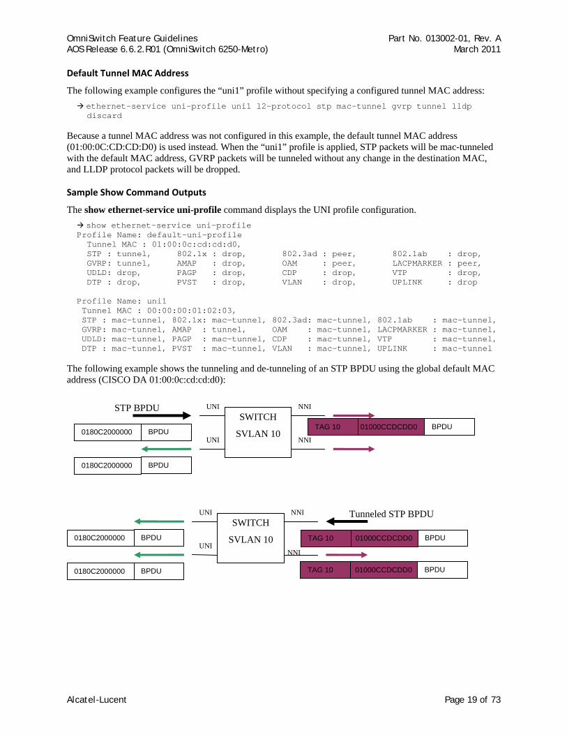
The following example configures the “uni1” profile without specifying a configured tunnel MAC address: ethernet-service uni-profile uni1 l2-protocol stp mac-tunnel gvrp tunnel lldp discard
Because a tunnel MAC address was not configured in this example, the default tunnel MAC address (01:00:0C:CD:CD:D0) is used instead. When the “uni1” profile is applied, STP packets will be mac-tunneled with the default MAC address, GVRP packets will be tunneled without any change in the destination MAC, and LLDP protocol packets will be dropped.
Sample Show Command Outputs
The show ethernet-service uni-profile command displays the UNI profile configuration. show ethernet-service uni-profile
Profile Name: default-uni-profile Tunnel MAC : 01:00:0c:cd:cd:d0, STP : tunnel, 802.1x : drop, 802.3ad : peer, 802.1ab : drop, GVRP: tunnel, AMAP : drop, OAM : peer, LACPMARKER : peer, UDLD: drop, PAGP : drop, CDP : drop, VTP : drop, DTP : drop, PVST : drop, VLAN : drop, UPLINK : drop Profile Name: uni1 Tunnel MAC : 00:00:00:01:02:03, STP : mac-tunnel, 802.1x: mac-tunnel, 802.3ad: mac-tunnel, 802.1ab : mac-tunnel, GVRP: mac-tunnel, AMAP : tunnel, OAM : mac-tunnel, LACPMARKER : mac-tunnel, UDLD: mac-tunnel, PAGP : mac-tunnel, CDP : mac-tunnel, VTP : mac-tunnel, DTP : mac-tunnel, PVST : mac-tunnel, VLAN : mac-tunnel, UPLINK : mac-tunnel
The following example shows the tunneling and de-tunneling of an STP BPDU using the global default MAC address (CISCO DA 01:00:0c:cd:cd:d0):
NNI
NNI
UNI
UNI SWITCH
SVLAN 10
Tunneled STP BPDU
BPDU 0180C2000000
BPDU 0180C2000000 BPDU 01000CCDCDD0 TAG 10
BPDU 01000CCDCDD0 TAG 10
NNI
NNI
UNI
UNI SWITCH
SVLAN 10
STP BPDU
BPDU 0180C2000000
BPDU 0180C2000000 BPDU 01000CCDCDD0 TAG 10
Alcatel-Lucent Page 19 of 73

OmniSwitch Feature Guidelines Part No. 013002-01, Rev. A AOS Release 6.6.2.R01 (OmniSwitch 6250-Metro) March 2011
References • Chapter 32, “VLAN Stacking Commands”, OmniSwitch 6250 CLI Reference Guide (060305-10, Rev. B).
• Chapter 9, “Configuring VLAN Stacking”, OmniSwitch 6250 Network Configuration Guide (060304-10, Rev. B).
Alcatel-Lucent Page 20 of 73
OmniSwitch Feature Guidelines Part No. 013002-01, Rev. A AOS Release 6.6.2.R01 (OmniSwitch 6250-Metro) March 2011
2.8. Advanced (Hardware) Ethernet Loopback An advanced Ethernet loopback test function is available to perform In-Service and Out-of-Service throughput testing during initial turn-up or on-the-fly in an active network. The loopback tests can be used to validate the configured Service Level Agreements (SLAs) and QoS parameters that are associated with a service or a flow.
The loopback test capability provided allows the use of an external test head to send traffic at wire-rate speed to a specific switch port which then loops the traffic back to the test head. The test head measures and collects statistics on frame loss, delay, and latency of the loopback traffic.
There are two types of loopback tests supported with this implementation: inward loopback and outward loopback. The inward test loops back test head frames ingressing on a given port. The outward test loops back test head frames egressing on a given port.
The advanced Ethernet loopback test function is designed for use with an external test head device. The CPE Test Head feature also introduced with the 6.6.2.R01 release allows the OmniSwitch 6250-Metro switch to generate and analyze test traffic. An external test device is not required. See ???? for more information.
Platforms Supported OmniSwitch 6250-Metro Models
Guidelines
Advanced Ethernet Loopback Implementation Differences
The 6.6.2.R01 implementation of the advanced Ethernet loopback functionality differs from the 6.4.3.R01 implementation as follows:
• The loopback operation supports L2 IP and non-IP test frame types, not just L2 IP frames.
• If the loopback port is administratively down, the Egress loopback test cannot start. For example: loopback-test Test1 enable
ERROR: Hardware Loopback test can not be started as the port 1/15 is admin down
• When the Egress loopback test is running, an admin up or admin down of the port is not allowed. For example:
interfaces 1/15 admin down ERROR: Hardware Loopback is running on port 1/15
• If the port is physically disconnected during a loopback test operation, the test is not affected. The link change event is not received when a port is actively running the test. Hardware database entries are not cleared as a result of this type of link down event.
• An optional SAP ID parameter was added to the loopback-test CLI command for configuring an egress loopback test. Since it is possible for multiple SAPs to be associated with the same UNI port, entering a SAP ID with this command identifies a specific SAP for the test. If no SAP ID is specified, the SAP with the lowest ID is used. See the Optional SAP ID Parameter section for more information about configuring the SAP ID.
Configuration Notes
• The loopback test profile specifies the switch attributes that are required to conduct an inward or outward loopback operation on a switch port. Up to eight profiles are supported.
• The loopback operation is not active until the loopback profile is enabled. A separate CLI command, loopback-test profile_name {enable | disable}, is used to start and stop the loopback operation.
Alcatel-Lucent Page 21 of 73
OmniSwitch Feature Guidelines Part No. 013002-01, Rev. A AOS Release 6.6.2.R01 (OmniSwitch 6250-Metro) March 2011
• Once a UNI or NNI port is designated as a loopback port, the port is no longer eligible to participate in other switch functions.
• An outward loopback port goes “out-of-service” and will no longer carry customer traffic but remains active for test frame traffic. However, an inward loopback port remains “in-service” and will continue to carry customer traffic as well as test frame traffic.
• Both IP and non-IP test frames are supported. However, only L2 tests are supported; test frames are not routed. The loopback operation will only swap the source and destination MAC addresses of bridged test frames.
• Configuring an inward and an outward profile with the same port is not allowed. In addition, configuring a profile for a port that is a member of a link aggregate is not supported.
• Each loopback test is associated with one VLAN; using multiple VLANs is not supported.
• The switch creates a static MAC address entry for the egress port when the outward loopback profile is applied on that port. The static address created is the destination MAC address specified in the profile. If the switch receives a non-test frame that contains the same MAC address, both the test and non-test frames are filtered even if they were received on different ports.
• If the MAC addresses specified in the loopback test profile are actual network address (for example, 02:da:95:e1:22:10, not aa:aa:aa:aa:aa:aa), flush the MAC address table for the switch when the loopback test is finished.
• Only the profile configuration is stored in the boot.cfg file, not the commands to enable or disable the profile status. As a result, the profile status must be manually enabled after a system reload or CMM takeover.
Optional SAP ID Parameter
• The loopback-test command includes an optional sap-id parameter that is used to configure an egress loopback test. Specifying a SAP ID identifies which SAP to apply to the UNI or NNI port on which the test will run. If no SAP ID is entered, the SAP with the lowest ID number is used by default.
• The SAP ID is used to determine bandwidth and not the CVLAN. Traffic tagged with any CVLAN ID that is associated with the SAP is looped back, due to the fact that the advanced Ethernet loopback feature does not identify which traffic to loop back. As a result, even unwanted traffic coming into the SVLAN is looped back.
• For Egress NNI and Egress UNI in preserve mode, the SAP ID option determines the mode (preserve) and also the bandwidth applied on that profile.
• For Egress NNI and Egress UNI in translate mode, the SAP ID option determines the mode (translate) and to get single tag loopback traffic.
• When configuring an egress loopback test, specify the SAP ID that is associated with the CVLAN for which test traffic is generated. The hardware loopback feature does not check for any mismatch between the SAP ID specified and the CVLAN ID used for the test.
• Do not change the encapsulation mode for the input SAP when an egress loopback test is running.
• The SVLAN priority for a test frame ingressing on the UNI port is derived from the SAP profile, where as CVLAN priority is not changed. The looped back test frame priority retains the native priority set in the original packet.
Alcatel-Lucent Page 22 of 73
OmniSwitch Feature Guidelines Part No. 013002-01, Rev. A AOS Release 6.6.2.R01 (OmniSwitch 6250-Metro) March 2011
Configuration Examples This section provides configuration examples that illustrate how the Advanced Ethernet Loopback feature is configured and used in a typical network setup.
Example 1: Sample Loopback Test Configuration
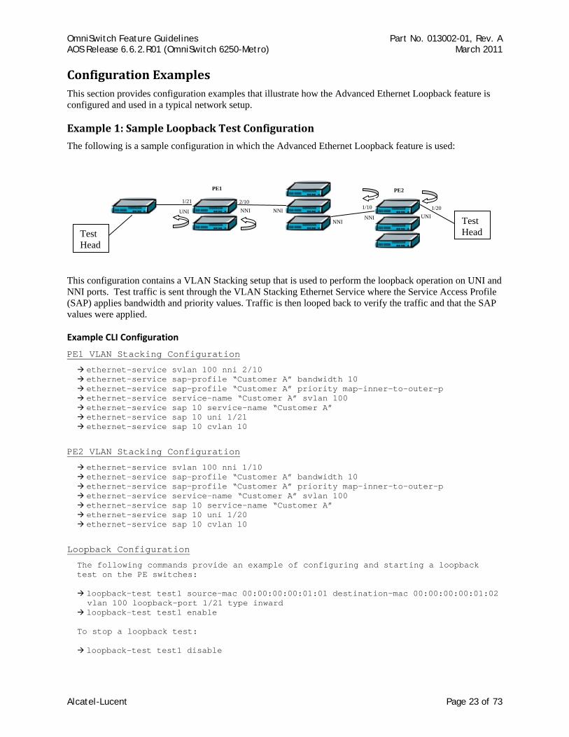
The following is a sample configuration in which the Advanced Ethernet Loopback feature is used:
This configuration contains a VLAN Stacking setup that is used to perform the loopback operation on UNI and NNI ports. Test traffic is sent through the VLAN Stacking Ethernet Service where the Service Access Profile (SAP) applies bandwidth and priority values. Traffic is then looped back to verify the traffic and that the SAP values were applied.
Example CLI Configuration
PE1 VLAN Stacking Configuration
ethernet-service svlan 100 nni 2/10 ethernet-service sap-profile “Customer A” bandwidth 10 ethernet-service sap-profile “Customer A” priority map-inner-to-outer-p ethernet-service service-name “Customer A” svlan 100 ethernet-service sap 10 service-name “Customer A” ethernet-service sap 10 uni 1/21 ethernet-service sap 10 cvlan 10
PE2 VLAN Stacking Configuration
ethernet-service svlan 100 nni 1/10 ethernet-service sap-profile “Customer A” bandwidth 10 ethernet-service sap-profile “Customer A” priority map-inner-to-outer-p ethernet-service service-name “Customer A” svlan 100 ethernet-service sap 10 service-name “Customer A” ethernet-service sap 10 uni 1/20 ethernet-service sap 10 cvlan 10
Loopback Configuration
The following commands provide an example of configuring and starting a loopback test on the PE switches:
loopback-test test1 source-mac 00:00:00:00:01:01 destination-mac 00:00:00:00:01:02 vlan 100 loopback-port 1/21 type inward
loopback-test test1 enable To stop a loopback test:
loopback-test test1 disable
1/20 UNI Test
Head
PE1 PE2
1/10
NNINNI
NNIUNI
Test Head
2/101/21
NNI
Alcatel-Lucent Page 23 of 73
OmniSwitch Feature Guidelines Part No. 013002-01, Rev. A AOS Release 6.6.2.R01 (OmniSwitch 6250-Metro) March 2011
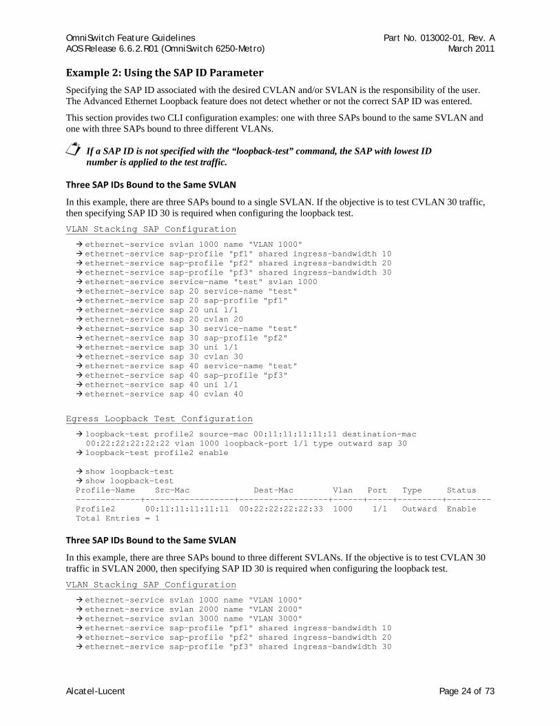
Example 2: Using the SAP ID Parameter
Specifying the SAP ID associated with the desired CVLAN and/or SVLAN is the responsibility of the user. The Advanced Ethernet Loopback feature does not detect whether or not the correct SAP ID was entered.
This section provides two CLI configuration examples: one with three SAPs bound to the same SVLAN and one with three SAPs bound to three different VLANs.
If a SAP ID is not specified with the “loopback-test” command, the SAP with lowest ID number is applied to the test traffic.
Three SAP IDs Bound to the Same SVLAN
In this example, there are three SAPs bound to a single SVLAN. If the objective is to test CVLAN 30 traffic, then specifying SAP ID 30 is required when configuring the loopback test. VLAN Stacking SAP Configuration
ethernet-service svlan 1000 name "VLAN 1000" ethernet-service sap-profile "pf1" shared ingress-bandwidth 10 ethernet-service sap-profile "pf2" shared ingress-bandwidth 20 ethernet-service sap-profile "pf3" shared ingress-bandwidth 30 ethernet-service service-name "test" svlan 1000 ethernet-service sap 20 service-name "test" ethernet-service sap 20 sap-profile "pf1" ethernet-service sap 20 uni 1/1 ethernet-service sap 20 cvlan 20 ethernet-service sap 30 service-name "test" ethernet-service sap 30 sap-profile "pf2" ethernet-service sap 30 uni 1/1 ethernet-service sap 30 cvlan 30 ethernet-service sap 40 service-name "test" ethernet-service sap 40 sap-profile "pf3" ethernet-service sap 40 uni 1/1 ethernet-service sap 40 cvlan 40
Egress Loopback Test Configuration
loopback-test profile2 source-mac 00:11:11:11:11:11 destination-mac 00:22:22:22:22:22 vlan 1000 loopback-port 1/1 type outward sap 30
loopback-test profile2 enable
show loopback-test show loopback-test
Profile-Name Src-Mac Dest-Mac Vlan Port Type Status -------------+------------------+------------------+------+-----+---------+--------- Profile2 00:11:11:11:11:11 00:22:22:22:22:33 1000 1/1 Outward Enable Total Entries = 1
Three SAP IDs Bound to the Same SVLAN
In this example, there are three SAPs bound to three different SVLANs. If the objective is to test CVLAN 30 traffic in SVLAN 2000, then specifying SAP ID 30 is required when configuring the loopback test. VLAN Stacking SAP Configuration
ethernet-service svlan 1000 name "VLAN 1000" ethernet-service svlan 2000 name "VLAN 2000" ethernet-service svlan 3000 name "VLAN 3000" ethernet-service sap-profile "pf1" shared ingress-bandwidth 10 ethernet-service sap-profile "pf2" shared ingress-bandwidth 20 ethernet-service sap-profile "pf3" shared ingress-bandwidth 30
Alcatel-Lucent Page 24 of 73
OmniSwitch Feature Guidelines Part No. 013002-01, Rev. A AOS Release 6.6.2.R01 (OmniSwitch 6250-Metro) March 2011
ethernet-service service-name "test1" svlan 1000 ethernet-service sap 20 service-name "test1" ethernet-service sap 20 sap-profile "pf1" ethernet-service sap 20 uni 1/1 ethernet-service sap 20 cvlan 20 ethernet-service service-name "test2" svlan 2000 ethernet-service sap 30 service-name "test2" ethernet-service sap 30 sap-profile "pf2" ethernet-service sap 30 uni 1/1 ethernet-service sap 30 cvlan 30 ethernet-service service-name "test3" svlan 3000 ethernet-service sap 40 service-name "test3" ethernet-service sap 40 sap-profile "pf3" ethernet-service sap 40 uni 1/1 ethernet-service sap 40 cvlan 40
Egress Loopback Test Configuration
loopback-test profile1 source-mac 00:11:11:11:11:11 destination-mac 00:22:22:22:22:33 vlan 2000 loopback-port 1/1 type outward sap 30
loopback-test profile1 enable
show loopback-test Profile-Name Src-Mac Dest-Mac Vlan Port Type Status -------------+------------------+------------------+------+-----+---------+--------- profile1 00:11:11:11:11:11 00:22:22:22:22:33 2000 1/1 Outward Enable Total Entries = 1
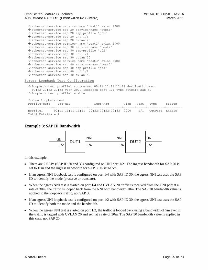
Example 3: SAP ID Bandwidth
DUT1 DUT2UNI1/2
NNI NNI
1/2
UNI
1/4 1/4
In this example,
• There are 2 SAPs (SAP ID 20 and 30) configured on UNI port 1/2. The ingress bandwidth for SAP 20 is set to 10m and the ingress bandwidth for SAP 30 is set to 5m.
• If an egress NNI loopback test is configured on port 1/4 with SAP ID 30, the egress NNI test uses the SAP ID to identify the mode (preserve or translate).
• When the egress NNI test is started on port 1/4 and CVLAN 20 traffic is received from the UNI port at a rate of 30m, the traffic is looped back from the NNI with bandwidth 10m. The SAP 20 bandwidth value is applied to the loopback traffic, not SAP 30.
• If an egress UNI loopback test is configured on port 1/2 with SAP ID 30, the egress UNI test uses the SAP ID to identify both the mode and the bandwidth.
• When the egress UNI test is started on port 1/2, the traffic is looped back using a bandwidth of 5m even if the traffic is tagged with CVLAN 20 and sent at a rate of 30m. The SAP 30 bandwidth value is applied in this case, not SAP 20.
Alcatel-Lucent Page 25 of 73
OmniSwitch Feature Guidelines Part No. 013002-01, Rev. A AOS Release 6.6.2.R01 (OmniSwitch 6250-Metro) March 2011
Example CLI Configuration
VLAN Stacking UNI and NNI Configuration
ethernet-service svlan 1000 name "VLAN 1000" ethernet-service svlan 1000 nni 1/4 ethernet-service sap-profile "pf1" shared ingress-bandwidth 10 ethernet-service sap-profile "pf2" shared ingress-bandwidth 5 ethernet-service service-name "test1" svlan 1000 ethernet-service sap 20 service-name "test1" ethernet-service sap 20 sap-profile "pf1" ethernet-service sap 20 uni 1/2 ethernet-service sap 20 cvlan 20 ethernet-service service-name "test2" svlan 1000 ethernet-service sap 30 service-name "test2" ethernet-service sap 30 sap-profile "pf2" ethernet-service sap 30 uni 1/2 ethernet-service sap 30 cvlan 30
Egress NNI Loopback Test Configuration on Switch 1
loopback-test profile1 source-mac 00:11:11:11:11:11 destination-mac 00:22:22:22:22:33 vlan 1000 loopback-port 1/4 type outward sap 30
show loopback-test
Profile-Name Src-Mac Dest-Mac Vlan Port Type Status -------------+------------------+------------------+------+-----+---------+--------- profile1 00:11:11:11:11:11 00:22:22:22:22:33 1000 1/4 Outward Config Total Entries = 1
loopback-test profile1 enable
show loopback-test Profile-Name Src-Mac Dest-Mac Vlan Port Type Status -------------+------------------+------------------+------+-----+---------+--------- profile1 00:11:11:11:11:11 00:22:22:22:22:33 1000 1/4 Outward Enable Total Entries = 1
Egress UNI Loopback Test Configuration on Switch 2
loopback-test profile2 source-mac 00:11:11:11:11:11 destination-mac 00:22:22:22:22:33 vlan 1000 loopback-port 1/2 type outward sap 30
loopback-test profile2 enable
show loopback-test Profile-Name Src-Mac Dest-Mac Vlan Port Type Status -------------+------------------+------------------+------+-----+---------+--------- Profile2 00:11:11:11:11:11 00:22:22:22:22:33 1000 1/2 Outward Enable Total Entries = 1
References • Chapter 32, “VLAN Stacking Commands”, OmniSwitch 6250 CLI Reference Guide (060305-10, Rev. B).
• Chapter 9, “Configuring VLAN Stacking”, OmniSwitch 6250 Network Configuration Guide (060304-10, Rev. B).
Alcatel-Lucent Page 26 of 73

OmniSwitch Feature Guidelines Part No. 013002-01, Rev. A AOS Release 6.6.2.R01 (OmniSwitch 6250-Metro) March 2011
2.9. CPE Test Head The Customer Provider Edge (CPE) Test Head traffic generator and analyzer is a Test-OAM (Operation, Administration and Maintenance) tool used in the Metro Ethernet Network to validate the customer Service Level Agreements (SLA). This functionality allows the operator to test and validate the Metro Ethernet Network between customer end points, which is critical when provisioning or troubleshooting network services.
This feature allows the service provider to perform the following tasks without the need for an external test head device:
• Generate specific flow-based traffic across the customer’s Ethernet Virtual Circuit (EVC) to help identify flow-based issues.
• Identify the impact of QoS settings (SAP profile or QoS policies) on the overall traffic.
• Confirm throughput across the provider network.
• Debug flow-specific traffic forwarding across the provider network.
• Analyze the behavior of various user-defined traffic patterns across the provider network.
• Perform the handover testing after initial deployment.
• Perform on-demand testing and results monitoring using a central entity.
Platforms Supported OmniSwitch 6250-Metro Models
Guidelines • This implementation of CPE Test Head supports the ability to run unidirectional, ingress tests.
• Only frame loss is supported, delay and jitter measurement is not supported
• Only bridged frames (can be IP frames), no routing.
• Make sure the same test profile name (test ID) is used on the generator and analyzer switch.
• A switch can only perform one role (generator or analyzer) for a specific test.
• Up to 32 test profiles are allowed per switch, but only one test can be active for the switch at a given time.
• Regular traffic is disrupted on the ingress UNI port that is used to generate the test traffic. However, traffic on other UNI ports associated with the same SAP profile is not disrupted. Therefore, running the test on a UNI port that is not in use is recommended.
• In the first few initial seconds of the test there is burst and then only the shaper shapes to the configured rate value. As a result, the generation rate will be higher than the configured rate during these initial few seconds.
• There is no PHY in the uplink port. So when the uplink port is a generator port, the frames (data and control) coming to the port cannot be dropped as a PHY down is not possible.
• This feature does not work during takeover. If a CPE test is running and a takeover occurs, the NI on which the test is running will abort the test and clear its context.
• If a CPE test is running and an NI is extracted, a switch reboot is required and test results are not deterministic in this case. Although the CPE Test Head configuration is saved in the CMM database, the SAM/CLI has to activate the test in a required pattern. If any NI goes down, the test is aborted.
Alcatel-Lucent Page 27 of 73
OmniSwitch Feature Guidelines Part No. 013002-01, Rev. A AOS Release 6.6.2.R01 (OmniSwitch 6250-Metro) March 2011
• If this test is running and there is a network topology change, packet drops may occur.
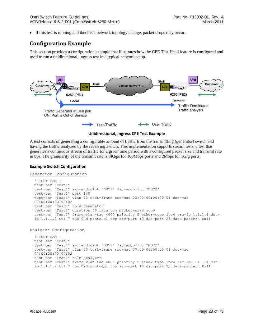
Configuration Example This section provides a configuration example that illustrates how the CPE Test Head feature is configured and used to run a unidirectional, ingress test in a typical network setup.
Unidirectional, Ingress CPE Test Example
A test consists of generating a configurable amount of traffic from the transmitting (generator) switch and having the traffic analyzed by the receiving switch. This implementation supports stream tests; a test that generates a continuous stream of traffic for a given time period with a configured packet size and transmit rate in bps. The granularity of the transmit rate is 8Kbps for 100Mbps ports and 2Mbps for 1Gig ports.
Example Switch Configuration
Generator Configuration
! TEST-OAM : test-oam "Test1" test-oam "Test1" src-endpoint "DUT1" dst-endpoint "DUT2" test-oam "Test1" port 1/5 test-oam "Test1" vlan 20 test-frame src-mac 00:00:00:00:00:01 dst-mac 00:00:00:00:00:02 test-oam "Test1" role generator test-oam "Test1" duration 60 rate 50m packet-size 5000 test-oam "Test1" frame vlan-tag 4000 priority 5 ether-type ipv4 src-ip 1.1.1.1 dst-ip 1.1.1.2 ttl 7 tos 0xd protocol tcp src-port 10 dst-port 25 data-pattern 0x11
Analyzer Configuration
! TEST-OAM : test-oam "Test1" test-oam "Test1" src-endpoint "DUT1" dst-endpoint "DUT2" test-oam "Test1" vlan 20 test-frame src-mac 00:00:00:00:00:01 dst-mac 00:00:00:00:00:02 test-oam "Test1" role analyzer test-oam "Test1" frame vlan-tag 4000 priority 5 ether-type ipv4 src-ip 1.1.1.1 dst-ip 1.1.1.2 ttl 7 tos 0xd protocol tcp src-port 10 dst-port 25 data-pattern 0x11
Traffic Generator at UNI port UNI Port is Out of Service
UNI Customer
N t k
GigE GigE
6250 (PE1)
Local
6250 (PE2)
Remote
Carrier Network Customer
N t kNNI
Traffic Terminated Traffic analysis
User Traffic Test-Traffic
NNI
UNI
Alcatel-Lucent Page 28 of 73
OmniSwitch Feature Guidelines Part No. 013002-01, Rev. A AOS Release 6.6.2.R01 (OmniSwitch 6250-Metro) March 2011
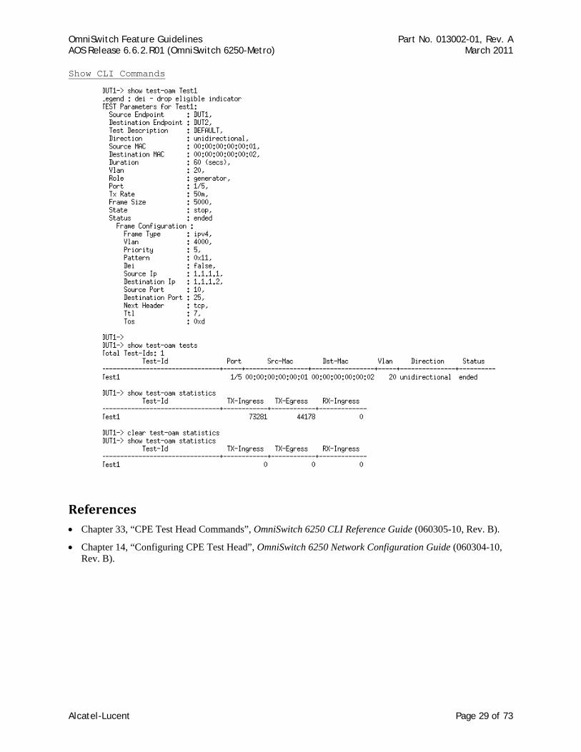
Show CLI Commands
References • Chapter 33, “CPE Test Head Commands”, OmniSwitch 6250 CLI Reference Guide (060305-10, Rev. B).
• Chapter 14, “Configuring CPE Test Head”, OmniSwitch 6250 Network Configuration Guide (060304-10, Rev. B).
Alcatel-Lucent Page 29 of 73
OmniSwitch Feature Guidelines Part No. 013002-01, Rev. A AOS Release 6.6.2.R01 (OmniSwitch 6250-Metro) March 2011
2.10. Ethernet OAM 802.1ag Version 8 and ITU Y1731 IEEE 802.1ag Connectivity Fault Management (CFM) defines protocols and practices for OAM (Operations, Administration and Maintenance) for paths through 802.1 bridges and local area networks (LANs). It is an amendment to IEEE 802.1Q-2005 and was approved in 2007. Note that previous releases of AOS support an earlier version of IEEE 802.1ag (Draft Revision 7).
Also known as Service OAM, the IEEE 802.1ag CFM is used to monitor and troubleshoot end-to-end Ethernet services. This implementation of Ethernet Service OAM supports both IEEE 802.1ag and ITU-T Y.1731 for Connectivity Fault Management (plus performance monitoring provided by ITU-T Y.1731).
In compliance with the ITU-T Y.1731 performance monitoring definition, the OmniSwitch supports Ethernet frame delay measurement (one-way and two-way). However, the OmniSwitch implementation is agnostic to either IEEE 802.1ag or ITU-T Y.1731 in that delay measurement can be performed for maintenance points that comply with either standard.
Platforms Supported OmniSwitch 6250-Metro Models
Guidelines This section contains general information and configuration guidelines for the 6.6.2.R01 implementation of Ethernet OAM (802.1ag, version 8) and support for the ITU-T Y.1731 Recommendation.
Elements of Service OAM
• Maintenance End Points (MEPs) and Maintenance Intermediate Points (MIPs)
MEPs initiate OAM commands. MEPs prevent leakage between domains.
MIPs passively receive and respond to OAM frames.
• Maintenance Association (MA) is a logical connection between 2 or more MEPs.
• Point-to-point MA: logical sub-MA component only between 2 MEPs MA.
• Maintenance Domain: One or more MAs under the same administrative control.
• Maintenance Domain Levels: There are 8 levels defined in 802.1ag:
levels [5, 6, 7] are for customers
levels [3, 4] are for service provider
levels [0, 1, 2] are for operators
Multiple levels are supported for flexibility.
• Connectivity Fault Management: continuity check, loopback, link trace
Connectivity Fault Management
Service OAM Connectivity Fault Management (CFM) consists of three types of messages that are used to help network administrators detect, verify, and isolate when a problem occurs in the network:
• Continuity Check Messages (CCM). These are multicast messages exchanged periodically by MEPs to detect loss of service connectivity between MEPs. These messages are also used by MEPs and MIPs to discover other MEPs within a domain.
Alcatel-Lucent Page 30 of 73
OmniSwitch Feature Guidelines Part No. 013002-01, Rev. A AOS Release 6.6.2.R01 (OmniSwitch 6250-Metro) March 2011
CC messages flow within an MA—for example, a service (VLAN)—and are multicast within a VLAN. A MA can also monitor more than one VLAN and any MEP configured in the MA will inherit the MAID, MD Level, and Primary VID from its MA. Moreover, the selection of which of the MA’s VIDs is the Primary VID can be overridden for a specific MEP.
• Linktrace Messages (LTM). These messages are transmitted by a MEP to trace the path to a destination maintenance point. The receiving maintenance point responds to LTMs with a linktrace reply (LTR). This mechanism is similar to the UDP Trace Route function. The transmission of linktrace messages is requested by an administrator.
• Loopback Messages (LBM). These messages are transmitted by a MEP to a specified MIP or MEP to determine whether or not the maintenance point is reachable. The receiving maintenance point responds to LBMs with a loopback reply (LBR). This mechanism is not used to discover a path to the destination; it is similar to the Ping function. The transmission of loopback messages is requested by an administrator.
Ethernet Service OAM Implementation Differences
The 6.6.2.R01 implementation of Ethernet Service OAM (802.1ag CFM) differs from the previous implementation as follows:
• A single MA will monitor more than one service (VLAN). While creating the MA, only the primary VID is required and the mapping between primary and non-primary VID(s) is stored in the VLAN Table.
• Transmitting the Sender ID TLV is a management action that is controlled by MD, MA, and Default-MD.
• Sender ID TLV now includes the Management Address and the Domain name of the TLV.
• The MD also controls the creating of the MIP. The MA mhfCreation object supersedes the mhfCreation object in the MD table. Both objects are controlled by the 'defer' value of the MA mhfCreation object.
• The Egress Identifier in the LTM frame is sent as LTM Egress Identifier TLV (type is 7).
• The last Egress Identifier and the next Egress Identifier in the LTR frame are sent as LTR Egress Identifier TLV (type is 8).
• LTR flags have changed. Refer to clause 21.9.1 in the standard for details.
• TLV types have changed for Data TLV (from 4 to 3) and Interface Status TLV (from 3 to 4).
• RDI condition has changed. Refer to clause 21.6.1.1 in the standard for details.
• The initiation mechanism for both Loopback and Linktrace messages has changed.
Alcatel-Lucent Page 31 of 73
OmniSwitch Feature Guidelines Part No. 013002-01, Rev. A AOS Release 6.6.2.R01 (OmniSwitch 6250-Metro) March 2011
Interoperability with ITUT Y.1731
Although this implementation of Service OAM supports both IEEE 802.1ag and ITU-T Y.1731 for CFM, the 802.1ag terminology and hierarchy is used for configuring CFM. The following table provides a mapping of 802.1ag terms to the equivalent ITU-T Y.1731 terms:
IEEE 802.1ag v8.1 ITU-T Y.1731 Maintenance Domain (MD) Maintenance Entity (ME) Maintenance Association (MA) Maintenance Entity Group (MEG) Maintenance Endpoint (MEP) MEG Endpoint (MEP) Maintenance Intermediate Point (MIP) MEG Intermediate Point (MIP) Maintenance Domain Level MEG Level
Support for both the IEEE and ITU-T Ethernet CFM standards allows interoperability between OmniSwitch 802.1ag and Y.1731 CFM with the following considerations:
• The OmniSwitch MD format must be configured as “none”, which is now an option provided with the ethoam domain CLI command. For example:
ethoam domain MD1 format none
• When the MD format is “none”, the MD name is not encoded in the MAID and only the format, length, and name of the MD is encoded. Basically, MA in IEEE is analogous to MEG in ITU-T.
• ITU-T Y.1731 uses the “icc-based” format for a MEG, so the OmniSwitch MA format must also be configured to use the “icc-based” format. The ethoam association CLI command now includes an icc-based option. For example:
ethoam association MA1 format icc-based domain MD1 primary-vlan 100
• When the OmniSwitch MA is configured with the “icc-based” format, the MA name is automatically padded with zeros if the name specified is less than 13 characters.
• ITU-T Y.1731 does not include the LTM Egress Identifier TLV or the LTR Egress Identifier TLV. For compatibility with earlier implementations of ITU-T, IEEE does not require that these TLVs be present on received LTMs or LTRs. However, IEEE does require these TLVs to be transmitted in LTMs and LTRs.
• Even though IEEE 802.1ag and ITU-T Y.1731 have the same objective and use the same header format, they do not have the same field definitions.
ITUT Y.1731 Performance Monitoring
The ITU-T Y.1731 Recommendation addresses the need to monitor performance to help enforce customer service level agreements (SLAs). Frame delay (latency) and frame delay variation (jitter) are important performance objectives, especially for those applications (such as voice) that cannot function with a high level of latency or jitter.
This implementation of Service OAM supports Ethernet frame delay measurement (ETH-DM). The ETH-DM feature allows for the configuration of on-demand OAM to measure frame delay and frame delay variation between endpoints.
Frame delay measurement is performed between peer MEPs (measurements to MIPs are not done) within the same MA. Although the OmniSwitch implementation of ETH-DM is compliant with ITU-T Y.1731, delay measurement can be performed for both ITU-T Y.1731 and IEEE 802.1ag MEPs.
Any MEP can initiate or reply to an ETH-DM request, depending on the type of delay measurement requested. There are two types of delay measurements supported: one-way and two-way.
Alcatel-Lucent Page 32 of 73
OmniSwitch Feature Guidelines Part No. 013002-01, Rev. A AOS Release 6.6.2.R01 (OmniSwitch 6250-Metro) March 2011
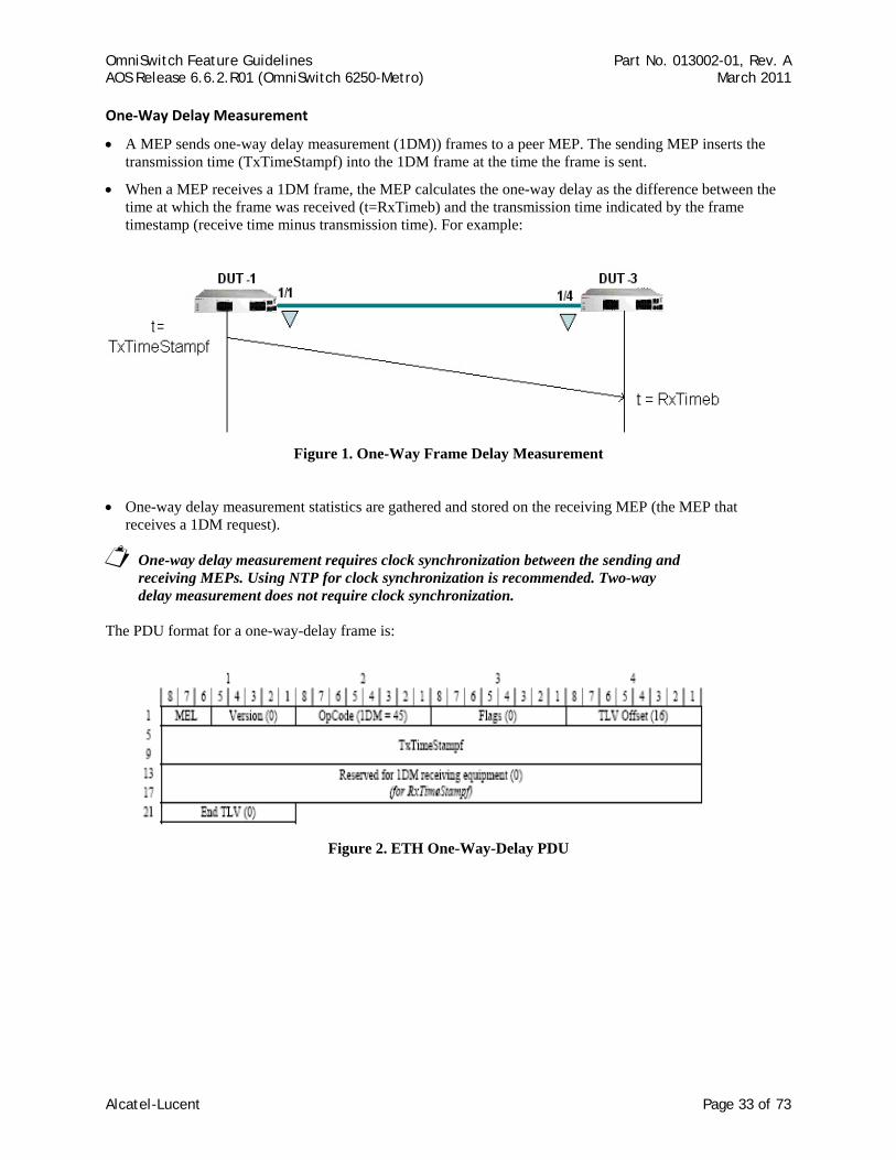
One‐Way Delay Measurement
• A MEP sends one-way delay measurement (1DM)) frames to a peer MEP. The sending MEP inserts the transmission time (TxTimeStampf) into the 1DM frame at the time the frame is sent.
• When a MEP receives a 1DM frame, the MEP calculates the one-way delay as the difference between the time at which the frame was received (t=RxTimeb) and the transmission time indicated by the frame timestamp (receive time minus transmission time). For example:
Figure 1. One-Way Frame Delay Measurement
• One-way delay measurement statistics are gathered and stored on the receiving MEP (the MEP that receives a 1DM request).
One-way delay measurement requires clock synchronization between the sending and receiving MEPs. Using NTP for clock synchronization is recommended. Two-way delay measurement does not require clock synchronization.
The PDU format for a one-way-delay frame is:
Figure 2. ETH One-Way-Delay PDU
Alcatel-Lucent Page 33 of 73
OmniSwitch Feature Guidelines Part No. 013002-01, Rev. A AOS Release 6.6.2.R01 (OmniSwitch 6250-Metro) March 2011
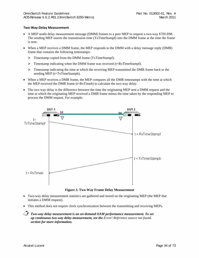
Two‐Way‐Delay Measurement
• A MEP sends delay measurement message (DMM) frames to a peer MEP to request a two-way ETH-DM. The sending MEP inserts the transmission time (TxTimeStampf) into the DMM frame at the time the frame is sent.
• When a MEP receives a DMM frame, the MEP responds to the DMM with a delay message reply (DMR) frame that contains the following timestamps:
Timestamp copied from the DMM frame (TxTimeStampf).
Timestamp indicating when the DMM frame was received (t=RxTimeStampf).
Timestamp indicating the time at which the receiving MEP transmitted the DMR frame back to the sending MEP (t=TxTimeStampb).
• When a MEP receives a DMR frame, the MEP compares all the DMR timestamps with the time at which the MEP received the DMR frame (t=RxTimeb) to calculate the two-way delay.
• The two-way delay is the difference between the time the originating MEP sent a DMM request and the time at which the originating MEP received a DMR frame minus the time taken by the responding MEP to process the DMM request. For example:
Figure 3. Two-Way Frame Delay Measurement
• Two-way delay measurement statistics are gathered and stored on the originating MEP (the MEP that initiates a DMM request).
• This method does not require clock synchronization between the transmitting and receiving MEPs.
Two-way delay measurement is an on-demand OAM performance measurement. To set up continuous two-way delay measurement, see the Error! Reference source not found. section for more information.
Alcatel-Lucent Page 34 of 73
OmniSwitch Feature Guidelines Part No. 013002-01, Rev. A AOS Release 6.6.2.R01 (OmniSwitch 6250-Metro) March 2011
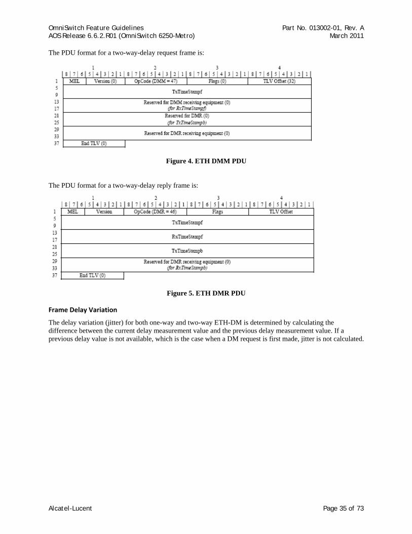
The PDU format for a two-way-delay request frame is:
Figure 4. ETH DMM PDU
The PDU format for a two-way-delay reply frame is:
Figure 5. ETH DMR PDU
Frame Delay Variation
The delay variation (jitter) for both one-way and two-way ETH-DM is determined by calculating the difference between the current delay measurement value and the previous delay measurement value. If a previous delay value is not available, which is the case when a DM request is first made, jitter is not calculated.
Alcatel-Lucent Page 35 of 73
OmniSwitch Feature Guidelines Part No. 013002-01, Rev. A AOS Release 6.6.2.R01 (OmniSwitch 6250-Metro) March 2011
Other Guidelines
• Packet Loss measurement - Dual-ended packet loss measurement in either CCM messages or LMM/LMR messages is not supported. These functions rely on hardware packet generation and accurate ingress and egress service counters.
• Test ETH-Test - One way test signal is not supported. This function implies the generation of a test frame with test pattern (all-0, all-1, CRC) and verification of test frames.
• The following functions are also not supported:
ETH-AIS ETH-LCK ETH-APS ETH-MCC ETH-EXM/EXR ETH-VXM/VXR
• Configuring a DOWN MEP on UNI port is not allowed. This is the same limitation that was in the previous release.
• LRU algorithm is not supported to record new entry in MIPCCM database by removing the oldest entry. This is same as in the previous release.
• This implementation does not provide the different control access for “OWNER” and “ADMINISTRATOR” as mentioned in the clause 12.1.4.1 of IEEE Std 802.1ag-2007.
• The one-way and two-way delay functions do not allow the configuration of the packet size. The standard does not specify this capability.
• ITU-T and IEEE handle Ethernet Loopback differently. AOS supports the IEEE 802.1ag Ethernet Loopback ( i.e., Unicast ETH-LB not Multicast ETH-LB).
• Without time synchronization between the MEPs or without NTP running, the one-way frame delay measurement is not recommended. However, delay variation (jitter) measurement can be performed. Moreover, even if NTP is running the delay calculation is not accurate.
• Configuration guidelines:
Maximum number of management domains (MD) = 8
Maximum number of management associations (MA) = 64
Maximum number of management end points (MEP) = 128
Maximum number of remote MEPs - 256
Alcatel-Lucent Page 36 of 73
OmniSwitch Feature Guidelines Part No. 013002-01, Rev. A AOS Release 6.6.2.R01 (OmniSwitch 6250-Metro) March 2011
Configuration Examples
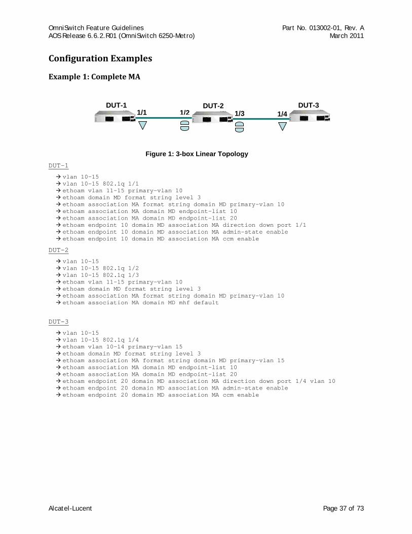
Example 1: Complete MA
1/1 1/41/2 1/3DUT-1 DUT-3 DUT-2
Figure 1: 3-box Linear Topology
DUT-1
vlan 10-15 vlan 10-15 802.1q 1/1 ethoam vlan 11-15 primary-vlan 10 ethoam domain MD format string level 3 ethoam association MA format string domain MD primary-vlan 10 ethoam association MA domain MD endpoint-list 10 ethoam association MA domain MD endpoint-list 20 ethoam endpoint 10 domain MD association MA direction down port 1/1 ethoam endpoint 10 domain MD association MA admin-state enable ethoam endpoint 10 domain MD association MA ccm enable
DUT-2
vlan 10-15 vlan 10-15 802.1q 1/2 vlan 10-15 802.1q 1/3 ethoam vlan 11-15 primary-vlan 10 ethoam domain MD format string level 3 ethoam association MA format string domain MD primary-vlan 10 ethoam association MA domain MD mhf default
DUT-3
vlan 10-15 vlan 10-15 802.1q 1/4 ethoam vlan 10-14 primary-vlan 15 ethoam domain MD format string level 3 ethoam association MA format string domain MD primary-vlan 15 ethoam association MA domain MD endpoint-list 10 ethoam association MA domain MD endpoint-list 20 ethoam endpoint 20 domain MD association MA direction down port 1/4 vlan 10 ethoam endpoint 20 domain MD association MA admin-state enable ethoam endpoint 20 domain MD association MA ccm enable
Alcatel-Lucent Page 37 of 73
OmniSwitch Feature Guidelines Part No. 013002-01, Rev. A AOS Release 6.6.2.R01 (OmniSwitch 6250-Metro) March 2011
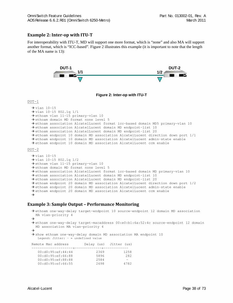
Example 2: Interop with ITUT
For interoperability with ITU-T, MD will support one more format, which is “none” and also MA will support another format, which is “ICC-based”. Figure 2 illustrates this example (it is important to note that the length of the MA name is 13):
1/1 1/2DUT-1 DUT-2
Figure 2: Inter-op with ITU-T
DUT-1
vlan 10-15 vlan 10-15 802.1q 1/1 ethoam vlan 11-15 primary-vlan 10 ethoam domain MD format none level 5 ethoam association AlcatelLucent format icc-based domain MD5 primary-vlan 10 ethoam association AlcatelLucent domain MD endpoint-list 10 ethoam association AlcatelLucent domain MD endpoint-list 20 ethoam endpoint 10 domain MD association AlcatelLucent direction down port 1/1 ethoam endpoint 10 domain MD association AlcatelLucent admin-state enable ethoam endpoint 10 domain MD association AlcatelLucent ccm enable
DUT-2
vlan 10-15 vlan 10-15 802.1q 1/2 ethoam vlan 11-15 primary-vlan 10 ethoam domain MD format none level 5 ethoam association AlcatelLucent format icc-based domain MD primary-vlan 10 ethoam association AlcatelLucent domain MD endpoint-list 10 ethoam association AlcatelLucent domain MD endpoint-list 20 ethoam endpoint 20 domain MD association AlcatelLucent direction down port 1/2 ethoam endpoint 20 domain MD association AlcatelLucent admin-state enable ethoam endpoint 20 domain MD association AlcatelLucent ccm enable
Example 3: Sample Output – Performance Monitoring ethoam one-way-delay target-endpoint 10 source-endpoint 12 domain MD association MA vlan-priority 4
ethoam one-way-delay target-macaddress 00:e0:b1:6a:52:4c source-endpoint 12 domain MD association MA vlan-priority 4
show ethoam one-way-delay domain MD association MA endpoint 10 Legend: Jitter: - = undefined value
Remote Mac address Delay (us) Jitter (us) --------------------+-------------+------------ 00:d0:95:ef:44:44 2369 1258 00:d0:95:ef:66:88 5896 282 00:d0:95:ef:88:88 2584 - 00:d0:95:ef:66:55 2698 4782
Alcatel-Lucent Page 38 of 73
OmniSwitch Feature Guidelines Part No. 013002-01, Rev. A AOS Release 6.6.2.R01 (OmniSwitch 6250-Metro) March 2011
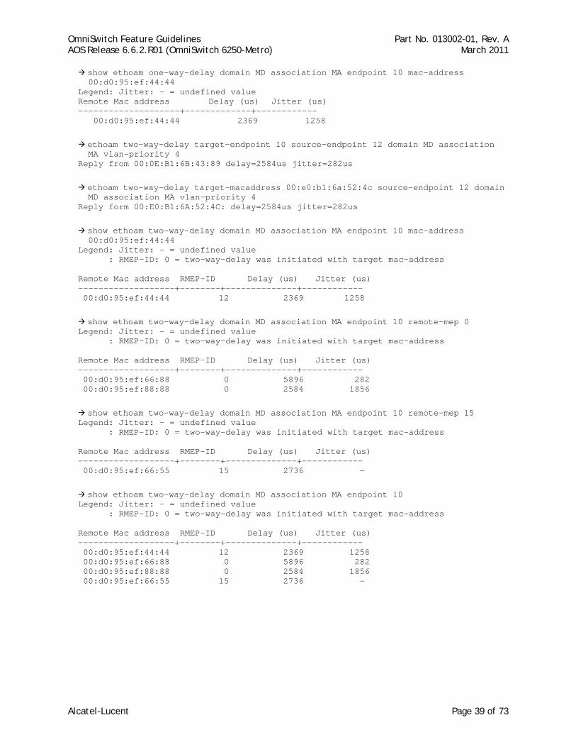
show ethoam one-way-delay domain MD association MA endpoint 10 mac-address 00:d0:95:ef:44:44
Legend: Jitter: - = undefined value Remote Mac address Delay (us) Jitter (us) --------------------+-------------+------------ 00:d0:95:ef:44:44 2369 1258
ethoam two-way-delay target-endpoint 10 source-endpoint 12 domain MD association MA vlan-priority 4
Reply from 00:0E:B1:6B:43:89 delay=2584us jitter=282us
ethoam two-way-delay target-macaddress 00:e0:b1:6a:52:4c source-endpoint 12 domain MD association MA vlan-priority 4
Reply form 00:E0:B1:6A:52:4C: delay=2584us jitter=282us
show ethoam two-way-delay domain MD association MA endpoint 10 mac-address 00:d0:95:ef:44:44
Legend: Jitter: - = undefined value : RMEP-ID: 0 = two-way-delay was initiated with target mac-address Remote Mac address RMEP-ID Delay (us) Jitter (us) -------------------+--------+--------------+------------ 00:d0:95:ef:44:44 12 2369 1258
show ethoam two-way-delay domain MD association MA endpoint 10 remote-mep 0 Legend: Jitter: - = undefined value : RMEP-ID: 0 = two-way-delay was initiated with target mac-address Remote Mac address RMEP-ID Delay (us) Jitter (us) -------------------+--------+--------------+------------ 00:d0:95:ef:66:88 0 5896 282 00:d0:95:ef:88:88 0 2584 1856
show ethoam two-way-delay domain MD association MA endpoint 10 remote-mep 15 Legend: Jitter: - = undefined value : RMEP-ID: 0 = two-way-delay was initiated with target mac-address Remote Mac address RMEP-ID Delay (us) Jitter (us) -------------------+--------+--------------+------------ 00:d0:95:ef:66:55 15 2736 -
show ethoam two-way-delay domain MD association MA endpoint 10 Legend: Jitter: - = undefined value : RMEP-ID: 0 = two-way-delay was initiated with target mac-address Remote Mac address RMEP-ID Delay (us) Jitter (us) -------------------+--------+--------------+------------ 00:d0:95:ef:44:44 12 2369 1258 00:d0:95:ef:66:88 0 5896 282 00:d0:95:ef:88:88 0 2584 1856 00:d0:95:ef:66:55 15 2736 -
Alcatel-Lucent Page 39 of 73
OmniSwitch Feature Guidelines Part No. 013002-01, Rev. A AOS Release 6.6.2.R01 (OmniSwitch 6250-Metro) March 2011
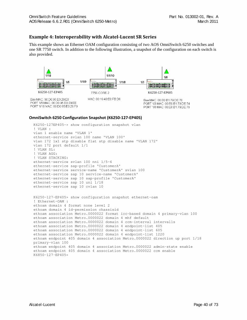
Example 4: Interoperability with AlcatelLucent SR Series
This example shows an Ethernet OAM configuration consisting of two AOS OmniSwitch 6250 switches and one SR 7750 switch. In addition to the following illustration, a snapshot of the configuration on each switch is also provided.
K6250-127-EP405 K6250-127-EP605
OmniSwitch 6250 Configuration Snapshot (K6250‐127‐EP405)
K6250-127EP405-> show configuration snapshot vlan ! VLAN : vlan 1 enable name "VLAN 1" ethernet-service svlan 100 name "VLAN 100" vlan 172 1x1 stp disable flat stp disable name "VLAN 172" vlan 172 port default 1/1 ! VLAN SL: ! VLAN AGG: ! VLAN STACKING: ethernet-service svlan 100 nni 1/5-6 ethernet-service sap-profile "CustomerA" ethernet-service service-name "CustomerA" svlan 100 ethernet-service sap 10 service-name "CustomerA" ethernet-service sap 10 sap-profile "CustomerA" ethernet-service sap 10 uni 1/18 ethernet-service sap 10 cvlan 10
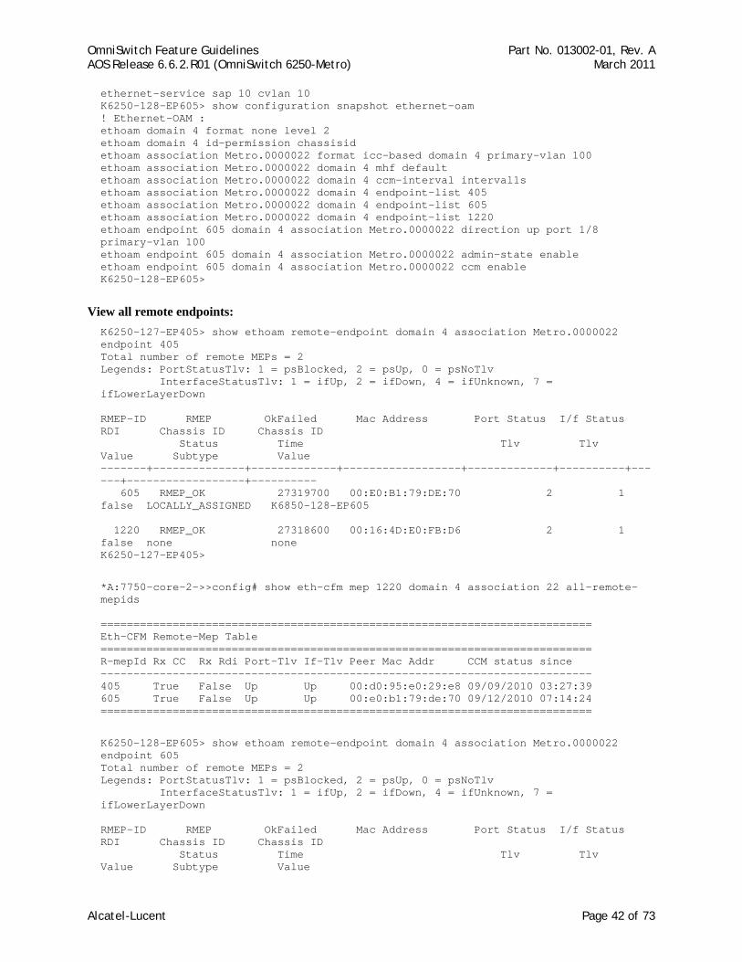
K6250-127-EP405> show configuration snapshot ethernet-oam ! Ethernet-OAM : ethoam domain 4 format none level 2 ethoam domain 4 id-permission chassisid ethoam association Metro.0000022 format icc-based domain 4 primary-vlan 100 ethoam association Metro.0000022 domain 4 mhf default ethoam association Metro.0000022 domain 4 ccm-interval interval1s ethoam association Metro.0000022 domain 4 endpoint-list 405 ethoam association Metro.0000022 domain 4 endpoint-list 605 ethoam association Metro.0000022 domain 4 endpoint-list 1220 ethoam endpoint 405 domain 4 association Metro.0000022 direction up port 1/18 primary-vlan 100 ethoam endpoint 405 domain 4 association Metro.0000022 admin-state enable ethoam endpoint 405 domain 4 association Metro.0000022 ccm enable K6850-127-EP405>
Alcatel-Lucent Page 40 of 73
OmniSwitch Feature Guidelines Part No. 013002-01, Rev. A AOS Release 6.6.2.R01 (OmniSwitch 6250-Metro) March 2011
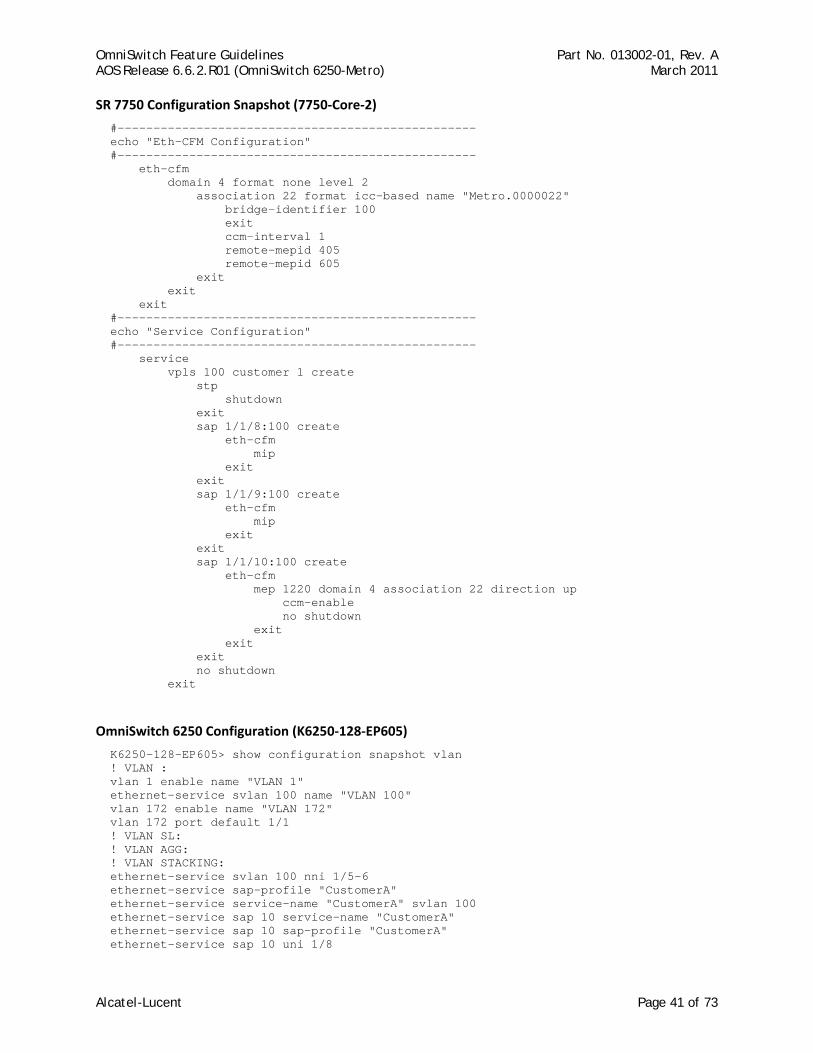
SR 7750 Configuration Snapshot (7750‐Core‐2)
#-------------------------------------------------- echo "Eth-CFM Configuration" #-------------------------------------------------- eth-cfm domain 4 format none level 2 association 22 format icc-based name "Metro.0000022" bridge-identifier 100 exit ccm-interval 1 remote-mepid 405 remote-mepid 605 exit exit exit #-------------------------------------------------- echo "Service Configuration" #-------------------------------------------------- service vpls 100 customer 1 create stp shutdown exit sap 1/1/8:100 create eth-cfm mip exit exit sap 1/1/9:100 create eth-cfm mip exit exit sap 1/1/10:100 create eth-cfm mep 1220 domain 4 association 22 direction up ccm-enable no shutdown exit exit exit no shutdown exit
OmniSwitch 6250 Configuration (K6250‐128‐EP605)
K6250-128-EP605> show configuration snapshot vlan ! VLAN : vlan 1 enable name "VLAN 1" ethernet-service svlan 100 name "VLAN 100" vlan 172 enable name "VLAN 172" vlan 172 port default 1/1 ! VLAN SL: ! VLAN AGG: ! VLAN STACKING: ethernet-service svlan 100 nni 1/5-6 ethernet-service sap-profile "CustomerA" ethernet-service service-name "CustomerA" svlan 100 ethernet-service sap 10 service-name "CustomerA" ethernet-service sap 10 sap-profile "CustomerA" ethernet-service sap 10 uni 1/8
Alcatel-Lucent Page 41 of 73
OmniSwitch Feature Guidelines Part No. 013002-01, Rev. A AOS Release 6.6.2.R01 (OmniSwitch 6250-Metro) March 2011
ethernet-service sap 10 cvlan 10 K6250-128-EP605> show configuration snapshot ethernet-oam ! Ethernet-OAM : ethoam domain 4 format none level 2 ethoam domain 4 id-permission chassisid ethoam association Metro.0000022 format icc-based domain 4 primary-vlan 100 ethoam association Metro.0000022 domain 4 mhf default ethoam association Metro.0000022 domain 4 ccm-interval interval1s ethoam association Metro.0000022 domain 4 endpoint-list 405 ethoam association Metro.0000022 domain 4 endpoint-list 605 ethoam association Metro.0000022 domain 4 endpoint-list 1220 ethoam endpoint 605 domain 4 association Metro.0000022 direction up port 1/8 primary-vlan 100 ethoam endpoint 605 domain 4 association Metro.0000022 admin-state enable ethoam endpoint 605 domain 4 association Metro.0000022 ccm enable K6250-128-EP605>
View all remote endpoints: K6250-127-EP405> show ethoam remote-endpoint domain 4 association Metro.0000022 endpoint 405 Total number of remote MEPs = 2 Legends: PortStatusTlv: 1 = psBlocked, 2 = psUp, 0 = psNoTlv InterfaceStatusTlv: 1 = ifUp, 2 = ifDown, 4 = ifUnknown, 7 = ifLowerLayerDown RMEP-ID RMEP OkFailed Mac Address Port Status I/f Status RDI Chassis ID Chassis ID Status Time Tlv Tlv Value Subtype Value -------+--------------+-------------+------------------+-------------+----------+------+------------------+---------- 605 RMEP_OK 27319700 00:E0:B1:79:DE:70 2 1 false LOCALLY_ASSIGNED K6850-128-EP605 1220 RMEP_OK 27318600 00:16:4D:E0:FB:D6 2 1 false none none K6250-127-EP405>
*A:7750-core-2->>config# show eth-cfm mep 1220 domain 4 association 22 all-remote-mepids =========================================================================== Eth-CFM Remote-Mep Table =========================================================================== R-mepId Rx CC Rx Rdi Port-Tlv If-Tlv Peer Mac Addr CCM status since --------------------------------------------------------------------------- 405 True False Up Up 00:d0:95:e0:29:e8 09/09/2010 03:27:39 605 True False Up Up 00:e0:b1:79:de:70 09/12/2010 07:14:24 ===========================================================================
K6250-128-EP605> show ethoam remote-endpoint domain 4 association Metro.0000022 endpoint 605 Total number of remote MEPs = 2 Legends: PortStatusTlv: 1 = psBlocked, 2 = psUp, 0 = psNoTlv InterfaceStatusTlv: 1 = ifUp, 2 = ifDown, 4 = ifUnknown, 7 = ifLowerLayerDown RMEP-ID RMEP OkFailed Mac Address Port Status I/f Status RDI Chassis ID Chassis ID Status Time Tlv Tlv Value Subtype Value
Alcatel-Lucent Page 42 of 73
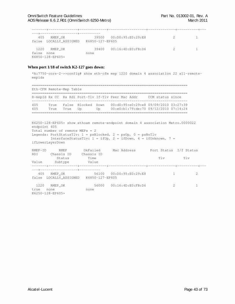
OmniSwitch Feature Guidelines Part No. 013002-01, Rev. A AOS Release 6.6.2.R01 (OmniSwitch 6250-Metro) March 2011
-------+--------------+-------------+------------------+-------------+----------+------+------------------+---------- 405 RMEP_OK 39500 00:D0:95:E0:29:E8 2 1 false LOCALLY_ASSIGNED K6850-127-EP605 1220 RMEP_OK 39400 00:16:4D:E0:FB:D6 2 1 false none none K6850-128-EP605>
When port 1/18 of switch K2-127 goes down: *A:7750-core-2->>config# show eth-cfm mep 1220 domain 4 association 22 all-remote-mepids =========================================================================== Eth-CFM Remote-Mep Table =========================================================================== R-mepId Rx CC Rx Rdi Port-Tlv If-Tlv Peer Mac Addr CCM status since --------------------------------------------------------------------------- 405 True False Blocked Down 00:d0:95:e0:29:e8 09/09/2010 03:27:39 605 True True Up Up 00:e0:b1:79:de:70 09/12/2010 07:14:24 ===========================================================================
K6250-128-EP605> show ethoam remote-endpoint domain 4 association Metro.0000022 endpoint 605 Total number of remote MEPs = 2 Legends: PortStatusTlv: 1 = psBlocked, 2 = psUp, 0 = psNoTlv InterfaceStatusTlv: 1 = ifUp, 2 = ifDown, 4 = ifUnknown, 7 = ifLowerLayerDown RMEP-ID RMEP OkFailed Mac Address Port Status I/f Status RDI Chassis ID Chassis ID Status Time Tlv Tlv Value Subtype Value -------+--------------+-------------+------------------+-------------+----------+------+------------------+---------- 405 RMEP_OK 56100 00:D0:95:E0:29:E8 1 2 false LOCALLY_ASSIGNED K6850-127-EP605 1220 RMEP_OK 56000 00:16:4D:E0:FB:D6 2 1 true none none K6250-128-EP605>
Alcatel-Lucent Page 43 of 73

OmniSwitch Feature Guidelines Part No. 013002-01, Rev. A AOS Release 6.6.2.R01 (OmniSwitch 6250-Metro) March 2011
References • Chapter 34, “Ethernet OAM Commands”, OmniSwitch 6250 CLI Reference Guide (060305-10, Rev. B).
• Chapter 15, “Configuring Ethernet OAM”, OmniSwitch 6250 Network Configuration Guide (060304-10, Rev. B).
Alcatel-Lucent Page 44 of 73
OmniSwitch Feature Guidelines Part No. 013002-01, Rev. A AOS Release 6.6.2.R01 (OmniSwitch 6250-Metro) March 2011
2.11. SAA for ETHOAM Service Assurance Agent (SAA) helps customers to provide service guarantees, increase network reliability by validating network performance, proactively identify network issues, and increase Return on Investment (ROI) by easing the deployment of new services. SAA uses active monitoring to generate traffic in a continuous, reliable, and predictable manner, thus enabling the measurement of network performance and health.
In addition to IP SAA, ETH-LB/DMM can be used to measure delay and jitter by sending out frames with DM information to the peer MEP and receiving frames with DM information from the peer MEP.
Platforms Supported OmniSwitch 6250-Metro Models
Guidelines This section contains configuration guidelines and additional information for the 6.6.2.R01 implementation of SAA for Ethernet OAM.
ETH‐LB/DMM Timeout timer
This timer is started when response message with error code NO_ERROR is received from Ethoam CMM in reply of ETH-LB/DMM initiation request. The timer duration [(numPkts-1)*interPktDelay + 3] seconds (1sec timeout + 2sec to account for the IPC delay from Ethoam NI -> Ethoam CMM -> SAA CMM). If replies are received within this interval, the history statistics are updated; else the iteration is treated as failed.
Session timer
The session timer determines when the next iteration of the SAA will run. This timer is started when an SAA is started (i.e., the first iteration of the SAA is scheduled). For example, if an SAA is scheduled to start at 9:00pm and the current time is 6:00pm, the session timer will start at 9:00pm when the SAA is actually scheduled to start.
The timer value is configurable and measured in minutes. Its default value is 150 minutes.
Response timer
The response timer is started when SAA sends an ETH-LB/DMM initiation request to Ethoam CMM. The value of this timer is one second and specifies the maximum time for which SAA will wait for a reply from ETHOAM.
Scheduling of SAAs
A number of SAAs can be started at once, but only one SAA shall run at any instance of time. Subsequent SAAs shall be run one after the other. The SAA CMM task shall maintain a linked list to schedule the SAAs.
The SAAs shall be scheduled on a first come first serve basis, i.e. the SAA for which start request is received first shall be run first.
When a request to start an SAA is received, a node with the SAA information is inserted in the scheduler linked list. If this is the only node in the list, it is run immediately. If there are already some nodes in the scheduler linked list, then the node for this SAA is inserted at the tail of the linked list.
At the end of each iteration, the corresponding SAA node is removed from the scheduler linked list. If there are nodes remaining in the linked list, the one at the head is run. If there are no more nodes left, no action is taken.
Alcatel-Lucent Page 45 of 73
OmniSwitch Feature Guidelines Part No. 013002-01, Rev. A AOS Release 6.6.2.R01 (OmniSwitch 6250-Metro) March 2011
Delay and Jitter Calculation
An aggregated record is kept for each SAA. This record retains the aggregated information of all the iterations that have been run. The record is updated after nth iteration as follows -
Minimum delay:
Minimum (delayOfIteration1, delayOfIteration2,......, delayOfIterationN)
Average delay:
[(avgDelayIteration1 * pktsRcvdInIteration1)+(avgDelayIteration2 * pktsRcvdInIteration2)+ . . . +(avgDelayIterationN * pktsRcvdInIterationN) ] / (pktsRcvdInIteration1 + pktsRcvdInIteration2 + . . . + pktsRcvdInIterationN)
Maximum delay:
Maximum (delayOfIteration1, delayOfIteration2,......, delayOfIterationN)
Minimum jitter:
Minimum (jitterOfIteration1, jitterOfIteration2,...., jitterOfIterationN)
Average jitter:
[(avgJitterIteration1 * {pktsRcvdInIteration1 – 1}) + (avgJitterIteration2 * {pktsRcvdInIteration2 – 1}) + . . . + (avgJitterIterationN * {pktsRcvdInIterationN–1})] / ({pktsRcvdInIteration1–1}+{pktsRcvdInIteration2–1}+ . . . + {pktsRcvdInIterationN–1})
Maximum jitter:
Maximum (jitterOfIteration1, jitterOfIteration2,...., jitterOfIterationN)
Whenever a new iteration is run, the values are updated as:
Minimum delay:
Minimum (previousDelay, latestIterationDelay)
Average delay:
[ (aggregatedDelay * totalNumPktsRcvd) + (latestIterationDelay * latestNumPktsRcvd) ] / (totalNumPktsRcvd + latestNumPktsRcvd)
Maximum delay:
Maximum (previousDelay, latestIterationDelay)
Minimum jitter:
Minimum (previousJitter, latestIterationJitter)
Average jitter:
[ {aggregatedJitter * (totalJitterSamplesRcvd)} + {latestIterationJitter * (latestNumPktsRcvd - 1)} ] / {( totalJitterSamplesRcvd) + (latestPktsRcvd – 1)}
The totalJitterSamplesRcvd value is a count of the total number of jitter samples received. A jitter sample is obtained when at least two replies are received. For example, five replies received will provide four jitter samples in a single iteration.
Maximum jitter:
Maximum (previousJitter, latestIterationJitter)
For failed iterations, such as iterations in which no reply is received, the delay and jitter statistics are not updated. For iterations in which only one reply is received, only the delay statistics are updated, jitter statistics
Alcatel-Lucent Page 46 of 73
OmniSwitch Feature Guidelines Part No. 013002-01, Rev. A AOS Release 6.6.2.R01 (OmniSwitch 6250-Metro) March 2011
are not updated. In all other cases, for n replies received, n delays and n-1, jitter values are calculated and used for updating statistics.
Other Guidelines
• SAA for ETHOAM - Time-stamping is not available in hardware on all platforms. Therefore, time-stamping is done in software on all platforms.
• The SAA-ETHOAM operations use software based timestamps and hence do not provide precise measurement of network delay.
• Validation of PM family privileges is not supported in 6.4.3.R01 release. Hence, if a user only has bridging configuration privileges, the user is still able to configure SAA for IETH-LB or ETH-DMM.
• The network RTT includes the local software processing time in case the reply is received on a different NI.
• The behavior is undefined in case some SAAs are scheduled and the system time is changed. It is recommended that all the SAAs be rescheduled accordingly.
• Since the SAAs are identified by an alphanumeric name, it is not possible to support a range option in the SAA CLI commands.
• It is not possible to stop a SAA that has not started. Hence, scheduling an SAA to start and stop at a particular time is not possible.
• Advanced statistical measurements are not supported in the 6.6.2.R01 release.
Configuration Examples Creating SAA:
saa saa1 description “saa for ip-ping” saa saa2 description “saa for eth-lb” interval 160 saa saa3 description “saa for eth-dmm” interval 300
Configuring IP/ETH-LB/ETH-DMM SAA:
saa saa1 type ip-ping destination-ip 123.22.45.66 source-ip 123.35.42.125 type-of-service 5 inter-pkt-delay 1500 num-pkts 8 payload-size 1000
saa saa2 type ethoam-loopback target-endpoint 10 source endpoint 2 domain md1 association ma1 vlan-priority 5 drop-eligible true inter-pkt-delay 500
saa saa3 type ethoam-two-way-delay target-endpoint 5 source endpoint 1 domain md2 association ma2 vlan-priority 4 inter-pkt-delay 1000
Starting a SAA:
saa saa1 start saa saa2 start at 2009-10-13,09:00:00.0
Stopping SAA:
saa saa1 stop saa saa2 stop at 2009-10-13,10:00:00.0
Removing SAA:
no saa saa1
Alcatel-Lucent Page 47 of 73

OmniSwitch Feature Guidelines Part No. 013002-01, Rev. A AOS Release 6.6.2.R01 (OmniSwitch 6250-Metro) March 2011
References • Chapter 36, “Service Assurance Agent Commands”, OmniSwitch 6250 CLI Reference Guide (060305-10,
Rev. B).
• Chapter 16, “Service Assurance Agents (SAA)”, OmniSwitch 6250 Network Configuration Guide (060304-10, Rev. B).
Alcatel-Lucent Page 48 of 73
OmniSwitch Feature Guidelines Part No. 013002-01, Rev. A AOS Release 6.6.2.R01 (OmniSwitch 6250-Metro) March 2011
2.12. IP SAA (IPPing) Service Assurance Agent (SAA) helps customers to provide service guarantees, increase network reliability by validating network performance, proactively identify network issues, and increase Return on Investment (ROI) by easing the deployment of new services. SAA uses active monitoring to generate traffic in a continuous, reliable, and predictable manner, thus enabling the measurement of network performance and health.
An IP SAA enhances the service level monitoring to become IP application-aware by measuring both end-to-end and at the IP layer. IP SAA allows performance measurement against any IP addresses in the network (switch, server, pc, etc.).
Platforms Supported OmniSwitch 6250-Metro Models
Guidelines • An IP SAA can be configured between two AOS devices and also between an AOS device and
Linux/Windows. But in this case, delay and jitter measurements may not be accurate as it may not be possible to discount for the software processing time on the peer.
• When the IP SAA is executed, the end-to-end delay and jitter values are captured. The SAA CLI show commands display the minimum, maximum and average values of delay and jitter for each SAA that has been executed.
• The execution result of the SAA is updated as “success” or “failure” based on the statistical values. If the number of received packets is less than 1, the result is updated as “failed”. For example, if 10 ICMP packets are sent and 7 packets are received in reply, the result is “success” and the statistical values are updated. For iterations in which only one reply is received, only the delay statistics are updated, jitter statistics are not updated. Instead, the “–“value is found in the jitter stats output.
• SAA can be scheduled to start and stop at a given time. If a start and stop time are not specified, then the SAA starts executing immediately and keeps running until it is stopped with a stop saa command.
• The following show commands are available to capture SAA execution output:
show saa - displays all the configured SAAs
show saa statistics - displays the statistics of all SAAs
show saa statistics history - displays the statistics history of all SAAs.
show saa statistics aggregate - displays the statistics aggregate of all SAAs.
show saa saa2 statistics history index 1 - displays the statistics of each packet for the iteration number 1
• The SAA IP Ping operation is supported only for IPv4 and not for IPv6.
• The behavior is undefined in the case where some SAAs are scheduled and the system time is changed. It is recommended that all the SAAs be rescheduled accordingly.
• Since the SAAs are identified by an alphanumeric name, it is not possible to support a range option in the SAA CLI commands.
• In a multi-NI scenario, if a reply is received on an NI different from the one that initiated the iteration, the results will not be precise as the CMM timestamp will be used.
• A maximum of 128 SAAs are supported.
Alcatel-Lucent Page 49 of 73
OmniSwitch Feature Guidelines Part No. 013002-01, Rev. A AOS Release 6.6.2.R01 (OmniSwitch 6250-Metro) March 2011
• Since the minimum session interval is 10 minutes, it is recommended that a maximum of 50 SAAs be configured. If the number of SAAs configured is more than 50 and all the SAAs are started together, then the SAAs may not be scheduled exactly after ’session interval’ minutes. The SAAs will be scheduled after all the SAAs that are ahead of it in the scheduler list are completed. If the SAAs are configured with random session interval times (interval values that are not multiples of each other) then more than 50 SAAs may be configured.
• The SAA should not be in a ‘started’ state at the time of modifying num-pkts or inter-pkt-delay. If the SAA is in a ‘started’ state, first stop it and then modify the parameters.
• The source IP and destination IP cannot be a broadcast/multicast address.
• The destination IP cannot be 0.0.0.0.
• The timeout for each ping request packet is 1second. This value is non-configurable.
• A maximum of 5 history records shall be maintained per SAA. This value shall not be configurable.
• A minimum session interval of 10 minutes is supported.
• The SAA iteration is treated as ‘Failed’ only if no replies are received in the iteration.
• If an IP-ping SAA is configured with a source IP address that is not the IP address of a local IP interface or is no longer active on the local switch, then ICMP packets with this source IP are not transmitted on the network.
Configuration Examples The example in this section shows the SAA configuration between source IP 10.10.10.1 and destination IP 20.20.20.1.
• The name of the SAA is db_server with an interval of 10 minutes [the SAA will execute every ten minutes].
• This SAA sends 10 ICMP packets with payload size of 64, inter packet delay of 300 milli seconds and the type of service is configured as 5.
Sample CLI Configuration Commands
saa db_server descr "jitter" interval 10
saa db_server type ip-ping destination-ip 20.20.20.1 source-ip 10.10.10.1 type-of-service 5 num-pkts 10 inter-pkt-delay 300 payload-size 64
Alcatel-Lucent Page 50 of 73
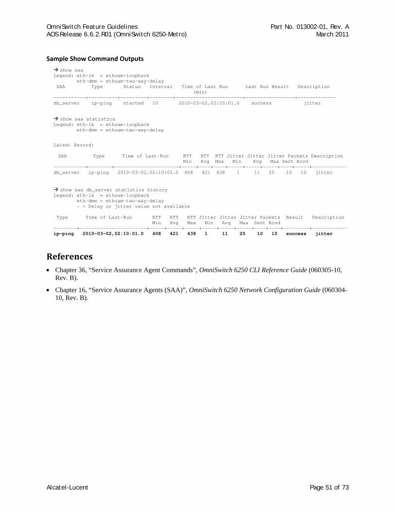
OmniSwitch Feature Guidelines Part No. 013002-01, Rev. A AOS Release 6.6.2.R01 (OmniSwitch 6250-Metro) March 2011
Sample Show Command Outputs
show saa Legend: eth-lb = ethoam-loopback eth-dmm = ethoam-two-way-delay SAA Type Status Interval Time of Last Run Last Run Result Description (min) -----------+----------+---------+--------+-----------------------+-----------------+------------- db_server ip-ping started 10 2010-03-02,02:10:01.0 success jitter
show saa statistics Legend: eth-lb = ethoam-loopback eth-dmm = ethoam-two-way-delay
Latest Record:
SAA Type Time of Last-Run RTT RTT RTT Jitter Jitter Jitter Packets Description Min Avg Max Min Avg Max Sent Rcvd
-----------+--------+----------------------+-----+----+----+-----+-----+-----+----+-----+------------ db_server ip-ping 2010-03-02,02:10:01.0 408 421 438 1 11 25 10 10 jitter
show saa db_server statistics history
Legend: eth-lb = ethoam-loopback eth-dmm = ethoam-two-way-delay - = Delay or jitter value not available Type Time of Last-Run RTT RTT RTT Jitter Jitter Jitter Packets Result Description Min Avg Max Min Avg Max Sent Rcvd --------+-----------------------+-----+-----+-----+-----+-----+-----+----+----+---------+--------ip-ping 2010-03-02,02:10:01.0 408 421 438 1 11 25 10 10 success jitter
----
References • Chapter 36, “Service Assurance Agent Commands”, OmniSwitch 6250 CLI Reference Guide (060305-10,
Rev. B).
• Chapter 16, “Service Assurance Agents (SAA)”, OmniSwitch 6250 Network Configuration Guide (060304-10, Rev. B).
Alcatel-Lucent Page 51 of 73
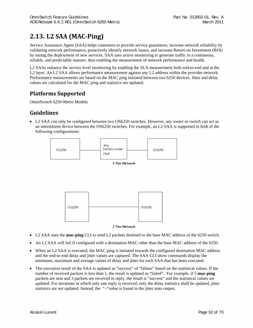
OmniSwitch Feature Guidelines Part No. 013002-01, Rev. A AOS Release 6.6.2.R01 (OmniSwitch 6250-Metro) March 2011
2.13. L2 SAA (MACPing) Service Assurance Agent (SAA) helps customers to provide service guarantees, increase network reliability by validating network performance, proactively identify network issues, and increase Return on Investment (ROI) by easing the deployment of new services. SAA uses active monitoring to generate traffic in a continuous, reliable, and predictable manner, thus enabling the measurement of network performance and health.
L2 SAAs enhance the service level monitoring by enabling the SLA measurement both end-to-end and at the L2 layer. An L2 SAA allows performance measurement against any L2 address within the provider network. Performance measurements are based on the MAC ping initiated between two 6250 devices. Jitter and delay values are calculated for the MAC ping and statistics are updated.
Platforms Supported OmniSwitch 6250-Metro Models
Guidelines • L2 SAA can only be configured between two OS6250 switches. However, any router or switch can act as
an intermittent device between the OS6250 switches. For example, an L2 SAA is supported in both of the following configurations:
• L2 SAA uses the mac-ping CLI to send L2 packets destined to the base MAC address of the 6250 switch.
• An L2 SAA will fail if configured with a destination MAC other than the base MAC address of the 6250.
• When an L2 SAA is executed, the MAC ping is initiated towards the configured destination MAC address and the end-to-end delay and jitter values are captured. The SAA CLI show commands display the minimum, maximum and average values of delay and jitter for each SAA that has been executed.
• The execution result of the SAA is updated as “success” of “failure” based on the statistical values. If the number of received packets is less than 1, the result is updated as “failed”. For example, if 5 mac-ping packets are sent and 3 packets are received in reply, the result is “success” and the statistical values are updated. For iterations in which only one reply is received, only the delay statistics shall be updated, jitter statistics are not updated. Instead, the “–“value is found in the jitter stats output.
Alcatel-Lucent Page 52 of 73

OmniSwitch Feature Guidelines Part No. 013002-01, Rev. A AOS Release 6.6.2.R01 (OmniSwitch 6250-Metro) March 2011
• SAA can be scheduled to start and stop at a given time. If a start and stop time are not specified, then the SAA starts executing immediately and keeps running until it is stopped with a stop saa command.
• The following show commands are available to capture SAA execution output:
show saa - displays all the configured SAAs
show saa statistics - displays the statistics of all SAAs
show saa statistics history - displays the statistics history of all SAAs.
show saa statistics aggregate - displays the statistics aggregate of all SAAs.
show saa saa2 statistics history index 1 - displays the statistics of each packet for the iteration number 1
• The SAA MAC Ping operation uses software based timestamps, therefore precise measurement of network delay is not provided.
• The network RTT includes the local software processing time in case the reply is received on a different NI.
• When an on demand MAC-Ping is in progress, no other SAA-iteration shall run. However, the next MAC-Ping iteration (if any) will begin after the current operation is completed. All SAA related CLI commands will be blocked while MAC-Ping is in progress.
• The behavior is undefined in the case where some SAAs are scheduled and the system time is changed. It is recommended that all the SAAs be rescheduled accordingly.
• Since the SAAs are identified by an alphanumeric name, it is not possible to support a range option in the SAA CLI commands.
• In a multi-NI scenario, if a reply is received on an NI different from the one that initiated the iteration, the results will not be precise as the CMM timestamp will be used.
• A maximum of 128 SAAs are supported.
• Since the minimum session interval is 10 minutes, it is recommended that a maximum of 50 SAAs be configured. If the number of SAAs configured is more than 50 and all the SAAs are started together, then the SAAs may not be scheduled exactly after ’session interval’ minutes. The SAAs will be scheduled after all the SAAs that are ahead of it in the scheduler list are completed. If the SAAs are configured with random session interval times (interval values that are not multiples of each other) then more than 50 SAAs may be configured.
• The SAA should not be in a ‘started’ state at the time of modifying num-pkts or inter-pkt-delay. If the SAA is in a ‘started’ state, first stop it and then modify the parameters.
• The destination MAC address cannot be all 0’s (for a broadcast or multicast address).
• The timeout for each ping request packet is 1second. This value is non-configurable.
• A maximum of 5 history records shall be maintained per SAA. This value shall not be configurable.
• A minimum session interval of 10 minutes is supported.
• The SAA iteration is treated as ‘Failed’ only if no replies are received in the iteration.
Alcatel-Lucent Page 53 of 73
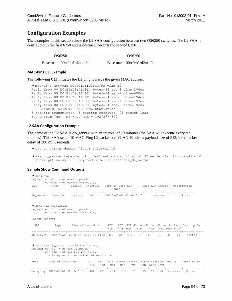
OmniSwitch Feature Guidelines Part No. 013002-01, Rev. A AOS Release 6.6.2.R01 (OmniSwitch 6250-Metro) March 2011
Configuration Examples The examples in this section show the L2 SAA configuration between two OS6250 switches. The L2 SAA is configured in the first 6250 and is destined towards the second 6250.
OS6250 ------------------------------------------- OS6250
Base mac - 00:e0:b1:d2:ae:8e Base mac - 00:e0:b1:d2:ae:9e
MAC‐Ping CLI Example
The following CLI initiates the L2 ping towards the given MAC address: mac-ping dst-mac 00:e0:b1:d2:ae:9e vlan 20
Reply from 00:E0:B1:D2:AE:9E: bytes=64 seq=1 time=204us Reply from 00:E0:B1:D2:AE:9E: bytes=64 seq=2 time=600us Reply from 00:E0:B1:D2:AE:9E: bytes=64 seq=3 time=194us Reply from 00:E0:B1:D2:AE:9E: bytes=64 seq=4 time=197us Reply from 00:E0:B1:D2:AE:9E: bytes=64 seq=5 time=192us ----00:E0:B1:D2:AE:9E MAC-PING Statistics---- 5 packets transmitted, 5 packets received, 0% packet loss round-trip (us) min/avg/max = 192/277/600
L2 SAA Configuration Example
The name of the L2 SAA is db_server with an interval of 10 minutes (the SAA will execute every ten minutes). This SAA sends 10 MAC-Ping L2 packets on VLAN 10 with a payload size of 512, inter packet delay of 300 milli seconds.
saa db_server descry jitter interval 10
saa db_server type mac-ping destination-mac 00:e0:b1:d2:ae:9e vlan 10 num-pkts 10 inter-pkt-delay 300 payload-size 512 data sla_db_server
Sample Show Command Outputs
show saa Legend: eth-lb = ethoam-loopback eth-dmm = ethoam-two-way-delay SAA Type Status Interval Time of Last Run Last Run Result Description (min) -----------+----------+---------+--------+-----------------------+-----------------+------------- db_server mac-ping started 10 2010-07-02,02:10:01.0 success jitter
show saa statistics Legend: eth-lb = ethoam-loopback eth-dmm = ethoam-two-way-delay Latest Record:
SAA Type Time of Last-Run RTT RTT RTT Jitter Jitter Jitter Packets Description Min Avg Max Min Avg Max Sent Rcvd
-----------+--------+----------------------+-----+----+----+-----+-----+-----+----+-----+------------ db_server mac-ping 2010-07-02,02:10:01.0 408 421 438 1 11 25 10 10 jitter
show saa db_server statistics history Legend: eth-lb = ethoam-loopback eth-dmm = ethoam-two-way-delay - = Delay or jitter value not available Type Time of Last-Run RTT RTT RTT Jitter Jitter Jitter Packets Result Description Min Avg Max Min Avg Max Sent Rcvd --------+-----------------------+-----+-----+-----+-----+-----+-----+----+----+---------+------------ mac-ping 2010-07-02,02:10:01.0 408 421 438 1 11 25 10 10 success jitter
Alcatel-Lucent Page 54 of 73

OmniSwitch Feature Guidelines Part No. 013002-01, Rev. A AOS Release 6.6.2.R01 (OmniSwitch 6250-Metro) March 2011
References • Chapter 36, “Service Assurance Agent Commands”, OmniSwitch 6250 CLI Reference Guide (060305-10,
Rev. B).
• Chapter 16, “Service Assurance Agents (SAA)”, OmniSwitch 6250 Network Configuration Guide (060304-10, Rev. B).
Alcatel-Lucent Page 55 of 73

OmniSwitch Feature Guidelines Part No. 013002-01, Rev. A AOS Release 6.6.2.R01 (OmniSwitch 6250-Metro) March 2011
2.14. DHCP Client In the previous AOS implementation, a DHCP Client was only allowed on default VLAN 1 of the switch at boot up time. The 6.6.2.R01 release enhances this capability to support the following functionality:
• The DHCP Client is configurable on any one VLAN, not just the default VLAN. This is done by configuring a DHCP Client IP interface for the designated VLAN.
• The ip interface command now includes a dhcp-client parameter to activate the DHCP Client functionality for the VLAN on which the interface is configured. In addition, new release and renew parameters were added to allow, when necessary, a manual release and renew of the DHCP Client IP address for the switch.
• A permanent DHCP client. The IP lease received by the switch is renewed and rebound according to RFC 2131. The renewal process for a permanent DHCP client keeps the entry active in the DHCP database and provides an indirect way of monitoring the availability of the switch.
• Configurable string for the option-60 field that is sent as part of the DHCP discover/request packets.
• DHCP option-12 support for retrieving the system name.
When the switch receives a valid IP address lease from a DHCP server:
• The IP address and the subnet mask (DHCP option 1) are assigned to the DHCP Client IP interface.
• A default static route is created according to DHCP option 3 (Router IP Address).
• The lease is periodically renewed and rebound according to the renew time (DHCP option 58) and rebind time (DHCP option 59) returned by the DHCP Server. If the lease cannot be renewed within the lease time (DHCP option 51) returned by the DHCP Server, the lease will be released. When not specified by the DHCP Server, a default lease time of 7 days is allocated.
• The system name is set according to the hostname (DHCP option 12) returned by the DHCP Server. This applies only when the default system name has not been changed. Once set by DHCP option 12, the system name can be saved in the boot.cfg, but will not change the running configuration status. Setting the system name in this manner is mainly used for the initial DHCP cycle, when the switch boots with no configured system name. Note that when an IP lease is released, the system name is not modified.
Platforms Supported OmniSwitch 6250-Metro Models
Guidelines • Previous commands for configuring a DHCP Client on the switch (ip helper boot-up and ip helper boot-
up enable) have been deprecated and replaced with the ip interface dhcp-client command. However, the switch will accept a configuration file that contains the deprecated commands and will enable the DHCP client on the VLAN 1 interface. Upon the next write memory, the old CLI command will be replaced with the new ip interface dhcp-client command.
• In the previous implementation of this feature, the IP interface does not age out even after the IP address lease time expires. However, with the 6.6.2.R01 version, the DHCP Client will initiate the IP address lease extension period and update the IP address if there is any change. If the DHCP Client is not able to renew or get an IP address after the DHCP server assigned lease time expires, the switch will remove the default static route and will render the DHCP client interface inactive. At this point, a DHCP renew is required to start the DHCP client process again.
• The DHCP Client-enabled IP address serves as the primary IP address when multiple addresses are configured for a VLAN.
Alcatel-Lucent Page 56 of 73
OmniSwitch Feature Guidelines Part No. 013002-01, Rev. A AOS Release 6.6.2.R01 (OmniSwitch 6250-Metro) March 2011
• Make sure the DHCP server is reachable through the DHCP Client VLAN.
• Setting the DHCP Server address lease time to 5 minutes is recommended.
• When a DHCP release is performed or the DHCP client interface is deleted, any default static route added for the client is also removed and the corresponding timers (such as release/renew timer) are cancelled. However, the system name will remain unchanged even if the name was updated using the DHCP client option-12 information.
• The previous implementation of this feature sent DHCP discover packets only from the first available slot. However, in the 6.6.2.R01 release, UDP relay will send DHCP packets on all available NIs. DHCP discover packets are flooded on all the ports that are members of the DHCP Client-enabled VLAN.
Reload and Takeover (dhcpClient.db file)
The following information is stored in the dhcpClient.db file located in the /flash/switch directory on the switch:
• DHCP server assigned IP
• VLAN information
• Subnet mask
• Router IP address
• Checksum value (validates the integrity of the file).
The dhcpClient.db file is used during a switch reload or CMM takeover. The IP address saved in this file is the address requested from the DHCP server in the event of a reload or takeover. The checksum value is used to validate the integrity of the file.
Whenever there is any change in the DHCP server assigned IP address, the dhcpClient.db file is updated with the new information and synchronized to the secondary CMM. This file is also synchronized at a periodic time interval of 5 minutes along with the DHCP snooping binding table. This synchronization shall not affect the switch synchronization status.
During takeover the new CMM shall use the dhcpClient.db file and try to acquire the same IP address again. The DHCP client shall try to send the BootP packets only after the NI is back up. For example, after a takeover:
• The DHCP client interface uses the dhcpClient.db file information to create the IP interface with a lease time of 10 minutes and try to acquire the same IP address.
• After successful renewal of the IP address, the lease time is modified as per the DHCP server assigned IP address.
• If the DHCP client is not able acquire the same IP address, the client will then try to get a new IP address after the switch-assigned DHCP lease time expires. Note that a trap message is sent whenever there is any change to the IP address.
Other Guidelines
• The IP address of a DHCP-Client interface is not configurable; this address is assigned through the DHCP Client process of requesting an IP address.
• DHCP Client only supports IPv4 addresses.
• When using this feature in a stack configuration, enable MAC Retention to ensure that the same IP address is obtained from the DHCP server after takeover.
Alcatel-Lucent Page 57 of 73
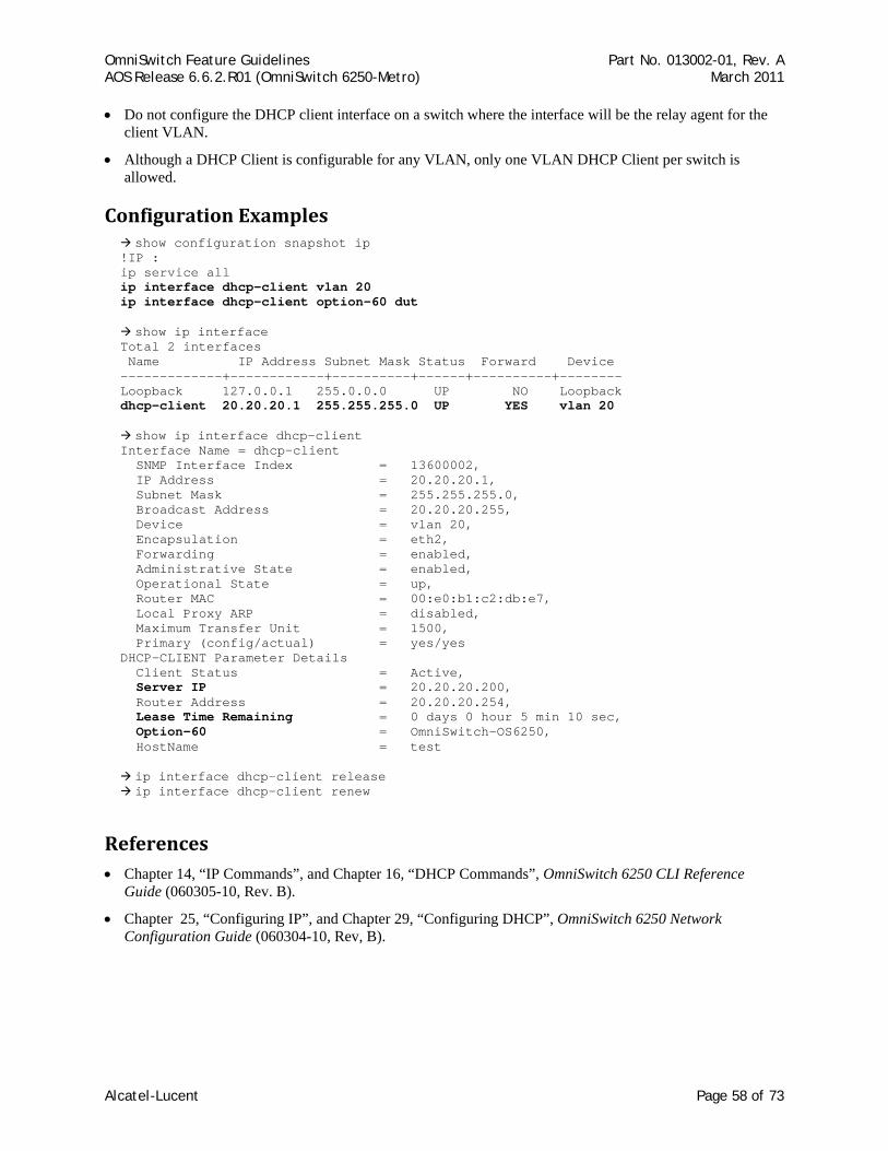
OmniSwitch Feature Guidelines Part No. 013002-01, Rev. A AOS Release 6.6.2.R01 (OmniSwitch 6250-Metro) March 2011
• Do not configure the DHCP client interface on a switch where the interface will be the relay agent for the client VLAN.
• Although a DHCP Client is configurable for any VLAN, only one VLAN DHCP Client per switch is allowed.
Configuration Examples show configuration snapshot ip
!IP : ip service all ip interface dhcp-client vlan 20 ip interface dhcp-client option-60 dut
show ip interface Total 2 interfaces Name IP Address Subnet Mask Status Forward Device -------------+------------+----------+------+----------+-------- Loopback 127.0.0.1 255.0.0.0 UP NO Loopback dhcp-client 20.20.20.1 255.255.255.0 UP YES vlan 20
show ip interface dhcp-client Interface Name = dhcp-client SNMP Interface Index = 13600002, IP Address = 20.20.20.1, Subnet Mask = 255.255.255.0, Broadcast Address = 20.20.20.255, Device = vlan 20, Encapsulation = eth2, Forwarding = enabled, Administrative State = enabled, Operational State = up, Router MAC = 00:e0:b1:c2:db:e7, Local Proxy ARP = disabled, Maximum Transfer Unit = 1500, Primary (config/actual) = yes/yes DHCP-CLIENT Parameter Details Client Status = Active, Server IP = 20.20.20.200, Router Address = 20.20.20.254, Lease Time Remaining = 0 days 0 hour 5 min 10 sec, Option-60 = OmniSwitch-OS6250, HostName = test
ip interface dhcp-client release ip interface dhcp-client renew
References • Chapter 14, “IP Commands”, and Chapter 16, “DHCP Commands”, OmniSwitch 6250 CLI Reference
Guide (060305-10, Rev. B).
• Chapter 25, “Configuring IP”, and Chapter 29, “Configuring DHCP”, OmniSwitch 6250 Network Configuration Guide (060304-10, Rev, B).
Alcatel-Lucent Page 58 of 73
OmniSwitch Feature Guidelines Part No. 013002-01, Rev. A AOS Release 6.6.2.R01 (OmniSwitch 6250-Metro) March 2011
2.15. OutoftheBox AutoConfiguration The Out-of-the-Box Auto-Configuration (automatic remote configuration download) capability automates and simplifies the deployment of large network installations eliminating the need for manual configuration of each device. It also ensures that each device is compliant with the centrally controlled device configuration policies and firmware revisions.
This feature is exclusive to the OmniSwitch and provides the ability to automate the following tasks for a newly deployed switch:
• OmniSwitch firmware upgrades.
• Configuration of a switch on bootup when the switch is first connected to the network.
• Download and installation of critical configuration bootup and image files.
These tasks are automated through the use of an instruction file. This file provides the necessary information a newly deployed OmniSwitch requires to download any necessary firmware upgrades or obtain a switch configuration without user intervention.
The auto-configuration download process automatically invokes the following actions necessary for a switch to gain network connectivity and access to the instruction file:
1. Configuration of a DHCP Client interface for VLAN 1 (or a learned management VLAN ID) when the switch initially boots up.
2. Obtain an IP lease (IP address, mask, default gateway, and system name), the address of a TFTP file server, and the name of the instruction file from a reachable DHCP server.
3. Download the instruction file, which contains the information to obtain the configuration file, image files and/or script files from the given TFTP, FTP or SCP servers.
4. Download and apply the image and configuration file.
5. Reboot the switch with the upgraded image files and switch configuration file, or if no images or boot configuration is downloaded, scripted instructions are executed on the fly and the switch is made available remotely.
Platforms Supported OmniSwitch 6250-Metro Models
Guidelines
New Default Switch Behavior
The 6.6.2 implementation of the Out-of-the-Box Auto-Configuration resulted in the following changes to the default switch behavior:
• Newly deployed or upgraded switches with no boot.cfg file running AOS 6.6.2 will automatically run the Out of the Box Auto-Configuration feature. This causes the OK LED to blink amber while the process is running. If the Auto-Configuration process is not successful the OK LED will continue to blink amber as long as no boot.cfg file is on the switch, this is normal behavior in 6.6.2.
• Once the Auto-Configuration process times out (approximately 30 seconds) the switch configuration can be saved to the boot.cfg file using the write memory command. The OK LED will then turn solid green as in previous releases.
Alcatel-Lucent Page 59 of 73
OmniSwitch Feature Guidelines Part No. 013002-01, Rev. A AOS Release 6.6.2.R01 (OmniSwitch 6250-Metro) March 2011
• Additionally, the Auto-Configuration feature will automatically create a DHCP client IP interface on VLAN 1. This interface can be deleted using the no ip interface dhcp-client command if desired.
Automatic Configuration Download Process
The automatic configuration download process is triggered when the following occurs:
• There is no boot.cfg file found in the Working directory of the switch or during a takeover or reboot on the new Primary unit or CMM.
• The initialization process of the switch is complete and the network interfaces or ports are ready.
• There is connectivity with a DHCP server and a TFTP file server. This connectivity is mandatory.
Learned Management VLAN
An OmniSwitch running the Auto-Configuration feature is automatically enabled to process LLDP PDUs that contain the Nearest-Edge destination MAC address (01:20: DA: 02:01:73). This specific type of LLDP PDU is generated from a management switch when the Nearest-Edge mode is enabled for that switch.
The Auto-Configuration feature looks for these unique PDUs to obtain a management VLAN ID. If such a VLAN ID is made available, the Auto-Configuration feature will create a DHCP client interface and tag DHCP request packets with the provided VLAN.
By default, VLAN 1 is used if a management VLAN is not detected. The Auto-Configuration feature is useful when a DHCP client interface is needed on a VLAN other than the default VLAN.
Although the management switch uses LLDP to generate LLDP packets addressed to a unique multicast address, installing LLDP on intermediate switches across the network is not required.
Network Components
The following network components are required to support Out-of-the-Box Auto-Configuration:
• DHCP server. Any DHCP server can be used; this requirement is not based on a specific vendor. Using a Class C IP address pool is highly recommended; using Class B will consume a high amount of switch memory. For more information, see the DHCP Server Configuration Example.
• Network gateway or router. The switch must be able to reach the gateway that the DHCP server will provide to the switch. Depending on the topology, specific gateway configuration is required. This could be either UDP relay or VLAN configuration.
• TFTP file server. A reachable TFTP server is required to transfer the instruction file to the switch. Firmware and configuration files may also reside on this server.
• Primary FTP/SFTP server. Based on the instruction file, this server stores a certain number of files required to be transferred to the switch, such as firmware, configuration files, debug files, and a script file.
• Secondary FTP/SFTP server (optional). In case the primary FTP/TFTP server fails or the files are not available, auto remote config tries to download the files from the secondary server.
• Management Switch. Required only if the Nearest-Edge mode is used to advertise a specific management VLAN ID on which the Auto-Configuration feature will configure a DHCP client.
Alcatel-Lucent Page 60 of 73
OmniSwitch Feature Guidelines Part No. 013002-01, Rev. A AOS Release 6.6.2.R01 (OmniSwitch 6250-Metro) March 2011
Download Files
The following types of files are used during the auto-configuration process:
Instruction file
This file is the initial file required for the automatic-configuration process to occur. The instruction file is stored in the TFTP server with the .alu extension and provides the names and location of servers and download files needed to complete the auto-configuration process.
When the switch obtains the instruction file, it compares the firmware version in the file with the version that is running on the switch. If both versions are the same, the firmware download is skipped. If the versions are different, the switch downloads the image files from the location provided in the instruction file.
This feature is able to distinguish the image files required for different platforms. Therefore, image files for different switch platforms can reside in the same firmware location.
For more information, see the Instruction File Example.
Firmware upgrade files
Firmware (image) files differ depending on the OmniSwitch platform. These files contain executable code, which provides support for the system, Ethernet ports, and network functions.
Configuration file
The configuration file (boot.cfg) is stored in the FTP/SFTP server. The auto-configuration process downloads this file from the server and reboots the switch. The configuration file is then applied to the switch after boot up. Any error in the configuration file will be reflected in the .err file in /flash. In the instruction file, the configuration file may have any name, but when the file is transferred to the switch, it will be placed in the /flash/working directory with the boot.cfg name.
Debug Configuration file
During the auto-configuration process, the debug configuration file is downloaded with the filename AlcatelDebug.cfg. The debug file is accessed to check the errors that occur during download process. All errors that occur during the automatic remote configuration download process are displayed on the switch command prompt and also stored in the switch log (swlog.log file). The switch is automatically rebooted when new firmware or configuration file has been downloaded or if the script file contains a reload command. However, if the debug file is the only file to be downloaded, then the switch is not automatically rebooted.
Script file
The script file is downloaded and stored with the same name in the /flash/working directory. During the auto-configuration process:
• The script file is downloaded and implemented.
• The DHCP client configured on VLAN 1 is removed.
• The commands in the script file are run on the switch in the order specified.
Alcatel-Lucent Page 61 of 73
OmniSwitch Feature Guidelines Part No. 013002-01, Rev. A AOS Release 6.6.2.R01 (OmniSwitch 6250-Metro) March 2011
The script file contains the commands to be implemented on the switch after the configuration file, if available, is applied, or the script file can be used to configure the switch dynamically without a boot.cfg file. The following provides an example of a script file:
vlan 100 enable name "VLAN 100" vlan 100 port default 1/1 write memory reload working no rollback-timeout
The main purpose of script file is to configure a set of switches. In addition, the script file can have commands that are not desired in the configuration file, such as write memory and reload working no rollback-timeout. The auto-configuration process confirms that such command actions are completed.
Consider the following guidelines when using script files:
• A write memory command issued by a script file will override the boot.cfg file that was downloaded from the FTP/SFTP server. Therefore, make sure that a script file with such command is not downloaded along with a boot.cfg file.
• After the script file is downloaded, the auto-configuration process will not automatically reload the switch unless such a command exists in the script file.
• If both write memory and reload working no rollback-timeout are in the script file, after bootup, the switch will have only the configuration based on the script file contents.
• If write memory does not exist in the script file, only reload working no rollback-timeout, the switch state after bootup depends on whether or not the boot.cfg file was downloaded.
• If downloading the boot.cfg file was included in the instruction file, then the switch comes back up with the configuration file based on the boot.cfg file. However, if no boot.cfg file was downloaded or exists in /flash/working, when the switch comes back up the auto-configuration process will be initiated.
Manual Configuration
In the event auto-configuration fails and user-intervention is needed, the procedure for manual download and installation of component files is as follows:
1. Download the required files, which are present on the FTP/SFTP servers, or directly transfer files to the OmniSwitch using Zmodem.
2. Download the image files for firmware upgrade.
3. When the boot.cfg file is downloaded individually, the auto-configuration process takes over and initiates a reload working no rollback-timeout.
4. If a script file is downloaded along with the boot.cfg file, then the auto-configuration process runs the commands in the script file.
5. If required, perform a write memory and reload working no-rollback timeout command on the switch to install all the downloaded files and reload the switch.
Configuration Examples This section provides the following configuration examples:
• Auto-Configuration Network Components
• Learned Management VLAN Configuration
• DHCP Client Configuration (includes additional guidelines)
• Instruction File Configuration (includes additional guidelines)
Alcatel-Lucent Page 62 of 73
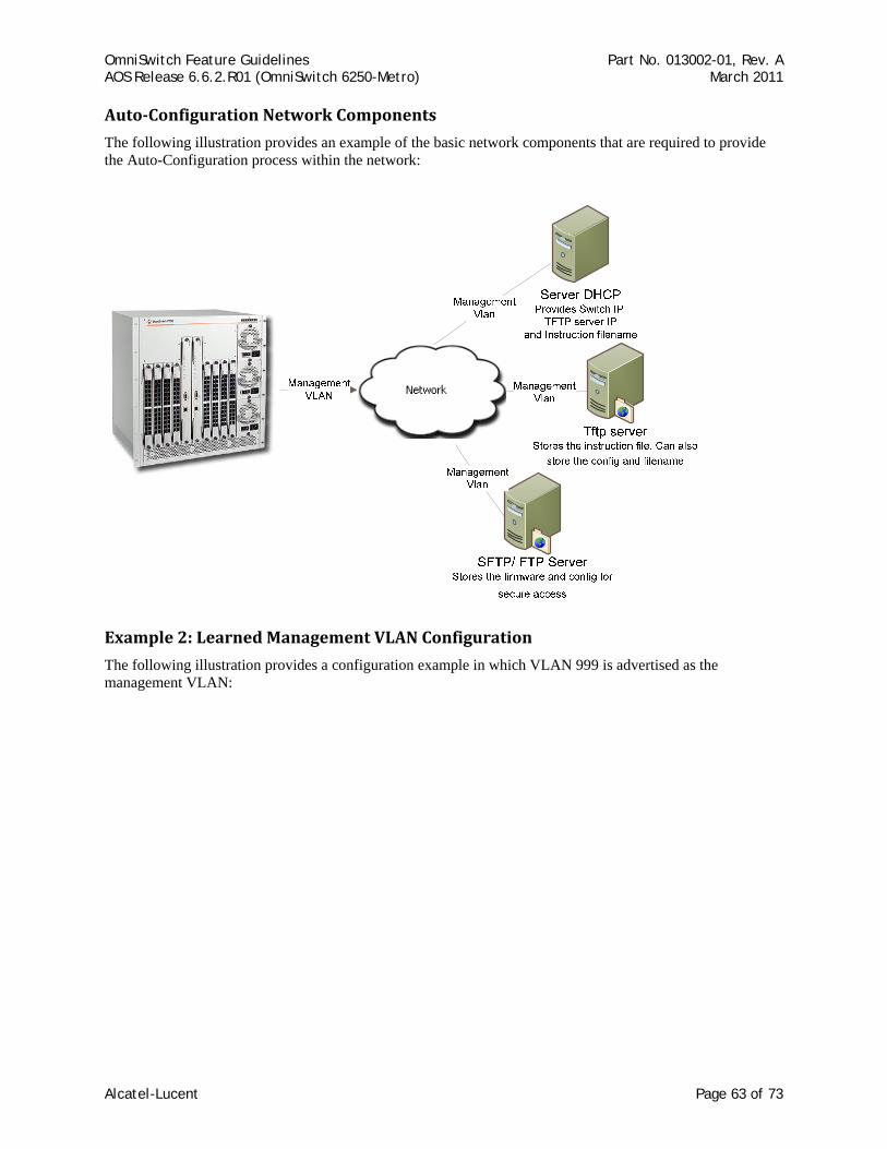
OmniSwitch Feature Guidelines Part No. 013002-01, Rev. A AOS Release 6.6.2.R01 (OmniSwitch 6250-Metro) March 2011
AutoConfiguration Network Components
The following illustration provides an example of the basic network components that are required to provide the Auto-Configuration process within the network:
Example 2: Learned Management VLAN Configuration
The following illustration provides a configuration example in which VLAN 999 is advertised as the management VLAN:
Alcatel-Lucent Page 63 of 73
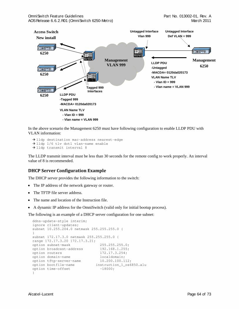
OmniSwitch Feature Guidelines Part No. 013002-01, Rev. A AOS Release 6.6.2.R01 (OmniSwitch 6250-Metro) March 2011
6250
Management VLAN 999
Management 6250
6250
6250
Access Switch New install
Untagged Interface Vlan 999
Tagged 999 Interfaces
Untagged Interface Def VLAN = 999
LLDP PDU -Untagged -MACDA= 0120da020173 VLAN Name TLV - Vlan ID = 999 - Vlan name = VLAN 999
LLDP PDU -Tagged 999 -MACDA= 0120da020173
VLAN Name TLV - Vlan ID = 999 - Vlan name = VLAN 999
In the above scenario the Management 6250 must have following configuration to enable LLDP PDU with VLAN information:
lldp destination mac-address nearest-edge lldp 1/6 tlv dot1 vlan-name enable lldp transmit interval 8
The LLDP transmit interval must be less than 30 seconds for the remote config to work properly. An interval value of 8 is recommended.
DHCP Server Configuration Example
The DHCP server provides the following information to the switch:
• The IP address of the network gateway or router.
• The TFTP file server address.
• The name and location of the Instruction file.
• A dynamic IP address for the OmniSwitch (valid only for initial bootup process).
The following is an example of a DHCP server configuration for one subnet: ddns-update-style interim; ignore client-updates; subnet 10.255.204.0 netmask 255.255.255.0 { } subnet 172.17.3.0 netmask 255.255.255.0 { range 172.17.3.20 172.17.3.21; option subnet-mask 255.255.255.0; option broadcast-address 192.168.1.255; option routers 172.17.3.254; option domain-name localdomain; option tftp-server-name 10.200.100.112; option bootfile-name instruction_1_os6850.alu option time-offset -18000; }
Alcatel-Lucent Page 64 of 73
OmniSwitch Feature Guidelines Part No. 013002-01, Rev. A AOS Release 6.6.2.R01 (OmniSwitch 6250-Metro) March 2011
Instruction File Example
The instruction file provides the following information:
• Firmware version and file location.
• Configuration file name and location.
• Debug configuration file name and location.
• Script file name and location.
• Primary FTP/SFTP file server address / type / username.
• Secondary FTP/SFTP file server address / type / username.
The following is an example of an instruction file: ! Alcatel-Lucent OmniSwitch OS6850 – Instruction file version 1.2.1 ! Firmware version Firmware version:OS_6_4_3_355_R01 Firmware location:/home/ftpboot/firmware ! Configuration file Config filename:boot_OS6850.cfg Config location:/home/ftpboot/config ! Debug file Debug filename:AlcatelDebug.cfg Debug location:/home/ftpboot/debug ! Script file Script filename:OS6850_script.txt ! Primary File Server Primary server:10.200.100.112 Primary protocol:FTP Primary user:admin ! Secondary File Server Secondary server:10.200.110.111 Secondary protocol:SFTP Secondary user:admin
Consider the following guidelines when configuring the instruction file:
• The instruction file is case sensitive and can contain only the keywords provided in the example above.
• The keywords can be placed in any order.
• If the keyword:value format is incorrect, the information on that line is discarded.
• The firmware version must be provided in the format as specified in the example.
• The pathnames provided must contain the complete path to the file location. Maximum length of the pathname is 255 characters, filename is 63 characters.
• If any file is not required, enter “None” for the keyword value. For example, if a debug configuration file download is not required, the following instruction file syntax is used: Debug filename:None Debug location:None
• The header line is the first line of the instruction file and begins with “!” character. Header line contents are logged to the switch log along with the other contents of the instruction file.
• The “!” character is also used to designate a comment line or to disable an option line. The header and comment lines begin with “!” character.
Alcatel-Lucent Page 65 of 73
OmniSwitch Feature Guidelines Part No. 013002-01, Rev. A AOS Release 6.6.2.R01 (OmniSwitch 6250-Metro) March 2011
• For the FTP/TFTP server entries, the username and password are the same. The username should not exceed 16 characters. This is a limitation for the server, not the OmniSwitch.
• The instruction file must have the .alu extension. The instruction file is not downloaded if it does not include the .alu extension.
• If an error or failure occurs during the file transfer, the transfer process is retried up to 3 times.
• If file transfer and download fails, the automatic remote configuration process is stopped. This condition requires user intervention.
• All contents of the instruction file are stored in the switch log (swlog.log) file as evidence of the last auto-configuration download.
References Chapter 8, “Managing Automatic Remote Configuration Download”, OmniSwitch 6250 Switch Management Guide (060306-10, Rev. A).
Alcatel-Lucent Page 66 of 73

OmniSwitch Feature Guidelines Part No. 013002-01, Rev. A AOS Release 6.6.2.R01 (OmniSwitch 6250-Metro) March 2011
2.16. Dying Gasp One of the most critical problems in an access network for carriers is differentiating between a simple power failure at the customer premise and an equipment or facility failure. Dying gasp provides this information by having a node indicate to the network that it is having a power failure.
This feature is designed to send a message on power loss (main or backup power supply). There are two types of messages sent:
SNMP Trap
As soon as the power failure is detected, a SNMP trap message is sent to the first two configured SNMP stations. The trap includes the following information:
• Slot number
• Power supply type (primary/backup)
• Time of the failure
Link OAM PDU
As soon as the power failure is detected, an 802.3ah OAM Information PDU is sent to all ports of the NI for which link OAM is enabled. The PDU will have the Dying Gasp bit set.
Platforms Supported OmniSwitch 6250-Metro Models
Guidelines • The following scenarios will trigger a Dying Gasp event:
The main power supply fails (if it is the only power supply present).
The backup power supply fails first and then the main power supply goes down.
The main power supply fails first and then the backup power supply goes down.
A reload command is issued.
A takeover command is issued.
• As soon as the Dying Gasp event is detected, an 802.3ah OAM Information PDU is sent to all ports on which Link OAM is enabled. The PDU will have the Dying Gasp bit set. The Dying Gasp packets are first sent on high priority ports followed by least priority ports. Uplink ports are treated as high priority ports followed by combo ports and user ports.
• The Link-OAM application sends Dying Gasp packets to high priority ports followed by low priority ports on which Link-OAM is enabled.
• The current design of this feature does not handle the scenario where both the main and backup power supplies are on and both power supplies go down simultaneously. This is because the detection of the power status using the polling task will take time to determine the failure of both power supplies. In a customer setup, however, it is recommended that each power supply should take power from a different source to avoid simultaneous power failures.
• SNMP trap polling runs every one minute, so if a change is made to the interface on which the trap is sent and a power failure occurs within the next one minute polling interval, the Dying Gasp trap will not be sent to the SNMP station. This is because the source MAC/IP and destination MAC (next hop MAC)
Alcatel-Lucent Page 67 of 73
OmniSwitch Feature Guidelines Part No. 013002-01, Rev. A AOS Release 6.6.2.R01 (OmniSwitch 6250-Metro) March 2011
information has not yet been entered into the MAC and IP header due to the polling timer not yet updating this information.
• The Dying Gasp event can only be sent to an IPv4, SNMPv2 station.
• The Link-OAM application may not send Dying Gasp packets to a peer if Link-OAM is enabled on all ports. Because Link-OAM Dying Gasp packets are sent on a port priority basis, there may not be enough time to send on all ports if Link-OAM is enabled on all 28 ports.
Configuration Example
SNMP TRAP OUTPUT 02:50:17 Trap Received from 10.135.59.4: sysUpTime="0" snmpTrapOID="esmDrvTrapDropsLink.3" alaDyingGaspSlot="1" alaDyingGaspPowerSupplyType="primary" alaDyingGaspTime="TUE APR 03 06:58:21 2001" 03:50:17 Trap Received from 10.135.59.4: sysUpTime="0" snmpTrapOID="esmDrvTrapDropsLink.3" alaDyingGaspSlot="1" alaDyingGaspPowerSupplyType="backup" alaDyingGaspTime="TUE APR 03 03:58:21 2001"
References Chapter 2, “OmniSwitch 6250 Series Chassis and Hardware Components”, OmniSwitch 6250 Series Hardware Users Guide (060303-10, Rev. B).
Alcatel-Lucent Page 68 of 73

OmniSwitch Feature Guidelines Part No. 013002-01, Rev. A AOS Release 6.6.2.R01 (OmniSwitch 6250-Metro) March 2011
3. Existing Feature Guidelines This section contains information and guidelines for the following OmniSwitch features that were introduced or enhanced in a previous release:
• Spanning Tree
• General L3 Routing
Alcatel-Lucent Page 69 of 73
OmniSwitch Feature Guidelines Part No. 013002-01, Rev. A AOS Release 6.6.2.R01 (OmniSwitch 6250-Metro) March 2011
3.1. Spanning Tree The Alcatel-Lucent Spanning Tree implementation provides support for the Q2005 version of MSTP, the 802.1w Rapid Spanning Tree Algorithm and Protocol (RSTP) and the 802.1D Spanning Tree Algorithm and Protocol (STP). All three supported protocols ensure that there is always only one data path between any two switches for a given Spanning Tree instance to prevent network loops.
Q2005 (MSTP) is only available when the flat mode is active for the switch. The flat mode applies a single spanning tree instance across all VLAN port connections on a switch. MSTP allows the configuration of Multiple Spanning Tree Instances (MSTIs) in addition to the CST instance. Each MSTI is mapped to a set of VLANs. As a result, flat mode can support the forwarding of VLAN traffic over separate data paths.
802.1D STP and 802.1w RSTP are available in both the flat and 1x1 mode. However, when using 802.1D or 802.1w in the flat mode, the single spanning tree instance per switch algorithm applies.
Platforms Supported OmniSwitch 6250
Guidelines • Maximum Number of STP Instances:
Flat Mode: STP/RSTP – 1 Instance, MSTP – 1 CIST and 16 MST Instances
1x1 Mode: STP/RSTP –256 Instances
• Root bridge priority / path cost
• RSTP (802.1w) is the default Spanning Tree protocol for the switch regardless of which mode is active.
• The bridge priority can be any value between 0 and 65535 for STP and RSTP in the 16-bit mode. By default, Spanning Tree follows the 16-bit path cost.
• The bridge priority can only be in multiples of 4096 in the 32-bit mode or in MSTP mode.
• MSTP can support 32 bit-mode per standard.
• Changing the STP protocol to MSTP will reset all priority and path cost of a bridge to the default values.
• Up to 128 Link Aggregates are supported with a maximum of 256 aggregated ports.
• The default port path costs for IEEE Std 802.1D-1998- 16 Bit are:
Port Speed Path cost 10M 100 100M 19 1000 M 4 10000 M 3
Alcatel-Lucent Page 70 of 73
OmniSwitch Feature Guidelines Part No. 013002-01, Rev. A AOS Release 6.6.2.R01 (OmniSwitch 6250-Metro) March 2011
• The default port path costs are for IEEE Std. 802.1Q-2005 32 Bit are:
Port Speed Path cost 10M 2000000 100M 200000 1000 M 20000 10000 M 2000
• The default link aggregation path costs for 16 Bit are:
Linkagg speed Linkagg size Path cost
10M
2 60 4 40 8 30
100M
2 12 4 9 8 7
1000M N/A 3 10000M N/A 2
• The default link aggregation path costs for 32 Bit are:
LinkAgg speed LinkAgg size Path cost
10M
2 1200000 4 800000 8 600000
100M
2 120000 4 80000 8 60000
1000M 2 12000 4 8000 8 6000
10000M 2 1200 4 800 8 600
The path cost depends on the configured LinkAgg size and not on the active port size.
Alcatel-Lucent Page 71 of 73

OmniSwitch Feature Guidelines Part No. 013002-01, Rev. A AOS Release 6.6.2.R01 (OmniSwitch 6250-Metro) March 2011
References • Chapter 7, “Distributed Spanning Tree Commands”, OmniSwitch 6250 CLI Reference Guide (060305-10,
Rev. B).
• Chapter 10, “Using 802.1Q 2005 Multiple Spanning Tree”, and Chapter 11, “Configuring Spanning Tree Parameters”, OmniSwitch 6250 Network Configuration Guide (060304-10, Rev. B).
Alcatel-Lucent Page 72 of 73
OmniSwitch Feature Guidelines Part No. 013002-01, Rev. A AOS Release 6.6.2.R01 (OmniSwitch 6250-Metro) March 2011
Alcatel-Lucent Page 73 of 73
3.2. General L3 Routing This section provides general guidelines related to L3 routing.
Platforms Supported OmniSwitch 6250
Guidelines
RIP
• Only the Dynamic Unicast routing protocols, RIP and RIPng, are supported.
• RIP specifications:
Maximum of 10 interfaces
Maximum of 10 RIP peers
Maximum of 256 RIP routes
Maximum of 256 ECMP entries
Maximum of 4 next hops per ECMP entry
• RIPng specifications:
Maximum of 10 interfaces
Maximum of 10 RIP peers
Maximum of 128 RIP routes
Maximum of 128 ECMP entries
Maximum of 4 next hops per ECMP entry
Static Routing
• Up to 256 IPv4 Static routes and 128 IPv4 interfaces supported.
• Up to 128 IPv6 Static routes and 16 IPv6 interfaces supported.
Multicast Switching
• Maximum of 1024 IPv4 multicast groups supported
• Maximum of 512 IPv6 multicast groups supported.
• Up to 2K packets/second IGMP traffic rate supported.
• Up to 512 packets/second IPMS data traffic rate supported.
• The multicast IPMS/MLD unknown flood feature is not supported.
References Chapter 25, “Configuring IP”, Chapter 26 “Configuring IPv6”, Chapter 27 “Configuring RIP”, OmniSwitch 6250 Network Configuration Guide (060304-10, Rev. B).