
OmniSwitch 8800 Getting Started Guide 8800 Getting Star… · March 2005 OmniSwitch 8800 1...
72
OmniSwitch ® 8800 Getting Started Guide 060182-10, Rev. D March 2005
-
Upload
truongkhanh -
Category
Documents
-
view
277 -
download
2
Transcript of OmniSwitch 8800 Getting Started Guide 8800 Getting Star… · March 2005 OmniSwitch 8800 1...

OmniSwitch® 8800Getting Started Guide
060182-10, Rev. DMarch 2005

Alcatel Internetworking26801 West Agoura Road
Calabasas, CA 91301(818) 880-3500 FAX (818) 880-3505
US Customer Support: (800) 995-2696International Customer Support: (818) 878-4507
Internet: http://eservice.ind.alcatel.com
Warning. Only personnel knowledgeable in basic electrical and mechanical procedures should install or maintain this equipment.
Lithium Batteries Caution. There is a danger of explosion if the Lithium battery in your chassis is incorrectly replaced. Replace the battery only with the same or equivalent type of battery recommended by the manufacturer. Dispose of used batteries according to the manufacturer’s instructions. The manufacturer’s instructions are as follows:
The features and specifications described in this guide are subject to change without notice.
Copyright © 2005 by Alcatel Internetworking, Inc. All rights reserved. This document may not be reproduced in whole or in part without the express written permission of Alcatel Internetworking, Inc.
Alcatel® and the Alcatel logo are registered trademarks of Alcatel. Xylan®, OmniSwitch®, OmniStack®, and Alcatel OmniVista® are registered trademarks of Alcatel Internetworking, Inc.
OmniAccess™, Omni Switch/Router™, PolicyView™, RouterView™, SwitchManager™, VoiceView™, WebView™, X-Cell™, X-Vision™, and the Xylan logo are trademarks of Alcatel Internetworking, Inc.
This OmniSwitch product contains components which may be covered by one or more of the following U.S. Patents: • U.S. Patent No. 6,339,830 • U.S. Patent No. 6,070,243 • U.S. Patent No. 6,061,368 • U.S. Patent No. 5,394,402• U.S. Patent No. 6,047,024• U.S. Patent No. 6,314,106• U.S. Patent No. 6,542,507
Return the module with the Lithium battery to Alcatel. The Lithium battery will be replaced at Alcatel’s factory.
March 2005 iii
OmniSwitcFeatures
HardAvai
Installing tItems ReSite Prep
EnviElecWeig
Items IncUnpackin
UnpRC
LiftiMou
InstaUsinGrou
Interface (NI) and odules (CMMs) . . . . . .13
. . . . . . . . . . . . . . . . . . . .13 . . . . . . . . . . . . . . . . . . . .13onnectors . . . . . . . . . . .16ules . . . . . . . . . . . . . . . .17 . . . . . . . . . . . . . . . . . . . .18 . . . . . . . . . . . . . . . . . . . .19
ling . . . . . . . . . . . . . 20e Console/Modem . . . . . . . . . . . . . . . . . . . .20Default Settings . . . . . .20nts . . . . . . . . . . . . . . . . .21
. . . . . . . . . . . . . . . . . . . . 22 . . . . . . . . . . . . . . . . . . . .22
ion . . . . . . . . . . . . . . . 23. . . . . . . . . . . . . . . . . . . . 23tion for the EMP . . . . . 24. . . . . . . . . . . . . . . . . . . . 25sion Types . . . . . . . . . . .25ed Session Types . . . . . .25s are allowed? . . . . . . . .26ord . . . . . . . . . . . . . . . . 26one . . . . . . . . . . . . . . . . 27
Table
h 8800 . . . . . . . . . . . . . . . . . . . . . . . . 1. . . . . . . . . . . . . . . . . . . . . . . . . . . . . . . . . . . 1ware Features . . . . . . . . . . . . . . . . . . . . . . . 1lability Features . . . . . . . . . . . . . . . . . . . . . . 2
he Hardware . . . . . . . . . . . . . . . 3quired . . . . . . . . . . . . . . . . . . . . . . . . . . . . . 3aration . . . . . . . . . . . . . . . . . . . . . . . . . . . . 3ronmental Requirements . . . . . . . . . . . . . . . 3trical Requirements . . . . . . . . . . . . . . . . . . . 3ht Considerations . . . . . . . . . . . . . . . . . . . . 4luded . . . . . . . . . . . . . . . . . . . . . . . . . . . . . 4g and Installing the Switch . . . . . . . . . . . . 5
acking the Chassis . . . . . . . . . . . . . . . . . . . . 5ecommendations . . . . . . . . . . . . . . . . . . . . 5hassis Removal Instructions . . . . . . . . . . . 5
Power Supply Removal Instructions . . . . . . 6ng the Chassis . . . . . . . . . . . . . . . . . . . . . . . 7nting the Switch . . . . . . . . . . . . . . . . . . . . . 7Airflow Considerations . . . . . . . . . . . . . . . . 7Module Access Considerations . . . . . . . . . . 8Rack-Mounting . . . . . . . . . . . . . . . . . . . . . . 8Stand-Alone . . . . . . . . . . . . . . . . . . . . . . . . 10lling Power Supplies . . . . . . . . . . . . . . . . . 10g the Grounding Wrist Strap and Chassis nding Lug . . . . . . . . . . . . . . . . . . . . . . . . . 12
Installing the NetworkChassis Management M
NI Modules . . . . .CMMs . . . . . . . . .
Installing MiniGBIC CInstalling Xenpak ModInstalling SFMs . . . . .Blank Cover Plates . .
Connections and CabSerial Connection to th Port . . . . . . . . . . . . . .
Serial Connection EMP Cable Requireme
Booting the Switch . . Component LEDs . . .
Your First Login SessLogging In to the Switch . Setting IP Address InformaUnlocking Session Types
Unlocking All SesUnlocking SpecifiHow many session
Changing the Login PasswSetting the System Time Z
of Contents
iv March 2005
C
. . . . . . . . . . . . . . . . . . . 38 . . . . . . . . . . . . . . . . . . . 38 . . . . . . . . . . . . . . . . . . . 38 . . . . . . . . . . . . . . . . . . . 38 . . . . . . . . . . . . . . . . . . . 39ies . . . . . . . . . . . . . . . . 40 . . . . . . . . . . . . . . . . . . .40 . . . . . . . . . . . . . . . . . . .40h directory the switch is
. . . . . . . . . . . . . . . . . . . .41 to the Certified. . . . . . . . . . . . . . . . . . . .41n the switch boots? . . . .41fied Are Identical . . . . .41fied Are Different . . . . .42ertified directories arece a reboot from the? . . . . . . . . . . . . . . . . . .42
. . . . . . . . . . . . . . . . . . . 43ions . . . . . . . . . . . . . . . 43 . . . . . . . . . . . . . . . . . . . 44
. . . . . . . . . . . . . . . . . . . 46 . . . . . . . . . . . . . . . . . . . 46 . . . . . . . . . . . . . . . . . . . 46 . . . . . . . . . . . . . . . . . . . 47 . . . . . . . . . . . . . . . . . . . 47 . . . . . . . . . . . . . . . . . . . 49 . . . . . . . . . . . . . . . . . . . 49
Setting the Date and Time . . . . . . . . . . . . . . . . . . . 27Setting Optional System Information . . . . . . . . . . . . . . . . . . . . . . . . . . . . . . . 28
Specifying an Administrative Contact . . . . . . . 28Specifying a System Name . . . . . . . . . . . . . . . . 28Specifying the Switch’s Location . . . . . . . . . . . 28
Viewing Your Changes . . . . . . . . . . . . . . . . . . . . . 29Saving Your Changes . . . . . . . . . . . . . . . . . . . . . . . 29Modifying the Serial Connection Settings . . . . . . . 29
LI Basics . . . . . . . . . . . . . . . . . . . . . . . . . . . . . . . . . . 31CLI Assistance Features . . . . . . . . . . . . . . . . . . . . . 31
Syntax Checking . . . . . . . . . . . . . . . . . . . . . . . . 31Command Line (?) Help . . . . . . . . . . . . . . . . . . 32Partial Keyword Completion . . . . . . . . . . . . . . 32Deleting Characters . . . . . . . . . . . . . . . . . . . . . 32Inserting Characters . . . . . . . . . . . . . . . . . . . . . 33Previous Command Recall . . . . . . . . . . . . . . . . 33Prefix Recognition . . . . . . . . . . . . . . . . . . . . . . 33Prefix Prompt . . . . . . . . . . . . . . . . . . . . . . . . . . 34Command History . . . . . . . . . . . . . . . . . . . . . . . 34Command Logging . . . . . . . . . . . . . . . . . . . . . . 35
Enabling Command Logging . . . . . . . . . . . 35Common CLI Commands . . . . . . . . . . . . . . . . . . . . 36
Offline Configuring . . . . . . . . . . . . . . . . . . . . . . . . . . . . 37Syntax Checking . . . . . . . . . . . . . . . . . . . . . . . . 37Scheduling a Configuration File to be Applied at a Later Time . . . . . . . . . . . . . . . . . . . . . . . . . 37
Generating Snapshots of the Current Configuration . . . . . . . . . . . . . . . . . . . . . . 37
Files and Directories .Boot and Image Files . . . . . . . .
boot.params File . . . . . . . .boot.cfg File . . . . . . . . . . .Image Files . . . . . . . . . . . .
Working and Certified DirectorWorking DirectoryCertified DirectoryHow can I tell whiccurrently using? . Can I save changes directory? . . . . . . What happens wheWorking and CertiWorking and CertiMy Working and C different. Can I for Working directory
Loading Software . . . .Non-Redundant ConfiguratRedundant Configurations
Using WebView . . . . . . .Browser Compatibility . . .Required Image Files . . . .Logging In to WebView . .Navigating WebView . . . .Online Help . . . . . . . . . . . .Additional Information . . .
Ma v
H
nel . . . . . . . . . . . . . . . . 63
on CD . . . . . . . . . . . 64. . . . . . . . . . . . . . . . . . . . 65
rch 2005
Troubleshooting . . . . . . . . . . . . . . . . . . . . . . . . . . . 49The WebView login screen does not display. . . . . . . . . . . . . . . . . . . . . . . . . . . . 49The login screen displays, but my login attempt fails. . . . . . . . . . . . . . . . . . . . . . . . 49
ardware Basics . . . . . . . . . . . . . . . . . . . . . . . . 50Chassis Slot Numbering . . . . . . . . . . . . . . . . . . . . . 50
Chassis Management Module (CMM) . . . . . . . . . . . . . 51CMM Redundancy . . . . . . . . . . . . . . . . . . . . . . . . . 52CMM Slot Locations . . . . . . . . . . . . . . . . . . . . . . . 52
CMM Front Panel . . . . . . . . . . . . . . . . . . . . . . . 53Switch Fabric Module (SFM) . . . . . . . . . . . . . . . . . . . . 54
SFM Redundancy . . . . . . . . . . . . . . . . . . . . . . . . . . 54SFM Slot Locations . . . . . . . . . . . . . . . . . . . . . . . . 54
SFM Front Panel . . . . . . . . . . . . . . . . . . . . . . . . 55Network Interface (NI) Modules . . . . . . . . . . . . . . . . . . 56
ENI Modules . . . . . . . . . . . . . . . . . . . . . . . . . . . . . 56GNI Modules . . . . . . . . . . . . . . . . . . . . . . . . . . . . . 56
Miniature Gigabit Interface Converters (MiniGBICs) . . . . . . . . . . . . . . . . . . . . . . . . . . . 56
10GNI Modules . . . . . . . . . . . . . . . . . . . . . . . . . . . 57Xenpaks . . . . . . . . . . . . . . . . . . . . . . . . . . . . . . 57
OS8-ENI-C24 Front Panel . . . . . . . . . . . . . . . . . . . 58OS8-GNI-U8 Front Panel . . . . . . . . . . . . . . . . . . . . 59OS8-GNI-C8 Front Panel . . . . . . . . . . . . . . . . . . . . 60OS8-GNI-U24 Front Panel . . . . . . . . . . . . . . . . . . 61OS8-GNI-C24 Front Panel . . . . . . . . . . . . . . . . . . . 62
OS8-10GNI-UR1 Front Pa
User Documentation General Information . . . .

vi March 2005

Marc OmniSwitch 8800 1
O
Fea
Alca10/10embe
Both10/10Giga
Har
The OmediOmnto 38ports
The Ocomp
•
•
•
•
•
•
8800
h 2005
mniSwitch 8800
tures
tel’s OmniSwitch 8800 switches offer high performance 0 Ethernet and Gigabit Ethernet capabilities, as well as dded server load balancing for enterprise requirements.
half-duplex and full-duplex modes are supported on all 0 Ethernet ports; full-duplex mode is supported on
bit Ethernet and 10 Gigabit Ethernet ports.
dware Features
mniSwitch 8800 is an 18-slot switch designed for the um enterprise core or large wiring closet. The iSwitch 8800 offers up to 384 10/100 Ethernet ports, up 4 Gigabit Ethernet ports, or up to 16 10 Gigabit Ethernet for use as a core switch.
mniSwitch 8800 chassis contains the following major onents:
16 Network Interface (NI) module slots
Two Chassis Management Module (CMM) slots
Five Switch Fabric Module (SFM) slots
Two chassis (front) fan trays
One fabric (rear) fan tray
Power supply slot holding up to four power supplies
OmniSwitch
OS
-GN
I-C8
ACT
LINK
ACT
LINK
ACT
LINK
ACT
LINK
ACT
LINK
ACT
LINK
ACT
LINK
ACT
LINK
OK1
OK2
1
2
3
4
5
6
7
8
OS
-GN
I-C8
ACT
LINK
ACT
LINK
ACT
LINK
ACT
LINK
ACT
LINK
ACT
LINK
ACT
LINK
ACT
LINK
OK1
OK2
1
2
3
4
5
6
7
8
OS
-GN
I-C8
ACT
LINK
ACT
LINK
ACT
LINK
ACT
LINK
ACT
LINK
ACT
LINK
ACT
LINK
ACT
LINK
OK1
OK2
1
2
3
4
5
6
7
8
OS
-GN
I-C8
ACT
LINK
ACT
LINK
ACT
LINK
ACT
LINK
ACT
LINK
ACT
LINK
ACT
LINK
ACT
LINK
OK1
OK2
1
2
3
4
5
6
7
8
OS
8800-C
MM
OK1
OK2
PRI
SEC
TEMP
FAN
STATUS
CONSOLE/ MODEM
1
2
3
ACT
LINK
ENET
OS
-GN
I-U8
LINK
ACT
LINK
ACT
LINK
ACT
LINK
ACT
LINK
ACT
LINK
ACT
LINK
ACT
LINK
ACT 8
7
6
5
4
3
2
1
OK1
OK2
OS
-GN
I-U8
LINK
ACT
LINK
ACT
LINK
ACT
LINK
ACT
LINK
ACT
LINK
ACT
LINK
ACT
LINK
ACT 8
7
6
5
4
3
2
1
OK1
OK2
OS
-GN
I-U8
LINK
ACT
LINK
ACT
LINK
ACT
LINK
ACT
LINK
ACT
LINK
ACT
LINK
ACT
LINK
ACT 8
7
6
5
4
3
2
1
OK1
OK2
OS
-GN
I-U8
LINK
ACT
LINK
ACT
LINK
ACT
LINK
ACT
LINK
ACT
LINK
ACT
LINK
ACT
LINK
ACT 8
7
6
5
4
3
2
1
OK1
OK2
OS
-EN
I-C24
1
2
12
14
3
5
7
9
11
13
15
17
19
21
23
OK1
OK2
24
OS
-EN
I-C24
1
2
12
14
3
5
7
9
11
13
15
17
19
21
23
OK1
OK2
24
OS
-EN
I-C24
1
2
12
14
3
5
7
9
11
13
15
17
19
21
23
OK1
OK2
24
OS
-EN
I-C24
1
2
12
14
3
5
7
9
11
13
15
17
19
21
23
OK1
OK2
24
OS
8800-C
MM
OK1
OK2
PRI
SEC
TEMP
FAN
STATUS
CONSOLE/ MODEM
1
2
3
ACT
LINK
ENET
OS
-EN
I-C24
1
2
12
14
3
5
7
9
11
13
15
17
19
21
23
OK1
OK2
24
OS
-EN
I-C24
1
2
12
14
3
5
7
9
11
13
15
17
19
21
23
OK1
OK2
24
OS
-EN
I-C24
1
2
12
14
3
5
7
9
11
13
15
17
19
21
23
OK1
OK2
24
OS
-EN
I-C24
1
2
12
14
3
5
7
9
11
13
15
17
19
21
23
OK1
OK2
24

2 March 2005
Av
Avtioabhaswinc
FoOm77Om
OmniSwitch 8800
ailability Features
ailability ensures that your switch is consistently opera-nal for your day-to-day networking needs. This added reli-ility is provided through redundant components for critical rdware and software subsystems. OmniSwitch 8800 itches provide a broad variety of availability features, luding:
• Software Redundancy • Hardware Redundancy• Configuration Redundancy• Link Redundancy • Smart Continuous Switching• NI Module Forwarding During CMM Failover• Image Rollback• Hot Swapping• Hardware Monitoring• Power Checking Sequencer more information on Availability features, refer to the niSwitch 8800 Hardware Users Guide, the OmniSwitch
00/7800/8800 Switch Management Guide, and the niSwitch 7700/7800/8800 Network Configuration Guide.
Ma Installing the Hardware 3
It
Si
En
Oman
e following general electri-
ounded AC outlet for each stalled in the chassis. offer both AC and DC to the OmniSwitch 8800 ore information.
er connections, each meters (approximately tension cords.
niSwitch 8800 power r cords connected to 220 use 110 Volt power cords
ible, it is recommended separate circuit. With t fails, the switch’s remain- circuits) will likely be ntinue operating.
I
rch 2005
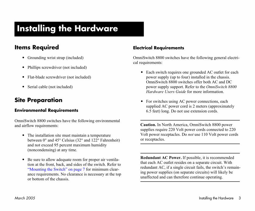
ems Required
• Grounding wrist strap (included)
• Phillips screwdriver (not included)
• Flat-blade screwdriver (not included)
• Serial cable (not included)
te Preparation
vironmental Requirements
niSwitch 8800 switches have the following environmental d airflow requirements:
• The installation site must maintain a temperature between 0° and 45° Celsius (32° and 122° Fahrenheit) and not exceed 95 percent maximum humidity (noncondensing) at any time.
• Be sure to allow adequate room for proper air ventila-tion at the front, back, and sides of the switch. Refer to “Mounting the Switch” on page 7 for minimum clear-ance requirements. No clearance is necessary at the top or bottom of the chassis.
Electrical Requirements
OmniSwitch 8800 switches have thcal requirements:
• Each switch requires one grpower supply (up to four) inOmniSwitch 8800 switches power supply support. ReferHardware Users Guide for m
• For switches using AC powsupplied AC power cord is 26.5 feet) long. Do not use ex
Caution. In North America, Omsupplies require 220 Volt poweVolt power receptacles. Do notor receptacles.
Redundant AC Power. If possthat each AC outlet resides on aredundant AC, if a single circuiing power supplies (on separateunaffected and can therefore co
nstalling the Hardware
4 March 2005
W
WmoOm
It
Yo
Getting Started Guide
ng the following manuals:
tarted Guide
Users Guide
Guide
0 Switch Management
0 Network
0 Advanced Routing
Installing the Hardware
eight Considerations
hen fully-populated (i.e., with all CMM, SFM, and NI dules, fan trays and power supplies installed), the niSwitch 8800 weighs approximately 220 lbs (100 Kgs).
ems Included
ur OmniSwitch 8800 order includes the following items:
• OmniSwitch chassis with factory-installed power supplies per order
• CMM module(s) per order
• Factory-installed SFM modules per order
• NI modules per order
• MiniGBICs per order, if applicable
• Xenpaks per order, if applicable
• Blank cover panels, if applicable
• Grounding wrist strap
• Power cord(s) per order, if applicable
• Hardcopy OmniSwitch 8800
• Documentation CD containi
OmniSwitch 8800 Getting S
OmniSwitch 8800 Hardware
OmniSwitch CLI Reference
OmniSwitch 7700/7800/880Guide
OmniSwitch 7700/7800/880Configuration Guide
OmniSwitch 7700/7800/880Configuration Guide
Ma Installing the Hardware 5
U
Un
Todisrec
Re
Ch
the chassis with the white
ell of the packaging. Lift slides free from the rest of access to the chassis.
ting brackets for 19-inch
page 8 for more informa-ting brackets.
tive plastic from the switch
t of the chassis, it is all factory-installed power the packaging.
Removal Instructions” on
lies to power supplies that chassis. They have no /off switches are in the off n removing power ting in an existing switch, Hardware Users Guide.
rch 2005
npacking and Installing the Switch
packing the Chassis
protect your switch components from electrostatic charge (ESD) and physical damage, read all unpacking ommendations and instructions carefully before beginning.
commendations
• Unpack your OmniSwitch chassis as close as possible to the location where it will be installed.
• Network Interface (NI) modules and Chassis Manage-ment Modules (CMMs) are packaged in separate boxes. In order to greatly reduce exposure to electro-static discharge (ESD) and physical damage, do not unpack these boxes until the CMMs and NI modules are ready to be installed.
assis Removal Instructions
1 Begin by carefully cutting the tape along the seam marked “OPEN HERE FIRST.”
2 Lift the box’s top flaps. Remove the smaller boxes that are enclosed and set them aside. These smaller boxes contain the Ship Kit.
3 Next, completely remove the four white plastic inserts (two on the front and two on the back) from the sides of the box. Removing these inserts allows the overpack to be removed.
Caution. Do not attempt to lift plastic inserts.
4 The overpack is the outer shthe overpack straight up until itthe packaging. This allows easy
5 Remove the two rack-mounracks.
Note. See “Rack-Mounting” ontion on installing the rack-moun
6 Carefully remove the protecchassis.
7 In order to reduce the weighrecommended that you remove supplies prior to lifting it from
8 Continue to “Power Supply page 6.
Note. The subsection below appare newly-shipped in the switchpower cords attached and the on( O ) position. For instructions osupplies that are currently operarefer to your OmniSwitch 8800
6 March 2005
Po ndle at the front of the e power supply out of the he power supply ne hand.
ulled out far enough (about d under the power supply
supply out until it is
n a clean, static-free tall it later.
r supplies by repeating
ssis” on page 7.
OK1OK2
50/60Hz, 8.0 A
230V
CAUTION: THIS UNIT MAY BE EQUIPPED
WITH FOUR POW
ER SUPPLIE CORDS. TO RED
THE RISK OF ELECTRICAL SHOCK, DISCONNE
ALL POWER SUPPLY CORDS BEFORE
SERVICING UNIT.
Installing the Hardware
wer Supply Removal Instructions
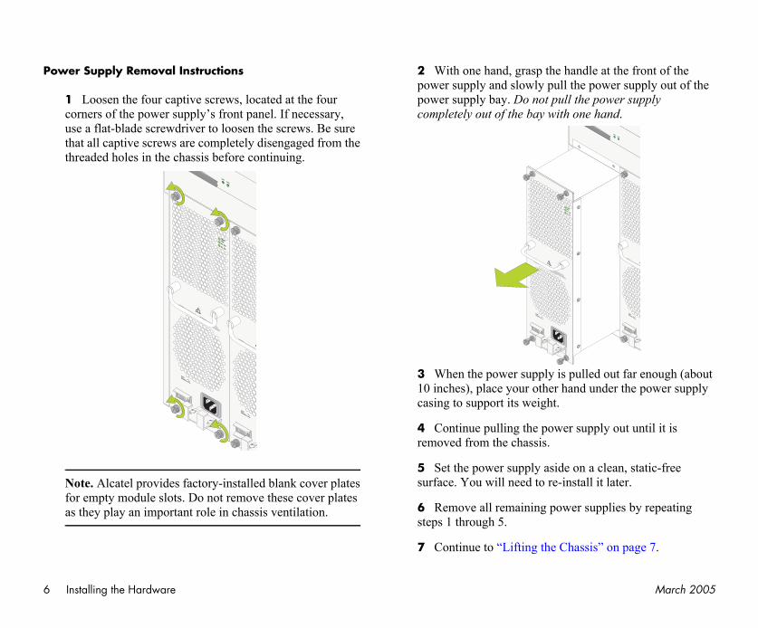
1 Loosen the four captive screws, located at the four corners of the power supply’s front panel. If necessary, use a flat-blade screwdriver to loosen the screws. Be sure that all captive screws are completely disengaged from the threaded holes in the chassis before continuing.
Note. Alcatel provides factory-installed blank cover plates for empty module slots. Do not remove these cover plates as they play an important role in chassis ventilation.
2 With one hand, grasp the hapower supply and slowly pull thpower supply bay. Do not pull tcompletely out of the bay with o
3 When the power supply is p10 inches), place your other hancasing to support its weight.
4 Continue pulling the power removed from the chassis.
5 Set the power supply aside osurface. You will need to re-ins
6 Remove all remaining powesteps 1 through 5.
7 Continue to “Lifting the Cha
50/60Hz, 8.0 A
230V
AC OK
DC OK
TEMPFAIL
!
CAUTION: THIS UNIT MAY BE EQUIPPED
WITH FOUR POW
ER SUPPLIE CORDS. TO REDUCE
THE RISK OF ELECTRICAL SHOCK, DISCONNECT
ALL POWER SUPPLY CORDS BEFORE
SERVICING UNIT.
ATTENTION: CET APPAREIL COMPORTE
PLUS D'UN CORDON D'ALIMENTATION. AFIN DE
PREVENIR LES CHOCS ELECTRIQUES, DEBRANCHE
TOUS LES CORDONS D'ALIMENTATION AVANTE DE
FAIRE LA REPARATION.
50/60Hz, 8.0 A
230V
CAUTION: THIS UNIT MAY BE EQUIPPED
WITH FOUR POW
ER SUPPLIE CORDS. TO RED
THE RISK OF ELECTRICAL SHOCK, DISCONNE
ALL POWER SUPPLY CORDS BEFORE
SERVICING UNIT.
OK1OK2
50/60Hz, 8.0 A
230V
AC OK
DC OK
TEMPFAIL
!
CAUTION: THIS UNIT MAY BE EQUIPPED
WITH FOUR POW
ER SUPPLIE CORDS. TO REDUCE
THE RISK OF ELECTRICAL SHOCK, DISCONNECT
ALL POWER SUPPLY CORDS BEFORE
SERVICING UNIT.
ATTENTION: CET APPAREIL COMPORTE
PLUS D'UN CORDON D'ALIMENTATION. AFIN DE
PREVENIR LES CHOCS ELECTRIQUES, DEBRANCHE
TOUS LES CORDONS D'ALIMENTATION AVANTE DE
FAIRE LA REPARATION.
Ma Installing the Hardware 7
Lif
Onsuanim
Co
ss, and airflow require-hes cannot be wall-
a well-ventilated, static-quate clearance at the
l as behind the switch’s fan assis). The following top-
minimum clearances for
View
}
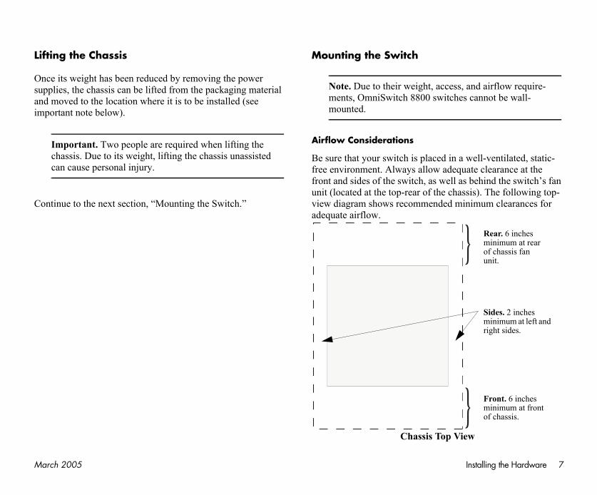
Rear. 6 inches minimum at rear of chassis fan unit.
Front. 6 inches minimum at front of chassis.
Sides. 2 inches minimum at left and right sides.
}
rch 2005
ting the Chassis
ce its weight has been reduced by removing the power pplies, the chassis can be lifted from the packaging material d moved to the location where it is to be installed (see portant note below).
Important. Two people are required when lifting the chassis. Due to its weight, lifting the chassis unassisted can cause personal injury.
ntinue to the next section, “Mounting the Switch.”
Mounting the Switch
Note. Due to their weight, accements, OmniSwitch 8800 switcmounted.
Airflow Considerations
Be sure that your switch is placed infree environment. Always allow adefront and sides of the switch, as welunit (located at the top-rear of the chview diagram shows recommended adequate airflow.
Chassis Top

8 March 2005
Neanve
Mo
If sumoenwhmoremsu
low before installing the
equires three people—two d position it in the rack the chassis to the rack .
k-mount screws. Use the vendor.
ming top heavy, it is ll the switch at the bottom le.
ch in a relay rack, be sure per the rack manufac-
t chassis airflow recom-.
e steps below.
ckets as a template, mark chassis is to be installed.
racket to the front end of ad screws that came with for the positioning and
screws.
Installing the Hardware
ver obstruct the air intake vents located at the bottom-front d bottom-sides of the chassis or the fan unit’s air output nts located at the rear of the chassis.
Note. Clearance is not required at the top and bottom of the chassis.
dule Access Considerations
the switch will be mounted in rack that is immobile, make re that you have adequate clearance to install and remove dules on the front and rear of the chassis. Please allow
ough clearance to install and remove the front fan trays, ich are approximately 15.8 inches long, are the longest dules on the front. And please allow enough clearance to ove the Switch Fabric Modules (SFMs) and power
pplies, which are approximately 6 inches long.
Rack-Mounting
Refer to the important guidelines beOmniSwitch chassis in a rack.
• Rack-mounting the chassis rpeople to hold the chassis anand a third person to secure using the attachment screws
• Alcatel does not provide racscrews supplied by the rack
• To prevent a rack from becorecommended that you instaof the rack whenever possib
• If you are installing the switto install and secure the rackturer’s specifications.
• Refer to page 7 for importanmendations before installing
To rack-mount the switch, follow th
1 Using the rack-mounting brathe holes on the rack where the
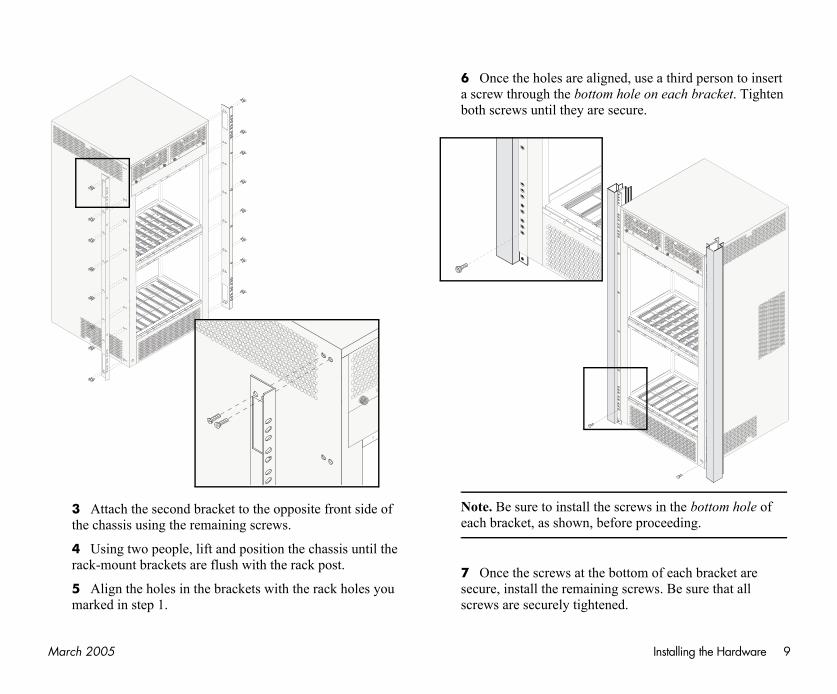
2 Attach one rack-mounting bthe chassis using the Phillips-hethe chassis. See the figure belowplacement of these brackets and
Ma Installing the Hardware 9
use a third person to insert on each bracket. Tighten e.
ws in the bottom hole of proceeding.
m of each bracket are ews. Be sure that all
rch 2005
3 Attach the second bracket to the opposite front side of the chassis using the remaining screws.
4 Using two people, lift and position the chassis until the rack-mount brackets are flush with the rack post.
5 Align the holes in the brackets with the rack holes you marked in step 1.
6 Once the holes are aligned, a screw through the bottom holeboth screws until they are secur
Note. Be sure to install the screeach bracket, as shown, before
7 Once the screws at the bottosecure, install the remaining scrscrews are securely tightened.

10 March 2005
Sta
Thalosusw88
Tobe
hassis power supply bays
ll the power supply upside r supply, note that the on/
et are located at the bottom is located at the top of the
ndle at the front of the hand under the power ght.
he casing into the power supply back until its kplane connector.
OK1OK2
50/60Hz, 8.0 A
230V
CAUTION: THIS UNIT MAY BE EQUIPPED
WITH FOUR POW
ER SUPPLIE CORDS. TO RED
THE RISK OF ELECTRICAL SHOCK, DISCONNE
ALL POWER SUPPLY CORDS BEFORE
SERVICING UNIT.
Installing the Hardware
nd-Alone
e OmniSwitch 8800 can be installed unmounted as a stand-ne unit. Be sure that the installation location is a stable, flat
rface that can accommodate the fully-populated weight of all itches being installed. One fully-populated OmniSwitch 00 weighs approximately 220 lbs (100 Kgs).
Note. OmniSwitch 8800 switches must be installed “right side up.” Never attempt to operate a switch while it is lying on its side.
install the switch as a stand-alone unit, follow the steps low:
1 Use two or more people to move and position the unpopulated chassis upright on the floor or bench where it is to be installed.
2 Be sure that adequate clearance has been provided for chassis airflow and that you have placed the chassis within reach of all required AC outlets. For recommended airflow allowances, refer to page 7. For environmental and electrical requirements, refer to page 3.
Installing Power Supplies
Reinstall the power supplies in the cby following the steps below.
1 Be sure that you do not instadown. When orienting the poweoff switch and power cord sockof the power supply and the fanpower supply.
2 With one hand, grasp the hapower supply. Place your othersupply casing to support its wei
3 Carefully insert the rear of tsupply bay and slide the power connector meets the chassis bac
50/60Hz, 8.0 A
230V
AC OK
DC OK
TEMPFAIL
!
CAUTION: THIS UNIT MAY BE EQUIPPED
WITH FOUR POW
ER SUPPLIE CORDS. TO REDUCE
THE RISK OF ELECTRICAL SHOCK, DISCONNECT
ALL POWER SUPPLY CORDS BEFORE
SERVICING UNIT.
ATTENTION: CET APPAREIL COMPORTE
PLUS D'UN CORDON D'ALIMENTATION. AFIN DE
PREVENIR LES CHOCS ELECTRIQUES, DEBRANCHE
TOUS LES CORDONS D'ALIMENTATION AVANTE DE
FAIRE LA REPARATION.
Ma Installing the Hardware 11
he top of the power cord ewdriver. Do not discard einstall them later.
ord through the top portion
wer cord into the power the power cord is attached
rch 2005
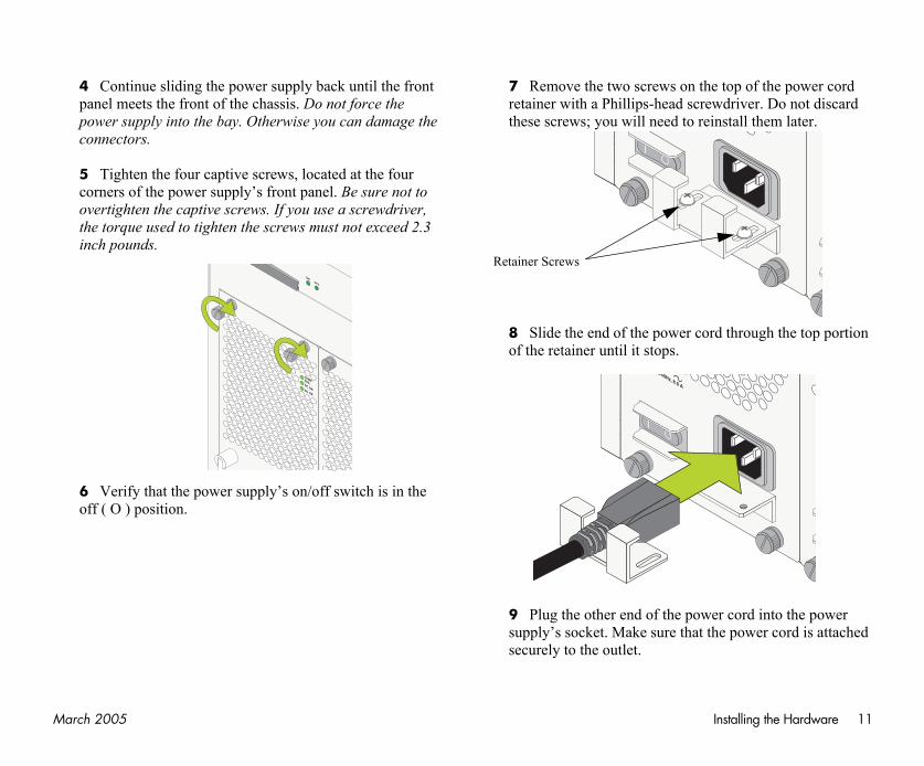
4 Continue sliding the power supply back until the front panel meets the front of the chassis. Do not force the power supply into the bay. Otherwise you can damage the connectors.
5 Tighten the four captive screws, located at the four corners of the power supply’s front panel. Be sure not to overtighten the captive screws. If you use a screwdriver, the torque used to tighten the screws must not exceed 2.3 inch pounds.
6 Verify that the power supply’s on/off switch is in the off ( O ) position.
7 Remove the two screws on tretainer with a Phillips-head scrthese screws; you will need to r
8 Slide the end of the power cof the retainer until it stops.
9 Plug the other end of the posupply’s socket. Make sure thatsecurely to the outlet.
AC OK
DC OK
TEMPFAIL
OK1OK2
Retainer Screws
0/60Hz, 8.0 A

12 March 2005
Strap and Chassis
D) can damage switch terface (NI) and Chassis ound yourself properly installation.
grounding wrist strap and ttom-right of the chassis. the steps below.
ng strap to your wrist.
ctor pin (located at the end ounding lug near the hown.
Installing the Hardware
10 Use a Phillips-head screwdriver to attach the top portion of the retainer with the two Phillips-head screws.
11 Once the power cord is secured in the retainer, plug the power cord into an easily-accessible, properly grounded outlet. Do not use an extension cord.
12 Install all remaining power supplies by repeating steps 1 through 11 for each power supply.
Note. For OmniSwitch 8800 switches using DC power, the power cord connector snaps into the connector socket. A cable retainer is not used.
Important. Do not turn on the power supplies at this time.
Using the Grounding Wrist Grounding Lug
Because electrostatic discharge (EScomponents such as the Network InManagement Modules, you must grbefore continuing with the hardware
For this purpose, Alcatel provides aa grounding lug located near the boTo properly ground yourself, follow
1 Fasten the provided groundi
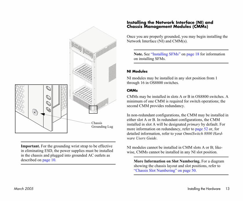
2 Insert the wrist strap’s conneof the strap’s tether) into the grbottom-right of the chassis, as s
Ma Installing the Hardware 13
face (NI) and les (CMMs)
u may begin installing the ).
page 18 for information
slot position from 1
r B in OS8800 switches. A or switch operations; the
e CMM may be installed in figurations, the CMM primary by default. For fer to page 52 or, for mniSwitch 8800 Hard-
MM slots A or B; like-any NI slot position.
mbering. For a diagram slot positions, refer to age 50.
rch 2005
Important. For the grounding wrist strap to be effective in eliminating ESD, the power supplies must be installed in the chassis and plugged into grounded AC outlets as described on page 10.
Installing the Network InterChassis Management Modu
Once you are properly grounded, yoNetwork Interface (NI) and CMM(s
Note. See “Installing SFMs” onon installing SFMs.
NI Modules
NI modules may be installed in anythrough 16 in OS8800 switches.
CMMs
CMMs may be installed in slots A ominimum of one CMM is required fsecond CMM provides redundancy.
In non-redundant configurations, theither slot A or B. In redundant coninstalled in slot A will be designatedmore information on redundancy, redetailed information, refer to your Oware Users Guide.
NI modules cannot be installed in Cwise, CMMs cannot be installed in
More Information on Slot Nushowing the chassis layout and “Chassis Slot Numbering” on p
Chassis Grounding Lug
14 March 2005
BemoCMis Wcomo
ollow the steps below.
hands, carefully slide it component side of the
easily. Do not force the stance is encountered, operly in the card guide. arding chassis card guides
Installing the Hardware
Note. To further reduce exposure to electrostatic discharge (ESD) and physical damage, do not remove more than one module at a time from the factory packaging. Unpack one module, immediately install the module in the chassis, then repeat the sequence for another module.
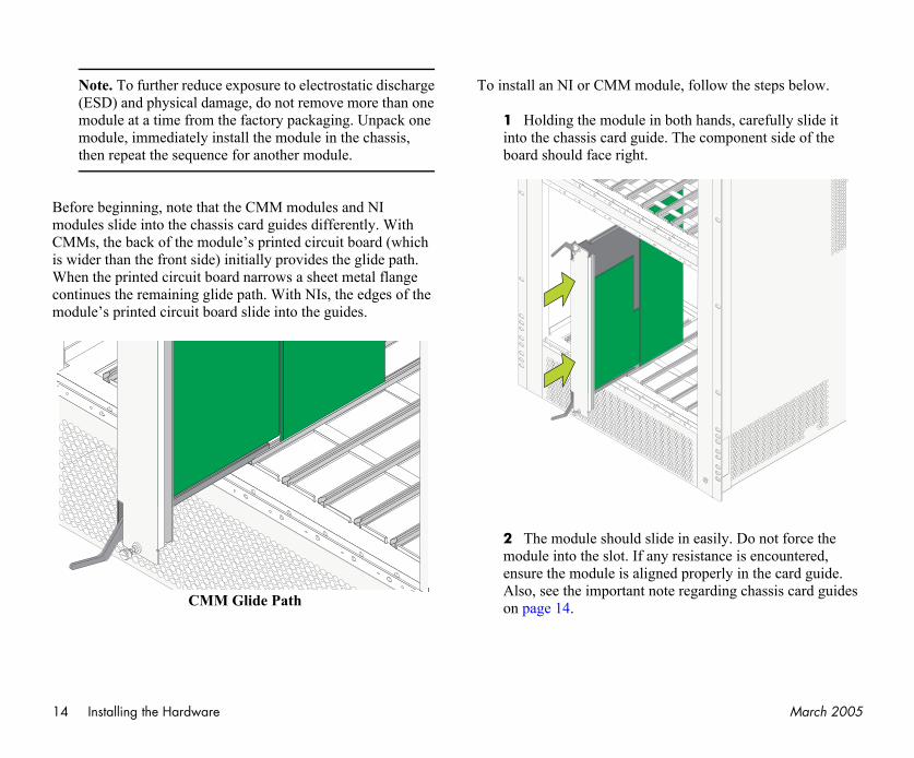
fore beginning, note that the CMM modules and NI dules slide into the chassis card guides differently. With Ms, the back of the module’s printed circuit board (which
wider than the front side) initially provides the glide path. hen the printed circuit board narrows a sheet metal flange ntinues the remaining glide path. With NIs, the edges of the dule’s printed circuit board slide into the guides.
CMM Glide Path
To install an NI or CMM module, f
1 Holding the module in both into the chassis card guide. Theboard should face right.
2 The module should slide in module into the slot. If any resiensure the module is aligned prAlso, see the important note regon page 14.
Ma Installing the Hardware 15
eated, secure the module to o captive screws. Be sure rews. If you use a screw-n the screws must not
s by repeating steps 1
rch 2005
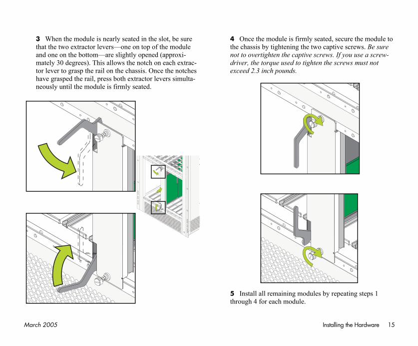
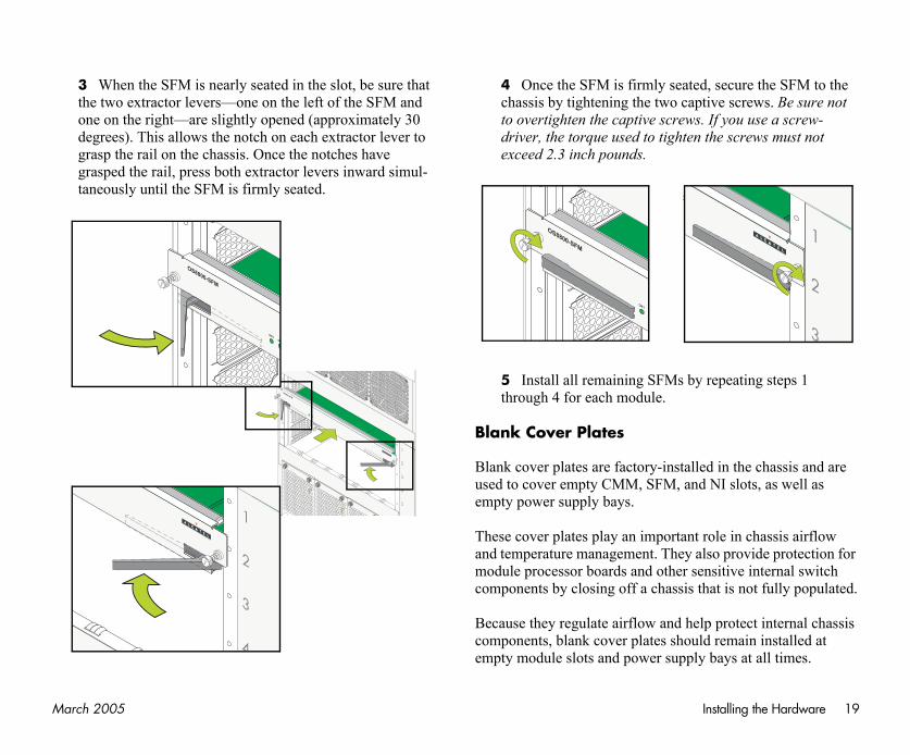
3 When the module is nearly seated in the slot, be sure that the two extractor levers—one on top of the module and one on the bottom—are slightly opened (approxi-mately 30 degrees). This allows the notch on each extrac-tor lever to grasp the rail on the chassis. Once the notches have grasped the rail, press both extractor levers simulta-neously until the module is firmly seated.
4 Once the module is firmly sthe chassis by tightening the twnot to overtighten the captive scdriver, the torque used to tighteexceed 2.3 inch pounds.
5 Install all remaining modulethrough 4 for each module.
16 March 2005
In
If moerssep
To
slot until it clicks into
handle at the front of the ve a MiniGBIC, carefully andle and carefully pull .
d slide in easily. Do not tance is encountered, properly. Forcing the age the unit, as well as le.
LIN
KT
Installing the Hardware
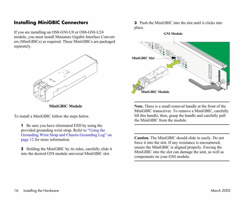
stalling MiniGBIC Connectors
you are installing an OS8-GNI-U8 or OS8-GNI-U24 dule, you must install Miniature Gigabit Interface Convert- (MiniGBICs) as required. These MiniGBICs are packaged arately.
install a MiniGBIC follow the steps below.
1 Be sure you have eliminated ESD by using the provided grounding wrist strap. Refer to “Using the Grounding Wrist Strap and Chassis Grounding Lug” on page 12 for more information.
2 Holding the MiniGBIC by its sides, carefully slide it into the desired GNI module universal MiniGBIC slot.
3 Push the MiniGBIC into theplace.
Note. There is a small removal MiniGBIC transceiver. To remolift this handle; then, grasp the hthe MiniGBIC from the module
Caution. The MiniGBIC shoulforce it into the slot. If any resisensure the MiniGBIC is alignedMiniGBIC into the slot can damcomponents on your GNI modu
TX
RX
MiniGBIC Module
LIN
K
AC T
LIN
K
AC T
LIN
K
AC T
AC
8
7
6
MiniGBIC Module
MiniGBIC Slot
GNI Module
Ma Installing the Hardware 17
In
If XeXe
To
PAK module with the R1’s circuit board as
ides, carefully slide it into
ide in easily. Do not force is encountered, ensure the cing the Xenpak into the
ll as components on your
e
rch 2005
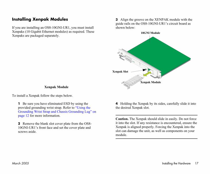
stalling Xenpak Modules
you are installing an OS8-10GNI-UR1, you must install npaks (10 Gigabit Ethernet modules) as required. These npaks are packaged separately.
install a Xenpak follow the steps below.
1 Be sure you have eliminated ESD by using the provided grounding wrist strap. Refer to “Using the Grounding Wrist Strap and Chassis Grounding Lug” on page 12 for more information.
2 Remove the blank slot cover plate from the OS8-10GNI-UR1’s front face and set the cover plate and screws aside.
3 Align the groove on the XENguide rails on the OS8-10GNI-Ushown below:
4 Holding the Xenpak by its sthe desired Xenpak slot.
Caution. The Xenpak should slit into the slot. If any resistanceXenpak is aligned properly. Forslot can damage the unit, as wemodule.
Xenpak Module RX
TX
OK
1
OK
2
Tx
Rx
Lin
k
Tx
2
1
Po
rtR
ed
un
da
nc
y
Rx
Lin
k
RX
TX
Xenpak Modul
Xenpak Slot
10GNI Module
18 March 2005
In
OnSwsiscoalwmo
SFof SFdayo
here.
re to electrostatic discharge not remove more than one packaging. Unpack one FM in the chassis, then SFM.
nds, carefully slide it into ponent side of the board
ily. Do not force the SFM encountered, ensure the card guide.
1
5
4
3
2
Installing the Hardware
stalling SFMs
ce you are properly grounded, you may begin installing the itch Fabric Modules (SFMs) on the back side of the chas-. Because electrostatic discharge (ESD) can damage switch mponents such as the Switch Fabric Modules, you must
ays ground yourself properly before removing or adding a dule. Refer to page 12 for more information.
Note. See “Installing the Network Interface (NI) and Chassis Management Modules (CMMs)” on page 13 for information on installing CMMs and NIs.
Ms may be installed in SFM slots 1 through 5. A minimum four (4) SFMs are required for switch operations; the fifth M provides redundancy. For more information on redun-ncy, refer to page 52 or, for detailed information, refer to ur OmniSwitch 8800 Hardware Users Guide.
More Information on Slot Numbering. For a diagram showing the chassis layout and slot positions, refer to page 51.
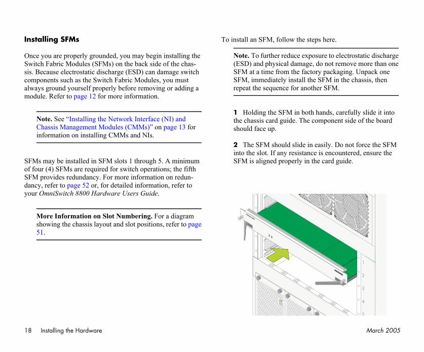
To install an SFM, follow the steps
Note. To further reduce exposu(ESD) and physical damage, doSFM at a time from the factorySFM, immediately install the Srepeat the sequence for another
1 Holding the SFM in both hathe chassis card guide. The comshould face up.
2 The SFM should slide in easinto the slot. If any resistance isSFM is aligned properly in the
AC OK
DC OK
TEMPFAIL
OK1OK2
OS8800-SFM
Ma Installing the Hardware 19
ed, secure the SFM to the ptive screws. Be sure not s. If you use a screw-n the screws must not
y repeating steps 1
lled in the chassis and are nd NI slots, as well as
t role in chassis airflow also provide protection for sensitive internal switch that is not fully populated.
elp protect internal chassis uld remain installed at ly bays at all times.
1
3
2
rch 2005
3 When the SFM is nearly seated in the slot, be sure that the two extractor levers—one on the left of the SFM and one on the right—are slightly opened (approximately 30 degrees). This allows the notch on each extractor lever to grasp the rail on the chassis. Once the notches have grasped the rail, press both extractor levers inward simul-taneously until the SFM is firmly seated.
4 Once the SFM is firmly seatchassis by tightening the two cato overtighten the captive screwdriver, the torque used to tighteexceed 2.3 inch pounds.
5 Install all remaining SFMs bthrough 4 for each module.
Blank Cover Plates
Blank cover plates are factory-instaused to cover empty CMM, SFM, aempty power supply bays.
These cover plates play an importanand temperature management. Theymodule processor boards and other components by closing off a chassis
Because they regulate airflow and hcomponents, blank cover plates shoempty module slots and power supp
1
5
4
3
2
OK1OK2
OS8800-SFM
AC OK
DC OK
TEMPFAIL
AC OK
DC OK
TEMPFAIL
1
4
3
2
OK1OK
OS8800-SFM
OK1
OS8800-SFM
20 March 2005
Onneap
Se
Thserintcochto
s
erial connection are as
settings, refer to ettings” on page 29.
C
9600
none
8
1
Connections and Cabling
ce your switch is properly installed, you should connect all twork and management cables required for your network plications. Connections may include:
• Serial cable to the console port
• Ethernet cable to the Ethernet Management Port (EMP) on the CMM
• Fiber cables to all required MiniGBICs and Xenpaks
• Ethernet cables to all required RJ-45 ports on copper ENI and GNI modules.
rial Connection to the Console/Modem Port
e console port, located on the CMM module, provides a ial connection to the switch and is required when logging o the switch for the first time. By default, this female DB-9 nnector provides a DCE console connection. However, by anging the onboard jumper setting, the port can be changed a DTE modem connection.
Modem Connections. If you require a modem connec-tion to the switch, you must convert the console port to support modem connections by installing a hardware jumper on the CMM. Refer to your OmniSwitch 8800 Hardware Users Guide for details.
Serial Connection Default Setting
The factory default settings for the sfollows:
For information on modifying these“Modifying the Serial Connection S
onnections and Cabling
baud rate
parity
data bits (word size)
stop bits
Ma Connections and Cabling 21
EM
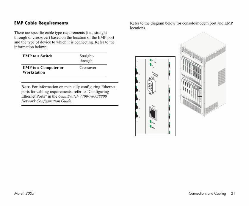
Ththraninf
ole/modem port and EMP
OS
-GN
I-C8
ACT
LINK
ACT
LINK
ACT
LINK
ACT
LINK
ACT
LINK
ACT
LINK
ACT
LINK
ACT
LINK
OK1
OK2
1
2
3
4
5
6
7
8
OS
8800-C
MM
OK1
OK2
PRI
SEC
TEMP
FAN
STATUS
CONSOLE/ MODEM
1
2
3
ACT
LINK
ENET
OS
-GN
I-U8
LINK
ACT
LINK
ACT
LINK
ACT
LINK
ACT
LINK
ACT
LINK
ACT
LINK
ACT
LINK
ACT 8
7
6
5
4
3
2
1
OK1
OK2
OS
-GN
I-U8
LINK
ACT
LINK
ACT
LINK
ACT
LINK
ACT
LINK
ACT
LINK
ACT
LINK
ACT
LINK
ACT 8
7
6
5
4
3
2
1
OK1
OK2
OS
-GN
I-U8
LINK
ACT
LINK
ACT
LINK
ACT
LINK
ACT
LINK
ACT
LINK
ACT
LINK
ACT
LINK
ACT 8
7
6
5
4
3
2
1
OK1
OK2
OS
-GN
I-U8
LINK
ACT
LINK
ACT
LINK
ACT
LINK
ACT
LINK
ACT
LINK
ACT
LINK
ACT
LINK
ACT 8
7
6
5
4
3
2
1
OK1
OK2
OS
-EN
I-C24
1
2
12
14
3
5
7
9
11
13
15
17
19
21
23
OK1
OK2
24
OS
8800-C
MM
OK1
OK2
PRI
SEC
TEMP
FAN
STATUS
CONSOLE/ MODEM
1
2
3
ACT
LINK
ENET
OS
-EN
I-C24
1
2
12
14
3
5
7
9
11
13
15
17
19
21
23
OK1
OK2
24
OS
-EN
I-C24
1
2
12
14
3
5
7
9
11
13
15
17
19
21
23
OK1
OK2
24
OS
-EN
I-C24
1
2
12
14
3
5
7
9
11
13
15
17
19
21
23
OK1
OK2
24
OS
-EN
I-C24
1
2
12
14
3
5
7
9
11
13
15
17
19
21
23
OK1
OK2
24
rch 2005
P Cable Requirements
ere are specific cable type requirements (i.e., straight-ough or crossover) based on the location of the EMP port d the type of device to which it is connecting. Refer to the ormation below:
Note. For information on manually configuring Ethernet ports for cabling requirements, refer to “Configuring Ethernet Ports” in the OmniSwitch 7700/7800/8800 Network Configuration Guide.
Refer to the diagram below for conslocations.
EMP to a Switch Straight-through
EMP to a Computer or Workstation
CrossoverO
S-G
NI-C
8
ACT
LINK
ACT
LINK
ACT
LINK
ACT
LINK
ACT
LINK
ACT
LINK
ACT
LINK
ACT
LINK
OK1
OK2
1
2
3
4
5
6
7
8
OS
-GN
I-C8
ACT
LINK
ACT
LINK
ACT
LINK
ACT
LINK
ACT
LINK
ACT
LINK
ACT
LINK
ACT
LINK
OK1
OK2
1
2
3
4
5
6
7
8
OS
-GN
I-C8
ACT
LINK
ACT
LINK
ACT
LINK
ACT
LINK
ACT
LINK
ACT
LINK
ACT
LINK
ACT
LINK
OK1
OK2
1
2
3
4
5
6
7
8
OS
-EN
I-C24
1
2
12
14
3
5
7
9
11
13
15
17
19
21
23
OK1
OK2
24
OS
-EN
I-C24
1
2
12
14
3
5
7
9
11
13
15
17
19
21
23
OK1
OK2
24
OS
-EN
I-C24
1
2
12
14
3
5
7
9
11
13
15
17
19
21
23
OK1
OK2
24
13
15
17
19
21
23
FAN
CONSOLE/ MODEM
2
3
ACT
LINK
ENET

22 March 2005
Nocothesu
Co
Ththimabo
Fone
ted, make sure the boot ot process takes several o not display as indicated , contact Alcatel Customer
d NI LED states, see pages ower supply LED states, are Users Guide.
ted and you have accessed software via the console witch’s Command Line information. Continue to 23.
B
Solid Green
Solid Green
Solid Green
Blinking Green
Solid Green
Blinking Green
Off
Solid Green
Solid Green
Booting the Switch
w that you have installed the switch components and nnected all required cables, you can boot the switch. To boot switch, simply turn the on/off switch for all installed power
pplies to the on ( | ) position.
Note. If you have more than one power supply installed, be sure to turn on each power supply in rapid succession, (i.e., within a few seconds of each other). This ensures that there will be adequate power for all NI modules when they boot.
mponent LEDs
e boot process takes a few moments to complete. During s process, the LEDs on the CMM, SFM, and NI modules y flash and change color, indicating different stages of the ot.
llowing a successful boot, the LEDs on all switch compo-nts, including power supplies, should display as follows:
If the LEDs do not display as indicaprocess is completed. Again, the bomoments to complete. If the LEDs dfollowing a complete boot sequenceSupport.
For descriptions of CMM, SFM, an53 through 63. For information on prefer to the OmniSwitch 8800 Hardw
Once the switch has completely booyour computer’s terminal emulationport, you are ready to log in to the sInterface (CLI) and configure basic“Your First Login Session” on page
ooting the Switch
CMM OK1 Solid Green
CMM OK2 Blinking Green
CMM TEMP Solid Green
CMM FAN 1 Solid Green
CMM FAN 2
CMM FAN 3
SFM OK1
SFM OK2
NI OK1
NI OK2
Power Supply TEMP Fail
Power Supply DC OK
Power Supply AC OK
Ma Your First Login Session 23
In shses
itch
you will be prompted for a . During this first login
and one password option is
min
at the login prompt:
ord, switch, at the pass-
includes information such system date, displays— pt:
witch 8000
13, 2004.
tel Internetworking, Inc.
k of Alcatel Internetwork-United States Patent and
Y
rch 2005
order to complete the setup process for the switch, you ould complete the following steps during your first login sion:
• Log in to the switch
• Set IP address information for the Ethernet Management Port (EMP)
• Unlock session types
• Change the login password
• Set the date and time
• Set optional system information
• Save your changes
Important. You must be connected to the switch via the console port before initiating your first login session.
Logging In to the Sw
When you first log in to the switch, login (i.e., user) name and passwordsession, only one user name option available:
• Login (i.e., user name)—ad
• Password—switch
To log in to the switch, enter admin
login: admin
Next, enter the factory default passwword prompt:
password: switch
The default welcome banner, whichas the current software version and followed by the CLI command prom
Welcome to the Alcatel OmniS
Software Version 5.1.5, June
Copyright(c), 1994-2004 AlcaAll Rights reserved.
OmniSwitch(TM) is a trademaring, Inc. registered in the Trademark Office.
our First Login Session
24 March 2005
SethThmo(Nthr
In tioad
Tofol
ers at the CLI prompt. The
ot empipaddr, followed r the EMP. For example:
168.22.2.120
ayipaddr, followed by the r the EMP. For example:
ipaddr 168.22.2.254
by entering show at the
: 168.22.2.120 : 168.22.2.254
shown)
et mask is Class C ange this default value, mand at the boot prompt.
Your First Login Session
More Information On User Accounts. A user account includes a login name, password, and user privileges. Privileges determine whether the user has read or write access to the switch and which commands the user is authorized to execute.
For detailed information on setting up and modifying user accounts and user privileges, refer to the “Managing Switch User Accounts” chapter of your OmniSwitch 7700/7800/8800 Switch Management Guide.
tting IP Address Information for e EMPe Ethernet Management Port (EMP) is located on the CMM dule. The EMP allows you to bypass the Network Interface I) modules and manage the switch over the network directly ough the CMM.
order to ping the switch through the EMP Ethernet connec-n, you must change the port’s default IP and gateway dresses.
change the default IP and gateway addresses, refer to the lowing steps.
Note. You must be connected to the switch via the console port before attempting to change IP address information. Otherwise, an error message will display.
1 Enter modify boot parametboot prompt displays:
Boot >
2 At the boot prompt, enter boby the new default IP address fo
Boot > boot empipaddr
3 Next, enter boot empgatewnew default gateway address fo
Boot > boot empgateway
4 Verify your current changesboot prompt:
Boot > showEdit buffer contents:EMP IP Address EMP Gateway IP Address
(additional table output not
Subnet Mask. The default subn(255.255.255.0). If you must chuse the boot empnetmask com
Ma Your First Login Session 25
pes
itch 8800 switches. As a or the first time, you must . All other session types .) are “locked out” until ser.
ession types is
types, you are granting ons (e.g., Telnet). As a ect user login and pass- the switch. For more
refer to the “Managing r OmniSwitch 7700/7800/e.
e following command
default local
es
n a one-by-one basis. For only, enter the following
telnet local
rch 2005
Access to the EMP. By default, only devices in the same subnet as the EMP will be able to manage the switch through that port. For information on allowing devices in other subnets to manage the switch via the EMP, refer to the OmniSwitch 8800 Hardware Users Guide.
5 Save these changes to the switch’s running memory by entering commit system at the boot prompt:
Boot > commit system
This will immediately enable your changes and allow users to ping the EMP. Note, however, that these changes have not yet been saved to the switch’s boot.params file and will be lost if the switch is rebooted.
6 To permanently save these changes to the boot.params file, enter commit file at the boot prompt:
Boot > commit file
Changes will be preserved following a switch reboot.
7 Return to the CLI prompt by entering exit at the boot prompt.
Important. Although you have configured the EMP with valid IP address information, you will not be able to access the switch through this port for Telnet, FTP, WebView, or SNMP sessions until you have unlocked these remote session types. See “Unlocking Session Types” for more information.
Unlocking Session Ty
Security is a key feature on OmniSwresult, when you access the switch fuse a direct console port connection(Telnet, FTP, WebView, SNMP, etcthey are manually unlocked by the u
The CLI command used to unlock saaa authentication.
Note. When you unlock sessionswitch access to non-local sessiresult, users who know the corrword will have remote access toinformation on switch security,Switch Security” chapter of you8800 Switch Management Guid
Unlocking All Session Types
To unlock all session types, enter thsyntax at the CLI prompt:
-> aaa authentication
Unlocking Specified Session Typ
You can also unlock session types oexample, to unlock Telnet sessions command:
-> aaa authentication
26 March 2005
Toing
Yocotypsio
Ho
Onof
assword
in user sessions by follow-
d into the switch as user the Switch” on page 23).
d and press <Enter>.
p to 47 characters long) at low).
hould be a string of non-ses the first occurrence of identify the password. For r is the same as engr. A 735.
enter the password. Enter
ecurely record all new ed passwords on estricted.
Your First Login Session
unlock WebView (HTTP) sessions only, enter the follow- command:
-> aaa authentication http local
u cannot specify more than one session type in a single mmand line. However, you can still unlock multiple session es by using the aaa authentication command in succes-n. For example:
-> aaa authentication http local-> aaa authentication telnet local-> aaa authentication ftp local
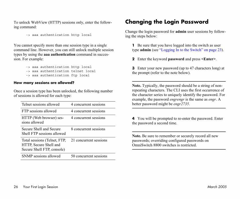
w many sessions are allowed?
ce a session type has been unlocked, the following number sessions is allowed for each type:
Changing the Login P
Change the login password for adming the steps below:
1 Be sure that you have loggetype admin (see “Logging In to
2 Enter the keyword passwor
3 Enter your new password (uthe prompt (refer to the note be
Note. Typically, the password srepeating characters. The CLI uthe character series to uniquelyexample, the password engrengbetter password might be engr2
4 You will be prompted to re-the password a second time.
Note. Be sure to remember or spasswords; overriding configurOmniSwitch 8800 switches is r
Telnet sessions allowed 4 concurrent sessions
FTP sessions allowed 4 concurrent sessions
HTTP (Web browser) ses-sions allowed
4 concurrent sessions
Secure Shell and Secure Shell FTP sessions allowed
8 concurrent sessions
Total sessions (Telnet, FTP, HTTP, Secure Shell and Secure Shell FTP, console)
21 concurrent sessions
SNMP sessions allowed 50 concurrent sessions
Ma Your First Login Session 27
Netheadtiofol
Alcothe
Se
ThGr
If yoswzopleen
ter the following
ings time enable
supported. For detailed one for the switch, refer to witch Management Guide.
Time
y entering system time, m:ss. For example:
0
e time value shown in the o 6:35 PM.
h, enter system date, dd/yyyy. For example:
002
rch 2005
w password settings are automatically saved in real time to local user database; the user is not required to enter an
ditional command in order to save the password informa-n. Also note that new password information is retained lowing a reboot.
l subsequent login sessions—including those through the nsole port—will require the new password in order to access switch.
User Accounts. The switch allows a maximum of 50 user accounts in the local user database. For information on creating additional user types and assigning individual passwords, refer to the “Managing Switch User Accounts” chapter of your Switch Management Guide.
tting the System Time Zone
e switch’s default time zone is UTC (also referred to as eenwich Mean Time).
you require a time zone that is specific to your region—or if u need to enable Daylight Savings Time (DST) on the itch—you can configure these settings via the system time-ne and system daylight savings time commands. For exam-, to set the system clock to run on Pacific standard time,
ter the following command.
-> system timezone pst
To enable Daylight Savings time, encommand.
-> system daylight sav
Many other time zone variables are information on configuring a time zyour OmniSwitch 7700/7800/8800 S
Setting the Date and
Set the current time for the switch bfollowed by the current time in hh:m
-> system time 18:35:0
The switch uses a 24-hour clock; thabove example would set the time t
To set the current date for the switcfollowed by the current date in mm/
-> system date 12/27/2
28 March 2005
SeInThsy
Sp
Anchfintio
Tofolincen
Fo
efined text description for
tem name, followed by a ters. If you include spaces sure to enclose the string
ng Switch 3"
tion
ysical labeling system for (es). Examples include nique identifier (e.g., the chassis.
been implemented or if cation from a remote site, ry useful.
system location, followed aracters. If you include ing, be sure to enclose the
ab--NE Corner Rack"
Your First Login Session
tting Optional System formationis section provides information on configuring optional stem parameters, including:
• the switch’s administrative contact
• a system name
• the switch’s physical location
ecifying an Administrative Contact
administrative contact is the person or department in arge of the switch. If a contact is specified, users can easily d the appropriate network administrator if they have ques-ns or comments about the switch.
specify an administrative contact, enter system contact, lowed by a text string of up to 254 characters. If you lude spaces between words in the text string, be sure to
close the string in quotes (" ").
r example:
-> system contact "JSmith X477 [email protected]"
Specifying a System Name
The system name is a simple, user-dthe switch.
To specify a system name, enter systext description of up to 254 characbetween words in the text string, bein quotes (" ").
For example:
-> system name "Engineeri
Specifying the Switch’s Loca
It is recommended that you use a phlocating and identifying your switchplacing a sticker or placard with a uswitch’s default IP address) on each
However, if no labeling system has you need to determine a switch’s loentering a system location can be ve
To specify a system location, enter by a text description of up to 254 chspaces between words in the text strstring in quotes (" ").
For example:
-> system location "NMS L
Ma Your First Login Session 29
V
Topro
Sa
Onyopro
Wauantio
Connection
ults are listed on page 20. rial connection settings stop bits), refer to the
the switch via the console e serial connection ssage will display.
ers at the CLI prompt. The
er boot serialbaudrate, te value. Options include t), 19200, 38400, 57600, le:
rate 19200
o speeds above 9600 baud em uploads.
enter boot serialparity, alue. Options include none ample:
rch 2005
iewing Your Changes
view your current changes, enter show system at the CLI mpt.
ving Your Changes
ce you have configured this basic switch information, save ur changes by entering write memory at the CLI command mpt.
hen the write memory command is entered, changes are tomatically saved to the main configuration file (boot.cfg) d placed in the /flash/working directory. For more informa-n on the boot.cfg file, refer to page 38.
Note. If the switch reboots following a write memory command entry, the switch will run from the /flash/certified directory. As a result, subsequent configu-ration changes cannot be saved using the write memory command until the switch is once again running from the /flash/working directory. See page 40 for important infor-mation on these directories.
Modifying the Serial SettingsThe switch’s serial connection defaIf you wish to modify the default se(i.e., baud rate, parity, data bits, andfollowing steps.
Note. You must be connected toport before attempting to changsettings. Otherwise, an error me
1 Enter modify boot parametboot prompt displays:
Boot >
2 To change the baud rate, entfollowed by the desired baud ra1200, 2400, 4800, 9600 (defaul76800, and 115200. For examp
Boot > boot serialbaud
Note. Setting the console port tcan cause problems with Zmod
3 To change the parity value, followed by the desired parity v(default), even, and odd. For ex

30 March 2005
ges in real time to the tering commit system at
nt things to consider when and to save serial connec-
ecome illegible due to on settings between the lation software.
m command only, changes ch’s boot.params file and ebooted. To save changes r to step 7.
entering exit at the boot
ess. Your Alcatel dy for additional configu- to the following sections switch, as well as addi-
Your First Login Session
Boot > boot serialparity even
4 To change the data bits (i.e., word size) value, enter boot serialwordsize, followed by the number of data bits. Options include 7 and 8 (default). For example:
Boot > boot serialwordsize 7
5 To change the stop bits value, enter boot serialstop-bits, followed by the number of stop bits. Options include 1 (default) and 2. For example:
Boot > boot serialstopbits 2
6 Verify your current changes by entering show at the boot prompt:
Boot > showEdit buffer contents:Serial (console) baud : 19200Serial (console) parity : evenSerial (console) stopbits : 2Serial (console) wordsize : 7
(additional table output not shown)
7 You can save your changes to the boot.params file by entering commit file at the boot prompt:
Boot > commit file
When the commit file command is used, changes will not be enabled until after the next switch reboot.
8 You can also save your chanswitch’s running memory by enthe boot prompt:
Boot > commit system
Caution. There are two importausing the commit system commtion changes:
• Output to the terminal may bincompatible serial connectiswitch and the terminal emu
• If you use the commit systewill not be saved to the switwill be lost if the switch is rto the boot.params file, refe
9 Return to the CLI prompt byprompt.
This completes the initial setup procOmniSwitch 8800 switch is now rearation and network operation. Referfor more information on using yourtional built-in features.
Ma CLI Basics 31
ThanTh
ThassincmeCLSw
C
Thing
00 terminal emulation; limited if your terminal tting other than vt100.
g command syntax, the rrect the error. Whenever a ators are displayed:
g the type of error.ing where the error
rt mac status
rt mac status
"port"
the command, the error and the carat indicates r this example, the valid
c status
C
rch 2005
e Command Line Interface (CLI) allows you to configure d monitor your switch by entering single-line commands. e CLI can be accessed through terminal or Telnet sessions.
Note. Configuring the switch using the CLI is also referred to as “online configuration.”
e following section provides basic information on CLI istance features. For detailed information on the CLI, luding syntax conventions, usage rules, command docu-ntation, and a quick reference card, refer to the OmniSwitch I Reference Guide and the OmniSwitch 7700/7800/8800 itch Management Guide.
LI Assistance Features
e CLI provides built-in features that assist you while enter- commands. These features include:• Syntax checking• Command line help• Partial keyword completion• Deleting and inserting characters• Previous command recall• Prefix recognition• Prefix prompt• Command history
Note. The software supports vt1CLI assistance features may beemulation software is using a se
Syntax Checking
If you make a mistake while enterinCLI provides clues about how to cocommand error is entered, two indic
• An Error message describin• A carat (^) character indicat
occurred.
For example, the syntax-> show vlan router po
results in the following error:
-> show vlan router po ^ERROR: Invalid entry:
Because port is not valid syntax formessage shows it as an invalid entrywhere the problem has occurred. Focommand syntax is
-> show vlan router ma
LI Basics
32 March 2005
Co
Thmaheen
at cainc
Ththetheco
Soinf<hco
n
gnition feature. Instead of ype only the minimum uely identify the keyword, ll complete the keyword e command line.
rs to uniquely identify the have no effect.
elong to an applicable remove the characters and position.
cters by using the Back-ackspace key deletes each rom right to left.
Delete key, use the Left e left of the character to be emove characters to the
CLI Basics
mmand Line (?) Help
e CLI provides additional help in the form of the question rk (?) character. The ? character provides information that
lps you build your command syntax. For example, if you ter
-> show vlan router
the command line and are unsure of the next keyword, you n enter the ? character for additional options (be sure to lude a space between the last keyword and the ? character):
-> show vlan router ? ^
MAC IP (Vlan Manager Command Set)
e carat character (^) indicates the point where you invoked command line help. Possible keyword options, along with corresponding command set, are displayed. Here, you can
ntinue building the command by entering either mac or ip.
me command completion options may indicate user-defined ormation. For example: <string>, <slot/port>, h:mm:ss>, etc. The option <cr> indicates that the mmand can be completed by pressing <Enter>.
Note. The ? character can be entered at any time. In addi-tion, you can type the ? character alone at the CLI prompt to display root keywords for all command sets.
Partial Keyword Completio
The CLI has a partial keyword recotyping an entire keyword, you can tnumber of characters needed to uniqthen press the Tab key. The CLI wiand place the cursor at the end of th
If you do not enter enough charactekeyword, pressing the Tab key will
If you enter characters that do not bkeyword, pressing the Tab key willplace the cursor back to its previous
Deleting Characters
You can delete CLI command charaspace key or the Delete key. The Bcharacter in the line, one at a time, f
To change incorrect syntax with theArrow key to move the cursor to thdeleted, then use the Delete key to rright of the cursor.

Ma CLI Basics 33
In
Touspocofola c
Tolinusanex
Pr
ToUpdisbyins
hat reduces redundant monly-used prefix infor-LI assumes this stored
mmand is entered. For
tore the vlan 32 prefix
pport prefix recognition:
rch 2005
serting Characters
insert a character between characters that are already typed, e the Left and Right Arrow keys to place the cursor into sition, then type the new character. Once the syntax is rrect, execute the command by pressing <Enter>. In the lowing example, the user enters the wrong syntax to execute ommand. The result is an error message.
-> show micrcode ^ERROR: Invalid entry: "micrcode"
correct the syntax without retyping the entire command e, use the !! command to recall the previous syntax. Then, e the Left Arrow key to position the cursor between the “r” d the “c” characters. To insert the missing character for this ample, type “o” as shown:
-> !!-> show microcode
evious Command Recall
recall the last command executed by the switch, press the Arrow key at the prompt and the previous command will play on your screen. You can execute the command again pressing <Enter> or you can edit it first by deleting or erting characters.
Prefix Recognition
Prefix recognition is a CLI feature tcommand line entry by storing commation for certain commands. The Cprefix information when the next coexample, if you enter
-> vlan 32
at the command line, the CLI will sinformation.
The following command families su
• AAA
• Interface
• Link Aggregation
• Quality of Service (QoS)
• Spanning Tree
• VLAN Management

34 March 2005
Pr
Yothe
Afincspwh
Tofol
Co
Yoco
ers
s are displayed lower in the y command will always be
history list by entering an :
from the history list (in CLI prompt.
d in the history list by ). For example:
s displayed in the history mand. For example:
ngs, use the show history e:
ters
CLI Basics
efix Prompt
u can set the CLI to display the current command prefix as command prompt by entering the following command:
-> prompt prefix
ter entering this command, your command prompt will lude current stored prefix information until a new prompt is
ecified. For example, the following is a prompt for a user o has begun configuring VLAN 32:
-> vlan 32
set the prompt back to the default arrow ( -> ), enter the lowing syntax, exactly as shown, at the prefix prompt:
prompt string ->
mmand History
u can view a list of up to 30 of the most recently executed mmands via the show history command. For example:
-> show history1 aaa authentication default local2 password3 system timezone pst4 system daylight savings time enable5 system time 14:58:006 system date 11/06/20027 system contact "JSmith [email protected]"8 system name EngSwitch39 system location "NMS Lab--NE Rack"10 show system
11 modify boot paramet12 show history
Note that the most recent commandlist. For this reason, the show historlisted last.
You can recall commands from the exclamation point ( ! ). For example
-> !4-> show temperature
The CLI prints the fourth commandthis case, show temperature) at the
You can also recall the last commanentering two exclamation points ( !!
-> !!-> show history
To specify the number of commandlist (1 - 30), use the history size com
-> history size 10
To view the current history list settiparameters command. For exampl
-> show history parameHistory size: 30CurrentSize: 10Index Range: 1-10
Ma CLI Basics 35
Co
Omfeacotiocoas a s
ReingrelOm
En
Bylog
via the command-log nd.log is automatically ry. Once enabled, configu-mand line will be
logging is disabled.
byte capacity. This capac-ent commands to be logging information is ommand history informa-.
nnot be deleted while the bled. Before attempting to le command logging.
nd logging, refer to the Management Guide.
rch 2005
mmand Logging
niSwitch 8800 switches provide command logging. This ture allows users to record up to 100 of the most recent
mmands entered via Telnet and console sessions. In addi-n to a list of commands entered, the results of each mmand entry are recorded. Results include information such whether a command was executed successfully, or whether yntax or configuration error occurred.
Note. The command history feature differs from the command logging feature in that command history buff-ers up to 30 of the most recent commands. The command information is not written to a separate log file. Also, the command history feature includes only general keyword syntax (i.e., it does not record full syntax, date and time, session IP address, and entry results). For more informa-tion on command history, refer to page 34.
fer to the sections below for more information on configur- and using CLI command logging. For detailed information ated to command logging commands, refer to the niSwitch CLI Reference Guide.
abling Command Logging
default, command logging is disabled. To enable command ging on the switch, enter the following command:
-> command-log enable
When command logging is enabledenable syntax, a file called commacreated in the switch’s /flash directoration commands entered on the comrecorded to this file until command
The command.log file has a 66402ity allows up to 100 of the most recrecorded. Because all CLI commandarchived to the command.log file, ction will be lost if the file is deleted
Note. The command.log file cacommand logging feature is enaremove the file, be sure to disab
For detailed information on commaOmniSwitch 7700/7800/8800 Switch
36 March 2005
C
ThhecotheGu
wr
sh
vlash
ip
sh
sh
sh
basic hardware and status ion for CMM modules in is. the status and configura-witch Fabric Modules
basic information about h. the version of software installed on the switch. current Telnet or console
the amount of time before d console sessions will
.
CLI Basics
ommon CLI Commands
e following table lists some basic CLI commands that will lp you get acquainted with the CLI interface. Enter each mmand exactly as shown. For complete descriptions of se commands, refer to your OmniSwitch CLI Reference ide.
ite memory Saves current configuration changes to the /flash/working directory’s boot.cfg file. For more information, refer to page 38.
ow running-directory Displays the current running direc-tory. For more information, refer to page 40.
n Creates a new VLAN.ow vlan Displays a list of VLANs config-
ured on the switch.interface Configures an IP interface to
enable IP routing on a VLAN.ow chassis Displays basic configuration and
status information for the switch chassis.
ow module Displays basic information for all modules installed in the chassis. Modules include primary and sec-ondary CMMs and Network Inter-face (NI) modules.
ow ni Displays basic hardware and status information for NI modules installed in the switch.
show cmm Displaysinformatthe chass
show fabric Displaystion of S(SFMs).
show system Displaysthe switc
show microcode Displayscurrently
exit Ends thesession.
session timeout ModifiesTelnet antime out
Ma CLI Basics 37
O
YoASingintfile
Ananswedloa
BetioMmaan
Sy
Offuncofil
File to be Applied
mediately, or you can t a specific date and time s passed. Timer sessions sks such as synchronized
ts of the n
witch’s current configura-ptured configuration d offline at any time. Trou- aggregate network infor-
uration files for a single s allows easy cloning of requiring multiple, simi-lace the snapshot file in the es) you want to configure
configuring and the e “Working with Configu-itch 7700/7800/8800
rch 2005
ffline Configuring
u can configure OmniSwitch 8800 switches using an CII-based text file. This is referred to as offline configur-. With offline configuring, CLI commands may be typed o a text document (referred to as a text-based configuration ) and then uploaded and applied to the switch.
ASCII-based configuration file can be viewed or edited at y time using a standard text editor (e.g., WordPad). The itch also offers its own text editing buffer, so a file can be ited in the flash file directory without having to be down-ded to a workstation.
cause they are portable, stand-alone documents, configura-n files allow users to easily clone switch configurations. oreover, the ability to store a broad range of network infor-tion in a single text file facilitates troubleshooting, testing,
d overall network readability.
ntax Checking
fline configuration includes a syntax check feature. This ction will report syntax errors or typos that might cause a
mmand to be rejected by the switch when a configuration e is applied.
Scheduling a Configurationat a Later Time
You can apply a file to the switch imschedule a file to be applied either aor after a specific amount of time hacan greatly facilitate maintenance tabatch updates.
Generating SnapshoCurrent Configuratio
A generated snapshot captures the stion settings in a single text file. Casettings can then be viewed or editebleshooting is greatly facilitated, asmation can be read at a glance.
Snapshot files can be used as configswitch or for multiple switches. Thiswitch configurations for networks larly-configured switches. Simply pappropriate directory of the switch(and use the CLI to apply the file.
For detailed information on offline features described above, refer to thration Files” chapter in the OmniSwSwitch Management Guide.
38 March 2005
BAltyptypfil(.i
b
Thinf(Eco
Thratter
In plareaateinftioba
rk configuration parame-, no boot.cfg file is nerated when you first
save your configuration lly placed in the
e running from the er to save changes to the g and Certified Directo-mation.
tored in the boot.cfg file e file can be copied to the e part of the “last known
nd a system boot occurs, lost. Therefore, it is recom-y of this file at all times.
F
Files and Directories
oot and Image Filesthough the switch’s flash memory can contain many file es (e.g., log and snapshot files), there are three specific file es that provide key switch and network functions. These
es include the boot.cfg file, the boot.params file, and image mg) files.
oot.params File
e boot.params file provides IP address, gateway, and mask ormation for the switch’s Ethernet Management Port MP). This information is required for direct Ethernet nnections to the switch’s primary CMM.
is file also contains default console port parameters (baud e, etc.) and can be modified via the modify boot parame-s CLI command.
order to be read by the switch, the boot.params file must be ced in the /flash directory. If the file is deleted for any son, a new boot.params file will be automatically gener-d on the next system boot. However, all user-configured ormation, such as IP address, gateway, and mask informa-n, will be lost. Therefore, it is recommended that you keep a ckup copy of this file at all times.
boot.cfg File
The boot.cfg file stores your netwoters. When you first boot the switchpresent. This file is automatically geissue a write memory command tochanges. The file is then automatica/flash/working directory.
Important. Your switch must b/flash/working directory in ordboot.cfg file. Refer to “Workinries” on page 40 for more infor
Once the configuration parameters sare considered tested and reliable, th/flash/certified directory and becomgood” software for the switch.
If all copies of this file are deleted ayour network configuration will be mended that you keep a backup cop
iles and Directories
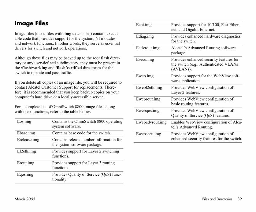
Ma Files and Directories 39
Im
Imabandri
Altorthesw
If coforco
Fowi
E
EE
E
E
E
ort for 10/100, Fast Ether-bit Ethernet.nced hardware diagnostics .anced Routing software
nced security features for g., Authenticated VLANs
ort for the WebView soft-ion.View configuration of es.View configuration of features. View configuration of vice (QoS) features.iew configuration of Alca-
d Routing.View configuration of rity features for the switch.
rch 2005
age Files
age files (those files with .img extensions) contain execut-le code that provides support for the system, NI modules, d network functions. In other words, they serve as essential vers for switch and network operations.
though these files may be backed up to the root flash direc-y or any user-defined subdirectory, they must be present in /flash/working and /flash/certified directories for the itch to operate and pass traffic.
you delete all copies of an image file, you will be required to ntact Alcatel Customer Support for replacements. There-e, it is recommended that you keep backup copies on your mputer’s hard drive or a locally-accessible server.
r a complete list of OmniSwitch 8800 image files, along th their functions, refer to the table below.
os.img Contains the OmniSwitch 8800 operating system software.
base.img Contains base code for the switch.release.img Contains release number information for
the system software package.l2eth.img Provides support for Layer 2 switching
functions.rout.img Provides support for Layer 3 routing
functions.qos.img Provides Quality of Service (QoS) func-
tionality.
Eeni.img Provides suppnet, and Giga
Ediag.img Provides enhafor the switch
Eadvrout.img Alcatel’s Advpackage.
Esecu.img Provides enhathe switch (e.(AVLANs).
Eweb.img Provides suppware applicat
Ewebl2eth.img Provides WebLayer 2 featur
Ewebrout.img Provides Webbasic routing
Ewebqos.img Provides WebQuality of Ser
Ewebadvrout.img Enables WebVtel’s Advance
Ewebsecu.img Provides Webenhanced secu
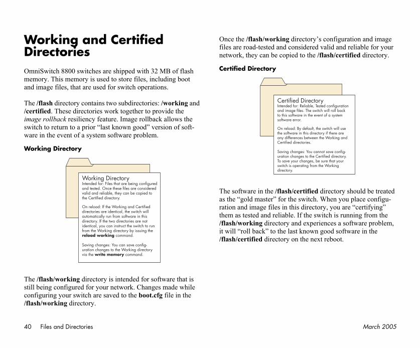
40 March 2005
WDOmmean
Th/ceimswwa
W
Thstico/fl
s configuration and image valid and reliable for your flash/certified directory.
directory should be treated When you place configu-ry, you are “certifying” itch is running from the
iences a software problem, good software in the t reboot.
ry sted configurationch will roll backnt of a system
e switch will useory if there arethe Working and
not save config-ertified directory. sure that your
the Working
Files and Directories
orking and Certified irectoriesniSwitch 8800 switches are shipped with 32 MB of flash
mory. This memory is used to store files, including boot d image files, that are used for switch operations.
e /flash directory contains two subdirectories: /working and rtified. These directories work together to provide the age rollback resiliency feature. Image rollback allows the itch to return to a prior “last known good” version of soft-re in the event of a system software problem.
orking Directory
e /flash/working directory is intended for software that is ll being configured for your network. Changes made while nfiguring your switch are saved to the boot.cfg file in the ash/working directory.
Once the /flash/working directory’files are road-tested and considerednetwork, they can be copied to the /
Certified Directory
The software in the /flash/certified as the “gold master” for the switch. ration and image files in this directothem as tested and reliable. If the sw/flash/working directory and experit will “roll back” to the last known /flash/certified directory on the nex
Working Directory Intended for: Files that are being configuredand tested. Once these files are considered valid and reliable, they can be copied tothe Certified directory. On reload: If the Working and Certifieddirectories are identical, the switch willautomatically run from software in thisdirectory. If the two directories are notidentical, you can instruct the switch to runfrom the Working directory by issuing the reload working command.
Saving changes: You can save config-uration changes to the Working directory via the write memory command.
Certified DirectoIntended for: Reliable, Teand image files. The switto this software in the evesoftware error.
On reload: By default, ththe software in this directany differences between Certified directories.
Saving changes: You canuration changes to the CTo save your changes, beswitch is operating from directory.
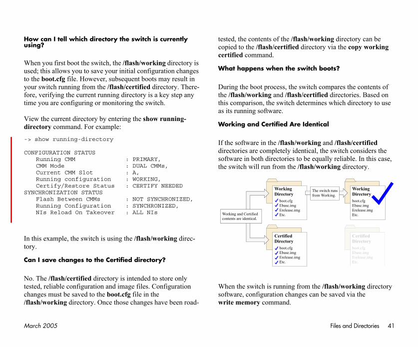
Ma Files and Directories 41
Hous
Wusto yofortim
Vidir
->
CO
SY
In tor
Ca
Notesch/fl
rking directory can be ry via the copy working
boots?
compares the contents of ied directories. Based on nes which directory to use
ical
g and /flash/certified the switch considers the ually reliable. In this case, orking directory.
e /flash/working directory be saved via the
Working Directoryboot.cfgEbase.imgErelease.imgEtc.
Certified Directoryboot.cfgEbase.imgErelease.imgEtc.
switch runsm Working.
rch 2005
w can I tell which directory the switch is currently ing?
hen you first boot the switch, the /flash/working directory is ed; this allows you to save your initial configuration changes the boot.cfg file. However, subsequent boots may result in ur switch running from the /flash/certified directory. There-e, verifying the current running directory is a key step any e you are configuring or monitoring the switch.
ew the current directory by entering the show running-ectory command. For example:
show running-directory
NFIGURATION STATUSRunning CMM : PRIMARY,CMM Mode : DUAL CMMs,Current CMM Slot : A,Running configuration : WORKING,Certify/Restore Status : CERTIFY NEEDED
NCHRONIZATION STATUSFlash Between CMMs : NOT SYNCHRONIZED,Running Configuration : SYNCHRONIZED,NIs Reload On Takeover : ALL NIs
this example, the switch is using the /flash/working direc-y.
n I save changes to the Certified directory?
. The /flash/certified directory is intended to store only ted, reliable configuration and image files. Configuration anges must be saved to the boot.cfg file in the ash/working directory. Once those changes have been road-
tested, the contents of the /flash/wocopied to the /flash/certified directocertified command.
What happens when the switch
During the boot process, the switchthe /flash/working and /flash/certifthis comparison, the switch determias its running software.
Working and Certified Are Ident
If the software in the /flash/workindirectories are completely identical,software in both directories to be eqthe switch will run from the /flash/w
When the switch is running from thsoftware, configuration changes canwrite memory command.
Working Directory
boot.cfgEbase.imgErelease.imgEtc.
Certified Directory
boot.cfgEbase.imgErelease.imgEtc.
Working and Certified contents are identical.
Thefro
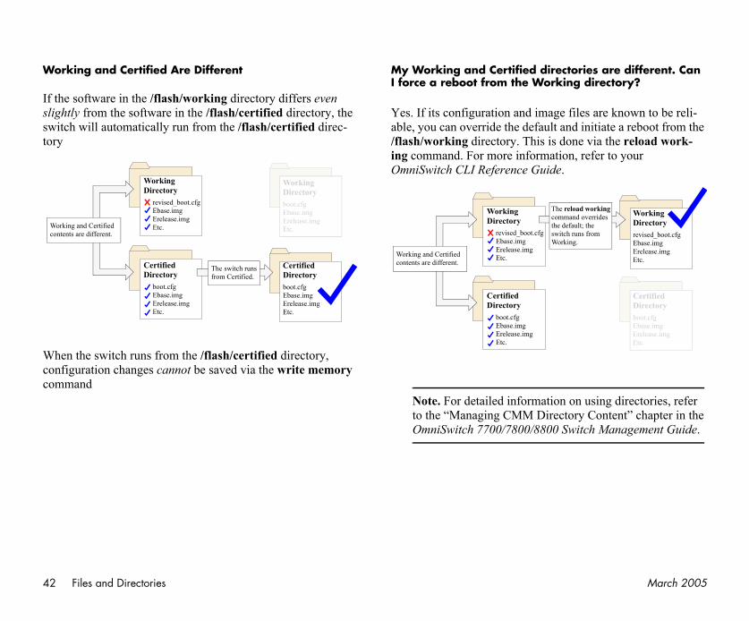
42 March 2005
W
If sliswtor
Wcoco
ories are different. Can g directory?
files are known to be reli-d initiate a reboot from the ne via the reload work-
n, refer to your
on using directories, refer ory Content” chapter in the witch Management Guide.
Wco
Certified Directoryboot.cfgEbase.imgErelease.imgEtc.
Working Directoryrevised_boot.cfgEbase.imgErelease.imgEtc.
load working and overrides fault; the runs from ng.
Files and Directories
orking and Certified Are Different
the software in the /flash/working directory differs even ghtly from the software in the /flash/certified directory, the itch will automatically run from the /flash/certified direc-y
hen the switch runs from the /flash/certified directory, nfiguration changes cannot be saved via the write memory mmand
My Working and Certified directI force a reboot from the Workin
Yes. If its configuration and image able, you can override the default an/flash/working directory. This is doing command. For more informatioOmniSwitch CLI Reference Guide.
Note. For detailed information to the “Managing CMM DirectOmniSwitch 7700/7800/8800 S
Working Directory
revised_boot.cfgEbase.imgErelease.imgEtc.
Certified Directoryboot.cfgEbase.imgErelease.imgEtc.
Certified Directory
boot.cfgEbase.imgErelease.imgEtc.
Working Directoryboot.cfgEbase.imgErelease.imgEtc.orking and Certified
ntents are different.
The switch runsfrom Certified.
Working Directory
revised_boot.cfgEbase.imgErelease.imgEtc.
Certified Directory
boot.cfgEbase.imgErelease.imgEtc.
Working and Certified contents are different.
The recommthe deswitchWorki
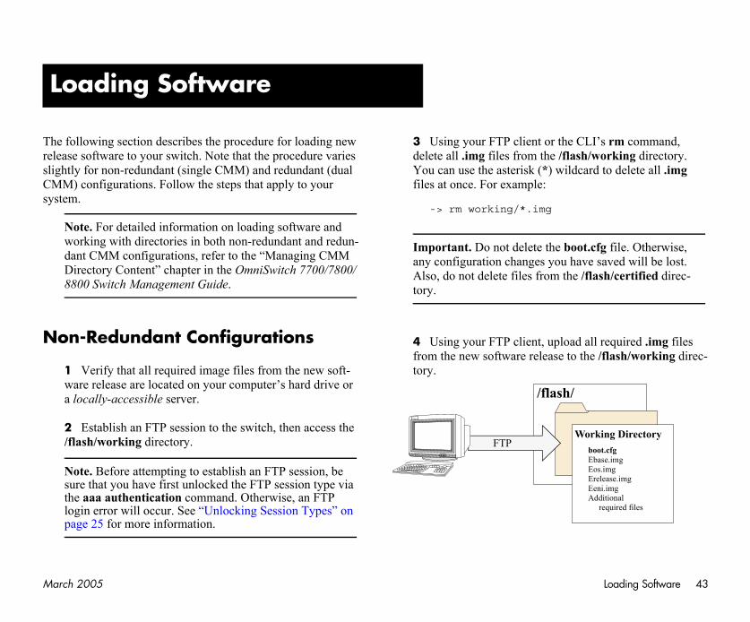
Ma Loading Software 43
ThrelsliCMsy
N
CLI’s rm command, ash/working directory. dcard to delete all .img
oot.cfg file. Otherwise, have saved will be lost. e /flash/certified direc-
ad all required .img files o the /flash/working direc-
L
Working Directoryboot.cfgEbase.imgEos.imgErelease.imgEeni.imgAdditional
required files
/
rch 2005
e following section describes the procedure for loading new ease software to your switch. Note that the procedure varies ghtly for non-redundant (single CMM) and redundant (dual
M) configurations. Follow the steps that apply to your stem.
Note. For detailed information on loading software and working with directories in both non-redundant and redun-dant CMM configurations, refer to the “Managing CMM Directory Content” chapter in the OmniSwitch 7700/7800/8800 Switch Management Guide.
on-Redundant Configurations
1 Verify that all required image files from the new soft-ware release are located on your computer’s hard drive or a locally-accessible server.
2 Establish an FTP session to the switch, then access the /flash/working directory.
Note. Before attempting to establish an FTP session, be sure that you have first unlocked the FTP session type via the aaa authentication command. Otherwise, an FTP login error will occur. See “Unlocking Session Types” on page 25 for more information.
3 Using your FTP client or thedelete all .img files from the /flYou can use the asterisk (*) wilfiles at once. For example:
-> rm working/*.img
Important. Do not delete the bany configuration changes you Also, do not delete files from thtory.
4 Using your FTP client, uplofrom the new software release ttory.
oading Software
/flash
FTP
44 March 2005
tions
solid green and the OK2 he primary and secondary
image files from the new your computer’s hard drive
the switch, then access the
blish an FTP session, be d the FTP session type via nd. Otherwise, an FTP ocking Session Types” on
CLI’s rm command, ash/working directory on ne whether you are logged show running-directory erisk (*) wildcard to delete ple:
oot.cfg file. Otherwise, have saved will be lost. e /flash/certified direc-
Loading Software
5 Use the install command after the software files have been transferred to the switch via FTP. For example:
-> install /flash/working/*.img
Note. For more information on the install command, refer to the OmniSwitch 7700/7800/8800 Switch Management Guide or the OmniSwitch CLI Reference Guide.
6 Reload the switch from the /flash/working directory. To do this, enter
-> reload working no rollback-timeout
at the CLI prompt.
Note. This reload process will take a few moments to complete.
Following the reload, the switch will come up running from the /flash/working directory (i.e., the new release software) until the next system reboot. Meanwhile, the software in the /flash/certified directory remains unchanged and available as a last known good version if an error should occur with the new software.
Once the release software is considered valid and reliable with your network configuration, the contents of the /flash/working directory can be copied to the /flash/certified directory via the copy working certified command.
Redundant Configura
1 Verify that the OK1 LED isLED is flashing green on both tCMM modules.
2 Next, verify that all requiredsoftware release are located on or a locally-accessible server.
3 Establish an FTP session to /flash/working directory.
Note. Before attempting to estasure that you have first unlockethe aaa authentication commalogin error will occur. See “Unlpage 25 for more information.
4 Using your FTP client or thedelete all .img files from the /flthe primary CMM. (To determiinto the primary CMM, use thecommand.) You can use the astall .img files at once. For exam
-> rm working/*.img
Important. Do not delete the bany configuration changes you Also, do not delete files from thtory.

Ma Loading Software 45
M takes over the primary ash/working directory the next system reboot. h/certified directory a last known good version software.
red valid and reliable with tents of the /flash/work-lash/certified directory of g command:
ied flash-synchro
ns. It copies all contents ertified directory on the ctory contents from the M and synchronizes the ffective CMM redundancy.
the copy working nd will take a few
rch 2005
5 Using your FTP client, upload all required .img files from the new software release to the primary CMM’s /flash/working directory.
6 Use the install command after the software files have been transferred to the switch via FTP. For example:
-> install /flash/working/*.img
Note. For more information on the install command, refer to the OmniSwitch 7700/7800/8800 Switch Management Guide or the OmniSwitch CLI Reference Guide.
7 Reload the switch from the /flash/working directory. To do this, enter
-> reload working no rollback-timeout
at the CLI prompt.
Note. This reload process will take a few moments to complete.
During this reload, the secondary CMrole and the switch runs from the /fl(i.e., the new release software) untilMeanwhile, the software in the /flasremains unchanged and available asif an error should occur with the new
Once the release software is consideyour network configuration, the coning directory can be copied to the /feach CMM by entering the followin
-> copy working certif
This command provides two functiofrom /flash/working to the /flash/cprimary CMM, and it copies all direprimary CMM to the secondary CMtwo modules. This helps to ensure e
Note. The process initialized bycertified flash-synchro commamoments to complete.
46 March 2005
ThAlwaad
B
W
•W
•
•S
lowing image files must be ory:
or more information.
U
Using WebView
e switch can be configured and monitored using WebView, catel’s Web-based device management tool. WebView soft-re is pre-installed in the switch; you are not required to load ditional software.
Note. Although WebView software is pre-installed, you must first enable HTTP sessions for your switch before you can log in. Refer to “Unlocking Session Types” on page 25 for more information.
rowser Compatibility
ebView has been tested on the following Web browsers:
Internet Explorer 6.0 for Windows 2000, Windows NT, indows XP
Netscape 4.79 for Solaris 2.8, HP-UX 11.0
Netscape 7.1 for Windows 2000, Windows NT, olaris 2.8
Required Image Files
In order to access WebView, the folpresent in the current running direct
• Eweb.img
• Ewebl2eth.img
• Ewebrout.img
• Ewebqos.img
• Ewebadvrout.img
• Ewebsecu.img
Refer to “Image Files” on page 39 f
sing WebView
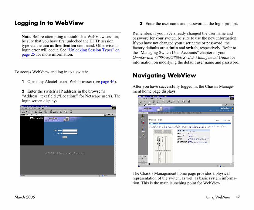
Ma Using WebView 47
Lo
To
sword at the login prompt.
nged the user name and use the new information. ame or password, the ch, respectively. Refer to ts” chapter of your Management Guide for
lt user name and password.
in, the Chassis Manage-
e provides a physical as basic system informa-nt for WebView.
rch 2005
gging In to WebView
Note. Before attempting to establish a WebView session, be sure that you have first unlocked the HTTP session type via the aaa authentication command. Otherwise, a login error will occur. See “Unlocking Session Types” on page 25 for more information.
access WebView and log in to a switch:
1 Open any Alcatel-tested Web browser (see page 46).
2 Enter the switch’s IP address in the browser’s “Address” text field (“Location:” for Netscape users). The login screen displays:
3 Enter the user name and pas
Remember, if you have already chapassword for your switch, be sure toIf you have not changed your user nfactory defaults are admin and switthe “Managing Switch User AccounOmniSwitch 7700/7800/8800 Switchinformation on modifying the defau
Navigating WebView
After you have successfully logged ment home page displays:
The Chassis Management home pagrepresentation of the switch, as welltion. This is the main launching poi
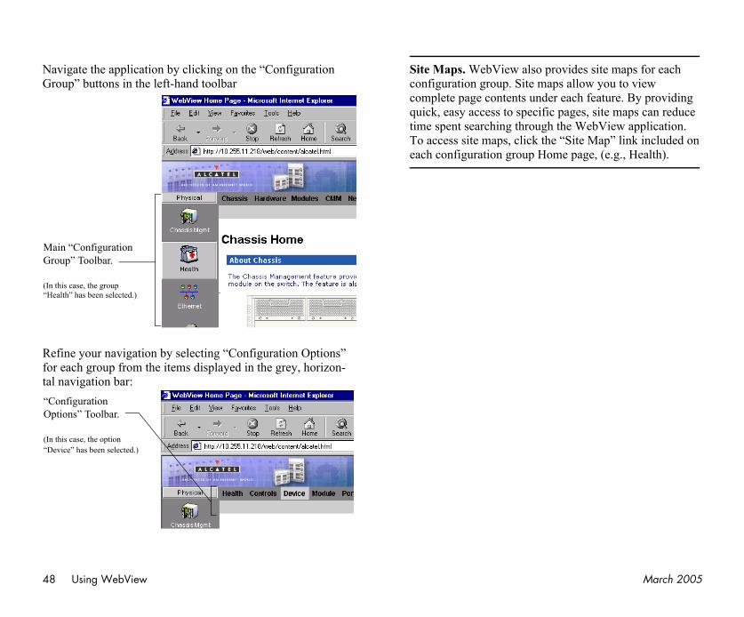
48 March 2005
NaGr
Refortal
ides site maps for each allow you to view ach feature. By providing ages, site maps can reduce e WebView application. Site Map” link included on page, (e.g., Health).
MaGr
(In “He
“COp
(In “De
Using WebView
vigate the application by clicking on the “Configuration oup” buttons in the left-hand toolbar
fine your navigation by selecting “Configuration Options” each group from the items displayed in the grey, horizon- navigation bar:
Site Maps. WebView also provconfiguration group. Site maps complete page contents under equick, easy access to specific ptime spent searching through thTo access site maps, click the “each configuration group Home
in “Configuration oup” Toolbar.
this case, the group alth” has been selected.)
onfiguration tions” Toolbar.
this case, the optionvice” has been selected.)
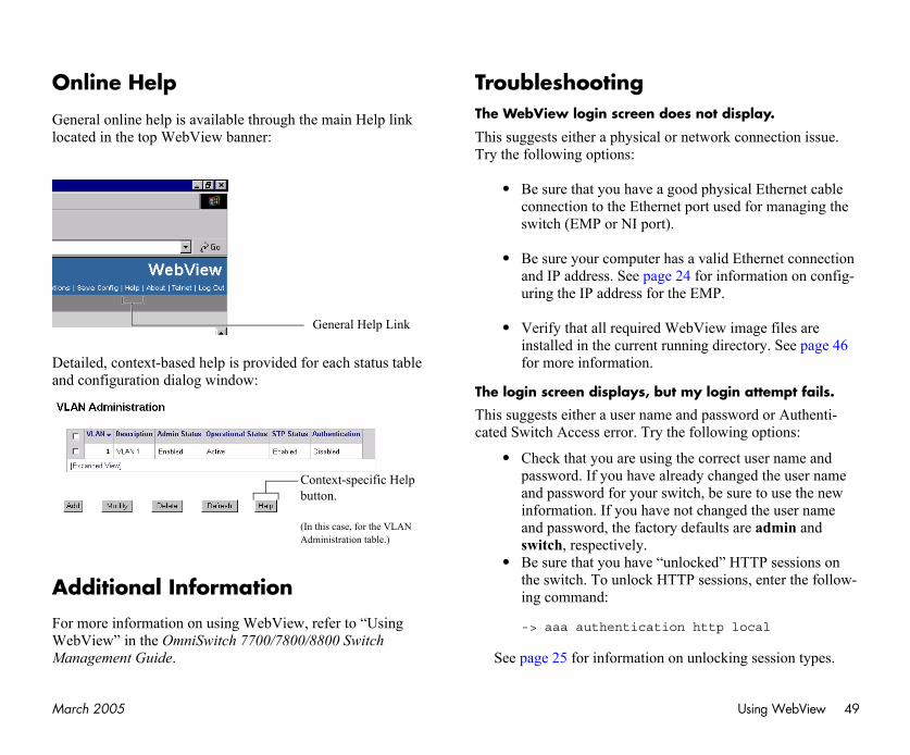
Ma Using WebView 49
O
Geloc
Dean
A
FoWMa
not display.
twork connection issue.
d physical Ethernet cable ort used for managing the
valid Ethernet connection for information on config-EMP.
View image files are ng directory. See page 46
y login attempt fails.
d password or Authenti-ollowing options:
correct user name and y changed the user name h, be sure to use the new changed the user name faults are admin and
cked” HTTP sessions on sessions, enter the follow-
http local
nlocking session types.
rch 2005
nline Help
neral online help is available through the main Help link ated in the top WebView banner:
tailed, context-based help is provided for each status table d configuration dialog window:
dditional Information
r more information on using WebView, refer to “Using ebView” in the OmniSwitch 7700/7800/8800 Switch nagement Guide.
TroubleshootingThe WebView login screen does
This suggests either a physical or neTry the following options:
• Be sure that you have a gooconnection to the Ethernet pswitch (EMP or NI port).
• Be sure your computer has aand IP address. See page 24uring the IP address for the
• Verify that all required Webinstalled in the current runnifor more information.
The login screen displays, but m
This suggests either a user name ancated Switch Access error. Try the f
• Check that you are using thepassword. If you have alreadand password for your switcinformation. If you have notand password, the factory deswitch, respectively.
• Be sure that you have “unlothe switch. To unlock HTTPing command:
-> aaa authentication
See page 25 for information on u
General Help Link
Context-specific Help button.
(In this case, for the VLAN Administration table.)
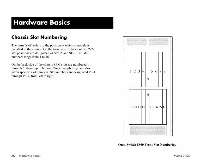
50 March 2005
C
Thinsslonu
Onthrgivthr
Slot Numbering
H
1415 16
6 7 8
Hardware Basics
hassis Slot Numbering
e term “slot” refers to the position at which a module is talled in the chassis. On the front side of the chassis, CMM t positions are designated as Slot A and Slot B. NI slot mbers range from 1 to 16.
the back side of the chassis SFM slots are numbered 1 ough 5, from top to bottom. Power supply bays are also en specific slot numbers. Slot numbers are designated PS-1 ough PS-4, from left to right.
OmniSwitch 8800 Front
ardware Basics
A
B
1 2 3 4
139 10 1112
5

Ma Hardware Basics 51
ment
CMM) is the management . In its role as the manage-ystem services, including:
net management port
management, including the LI)
ebView)
es, including redundancy ith another CMM) and
rch 2005
OmniSwitch 8800 Back Slot Numbering
Chassis ManageModule (CMM)The Chassis Management Module (unit for OmniSwitch 8800 switchesment unit, the CMM provides key s
• Console, modem, and Etherconnections to the switch
• Software and configuration Command Line Interface (C
• Web-based management (W
• SNMP management
• Power management
• Temperature management
• Switch diagnostics
• Important availability featur(when used in conjunction wimage rollback.
1
5
4
3
2
PS1 PS2 PS3 PS4
PS-1 PS-2 PS-3 PS-4
12345
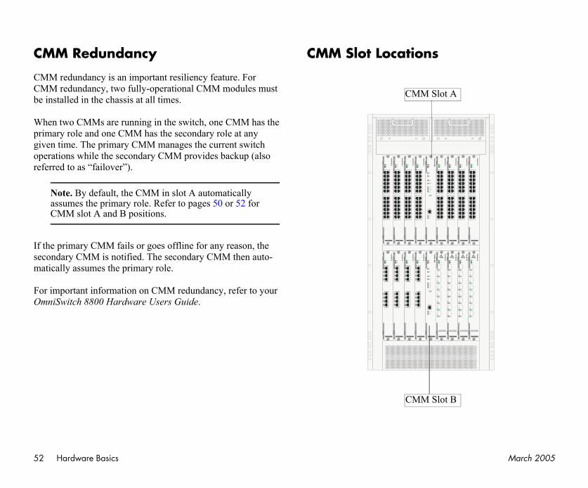
52 March 2005
C
CMCMbe
Wprigivopref
If secma
FoOm
OS
-GN
I-U8
LINK
ACT
LINK
ACT
LINK
ACT
LINK
ACT
LINK
ACT
LINK
ACT
LINK
ACT
LINK
ACT
8
7
6
5
4
3
2
1
OK1
OK2
OS
-GN
I-U8
LINK
ACT
LINK
ACT
LINK
ACT
LINK
ACT
LINK
ACT
LINK
ACT
LINK
ACT
LINK
ACT
8
7
6
5
4
3
2
1
OK1
OK2
OS
-GN
I-U8
LINK
ACT
LINK
ACT
LINK
ACT
LINK
ACT
LINK
ACT
LINK
ACT
LINK
ACT
LINK
ACT
8
7
6
5
4
3
2
1
OK1
OK2
OS
-EN
I-C24
1
2
12
14
3
5
7
9
11
13
15
17
19
21
23
OK1
OK2
24
OS
-EN
I-C24
1
2
12
14
3
5
7
9
11
13
15
17
19
21
23
OK1
OK2
24
OS
-EN
I-C24
1
2
12
14
3
5
7
9
11
13
15
17
19
21
23
OK1
OK2
24
A
B
Hardware Basics
MM Redundancy
M redundancy is an important resiliency feature. For M redundancy, two fully-operational CMM modules must
installed in the chassis at all times.
hen two CMMs are running in the switch, one CMM has the mary role and one CMM has the secondary role at any en time. The primary CMM manages the current switch
erations while the secondary CMM provides backup (also erred to as “failover”).
Note. By default, the CMM in slot A automatically assumes the primary role. Refer to pages 50 or 52 for CMM slot A and B positions.
the primary CMM fails or goes offline for any reason, the ondary CMM is notified. The secondary CMM then auto-tically assumes the primary role.
r important information on CMM redundancy, refer to your niSwitch 8800 Hardware Users Guide.
CMM Slot Locations
OS
-GN
I-C8
1
2
3
4
5
6
7
8
ACT
LINK
ACT
LINK
ACT
LINK
ACT
LINK
ACT
LINK
ACT
LINK
ACT
LINK
ACT
LINK
OK1
OK2
OS
-GN
I-C8
1
2
3
4
5
6
7
8
ACT
LINK
ACT
LINK
ACT
LINK
ACT
LINK
ACT
LINK
ACT
LINK
ACT
LINK
ACT
LINK
OK1
OK2
OS
-GN
I-C8
1
2
3
4
5
6
7
8
ACT
LINK
ACT
LINK
ACT
LINK
ACT
LINK
ACT
LINK
ACT
LINK
ACT
LINK
ACT
LINK
OK1
OK2
OS
-GN
I-C8
1
2
3
4
5
6
7
8
ACT
LINK
ACT
LINK
ACT
LINK
ACT
LINK
ACT
LINK
ACT
LINK
ACT
LINK
ACT
LINK
OK1
OK2
OS
-GN
I-U8
LINK
ACT
LINK
ACT
LINK
ACT
LINK
ACT
LINK
ACT
LINK
ACT
LINK
ACT
LINK
ACT
8
7
6
5
4
3
2
1
OK1
OK2
OS
8800-C
MMOK1
OK2
PRI
SEC
TEMP
FAN
STATUS
CONSOLE
/ MODEM
1
2
3
ACT
LINK
ENET
OS
-EN
I-C24
1
2
12
14
3
5
7
9
11
13
15
17
19
21
23
OK1
OK2
24
OS
-EN
I-C24
1
2
12
14
3
5
7
9
11
13
15
17
19
21
23
OK1
OK2
24
OS
-EN
I-C24
1
2
12
14
3
5
7
9
11
13
15
17
19
21
23
OK1
OK2
24
OS
-EN
I-C24
1
2
12
14
3
5
7
9
11
13
15
17
19
21
23
OK1
OK2
24
OS
-EN
I-C24
1
2
12
14
3
5
7
9
11
13
15
17
19
21
23
OK1
OK2
24
OS
8800-C
MMOK1
OK2
PRI
SEC
TEMP
FAN
STATUS
CONSOLE
/ MODEM
1
2
3
ACT
LINK
ENET
CMM Slot
CMM Slot
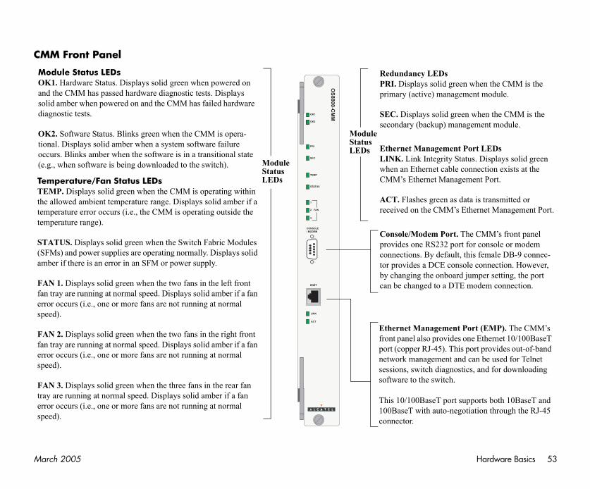
Ma Hardware Basics 53
CM
rt. The CMM’s front panel port for console or modem ult, this female DB-9 connec-
console connection. However, oard jumper setting, the port DTE modem connection.
ent Port (EMP). The CMM’s ides one Ethernet 10/100BaseT This port provides out-of-band t and can be used for Telnet nostics, and for downloading h.
ort supports both 10BaseT and negotiation through the RJ-45
ent Port LEDsy Status. Displays solid green ble connection exists at the nagement Port.
as data is transmitted or ’s Ethernet Management Port.
MOansod
Otio(e
green when the CMM is the agement module.
green when the CMM is the management module.
TeTthtete
ST(Sam
Ffaersp
Ffaersp
Ftrersp
rch 2005
M Front Panel
OS
8800-C
MMOK1
OK2
PRI
SEC
TEMP
FAN
STATUS
CONSOLE
/ MODEM
1
2
3
ACT
LINK
ENET
Console/Modem Poprovides one RS232connections. By defator provides a DCE by changing the onbcan be changed to a
Ethernet Managemfront panel also provport (copper RJ-45). network managemensessions, switch diagsoftware to the switc
This 10/100BaseT p100BaseT with auto-connector.
Ethernet ManagemLINK. Link Integritwhen an Ethernet caCMM’s Ethernet Ma
ACT. Flashes greenreceived on the CMM
odule Status LEDsK1. Hardware Status. Displays solid green when powered on d the CMM has passed hardware diagnostic tests. Displays lid amber when powered on and the CMM has failed hardware
iagnostic tests.
K2. Software Status. Blinks green when the CMM is opera-onal. Displays solid amber when a system software failure ccurs. Blinks amber when the software is in a transitional state .g., when software is being downloaded to the switch).
Redundancy LEDsPRI. Displays solid primary (active) man
SEC. Displays solidsecondary (backup)
mperature/Fan Status LEDsEMP. Displays solid green when the CMM is operating within e allowed ambient temperature range. Displays solid amber if a mperature error occurs (i.e., the CMM is operating outside the mperature range).
ATUS. Displays solid green when the Switch Fabric Modules FMs) and power supplies are operating normally. Displays solid ber if there is an error in an SFM or power supply.
AN 1. Displays solid green when the two fans in the left front n tray are running at normal speed. Displays solid amber if a fan ror occurs (i.e., one or more fans are not running at normal eed).
AN 2. Displays solid green when the two fans in the right front n tray are running at normal speed. Displays solid amber if a fan ror occurs (i.e., one or more fans are not running at normal eed).
AN 3. Displays solid green when the three fans in the rear fan ay are running at normal speed. Displays solid amber if a fan ror occurs (i.e., one or more fans are not running at normal eed).
ModuleStatusLEDs
ModuleStatusLEDs
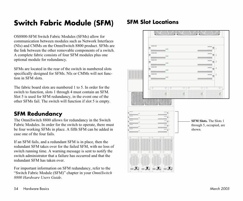
54 March 2005
S
OSco(NtheA op
SFsptio
ThswSlooth
SFThFabeca
If redswswred
Fo“S88
AC OK
DC OK
TEMPFAIL
AC OK
DC OK
TEMPFAIL
OK
OK
MPIL
1
5
4
3
2
SFM Slots. The Slots 1 through 5, occupied, are shown.
Hardware Basics
witch Fabric Module (SFM)
8800-SFM Switch Fabric Modules (SFMs) allow for mmunication between modules such as Network Interfaces Is) and CMMs on the OmniSwitch 8800 product. SFMs are link between the other removable components of a switch. complete fabric consists of four SFM modules plus one tional module for redundancy.
Ms are located in the rear of the switch in numbered slots ecifically designed for SFMs. NIs or CMMs will not func-n in SFM slots.
e fabric board slots are numbered 1 to 5. In order for the itch to function, slots 1 through 4 must contain an SFM. t 5 is used for SFM redundancy, in the event one of the er SFMs fail. The switch will function if slot 5 is empty.
M Redundancye OmniSwitch 8800 allows for redundancy in the Switch bric Modules. In order for the switch to operate, there must four working SFMs in place. A fifth SFM can be added in se one of the four fails.
an SFM fails, and a redundant SFM is in place, then the undant SFM takes over for the failed SFM, with no loss of itch running time. A warning message is sent to notify the itch administrator that a failure has occurred and that the undant SFM has taken over.
r important information on SFM redundancy, refer to the witch Fabric Module (SFM)” chapter in your OmniSwitch 00 Hardware Users Guide.
SFM Slot Locations
OS8800-SFM
OK1 OK2
OS8800-SFM
OK1 OK2
OS8800-SFM
OK1 OK2
OS8800-SFM
OK1 OK2
OS8800-SFM
OK1 OK2
50/60Hz, 8.0 A230V
AC OK
DC OK
TEMPFAIL
!CAUTION: THIS UNIT MAY BE EQUIPPED
WITH FOUR POWER SUPPLIE CORDS. TO REDUCETHE RISK OF ELECTRICAL SHOCK, DISCONNECTALL POWER SUPPLY CORDS BEFORESERVICING UNIT.
ATTENTION: CET APPAREIL COMPORTE
PLUS D'UN CORDON D'ALIMENTATION. AFIN DEPREVENIR LES CHOCS ELECTRIQUES, DEBRANCHETOUS LES CORDONS D'ALIMENTATION AVANTE DEFAIRE LA REPARATION.
1
5
4
3
2
OS8800-SFM
OK1 OK2
OS8800-SFM
OK1 OK2
OS8800-SFM
OK1 OK2
OS8800-SFM
OK1 OK2
OS8800-SFM
OK1 OK2
AC
DC
TEFA
AC OK
DC OK
TEMPFAIL
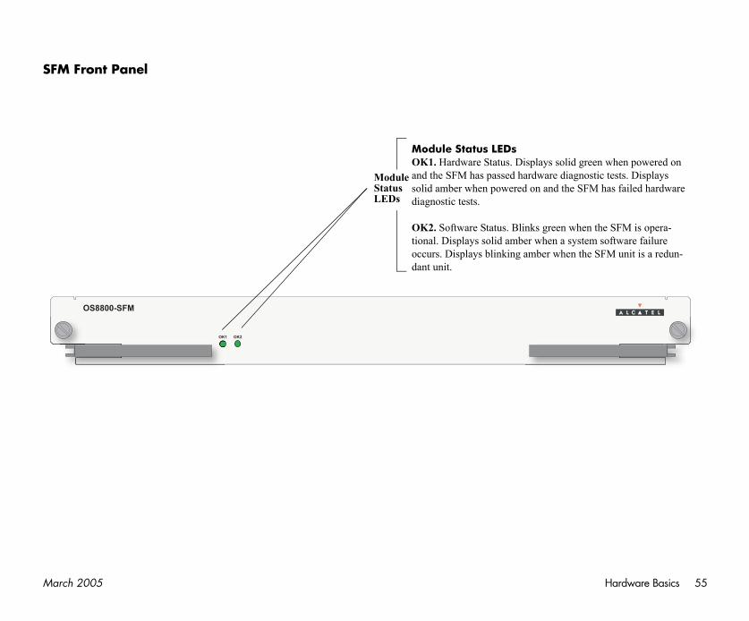
Ma Hardware Basics 55
SF
id green when powered on agnostic tests. Displays e SFM has failed hardware
when the SFM is opera-ystem software failure n the SFM unit is a redun-
rch 2005
M Front Panel
OK1 OK2
OS8800-SFM
Module Status LEDsOK1. Hardware Status. Displays soland the SFM has passed hardware disolid amber when powered on and thdiagnostic tests.
OK2. Software Status. Blinks green tional. Displays solid amber when a soccurs. Displays blinking amber whedant unit.
ModuleStatusLEDs
56 March 2005
NMThNedeGNOSHa
EN
Etcotio
G
Thpromoin meco
re-rate twisted-pair 1 Gbps
high-density 1 Gbps Mini-ors.
high-density twisted-pair
ce Converters
8 Miniature Gigabit Inter-nd the OS8-GNI-U24 iGBIC is a Gigabit Ether-e—i.e., it can be installed ed on and operating with-BIC module or the host
switch automatically gath- the connector’s serial n includes the Mini-
aces, manufacturer, and
Hardware Basics
etwork Interface (NI) odules
e following section outlines front panel information for twork Interface (NI) modules, including LED and port scriptions. For detailed information on OS8-ENI-C24, OS8-I-U8, OS8-GNI-C8, OS8-GNI-U24, OS8-GNI-C24, and 8-10GNI-UR1 modules, refer to your OmniSwitch 8800 rdware Users Guide.
I Modules
hernet Network Interface (ENI) modules provide Ethernet nnectivity and are available in the following port configura-n:
• OS8-ENI-C24. Provides 24 twisted-pair RJ-45 ports, auto-negotiating and individually configurable as 10BaseT or 100BaseTX.
NI Modules
e Gigabit Ethernet Network Interface (GNI) module vides up to eight 1000 Mbps (1 Gbps) connections per dule. GNI modules can be used for backbone connections networks where Gigabit Ethernet is used as the backbone dia. GNI modules can also be used in the wiring closet for
nnections to workstations and other devices.
• OS8-GNI-U8. Provides 8 wire-rate 1 Gbps MiniGBIC ports that use LC connectors.
• OS8-GNI-C8. Provides 8 wiRJ-45 ports.
• OS8-GNI-U24. Provides 24 GBIC ports that use LC connect
• OS8-GNI-C24. Provides 24 10/100/1000 Mbps RJ-45 ports.
Miniature Gigabit Interfa(MiniGBICs)
The OS8-GNI-U8 module providesface Converters (MiniGBIC) slots aprovides 24 MiniGBIC slots. A Minnet port module that is hot-pluggablor removed while the GNI is powerout the risk of damage to the MiniGcircuitry.
When a MiniGBIC is installed, the ers basic MiniGBIC information viaEEPROM interface. This informatioGBIC’s capabilities, standard interfother information.
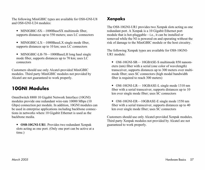
Ma Hardware Basics 57
Than
CumoAl
1
OmmoGbbetioba
Xenpak slots acting as one igabit Ethernet port it can be installed or and operating without the dule or the host circuitry.
ilable for OS8-10GNI-
-S multimode 850 nanom-e color of wavelength) p to 300 meters over multi-(high modal bandwidth ters)
-L single mode 1310 nm pports distances up to 10 SC connectors
-E single mode 1550 nm pports distances up to 40 SC connectors
provided Xenpak modules. vided by Alcatel are not
rch 2005
e following MiniGBIC types are available for OS8-GNI-U8 d OS8-GNI-U24 modules:
• MINIGBIC-SX—1000BaseSX multimode fiber, supports distances up to 550 meters; uses LC connectors
• MINIGBIC-LX—1000BaseLX single mode fiber, supports distances up to 10 km; uses LC connectors
• MINIGBIC-LH-70—1000BaseLH long haul single mode fiber, supports distances up to 70 km; uses LC connectors
stomers should use only Alcatel-provided MiniGBIC dules. Third party MiniGBIC modules not provided by
catel are not guaranteed to work properly.
0GNI Modules
niSwitch 8800 10 Gigabit Network Interface (10GNI) dules provide one redundant wire-rate 10000 Mbps (10 ps) connection per module. In addition, 10GNI modules can
used in enterprise applications including backbone connec-ns in networks where 10 Gigabit Ethernet is used as the ckbone media.
• OS8-10GNI-UR1. Provides two redundant Xenpak slots acting as one port. (Only one port can be active at a time.)
Xenpaks
The OS8-10GNI-UR1 provides tworedundant port. A Xenpak is a 10 Gmodule that is hot-pluggable—i.e., removed while the NI is powered onrisk of damage to the MiniGBIC mo
The following Xenpak types are avaUR1 module:
• OM-10GNI-SR— 10GBASEeters (nm) fiber with a serial (ontransceiver, supports distances umode fiber; uses SC connectors fiber is required to reach 300 me
• OM-10GNI-LR— 10GBASEfiber with a serial transceiver, sukm over single mode fiber; uses
• OM-10GNI-ER—10GBASEfiber with a serial transceiver, sukm over single mode fiber; uses
Customers should use only Alcatel-Third party Xenpak modules not proguaranteed to work properly.
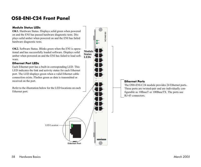
58 March 2005
O
MOonplha
OtioamwEtEaLEpocore
ReEt
le provides 24 Ethernet ports. air and are individually con-
100BaseTX. The ports use
Hardware Basics
S8-ENI-C24 Front Panel
OS
-EN
I-C24
1
2
12
14
3
5
7
9
11
13
15
17
19
21
23
OK1
OK2
24
odule Status LEDsK1. Hardware Status. Displays solid green when powered and the ENI has passed hardware diagnostic tests. Dis-ays solid amber when powered on and the ENI has failed rdware diagnostic tests.
K2. Software Status. Blinks green when the ENI is opera-nal and has successfully loaded software. Displays solid ber when powered on and the ENI has failed to load soft-
are.hernet Port LEDsch Ethernet port has a built-in corresponding LED. This D indicates the link and activity status for each Ethernet rt. The LED displays green when a valid Ethernet cable nnection exists. Flashes green as data is transmitted or ceived on the port.
fer to the illustration below for the LED locations on each hernet port.
Ethernet PortsThe OS8-ENI-C24 moduThese ports are twisted-pfigurable as 10BaseT or RJ-45 connectors.
Ethernet Port
LED Location
ModuleStatusLEDs

Ma Hardware Basics 59
O
le provides eight (8) Mini-upport the following Mini-
000BaseSX multimode fiber, up to 550 meters; uses LC
000BaseLX single mode ances up to 10 km; uses LC
—1000BaseLH long haul ances up to 70 km; uses LC
h 8800 Hardware Users proper handling of LC con-ble.
rch 2005
S8-GNI-U8 Front Panel
OS
-GN
I-U8
LINK
ACT
LINK
ACT
LINK
ACT
LINK
ACT
LINK
ACT
LINK
ACT
LINK
ACT
LINK
ACT
8
7
6
5
4
3
2
1
OK1
OK2
Module Status LEDsOK1. Hardware Status. Displays solid green when powered on and the GNI has passed hardware diagnostic tests. Displays solid amber when powered on and the GNI has failed hardware diagnostic tests.
OK2. Software Status. Blinks green when the GNI is operational and has successfully loaded software. Displays solid amber when powered on and the GNI has failed to load software.
Gigabit Ethernet Port LEDsACT. Activity Status. Flashes green when data is transmitted or received on the corre-sponding Gigabit Ethernet port.
LINK. Link Integrity Status. Displays solid green when a fiber cable connection exists at the corresponding Gigabit Ethernet port.
Gigabit Ethernet PortsThe OS8-GNI-U8 moduGBIC slots. These slots sGBIC types:
• MINIGBIC-SX—1supports distances connectors
• MINIGBIC-LX—1fiber, supports distconnectors
• MINIGBIC-LH-70fiber, supports distconnectors.
ModuleStatusLEDs
NoteRefer to your OmniSwitcGuide for information onnectors and fiber-optic ca
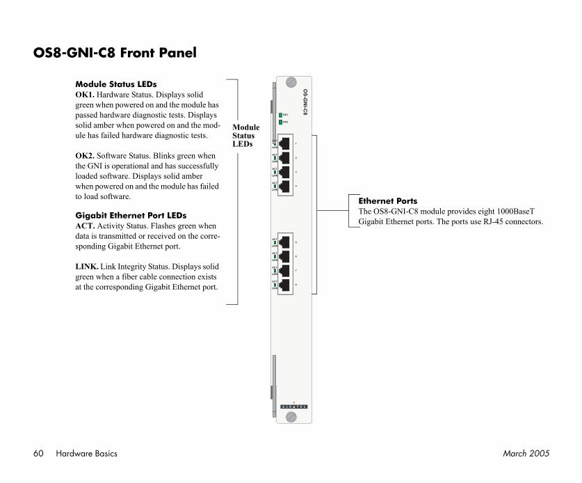
60 March 2005
O
e provides eight 1000BaseT he ports use RJ-45 connectors.
Hardware Basics
S8-GNI-C8 Front Panel
OS
-GN
I-C8
1
2
3
4
5
6
7
8
ACT
LINK
ACT
LINK
ACT
LINK
ACT
LINK
ACT
LINK
ACT
LINK
ACT
LINK
ACT
LINK
OK1
OK2
Module Status LEDsOK1. Hardware Status. Displays solid green when powered on and the module has passed hardware diagnostic tests. Displays solid amber when powered on and the mod-ule has failed hardware diagnostic tests.
OK2. Software Status. Blinks green when the GNI is operational and has successfully loaded software. Displays solid amber when powered on and the module has failed to load software. Ethernet Ports
The OS8-GNI-C8 modulGigabit Ethernet ports. T
ModuleStatusLEDs
Gigabit Ethernet Port LEDsACT. Activity Status. Flashes green when data is transmitted or received on the corre-sponding Gigabit Ethernet port.
LINK. Link Integrity Status. Displays solid green when a fiber cable connection exists at the corresponding Gigabit Ethernet port.
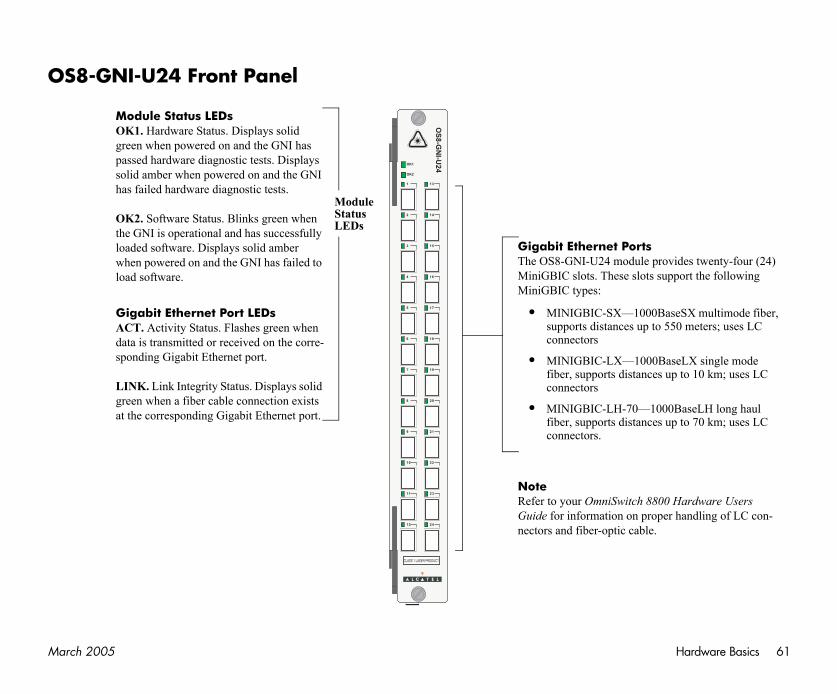
Ma Hardware Basics 61
O
rtsule provides twenty-four (24) lots support the following
000BaseSX multimode fiber, up to 550 meters; uses LC
000BaseLX single mode ances up to 10 km; uses LC
—1000BaseLH long haul ances up to 70 km; uses LC
h 8800 Hardware Users proper handling of LC con-ble.
rch 2005
S8-GNI-U24 Front Panel
OS
8-G
NI-U
24
OK1
OK2
1 13
2 14
3 15
4 16
5 17
6 18
7 19
8 20
9 21
10 22
11 23
12 24
Module Status LEDsOK1. Hardware Status. Displays solid green when powered on and the GNI has passed hardware diagnostic tests. Displays solid amber when powered on and the GNI has failed hardware diagnostic tests.
OK2. Software Status. Blinks green when the GNI is operational and has successfully loaded software. Displays solid amber when powered on and the GNI has failed to load software.
Gigabit Ethernet Port LEDsACT. Activity Status. Flashes green when data is transmitted or received on the corre-sponding Gigabit Ethernet port.
LINK. Link Integrity Status. Displays solid green when a fiber cable connection exists at the corresponding Gigabit Ethernet port.
Gigabit Ethernet PoThe OS8-GNI-U24 modMiniGBIC slots. These sMiniGBIC types:
• MINIGBIC-SX—1supports distances connectors
• MINIGBIC-LX—1fiber, supports distconnectors
• MINIGBIC-LH-70fiber, supports distconnectors.
ModuleStatusLEDs
NoteRefer to your OmniSwitcGuide for information onnectors and fiber-optic ca
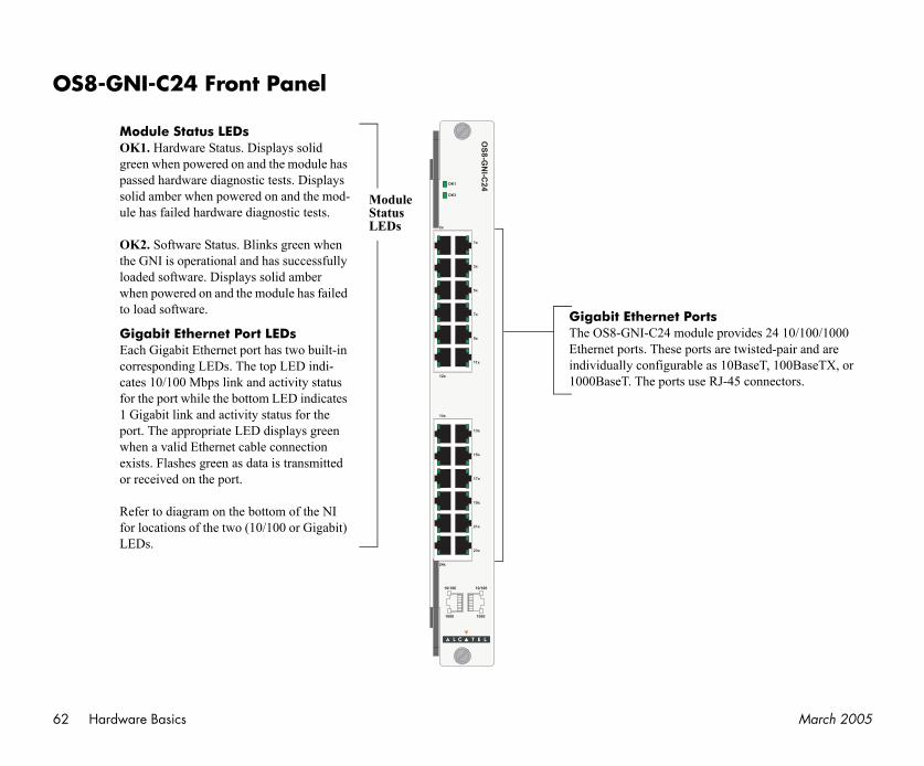
62 March 2005
O
tsle provides 24 10/100/1000 ts are twisted-pair and are as 10BaseT, 100BaseTX, or RJ-45 connectors.
Hardware Basics
S8-GNI-C24 Front Panel
OS
8-G
NI-C
24OK1
OK2
2x
12x
1x
3x
5x
7x
9x
11x
14x
24x
13x
15x
17x
19x
21x
23x
10/100 10/100
10001000
Module Status LEDsOK1. Hardware Status. Displays solid green when powered on and the module has passed hardware diagnostic tests. Displays solid amber when powered on and the mod-ule has failed hardware diagnostic tests.
OK2. Software Status. Blinks green when the GNI is operational and has successfully loaded software. Displays solid amber when powered on and the module has failed to load software. Gigabit Ethernet Por
The OS8-GNI-C24 moduEthernet ports. These porindividually configurable1000BaseT. The ports use
ModuleStatusLEDs
Gigabit Ethernet Port LEDsEach Gigabit Ethernet port has two built-in corresponding LEDs. The top LED indi-cates 10/100 Mbps link and activity status for the port while the bottom LED indicates 1 Gigabit link and activity status for the port. The appropriate LED displays green when a valid Ethernet cable connection exists. Flashes green as data is transmitted or received on the port.
Refer to diagram on the bottom of the NI for locations of the two (10/100 or Gigabit) LEDs.
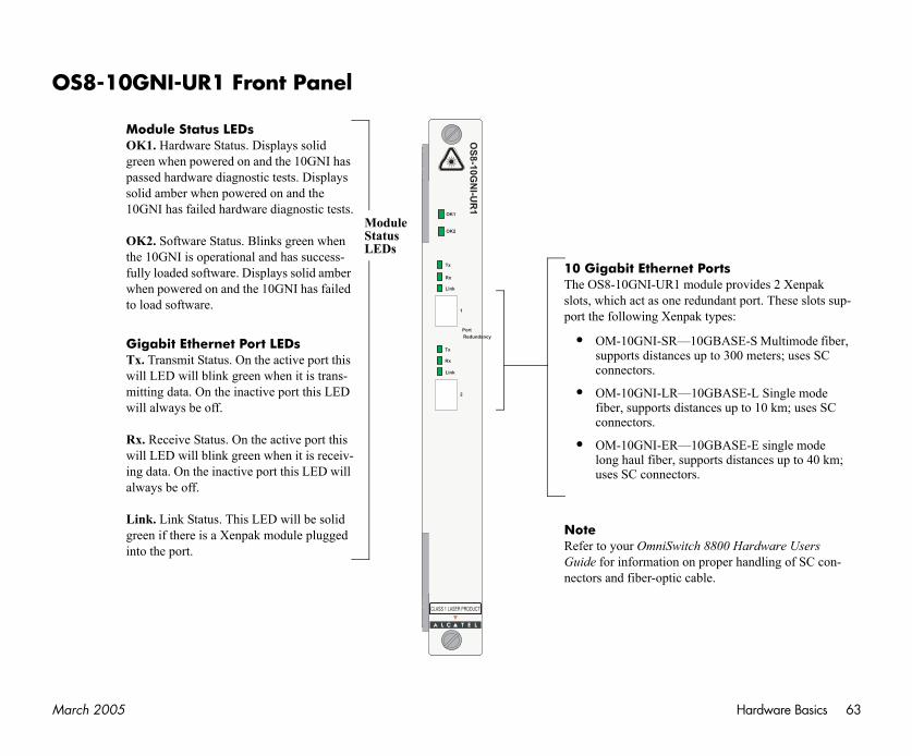
Ma Hardware Basics 63
O
Portsodule provides 2 Xenpak dundant port. These slots sup-k types:
0GBASE-S Multimode fiber, up to 300 meters; uses SC
0GBASE-L Single mode ances up to 10 km; uses SC
0GBASE-E single mode ports distances up to 40 km;
s.
h 8800 Hardware Users proper handling of SC con-ble.
rch 2005
S8-10GNI-UR1 Front Panel
1
2
OS
8-1
0G
NI-U
R1
OK2
OK1
Link
Link
Tx
Rx
Rx
Tx
Port
Redundancy
Module Status LEDsOK1. Hardware Status. Displays solid green when powered on and the 10GNI has passed hardware diagnostic tests. Displays solid amber when powered on and the 10GNI has failed hardware diagnostic tests.
OK2. Software Status. Blinks green when the 10GNI is operational and has success-fully loaded software. Displays solid amber when powered on and the 10GNI has failed to load software.
Gigabit Ethernet Port LEDsTx. Transmit Status. On the active port this will LED will blink green when it is trans-mitting data. On the inactive port this LED will always be off.
Rx. Receive Status. On the active port this will LED will blink green when it is receiv-ing data. On the inactive port this LED will always be off.
Link. Link Status. This LED will be solid green if there is a Xenpak module plugged into the port.
10 Gigabit EthernetThe OS8-10GNI-UR1 mslots, which act as one report the following Xenpa
• OM-10GNI-SR—1supports distances connectors.
• OM-10GNI-LR—1fiber, supports distconnectors.
• OM-10GNI-ER—1long haul fiber, supuses SC connector
ModuleStatusLEDs
NoteRefer to your OmniSwitcGuide for information onnectors and fiber-optic ca
64 March 2005
Thcofol
0 Switch Management
ying an individual switch k. Topics include the soft-image rollback protec-ccess, managing switch using SNMP, and using WebView).
0 Network Configuration
ion procedures and ll the major software ed in the base software
yer 2 information (Ether-), Layer 3 information IP and IPX), security
Ns), Quality of Service server load balancing.
U
User Documentation on CD
e CD that accompanies this Getting Started Guide contains mprehensive Alcatel user documentation, including the lowing manuals:
• OmniSwitch 8800 Getting Started Guide
Describes the hardware and software procedures for getting an OmniSwitch 8800 up and running. Also provides information on fundamental aspects of OmniSwitch hardware components and software archi-tecture.
• OmniSwitch 8800 Hardware Users Guide
Complete technical specifications and procedures for all OmniSwitch 8800 chassis, power supplies, fans, Chassis Management Modules (CMMs), Switch Fabric Modules (SFMs), and Network Interface (NI) modules.
• OmniSwitch CLI Reference Guide
Complete reference to all CLI commands supported on the OmniSwitch 8800. Includes syntax definitions, default values, examples, usage guidelines, and CLI-to-MIB variable mappings.
• OmniSwitch 7700/7800/880Guide
Includes procedures for readfor integration into a networware directory architecture, tions, authenticated switch afiles, system configuration, web management software (
• OmniSwitch 7700/7800/880Guide
Includes network configuratdescriptive information on afeatures and protocols includpackage. Chapters cover Lanet and VLAN configuration(routing protocols, such as Roptions (authenticated VLA(QoS), link aggregation, and
ser Documentation on CD

Ma er Documentation on CD 65
G
Toins
AlAcwa
Tosea
e document image behind global search feature is not
eader you are currently
pages from the documen-ge if it is selected in your ay print with slightly
rch 2005 Us
• OmniSwitch 7700/7800/8800 Advanced Routing Configuration Guide
Includes network configuration procedures and descriptive information on all the software features and protocols included in the advanced routing software package. Chapters cover multicast routing (DVMRP and PIM-SM) and OSPF.
eneral Information
load the CD and access the user documentation, refer to the tructions printed on the CD packaging.
l documentation is in PDF format and requires the Adobe robat Reader program for viewing. Acrobat Reader free-re is available at www.adobe.com.
Global Search. In order to take advantage of the docu-mentation CD’s global search feature, it is recommended that you select the option for searching PDF files when downloading Acrobat Reader freeware from the Adobe Website.
verify that you are using Acrobat Reader with the global rch option, look for the following button in the toolbar:
If you cannot locate a button with ththe binoculars (as shown), then the available in the version of Acrobat Rusing.
Printing PDFs. When printingtation PDFs, de-select Fit to Paprint dialog. Otherwise pages msmaller margins.

66 March 2005
User Documentation on CD