
OmniSwitch 6850 Series Hardware Users Guide 6850 Hardware U… · OmniSwitch 6850 Series Hardware...
186
Part No. 060209-10, Rev. E August 2007 OmniSwitch 6850 Series Hardware Users Guide www.alcatel-lucent.com
Transcript of OmniSwitch 6850 Series Hardware Users Guide 6850 Hardware U… · OmniSwitch 6850 Series Hardware...

Part No. 060209-10, Rev. EAugust 2007
OmniSwitch 6850 SeriesHardware Users Guide
www.alcatel-lucent.com

This user guide documents OmniSwitch 6850 Series hardware, including chassis and associated components.
The specifications described in this guide are subject to change without notice.
Copyright © 2007 by Alcatel-Lucent. All rights reserved. This document may not be reproduced in whole or in part without the express written permission of Alcatel-Lucent.
Alcatel-Lucent® and the Alcatel-Lucent logo are registered trademarks of Alcatel-Lucent. Xylan®, OmniSwitch®, OmniStack®, and Alcatel-Lucent OmniVista® are registered trademarks of Alcatel-Lucent.
OmniAccess™, Omni Switch/Router™, PolicyView™, RouterView™, SwitchManager™, VoiceView™, WebView™, X-Cell™, X-Vision™, and the Xylan logo are trademarks of Alcatel-Lucent.
This OmniSwitch product contains components which may be covered by one or more of the following U.S. Patents:
•U.S. Patent No. 6,339,830 •U.S. Patent No. 6,070,243 •U.S. Patent No. 6,061,368 •U.S. Patent No. 5,394,402•U.S. Patent No. 6,047,024•U.S. Patent No. 6,314,106•U.S. Patent No. 6,542,507•U.S. Patent No. 6,874,090
26801 West Agoura RoadCalabasas, CA 91301
(818) 880-3500 FAX (818) [email protected]
US Customer Support—(800) 995-2696International Customer Support—(818) 878-4507
Internet—service.esd.alcatel-lucent.com
ii OmniSwitch 6850 Series Hardware Users Guide August 2007

Contents
About This Guide ..........................................................................................................ix
Supported Platforms .......................................................................................................... ix
Who Should Read this Manual? ........................................................................................ xi
When Should I Read this Manual? .................................................................................... xi
What is in this Manual? ..................................................................................................... xi
What is Not in this Manual? .............................................................................................. xi
How is the Information Organized? ................................................................................. xii
Documentation Roadmap ................................................................................................. xii
Related Documentation ................................................................................................... xiv
User Manual CD .............................................................................................................. xv
Technical Support ............................................................................................................ xv
Chapter 1 OmniSwitch 6850 Series ...........................................................................................1-1
Availability Features .......................................................................................................1-3Software Rollback ....................................................................................................1-3Backup Power Supplies ............................................................................................1-3Hot Swapping ...........................................................................................................1-4Hardware Monitoring ...............................................................................................1-4
OmniSwitch 6850 Series Application Examples ............................................................1-5Gigabit-to-the-Desktop Migration ............................................................................1-5Server Aggregation ..................................................................................................1-6Layer 3 Aggregation/Distribution ............................................................................1-7Small Enterprise Core ..............................................................................................1-8
Chapter 2 OmniSwitch 6850 Series Chassis and Hardware Components .....................2-1
OmniSwitch 6850-24L ....................................................................................................2-4
OmniSwitch 6850-48L ....................................................................................................2-8
OmniSwitch 6850-P24L ................................................................................................2-11
OmniSwitch 6850-P48L ................................................................................................2-15
OmniSwitch 6850-U24X ..............................................................................................2-19
OmniSwitch 6850-24 ....................................................................................................2-23
OmniSwitch 6850-48 ....................................................................................................2-27
OmniSwitch 6850-24X .................................................................................................2-31
OmniSwitch 6850-48X .................................................................................................2-35
OmniSwitch 6850-P24 ..................................................................................................2-38
OmniSwitch 6850 Series Hardware Users Guide August 2007 iii
Contents
OmniSwitch 6850-P48 ..................................................................................................2-42
OmniSwitch 6850-P24X ...............................................................................................2-46
OmniSwitch 6850-P48X ...............................................................................................2-50
Status LEDs ...................................................................................................................2-5410/100/1000 LEDs .................................................................................................2-55100/1000 SFP LEDs ...............................................................................................2-5510000 XFP1 LEDs .................................................................................................2-5510000 XFP2 LEDs .................................................................................................2-55
Rear Panel .....................................................................................................................2-56
Mounting the Switch .....................................................................................................2-57Airflow Considerations ..........................................................................................2-57
Chassis Airflow ...............................................................................................2-58Blank Cover Panels ................................................................................................2-59Installation Options ................................................................................................2-60
Installing the Switch on a Tabletop or Bench .................................................2-60Rack-Mounting the Switch ..............................................................................2-61
Installing and Removing Combo Port SFPs ...........................................................2-62
Setting Up a Stacked Configuration ..............................................................................2-63Rack Mounting Stacked Configurations ................................................................2-63Cabling Stacked Configurations .............................................................................2-63
Redundant Stacking Cable Connections .........................................................2-63Supported Cabling Patterns .............................................................................2-63
Booting OmniSwitch 6850 Series Switches .................................................................2-66Booting a Stand-Alone Switch ...............................................................................2-66Booting Stacked Configurations ............................................................................2-67
Power Cords ..................................................................................................................2-68Specifications .........................................................................................................2-68
Console Port ..................................................................................................................2-69Serial Connection Default Settings ........................................................................2-69Modifying the Serial Connection Settings .............................................................2-69Console Port Pinouts ..............................................................................................2-71
10/100 Ethernet Port – RJ-45 Pinout (non-PoE) .............................................2-71Gigabit Ethernet Port – RJ-45 Pinout ..............................................................2-7110/100/1000 Mbps Power over Ethernet Port – RJ-45 Pinout .......................2-71RJ-45 Console Port – Connector Pinout ..........................................................2-72
OmniSwitch 6850 Series Power Supplies .....................................................................2-73Power Supply Shelf ................................................................................................2-75PS-510W-AC Power Supply ..................................................................................2-76PS-360W-AC Power Supply ..................................................................................2-77PS-126W-AC Power Supply ..................................................................................2-78PS-120W-DC Power Supply ..................................................................................2-79Installing Power Supplies .......................................................................................2-80
Connecting a Power Supply Directly to the Chassis .......................................2-80Connecting a Power Supply with a Cable .......................................................2-81DC Power Supply Considerations ...................................................................2-85Viewing the Power Supply Status ...................................................................2-86
iv OmniSwitch 6850 Series Hardware Users Guide August 2007
Contents
Monitoring the Chassis .................................................................................................2-87Checking the Overall Chassis Status ......................................................................2-87Checking the Temperature Status ..........................................................................2-87Checking the Fan Status .........................................................................................2-88Checking the Power Supply Status ........................................................................2-88Additional Monitoring Commands ........................................................................2-88Using LEDs to Visually Monitor the Chassis ........................................................2-89Installing SFP and XFP Transceivers .....................................................................2-89 2-89
Chapter 3 Installing and Managing Power over Ethernet (PoE) ......................................3-1
In This Chapter ................................................................................................................3-2
Power over Ethernet Specifications ................................................................................3-3
Viewing PoE Power Supply Status .................................................................................3-4
Configuring Power over Ethernet Parameters .................................................................3-5Power over Ethernet Defaults ..................................................................................3-5Understanding and Modifying the Default Settings .................................................3-5
Setting the PoE Operational Status ....................................................................3-5Configuring the Total Power Allocated to a Port ..............................................3-6Configuring the Total Power Allocated to a Switch .........................................3-6Setting Port Priority Levels ...............................................................................3-7Setting the Capacitor Detection Method ...........................................................3-8
Understanding Priority Disconnect .................................................................................3-9Setting Priority Disconnect Status ............................................................................3-9
Disabling Priority Disconnect ...........................................................................3-9Enabling Priority Disconnect ............................................................................3-9Priority Disconnect is Enabled; Same Priority Level on All PD .....................3-10Priority Disconnect is Enabled; Incoming PD Port has Highest Priority Level ...................................................................................................3-10Priority Disconnect is Enabled; Incoming PD Port has Lowest Priority Level ...................................................................................................3-10Priority Disconnect is Disabled .......................................................................3-11
Monitoring Power over Ethernet via CLI .....................................................................3-12
Chapter 4 Managing OmniSwitch 6850 Series Stacks ........................................................4-1
In This Chapter ................................................................................................................4-2
OmniSwitch 6850 Series Stack Overview ......................................................................4-3
Roles Within the Stack ....................................................................................................4-3Primary and Secondary Management Modules .......................................................4-3
Primary Management Module Selection ...........................................................4-6Secondary Management Module Selection .......................................................4-9
Idle Module Role ....................................................................................................4-11Pass-Through Mode ...............................................................................................4-12
Recovering from Pass-Through Mode (Duplicate Slot Numbers) ..................4-13
Stack Cabling ................................................................................................................4-16Redundant Stacking Cable Connection ..................................................................4-17Checking Redundant Stacking Cable Status ..........................................................4-18
OmniSwitch 6850 Series Hardware Users Guide August 2007 v

Contents
Slot Numbering .............................................................................................................4-19Dynamic Slot Number Assignment ........................................................................4-20Manual Slot Number Assignment ..........................................................................4-22
Reverting to the Dynamic Slot Numbering Model ..........................................4-23
Hot-Swapping Modules In a Stack ...............................................................................4-24Removing Switches from an Existing Stack ..........................................................4-24Inserting Switches Into an Existing Stack ..............................................................4-24Merging Stacks .......................................................................................................4-25
Reloading Switches .......................................................................................................4-26Reloading the Primary Management Module ........................................................4-26Reloading the Secondary Management Module ....................................................4-28Reloading Switches with Idle Roles .......................................................................4-30Reloading Switches in Pass-Through Mode ..........................................................4-30Reloading All Switches in a Stack .........................................................................4-31
Software Synchronization During a Full Reload .............................................4-31Effects of Saved Slot Number Information on the Reload Process .................4-31
Avoiding Split Stacks .............................................................................................4-33
Changing the Secondary Module to Primary ................................................................4-34
Synchronizing Switches in a Stack ...............................................................................4-36Automatic Synchronization During a Full Reload .................................................4-36
Monitoring the Stack .....................................................................................................4-37Visually Monitoring the Stack ...............................................................................4-37CLI Commands Supported on Both Primary and Secondary Management Modules ............................................................................................4-38
Appendix A Regulatory Compliance and Safety Information .............................................. A-1
Declaration of Conformity: CE Mark ............................................................................ A-1Waste Electrical and Electronic Equipment (WEEE) Statement ............................ A-1
China RoHS: Hazardous Substance Table ..................................................................... A-2
Standards Compliance .................................................................................................... A-4FCC Class A, Part 15 .............................................................................................. A-5Canada Class A Statement ...................................................................................... A-5JATE ........................................................................................................................A-6CISPR22 Class A warning ...................................................................................... A-6VCCI ....................................................................................................................... A-6Class A Warning for Taiwan and Other Chinese Markets ......................................A-6
NEBS GR-1089 Compliance Requirements .................................................................. A-7
Translated Safety Warnings ........................................................................................... A-8Chassis Lifting Warning ................................................................................... A-8Blank Panels Warning ...................................................................................... A-8Electrical Storm Warning .................................................................................A-8Installation Warning ......................................................................................... A-9Invisible Laser Radiation Warning ................................................................... A-9Lithium Battery Warning ...............................................................................A-10Operating Voltage Warning ...........................................................................A-10Power Disconnection Warning .......................................................................A-11Proper Earthing Requirement Warning ..........................................................A-11
vi OmniSwitch 6850 Series Hardware Users Guide August 2007
Contents
Read Important Safety Information Warning .................................................A-12Restricted Access Location Warning .............................................................A-12Wrist Strap Warning .......................................................................................A-13
Instrucciones de seguridad en español .........................................................................A-14Advertencia sobre el levantamiento del chasis ...............................................A-14Advertencia de las tapaderas en blanco ..........................................................A-14Advertencia en caso de tormenta eléctrica .....................................................A-14Advertencia de instalación .............................................................................A-14Advertencia de radiación láser invisible .........................................................A-14Advertencia de la batería de litio ....................................................................A-14Advertencia sobre la tensión de operación .....................................................A-14Advertencia sobre la desconexión de la fuente ..............................................A-14Advertencia sobre una apropiada conexión a tierra .......................................A-15Leer “información importante de seguridad” .................................................A-15Advertencia de acceso restringido ..................................................................A-15Advertencia de pulsera antiestática ................................................................A-15Clase de seguridad ..........................................................................................A-15
Index ...................................................................................................................... Index-1
OmniSwitch 6850 Series Hardware Users Guide August 2007 vii

Contents
viii OmniSwitch 6850 Series Hardware Users Guide August 2007
About This Guide
This OmniSwitch 6850 Series Hardware Users Guide describes your switch hardware components and basic switch hardware procedures.
Supported PlatformsThis information in this guide applies to the following products:
• OmniSwitch 6850-24L
• OmniSwitch 6850-48L
• OmniSwitch 6850-P24L
• OmniSwitch 6850-P48L
• OmniSwitch 6850-U24X
• OmniSwitch 6850-24
• OmniSwitch 6850-48
• OmniSwitch 6850-24X
• OmniSwitch 6850-48X
• OmniSwitch 6850-P24
• OmniSwitch 6850-P48
• OmniSwitch 6850-P24X
• OmniSwitch 6850-P48X
OmniSwitch 6850 Series Hardware Users Guide August 2007 page ix

Supported Platforms About This Guide
Unsupported Platforms
The information in this guide does not apply to the following products:
• OmniSwitch (original version with no numeric model name)
• OmniSwitch 6600 Family
• OmniSwitch 6800 Series
• OmniSwitch 7700
• OmniSwitch 7800
• OmniSwitch 8800
• OmniSwitch 9000 Series
• OmniStack
• OmniAccess
page x OmniSwitch 6850 Series Hardware Users Guide August 2007

About This Guide Who Should Read this Manual?
Who Should Read this Manual?The audience for this users guide is network administrators and IT support personnel who need to config-ure, maintain, and monitor switches and routers in a live network. However, anyone wishing to gain knowledge on the OmniSwitch 6850 Series hardware will benefit from the material in this guide.
When Should I Read this Manual?Read this guide as soon as you are ready to familiarize yourself with your switch hardware components. You should have already stepped through the first login procedures and read the brief hardware overviews in the OmniSwitch 6850 Series Getting Started Guide.
You should already be familiar with the very basics of the switch hardware, such as module LEDs and module installation procedures. This manual will help you understand your switch hardware components (e.g., chassis, stacking and cables, backup power supplies, etc.) in greater depth.
What is in this Manual?This users guide includes the following hardware-related information:
• Descriptions of stand-alone and stacked configurations.
• Descriptions of “availability” features.
• Descriptions of chassis types (e.g., the OS6850-P48X).
• Instructions for mounting the chassis.
• Descriptions of hardware components (status LEDs, chassis, stacking and cables, backup power supplies, etc.).
• Managing a stand-alone chassis.
• Setting up stacks.
• Managing stacks.
• Hardware-related Command Line Interface (CLI) commands
What is Not in this Manual?The descriptive and procedural information in this manual focuses on switch hardware. It includes infor-mation on some CLI commands that pertain directly to hardware configuration, but it is not intended as a software users guide. There are several OmniSwitch 6850 Series users guides that focus on switch soft-ware configuration. Consult those guides for detailed information and examples for configuring your switch software to operate in a live network environment. See “Documentation Roadmap” on page -xii and “Related Documentation” on page -xiv for further information on software configuration guides avail-able for your switch.
OmniSwitch 6850 Series Hardware Users Guide August 2007 page xi
How is the Information Organized? About This Guide
How is the Information Organized?This users guide provides an overview of OmniSwitch 6850 Series switches in the first chapter, an over-view and procedures for setting up and managing OmniSwitch 6850 Series switches in the second chap-ter, an overview and procedures for managing Power over Ethernet (PoE) in the third chapter, and an overview and procedures for managing stacks in the fourth chapter.
Documentation RoadmapThe OmniSwitch user documentation suite was designed to supply you with information at several critical junctures of the configuration process.The following section outlines a roadmap of the manuals that will help you at each stage of the configuration process. Under each stage, we point you to the manual or manuals that will be most helpful to you.
Stage 1: Using the Switch for the First Time
Pertinent Documentation: OmniSwitch 6850 Series Getting Started GuideRelease Notes
The OmniSwitch 6850 Series Getting Started Guide provides all the information you need to get your switch up and running the first time. This guide provides information on unpacking the switch, rack mounting the switch, installing stacking cables, installing backup power supplies, unlocking access control, setting the switch’s IP address, setting up a password, and setting up stacks. It also includes succinct overview information on fundamental aspects of the switch, such as hardware LEDs, the soft-ware directory structure, stacking, CLI conventions, and web-based management.
At this time you should also familiarize yourself with the Release Notes that accompanied your switch. This document includes important information on feature limitations that are not included in other user guides.
Stage 2: Gaining Familiarity with Basic Switch Functions
Pertinent Documentation: OmniSwitch 6850 Series Hardware Users GuideOmniSwitch 6800/6850/9000 Switch Management Guide
Once you have your switch up and running, you will want to begin investigating basic aspects of its hard ware and software. Information about switch hardware is provided in the OmniSwitch 6850 Series Hard-ware Users Guide. This guide provide specifications, illustrations, and descriptions of all hardware components—e.g., chassis, stacking and stacking cables, backup power supplies, etc. It also includes steps for common procedures, such as removing and installing switch modules.
The OmniSwitch 6800/6850/9000 Switch Management Guide is the primary user guide for the basic soft-ware features on a single switch. This guide contains information on the switch directory structure, basic file and directory utilities, switch access security, SNMP, and web-based management. It is recommended that you read this guide before connecting your switch to the network.
page xii OmniSwitch 6850 Series Hardware Users Guide August 2007
About This Guide Documentation Roadmap
Stage 3: Integrating the Switch Into a Network
Pertinent Documentation: OmniSwitch 6800/6850/9000 Network Configuration GuideOmniSwitch 6800/6850/9000 Advanced Routing Configuration Guide
When you are ready to connect your switch to the network, you will need to learn how the OmniSwitch implements fundamental software features, such as 802.1Q, VLANs, and Spanning Tree. The OmniSwitch 6800/6850/9000 Network Configuration Guide contains overview information, procedures and examples on how standard networking technologies are configured in the OmniSwitch 6850 Series.
The OmniSwitch 6800/6850/9000 Advanced Routing Configuration Guide includes configuration informa-tion for networks using Open Shortest Path First (OSPF).
Anytime
The OmniSwitch CLI Reference Guide contains comprehensive information on all CLI commands supported by the switch. This guide includes syntax, default, usage, example, related CLI command, and CLI-to-MIB variable mapping information for all CLI commands supported by the switch. This guide can be consulted anytime during the configuration process to find detailed and specific information on each CLI command.
OmniSwitch 6850 Series Hardware Users Guide August 2007 page xiii
Related Documentation About This Guide
Related DocumentationThe following are the titles and descriptions of all the OmniSwitch 6850 Series user manuals:
• OmniSwitch 6850 Series Getting Started Guide
Describes the hardware and software procedures for getting an OmniSwitch 6850 Series switch up and running. Also provides information on fundamental aspects of OmniSwitch software and stacking architecture.
• OmniSwitch 6850 Series Hardware Users Guide
Detailed technical specifications and procedures for the OmniSwitch 6850 Series chassis and compo-nents. This manual also includes comprehensive information on assembling and managing stacked configurations.
• OmniSwitch CLI Reference Guide
Complete reference to all CLI commands supported on the OmniSwitch 6800, 6850, and 9000. Includes syntax definitions, default values, examples, usage guidelines and CLI-to-MIB variable mappings.
• OmniSwitch 6800/6850/9000 Switch Management Guide
Includes procedures for readying an individual switch for integration into a network. Topics include the software directory architecture, image rollback protections, authenticated switch access, managing switch files, system configuration, using SNMP, and using web management software (WebView).
• OmniSwitch 6800/6850/9000 Network Configuration Guide
Includes network configuration procedures and descriptive information on all the major software features and protocols included in the base software package. Chapters cover Layer 2 information (Ethernet and VLAN configuration), Layer 3 information (routing protocols, such as RIP), security options (authenticated VLANs), Quality of Service (QoS), and link aggregation.
• OmniSwitch 6800/6850/9000 Advanced Routing Configuration Guide
Includes network configuration procedures and descriptive information on all the software features and protocols included in the advanced routing software package. Chapters cover multicast routing (DVMRP and PIM-SM), and OSPF.
• OmniSwitch Transceivers Guide
Includes SFP and XFP transceiver specifications and product compatibility information.
• Technical Tips, Field Notices
Includes information published by Alcatel-Lucent’s Customer Support group.
• Release Notes
Includes critical Open Problem Re, feature exceptions, and other important information on the features supported in the current release and any limitations to their support.
page xiv OmniSwitch 6850 Series Hardware Users Guide August 2007

About This Guide User Manual CD
User Manual CDAll user guides for the OmniSwitch 6850 Series are included on the User Manual CD. This CD also includes user guides for other Alcatel-Lucent data enterprise products. In addition, it contains a stand-alone version of the on-line help system that is embedded in the OmniVista network management applica-tion.
Note. The latest user guides can be also found on our web site athttp://www.alcatel-lucent.com/enterprise/en/resource_library/user_manuals.html
Besides the OmniVista documentation, all documentation on the User Manual CD is in PDF format and requires the Adobe Acrobat Reader program for viewing. Acrobat Reader freeware is available at www.adobe.com.
Note. In order to take advantage of the documentation CD’s global search feature, it is recommended that you select the option for searching PDF files before downloading Acrobat Reader freeware.
To verify that you are using Acrobat Reader with the global search option, look for the following button in the toolbar:
Note. When printing pages from the documentation PDFs, de-select Fit to Page if it is selected in your print dialog. Otherwise pages may print with slightly smaller margins.
Technical SupportAn Alcatel-Lucent service agreement brings your company the assurance of 7x24 no-excuses technical support. You’ll also receive regular software updates to maintain and maximize your Alcatel-Lucent prod-uct’s features and functionality and on-site hardware replacement through our global network of highly qualified service delivery partners. Additionally, with 24-hour-a-day access to Alcatel-Lucent’s Service and Support web page, you’ll be able to view and update any case (open or closed) that you have reported to Alcatel-Lucent’s technical support, open a new case or access helpful release notes, technical bulletins, and manuals. For more information on Alcatel-Lucent’s Service Programs, see our web page at service.esd.alcatel-lucent.com, call us at 1-800-995-2696, or email us at [email protected].
OmniSwitch 6850 Series Hardware Users Guide August 2007 page xv

Technical Support About This Guide
page xvi OmniSwitch 6850 Series Hardware Users Guide August 2007
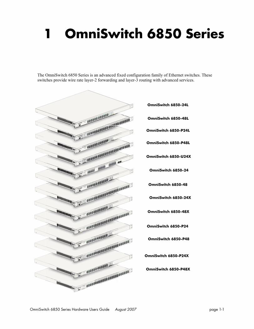
1 OmniSwitch 6850 Series
The OmniSwitch 6850 Series is an advanced fixed configuration family of Ethernet switches. These switches provide wire rate layer-2 forwarding and layer-3 routing with advanced services.
OmniSwitch 6850-24
OmniSwitch 6850-P24
OmniSwitch 6850-48
OmniSwitch 6850-24X
OmniSwitch 6850-P48
OmniSwitch 6850-48X
OmniSwitch 6850-P48X
OmniSwitch 6850-P24X
OmniSwitch 6850-24L
OmniSwitch 6850-U24X
OmniSwitch 6850-P24L
OmniSwitch 6850-P48L
Console
OmniSwitch 6850-24
OKPRI
PWRBPS
USB
CLASS 1 LASER PRODUCT
USB
USB
Console
OmniSwitch 6850-P24LOK
PRIPWR
BPS
1 2
3
4
5
6 7
8
9
1
0 11
12
13
14 15
16 17
18 19
20 21
22 23
24
CLASS 1 LASER PRODUCT
24
23
22
21
USB
Console
OmniSwitch 6850-24L
OKPRI
PWRBPS
1 2
3
4
5
6 7
8
9
1
0 11
12
13
14 15
16 17
18 19
20 21
22 23
24
CLASS 1 LASER PRODUCT
24
23
22
21
USB
Console
OmniSwitch 6850-48L
OKPRI
PWRBPS
CLASS 1 LASER PRODUCT
1
2
34
1
2
3 4
5
6
7 8
9 1
0 11
12
1
3 1
4 15
16
17
18
19 2
0 2
1 22
23
24
25
26 2
7 2
8 29
30
31
32 33
34
35
36
3
7 3
8 39
40
41
42 4
3 4
4 4
5 46
47
48
USB
Console
OmniSwitch 6850-P48LOK
PRIPWR
BPS
CLASS 1 LASER PRODUCT
1
2
34
1
2
3 4
5
6
7 8
9 1
0 11
12
13
14
15 1
6 1
7 1
8 19
20
21
22 2
3 2
4
2
5 26
27
28
29 3
0 3
1 32
33 3
4 3
5 36
37
38
39 4
0 4
1 42
43
44
45
46 4
7 4
8
1
2 3
4
5 6
7
8
9 1
0 11
12 1
3 14
15 1
6
17 18
19 2
0 2
1 22
23 2
4
23
24
1
3
5
7
9
11
13
15
17
1
9
2
1
2
5
10
12
1
4
1
6
18
20
2
2
2
4
2
4
6
8
USB
Console
OmniSwitch 6850-U24X
25
26
25
26
OKPRI
PWRBPS
CLASS 1 LASER PRODUCT
Console
OmniSwitch 6850-48
OKPRI
PWRBPS
CLASS 1 LASER PRODUCT
1
2
3
4
1
2
3 4
5
6
7 8
9 1
0 11
12
13
14
15 1
6 1
7 1
8 19
20
21
22 2
3 2
4
25
26 2
7 2
8 29
30
31
32 33
34
35
36
3
7 3
8 39
40
41
42 4
3 4
4 4
5 46
47
48
1 2
3
4
5
6 7
8
9
1
0 11
12
13
14 15
16 17
18 19
20 21
22 23
24
CLASS 1 LASER PRODUCT
24
23
22
21
USB
Console
OmniSwitch 6850-24X
25
26
25
26
OKPRI
PWRBPS
CLASS 1 LASER PRODUCT
USB
Console
OmniSwitch 6850-48X
OKPRI
PWRBPS
CLASS 1 LASER PRODUCT
50
50
49
49
1
2
3 4
5
6
7 8
9 1
0 11
12
13
14
15 1
6 1
7 1
8 19
20
21
22 2
3 2
4
2
5 26
27
28
29 3
0 3
1 32
33
34
35
36
3
7 3
8 39
40
41
42 43
44
45
46 4
7 4
8
Console
OmniSwitch 6850-P24
OKPRI
PWRBPS
1
2
3
4
5
6
7
8
9
10
11 12
13 14
15 16
17 18
19 20
21 22
23 24
CLASS 1 LASER PRODUCT
24
23
22
21
USB
Console
OmniSwitch 6850-P48
OKPRI
PWRBPS
CLASS 1 LASER PRODUCT
1
2
3
4
1
2
3 4
5
6
7 8
9 1
0 11
12
13
14
15 1
6 1
7 1
8 19
20
21
22 2
3 2
4
2
5 26
27
28
29
30
31
32 3
3 3
4 3
5 36
37
38
39 4
0 4
1 4
2 4
3 44
45
46
47
48
USB
1 2
3
4
5
6 7
8
9
1
0 11
12
13
14 15
16 17
18 19
20 21
22 23
24
CLASS 1 LASER PRODUCT
24
23
22
21
USB
Console
OmniSwitch 6850-P24X
25
26
25
26
OKPRI
PWRBPS
CLASS 1 LASER PRODUCT
Console
OmniSwitch 6850-P48X
OKPRI
PWRBPS
CLASS 1 LASER PRODUCT
50
50
49
49
1
2
3 4
5
6
7 8
9 1
0 11
12
13
14
15 1
6 1
7 1
8 19
20
21
22 2
3 2
4
2
5 26
27
28
29 3
0 3
1 32
33
34
35
36
3
7 3
8 39
40
41
42 4
3 4
4 4
5 46
47
48
USB
OmniSwitch 6850-48L
OmniSwitch 6850 Series Hardware Users Guide August 2007 page 1-1

OmniSwitch 6850 Series
• The OmniSwitch 6850-24L (OS6850-24L) is a 24-port, 10/100 fixed stackable chassis with four combo fiber SFP connectors.
• The OmniSwitch 6850-48L (OS6850-48L) is a 48-port, 10/100 fixed stackable chassis with four combo fiber SFP connectors.
• The OmniSwitch 6850-P24L (OS6850-P24L) is a 24-port, 10/100 PoE fixed stackable chassis with four combo fiber SFP connectors.
• The OmniSwitch 6850-P48L (OS6850-P48L) is a 48-port, 10/100 PoE fixed stackable chassis with four combo fiber SFP connectors.
• The OmniSwitch 6850-U24X (OS6850-U24X) is a 24-port, 1000Base-X SFP fixed stackable chassis with two 10/100/1000 Base-T combo ports. This switch also includes two 10-Gigabit XFP connectors.
• The OmniSwitch 6850-24 (OS6850-24) is a 24-port, 10/100/1000 fixed stackable chassis with four combo fiber SFP connectors.
• The OmniSwitch 6850-48 (OS6850-48) is a 48-port, 10/100/1000 fixed stackable chassis with four combo fiber SFP connectors.
• The OmniSwitch 6850-24X (OS6850-24X) is a 24-port, 10/100/1000 fixed stackable chassis with four combo fiber SFP connectors.This switch also includes two 10-Gigabit XFP connectors.
• The OmniSwitch 6850-48X (OS6850-48X) is a 48-port, 10/100/1000 fixed stackable chassis. This switch also includes two 10-Gigabit XFP connectors.
• The OmniSwitch 6850-P24 (OS6850-P24) is a 24-port, 10/100/1000 PoE fixed stackable chassis with four combo fiber SFP connectors.
• The OmniSwitch 6850-P48 (OS6850-P48) is a 48-port, 10/100/1000 PoE fixed stackable chassis with four combo fiber SFP connectors.
• The OmniSwitch 6850-P24X (OS6850-P24X) is a 24-port, 10/100/1000 PoE fixed stackable chassis with four combo fiber SFP connectors. This switch also includes two 10-Gigabit XFP connectors.
• The OmniSwitch 6850-P48X (OS6850-P48X) is a 48-port, 10/100/1000 PoE fixed stackable chassis. This switch also includes two 10-Gigabit XFP connectors.
The OmniSwitch 6850 Series switches offer effective availability, resiliency, and security features and are ideal for the following network applications:
• Enterprise workgroups/LAN wiring closets
• Edge deployments and branch offices
• L3 aggregation/distribution layer switches in three-tier networks
• Small enterprise core switching
• Quality of service (QoS) for mission critical applications
• Data center server clusters
page 1-2 OmniSwitch 6850 Series Hardware Users Guide August 2007
OmniSwitch 6850 Series Availability Features
Availability FeaturesThe switch provides a broad variety of availability features. Availability features are hardware and software-based safeguards that help to prevent the loss of data flow in the unlikely event of a subsystem failure. In addition, some availability features allow users to maintain or replace hardware components without powering off the switch or interrupting switch operations. Combined, these features provide added resiliency and help to ensure that the switch or virtual chassis is consistently available for day-to-day network operations.
Hardware-related availability features include:
• Software Rollback
• Backup Power Supplies
• Hot Swapping
• Hardware Monitoring
Software RollbackSoftware rollback (also referred to as image rollback) essentially allows the OmniSwitch 6850 Series switches to return to a prior “last known good” version of software in the event of a system software prob-lem. The switch controls software rollback through its resilient directory structure design (i.e., /flash/working and /flash/certified).
For detailed information on the software rollback feature, as well as the switch’s /flash/working and /flash/certified directories, refer to the “Managing CMM Directory Content” chapter in the OmniSwitch 6800/6850/9000 Series Switch Management Guide.
Backup Power SuppliesThe OmniSwitch 6850 Series switches support an optional backup power supply. This power supply is connected to the rear of the unit. There is a power shelf provided with the unit that slides into the rear of the chassis and is used to hold the power supplies. It can hold 510W or 360W power supply or in case of non-PoE product switches 120W or 126W power supply. This provides redundant chassis power on a 1:1 basis.
Backup power supplies operate in active standby mode. If the primary power supply fails unexpectedly, the backup power supply automatically takes up the full power load without disrupting the switch.
Note. For more information on backup power supplies, refer to Chapter 2, “OmniSwitch 6850 Series Chassis and Hardware Components.”
OmniSwitch 6850 Series Hardware Users Guide August 2007 page 1-3
Availability Features OmniSwitch 6850 Series
Hot SwappingHot swapping refers to the action of adding, removing, or replacing components without powering off switches or disrupting other components.This feature facilitates hardware upgrades and maintenance and allows users to easily replace components in the unlikely event of hardware failure.
The following hardware components can be hot swapped:
• Backup power supply
• Backup power supply connector cables
• SFPs
For instructions on hot swapping backup power supplies, refer to Chapter 2, “OmniSwitch 6850 Series Chassis and Hardware Components.” For instructions on hot swapping combo connector SFPs, refer to the instruction card provided with the SFP product.
Hardware Monitoring
Automatic Monitoring
Automatic monitoring refers to the switch’s built-in sensors that automatically monitor operations. If an error is detected (e.g., over-threshold temperature), the switch immediately sends a trap to the user. The trap is displayed on the console in the form of a text error message. (In the case of an over-threshold temperature condition, the chassis displays an amber TMP LED in addition to sending a trap.)
LEDs
LEDs, which provide visual status information, are provided on the chassis front panel. LEDs are used to indicate conditions such as hardware and software status, temperature errors, link integrity, data flow, etc. For detailed LED descriptions, refer to Chapter 2, “OmniSwitch 6850 Series Chassis and Hardware Components.”
User-Driven Monitoring
User-driven hardware monitoring refers to CLI commands that are entered by the user in order to access the current status of hardware components. The user enters “show” commands that output information to the console. Monitoring information for chassis components, such as the optional back up power supply, chassis temperature sensor, and chassis fans is provided in Chapter 2, “OmniSwitch 6850 Series Chassis and Hardware Components.” The show commands for all the features are described in detail in the OmniSwitch CLI Reference Guide.
page 1-4 OmniSwitch 6850 Series Hardware Users Guide August 2007
OmniSwitch 6850 Series OmniSwitch 6850 Series Application Examples
OmniSwitch 6850 Series Application ExamplesThe following OmniSwitch 6850 Series applications are described below:
• Gigabit-to-the-desktop migration
• Server aggregation
• Layer 3 Aggregation/Distribution
• Small Enterprise core
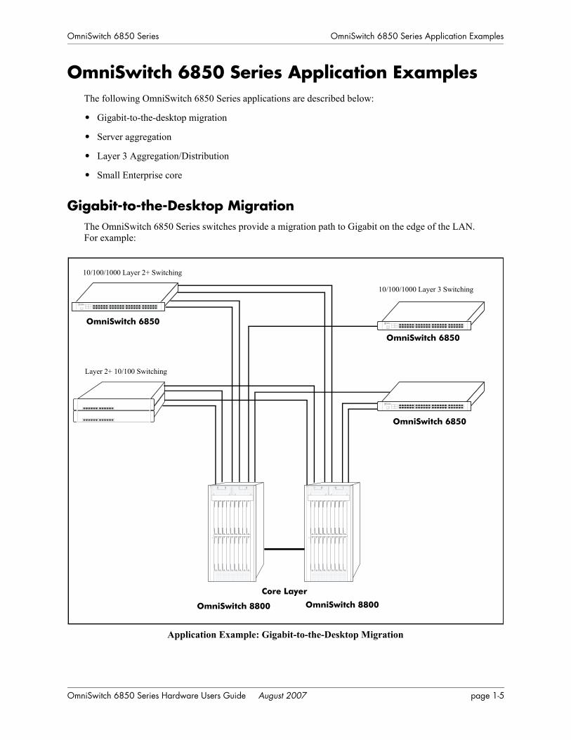
Gigabit-to-the-Desktop MigrationThe OmniSwitch 6850 Series switches provide a migration path to Gigabit on the edge of the LAN. For example:
Application Example: Gigabit-to-the-Desktop Migration
Layer 2+ 10/100 Switching
Core Layer
10/100/1000 Layer 2+ Switching
10/100/1000 Layer 3 Switching
OmniSwitch 6850
OmniSwitch 6850
OmniSwitch 6850
OmniSwitch 8800 OmniSwitch 8800
OmniSwitch 6850 Series Hardware Users Guide August 2007 page 1-5
OmniSwitch 6850 Series Application Examples OmniSwitch 6850 Series
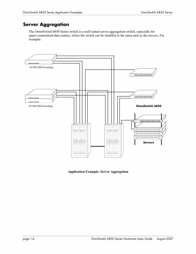
Server AggregationThe OmniSwitch 6850 Series switch is a well-suited server aggregation switch, especially for space-constrained data centers, where the switch can be installed in the same rack as the servers. For example:
Application Example: Server Aggregation
10/100/1000 Switching
10/100/1000 Switching
Servers
OmniSwitch 6850
page 1-6 OmniSwitch 6850 Series Hardware Users Guide August 2007
OmniSwitch 6850 Series OmniSwitch 6850 Series Application Examples
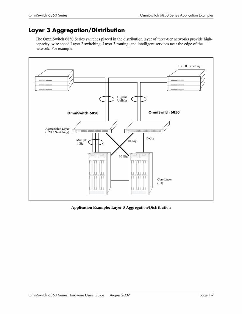
Layer 3 Aggregation/DistributionThe OmniSwitch 6850 Series switches placed in the distribution layer of three-tier networks provide high-capacity, wire speed Layer 2 switching, Layer 3 routing, and intelligent services near the edge of the network. For example:
Application Example: Layer 3 Aggregation/Distribution
10/100 Switching
Aggregation Layer
Gigabit
Multiple 10 Gig10 Gig
10 Gig
1 Gig
Uplinks
(L2/L3 Switching)
Core Layer(L3)
OmniSwitch 6850OmniSwitch 6850
OmniSwitch 6850 Series Hardware Users Guide August 2007 page 1-7
OmniSwitch 6850 Series Application Examples OmniSwitch 6850 Series
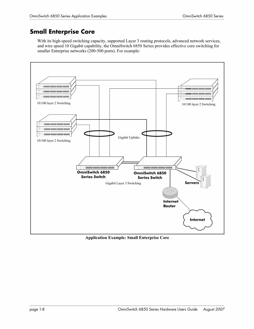
Small Enterprise CoreWith its high-speed switching capacity, supported Layer 3 routing protocols, advanced network services, and wire speed 10 Gigabit capability, the OmniSwitch 6850 Series provides effective core switching for smaller Enterprise networks (200-500 ports). For example:
Application Example: Small Enterprise Core
10/100 layer 2 Switching
ServersGigabit Layer 3 Switching
Internet
Internet
Router
Gigabit Uplinks
10/100 layer 2 Switching
10/100 layer 2 Switching
OmniSwitch 6850 Series Switch
OmniSwitch 6850 Series Switch
page 1-8 OmniSwitch 6850 Series Hardware Users Guide August 2007

2 OmniSwitch 6850 SeriesChassis and Hardware
Components
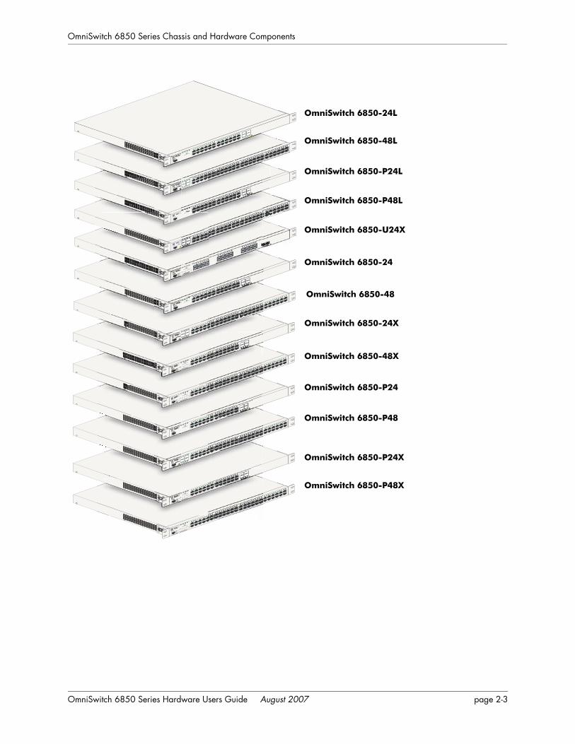
OmniSwitch 6850 Series switches are available in thirteen stackable chassis configurations as shown in the table below:
• OmniSwitch 6850-24L (OS6850-24L)
24-port 10/100
• OmniSwitch 6850-48L (OS6850-48L)
48-port 10/100
• OmniSwitch 6850-P24L (OS6850-P24L)
24-port 10/100 Power over Ethernet (PoE)
• OmniSwitch 6850-P48L (OS6850-P48L)
48-port 10/100 Power over Ethernet (PoE)
• OmniSwitch 6850-U24X (OS6850-U24X)
24-port Gigabit SFP with 10 Gigabit uplinks
• OmniSwitch 6850-24(OS6850-24)
24-port 10/100/1000
• OmniSwitch 6850-48 (OS6850-48)
48-port 10/100/1000
• OmniSwitch 6850-24X (OS6850-24X)
24-port with 10 Gigabit uplinks
• OmniSwitch 6850-48X (OS6850-48X)
48-port with 10 Gigabit uplinks
• OmniSwitch 6850-P24 (OS6850-P24)
24-port 10/100/1000 Power over Ethernet (PoE)
• OmniSwitch 6850-P48 (OS6850-P48)
48-port 10/100/1000 Power over Ethernet (PoE)
• OmniSwitch 6850-P24X (OS6850-P24X)
24-port PoE with 10 Gigabit uplinks
• OmniSwitch 6850-P48X (OS6850-P48X)
48-port PoE with 10 Gigabit uplinks
OmniSwitch 6850 Series Hardware Users Guide August 2007 page 2-1

OmniSwitch 6850 Series Chassis and Hardware Components
This chapter includes detailed information on these chassis types. Topics include:
• OmniSwitch 6850 Series chassis descriptions
• Technical specifications
• Switch mounting
• Booting OmniSwitch 6850 Series switches
• Power cords, console port, and pinout specifications
• OmniSwitch 6850 Series power supplies
• Monitoring the chassis
page 2-2 OmniSwitch 6850 Series Hardware Users Guide August 2007
OmniSwitch 6850 Series Chassis and Hardware Components
OmniSwitch 6850-48
OmniSwitch 6850-P48X
OmniSwitch 6850-P48
OmniSwitch 6850-24X
OmniSwitch 6850-P24
OmniSwitch 6850-48X
OmniSwitch 6850-P24X
OmniSwitch 6850-24
OmniSwitch 6850-48L
OmniSwitch 6850-24L
OmniSwitch 6850-U24X
OmniSwitch 6850-P24L
OmniSwitch 6850-P48L
Console
OmniSwitch 6850-24
OKPRI
PWRBPS
USB
CLASS 1 LASER PRODUCT
USB
USB
Console
OmniSwitch 6850-P24LOK
PRIPWR
BPS
1 2
3
4
5
6 7
8
9
1
0 11
12
13
14 15
16 17
18 19
20 21
22 23
24
CLASS 1 LASER PRODUCT
24
23
22
21
USB
Console
OmniSwitch 6850-24L
OKPRI
PWRBPS
1 2
3
4
5
6 7
8
9
1
0 11
12
13
14 15
16 17
18 19
20 21
22 23
24
CLASS 1 LASER PRODUCT
24
23
22
21
USB
Console
OmniSwitch 6850-48L
OKPRI
PWRBPS
CLASS 1 LASER PRODUCT
1
2
34
1
2
3 4
5
6
7 8
9 1
0 11
12
13
14
15 1
6 1
7 1
8 19
20
21
22 2
3 2
4
2
5 26
27
28
29 3
0 3
1 32
33
34
35
36
3
7 3
8 39
40
41
42 4
3 4
4 4
5 46
47
48
USB
Console
OmniSwitch 6850-P48LOK
PRIPWR
BPS
CLASS 1 LASER PRODUCT
1
2
34
1
2
3 4
5
6
7 8
9 1
0 11
12
13
14
15 1
6 1
7 1
8 19
20
21
22 2
3 2
4
2
5 26
27
28
29 3
0 3
1 32
33
34
35
36
3
7 3
8 39
40
41
42 4
3 4
4 4
5 46
47
48
1
2 3
4
5 6
7
8
9 1
0 11
12 1
3 14
15 1
6
17 18
19 2
0 2
1 22
23 2
4
23
24
1
3
5
7
9
11
1
3
1
5
17
1
9
2
1
2
5
10
12
1
4
1
6
18
20
2
2
2
4
2
4
6
8
USB
Console
OmniSwitch 6850-U24X
25
26
25
26
OKPRI
PWRBPS
CLASS 1 LASER PRODUCT
Console
OmniSwitch 6850-48
OKPRI
PWRBPS
CLASS 1 LASER PRODUCT
1
2
3
4
1
2
3 4
5
6
7 8
9 1
0 11
12
13
14
15 1
6 1
7 1
8 19
20
21
22 2
3 2
4
2
5 26
27
28
29 3
0 3
1 32
33
34
35
36
3
7 3
8 39
40
41
42 4
3 4
4 4
5 46
47
48
1 2
3
4
5
6 7
8
9
1
0 11
12
13
14 15
16 17
18 19
20 21
22 23
24
CLASS 1 LASER PRODUCT
24
23
22
21
USB
Console
OmniSwitch 6850-24X
25
26
25
26
OKPRI
PWRBPS
CLASS 1 LASER PRODUCT
USB
Console
OmniSwitch 6850-48X
OKPRI
PWRBPS
CLASS 1 LASER PRODUCT
50
50
49
49
1
2
3 4
5
6
7 8
9 1
0 11
12
13
14
15 1
6 1
7 1
8 19
20
21
22 2
3 2
4
2
5 26
27
28
29 3
0 3
1 32
33
34
35
36
3
7 3
8 39
40
41
42 4
3 4
4 4
5 46
47
48
Console
OmniSwitch 6850-P24
OKPRI
PWRBPS
1
2
3
4
5
6
7
8
9
10
11 12
13 14
15 16
17 18
19 20
21 22
23 24
CLASS 1 LASER PRODUCT
24
23
22
21
USB
Console
OmniSwitch 6850-P48
OKPRI
PWRBPS
CLASS 1 LASER PRODUCT
1
2
3
4
1
2
3 4
5
6
7 8
9 1
0 11
12
13
14
15 1
6 1
7 1
8 19
20
21
22 2
3 2
4
2
5 26
27
28
29
30
31
32 3
3 3
4 3
5 36
37
38
39 4
0 4
1 4
2 4
3 44
45
46
47
48
USB
1 2
3
4
5
6 7
8
9
1
0 11
12
13
14 15
16 17
18 19
20 21
22 23
24
CLASS 1 LASER PRODUCT
24
23
22
21
USB
Console
OmniSwitch 6850-P24X
25
26
25
26
OKPRI
PWRBPS
CLASS 1 LASER PRODUCT
Console
OmniSwitch 6850-P48X
OKPRI
PWRBPS
CLASS 1 LASER PRODUCT
50
50
49
49
1
2
3 4
5
6
7 8
9 1
0 11
12
13
14
15 1
6 1
7 1
8 19
20
21
22 2
3 2
4
2
5 26
27
28
29 3
0 3
1 32
33
34
35
36
3
7 3
8 39
40
41
42 4
3 4
4 4
5 46
47
48
USB
OmniSwitch 6850 Series Hardware Users Guide August 2007 page 2-3

OmniSwitch 6850-24L OmniSwitch 6850 Series Chassis and Hardware Components
OmniSwitch 6850-24LThe OmniSwitch 6850-24L is a stackable edge/workgroup switch offering 20 unshared 10/100Base-T, as well as four combo individually configurable to be 10/100/1000Base-T or 1000Base-Xhigh-speed connections.
The front panel of the OS6850-24L chassis contains the following major components:
• System status and slot indicator LEDs
• (20) unshared 10/100Base-T
• (4) shared combo 10/100/1000Base-T
• (4) Combo SFP connectors for 1000Base-X connections
• Console port (RJ-45)
• USB port (USB 2.0)
Note. USB 2.0 is not supported in this release.
Note. The 20 (non-combo) 10/100Base-T on the OmniSwitch 6850-24L can be upgraded to 10/100/1000Base-T. Please contact your Alcatel-Lucent representative for more information.
page 2-4 OmniSwitch 6850 Series Hardware Users Guide August 2007
OmniSwitch 6850 Series Chassis and Hardware Components OmniSwitch 6850-24L
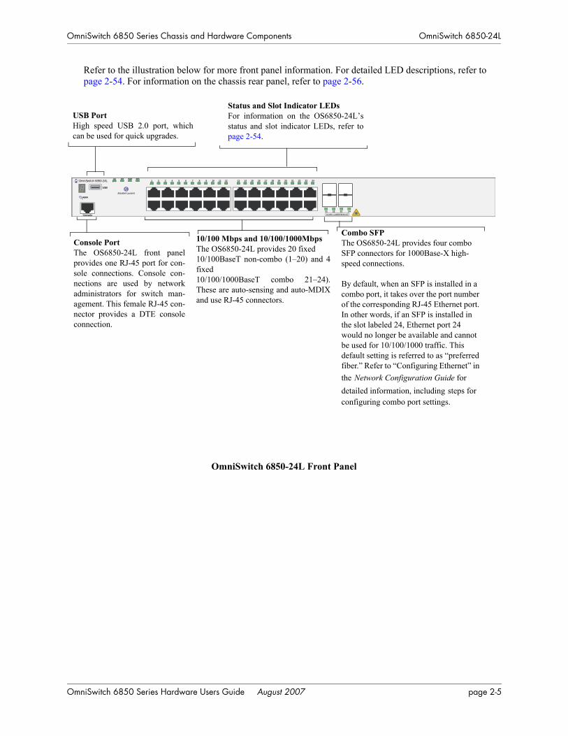
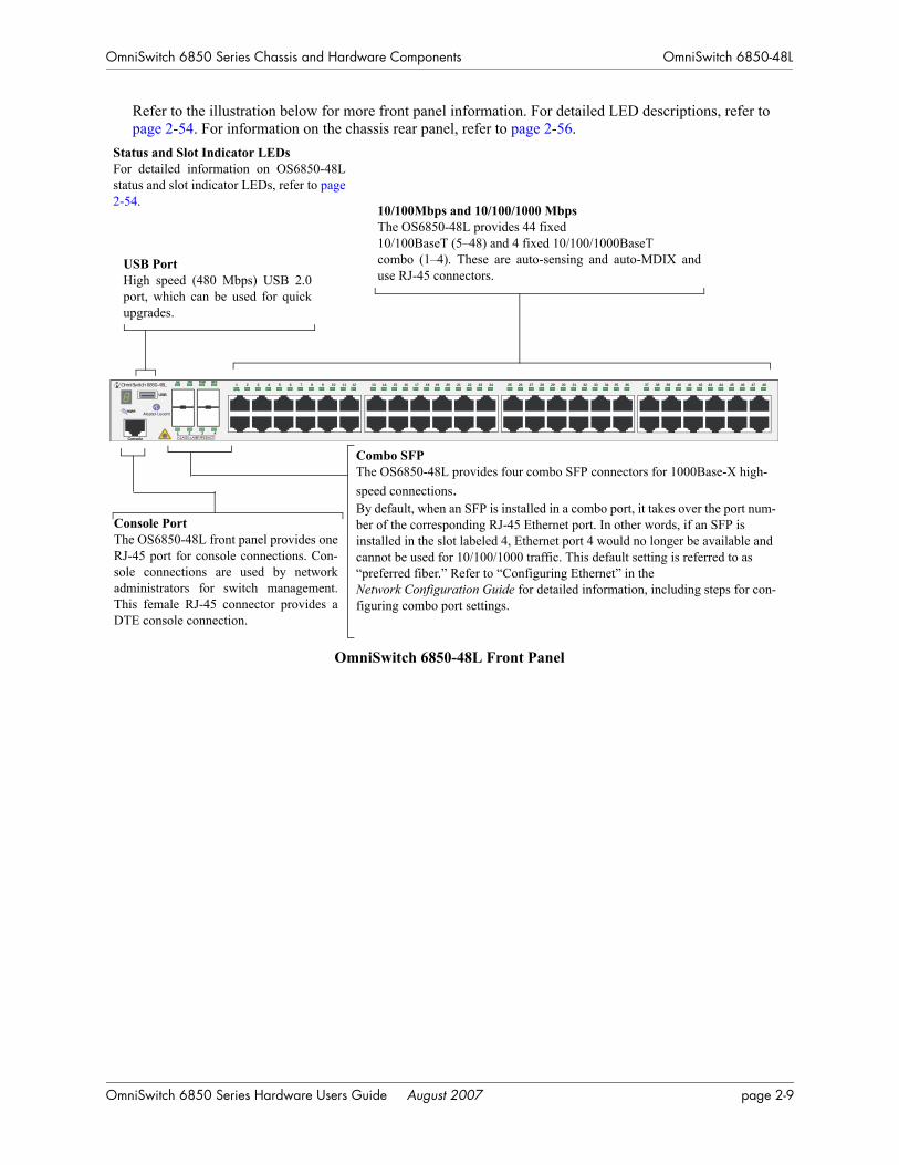
Refer to the illustration below for more front panel information. For detailed LED descriptions, refer to page 2-54. For information on the chassis rear panel, refer to page 2-56.
OmniSwitch 6850-24L Front Panel
10/100 Mbps and 10/100/1000Mbps The OS6850-24L provides 20 fixed 10/100BaseT non-combo (1–20) and 4fixed 10/100/1000BaseT combo 21–24).These are auto-sensing and auto-MDIXand use RJ-45 connectors.
Console PortThe OS6850-24L front panelprovides one RJ-45 port for con-sole connections. Console con-nections are used by networkadministrators for switch man-agement. This female RJ-45 con-nector provides a DTE consoleconnection.
Status and Slot Indicator LEDsFor information on the OS6850-24L’sstatus and slot indicator LEDs, refer topage 2-54.
USB PortHigh speed USB 2.0 port, whichcan be used for quick upgrades.
Combo SFP The OS6850-24L provides four combo SFP connectors for 1000Base-X high-speed connections.
By default, when an SFP is installed in a combo port, it takes over the port number of the corresponding RJ-45 Ethernet port. In other words, if an SFP is installed in the slot labeled 24, Ethernet port 24 would no longer be available and cannot be used for 10/100/1000 traffic. This default setting is referred to as “preferred fiber.” Refer to “Configuring Ethernet” in the Network Configuration Guide for detailed information, including steps for configuring combo port settings.
OmniSwitch 6850-24L
USB
OK PRI PWR BPS
Console CLASS 1 LASER PRODUCT
1 2 3 4 5 6 7 8 9 10 11 12 13 14 15 16 17 18 19 20 21 22 23 24
21 22 23 24
OmniSwitch 6850 Series Hardware Users Guide August 2007 page 2-5

OmniSwitch 6850-24L OmniSwitch 6850 Series Chassis and Hardware Components
OS6850-24L Specifications
Total unshared 10/100Base-T per switch (1–20)
20
Total shared 10/100/1000Base-T combo per switch(21–24)
4
Total combo 1000Base-X combo SFP connectors per switch (21–24)
4
Total 10/100Base-T per stack 160 (stack of eight switches)
Total combo SFP connectors per stack
32 (stack of eight switches)
Power 126/120W (AC/DC) power supply
Flash memory size 64 MB
RAM memory size 256 MB SDRAM
Overall Width (rack-mount flanges included)
19 inches, approx.
Chassis Width (rack-mount flanges not included)
17.5 inches
Height 1.73 inches
Height (rack units) 1 RU
Chassis Depth 10.5 inches without power supplies installed;16.75 inches with power supplies installed
Weight 14 lbs (6.24 Kg), approx.
Humidity 5% to 90% Relative Humidity (Operating)0% to 95% Relative Humidity (Storage)
Operating Temperature 0 to 45 degrees, Celsius
Storage Temperature -20 to 70 degrees, Celsius
Altitude Operating altitude: sea level at 40 degrees, Celsius and 10000 feet at 0 degrees, CelsiusStorage altitude: sea level to 40000 feet
Standards supported 802.3z, 802.3ab, 1000Base-T, IEEE 802.3u
Data rate (RJ-45) 10 or 100 Mbps (full or half duplex)1 Gigabit per second (full duplex)
Data rate (SFP) 1 Gigabit per second (full duplex)
Maximum frame size 9216 bytes
Connections supported 10/100/1000Base-T and 1000Base-X
Cable supported(RJ-45)
10BaseT: unshielded twisted-pair (UTP)100BaseTX: unshielded twisted-pair (UTP), Category 5, EIA/TIA 568 or shielded twisted-pair (STP), Category 5, 100 ohm1000BaseT: unshielded twisted-pair (UTP), Category 5e
page 2-6 OmniSwitch 6850 Series Hardware Users Guide August 2007

OmniSwitch 6850 Series Chassis and Hardware Components OmniSwitch 6850-24L
Maximum cable distance(RJ-45)
100 meters
OS6850-24L Specifications
OmniSwitch 6850 Series Hardware Users Guide August 2007 page 2-7

OmniSwitch 6850-48L OmniSwitch 6850 Series Chassis and Hardware Components
OmniSwitch 6850-48LThe OmniSwitch 6850-48L is a stackable edge/workgroup switch offering 44 unshared 10/100Base-T, as well as four combo individually configurable to 10/100/1000Base-T or 1000Base-X high speed connec-tions.
The front panel of the OS6850-48L chassis contains the following major components:
• System status and slot indicator LEDs
• (44) unshared 10/100Base-T
• (4) shared combo 10/100/1000Base-T
• (4) Combo SFP connectors for 1000Base-X connections
• Console port (RJ-45)
• USB port (USB 2.0)
Note. USB 2.0 is not supported in this release.
Note. The 44 (non-combo) 10/100Base-T on the OmniSwitch 6850-48L can be upgraded to 10/100/1000Base-T. Please contact your Alcatel-Lucent representative for more information.
page 2-8 OmniSwitch 6850 Series Hardware Users Guide August 2007
OmniSwitch 6850 Series Chassis and Hardware Components OmniSwitch 6850-48L
Refer to the illustration below for more front panel information. For detailed LED descriptions, refer to page 2-54. For information on the chassis rear panel, refer to page 2-56.
OmniSwitch 6850-48L Front Panel
10/100Mbps and 10/100/1000 Mbps The OS6850-48L provides 44 fixed 10/100BaseT (5–48) and 4 fixed 10/100/1000BaseT combo (1–4). These are auto-sensing and auto-MDIX anduse RJ-45 connectors.
Console PortThe OS6850-48L front panel provides oneRJ-45 port for console connections. Con-sole connections are used by networkadministrators for switch management.This female RJ-45 connector provides aDTE console connection.
Status and Slot Indicator LEDsFor detailed information on OS6850-48Lstatus and slot indicator LEDs, refer to page2-54.
USB PortHigh speed (480 Mbps) USB 2.0port, which can be used for quickupgrades.
Combo SFP The OS6850-48L provides four combo SFP connectors for 1000Base-X high-speed connections.By default, when an SFP is installed in a combo port, it takes over the port num-ber of the corresponding RJ-45 Ethernet port. In other words, if an SFP is installed in the slot labeled 4, Ethernet port 4 would no longer be available and cannot be used for 10/100/1000 traffic. This default setting is referred to as “preferred fiber.” Refer to “Configuring Ethernet” in the Network Configuration Guide for detailed information, including steps for con-figuring combo port settings.
OmniSwitch 6850-48L
USB
Console
OK PRI PWR BPS
CLASS 1 LASER PRODUCT1 2 3 4
1 2 3 4 5 6 7 8 9 10 11 12 13 14 15 16 17 18 19 20 21 22 23 24 25 26 27 28 29 30 31 32 33 34 35 36 37 38 39 40 41 42 43 44 45 46 47 48
OmniSwitch 6850 Series Hardware Users Guide August 2007 page 2-9

OmniSwitch 6850-48L OmniSwitch 6850 Series Chassis and Hardware Components
OS6850-48L Specifications
Total unshared 10/100Base-T per switch (5–48)
44
Total shared 10/100/1000Base-T combo per switch (1–4)
4
Total combo SFP connectors per switch
4
Total 10/100Base-T per stack 352 (stack of eight switches)
Total combo SFP connectors per stack
32 (stack of eight switches)
Power 126/120W (AC/DC) power supply
Flash memory size 64 MB
RAM memory size 256 MB SDRAM
Overall Width (rack-mount flanges included)
19 inches, approx.
Chassis Width (rack-mount flanges not included)
17.5 inches
Height 1.73 inches
Height (rack units) 1 RU
Chassis Depth 10.5 inches without power supplies installed;16.75 inches with power supplies installed
Weight 14 lbs (6.24 Kg), approx.
Humidity 5% to 90% Relative Humidity (Operating)0% to 95% Relative Humidity (Storage)
Operating Temperature 0 to 45 degrees, Celsius
Storage Temperature -20 to 70 degrees, Celsius
Altitude Operating altitude: sea level at 40 degrees, Celsius and 10000 feet at 0 degrees, CelsiusStorage altitude: sea level to 40000 feet
Standards supported 802.3z, 802.3ab, 1000Base-T, IEEE 802.3u
Data rate (RJ-45) 10 or 100 Mbps (full or half duplex)1 Gigabit per second (full duplex)
Data rate (SFP) 1 Gigabit per second (full duplex)
Maximum frame size 9216
Connections supported 10/100/1000Base-T and 1000Base-X
Cable supported(RJ-45)
10BaseT: unshielded twisted-pair (UTP)100BaseTX: unshielded twisted-pair (UTP), Category 5, EIA/TIA 568 or shielded twisted-pair (STP), Category 5, 100 ohm1000BaseT: unshielded twisted-pair (UTP), Category 5e
Maximum cable distance(RJ-45)
100 meters
page 2-10 OmniSwitch 6850 Series Hardware Users Guide August 2007

OmniSwitch 6850 Series Chassis and Hardware Components OmniSwitch 6850-P24L
OmniSwitch 6850-P24LThe OmniSwitch 6850-P24L is a stackable edge/workgroup switch offering 20 unshared 10/100Base-T Power over Ethernet (PoE), as well as four combo individually configurable to be10/100/1000Base-T PoE or 1000Base-X high speed connections.
The front panel of the OS6850-P24L chassis contains the following major components:
• System status and slot indicator LEDs
• (20) unshared 10/100Base-T PoE
• (4) shared combo 10/100/1000Base-T PoE
• (4) Combo SFP connectors for 1000Base-X connections
• Console port (RJ-45)
• USB port (USB 2.0)
Note. USB 2.0 is not supported in this release.
Note. The 20 (non-combo) 10/100Base-T PoE on the OmniSwitch 6850-P24L can be upgraded to 10/100/1000Base-T PoE. Please contact your Alcatel-Lucent representative for more information.
OmniSwitch 6850 Series Hardware Users Guide August 2007 page 2-11
OmniSwitch 6850-P24L OmniSwitch 6850 Series Chassis and Hardware Components
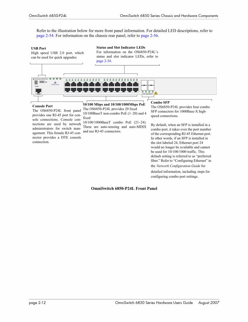
Refer to the illustration below for more front panel information. For detailed LED descriptions, refer to page 2-54. For information on the chassis rear panel, refer to page 2-56.
OmniSwitch 6850-P24L Front Panel
10/100 Mbps and 10/100/1000Mbps PoE The OS6850-P24L provides 20 fixed 10/100BaseT non-combo PoE (1–20) and 4fixed 10/100/1000BaseT combo PoE (21–24).These are auto-sensing and auto-MDIXand use RJ-45 connectors.
Console PortThe OS6850-P24L front panelprovides one RJ-45 port for con-sole connections. Console con-nections are used by networkadministrators for switch man-agement. This female RJ-45 con-nector provides a DTE consoleconnection.
Status and Slot Indicator LEDsFor information on the OS6850-P24L’sstatus and slot indicator LEDs, refer topage 2-54.
USB PortHigh speed USB 2.0 port, whichcan be used for quick upgrades.
Combo SFP The OS6850-P24L provides four combo SFP connectors for 1000Base-X high-speed connections.
By default, when an SFP is installed in a combo port, it takes over the port number of the corresponding RJ-45 Ethernet port. In other words, if an SFP is installed in the slot labeled 24, Ethernet port 24 would no longer be available and cannot be used for 10/100/1000 traffic. This default setting is referred to as “preferred fiber.” Refer to “Configuring Ethernet” in the Network Configuration Guide for detailed information, including steps for configuring combo port settings.
OmniSwitch 6850-P24L
USB
OK PRI PWR BPS
Console CLASS 1 LASER PRODUCT
1 2 3 4 5 6 7 8 9 10 11 12 13 14 15 16 17 18 19 20 21 22 23 24
21 22 23 24
page 2-12 OmniSwitch 6850 Series Hardware Users Guide August 2007

OmniSwitch 6850 Series Chassis and Hardware Components OmniSwitch 6850-P24L
OS6850-P24L Specifications
Total unshared 10/100Base-T PoE per switch (1–20)
20
Total shared 10/100/1000Base-T combo PoE per switch (21–24)
4
Total combo 1000Base-X combo SFP connectors per switch (21–24)
4
Total 10/100Base-T PoE per stack
160 (stack of eight switches)
Total combo SFP connectors per stack
32 (stack of eight switches)
Power 510/360W power supply
Flash memory size 64 MB
RAM memory size 256 MB SDRAM
Overall Width (rack-mount flanges included)
19 inches, approx.
Chassis Width (rack-mount flanges not included)
17.5 inches
Height 1.73 inches
Height (rack units) 1 RU
Chassis Depth 10.5 inches without power supplies installed;16.75 inches with power supplies installed
Weight 14 lbs (6.24 Kg), approx.
Humidity 5% to 90% Relative Humidity (Operating)0% to 95% Relative Humidity (Storage)
Operating Temperature 0 to 45 degrees, Celsius
Storage Temperature -20 to 70 degrees, Celsius
Altitude Operating altitude: sea level at 40 degrees, Celsius and 10000 feet at 0 degrees, CelsiusStorage altitude: sea level to 40000 feet
Standards supported 802.3z, 802.3ab, 1000Base-T, IEEE 802.3u, 802.3af (DTE Power via MDI MIB); IAB RFCs 826, 894
Data rate (RJ-45) 10 or 100 Mbps (full or half duplex)1 Gigabit per second (full duplex)
Data rate (SFP) 1 Gigabit per second (full duplex)
Maximum frame size 9216 bytes
Connections supported IP phones, Bluetooth Access Points, Internet cameras, and other devices requiring power over Ethernet
OmniSwitch 6850 Series Hardware Users Guide August 2007 page 2-13

OmniSwitch 6850-P24L OmniSwitch 6850 Series Chassis and Hardware Components
Cable supported(RJ-45)
10BaseT: unshielded twisted-pair (UTP)100BaseTX: unshielded twisted-pair (UTP), Category 5, EIA/TIA 568 or shielded twisted-pair (STP), Category 5, 100 ohm1000BaseT: unshielded twisted-pair (UTP), Category 5e
Power supplied to port 15.4 watts per port
Maximum cable distance(RJ-45)
100 meters
OS6850-P24L Specifications
page 2-14 OmniSwitch 6850 Series Hardware Users Guide August 2007

OmniSwitch 6850 Series Chassis and Hardware Components OmniSwitch 6850-P48L
OmniSwitch 6850-P48LThe OmniSwitch 6850-P48L is a stackable edge/workgroup switch offering 44 unshared 10/100Base-T Power over Ethernet (PoE), as well as four combo individually configurable to 10/100/1000Base-T PoE or 1000Base-X high speed connections.
The front panel of the OS6850-P48L chassis contains the following major components:
• System status and slot indicator LEDs
• (44) unshared 10/100Base-T PoE
• (4) shared combo 10/100/1000Base-T PoE
• (4) Combo SFP connectors for 1000Base-X connections
• Console port (RJ-45)
• USB port (USB 2.0)
Note. USB 2.0 is not supported in this release.
Note. The 44 (non-combo) 10/100Base-T PoE on the OmniSwitch 6850-P48L can be upgraded to 10/100/1000Base-T PoE. Please contact your Alcatel-Lucent representative for more information.
OmniSwitch 6850 Series Hardware Users Guide August 2007 page 2-15
OmniSwitch 6850-P48L OmniSwitch 6850 Series Chassis and Hardware Components
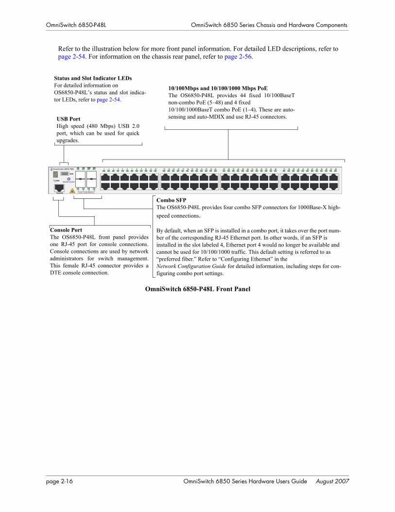
Refer to the illustration below for more front panel information. For detailed LED descriptions, refer to page 2-54. For information on the chassis rear panel, refer to page 2-56.
OmniSwitch 6850-P48L Front Panel
10/100Mbps and 10/100/1000 Mbps PoE The OS6850-P48L provides 44 fixed 10/100BaseTnon-combo PoE (5–48) and 4 fixed 10/100/1000BaseT combo PoE (1–4). These are auto-sensing and auto-MDIX and use RJ-45 connectors.
Console PortThe OS6850-P48L front panel providesone RJ-45 port for console connections.Console connections are used by networkadministrators for switch management.This female RJ-45 connector provides aDTE console connection.
Status and Slot Indicator LEDsFor detailed information on OS6850-P48L’s status and slot indica-tor LEDs, refer to page 2-54.
USB PortHigh speed (480 Mbps) USB 2.0port, which can be used for quickupgrades.
Combo SFP The OS6850-P48L provides four combo SFP connectors for 1000Base-X high-speed connections.
By default, when an SFP is installed in a combo port, it takes over the port num-ber of the corresponding RJ-45 Ethernet port. In other words, if an SFP is installed in the slot labeled 4, Ethernet port 4 would no longer be available and cannot be used for 10/100/1000 traffic. This default setting is referred to as “preferred fiber.” Refer to “Configuring Ethernet” in the Network Configuration Guide for detailed information, including steps for con-figuring combo port settings.
OmniSwitch 6850-P48L
USB
OK PRI PWR BPS
Console CLASS 1 LASER PRODUCT1 2 3 4
1 2 3 4 5 6 7 8 9 10 11 12 13 14 15 16 17 18 19 20 21 22 23 24 25 26 27 28 29 30 31 32 33 34 35 36 37 38 39 40 41 42 43 44 45 46 47 48
page 2-16 OmniSwitch 6850 Series Hardware Users Guide August 2007

OmniSwitch 6850 Series Chassis and Hardware Components OmniSwitch 6850-P48L
OS6850-P48L Specifications
Total unshared 10/100Base-T PoE per switch (5–48)
44
Total shared 10/100/1000Base-T combo PoE per switch (1–4)
4
Total combo 1000Base-X combo SFP connectors per switch
4
Total 10/100Base-T PoE per stack
352 (stack of eight switches)
Total combo SFP connectors per stack
32 (stack of eight switches)
Power 510/360W power supply
Flash memory size 64 MB
RAM memory size 256 MB SDRAM
Overall Width (rack-mount flanges included)
19 inches, approx.
Chassis Width (rack-mount flanges not included)
17.5 inches
Height 1.73 inches
Height (rack units) 1 RU
Chassis Depth 10.5 inches without power supplies installed;16.75 inches with power supplies installed
Weight 14 lbs (6.24 Kg), approx.
Humidity 5% to 90% Relative Humidity (Operating)0% to 95% Relative Humidity (Storage)
Operating Temperature 0 to 45 degrees, Celsius
Storage Temperature -20 to 70 degrees, Celsius
Altitude Operating altitude: sea level at 40 degrees, Celsius and 10000 feet at 0 degrees, CelsiusStorage altitude: sea level to 40000 feet
Standards supported 802.3z, 802.3ab, 1000Base-T, IEEE 802.3u, 802.3af (DTE Power via MDI MIB); IAB RFCs 826, 894
Data rate (RJ-45) 10 or 100 Mbps (full or half duplex)1 Gigabit per second (full duplex)
Data rate (SFP) 1 Gigabit per second (full duplex)
Maximum frame size 9216
Connections supported IP phones, Bluetooth Access Points, Internet cameras, and other devices requiring power over Ethernet
OmniSwitch 6850 Series Hardware Users Guide August 2007 page 2-17

OmniSwitch 6850-P48L OmniSwitch 6850 Series Chassis and Hardware Components
Cable supported(RJ-45)
10BaseT: unshielded twisted-pair (UTP)100BaseTX: unshielded twisted-pair (UTP), Category 5, EIA/TIA 568 or shielded twisted-pair (STP), Category 5, 100 ohm1000BaseT: unshielded twisted-pair (UTP), Category 5e
Power supplied to port 15.4 watts per port
Maximum cable distance(RJ-45)
100 meters
OS6850-P48L Specifications
page 2-18 OmniSwitch 6850 Series Hardware Users Guide August 2007

OmniSwitch 6850 Series Chassis and Hardware Components OmniSwitch 6850-U24X
OmniSwitch 6850-U24XThe OmniSwitch 6850-U24X is an edge/workgroup switch offering 24 1000Base-X SFP connectors, two (2) 10 Gigabit XFP connectors, as well as four combo individually configurable to 10/100/1000Base-T.
The front panel of the OS6850-U24X chassis contains the following major components:
• System status and slot indicator LEDs
• (22) unshared 1000Base-X SFP connectors
• (2) shared combo 1000Base-X SFP connectors
• (2) Combo RJ-45 10/100/1000Base-T
• (2) 10 Gigabit XFP connectors
• Console port (RJ-45)
• USB port (USB 2.0)
Note. USB 2.0 is not supported in this release.
OmniSwitch 6850 Series Hardware Users Guide August 2007 page 2-19
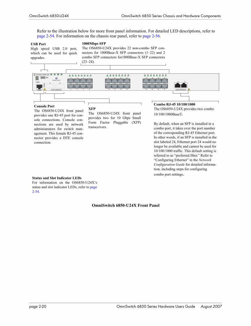
OmniSwitch 6850-U24X OmniSwitch 6850 Series Chassis and Hardware Components
Refer to the illustration below for more front panel information. For detailed LED descriptions, refer to page 2-54. For information on the chassis rear panel, refer to page 2-56.
OmniSwitch 6850-U24X Front Panel
Console PortThe OS6850-U24X front panelprovides one RJ-45 port for con-sole connections. Console con-nections are used by networkadministrators for switch man-agement. This female RJ-45 con-nector provides a DTE consoleconnection.
Status and Slot Indicator LEDsFor information on the OS6850-U24X’sstatus and slot indicator LEDs, refer to page2-54.
USB PortHigh speed USB 2.0 port,which can be used for quickupgrades.
Combo RJ-45 10/100/1000 The OS6850-U24X provides two combo 10/100/1000BaseT.
By default, when an SFP is installed in a combo port, it takes over the port number of the corresponding RJ-45 Ethernet port. In other words, if an SFP is installed in the slot labeled 24, Ethernet port 24 would no longer be available and cannot be used for 10/100/1000 traffic. This default setting is referred to as “preferred fiber.” Refer to “Configuring Ethernet” in the Network Configuration Guide for detailed informa-tion, including steps for configuring combo port settings.
XFP The OS6850-U24X front panelprovides two for 10 Gbps SmallForm Factor Pluggable (XFP)transceivers.
1000Mbps SFP The OS6850-U24X provides 22 non-combo SFP con-nectors for 1000Base-X SFP connectors (1–22) and 2combo SFP connectors for1000Base-X SFP connectors(23–24).
OmniSwitch 6850-U24X
USB
Console
OK PRI PWR BPS 1 2 3 4 5 6 7 8 9 10 11 12 13 14 15 16 17 18 19 20 21 22 23 24
25 26
26
25
CLASS 1 LASER PRODUCTCLASS 1 LASER PRODUCT
23 24
1 3 5 7
2 4 6 8
9 11 13 15
10 12 14 16
17 19 21 23
18 20 22 24
page 2-20 OmniSwitch 6850 Series Hardware Users Guide August 2007

OmniSwitch 6850 Series Chassis and Hardware Components OmniSwitch 6850-U24X
OS6850-U24X Specifications
Total unshared 1000Base-X SFP connectors per switch (1–22)
22
Total shared 1000Base-X SFP connectors per switch (23–24)
2
Total combo10/100/1000Base-T per switch (23–24)
2
Total XFP Connectors (25–26) 2
Total 1000Base-X SFP connec-tors per stack
192 (stack of eight switches)
Total combo 10/100/1000Base-T per stack
16 (stack of eight switches)
Power 126/120W (AC/DC) power supply
Flash memory size 64 MB
RAM memory size 256 MB SDRAM
Overall Width (rack-mount flanges included)
19 inches, approx.
Chassis Width (rack-mount flanges not included)
17.5 inches
Height 1.73 inches
Height (rack units) 1 RU
Chassis Depth 10.5 inches without power supplies installed;16.75 inches with power supplies installed
Weight 14 lbs (6.24 Kg), approx.
Humidity 5% to 90% Relative Humidity (Operating)0% to 95% Relative Humidity (Storage)
Operating Temperature 0 to 45 degrees, Celsius
Storage Temperature -20 to 70 degrees, Celsius
Altitude Operating altitude: sea level at 40 degrees, Celsius and 10000 feet at 0 degrees, CelsiusStorage altitude: sea level to 40000 feet
Standards supported 10/100/1000Base-T and 1000Base-X
Data rate (RJ-45) 10 or 100 Mbps (full or half duplex)1 Gigabit per second (full duplex)
Data rate (SFP) 100 and 1000 Mbps (full duplex)
Data rate (XFP) 10 Gigabits per second (full duplex)
Maximum frame size 9216 Bytes
Connections supported 10/100/1000base-T, 1000Base-X, 10GBASE-L
OmniSwitch 6850 Series Hardware Users Guide August 2007 page 2-21

OmniSwitch 6850-U24X OmniSwitch 6850 Series Chassis and Hardware Components
Cable supported(RJ-45)
10BaseT: unshielded twisted-pair (UTP)100BaseTX: unshielded twisted-pair (UTP), Category 5, EIA/TIA 568 or shielded twisted-pair (STP), Category 5, 100 ohm1000BaseT: unshielded twisted-pair (UTP), Category 5e
Maximum cable distance(RJ-45)
100 meters
OS6850-U24X Specifications
page 2-22 OmniSwitch 6850 Series Hardware Users Guide August 2007

OmniSwitch 6850 Series Chassis and Hardware Components OmniSwitch 6850-24
OmniSwitch 6850-24The OmniSwitch 6850-24 is a stackable edge/workgroup switch offering 20 unshared 10/100/1000 Base-T, as well as four combo individually configurable to be 10/100/1000 Base-T or 1000 Base-X high speed connections.
The front panel of the OS6850-24 chassis contains the following major components:
• System status and slot indicator LEDs
• (20) unshared 10/100/1000Base-T
• (4) shared combo 10/100/1000Base-T
• (4) Combo SFP connectors for 1000Base-X connections
• Console port (RJ-45)
• USB port (USB 2.0)
Note. USB 2.0 is not supported in this release.
OmniSwitch 6850 Series Hardware Users Guide August 2007 page 2-23
OmniSwitch 6850-24 OmniSwitch 6850 Series Chassis and Hardware Components
Refer to the illustration below for more front panel information. For detailed LED descriptions, refer to page 2-54. For information on the chassis rear panel, refer to page 2-56.
OmniSwitch 6850-24 Front Panel
OmniSwitch 6850-24
USB
OK PRI PWR BPS
Console CLASS 1 LASER PRODUCT
1 2 3 4 5 6 7 8 9 10 11 12 13 14 15 16 17 18 19 20 21 22 23 24
21 22 23 24
10/100/1000Mbps The OS6850-24 provides 20 fixed 0/100/1000BaseT non-combo (1–20)and 4 fixed 10/100/1000BaseT combo (21–24).These are auto-sensing and auto-MDIX and use RJ-45 connectors.
Console PortThe OS6850-24 front panel pro-vides one RJ-45 port for consoleconnections. Console connec-tions are used by network admin-istrators for switch management.This female RJ-45 connectorprovides a DTE console connec-tion.
Status and Slot Indicator LEDsFor information on the OS6850-24’sstatus and slot indicator LEDs, referto page 2-54.
USB PortHigh speed USB 2.0 port, whichcan be used for quick upgrades.
Combo SFP The OS6850-24 provides four combo SFP connectors for 1000Base-X high-speed con-nections.
By default, when an SFP is installed in a combo port, it takes over the port number of the corresponding RJ-45 Ethernet port. In other words, if an SFP is installed in the slot labeled 24, Ethernet port 24 would no longer be available and cannot be used for 10/100/1000 traffic. This default setting is referred to as “preferred fiber.” Refer to “Configuring Ethernet” in the Network Configuration Guide for detailed information, including steps for configuring combo port settings.
page 2-24 OmniSwitch 6850 Series Hardware Users Guide August 2007

OmniSwitch 6850 Series Chassis and Hardware Components OmniSwitch 6850-24
OS6850-24 Specifications
Total unshared 10/100/000Base-T per switch (1–20)
20
Total shared 10/100/1000Base-T combo per switch (21–24)
4
Total combo 1000Base-X combo SFP connectors per switch (21–24)
4
Total 10/100/1000Base-T per stack
192 (stack of eight switches)
Total combo SFP connectors per stack
32 (stack of eight switches)
Power 126/120W (AC/DC) power supply
Flash memory size 64 MB
RAM memory size 256 MB SDRAM
Overall Width (rack-mount flanges included)
19 inches, approx.
Chassis Width (rack-mount flanges not included)
17.5 inches
Height 1.73 inches
Height (rack units) 1 RU
Chassis Depth 10.5 inches without power supplies installed;16.75 inches with power supplies installed
Weight 14 lbs (6.24 Kg), approx.
Humidity 5% to 90% Relative Humidity (Operating)0% to 95% Relative Humidity (Storage)
Operating Temperature 0 to 45 degrees, Celsius
Storage Temperature -20 to 70 degrees, Celsius
Altitude Operating altitude: sea level at 40 degrees, Celsius and 10000 feet at 0 degrees, CelsiusStorage altitude: sea level to 40000 feet
Standards supported 802.3z, 802.3ab, 1000Base-T, IEEE 802.3u
Data rate (RJ-45) 10 or 100 Mbps (full or half duplex)1 Gigabit per second (full duplex)
Data rate (SFP) 1 Gigabit per second (full duplex)
Maximum frame size 9216 bytes
Connections supported 10/100/1000Base-T and 1000Base-X
Cable supported(RJ-45)
10BaseT: unshielded twisted-pair (UTP)100BaseTX: unshielded twisted-pair (UTP), Category 5, EIA/TIA 568 or shielded twisted-pair (STP), Category 5, 100 ohm1000BaseT: unshielded twisted-pair (UTP), Category 5e
OmniSwitch 6850 Series Hardware Users Guide August 2007 page 2-25

OmniSwitch 6850-24 OmniSwitch 6850 Series Chassis and Hardware Components
Maximum cable distance(RJ-45)
100 meters
OS6850-24 Specifications
page 2-26 OmniSwitch 6850 Series Hardware Users Guide August 2007

OmniSwitch 6850 Series Chassis and Hardware Components OmniSwitch 6850-48
OmniSwitch 6850-48The OmniSwitch 6850-48 is a stackable edge/workgroup switch offering 44 unshared 10/100/1000Base-T, as well as four combo individually configurable to 10/100/1000Base-T or 1000Base-X high speed connec-tions.
The front panel of the OS6850-48 chassis contains the following major components:
• System status and slot indicator LEDs
• (44) unshared 10/100/1000Base-T
• (4) shared combo 10/100/1000Base-T
• (4) Combo SFP connectors for 1000Base-X connections
• Console port (RJ-45)
• USB port (USB 2.0)
Note. USB 2.0 is not supported in this release.
OmniSwitch 6850 Series Hardware Users Guide August 2007 page 2-27
OmniSwitch 6850-48 OmniSwitch 6850 Series Chassis and Hardware Components
Refer to the illustration below for more front panel information. For detailed LED descriptions, refer to page 2-54. For information on the chassis rear panel, refer to page 2-56.
OmniSwitch 6850-48 Front Panel
10/100/1000Mbps The OS6850-48 provides 44 fixed 10/100/1000BaseT(5–48) and 4 fixed 10/100/1000BaseT combo (1–4).These are auto-sensing and auto-MDIX and use RJ-45connectors.
Console PortThe OS6850-48 front panel provides oneRJ-45 port for console connections. Con-sole connections are used by networkadministrators for switch management.This female RJ-45 connector provides aDTE console connection.
Status and Slot Indicator LEDsFor detailed information on OS6850-48status and slot indicator LEDs, refer topage 2-54.
OmniSwitch 6850-48
USB
Console
OK PRI PWR BPS
CLASS 1 LASER PRODUCT1 2 3 4
1 2 3 4 5 6 7 8 9 10 11 12 13 14 15 16 17 18 19 20 21 22 23 24 25 26 27 28 29 30 31 32 33 34 35 36 37 38 39 40 41 42 43 44 45 46 47 48
USB PortHigh speed (480 Mbps) USB 2.0port, which can be used for quickupgrades.
Combo SFP The OS6850-48 provides four combo SFP connectors for 1000Base-X high-speed connections.
By default, when an SFP is installed in a combo port, it takes over the port num-ber of the corresponding RJ-45 Ethernet port. In other words, if an SFP is installed in the slot labeled 4, Ethernet port 4 is no longer available and cannot be used for 10/100/1000 traffic. This default setting is referred to as “preferred fiber.” Refer to “Configuring Ethernet” in the Network Configuration Guide for detailed information, including steps for configuring combo port settings.
page 2-28 OmniSwitch 6850 Series Hardware Users Guide August 2007

OmniSwitch 6850 Series Chassis and Hardware Components OmniSwitch 6850-48
OS6850-48 Specifications
Total unshared 10/100/1000Base-T per switch (5–48)
44
Total shared 10/100/1000Base-T combo per switch (1–4)
4
Total combo SFP connectors per switch (1–4)
4
Total 10/100/1000Base-T per stack
384 (stack of eight switches)
Total combo SFP connectors per stack
32 (stack of eight switches)
Power 126/120W (AC/DC) power supply
Flash memory size 64 MB
RAM memory size 256 MB SDRAM
Overall Width (rack-mount flanges included)
19 inches, approx.
Chassis Width (rack-mount flanges not included)
17.5 inches
Height 1.73 inches
Height (rack units) 1 RU
Chassis Depth 10.5 inches without power supplies installed;16.75 inches with power supplies installed
Weight 14 lbs (6.24 Kg), approx.
Humidity 5% to 90% Relative Humidity (Operating)0% to 95% Relative Humidity (Storage)
Operating Temperature 0 to 45 degrees, Celsius
Storage Temperature -20 to 70 degrees, Celsius
Altitude Operating altitude: sea level at 40 degrees, Celsius and 10000 feet at 0 degrees, CelsiusStorage altitude: sea level to 40000 feet
Standards supported 802.3z, 802.3ab, 1000Base-T, IEEE 802.3u
Data rate (RJ-45) 10 or 100 Mbps (full or half duplex)1 Gigabit per second (full duplex)
Data rate (SFP) 1 Gigabit per second (full duplex)
Maximum frame size 9216
Connections supported 10/100/1000Base-T and 1000Base-X
Cable supported(RJ-45)
10BaseT: unshielded twisted-pair (UTP)100BaseTX: unshielded twisted-pair (UTP), Category 5, EIA/TIA 568 or shielded twisted-pair (STP), Category 5, 100 ohm1000BaseT: unshielded twisted-pair (UTP), Category 5e
OmniSwitch 6850 Series Hardware Users Guide August 2007 page 2-29

OmniSwitch 6850-48 OmniSwitch 6850 Series Chassis and Hardware Components
Maximum cable distance(RJ-45)
100 meters
OS6850-48 Specifications
page 2-30 OmniSwitch 6850 Series Hardware Users Guide August 2007

OmniSwitch 6850 Series Chassis and Hardware Components OmniSwitch 6850-24X
OmniSwitch 6850-24XThe OmniSwitch 6850-24X is a stackable edge/workgroup switch offering 20 unshared 10/100/1000 Base-T Power over, two (2) 10 Gigabit XFP connectors, as well as four combo individually configurable to 10/100/1000 Base-T or 1000 Base-X high speed connections.
The front panel of the OS6850-24X chassis contains the following major components:
• System status and slot indicator LEDs
• (20) unshared 10/100/1000Base-T
• (4) shared combo 10/100/1000Base-T
• (4) Combo SFP connectors for 1000Base-X connections
• (2) 10 Gigabit XFP connectors
• Console port (RJ-45)
• USB port (USB 2.0)
Note. USB 2.0 is not supported in this release.
OmniSwitch 6850 Series Hardware Users Guide August 2007 page 2-31
OmniSwitch 6850-24X OmniSwitch 6850 Series Chassis and Hardware Components
Refer to the illustration below for more front panel information. For detailed LED descriptions, refer to page 2-54. For information on the chassis rear panel, refer to page 2-56.
OmniSwitch 6850-24X Front Panel
Console PortThe OS6850-24X front panelprovides one RJ-45 port for con-sole connections. Console con-nections are used by networkadministrators for switch man-agement. This female RJ-45 con-nector provides a DTE consoleconnection.
Status and Slot Indicator LEDsFor information on the OS6850-24X’sstatus and slot indicator LEDs, refer topage 2-54.
USB PortHigh speed USB 2.0 port,which can be used for quickupgrades.
Combo SFP The OS6850-24X provides four combo SFP connectors for 1000Base-X high-speed connections.
By default, when an SFP is installed in a combo port, it takes over the port number of the corresponding RJ-45 Ethernet port. In other words, if an SFP is installed in the slot labeled 24, Ethernet port 24 would no longer be available and cannot be used for 10/100/1000 traffic. This default setting is referred to as “preferred fiber.” Refer to “Configuring Ethernet” in the Network Configuration Guide for detailed information, including steps for configuring combo port settings.
XFP The OS6850-24X front panel providestwo for 10 Gbps Small Form FactorPluggable (XFP) transceivers.
OmniSwitch 6850-24X
USB
Console
OK PRI PWR BPS1 2 3 4 5 6 7 8 9 10 11 12 13 14 15 16 17 18 19 20 21 22 23 24
25 26
26
25
CLASS 1 LASER PRODUCTCLASS 1 LASER PRODUCT
21 22 23 24
10/100/1000Mbps The OS6850-24X provides 20 fixed 10/100/1000BaseTnon-combo (1–20) and 4 fixed10/100/1000BaseT combo (21–24). These are auto-sensing and auto-MDIX and use RJ-45 connectors.
page 2-32 OmniSwitch 6850 Series Hardware Users Guide August 2007

OmniSwitch 6850 Series Chassis and Hardware Components OmniSwitch 6850-24X
OS6850-24X Specifications
Total unshared 10/100/1000Base-T per switch (1–20)
20
Total shared 10/100/1000Base-T combo per switch (21–24)
4
Total combo 1000Base-X combo SFP connectors per switch (21–24)
4
Total XFP Connectors (25–26) 2
Total 10/100/1000Base-T per stack
192 (stack of eight switches)
Total combo SFP connectors per stack
32 (stack of eight switches)
Power 126/120W (AC/DC) power supply
Flash memory size 64 MB
RAM memory size 256 MB SDRAM
Overall Width (rack-mount flanges included)
19 inches, approx.
Chassis Width (rack-mount flanges not included)
17.5 inches
Height 1.73 inches
Height (rack units) 1 RU
Chassis Depth 10.5 inches without power supplies installed;16.75 inches with power supplies installed
Weight 14 lbs (6.24 Kg), approx.
Humidity 5% to 90% Relative Humidity (Operating)0% to 95% Relative Humidity (Storage)
Operating Temperature 0 to 45 degrees, Celsius
Storage Temperature -20 to 70 degrees, Celsius
Altitude Operating altitude: sea level at 40 degrees, Celsius and 10000 feet at 0 degrees, CelsiusStorage altitude: sea level to 40000 feet
Standards supported 10/100/1000Base-T and 1000Base-X
Data rate (RJ-45) 10 or 100 Mbps (full or half duplex)1 Gigabit per second (full duplex)
Data rate (SFP) 1 Gigabit per second (full duplex)
Data rate (XFP) 10 Gigabits per second (full duplex)
Maximum frame size 9216 Bytes
Connections supported 10/100/1000base-T, 1000Base-X, 10GBASE-L
OmniSwitch 6850 Series Hardware Users Guide August 2007 page 2-33

OmniSwitch 6850-24X OmniSwitch 6850 Series Chassis and Hardware Components
Cable supported(RJ-45)
10BaseT: unshielded twisted-pair (UTP)100BaseTX: unshielded twisted-pair (UTP), Category 5, EIA/TIA 568 or shielded twisted-pair (STP), Category 5, 100 ohm1000BaseT: unshielded twisted-pair (UTP), Category 5e
Maximum cable distance(RJ-45)
100 meters
OS6850-24X Specifications
page 2-34 OmniSwitch 6850 Series Hardware Users Guide August 2007

OmniSwitch 6850 Series Chassis and Hardware Components OmniSwitch 6850-48X
OmniSwitch 6850-48XThe OmniSwitch 6850-48X is a stackable edge/workgroup switch offering 48 unshared 10/100/1000Base T and two (2) 10 Gigabit XFP connectors.
The front panel of the OS6850-48X chassis contains the following major components:
• System status and slot indicator LEDs
• (48) unshared 10/100/1000Base-T
• (2) 10 Gigabit XFP connectors
• Console port (RJ-45)
• USB port (USB 2.0)
Note. USB 2.0 is not supported in this release.
OmniSwitch 6850 Series Hardware Users Guide August 2007 page 2-35
OmniSwitch 6850-48X OmniSwitch 6850 Series Chassis and Hardware Components
Refer to the illustration below for more front panel information. For detailed LED descriptions, refer to page 2-54. For information on the chassis rear panel, refer to page 2-56.
OmniSwitch 6850-48X Front Panel
10/100/1000Mbps The OS6850-48X provides 48 fixed 10/100/1000BaseT non-combo (1–48). Theseare auto-sensing and auto-MDIX and useRJ-45 connectors.
Console PortThe front panel provides one RJ-45 port for console connections.Console connections are used bynetwork administrators forswitch management. This femaleRJ-45 connector provides a DTEconsole connection.
Status and Slot Indicator LEDsFor information on the OS6850-48X’sstatus and slot indicator LEDs, refer topage 2-54.
USB PortHigh speed USB 2.0 port, whichcan be used for quick upgrades.
XFP The OS6850-48X front panel pro-vides two for 10 Gbps Small FormFactor Pluggable (XFP) transceiv-ers.
OmniSwitch 6850-48X
USB
Console CLASS 1 LASER PRODUCT
OK PRI PWR BPS
49
50
49 50
1 2 3 4 5 6 7 8 9 10 11 12 13 14 15 16 17 18 19 20 21 22 23 24 25 26 27 28 29 30 31 32 33 34 35 36 37 38 39 40 41 42 43 44 45 46 47 48
page 2-36 OmniSwitch 6850 Series Hardware Users Guide August 2007

OmniSwitch 6850 Series Chassis and Hardware Components OmniSwitch 6850-48X
OS6850-48X Specifications
Total unshared 10/100/1000Base-T per switch (1–48)
48
Total XFP Connectors (49–50) 2
Total 10/100/1000Base-T per stack
384 (stack of eight switches)
Power 126/120W (AC/DC) power supply
Flash memory size 64 MB
RAM memory size 256 MB SDRAM
Overall Width (rack-mount flanges included)
19 inches, approx.
Chassis Width (rack-mount flanges not included)
17.5 inches
Height 1.73 inches
Height (rack units) 1 RU
Chassis Depth 10.5 inches without power supplies installed;16.75 inches with power supplies installed
Weight 14 lbs (6.24 Kg), approx.
Humidity 5% to 90% Relative Humidity (Operating)0% to 95% Relative Humidity (Storage)
Operating Temperature 0 to 45 degrees, Celsius
Storage Temperature -20 to 70 degrees, Celsius
Altitude Operating altitude: sea level at 40 degrees, Celsius and 10000 feet at 0 degrees, CelsiusStorage altitude: sea level to 40000 feet
Standards supported 802.3z, 802.3ab, 1000Base-T, IEEE 802.3u,
Data rate (RJ-45) 10 or 100 Mbps (full or half duplex)1 Gigabit per second (full duplex)
Data rate (SFP) 1 Gigabit per second (full duplex)
Data rate (XFP) 10 Gigabits per second (full duplex)
Maximum frame size 9216 Bytes
Connections supported 10/100/1000Base-T, 1000Base-X, 10GBASE-L
Cable supported(RJ-45)
10BaseT: unshielded twisted-pair (UTP)100BaseTX: unshielded twisted-pair (UTP), Category 5, EIA/TIA 568 or shielded twisted-pair (STP), Category 5, 100 ohm1000BaseT: unshielded twisted-pair (UTP), Category 5e
Maximum cable distance(RJ-45) RJ-45
100 meters
OmniSwitch 6850 Series Hardware Users Guide August 2007 page 2-37

OmniSwitch 6850-P24 OmniSwitch 6850 Series Chassis and Hardware Components
OmniSwitch 6850-P24The OmniSwitch 6850-P24 is a stackable edge/workgroup switch offering 20 unshared 10/100/1000 Base-T Power over Ethernet (PoE), as well as four combo individually configurable to 10/100/1000 Base-T PoE or 1000 Base-X high speed connections.
The front panel of the OS6850-P24 chassis contains the following major components:
• System status and slot indicator LEDs
• (20) unshared 10/100/1000Base-T PoE
• (4) shared combo 10/100/1000Base-T PoE
• (4) Combo SFP connectors for 1000Base-X connections
• Console port (RJ-45)
• USB port (USB 2.0)
Note. USB 2.0 is not supported in this release.
page 2-38 OmniSwitch 6850 Series Hardware Users Guide August 2007
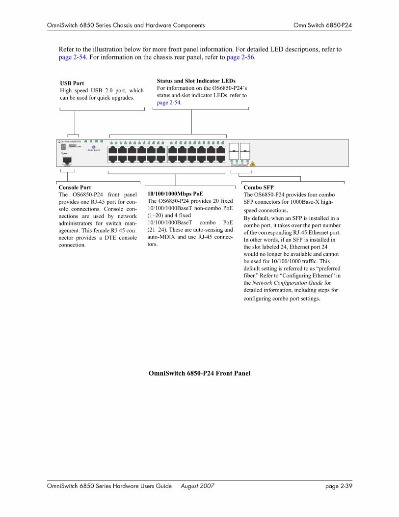
OmniSwitch 6850 Series Chassis and Hardware Components OmniSwitch 6850-P24
Refer to the illustration below for more front panel information. For detailed LED descriptions, refer to page 2-54. For information on the chassis rear panel, refer to page 2-56.
OmniSwitch 6850-P24 Front Panel
10/100/1000Mbps PoE The OS6850-P24 provides 20 fixed10/100/1000BaseT non-combo PoE(1–20) and 4 fixed10/100/1000BaseT combo PoE(21–24). These are auto-sensing andauto-MDIX and use RJ-45 connec-tors.
Console PortThe OS6850-P24 front panelprovides one RJ-45 port for con-sole connections. Console con-nections are used by networkadministrators for switch man-agement. This female RJ-45 con-nector provides a DTE consoleconnection.
Status and Slot Indicator LEDsFor information on the OS6850-P24’sstatus and slot indicator LEDs, refer topage 2-54.
USB PortHigh speed USB 2.0 port, whichcan be used for quick upgrades.
Combo SFP The OS6850-P24 provides four combo SFP connectors for 1000Base-X high-speed connections.By default, when an SFP is installed in a combo port, it takes over the port number of the corresponding RJ-45 Ethernet port. In other words, if an SFP is installed in the slot labeled 24, Ethernet port 24 would no longer be available and cannot be used for 10/100/1000 traffic. This default setting is referred to as “preferred fiber.” Refer to “Configuring Ethernet” in the Network Configuration Guide for detailed information, including steps for configuring combo port settings.
OmniSwitch 6850-P24
USB
OK PRI PWR BPS
Console CLASS 1 LASER PRODUCT
1 2 3 4 5 6 7 8 9 10 11 12 13 14 15 16 17 18 19 20 21 22 23 24
21 22 23 24
OmniSwitch 6850 Series Hardware Users Guide August 2007 page 2-39

OmniSwitch 6850-P24 OmniSwitch 6850 Series Chassis and Hardware Components
OS6850-P24 Specifications
Total unshared 10/100/1000Base-T PoE per switch (1–20)
20
Total shared 10/100/1000Base-T PoE combo per switch (21–24)
4
Total combo 1000Base-X combo SFP connectors per switch (21–24)
4
Total 10/100/1000Base-T PoE per stack
192 (stack of eight switches)
Total combo SFP connectors per stack
32 (stack of eight switches)
Power 510/360W power supply
Flash memory size 64 MB
RAM memory size 256 MB SDRAM
Overall Width (rack-mount flanges included)
19 inches, approx.
Chassis Width (rack-mount flanges not included)
17.5 inches
Height 1.73 inches
Height (rack units) 1 RU
Chassis Depth 10.5 inches without power supplies installed;16.75 inches with power supplies installed
Weight 14 lbs (6.24 Kg), approx.
Humidity 5% to 90% Relative Humidity (Operating)0% to 95% Relative Humidity (Storage)
Operating Temperature 0 to 45 degrees, Celsius
Storage Temperature -20 to 70 degrees, Celsius
Altitude Operating altitude: sea level at 40 degrees, Celsius and 10000 feet at 0 degrees, CelsiusStorage altitude: sea level to 40000 feet
Standards supported 802.3z, 802.3ab, 1000Base-T, IEEE 802.3u, 802.3af (DTE Power via MDI MIB); IAB RFCs 826, 894
Data rate (RJ-45) 10 or 100 Mbps (full or half duplex)1 Gigabit per second (full duplex)
Data rate (SFP) 1 Gigabit per second (full duplex)
Maximum frame size 9216 bytes
Connections supported IP phones, Bluetooth Access Points, Internet cameras, and other devices requiring power over Ethernet
page 2-40 OmniSwitch 6850 Series Hardware Users Guide August 2007

OmniSwitch 6850 Series Chassis and Hardware Components OmniSwitch 6850-P24
Cable supported(RJ-45)
10BaseT: unshielded twisted-pair (UTP)100BaseTX: unshielded twisted-pair (UTP), Category 5, EIA/TIA 568 or shielded twisted-pair (STP), Category 5, 100 ohm1000BaseT: unshielded twisted-pair (UTP), Category 5e
Power supplied to port 15.4 watts per port
Maximum cable distance(RJ-45)
100 meters
OS6850-P24 Specifications
OmniSwitch 6850 Series Hardware Users Guide August 2007 page 2-41

OmniSwitch 6850-P48 OmniSwitch 6850 Series Chassis and Hardware Components
OmniSwitch 6850-P48The OmniSwitch 6850-P48 is a stackable edge/workgroup switch offering 44 unshared10/100/1000 Base-T Power over Ethernet (PoE), as well as four combo individually configurable to 10/100/1000 Base-T PoE or 1000 Base-X high speed connections.
The front panel of the OS6850-P48 chassis contains the following major components:
• System status and slot indicator LEDs
• (44) unshared 10/100/1000Base-T PoE
• (4) shared combo 10/100/1000Base-T PoE
• (4) Combo SFP connectors for 1000Base-X connections
• Console port (RJ-45)
• USB port (USB 2.0)
Note. USB 2.0 is not supported in this release.
page 2-42 OmniSwitch 6850 Series Hardware Users Guide August 2007
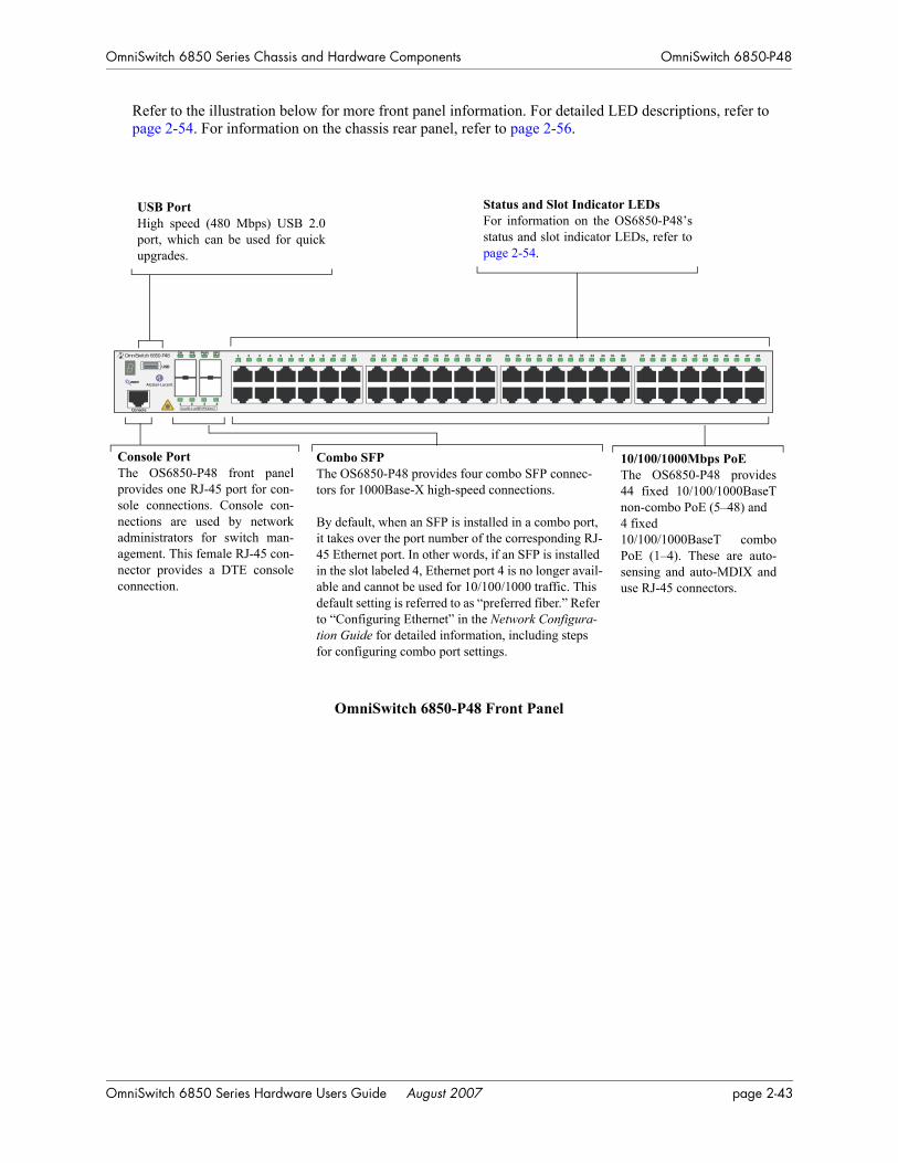
OmniSwitch 6850 Series Chassis and Hardware Components OmniSwitch 6850-P48
Refer to the illustration below for more front panel information. For detailed LED descriptions, refer to page 2-54. For information on the chassis rear panel, refer to page 2-56.
OmniSwitch 6850-P48 Front Panel
10/100/1000Mbps PoE The OS6850-P48 provides44 fixed 10/100/1000BaseTnon-combo PoE (5–48) and 4 fixed10/100/1000BaseT comboPoE (1–4). These are auto-sensing and auto-MDIX anduse RJ-45 connectors.
Console PortThe OS6850-P48 front panelprovides one RJ-45 port for con-sole connections. Console con-nections are used by networkadministrators for switch man-agement. This female RJ-45 con-nector provides a DTE consoleconnection.
Status and Slot Indicator LEDsFor information on the OS6850-P48’sstatus and slot indicator LEDs, refer topage 2-54.
USB PortHigh speed (480 Mbps) USB 2.0port, which can be used for quickupgrades.
OmniSwitch 6850-P48
USB
OK PRI PWR BPS
Console CLASS 1 LASER PRODUCT1 2 3 4
1 2 3 4 5 6 7 8 9 10 11 12 13 14 15 16 17 18 19 20 21 22 23 24 25 26 27 28 29 30 31 32 33 34 35 36 37 38 39 40 41 42 43 44 45 46 47 48
Combo SFP The OS6850-P48 provides four combo SFP connec-tors for 1000Base-X high-speed connections.
By default, when an SFP is installed in a combo port, it takes over the port number of the corresponding RJ-45 Ethernet port. In other words, if an SFP is installed in the slot labeled 4, Ethernet port 4 is no longer avail-able and cannot be used for 10/100/1000 traffic. This default setting is referred to as “preferred fiber.” Refer to “Configuring Ethernet” in the Network Configura-tion Guide for detailed information, including steps for configuring combo port settings.
OmniSwitch 6850 Series Hardware Users Guide August 2007 page 2-43

OmniSwitch 6850-P48 OmniSwitch 6850 Series Chassis and Hardware Components
OS6850-P48 Specifications
Total unshared 10/100/1000Base-T PoE per switch (5–48)
44
Total shared 10/100/1000Base-T PoE combo per switch (1–4)
4
Total combo 1000Base-X combo SFP connectors per switch (1–4)
4
Total 10/100/1000Base-T PoE per stack
384 (stack of eight switches)
Total combo SFP connectors per stack
32 (stack of eight switches)
Power 510/360W power supply
Flash memory size 64 MB
RAM memory size 256 MB SDRAM
Overall Width (rack-mount flanges included)
19 inches, approx.
Chassis Width (rack-mount flanges not included)
17.5 inches
Height 1.73 inches
Height (rack units) 1 RU
Chassis Depth 10.5 inches without power supplies installed;16.75 inches with power supplies installed
Weight 14 lbs (6.24 Kg), approx.
Humidity 5% to 90% Relative Humidity (Operating)0% to 95% Relative Humidity (Storage)
Operating Temperature 0 to 45 degrees, Celsius
Storage Temperature -20 to 70 degrees, Celsius
Altitude Operating altitude: sea level at 40 degrees, Celsius and 10000 feet at 0 degrees, CelsiusStorage altitude: sea level to 40000 feet
Standards supported 802.3z, 802.3ab, 1000Base-T, IEEE 802.3u, 802.3af (DTE Power via MDI MIB); IAB RFCs 826, 894
Data rate (RJ-45) 10 or 100 Mbps (full or half duplex)1 Gigabit per second (full duplex)
Data rate (SFP) 1 Gigabit per second (full duplex)
Maximum frame size 9216
Connections supported IP phones, Bluetooth Access Points, Internet cameras, and other devices requiring power over Ethernet
page 2-44 OmniSwitch 6850 Series Hardware Users Guide August 2007

OmniSwitch 6850 Series Chassis and Hardware Components OmniSwitch 6850-P48
Cable supported(RJ-45)
10BaseT: unshielded twisted-pair (UTP)100BaseTX: unshielded twisted-pair (UTP), Category 5, EIA/TIA 568 or shielded twisted-pair (STP), Category 5, 100 ohm1000BaseT: unshielded twisted-pair (UTP), Category 5e
Power supplied to port 15.4 watts per port
Maximum cable distance(RJ-45)
100 meters
OS6850-P48 Specifications
OmniSwitch 6850 Series Hardware Users Guide August 2007 page 2-45

OmniSwitch 6850-P24X OmniSwitch 6850 Series Chassis and Hardware Components
OmniSwitch 6850-P24XThe OmniSwitch 6850-P24X is a stackable edge/workgroup switch offering 20 unshared 10/100/1000 Base-T Power over Ethernet (PoE), two (2) 10 Gigabit XFP connectors, as well as four combo individu-ally configurable to 10/100/1000 Base-T PoE or 1000 Base-X high speed connections.
The front panel of the OS6850-P24X chassis contains the following major components:
• System status and slot indicator LEDs
• (20) unshared 10/100/1000Base-T PoE
• (4) shared combo 10/100/1000Base-T PoE
• (4) Combo SFP connectors for 1000Base-X connections
• (2) 10 Gigabit XFP connectors
• Console port (RJ-45)
• USB port (USB 2.0)
Note. USB 2.0 is not supported in this release.
page 2-46 OmniSwitch 6850 Series Hardware Users Guide August 2007
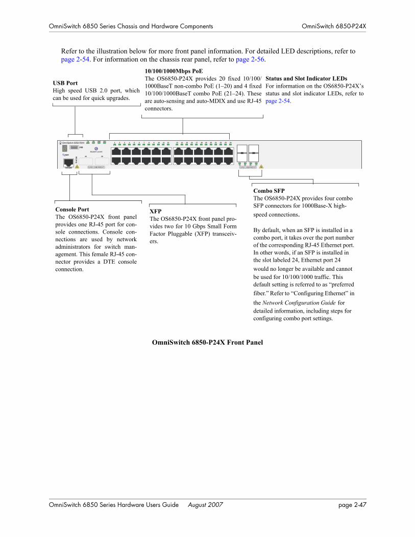
OmniSwitch 6850 Series Chassis and Hardware Components OmniSwitch 6850-P24X
Refer to the illustration below for more front panel information. For detailed LED descriptions, refer to page 2-54. For information on the chassis rear panel, refer to page 2-56.
OmniSwitch 6850-P24X Front Panel
Console PortThe OS6850-P24X front panelprovides one RJ-45 port for con-sole connections. Console con-nections are used by networkadministrators for switch man-agement. This female RJ-45 con-nector provides a DTE consoleconnection.
Status and Slot Indicator LEDsFor information on the OS6850-P24X’sstatus and slot indicator LEDs, refer topage 2-54.
USB PortHigh speed USB 2.0 port, whichcan be used for quick upgrades.
XFP The OS6850-P24X front panel pro-vides two for 10 Gbps Small FormFactor Pluggable (XFP) transceiv-ers.
OmniSwitch 6850-P24X
USB
Console
OK PRI PWR BPS1 2 3 4 5 6 7 8 9 10 11 12 13 14 15 16 17 18 19 20 21 22 23 24
25 26
26
25
CLASS 1 LASER PRODUCTCLASS 1 LASER PRODUCT
21 22 23 24
Combo SFP The OS6850-P24X provides four combo SFP connectors for 1000Base-X high-speed connections.
By default, when an SFP is installed in a combo port, it takes over the port number of the corresponding RJ-45 Ethernet port. In other words, if an SFP is installed in the slot labeled 24, Ethernet port 24 would no longer be available and cannot be used for 10/100/1000 traffic. This default setting is referred to as “preferred fiber.” Refer to “Configuring Ethernet” in the Network Configuration Guide for detailed information, including steps for configuring combo port settings.
10/100/1000Mbps PoE The OS6850-P24X provides 20 fixed 10/100/1000BaseT non-combo PoE (1–20) and 4 fixed10/100/1000BaseT combo PoE (21–24). Theseare auto-sensing and auto-MDIX and use RJ-45connectors.
OmniSwitch 6850 Series Hardware Users Guide August 2007 page 2-47

OmniSwitch 6850-P24X OmniSwitch 6850 Series Chassis and Hardware Components
OS6850-P24X Specifications
Total unshared 10/100/1000Base-T PoE per switch (1–20)
20
Total shared 10/100/1000Base-T PoE combo per switch (21–24)
4
Total combo 1000Base-X combo SFP connectors per switch (21–24)
4
Total XFP Connectors (25–26) 2
Total 10/100/1000Base-T PoE per stack
192 (stack of eight switches)
Total combo SFP connectors per stack
32 (stack of eight switches)
Power 510/360W power supply
Flash memory size 64 MB
RAM memory size 256 MB SDRAM
Overall Width (rack-mount flanges included)
19 inches, approx.
Chassis Width (rack-mount flanges not included)
17.5 inches
Height 1.73 inches
Height (rack units) 1 RU
Chassis Depth 10.5 inches without power supplies installed;16.75 inches with power supplies installed
Weight 14 lbs (6.24 Kg), approx.
Humidity 5% to 90% Relative Humidity (Operating)0% to 95% Relative Humidity (Storage)
Operating Temperature 0 to 45 degrees, Celsius
Storage Temperature -20 to 70 degrees, Celsius
Altitude Operating altitude: sea level at 40 degrees, Celsius and 10000 feet at 0 degrees, CelsiusStorage altitude: sea level to 40000 feet
Standards supported 802.3z, 802.3ab, 1000Base-T, IEEE 802.3u, 802.3af (DTE Power via MDI MIB); IAB RFCs 826, 894
Data rate (RJ-45) 10 or 100 Mbps (full or half duplex)1 Gigabit per second (full duplex)
Data rate (SFP) 1 Gigabit per second (full duplex)
Data rate (XFP) 10 Gigabits per second (full duplex)
Maximum frame size 9216 Bytes
page 2-48 OmniSwitch 6850 Series Hardware Users Guide August 2007

OmniSwitch 6850 Series Chassis and Hardware Components OmniSwitch 6850-P24X
Connections supported IP phones, Bluetooth Access Points, Internet cameras, and other devices requiring power over Ethernet
Cable supported(RJ-45)
10BaseT: unshielded twisted-pair (UTP)100BaseTX: unshielded twisted-pair (UTP), Category 5, EIA/TIA 568 or shielded twisted-pair (STP), Category 5, 100 ohm1000BaseT: unshielded twisted-pair (UTP), Category 5e
Power supplied to port 15.4 watts per port
Maximum cable distance(RJ-45)
100 meters
OS6850-P24X Specifications
OmniSwitch 6850 Series Hardware Users Guide August 2007 page 2-49

OmniSwitch 6850-P48X OmniSwitch 6850 Series Chassis and Hardware Components
OmniSwitch 6850-P48XThe OmniSwitch 6850-P48X is a stackable edge/workgroup switch offering 48 unshared 10/100/1000Base-T Power over Ethernet (PoE) and two (2) 10 Gigabit XFP connectors.
The front panel of the OS6850-P48X chassis contains the following major components:
• System status and slot indicator LEDs
• (48) unshared 10/100/1000Base-T PoE
• (2) 10 Gigabit XFP connectors
• Console port (RJ-45)
• USB port (USB 2.0)
Note. USB 2.0 is not supported in this release.
page 2-50 OmniSwitch 6850 Series Hardware Users Guide August 2007
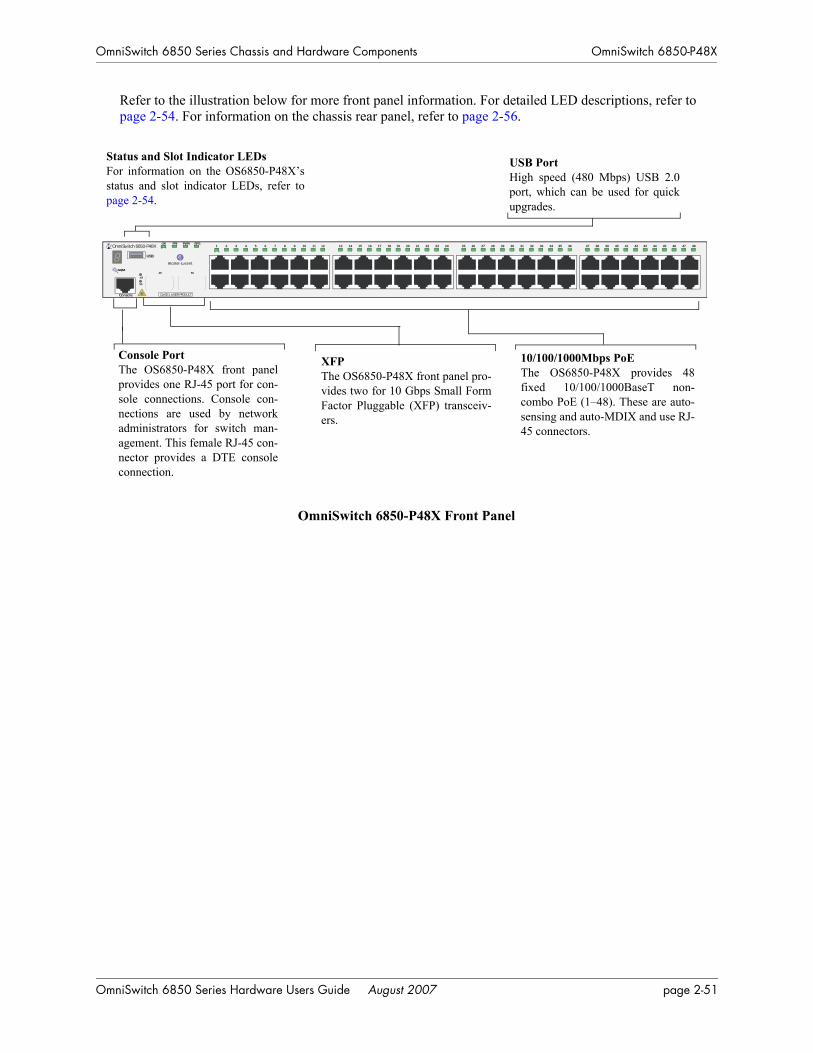
OmniSwitch 6850 Series Chassis and Hardware Components OmniSwitch 6850-P48X
Refer to the illustration below for more front panel information. For detailed LED descriptions, refer to page 2-54. For information on the chassis rear panel, refer to page 2-56.
OmniSwitch 6850-P48X Front Panel
OmniSwitch 6850-P48X
USB
Console CLASS 1 LASER PRODUCT
OK PRI PWR BPS
49
50
49 50
1 2 3 4 5 6 7 8 9 10 11 12 13 14 15 16 17 18 19 20 21 22 23 24 25 26 27 28 29 30 31 32 33 34 35 36 37 38 39 40 41 42 43 44 45 46 47 48
10/100/1000Mbps PoE The OS6850-P48X provides 48fixed 10/100/1000BaseT non-combo PoE (1–48). These are auto-sensing and auto-MDIX and use RJ-45 connectors.
Console PortThe OS6850-P48X front panelprovides one RJ-45 port for con-sole connections. Console con-nections are used by networkadministrators for switch man-agement. This female RJ-45 con-nector provides a DTE consoleconnection.
Status and Slot Indicator LEDsFor information on the OS6850-P48X’sstatus and slot indicator LEDs, refer topage 2-54.
USB PortHigh speed (480 Mbps) USB 2.0port, which can be used for quickupgrades.
XFP The OS6850-P48X front panel pro-vides two for 10 Gbps Small FormFactor Pluggable (XFP) transceiv-ers.
OmniSwitch 6850 Series Hardware Users Guide August 2007 page 2-51

OmniSwitch 6850-P48X OmniSwitch 6850 Series Chassis and Hardware Components
OS6850-P48X Specifications
Total unshared 10/100/1000Base-T PoE per switch (1–48)
48
Total XFP Connectors (49–50) 2
Total 10/100/1000Base-T PoE per stack
384 (stack of eight switches)
Power 510/360W power supply
Flash memory size 64 MB
RAM memory size 256 MB SDRAM
Overall Width (rack-mount flanges included)
19 inches, approx.
Chassis Width (rack-mount flanges not included)
17.5 inches
Height 1.73 inches
Height (rack units) 1 RU
Chassis Depth 10.5 inches without power supplies installed;16.75 inches with power supplies installed
Weight 14 lbs (6.24 Kg), approx.
Humidity 5% to 90% Relative Humidity (Operating)0% to 95% Relative Humidity (Storage)
Operating Temperature 0 to 45 degrees, Celsius
Storage Temperature -20 to 70 degrees, Celsius
Altitude Operating altitude: sea level at 40 degrees, Celsius and 10000 feet at 0 degrees, CelsiusStorage altitude: sea level to 40000 feet
Standards supported 802.3z, 802.3ab, 1000Base-T, IEEE 802.3u, 802.3af (DTE Power via MDI MIB); IAB RFCs 826, 894
Data rate (RJ-45) 10 or 100 Mbps (full or half duplex)1 Gigabit per second (full duplex)
Data rate (SFP) 1 Gigabit per second (full duplex)
Data rate (XFP) 10 Gigabits per second (full duplex)
Maximum frame size 9216 Bytes
Connections supported IP phones, Bluetooth Access Points, Internet cameras, and other devices requiring power over Ethernet
Cable supported(RJ-45)
10BaseT: unshielded twisted-pair (UTP)100BaseTX: unshielded twisted-pair (UTP), Category 5, EIA/TIA 568 or shielded twisted-pair (STP), Category 5, 100 ohm1000BaseT: unshielded twisted-pair (UTP), Category 5e
Power supplied to port 15.4 watts per port
page 2-52 OmniSwitch 6850 Series Hardware Users Guide August 2007

OmniSwitch 6850 Series Chassis and Hardware Components OmniSwitch 6850-P48X
Maximum cable distance(RJ-45) RJ-45
100 meters
OS6850-P48X Specifications
OmniSwitch 6850 Series Hardware Users Guide August 2007 page 2-53
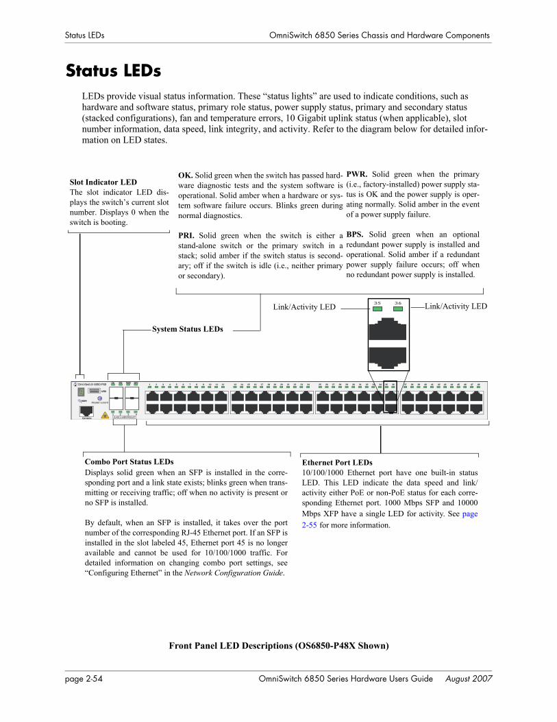
Status LEDs OmniSwitch 6850 Series Chassis and Hardware Components
Status LEDsLEDs provide visual status information. These “status lights” are used to indicate conditions, such as hardware and software status, primary role status, power supply status, primary and secondary status (stacked configurations), fan and temperature errors, 10 Gigabit uplink status (when applicable), slot number information, data speed, link integrity, and activity. Refer to the diagram below for detailed infor-mation on LED states.
Front Panel LED Descriptions (OS6850-P48X Shown)
Displays solid green when an SFP is installed in the corre-sponding port and a link state exists; blinks green when trans-mitting or receiving traffic; off when no activity is present orno SFP is installed.
By default, when an SFP is installed, it takes over the portnumber of the corresponding RJ-45 Ethernet port. If an SFP isinstalled in the slot labeled 45, Ethernet port 45 is no longeravailable and cannot be used for 10/100/1000 traffic. Fordetailed information on changing combo port settings, see“Configuring Ethernet” in the Network Configuration Guide.
OmniSwitch 6850-P48
USB
OK PRI PWR BPS
Console CLASS 1 LASER PRODUCT1 2 3 4
1 2 3 4 5 6 7 8 9 10 11 12 13 14 15 16 17 18 19 20 21 22 23 24 25 26 27 28 29 30 31 32 33 34 35 36 37 38 39 40 41 42 43 44 45 46 47 48
Slot Indicator LEDThe slot indicator LED dis-plays the switch’s current slotnumber. Displays 0 when theswitch is booting.
Ethernet Port LEDs10/100/1000 Ethernet port have one built-in statusLED. This LED indicate the data speed and link/activity either PoE or non-PoE status for each corre-sponding Ethernet port. 1000 Mbps SFP and 10000Mbps XFP have a single LED for activity. See page2-55 for more information.
Link/Activity LEDLink/Activity LED
Combo Port Status LEDs
OK. Solid green when the switch has passed hard-ware diagnostic tests and the system software isoperational. Solid amber when a hardware or sys-tem software failure occurs. Blinks green duringnormal diagnostics.
PRI. Solid green when the switch is either astand-alone switch or the primary switch in astack; solid amber if the switch status is second-ary; off if the switch is idle (i.e., neither primaryor secondary).
PWR. Solid green when the primary(i.e., factory-installed) power supply sta-tus is OK and the power supply is oper-ating normally. Solid amber in the eventof a power supply failure.
BPS. Solid green when an optionalredundant power supply is installed andoperational. Solid amber if a redundantpower supply failure occurs; off whenno redundant power supply is installed.
System Status LEDs
page 2-54 OmniSwitch 6850 Series Hardware Users Guide August 2007

OmniSwitch 6850 Series Chassis and Hardware Components Status LEDs
10/100/1000 LEDsThere is a single LED for each corresponding 10/100/1000 Mbps port. It displays solid green (1000 Mbps) for a valid link; displays blinking green when transmitting or receiving packets in a link up state for non-PoE. It displays solid amber (10/100 Mbps) for a valid link; displays blinking amber when transmitting or receiving packets in a link up state for PoE.
100/1000 SFP LEDsThere is a single LED for 100/1000 Mbps SFP. It displays solid green (1000 Mbps) for a valid link; displays blinking green when transmitting or receiving packets in a link up state; off when no link is detected. It displays solid amber (10/100 Mbps) for a valid link; displays blinking amber when transmit-ting or receiving packets in a link up state.
10000 XFP1 LEDsThis LED corresponds to XFP connector 25 on OS6850-P24X switches and port 49 on OS6850-P48X switches. It displays solid green when the port is up and blinking green when the port is transmitting or receiving packets in a link up state. This LED is off when no link is detected.
10000 XFP2 LEDsThis LED corresponds to XFP connector 26 on OS6850-P24X switches and port 50 on OS6850-P48X switches. It displays solid green when the port is up and blinking green when the port is transmitting or receiving packets in a link up state. This LED is off when no link is detected.
OmniSwitch 6850 Series Hardware Users Guide August 2007 page 2-55
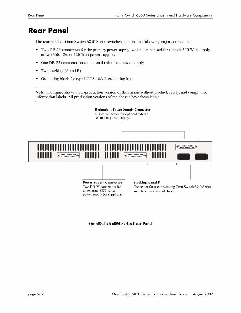
Rear Panel OmniSwitch 6850 Series Chassis and Hardware Components
Rear PanelThe rear panel of OmniSwitch 6850 Series switches contains the following major components:
• Two DB-25 connectors for the primary power supply, which can be used for a single 510 Watt supply or two 360, 126, or 120 Watt power supplies
• One DB-25 connector for an optional redundant power supply
• Two stacking (A and B)
• Grounding block for type LCD8-10A-L grounding lug
Note. The figure shows a pre-production version of the chassis without product, safety, and compliance information labels. All production versions of the chassis have these labels.
OmniSwitch 6850 Series Rear Panel
Redundant Power Supply ConnectorDB-25 connector for optional external redundant power supply.
Power Supply ConnectorsTwo DB-25 connectors for an external 6850 series power supply (or supplies).
Stacking A and BConnector for use in stacking OmniSwitch 6850 Seriesswitches into a virtual chassis.
page 2-56 OmniSwitch 6850 Series Hardware Users Guide August 2007
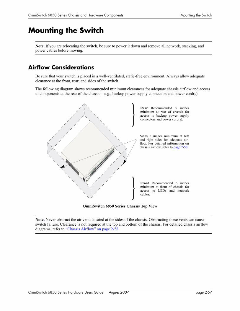
OmniSwitch 6850 Series Chassis and Hardware Components Mounting the Switch
Mounting the Switch
Note. If you are relocating the switch, be sure to power it down and remove all network, stacking, and power cables before moving.
Airflow ConsiderationsBe sure that your switch is placed in a well-ventilated, static-free environment. Always allow adequate clearance at the front, rear, and sides of the switch.
The following diagram shows recommended minimum clearances for adequate chassis airflow and access to components at the rear of the chassis—e.g., backup power supply connectors and power cord(s).
OmniSwitch 6850 Series Chassis Top View
Note. Never obstruct the air vents located at the sides of the chassis. Obstructing these vents can cause switch failure. Clearance is not required at the top and bottom of the chassis. For detailed chassis airflow diagrams, refer to “Chassis Airflow” on page 2-58.
OmniSwitch
6850-
48
USB
CLASS 1 L
ASER PR
ODUCT
OK
1
2
3
4
PRI
PWR
BPS
1
2
3
4
5
6
7
8
9
10
11
12
13
14
1
5
16
17
18
1
9
20
21
2
2
23
24
2
5
26
27
2
8
29
30
31
3
2
33
34
35
3
6
37
3
8
39
40
41
4
2
43
44
45
4
6
47
48
} Rear Recommended 5 inchesminimum at rear of chassis foraccess to backup power supplyconnectors and power cord(s).
Sides 2 inches minimum at leftand right sides for adequate air-flow. For detailed information onchassis airflow, refer to page 2-58.
Front Recommended 6 inchesminimum at front of chassis foraccess to LEDs and networkcables.}
OmniSwitch 6850 Series Hardware Users Guide August 2007 page 2-57
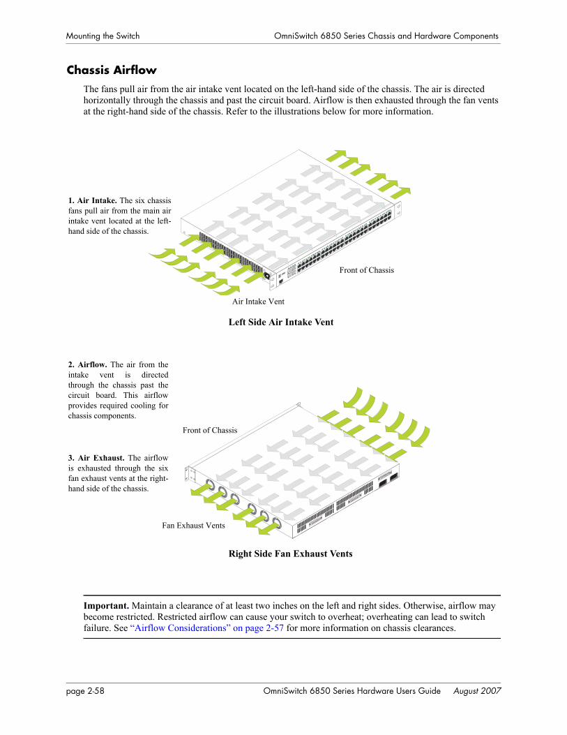
Mounting the Switch OmniSwitch 6850 Series Chassis and Hardware Components
Chassis AirflowThe fans pull air from the air intake vent located on the left-hand side of the chassis. The air is directed horizontally through the chassis and past the circuit board. Airflow is then exhausted through the fan vents at the right-hand side of the chassis. Refer to the illustrations below for more information.
Important. Maintain a clearance of at least two inches on the left and right sides. Otherwise, airflow may become restricted. Restricted airflow can cause your switch to overheat; overheating can lead to switch failure. See “Airflow Considerations” on page 2-57 for more information on chassis clearances.
45
47
46
48
Console
1. Air Intake. The six chassisfans pull air from the main airintake vent located at the left-hand side of the chassis.
2. Airflow. The air from theintake vent is directedthrough the chassis past thecircuit board. This airflowprovides required cooling forchassis components.
3. Air Exhaust. The airflowis exhausted through the sixfan exhaust vents at the right-hand side of the chassis.
Left Side Air Intake Vent
Right Side Fan Exhaust Vents
Air Intake Vent
Front of Chassis
Front of Chassis
Fan Exhaust Vents
page 2-58 OmniSwitch 6850 Series Hardware Users Guide August 2007

OmniSwitch 6850 Series Chassis and Hardware Components Mounting the Switch
Blank Cover PanelsBlank cover panels are provided with your switch and are used to cover empty backup power supply bays and 10 Gigabit uplink bays (all OmniSwitch 6850 Series switches, except for OmniSwitch 6850-24, OmniSwitch 6850-P24, OmniSwitch 6850-48, and OmniSwitch 6850-P48). These cover panels play an important role in chassis airflow and temperature management. They also protect the switch’s processor board and other sensitive internal switch components from physical damage by closing off the chassis.
When blank cover panels are missing, air does not take the direct route from the air intake vent, through the chassis, and then out through the fan exhaust vents (see page 2-58). Instead, a portion of the airflow is allowed to be drawn in through the rear of the chassis. As a result, normal airflow is disrupted and an extra task is placed on the fans to cool the chassis.
If your switch is not equipped with a backup power supply connection or 10 Gigabit uplink, and blank cover panels are not installed over empty bay locations, airflow is adversely affected. Since they regulate airflow and help protect internal chassis components, blank cover panels should remain installed over empty bays at all times.
OmniSwitch 6850 Series Hardware Users Guide August 2007 page 2-59
Mounting the Switch OmniSwitch 6850 Series Chassis and Hardware Components
Installation OptionsThe OmniSwitch 6850 Series switches can be installed in two ways:
• Tabletop installation
• Rack-mount installation
Installing the Switch on a Tabletop or BenchOmniSwitch 6850 Series switches can be installed freestanding as tabletop units. Place your switch on a stable, flat, and static-free surface.
Note. OmniSwitch 6850 Series switches must be placed “right side up.” Never attempt to operate a switch positioned on its side.
Tabletop Mounting Steps
To install the switch as a tabletop unit, follow the steps below:
1 Position the chassis on the table or bench where it is to be installed.
2 Be sure that adequate clearance has been provided for chassis airflow and access to the front, back, and sides of the switch. For recommended clearances, refer to page 2-57. Also, be sure that you have placed the chassis within the reach of all the required AC power sources.
3 If you are installing a single (i.e., stand-alone) switch, continue to “Setting Up a Stacked Configura-tion” on page 2-63 for additional setup procedures.
If you are placing multiple switches in a stacked configuration, carefully stack the remaining switches, one on top of the other. Up to eight switches may be stacked to form a single virtual chassis. Be sure to main-tain adequate clearance at the front, rear, left, and right side of all switches (see page 2-57). Also, be sure that you have placed all switches in the stack within reach of required AC power sources. Once the switches are stacked together, continue to “Cabling Stacked Configurations” on page 2-63 for additional setup procedures.
Note. Switches should be added one at a time in a stack.
Note. For comprehensive information on operating switches in a stacked configuration, refer to Chapter 4, “Managing OmniSwitch 6850 Series Stacks.”
page 2-60 OmniSwitch 6850 Series Hardware Users Guide August 2007
OmniSwitch 6850 Series Chassis and Hardware Components Mounting the Switch
Rack-Mounting the SwitchRefer to the important guidelines below before installing the OmniSwitch 6850 Series chassis on a rack.
• It is recommended that two people install the switch on the rack—one person to hold the chassis and position it on the rack, and a second person to secure the chassis to the rack using attachment screws (not supplied).
• Alcatel-Lucent provides two rack-mount flanges with each OmniSwitch 6850 Series switch. These flanges support standard 19-inch rack-mount installations. These flanges must be attached to the chas-sis before the switch can be rack mounted.
Note. If you are installing the switch in a 23-inch-wide rack, Alcatel-Lucent offers optional 23-inch rack-mounting hardware. For more information, contact your Alcatel-Lucent representative.
• Alcatel-Lucent does not provide rack-mount screws. Use the screws supplied by the rack vendor.
• To prevent a rack from becoming top heavy, it is recommended that you install heavier equipment at the bottom of the rack, whenever possible.
• If you are installing the switch on a relay rack, be sure to install and secure the rack per the rack manu-facturer’s specifications.
• Review page 2-57 for important chassis airflow and access recommendations before installing.
Rack Mounting Steps
To rack-mount the switch, follow the steps below:
1 Align the holes in the provided rack-mount flanges with the four threaded holes in the OmniSwitch 6850 Series chassis. These threaded holes are located in the left and right sides of the chassis, near the front panel.
2 Attach the flanges to the chassis using the provided Phillips-head screws. Be sure to tighten each of the screws firmly using a Phillips screwdriver.
Attaching a Rack-Mount Flange
45
46
Console
OmniSwitch 6850 Series Hardware Users Guide August 2007 page 2-61
Mounting the Switch OmniSwitch 6850 Series Chassis and Hardware Components
3 After the rack-mount flanges are secured to the chassis, mark the holes on the rack where the switch is to be installed.
4 Lift and position the switch until the rack-mount flanges are flush with the rack post.
5 Align the holes in the flanges with the rack holes that were marked in step 3.
6 Once the holes are aligned, insert a rack mount screw (not provided) through the bottom hole of each flange. Tighten both screws until they are secure.
Attaching the Switch to the Rack
Note. Be sure to install the screws in the bottom hole of each flange, as shown, before proceeding.
7 Once the screws at the bottom of each flange are secure, install the remaining two rack mount screws. Be sure that all screws are securely tightened.
Note. If you are installing multiple switches in a rack to form a stacked configuration, refer to “Setting Up a Stacked Configuration” on page 2-63.
Installing and Removing Combo Port SFPsOmniSwitch 6850 Series switches offer four Gigabit Ethernet combo, located on the front panel (see page 2-23). These combo support hot-swappable fiber Small Form-Factor Pluggables (SFPs). For instructions on installing and removing combo connector SFPs, refer to the instruction card provided with the SFP product.
Note. Combo port preferences are user-configurable via the system software. Refer to the “Configuring Ethernet” in the OmniSwitch 6850 Series Network Configuration Guide for complete details.
page 2-62 OmniSwitch 6850 Series Hardware Users Guide August 2007
OmniSwitch 6850 Series Chassis and Hardware Components Setting Up a Stacked Configuration
Setting Up a Stacked Configuration
Rack Mounting Stacked ConfigurationsTo rack mount a stacked configuration, install all switches that are to be included in the stacked configura-tion as described on pages 2-61 through 2-62. Up to eight switches may be stacked to form a single virtual chassis.
Note. You cannot mix OS6800 and OS6850 switches in a stack.
Note. When rack mounting multiple switches in a stacked configuration, be sure to place all switches in vertically-adjacent rack positions. This will ensure that all required stacking cables will have adequate length for the installation.
Cabling Stacked ConfigurationsIn order to connect stacked switches into a virtual chassis, all modules in the stack must be connected via stacking cables (provided).
Redundant Stacking Cable ConnectionsIn addition to the stacking cables installed between adjacent switch, the top-most switch and bottom-most switch in the stack must be connected using a redundant stacking cable. Refer to Chapter 4, “Managing OmniSwitch 6850 Series Stacks” for more information on the redundant stacking cable connection.
Supported Cabling PatternsEach switch provides two stacking: stacking port A and stacking port B. Cables can be connected in any pattern. In other words, the cable connected to stacking port A of one switch can be connected to either stacking port A or stacking port B of the adjacent switch. However, it is strongly recommended that the cabling pattern remains consistent across the stack. For a cabling diagram and additional information on cabling the stack, refer to Chapter 4, “Managing OmniSwitch 6850 Series Stacks.”
Cabling Steps
1 Before inserting a stacking cable into one of the stacking, be sure to orient the stacking cable connec-tor properly. The wide portion of the connector must be facing up. Refer to the diagram below for more information.
End View of Stacking Cable Connector
Connector TopWhen orienting the stacking cable connector, be sure that the wider portion of the connector is facing up as shown. Otherwise, the stacking cable will not fit properly in the chassis’ stacking port.
OmniSwitch 6850 Series Hardware Users Guide August 2007 page 2-63
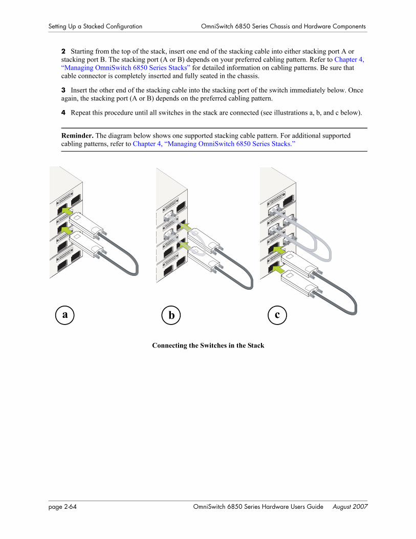
Setting Up a Stacked Configuration OmniSwitch 6850 Series Chassis and Hardware Components
2 Starting from the top of the stack, insert one end of the stacking cable into either stacking port A or stacking port B. The stacking port (A or B) depends on your preferred cabling pattern. Refer to Chapter 4, “Managing OmniSwitch 6850 Series Stacks” for detailed information on cabling patterns. Be sure that cable connector is completely inserted and fully seated in the chassis.
3 Insert the other end of the stacking cable into the stacking port of the switch immediately below. Once again, the stacking port (A or B) depends on the preferred cabling pattern.
4 Repeat this procedure until all switches in the stack are connected (see illustrations a, b, and c below).
Reminder. The diagram below shows one supported stacking cable pattern. For additional supported cabling patterns, refer to Chapter 4, “Managing OmniSwitch 6850 Series Stacks.”
Connecting the Switches in the Stack
a b c
page 2-64 OmniSwitch 6850 Series Hardware Users Guide August 2007
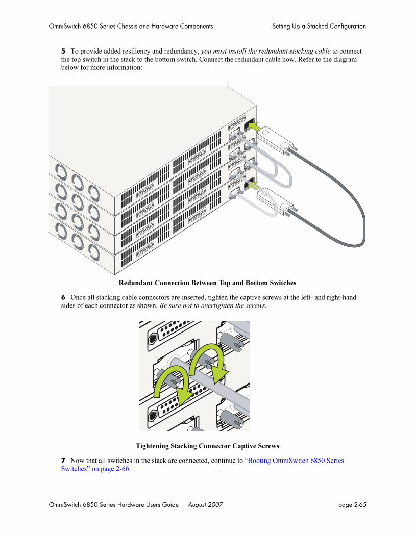
OmniSwitch 6850 Series Chassis and Hardware Components Setting Up a Stacked Configuration
5 To provide added resiliency and redundancy, you must install the redundant stacking cable to connect the top switch in the stack to the bottom switch. Connect the redundant cable now. Refer to the diagram below for more information:
Redundant Connection Between Top and Bottom Switches
6 Once all stacking cable connectors are inserted, tighten the captive screws at the left- and right-hand sides of each connector as shown. Be sure not to overtighten the screws.
Tightening Stacking Connector Captive Screws
7 Now that all switches in the stack are connected, continue to “Booting OmniSwitch 6850 Series Switches” on page 2-66.
OmniSwitch 6850 Series Hardware Users Guide August 2007 page 2-65
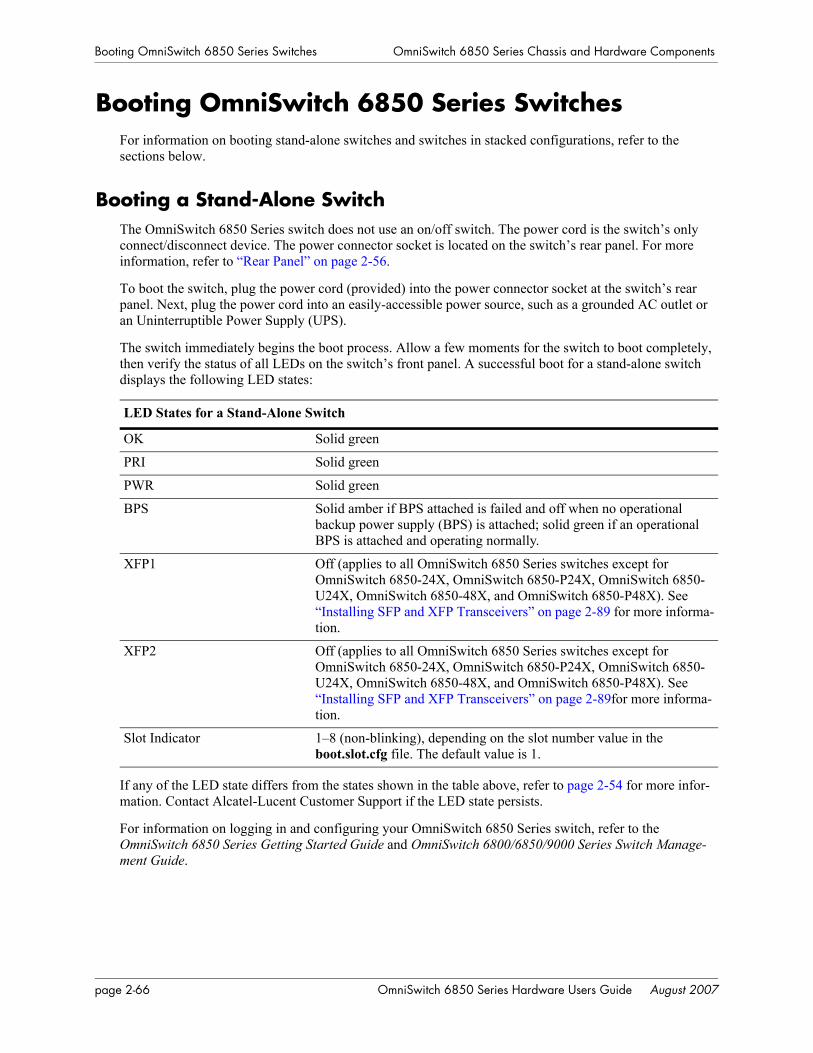
Booting OmniSwitch 6850 Series Switches OmniSwitch 6850 Series Chassis and Hardware Components
Booting OmniSwitch 6850 Series SwitchesFor information on booting stand-alone switches and switches in stacked configurations, refer to the sections below.
Booting a Stand-Alone SwitchThe OmniSwitch 6850 Series switch does not use an on/off switch. The power cord is the switch’s only connect/disconnect device. The power connector socket is located on the switch’s rear panel. For more information, refer to “Rear Panel” on page 2-56.
To boot the switch, plug the power cord (provided) into the power connector socket at the switch’s rear panel. Next, plug the power cord into an easily-accessible power source, such as a grounded AC outlet or an Uninterruptible Power Supply (UPS).
The switch immediately begins the boot process. Allow a few moments for the switch to boot completely, then verify the status of all LEDs on the switch’s front panel. A successful boot for a stand-alone switch displays the following LED states:
If any of the LED state differs from the states shown in the table above, refer to page 2-54 for more infor-mation. Contact Alcatel-Lucent Customer Support if the LED state persists.
For information on logging in and configuring your OmniSwitch 6850 Series switch, refer to the OmniSwitch 6850 Series Getting Started Guide and OmniSwitch 6800/6850/9000 Series Switch Manage-ment Guide.
LED States for a Stand-Alone Switch
OK Solid green
PRI Solid green
PWR Solid green
BPS Solid amber if BPS attached is failed and off when no operational backup power supply (BPS) is attached; solid green if an operational BPS is attached and operating normally.
XFP1 Off (applies to all OmniSwitch 6850 Series switches except for OmniSwitch 6850-24X, OmniSwitch 6850-P24X, OmniSwitch 6850-U24X, OmniSwitch 6850-48X, and OmniSwitch 6850-P48X). See “Installing SFP and XFP Transceivers” on page 2-89 for more informa-tion.
XFP2 Off (applies to all OmniSwitch 6850 Series switches except for OmniSwitch 6850-24X, OmniSwitch 6850-P24X, OmniSwitch 6850-U24X, OmniSwitch 6850-48X, and OmniSwitch 6850-P48X). See “Installing SFP and XFP Transceivers” on page 2-89for more informa-tion.
Slot Indicator 1–8 (non-blinking), depending on the slot number value in the boot.slot.cfg file. The default value is 1.
page 2-66 OmniSwitch 6850 Series Hardware Users Guide August 2007
OmniSwitch 6850 Series Chassis and Hardware Components Booting OmniSwitch 6850 Series Switches
Booting Stacked ConfigurationsOnce the switches have been connected to a virtual chassis, the next step is to manually power on the stack. The OmniSwitch 6850 Series switch does not use an on/off switch. The power cord is the switch’s only connect/disconnect device. The power connector socket is located on the switch’s rear panel. For more information, refer to “Rear Panel” on page 2-56.
To boot the stack, plug the power cord (provided) into the power connector socket at the rear panel of each switch in the stack. Next, plug all power cords, in rapid succession, into easily-accessible power sources, such as grounded AC outlets or an Uninterruptible Power Supply (UPS).
Note. Be sure to power on all switches in the stack in rapid succession; otherwise, switches may be assigned unintended stack management roles. Refer to Chapter 4, “Managing OmniSwitch 6850 Series Stacks” for detailed information.
The stack immediately begins the boot process. Allow a few moments for all elements in the stack to boot completely, then verify the status of all LEDs on the switch’s front panel. A successful boot for a stand-alone switch displays the following LED states.
If any of the LED state differs from the states shown in the table above, refer to page 2-54 for more infor-mation. Contact Alcatel-Lucent Customer Support if the LED state persists. For information on logging in and configuring your OmniSwitch 6850 Series stack, refer to the OmniSwitch 6850 Series Getting Started Guide and OmniSwitch 6800/6850/9000 Series Switch Management Guide.
LED States for a Stacked Configuration
OK Solid green for all switches.
PRI Solid green for the primary management module; solid amber for the secondary management module; off for switches operating in idle roles. Detailed information for primary, secondary, and idle roles is provided in Chapter 4, “Managing OmniSwitch 6850 Series Stacks.”
PWR Solid green for all switches.
BPS Solid amber if BPS attached is failed and off when no operational backup power supply (BPS) is attached; solid green if an operational BPS is attached and operating normally.
XFP1 Off (applies to all OmniSwitch 6850 Series switches except for OmniSwitch 6850-24X, OmniSwitch 6850-P24X, OmniSwitch 6850-U24X, OmniSwitch 6850-48X, and OmniSwitch 6850-P48X). See “Installing SFP and XFP Transceivers” on page 2-89 for more informa-tion.
XFP2 Off (applies to all OmniSwitch 6850 Series switches except for the OmniSwitch 6850-24X, OmniSwitch 6850-P24X, OmniSwitch 6850-U24X, OmniSwitch 6850-48X, and OmniSwitch 6850-P48X). See “Installing SFP and XFP Transceivers” on page 2-89 for more informa-tion.
Slot Indicator 1–8 (non-blinking), depending on the slot number assignment for each corresponding switch. See Chapter 4, “Managing OmniSwitch 6850 Series Stacks” for detailed information.
OmniSwitch 6850 Series Hardware Users Guide August 2007 page 2-67
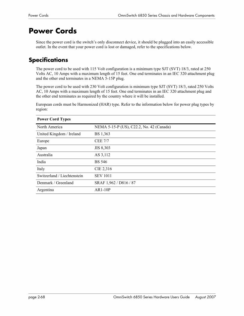
Power Cords OmniSwitch 6850 Series Chassis and Hardware Components
Power CordsSince the power cord is the switch’s only disconnect device, it should be plugged into an easily accessible outlet. In the event that your power cord is lost or damaged, refer to the specifications below.
SpecificationsThe power cord to be used with 115 Volt configuration is a minimum type SJT (SVT) 18/3, rated at 250 Volts AC, 10 Amps with a maximum length of 15 feet. One end terminates in an IEC 320 attachment plug and the other end terminates in a NEMA 5-15P plug.
The power cord to be used with 230 Volt configuration is minimum type SJT (SVT) 18/3, rated 250 Volts AC, 10 Amps with a maximum length of 15 feet. One end terminates in an IEC 320 attachment plug and the other end terminates as required by the country where it will be installed.
European cords must be Harmonized (HAR) type. Refer to the information below for power plug types by region:
Power Cord Types
North America NEMA 5-15-P (US), C22.2, No. 42 (Canada)
United Kingdom / Ireland BS 1,363
Europe CEE 7/7
Japan JIS 8,303
Australia AS 3,112
India BS 546
Italy CIE 2,316
Switzerland / Liechtenstein SEV 1011
Denmark / Greenland SRAF 1,962 / D816 / 87
Argentina AR1-10P
page 2-68 OmniSwitch 6850 Series Hardware Users Guide August 2007
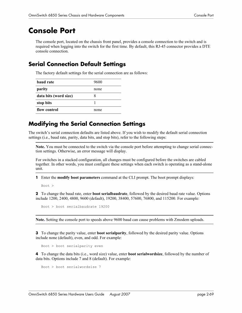
OmniSwitch 6850 Series Chassis and Hardware Components Console Port
Console PortThe console port, located on the chassis front panel, provides a console connection to the switch and is required when logging into the switch for the first time. By default, this RJ-45 connector provides a DTE console connection.
Serial Connection Default SettingsThe factory default settings for the serial connection are as follows:
Modifying the Serial Connection SettingsThe switch’s serial connection defaults are listed above. If you wish to modify the default serial connection settings (i.e., baud rate, parity, data bits, and stop bits), refer to the following steps:
Note. You must be connected to the switch via the console port before attempting to change serial connec-tion settings. Otherwise, an error message will display.
For switches in a stacked configuration, all changes must be configured before the switches are cabled together. In other words, you must configure these settings when each switch is operating as a stand-alone unit.
1 Enter the modify boot parameters command at the CLI prompt. The boot prompt displays:
Boot >
2 To change the baud rate, enter boot serialbaudrate, followed by the desired baud rate value. Options include 1200, 2400, 4800, 9600 (default), 19200, 38400, 57600, 76800, and 115200. For example:
Boot > boot serialbaudrate 19200
Note. Setting the console port to speeds above 9600 baud can cause problems with Zmodem uploads.
3 To change the parity value, enter boot serialparity, followed by the desired parity value. Options include none (default), even, and odd. For example:
Boot > boot serialparity even
4 To change the data bits (i.e., word size) value, enter boot serialwordsize, followed by the number of data bits. Options include 7 and 8 (default). For example:
Boot > boot serialwordsize 7
baud rate 9600
parity none
data bits (word size) 8
stop bits 1
flow control none
OmniSwitch 6850 Series Hardware Users Guide August 2007 page 2-69

Console Port OmniSwitch 6850 Series Chassis and Hardware Components
5 To change the stop bits value, enter boot serialstopbits, followed by the number of stop bits. Options include 1 (default) and 2. For example:
Boot > boot serialstopbits 2
6 Verify your current changes by entering show at the boot prompt:
Boot > showEdit buffer contents:Serial (console) baud : 19200Serial (console) parity : evenSerial (console) stopbits : 2Serial (console) wordsize : 7
(additional table output not shown)
7 You can save your changes to the boot.params file by entering commit file at the boot prompt:
Boot > commit file
When the commit file command is used, changes will not be enabled until after the next switch reboot.
8 You can also save your changes in real time to the switch’s running memory by entering commit system at the boot prompt:
Boot > commit system
Caution. There are two important things to consider when using the commit system command to save serial connection changes:
• Output to the terminal may become illegible due to incompatible serial connection settings between the switch and the terminal emulation software.
• If you use the commit system command only, changes will not be saved to the switch’s boot.params file and will be lost if the switch is rebooted. To save changes to the boot.params file, refer to step 7.
9 Return to the CLI prompt by entering exit at the boot prompt.
page 2-70 OmniSwitch 6850 Series Hardware Users Guide August 2007
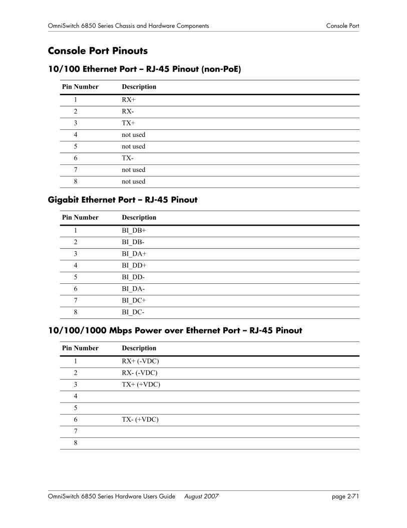
OmniSwitch 6850 Series Chassis and Hardware Components Console Port
Console Port Pinouts
10/100 Ethernet Port – RJ-45 Pinout (non-PoE)
Gigabit Ethernet Port – RJ-45 Pinout
10/100/1000 Mbps Power over Ethernet Port – RJ-45 Pinout
Pin Number Description
1 RX+
2 RX-
3 TX+
4 not used
5 not used
6 TX-
7 not used
8 not used
Pin Number Description
1 BI_DB+
2 BI_DB-
3 BI_DA+
4 BI_DD+
5 BI_DD-
6 BI_DA-
7 BI_DC+
8 BI_DC-
Pin Number Description
1 RX+ (-VDC)
2 RX- (-VDC)
3 TX+ (+VDC)
4
5
6 TX- (+VDC)
7
8
OmniSwitch 6850 Series Hardware Users Guide August 2007 page 2-71

Console Port OmniSwitch 6850 Series Chassis and Hardware Components
RJ-45 Console Port – Connector Pinout
Pin Number Signals as DTE Console Port
1 NC
2 NC
3 RXD
4 Ground
5 Ground
6 TXD
7 NC
8 NC
page 2-72 OmniSwitch 6850 Series Hardware Users Guide August 2007

OmniSwitch 6850 Series Chassis and Hardware Components OmniSwitch 6850 Series Power Supplies
OmniSwitch 6850 Series Power SuppliesOmniSwitch 6850 Series switches support the following power supplies:
• PS-510W-AC power supply (see “PS-510W-AC Power Supply” on page 2-76)
• PS-360W-AC power supply (see “PS-360W-AC Power Supply” on page 2-77)
• PS-126W-AC power supply (see “PS-126W-AC Power Supply” on page 2-78)
• PS-120W-DC power supply (see “PS-120W-DC Power Supply” on page 2-79)
Approximately 120W is dedicated to system power needed for the chassis and the rest of the power is utilized for Power over Ethernet (PoE). The power supplies connect to the rear of the unit. There is a power shelf provided with the unit that slides into the rear of the chassis and is used to hold the power supplies. It can hold either one 510W power supply or two 360W power supplies or in case of non-PoE product switches two 120W or two 126W power supplies. See the table below for valid configurations.
Model Primary Power Supply Backup Power Supply Valid
Configuration?
OS6850-P48L, OS6850-P48, OS6850-P48X, OS6850-P24L, OS6850-P24, OS6850-P24X
510W 510W Valid
OS6850-P48L, OS6850-P48, OS6850-P48X, OS6850-P24L, OS6850-P24, OS6850-P24X
360W 360W Valid
OS6850-P48L, OS6850-P48, OS6850-P48X, OS6850-P24L, OS6850-P24, OS6850-P24X
360W 510W Not Valid
OS6850-P48L, OS6850-P48, OS6850-P48X, OS6850-P24L, OS6850-P24, OS6850-P24X
510W 360W Not Valid
OS6850-P48L, OS6850-P48, OS6850-P48X, OS6850-P24L, OS6850-P24, OS6850-P24X
510W 126W Not Valid
OS6850-P48L, OS6850-P48, OS6850-P48X, OS6850-P24L, OS6850-P24, OS6850-P24X
510W 120W Not Valid
OS6850-P48L, OS6850-P48, OS6850-P48X, OS6850-P24L, OS6850-P24, OS6850-P24X
360W 126W Not Valid
OS6850-P48L, OS6850-P48, OS6850-P48X, OS6850-P24L, OS6850-P24, OS6850-P24X
360W 120W Not Valid
OS6850-P48L, OS6850-P48, OS6850-P48X, OS6850-P24L, OS6850-P24, OS6850-P24X
126W (AC) None Not Valid
OmniSwitch 6850 Series Hardware Users Guide August 2007 page 2-73

OmniSwitch 6850 Series Power Supplies OmniSwitch 6850 Series Chassis and Hardware Components
The power supplies can also be connected using a cable, in case there is a need for a less deep chassis. In this case, the same power shelf can be mounted in the rack using the mounting ears (removable in case the power supply needs to be plugged into the rear of the chassis).
Note. PoE units support either 510W or 360W power supplies. If unlike power supplies are mixed or if an unsupported power supply (such as a 120W power supply) is used, a console message and a trap are gener-ated.
OS6850-P48L, OS6850-P48, OS6850-P48X, OS6850-P24L, OS6850-P24, OS6850-P24X
120W (DC) None Not Valid
OS6850-48, OS6850-48X, OS6850-24, OS6850-24X, OS6850-U24X, OS6850-24L, OS6850-48L
126W (AC) 126W (AC) Valid
OS6850-48, OS6850-48X, OS6850-24, OS6850-24X, OS6850-U24X, OS6850-24L, OS6850-48L
120W (DC) 120W (DC) Valid
OS6850-48, OS6850-48X, OS6850-24, OS6850-24X, OS6850-U24X, OS6850-24L, OS6850-48L
126W (AC) 120W (DC) Valid
OS6850-48, OS6850-48X, OS6850-24, OS6850-24X, OS6850-U24X, OS6850-24L, OS6850-48L
120W (DC) 126W (AC) Valid
OS6850-48, OS6850-48X, OS6850-24, OS6850-24X, OS6850-U24X, OS6850-24L, OS6850-48L
126W (AC) 510W Not Valid
OS6850-48, OS6850-48X, OS6850-24, OS6850-24X, OS6850-U24X, OS6850-24L, OS6850-48L
120W (DC) 360W Not Valid
OS6850-48, OS6850-48X, OS6850-24, OS6850-24X, OS6850-U24X, OS6850-24L, OS6850-48L
510W None Not Valid
OS6850-48, OS6850-48X, OS6850-24, OS6850-24X, OS6850-U24X, OS6850-24L, OS6850-48L
360W None Not Valid
Model Primary Power Supply Backup Power Supply Valid
Configuration?
page 2-74 OmniSwitch 6850 Series Hardware Users Guide August 2007
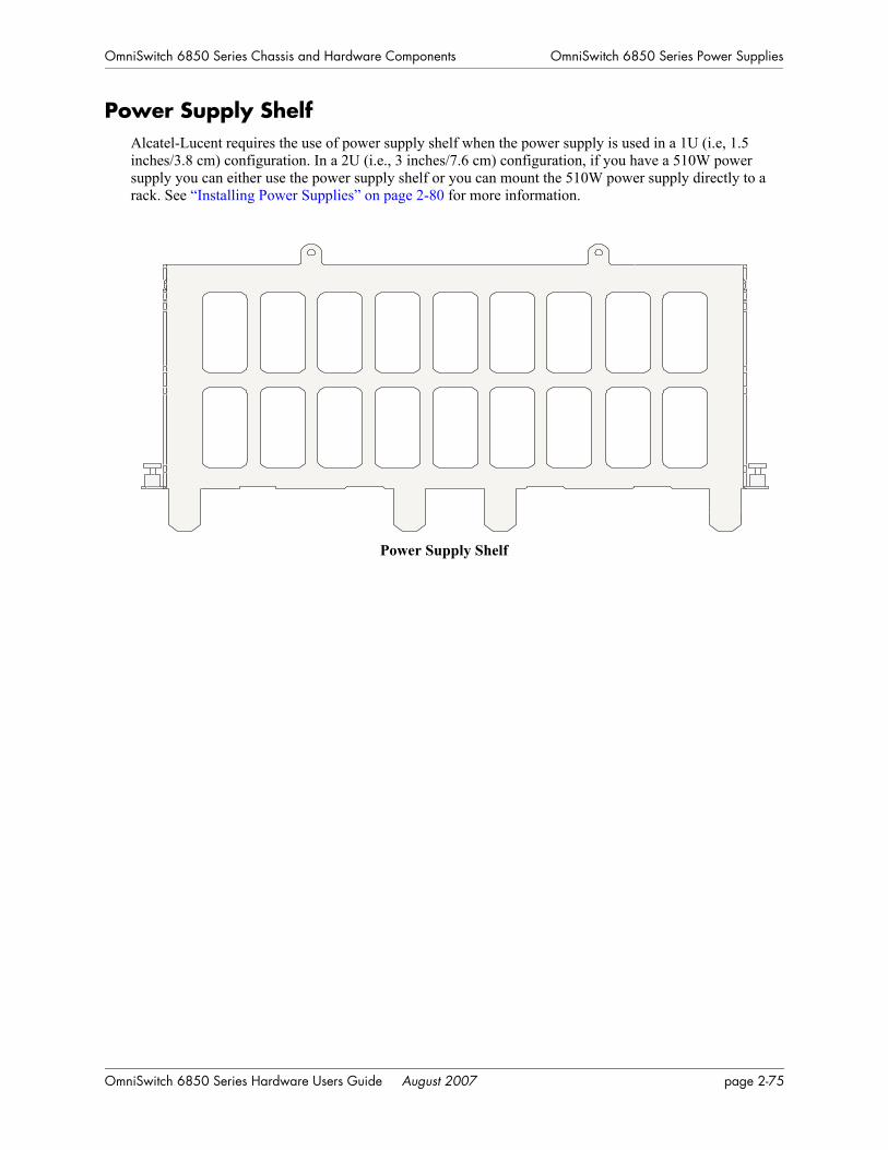
OmniSwitch 6850 Series Chassis and Hardware Components OmniSwitch 6850 Series Power Supplies
Power Supply ShelfAlcatel-Lucent requires the use of power supply shelf when the power supply is used in a 1U (i.e, 1.5 inches/3.8 cm) configuration. In a 2U (i.e., 3 inches/7.6 cm) configuration, if you have a 510W power supply you can either use the power supply shelf or you can mount the 510W power supply directly to a rack. See “Installing Power Supplies” on page 2-80 for more information.
Power Supply Shelf
OmniSwitch 6850 Series Hardware Users Guide August 2007 page 2-75
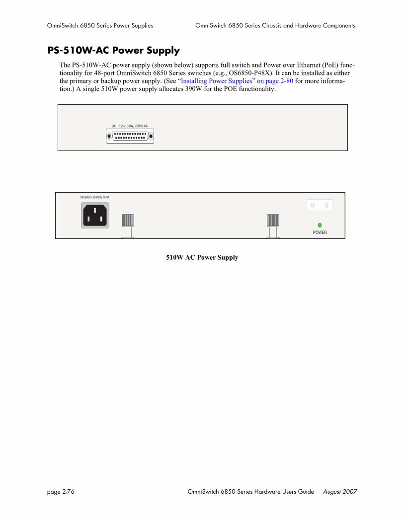
OmniSwitch 6850 Series Power Supplies OmniSwitch 6850 Series Chassis and Hardware Components
PS-510W-AC Power SupplyThe PS-510W-AC power supply (shown below) supports full switch and Power over Ethernet (PoE) func-tionality for 48-port OmniSwitch 6850 Series switches (e.g., OS6850-P48X). It can be installed as either the primary or backup power supply. (See “Installing Power Supplies” on page 2-80 for more informa-tion.) A single 510W power supply allocates 390W for the POE functionality.
510W AC Power Supply
page 2-76 OmniSwitch 6850 Series Hardware Users Guide August 2007

OmniSwitch 6850 Series Chassis and Hardware Components OmniSwitch 6850 Series Power Supplies
PS-360W-AC Power SupplyThe PS-360W-AC power supply (shown below) supplies full switch and Power over Ethernet (PoE) func-tionality for 24-port OmniSwitch 6850 Series switches (e.g., OS6850-P24X). In addition, two 360W power supplies support full switch and PoE functionality for 48-port OmniSwitch 6850 Series switches (e.g., OS6850-P48X) while a single 360W power supply supplies switch but only partial support for PoE on 48-port switches A single 360W allocates 240W for the POE functionality.
360W AC Power Supply
In addition, the 360W power supply can be installed as a primary or backup power supply. (See “Install-ing Power Supplies” on page 2-80 for more information.)
OmniSwitch 6850 Series Hardware Users Guide August 2007 page 2-77

OmniSwitch 6850 Series Power Supplies OmniSwitch 6850 Series Chassis and Hardware Components
PS-126W-AC Power SupplyThe PS-126W-AC power supply supplies switch functionality for non-PoE OmniSwitch 6850 Series switches (e.g., OS6850-24).
In addition, the 126W power supply can be installed as one of the two primary supplies or as a backup power supply.(See “Installing Power Supplies” on page 2-80 for more information.)
126W AC Power Supply
Note. The PS-126W-AC power supply has the same physical dimensions and interfaces as the PS-360W-AC power supply.
page 2-78 OmniSwitch 6850 Series Hardware Users Guide August 2007

OmniSwitch 6850 Series Chassis and Hardware Components OmniSwitch 6850 Series Power Supplies
PS-120W-DC Power SupplyThe PS-120W-DC power supply (shown below) supplies switch functionality for non-PoE OmniSwitch 6850 Series switches (e.g., OS6850-24).
In addition, the 120W power supply can be installed as one of the two primary supplies or as a backup power supply. (See “Installing Power Supplies” on page 2-80 for more information.)
120W DC Power Supply
Note. The PS-120W-DC power supply has the same physical dimensions and interfaces as the PS-360W-AC power supply.
OmniSwitch 6850 Series Hardware Users Guide August 2007 page 2-79
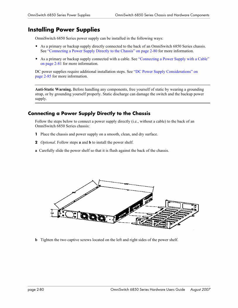
OmniSwitch 6850 Series Power Supplies OmniSwitch 6850 Series Chassis and Hardware Components
Installing Power SuppliesOmniSwitch 6850 Series power supply can be installed in the following ways:
• As a primary or backup supply directly connected to the back of an OmniSwitch 6850 Series chassis. See “Connecting a Power Supply Directly to the Chassis” on page 2-80 for more information.
• As a primary or backup supply connected with a cable. See “Connecting a Power Supply with a Cable” on page 2-81 for more information.
DC power supplies require additional installation steps. See “DC Power Supply Considerations” on page 2-85 for more information.
Anti-Static Warning. Before handling any components, free yourself of static by wearing a grounding strap, or by grounding yourself properly. Static discharge can damage the switch and the backup power supply.
Connecting a Power Supply Directly to the ChassisFollow the steps below to connect a power supply directly (i.e., without a cable) to the back of an OmniSwitch 6850 Series chassis:
1 Place the chassis and power supply on a smooth, clean, and dry surface.
2 Optional. Follow steps a and b to install the power shelf.
a Carefully slide the power shelf so that it is flush against the back of the chassis.
b Tighten the two captive screws located on the left and right sides of the power shelf.
page 2-80 OmniSwitch 6850 Series Hardware Users Guide August 2007
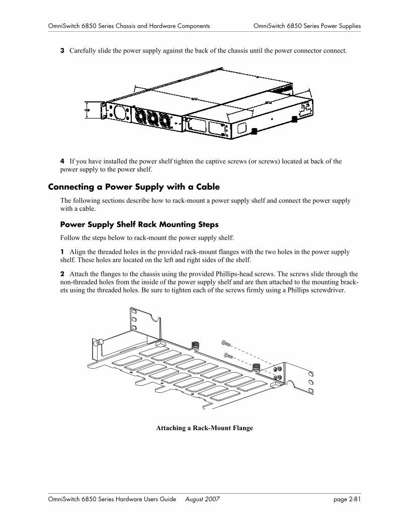
OmniSwitch 6850 Series Chassis and Hardware Components OmniSwitch 6850 Series Power Supplies
3 Carefully slide the power supply against the back of the chassis until the power connector connect.
4 If you have installed the power shelf tighten the captive screws (or screws) located at back of the power supply to the power shelf.
Connecting a Power Supply with a CableThe following sections describe how to rack-mount a power supply shelf and connect the power supply with a cable.
Power Supply Shelf Rack Mounting Steps
Follow the steps below to rack-mount the power supply shelf:
1 Align the threaded holes in the provided rack-mount flanges with the two holes in the power supply shelf. These holes are located on the left and right sides of the shelf.
2 Attach the flanges to the chassis using the provided Phillips-head screws. The screws slide through the non-threaded holes from the inside of the power supply shelf and are then attached to the mounting brack-ets using the threaded holes. Be sure to tighten each of the screws firmly using a Phillips screwdriver.
Attaching a Rack-Mount Flange
OmniSwitch 6850 Series Hardware Users Guide August 2007 page 2-81

OmniSwitch 6850 Series Power Supplies OmniSwitch 6850 Series Chassis and Hardware Components
3 Carefully slide the power supply on to the power shelf and secure the power supply to the shelf using the captive screws.
Attaching a Power Supply to the Power Shelf
Note. A single 510W power supply or up to two of any other power supply types can be attached to a power supply shelf.
4 After the rack-mount flanges and the power supply are secured to the shelf, mark the holes on the rack where the shelf is to be installed.
5 Lift and position the shelf until the rack-mount flanges are flush with the rack post.
6 Align the holes in the flanges with the rack holes that were marked earlier.
7 Once the holes are aligned, insert a rack mount screw (not provided) through the bottom hole of each flange. Tighten both screws until they are secure.
Attaching the Power Shelf to the Rack
Note. Be sure to install the screws in the bottom hole of each flange, as shown, before proceeding.
Tighten these screws to secure the power supply.
page 2-82 OmniSwitch 6850 Series Hardware Users Guide August 2007

OmniSwitch 6850 Series Chassis and Hardware Components OmniSwitch 6850 Series Power Supplies
8 Once the screws at the bottom of each flange are secure, install the remaining two rack mount screws. Be sure that all screws are securely tightened.
Connecting the Power Supply Cable
Follow the steps below to connect a power supply with a cable:
1 Be sure the switch and power shelf are securely fastened to the rack.
2 Connect the proper end of the supplied power supply cable to the appropriately labeled primary or backup connector on the switch and tighten securely.
3 Connect the other end of the power supply cable to the power supply and securely tighten.
4 Connect the power cord to the power supply.
Note. The diagrams below show examples of mounting the switch and power supplies in both a 2U and 3U scenario. Depending on the switch model, power supplies, and rack mounting options the actual mounting options will vary.
OmniSwitch 6850 Series Hardware Users Guide August 2007 page 2-83
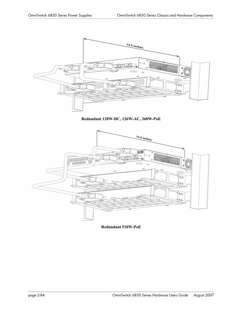
OmniSwitch 6850 Series Power Supplies OmniSwitch 6850 Series Chassis and Hardware Components
Redundant 120W-DC, 126W-AC, 360W-PoE
Redundant 510W-PoE
13.5 inches
13.5 inches
page 2-84 OmniSwitch 6850 Series Hardware Users Guide August 2007

OmniSwitch 6850 Series Chassis and Hardware Components OmniSwitch 6850 Series Power Supplies
You can also attach the power supplies to the back of an OmniSwitch 6850 Series chassis directly as well as using cables at the same time, as shown in the diagram below.
Redundant 510W-PoE
DC Power Supply ConsiderationsIn addition to the installation steps described in “Connecting a Power Supply Directly to the Chassis” on page 2-80 and “Connecting a Power Supply with a Cable” on page 2-81 DC power supplies (e.g., the PS-120W-DC) have the following additional considerations:
• Connect to a -48V or -60V reliably grounded DC SELV source.
• Use common DC return connections for the DC power supplies. The DC return terminal conductor should be connected to the equipment frame.
• The Branch Circuit Overcurrent Protection must be rated a Maximum of 15A.
• Use 12AWG solid conductors only.
• A readily accessible disconnect device that is suitably approved and rated shall be incorporated in the field wiring.
Twisted pair wire (red and black) for a DC power supply
Note. Refer to the wiring diagram for information on connecting the DC power supply to a DC power source.
17.6 inches
MIN 1 TURN PER 1.5
HALF TURN PER .75
Black
Red
OmniSwitch 6850 Series Hardware Users Guide August 2007 page 2-85

OmniSwitch 6850 Series Power Supplies OmniSwitch 6850 Series Chassis and Hardware Components
Viewing the Power Supply StatusThe switch constantly monitors the power supply operation. If either the primary or backup power source (optional) unexpectedly shuts down, the switch sends out a notification to the user. In addition, the power LED on the chassis front panel display solid amber.
Note. For detailed OmniSwitch 6850 Series LED information, refer to “Status LEDs” on page 2-54.
To check the number of power supplies currently operating, and the status of each power supply, use the show power command. For example:
-> show power
Power Supplies in chassis 1PS Operational Status---------+-------------------PS-1 UPPS-2 NOT PRESENT
The primary (i.e., factory-installed) power supply is listed as PS-1 in the show power command output. The backup power supply is listed as PS-2. In the example above, there is no backup power supply installed.
page 2-86 OmniSwitch 6850 Series Hardware Users Guide August 2007
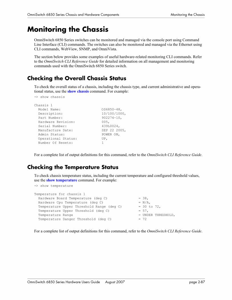
OmniSwitch 6850 Series Chassis and Hardware Components Monitoring the Chassis
Monitoring the ChassisOmniSwitch 6850 Series switches can be monitored and managed via the console port using Command Line Interface (CLI) commands. The switches can also be monitored and managed via the Ethernet using CLI commands, WebView, SNMP, and OmniVista.
The section below provides some examples of useful hardware-related monitoring CLI commands. Refer to the OmniSwitch CLI Reference Guide for detailed information on all management and monitoring commands used with the OmniSwitch 6850 Series switch.
Checking the Overall Chassis StatusTo check the overall status of a chassis, including the chassis type, and current administrative and opera-tional status, use the show chassis command. For example:-> show chassis
Chassis 1 Model Name: OS6850-48, Description: 10/100/1000, Part Number: 902274-10, Hardware Revision: 005, Serial Number: 439L0024, Manufacture Date: SEP 22 2005, Admin Status: POWER ON, Operational Status: UP, Number Of Resets: 1
For a complete list of output definitions for this command, refer to the OmniSwitch CLI Reference Guide.
Checking the Temperature StatusTo check chassis temperature status, including the current temperature and configured threshold values, use the show temperature command. For example:-> show temperature
Temperature for chassis 1 Hardware Board Temperature (deg C) = 38, Hardware Cpu Temperature (deg C) = N/A, Temperature Upper Threshold Range (deg C) = 30 to 72, Temperature Upper Threshold (deg C) = 57, Temperature Range = UNDER THRESHOLD, Temperature Danger Threshold (deg C) = 72
For a complete list of output definitions for this command, refer to the OmniSwitch CLI Reference Guide.
OmniSwitch 6850 Series Hardware Users Guide August 2007 page 2-87
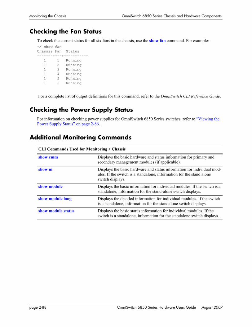
Monitoring the Chassis OmniSwitch 6850 Series Chassis and Hardware Components
Checking the Fan StatusTo check the current status for all six fans in the chassis, use the show fan command. For example:-> show fanChassis Fan Status-------+---+----------- 1 1 Running 1 2 Running 1 3 Running 1 4 Running 1 5 Running 1 6 Running
For a complete list of output definitions for this command, refer to the OmniSwitch CLI Reference Guide.
Checking the Power Supply StatusFor information on checking power supplies for OmniSwitch 6850 Series switches, refer to “Viewing the Power Supply Status” on page 2-86.
Additional Monitoring Commands
CLI Commands Used for Monitoring a Chassis
show cmm Displays the basic hardware and status information for primary and secondary management modules (if applicable).
show ni Displays the basic hardware and status information for individual mod-ules. If the switch is a standalone, information for the stand alone switch displays.
show module Displays the basic information for individual modules. If the switch is a standalone, information for the stand-alone switch displays.
show module long Displays the detailed information for individual modules. If the switch is a standalone, information for the standalone switch displays.
show module status Displays the basic status information for individual modules. If the switch is a standalone, information for the standalone switch displays.
page 2-88 OmniSwitch 6850 Series Hardware Users Guide August 2007
OmniSwitch 6850 Series Chassis and Hardware Components Monitoring the Chassis
Using LEDs to Visually Monitor the ChassisThe front panel of OS6850-48 and OS6850-P48 switches provides status LEDs that are useful in visually monitoring the status of standalone switches, as well as switches stacked into a virtual chassis. Front panel LEDs include:
• Ethernet Port LEDs
• Slot Indicator LED
• System Status LEDs
• Combo Port Status LEDs
For tables showing LED states for switches and stacks operating normally, refer to pages 2-66 and 2-67. For detailed information on all OmniSwitch 6850 Series LEDs, refer to page 2-54.
Installing SFP and XFP TransceiversFor information on installing XFPs and SFPs, refer to the instruction card included with the transceiver.
OmniSwitch 6850 Series Hardware Users Guide August 2007 page 2-89

Monitoring the Chassis OmniSwitch 6850 Series Chassis and Hardware Components
page 2-90 OmniSwitch 6850 Series Hardware Users Guide August 2007
3 Installing and ManagingPower over Ethernet (PoE)
Power over Ethernet (PoE) is supported on OmniSwitch 6850 Series switches and provides inline power directly from the switch’s Ethernet. Powered Devices (PDs) such as IP phones, wireless LAN stations, Ethernet hubs, and other access points can be plugged directly into the Ethernet. From these RJ-45 the devices receive both electrical power and data flow.
As the feature reduces devices’ dependence on conventional power sources, PoE eliminates many restric-tions that traditional electrical considerations have imposed on networks.
In a PoE configuration, Power Source Equipment (PSE) detects the presence of a PD and provides an elec-trical current that is conducted along the data cable. The PD operates using the power received via the Ethernet data cable; no connection to an additional power source (e.g., an AC wall socket) is required.
Note on Terminology. There are several general terms used to describe the feature, PoE. The terms Power over Ethernet (PoE), Power over LAN (PoL), Power on LAN (PoL), and Inline Power are synonymous terms used to describe the powering of attached devices via Ethernet. For consistency, this chapter and the CLI Command Reference Guide refer to the feature as Power over Ethernet (PoE).
Additional terms, such as Powered Device (PD) and Power Source Equipment (PSE) are not synonymous with PoE, but are directly related to the feature:
• PD refers to any attached device that uses a PoE data cable as its only source of power. Examples include access points, such as IP telephones, Ethernet hubs, wireless LAN stations, etc.
• PSE refers to power sourcing equipment, which provides power to a single link section. PSE main functions include searching the PD, optionally classifying the PD, supplying power to the link section only if the PD is detected, monitoring the power on the link section, and scaling power back to detect level when power is no longer requested or required.
As the OmniSwitch 6850 Series switches fully support 10/100/1000 Ethernet connectivity, you may also attach non-PD equipment, such as computer workstations, printers, servers, etc. to the PoE. See Chapter 2, “OmniSwitch 6850 Series Chassis and Hardware Components,” for more information on the OmniSwitch 6850 Series chassis.
Important. Alcatel-Lucent recommends that PoE-enabled switches with attached IP telephones should have operational power supply redundancy at all times for 911 emergency requirements. In addition, both the switch and the power supply should be plugged into an Uninterruptible Power Source (UPS).
OmniSwitch 6850 Series Hardware Users Guide August 2007 page 3-1
In This Chapter Installing and Managing Power over Ethernet (PoE)
In This ChapterThis chapter provides specifications and descriptions of hardware and software used to provide PoE for attached devices.
The chapter also provides information on configuring PoE settings on the switch through the Command Line Interface (CLI). CLI commands are used in the configuration examples; for more details about the syntax of commands, see the OmniSwitch CLI Reference Guide. Topics and configuration procedures described in this chapter include:
• Power over Ethernet Specifications on page 3-3
• Viewing Power Status on page 3-4
• Configuring Power over Ethernet Parameters on page 3-5
• Understanding Priority Disconnect on page 3-9
• Monitoring Power over Ethernet via the CLI on page 3-12
Note. You can also monitor all chassis components and manage many chassis features, including Power over Ethernet, with WebView, Alcatel-Lucent’s embedded web-based device management application. WebView is an interactive and easy-to-use GUI that can be launched from the OmniVista or a web browser. Please refer to WebView’s Online Documentation for more information.
page 3-2 OmniSwitch 6850 Series Hardware Users Guide August 2007
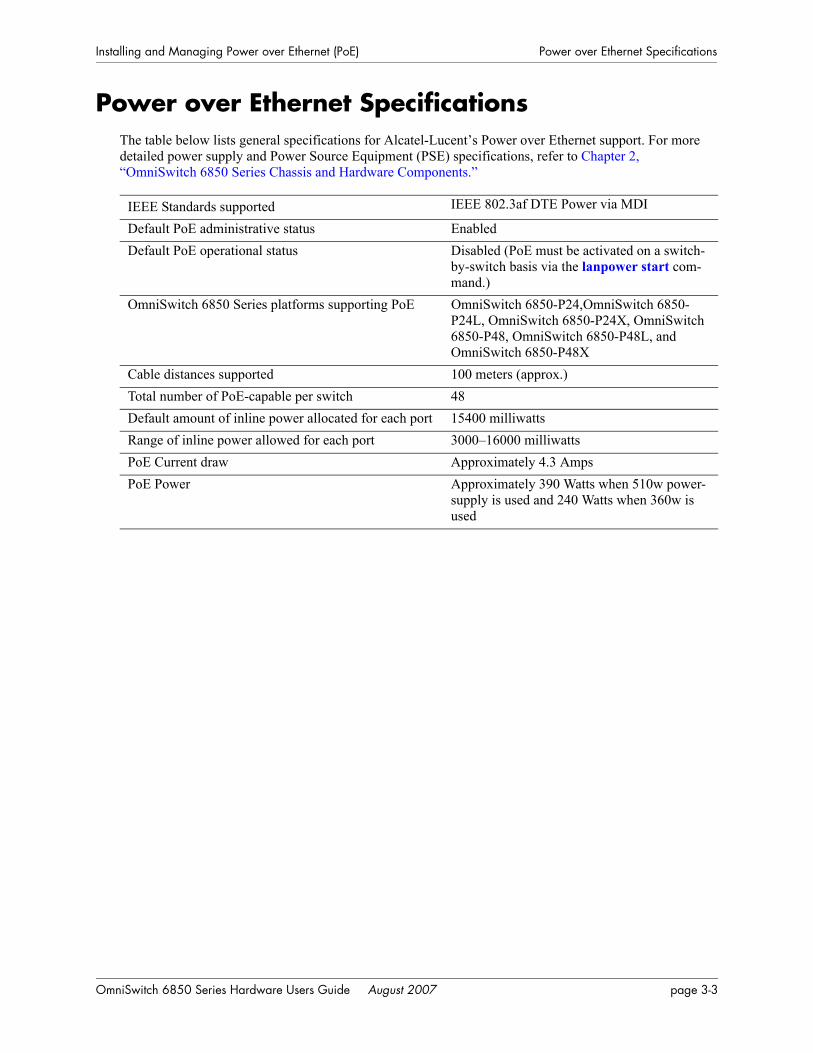
Installing and Managing Power over Ethernet (PoE) Power over Ethernet Specifications
Power over Ethernet SpecificationsThe table below lists general specifications for Alcatel-Lucent’s Power over Ethernet support. For more detailed power supply and Power Source Equipment (PSE) specifications, refer to Chapter 2, “OmniSwitch 6850 Series Chassis and Hardware Components.”
IEEE Standards supported IEEE 802.3af DTE Power via MDI
Default PoE administrative status EnabledDefault PoE operational status Disabled (PoE must be activated on a switch-
by-switch basis via the lanpower start com-mand.)
OmniSwitch 6850 Series platforms supporting PoE OmniSwitch 6850-P24,OmniSwitch 6850-P24L, OmniSwitch 6850-P24X, OmniSwitch 6850-P48, OmniSwitch 6850-P48L, and OmniSwitch 6850-P48X
Cable distances supported 100 meters (approx.)Total number of PoE-capable per switch 48Default amount of inline power allocated for each port 15400 milliwattsRange of inline power allowed for each port 3000–16000 milliwattsPoE Current draw Approximately 4.3 AmpsPoE Power Approximately 390 Watts when 510w power-
supply is used and 240 Watts when 360w is used
OmniSwitch 6850 Series Hardware Users Guide August 2007 page 3-3

Viewing PoE Power Supply Status Installing and Managing Power over Ethernet (PoE)
Viewing PoE Power Supply StatusTo view the current status of power supplies installed in the backup power supply, use the show power command, as shown below:-> show powerSlot PS Wattage Type Status Location----+----+---------+------+-----------+----------1 1 -- -- -- -- 1 2 360 AC UP External1 3 -- -- -- -- 2 1 510 AC UP External2 2 -- -- -- -- 2 3 -- -- -- -- 3 1 360 AC UP External3 2 -- -- -- -- 3 3 -- -- -- --
The backup power supply will always display as “PS-2”. For detailed information on the show power command output, refer to the CLI Command Reference Guide.
page 3-4 OmniSwitch 6850 Series Hardware Users Guide August 2007
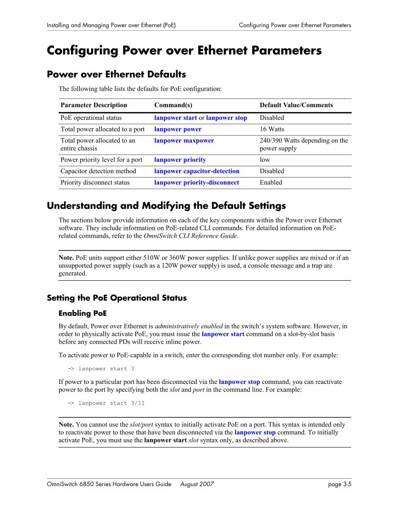
Installing and Managing Power over Ethernet (PoE) Configuring Power over Ethernet Parameters
Configuring Power over Ethernet Parameters
Power over Ethernet DefaultsThe following table lists the defaults for PoE configuration:
Understanding and Modifying the Default SettingsThe sections below provide information on each of the key components within the Power over Ethernet software. They include information on PoE-related CLI commands. For detailed information on PoE-related commands, refer to the OmniSwitch CLI Reference Guide.
Note. PoE units support either 510W or 360W power supplies. If unlike power supplies are mixed or if an unsupported power supply (such as a 120W power supply) is used, a console message and a trap are generated.
Setting the PoE Operational Status
Enabling PoE
By default, Power over Ethernet is administratively enabled in the switch’s system software. However, in order to physically activate PoE, you must issue the lanpower start command on a slot-by-slot basis before any connected PDs will receive inline power.
To activate power to PoE-capable in a switch, enter the corresponding slot number only. For example:
-> lanpower start 3
If power to a particular port has been disconnected via the lanpower stop command, you can reactivate power to the port by specifying both the slot and port in the command line. For example:
-> lanpower start 3/11
Note. You cannot use the slot/port syntax to initially activate PoE on a port. This syntax is intended only to reactivate power to those that have been disconnected via the lanpower stop command. To initially activate PoE, you must use the lanpower start slot syntax only, as described above.
Parameter Description Command(s) Default Value/Comments
PoE operational status lanpower start or lanpower stop Disabled
Total power allocated to a port lanpower power 16 Watts
Total power allocated to an entire chassis
lanpower maxpower 240/390 Watts depending on the power supply
Power priority level for a port lanpower priority low
Capacitor detection method lanpower capacitor-detection Disabled
Priority disconnect status lanpower priority-disconnect Enabled
OmniSwitch 6850 Series Hardware Users Guide August 2007 page 3-5

Configuring Power over Ethernet Parameters Installing and Managing Power over Ethernet (PoE)
Disabling PoE
To disable PoE on a particular slot or port, use the lanpower stop command.
To disable PoE on a specific PoE-capable port, enter a slot/port number. For example:
-> lanpower stop 8/22
To disable PoE for all PoE-capable in a slot, enter the corresponding slot number only. For example:
-> lanpower stop 8
Configuring the Total Power Allocated to a PortBy default, PoE automatically allocates 15400 milliwatts for each port on the OmniSwitch 6850 Series switch. In other words, each port is authorized by the system software to use up to 16000 milliwatts to power any attached device.
You can either increase or decrease this value. Values may range from 3000 to 16000 milliwatts.
Increasing the total power allocated to an individual port may provide a more demanding Powered Device (PD) with additional power required for operation. Decreasing the total power allocated to a port helps to preserve inline power and assists in the overall management of the switch’s power budget.
To increase or decrease the total power allocated to an individual port, use the lanpower power command. Since you are setting the power allowance for an individual port, you must specify a slot/port number in the command line. For example, the syntax
-> lanpower 3/12 power 3000
reduces the power allowance on port 12 of the OmniSwitch 6850 Series switch 3 to 3000 milliwatts. This new value is now the maximum amount of power the port can use to power any attached device (until the value is modified by the user).
Configuring the Total Power Allocated to a SwitchLike the maximum port power allowance, the system software also provides a maximum slot-wide power allowance. By default, each slot is authorized by the system software to use up to either 230 or 380 Watts to power all devices connected to its depending on which power supply is used.
As with the maximum port power allowance, the user can either increase or decrease this value. Values may range from 37 to 230 watts for a 360W power supply or from 37 to 380 watts for a 510 W power supply.
Increasing the total power allocated to a slot may provide more demanding Powered Devices (PDs) with additional power required for operation. Decreasing the total power allocated to a slot helps preserve inline power and assists in the overall management of the switch’s power budget.
Important. Before changing the maximum slot-wide power allowance, you must disable PoE for the slot via the lanpower stop command. Once the new value is assigned, re-enable PoE for the slot via the lanpower start command.
page 3-6 OmniSwitch 6850 Series Hardware Users Guide August 2007
Installing and Managing Power over Ethernet (PoE) Configuring Power over Ethernet Parameters
To increase or decrease the total power allocated to a slot, use the lanpower maxpower command. Since you are setting the power allowance for an individual slot, you must specify a slot number in the command line. For example, the syntax
-> lanpower 3 maxpower 80
reduces the power allowance of the OmniSwitch 6850 Series slot 3 to 80 watts. This value is now the maximum amount of power the slot can use to power all attached devices (until the value is modified by the user).
Setting Port Priority LevelsAs not all Powered Devices (PDs) connected to the switch have the same priority within a customer network setting, the OmniSwitch 6850 Series switches allow the user to specify priority levels on a port-by-port basis. Priority levels include low, high, and critical. The default priority level for a port is low.
• Low. This default value is used for port(s) that have low-priority devices attached. In the event of a power management issue, inline power to low-priority is interrupted first (i.e., before critical and high-priority).
• High. This value is used for port(s) that have important, but not mission-critical, devices attached. If other in the chassis have been configured as critical, inline power to high-priority is given second priority.
• Critical. This value is used for port(s) that have mission-critical devices attached, and therefore require top (i.e., critical) priority. In the event of a power management issue, inline power to critical is main-tained as long as possible.
To change the priority level for a particular port, use the lanpower priority command. Since the switch allows you to set priority levels on a port-by-port basis, be sure to specify slot/port information in the command line. For example, the syntax
-> lanpower 8/22 priority critical
changes the priority value of port 22 of the OmniSwitch 6850 Series slot 8 to the highest priority level of critical. Now that the default value has been reconfigured, this port should be reserved for those PDs that are mission critical for network operations.
OmniSwitch 6850 Series Hardware Users Guide August 2007 page 3-7

Configuring Power over Ethernet Parameters Installing and Managing Power over Ethernet (PoE)
Setting the Capacitor Detection MethodBy default, the PowerDsine capacitor detection method is disabled on an OmniSwitch 6850 Series switch. To enable it, use the lanpower capacitor-detection command by entering lanpower capacitor-detection followed by the slot number of the OmniSwitch 6850 Series and enable.
For example, to enable the capacitor detection method on the OmniSwitch 6850 Series switch with slot number 2, enter:
-> lanpower capacitor-detection 2 enable
To disable it, use the lanpower capacitor-detection command by entering lanpower capacitor-detec-tion followed by the slot number of the OmniSwitch 6850 Series and disable.
For example, to disable the capacitor detection method on the OmniSwitch 6850 Series switch with slot number 2, enter:
-> lanpower capacitor-detection 2 disable
Note. The capacitive detection method should only be enabled to support legacy IP phones. This feature is not compatible with IEEE specification 802.3af. Please contact your Alcatel-Lucent sales engineer or Customer Support representative to find out which Alcatel-Lucent IP phones models need capacitive detection enabled.
page 3-8 OmniSwitch 6850 Series Hardware Users Guide August 2007
Installing and Managing Power over Ethernet (PoE) Understanding Priority Disconnect
Understanding Priority DisconnectThe priority disconnect function differs from the port priority function described on page 3-7 in that it applies only to the addition of powered devices (PDs) in tight power budget conditions. Priority discon-nect is used by the system software in determining whether an incoming PD will be granted or denied power when there are too few watts remaining in the PoE power budget for an additional device. For example, if there are only 2 watts available in the current PoE power budget and a user plugs a 3.5W powered device into a PoE port, the system software must determine whether the device will be powered on. Based on priority disconnect rules, in some cases one or more existing devices may be powered down in order to accommodate the incoming device. In other cases, the incoming device will be denied power.
Priority disconnect rules involve the port priority status of an incoming device (i.e., low, high, and criti-cal), as well as the port’s physical port number (i.e., 1–24). Understanding priority disconnect rules is especially helpful in avoiding power budget deficits and the unintentional shutdown of mission-critical devices when PDs are being added in tight power budget conditions. For detailed information on how priority disconnect uses port priority and port number criteria for determining the power status of incom-ing PDs, refer to the illustrated examples on pages 3-10 through 3-11.
Reminder. Priority disconnect applies only when there is inadequate power remaining in the power budget for an incoming device.
For information on setting the priority disconnect status, refer to the section below. For information on setting the port priority status (a separate function from priority disconnect), refer to “Setting Port Priority Levels” on page 3-7.
Setting Priority Disconnect StatusBy default, priority disconnect is enabled in the switch’s system software. For information on changing the priority disconnect status, refer to the information below.
Disabling Priority DisconnectWhen priority disconnect is disabled and there is inadequate power in the budget for an additional device, power will be denied to any incoming PD, regardless of its port priority status (i.e., low, high, and criti-cal) or physical port number (i.e., 1–24).
To disable priority disconnect, use the lanpower priority-disconnect command. Since the switch allows you to set priority disconnect status on a slot-by-slot basis, be sure to specify the slot number in the command line. For example, the syntax
-> lanpower 2 priority-disconnect disable
disables the priority disconnect function on the OmniSwitch 6850 Series slot 2.
Enabling Priority DisconnectTo enable priority disconnect, use the lanpower priority-disconnect command. Be sure to specify the slot number in the command line. For example, the syntax
-> lanpower 8 priority-disconnect enable
enables priority disconnect on the OmniSwitch 6850 Series slot 8.
OmniSwitch 6850 Series Hardware Users Guide August 2007 page 3-9

Understanding Priority Disconnect Installing and Managing Power over Ethernet (PoE)
Priority Disconnect is Enabled; Same Priority Level on All PD
Reminder. Priority disconnect examples are applicable only when there is inadequate power remaining to power an incoming device.
When a PD is being connected to a port with the same priority level as all other in the slot, the physical port number is used to determine whether the incoming PD will be granted or denied power. Lower-numbered receive higher priority than higher-numbered. In other words, a PD connected to Port 1 will have a higher power priority than a PD connected to Port 2; a PD connected to Port 23 will have a higher power priority than a PD connected to Port 24. In order to avoid a power budget deficit, another port in the slot is disconnected. In determining which port to power off, the system software disconnects the port with the highest physical port number.
Priority Disconnect is Enabled; Incoming PD Port has Highest Priority Level
Reminder. Priority disconnect examples are applicable only when there is inadequate power remaining to power an incoming device.
When a PD is being connected to a port with a higher priority level than all other in the slot, the incoming PD will automatically be granted power over the other devices, regardless of its physical port number.
In order to avoid a power budget deficit, another port in the slot is disconnected. In determining which port to power off, the system software first selects the port with the lowest configured priority level. For exam-ple, if a critical priority device is being added to a slot in which five existing devices are attached to high priority and one device is attached to a low priority port, the low priority port is automatically discon-nected, regardless of its physical port number.
If all existing devices are attached to with the same lower priority level, the system software disconnects the port with both the lowest priority level and the highest physical port number. For example, if a critical priority device is being added to a slot in which six existing devices are attached to high priority, the high priority port with the highest physical port number is automatically disconnected.
Priority Disconnect is Enabled; Incoming PD Port has Lowest Priority Level
Reminder. Priority disconnect examples are applicable only when there is inadequate power remaining to power an incoming device.
When a PD is being connected to a port with a lower priority level than all other in the slot, the incoming PD will be denied power, regardless of its physical port number. Devices connected to other higher-prior-ity will continue operating without interruption.
page 3-10 OmniSwitch 6850 Series Hardware Users Guide August 2007

Installing and Managing Power over Ethernet (PoE) Understanding Priority Disconnect
Priority Disconnect is Disabled
Reminder. Priority disconnect examples are applicable only when there is inadequate power remaining to power an incoming device.
When priority disconnect is disabled, power will be denied to any incoming PD, regardless of its port priority status (i.e., low, high, and critical) or physical port number (i.e., 1–24).
OmniSwitch 6850 Series Hardware Users Guide August 2007 page 3-11

Monitoring Power over Ethernet via CLI Installing and Managing Power over Ethernet (PoE)
Monitoring Power over Ethernet via CLITo monitor current PoE statistics and settings, use the show lanpower command. The command output displays a list of all current PoE-capable, along with the following information for each port:
• Maximum power allocated to the port, in milliwatts
• Actual power used by the port
• Current port status
• Power priority status
• Power on/off status
Aggregate slot and chassis management information is also displayed. This information includes:
• Maximum watts allocated to the corresponding slot
• Amount of power budget remaining that can be allocated for PoE modules
• Total amount of power remaining that can be allocated for additional switch functions
When entering the show lanpower command, you must include a valid slot number in the command line syntax. For example: -> show lanpower 1Port Maximum(mW) Actual Used(mW) Status Priority On/Off----+-----------+---------------+-----------+---------+------ 1 16000 0 Undefined Low OFF 2 16000 0 Undefined Low OFF 3 16000 0 Undefined Low OFF 4 16000 0 Undefined Low OFF 5 16000 0 Undefined Low OFF 6 16000 0 Undefined Low OFF 7 16000 0 Undefined Low OFF 8 16000 0 Undefined Low OFF 9 16000 0 Undefined Low OFF 10 16000 0 Undefined Low OFF 11 16000 0 Undefined Low OFF 12 16000 0 Undefined Low OFF 13 16000 0 Undefined Low OFF 14 16000 0 Undefined Low OFF 15 16000 0 Undefined Low OFF 16 16000 0 Undefined Low OFF 17 16000 0 Undefined Low OFF 18 16000 0 Undefined Low OFF 19 16000 0 Undefined Low OFF 20 16000 0 Undefined Low OFF 21 16000 0 Undefined Low OFF 22 16000 0 Undefined Low OFF 23 16000 0 Undefined Low OFF 24 16000 0 Undefined Low OFF 25 16000 0 Undefined Low OFF 26 16000 0 Undefined Low OFF 27 16000 0 Undefined Low OFF 28 16000 0 Undefined Low OFF
(Output continued on next page)
page 3-12 OmniSwitch 6850 Series Hardware Users Guide August 2007

Installing and Managing Power over Ethernet (PoE) Monitoring Power over Ethernet via CLI
29 16000 0 Undefined Low OFF 30 16000 0 Undefined Low OFF 31 16000 0 Undefined Low OFF 32 16000 0 Undefined Low OFF 33 16000 0 Undefined Low OFF 34 16000 0 Undefined Low OFF 35 16000 0 Undefined Low OFF 36 16000 0 Undefined Low OFF 37 16000 0 Undefined Low OFF 38 16000 0 Undefined Low OFF 39 16000 0 Undefined Low OFF 40 16000 0 Undefined Low OFF 41 16000 0 Undefined Low OFF 42 16000 0 Undefined Low OFF 43 16000 0 Undefined Low OFF 44 16000 0 Undefined Low OFF 45 16000 0 Undefined Low OFF 46 16000 0 Undefined Low OFF 47 16000 0 Undefined Low OFF 48 16000 0 Undefined Low OFF Slot 1 Max Watts 380380 Watts Total Power Budget Remaining380 Watts Total Power Budget Available1 Power Supplies Available
Note. For detailed information on show lanpower command output, refer to the OmniSwitch CLI Refer-ence Guide.
OmniSwitch 6850 Series Hardware Users Guide August 2007 page 3-13

Monitoring Power over Ethernet via CLI Installing and Managing Power over Ethernet (PoE)
page 3-14 OmniSwitch 6850 Series Hardware Users Guide August 2007

4 Managing OmniSwitch6850 Series Stacks
In addition to their working as individual stand-alone switches, OmniSwitch 6850 Series switches can also be linked together to work as a single virtual chassis known as a stack. With stacks, users can easily expand their switching capacity simply by adding additional switches to the stack. In addition, stacks provide enhanced resiliency and redundancy features. For more information, refer to page 4-3.
Note. See Chapter 2, “OmniSwitch 6850 Series Chassis and Hardware Components,” for information on managing OmniSwitch 6850 Series switches in a stand-alone configuration.
Note. You cannot mix OS6800 and OS6850 switches in a stack.
OmniSwitch 6850 Series Hardware Users Guide August 2007 page 4-1
In This Chapter Managing OmniSwitch 6850 Series Stacks
In This ChapterThis chapter provides information on OmniSwitch 6850 Series switches configured to operate as a single virtual chassis. Topics described in the chapter include:
• OmniSwitch 6850 Series stack overview on page 4-3.
• Roles within the stack on page 4-3.
• Stack cabling on page 4-16.
• Slot numbering on page 4-19.
• Hot-Swapping modules in a stack on page 4-24.
• Reloading switches on page 4-26.
• Changing the secondary module to primary on page 4-34.
• Synchronizing switches in a stack on page 4-36.
• Monitoring the stack on page 4-37.
Note. You can also manage and monitor OmniSwitch 6850 Series stacks through WebView, Alcatel-Lucent’s embedded web-based device management application. WebView is an interactive and easy-to-use GUI that can be launched from OmniVista or a web browser. Please refer to WebView’s online documentation for more information.
page 4-2 OmniSwitch 6850 Series Hardware Users Guide August 2007

Managing OmniSwitch 6850 Series Stacks OmniSwitch 6850 Series Stack Overview
OmniSwitch 6850 Series Stack OverviewUsers can configure up to eight OmniSwitch 6850 Series switches, in any combination of OS6850-24 and OS6850-48 chassis types, into a single virtual chassis known as a stack. With stacks, switching capacity can be easily expanded simply by adding additional switches to the stack. For example, a user can start with a stack composed of two switches and add up to six additional switches to that stack as network demands increase over time.
Note. Switches should be added one at a time in a stack.
Stacks also provide enhanced resiliency and redundancy features. If a switch in a stack goes down or is taken offline, the other elements in the stack will continue to operate without disruption. In addition, when a switch auto-synchronizes at boot-up, or if the user manually synchronize the switches (see “Synchroniz-ing Switches in a Stack” on page 4-36 for more information), operating software and configuration param-eters are backed up on all switches in the stack. As a result, the original operating software and configuration parameters can be easily recovered if corrupted or otherwise lost.
Note on Terminology. In the user guides provided with your OmniSwitch 6850 Series switch, the terms stack and virtual chassis are interchangeable referring to OmniSwitch 6850 Series switches in a stacked configuration. The terms module, switch, slot, and element are used to refer to individual switches within a stacked configuration. The terms Chassis Management Module (CMM) and management module refer to those switches operating in a stack either in the primary or secondary management roles. OmniSwitch 6850 Series switches operating in an idle role are essentially acting as network interface modules and therefore may be referred to as Network Interfaces (NIs).
Roles Within the StackIn order to operate as a virtual chassis, switches within an OmniSwitch 6850 Series stack are assigned specific roles. These roles include primary and secondary management roles, idle status, and pass-through. For detailed descriptions of each of these roles, including their practical functions within the virtual chas-sis, refer to the sections below.
Primary and Secondary Management ModulesWhen OmniSwitch 6850 Series switches operate in a stack, one switch in the stack always assumes the primary management role. This primary element is responsible for functions, such as software and config-uration management, web-based management (i.e., WebView), SNMP management, switch diagnostics, and software rollback.
One additional switch in the stack operates in a secondary management role. This switch serves as a backup, and is always ready to assume the primary management role in the stack if the switch with the primary role fails or is taken offline for any reason.
Since the secondary module quickly and automatically assumes management responsibilities, switches operating in idle mode elsewhere in the stack continue to pass traffic without disruption. This redundancy provides effective safeguards for mission-critical network traffic and is one of the stack’s most important failover features. Diagrams showing the management module failover sequence for stacks of three or more switches and stacks of two switches are provided on pages 4-4 and 4-5, respectively.
OmniSwitch 6850 Series Hardware Users Guide August 2007 page 4-3
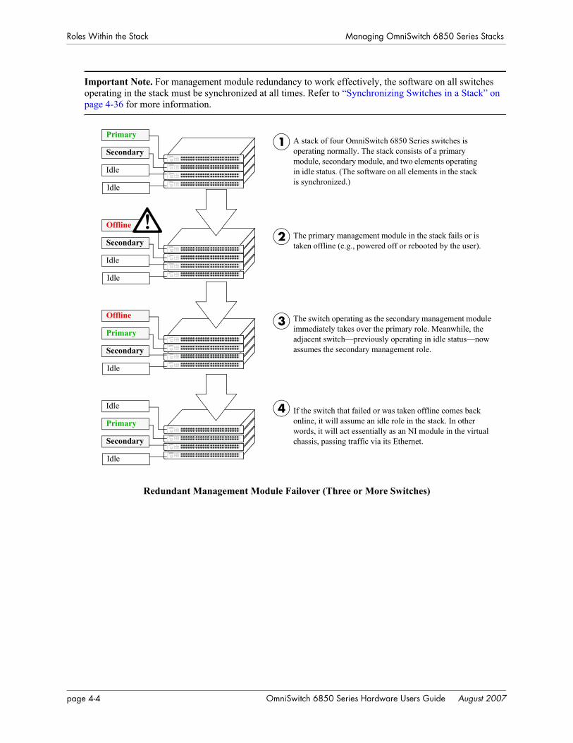
Roles Within the Stack Managing OmniSwitch 6850 Series Stacks
Important Note. For management module redundancy to work effectively, the software on all switches operating in the stack must be synchronized at all times. Refer to “Synchronizing Switches in a Stack” on page 4-36 for more information.
Redundant Management Module Failover (Three or More Switches)
Secondary
Primary
Idle
Idle
Secondary
Offline
Idle
Idle
Primary
Offline
Secondary
Idle
!
Primary
Idle
Secondary
Idle
A stack of four OmniSwitch 6850 Series switches is operating normally. The stack consists of a primary module, secondary module, and two elements operating in idle status. (The software on all elements in the stack is synchronized.)
The primary management module in the stack fails or is taken offline (e.g., powered off or rebooted by the user).
The switch operating as the secondary management module immediately takes over the primary role. Meanwhile, the adjacent switch—previously operating in idle status—now assumes the secondary management role.
If the switch that failed or was taken offline comes back online, it will assume an idle role in the stack. In other words, it will act essentially as an NI module in the virtual chassis, passing traffic via its Ethernet.
1
2
3
4
page 4-4 OmniSwitch 6850 Series Hardware Users Guide August 2007
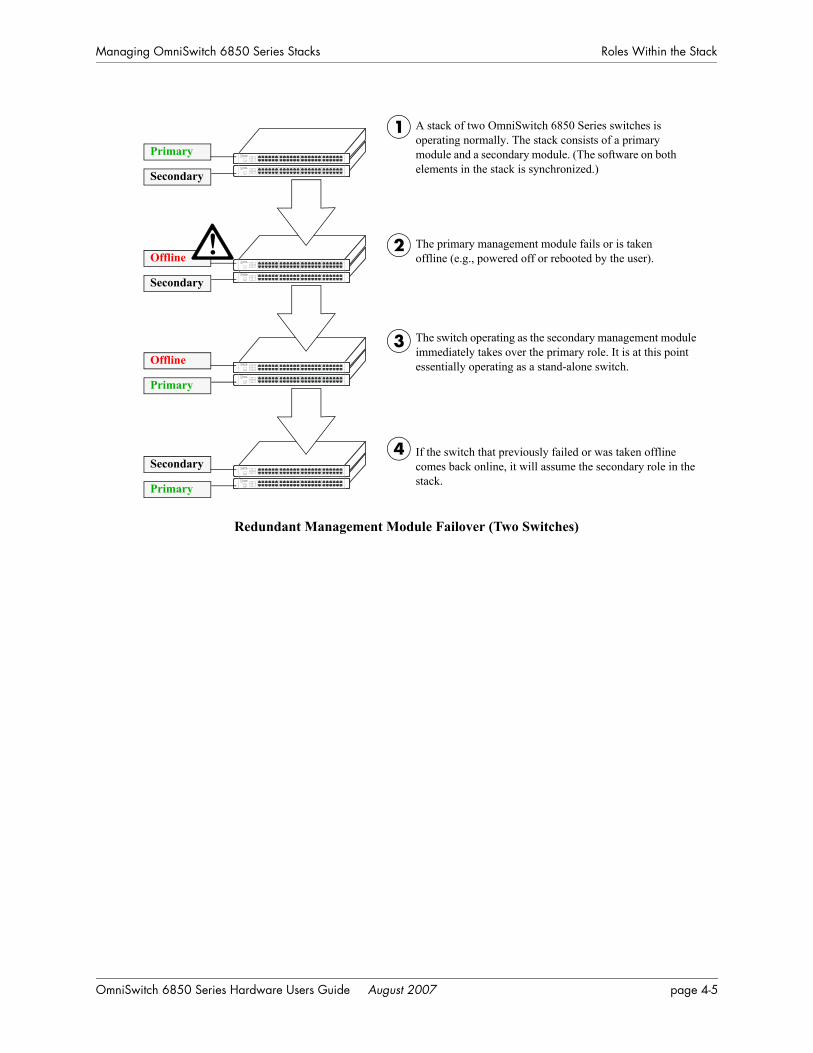
Managing OmniSwitch 6850 Series Stacks Roles Within the Stack
Redundant Management Module Failover (Two Switches)
Primary
Secondary
Secondary
Offline
Primary
Offline
Secondary
Primary
!
A stack of two OmniSwitch 6850 Series switches is operating normally. The stack consists of a primary module and a secondary module. (The software on both elements in the stack is synchronized.)
The primary management module fails or is taken offline (e.g., powered off or rebooted by the user).
The switch operating as the secondary management module immediately takes over the primary role. It is at this point essentially operating as a stand-alone switch.
If the switch that previously failed or was taken offline comes back online, it will assume the secondary role in the stack.
1
2
3
4
OmniSwitch 6850 Series Hardware Users Guide August 2007 page 4-5
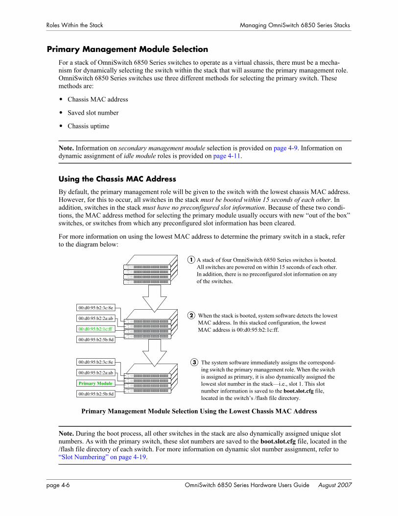
Roles Within the Stack Managing OmniSwitch 6850 Series Stacks
Primary Management Module SelectionFor a stack of OmniSwitch 6850 Series switches to operate as a virtual chassis, there must be a mecha-nism for dynamically selecting the switch within the stack that will assume the primary management role. OmniSwitch 6850 Series switches use three different methods for selecting the primary switch. These methods are:
• Chassis MAC address
• Saved slot number
• Chassis uptime
Note. Information on secondary management module selection is provided on page 4-9. Information on dynamic assignment of idle module roles is provided on page 4-11.
Using the Chassis MAC Address
By default, the primary management role will be given to the switch with the lowest chassis MAC address. However, for this to occur, all switches in the stack must be booted within 15 seconds of each other. In addition, switches in the stack must have no preconfigured slot information. Because of these two condi-tions, the MAC address method for selecting the primary module usually occurs with new “out of the box” switches, or switches from which any preconfigured slot information has been cleared.
For more information on using the lowest MAC address to determine the primary switch in a stack, refer to the diagram below:
Primary Management Module Selection Using the Lowest Chassis MAC Address
Note. During the boot process, all other switches in the stack are also dynamically assigned unique slot numbers. As with the primary switch, these slot numbers are saved to the boot.slot.cfg file, located in the /flash file directory of each switch. For more information on dynamic slot number assignment, refer to “Slot Numbering” on page 4-19.
A stack of four OmniSwitch 6850 Series switches is booted. All switches are powered on within 15 seconds of each other. In addition, there is no preconfigured slot information on any of the switches.
00:d0:95:b2:3c:8e
00:d0:95:b2:2a:ab
00:d0:95:b2:1c:ff
00:d0:95:b2:5b:8d
When the stack is booted, system software detects the lowest MAC address. In this stacked configuration, the lowest MAC address is 00:d0:95:b2:1c:ff.
2
1
00:d0:95:b2:3c:8e
00:d0:95:b2:2a:ab
Primary Module
00:d0:95:b2:5b:8d
The system software immediately assigns the correspond-ing switch the primary management role. When the switch is assigned as primary, it is also dynamically assigned the lowest slot number in the stack—i.e., slot 1. This slot number information is saved to the boot.slot.cfg file, located in the switch’s /flash file directory.
3
page 4-6 OmniSwitch 6850 Series Hardware Users Guide August 2007
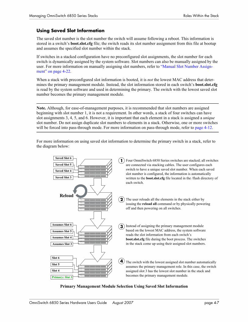
Managing OmniSwitch 6850 Series Stacks Roles Within the Stack
Using Saved Slot Information
The saved slot number is the slot number the switch will assume following a reboot. This information is stored in a switch’s boot.slot.cfg file; the switch reads its slot number assignment from this file at bootup and assumes the specified slot number within the stack.
If switches in a stacked configuration have no preconfigured slot assignments, the slot number for each switch is dynamically assigned by the system software. Slot numbers can also be manually assigned by the user. For more information on manually assigning slot numbers, refer to “Manual Slot Number Assign-ment” on page 4-22.
When a stack with preconfigured slot information is booted, it is not the lowest MAC address that deter-mines the primary management module. Instead, the slot information stored in each switch’s boot.slot.cfg is read by the system software and used in determining the primary. The switch with the lowest saved slot number becomes the primary management module.
Note. Although, for ease-of-management purposes, it is recommended that slot numbers are assigned beginning with slot number 1, it is not a requirement. In other words, a stack of four switches can have slot assignments 3, 4, 5, and 6. However, it is important that each element in a stack is assigned a unique slot number. Do not assign duplicate slot numbers to elements in a stack. Otherwise, one or more switches will be forced into pass-through mode. For more information on pass-through mode, refer to page 4-12.
For more information on using saved slot information to determine the primary switch in a stack, refer to the diagram below:
Primary Management Module Selection Using Saved Slot Information
Slot 6
Slot 5
Slot 4
Primary: Slot 3
Assumes Slot 6
Assumes Slot 5
Assumes Slot 4
Assumes Slot 3
Saved Slot 6Four OmniSwitch 6850 Series switches are stacked; all switches are connected via stacking cables. The user configures each switch to have a unique saved slot number. When each saved slot number is configured, the information is automatically written to the boot.slot.cfg file located in the /flash directory of each switch.
The user reloads all the elements in the stack either by issuing the reload all command or by physically powering off and then powering on all switches.
Instead of assigning the primary management module based on the lowest MAC address, the system software reads the slot information from each switch’s boot.slot.cfg file during the boot process. The switches in the stack come up using their assigned slot numbers.
The switch with the lowest assigned slot number automatically assumes the primary management role. In this case, the switch assigned slot 3 has the lowest slot number in the stack and becomes the primary management module.
1
2
3
4
Saved Slot 5
Saved Slot 4
Saved Slot 3
Reload
OmniSwitch 6850 Series Hardware Users Guide August 2007 page 4-7
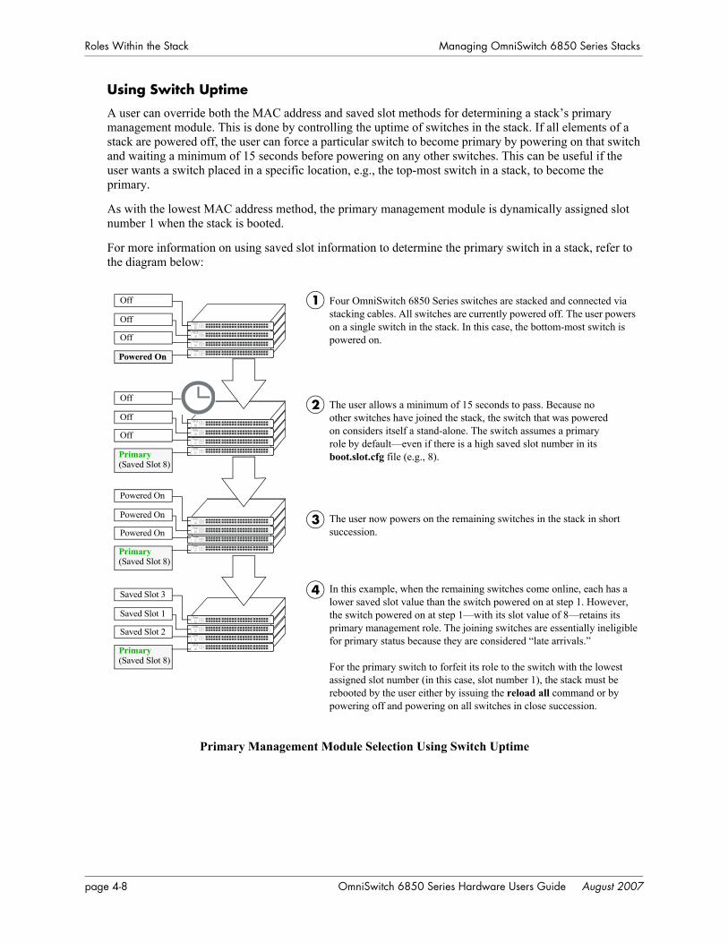
Roles Within the Stack Managing OmniSwitch 6850 Series Stacks
Using Switch Uptime
A user can override both the MAC address and saved slot methods for determining a stack’s primary management module. This is done by controlling the uptime of switches in the stack. If all elements of a stack are powered off, the user can force a particular switch to become primary by powering on that switch and waiting a minimum of 15 seconds before powering on any other switches. This can be useful if the user wants a switch placed in a specific location, e.g., the top-most switch in a stack, to become the primary.
As with the lowest MAC address method, the primary management module is dynamically assigned slot number 1 when the stack is booted.
For more information on using saved slot information to determine the primary switch in a stack, refer to the diagram below:
Primary Management Module Selection Using Switch Uptime
Powered On
Powered On
Powered On
Off Four OmniSwitch 6850 Series switches are stacked and connected via stacking cables. All switches are currently powered off. The user powers on a single switch in the stack. In this case, the bottom-most switch is powered on.
The user now powers on the remaining switches in the stack in short succession.
In this example, when the remaining switches come online, each has a lower saved slot value than the switch powered on at step 1. However, the switch powered on at step 1—with its slot value of 8—retains its primary management role. The joining switches are essentially ineligible for primary status because they are considered “late arrivals.”
For the primary switch to forfeit its role to the switch with the lowest assigned slot number (in this case, slot number 1), the stack must be rebooted by the user either by issuing the reload all command or by powering off and powering on all switches in close succession.
1
2
3
Off
Off
Powered On
Off
Off
Off
Primary(Saved Slot 8)
Primary(Saved Slot 8)
Saved Slot 3
Saved Slot 1
Saved Slot 2
Primary(Saved Slot 8)
The user allows a minimum of 15 seconds to pass. Because no other switches have joined the stack, the switch that was powered on considers itself a stand-alone. The switch assumes a primary role by default—even if there is a high saved slot number in its boot.slot.cfg file (e.g., 8).
4
page 4-8 OmniSwitch 6850 Series Hardware Users Guide August 2007
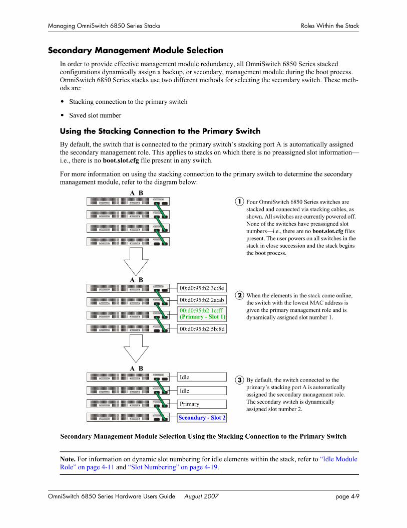
Managing OmniSwitch 6850 Series Stacks Roles Within the Stack
Secondary Management Module SelectionIn order to provide effective management module redundancy, all OmniSwitch 6850 Series stacked configurations dynamically assign a backup, or secondary, management module during the boot process. OmniSwitch 6850 Series stacks use two different methods for selecting the secondary switch. These meth-ods are:
• Stacking connection to the primary switch
• Saved slot number
Using the Stacking Connection to the Primary Switch
By default, the switch that is connected to the primary switch’s stacking port A is automatically assigned the secondary management role. This applies to stacks on which there is no preassigned slot information—i.e., there is no boot.slot.cfg file present in any switch.
For more information on using the stacking connection to the primary switch to determine the secondary management module, refer to the diagram below:
Secondary Management Module Selection Using the Stacking Connection to the Primary Switch
Note. For information on dynamic slot numbering for idle elements within the stack, refer to “Idle Module Role” on page 4-11 and “Slot Numbering” on page 4-19.
Four OmniSwitch 6850 Series switches are stacked and connected via stacking cables, as shown. All switches are currently powered off. None of the switches have preassigned slot numbers—i.e., there are no boot.slot.cfg files present. The user powers on all switches in the stack in close succession and the stack begins the boot process.
By default, the switch connected to the primary’s stacking port A is automatically assigned the secondary management role. The secondary switch is dynamically assigned slot number 2.
1
2
3
When the elements in the stack come online, the switch with the lowest MAC address is given the primary management role and is dynamically assigned slot number 1.
A B
A B
A B
00:d0:95:b2:3c:8e
00:d0:95:b2:2a:ab
00:d0:95:b2:1c:ff
00:d0:95:b2:5b:8d
Idle
Idle
Primary
Secondary - Slot 2
(Primary - Slot 1)
OmniSwitch 6850 Series Hardware Users Guide August 2007 page 4-9
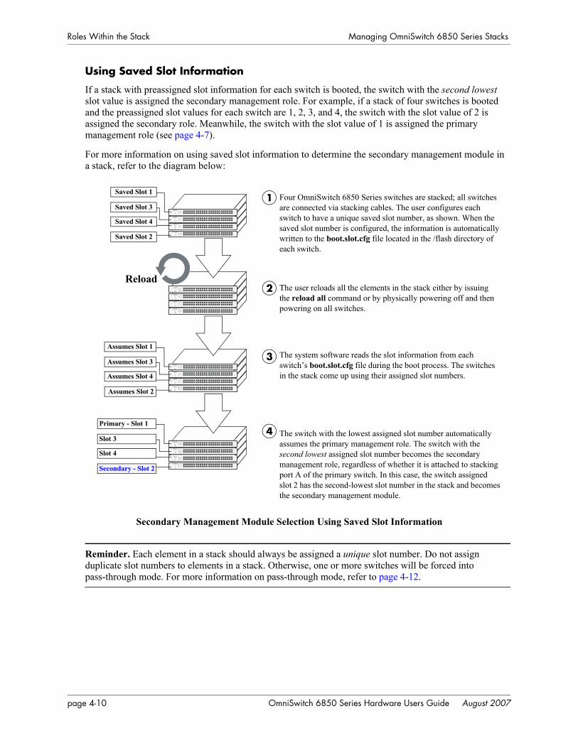
Roles Within the Stack Managing OmniSwitch 6850 Series Stacks
Using Saved Slot Information
If a stack with preassigned slot information for each switch is booted, the switch with the second lowest slot value is assigned the secondary management role. For example, if a stack of four switches is booted and the preassigned slot values for each switch are 1, 2, 3, and 4, the switch with the slot value of 2 is assigned the secondary role. Meanwhile, the switch with the slot value of 1 is assigned the primary management role (see page 4-7).
For more information on using saved slot information to determine the secondary management module in a stack, refer to the diagram below:
Secondary Management Module Selection Using Saved Slot Information
Reminder. Each element in a stack should always be assigned a unique slot number. Do not assign duplicate slot numbers to elements in a stack. Otherwise, one or more switches will be forced into pass-through mode. For more information on pass-through mode, refer to page 4-12.
Primary - Slot 1
Slot 3
Slot 4
Secondary - Slot 2
Assumes Slot 1
Assumes Slot 3
Assumes Slot 4
Assumes Slot 2
Saved Slot 1Four OmniSwitch 6850 Series switches are stacked; all switches are connected via stacking cables. The user configures each switch to have a unique saved slot number, as shown. When the saved slot number is configured, the information is automatically written to the boot.slot.cfg file located in the /flash directory of each switch.
The user reloads all the elements in the stack either by issuing the reload all command or by physically powering off and then powering on all switches.
The system software reads the slot information from each switch’s boot.slot.cfg file during the boot process. The switches in the stack come up using their assigned slot numbers.
The switch with the lowest assigned slot number automatically assumes the primary management role. The switch with the second lowest assigned slot number becomes the secondary management role, regardless of whether it is attached to stacking port A of the primary switch. In this case, the switch assigned slot 2 has the second-lowest slot number in the stack and becomes the secondary management module.
1
2
3
4
Saved Slot 3
Saved Slot 4
Saved Slot 2
Reload
page 4-10 OmniSwitch 6850 Series Hardware Users Guide August 2007
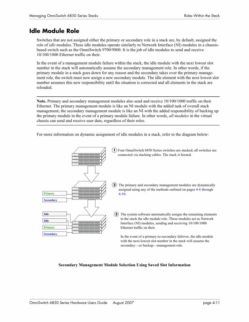
Managing OmniSwitch 6850 Series Stacks Roles Within the Stack
Idle Module RoleSwitches that are not assigned either the primary or secondary role in a stack are, by default, assigned the role of idle modules. These idle modules operate similarly to Network Interface (NI) modules in a chassis-based switch such as the OmniSwitch 9700/9800. It is the job of idle modules to send and receive 10/100/1000 Ethernet traffic on their.
In the event of a management module failure within the stack, the idle module with the next lowest slot number in the stack will automatically assume the secondary management role. In other words, if the primary module in a stack goes down for any reason and the secondary takes over the primary manage-ment role, the switch must now assign a new secondary module. The idle element with the next lowest slot number assumes this new responsibility until the situation is corrected and all elements in the stack are reloaded.
Note. Primary and secondary management modules also send and receive 10/100/1000 traffic on their Ethernet. The primary management module is like an NI module with the added task of overall stack management; the secondary management module is like an NI with the added responsibility of backing up the primary module in the event of a primary module failure. In other words, all modules in the virtual chassis can send and receive user data, regardless of their roles.
For more information on dynamic assignment of idle modules in a stack, refer to the diagram below:
Secondary Management Module Selection Using Saved Slot Information
Four OmniSwitch 6850 Series switches are stacked; all switches are connected via stacking cables. The stack is booted.
Primary
Secondary
The primary and secondary management modules are dynamically assigned using any of the methods outlined on pages 4-6 through 4-10.
2
1
Idle
Idle
Primary
Secondary
The system software automatically assigns the remaining elements in the stack the idle module role. These modules act as Network Interface (NI) modules, sending and receiving 10/100/1000 Ethernet traffic on their.
In the event of a primary-to-secondary failover, the idle module with the next-lowest slot number in the stack will assume the secondary—or backup—management role.
3
OmniSwitch 6850 Series Hardware Users Guide August 2007 page 4-11
Roles Within the Stack Managing OmniSwitch 6850 Series Stacks
Pass-Through ModeThe pass-through mode is a state in which a switch has attempted to join a stack but has been denied primary, secondary, and idle status. When a switch is in the pass-through mode, its Ethernet are brought down (i.e, they cannot pass traffic). Its stacking cable connections remain fully functional and can pass traffic through to other switches in the stack. In this way, the pass-through mode provides a mechanism to prevent the stack ring from being broken. However, note that when a switch comes up in pass-through mode, it should not be left unresolved. Pass-through mode is essentially an error state that should be corrected immediately by the user.
Note. When a switch is in pass-through mode, its information will not display in hardware monitoring commands such as show chassis, show ni, show module, etc.
Conditions that can trigger a switch to enter pass-through mode include:
• Duplicate slot numbers have been assigned within the stack
• The user has manually forced the switch into pass-through mode using the stack clear slot command
Note. If a switch is forced into pass-through mode, the rest of the stack will not be disrupted. Any elements in the stack not operating in pass-through mode continue to operate normally.
The most common reason for one or more switches to enter pass-through is duplicate slot number assign-ments within the stack. So, in order to avoid pass-through mode, it is useful to keep track of the current saved slot numbers on all elements in the stack. Slot number assignments are stored in the boot.slot.cfg file in the /flash directory of each switch.
If the stack is booted and the same slot number is discovered on two or more switches, the switch with the lowest MAC address is allowed to come up and operate normally. Meanwhile, switches with the duplicate slot number and a higher MAC address come up in pass-through mode. To check the current slot number stored in each switch’s boot.slot.cfg file, use the show stack topology command. For example:
-> show stack topology Link A Link A Link B Link BNI Role State Saved Link A Remote Remote Link B Remote Remote Slot State NI Port State NI Port----+-----------+--------+------+-------+-------+-------+-------+-------+------- 1 PRIMARY RUNNING 1 UP 3 StackA UP 2 StackA 2 SECONDARY RUNNING 2 UP 1 StackB UP 3 StackB 3 IDLE RUNNING 2 UP 1 StackA UP 2 StackB
In this example, note that both slots 2 and 3 have a saved slot value of 2. If this stack is rebooted, a dupli-cate slot error will occur and the switch with the lower MAC address will be given the secondary manage-ment role. The slot with the higher MAC address will be forced into the pass-through mode.
page 4-12 OmniSwitch 6850 Series Hardware Users Guide August 2007

Managing OmniSwitch 6850 Series Stacks Roles Within the Stack
To avoid a pass-through condition following a reboot, make sure that all saved slot values for the stack are unique. Use the stack set slot command. For example, change the saved slot value for the idle switch in slot 3 from 2 to 3:
-> stack set slot 3 saved-slot 2
Use the show stack topology command to verify the change:
-> show stack topology Link A Link A Link B Link BNI Role State Saved Link A Remote Remote Link B Remote Remote Slot State NI Port State NI Port----+-----------+--------+------+-------+-------+-------+-------+-------+------- 1 PRIMARY RUNNING 1 UP 3 StackA UP 2 StackA 2 SECONDARY RUNNING 2 UP 1 StackB UP 3 StackB 3 IDLE RUNNING 3 UP 1 StackA UP 2 StackB
Recovering from Pass-Through Mode (Duplicate Slot Numbers) The first step in recovering from pass-through is to determine which modules are currently operating in pass-through, as well as the reason for the pass-through state. To view this information, use the show stack topology command. For example:
-> show stack topology Link A Link A Link B Link BNI Role State Saved Link A Remote Remote Link B Remote Remote Slot State NI Port State NI Port----+-----------+--------+------+-------+-------+-------+-------+-------+------- 1 PRIMARY RUNNING 1 UP 1001 StackA UP 2 StackA 2 SECONDARY RUNNING 2 UP 1 StackB UP 1001 StackB1001 PASS-THRU DUP-SLOT 2 UP 1 StackA UP 2 StackB
Switches operating in pass-through mode are given distinct slot numbers. These slot numbers are not related to their position in the stack. Instead, they are assigned the prefix “100,” followed by the numeri-cal order in which they were forced into pass-through (1001–1008).
Note. For pass-through elements 1001 through 1008, the slot indicator LED on the chassis front panel blinks 1 through 8, respectively. For example, if a module enters pass-through and has the slot number 1004, the LED for the module blinks the number 4. For more information on the slot indicator LED, refer to “Status LEDs” on page 2-54.
In the example above, the switch with the NI (i.e., slot) number 1001 is operating in pass-through. Note that the role assignment is PASS-THRU; also, the state displays DUP-SLOT, or duplicate slot number. This can be further verified by looking down the saved slot column in the table. Note that slot 2, operating in the secondary management role, has a saved slot value of 2. Slot 1001, operating in pass-through, also has a saved slot value of 2.
OmniSwitch 6850 Series Hardware Users Guide August 2007 page 4-13

Roles Within the Stack Managing OmniSwitch 6850 Series Stacks
To resolve this pass-through condition, simply assign slot 1001 a new saved slot value and reboot the module. This can be done in either of two ways:
• Use the stack set slot command to assign the new value, then use the reload pass-through command to reboot the module:
-> stack set slot 1001 saved-slot 3-> reload pass-through 1001
• Use the stack set slot command to assign the new slot value and, using the optional reload syntax in the command line, reboot the module:
-> stack set slot 1001 saved-slot 3 reload
When the module comes up, it assumes the new, unique slot position—in this case, slot 3—and, because it now has the highest slot number in the stack, it assumes an idle role (leaving the primary and secondary roles to slots 1 and 2, respectively). There are now no duplicate numbers in the stack and all elements are operating normally:
-> show stack topology Link A Link A Link B Link BNI Role State Saved Link A Remote Remote Link B Remote Remote Slot State NI Port State NI Port----+-----------+--------+------+-------+-------+-------+-------+-------+------- 1 PRIMARY RUNNING 1 UP 3 StackA UP 2 StackA 2 SECONDARY RUNNING 2 UP 1 StackB UP 3 StackB 3 IDLE RUNNING 3 UP 1 StackA UP 2 StackB
page 4-14 OmniSwitch 6850 Series Hardware Users Guide August 2007

Managing OmniSwitch 6850 Series Stacks Roles Within the Stack
In some pass-through conditions (for example, larger stacks where multiple switches are in pass-through mode), it might be desirable to correct any duplicate saved slot assignments and then reboot the entire stack. The recovery from pass-through can be accomplished with fewer steps than reassigning slot numbers and rebooting modules on a slot-by-slot basis. However, be sure that there is no mission-critical traffic being passed on the non-pass-though modules; traffic will be interrupted on these modules during the reboot.
The following example shows a large stack with multiple elements operating in pass-through mode:
-> show stack topology Link A Link A Link B Link BNI Role State Saved Link A Remote Remote Link B Remote Remote Slot State NI Port State NI Port----+-----------+--------+------+-------+-------+-------+-------+-------+------- 4 IDLE RUNNING 4 UP 5 StackB UP 3 StackA 5 IDLE RUNNING 5 UP 1001 StackB UP 4 StackA1001 PASS-THRU DUP-SLOT 2 UP 2 StackB UP 5 StackA 2 SECONDARY RUNNING 2 UP 1003 StackB UP 1001 StackA1003 PASS-THRU DUP-SLOT 2 UP 1002 StackB UP 2 StackA1002 PASS-THRU DUP-SLOT 2 UP 1 StackB UP 1003 StackA 1 PRIMARY RUNNING 1 UP 3 StackB UP 1002 StackA 3 IDLE RUNNING 3 UP 4 StackB UP 1 StackA
This disordered stack topology, with its three modules operating in pass-through mode, can be corrected by entering the following commands:
-> stack set slot 4 saved-slot 1-> stack set slot 5 saved-slot 2-> stack set slot 1001 saved-slot 3-> stack set slot 2 saved-slot 4-> stack set slot 1003 saved-slot 5-> stack set slot 1002 saved-slot 6-> stack set slot 1 saved-slot 7-> stack set slot 3 saved-slot 8-> reload all
When all elements in the stack come up following the reboot, there are no longer any duplicate slot numbers in the stack. In addition, the stack topology is more orderly and, as a result, easier to manage:
-> show stack topology Link A Link A Link B Link BNI Role State Saved Link A Remote Remote Link B Remote Remote Slot State NI Port State NI Port----+-----------+--------+------+-------+-------+-------+-------+-------+------- 1 PRIMARY RUNNING 1 UP 2 StackB UP 8 StackA 2 SECONDARY RUNNING 2 UP 3 StackB UP 1 StackA 3 IDLE RUNNING 3 UP 4 StackB UP 2 StackA 4 IDLE RUNNING 4 UP 5 StackB UP 3 StackA 5 IDLE RUNNING 5 UP 6 StackB UP 4 StackA 6 IDLE RUNNING 6 UP 7 StackB UP 5 StackA 7 IDLE RUNNING 7 UP 8 StackB UP 6 StackA 8 IDLE RUNNING 8 UP 1 StackB UP 7 StackA
OmniSwitch 6850 Series Hardware Users Guide August 2007 page 4-15
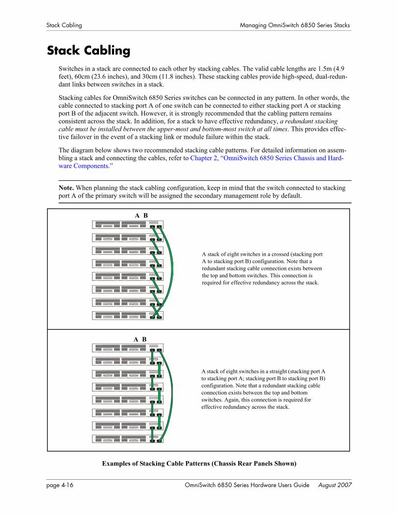
Stack Cabling Managing OmniSwitch 6850 Series Stacks
Stack CablingSwitches in a stack are connected to each other by stacking cables. The valid cable lengths are 1.5m (4.9 feet), 60cm (23.6 inches), and 30cm (11.8 inches). These stacking cables provide high-speed, dual-redun-dant links between switches in a stack.
Stacking cables for OmniSwitch 6850 Series switches can be connected in any pattern. In other words, the cable connected to stacking port A of one switch can be connected to either stacking port A or stacking port B of the adjacent switch. However, it is strongly recommended that the cabling pattern remains consistent across the stack. In addition, for a stack to have effective redundancy, a redundant stacking cable must be installed between the upper-most and bottom-most switch at all times. This provides effec-tive failover in the event of a stacking link or module failure within the stack.
The diagram below shows two recommended stacking cable patterns. For detailed information on assem-bling a stack and connecting the cables, refer to Chapter 2, “OmniSwitch 6850 Series Chassis and Hard-ware Components.”
Note. When planning the stack cabling configuration, keep in mind that the switch connected to stacking port A of the primary switch will be assigned the secondary management role by default.
Examples of Stacking Cable Patterns (Chassis Rear Panels Shown)
A stack of eight switches in a crossed (stacking port A to stacking port B) configuration. Note that a redundant stacking cable connection exists between the top and bottom switches. This connection is required for effective redundancy across the stack.
A stack of eight switches in a straight (stacking port A to stacking port A; stacking port B to stacking port B) configuration. Note that a redundant stacking cable connection exists between the top and bottom switches. Again, this connection is required for effective redundancy across the stack.
A B
A B
page 4-16 OmniSwitch 6850 Series Hardware Users Guide August 2007
Managing OmniSwitch 6850 Series Stacks Stack Cabling
Redundant Stacking Cable ConnectionOmniSwitch 6850 Series switches allow redundant stacking cable connections between the top-most and bottom-most switches in a stack.
Important. For a stacked configuration to have effective redundancy, a redundant stacking cable must be installed between the upper-most and bottom-most switch in the chassis at all times.
The figure below shows how the redundant connection between the top and bottom switches in the stack ensures that data will continue to flow throughout the stack, even in the event of a connection failure at one of the stacking cables.
Stacking Cable Redundancy: Recovery Following a Stacking Link Failure
Data enters slot 1 via a 10/100/1000 Ethernet port. The data is passed to slot 2 over the stacking cable connection, then exits slot 2 via one of its 10/100/1000 Ethernet.
1
2 The stacking connection between slots 1 and 2 goes down unexpectedly. Data can no longer travel directly between slot 1 and 2.
However, because there is a redundant connection (the cable between slot 1 and slot 4), data is immediately passed to slot 4, then quickly traverses slot 3 and exits slot 2 to its destination.
Slot 1
Slot 2
Slot 3
Slot 4
Chassis FrontStacking Cables
Slot 1
Slot 2
Slot 3
Slot 4
OmniSwitch 6850 Series Hardware Users Guide August 2007 page 4-17
Stack Cabling Managing OmniSwitch 6850 Series Stacks
Redundant stacking cables provide a form of dual redundancy. As shown in the figure above, the redun-dant cable allows traffic to flow in the event of a stacking link failure. The redundant cable also provides failover if a switch goes down within the stack. Traffic continues to flow between the modules that remain operational, as shown in the diagram below:
Stacking Cable Redundancy: Recovery Following a Switch Failure within the Stack
Checking Redundant Stacking Cable StatusTo check whether a redundant stacking cable connection exists between the top-most and bottom-most switches in the stack, use the show stack status command. For example:
-> show stack statusRedundant cable status : presentTokens used : 12Tokens available : 20
In this example, a redundant stacking cable connection is present between the top-most and bottom-most switches in the stack.
Slot 1
Slot 2
Slot 3
Slot 4
Chassis FrontStacking Cables
Data enters slot 1 through a 10/100/1000 Ethernet port. The data traverses slot 2 via the stacking cables and exits slot 3 through one of its 10/100/1000 Ethernet.
1
2 The slot 2 switch goes down unexpectedly. Data can no longer move through slot 2.
However, because there is a redundant connection (the cable between slot 1 and slot 4), data immediately traverses slot 4 and then exits slot 3 to its destination.
Slot 1
Slot 2
Slot 3
Slot 4
page 4-18 OmniSwitch 6850 Series Hardware Users Guide August 2007

Managing OmniSwitch 6850 Series Stacks Slot Numbering
Slot NumberingFor a stack of OmniSwitch 6850 Series switches to operate as a virtual chassis, each module in the stack must be assigned a unique slot number. To view the current slot assignments for a stack, use the show ni or show module commands. The slot number is also displayed on the front panel of each switch by the LED located on the left side of the chassis (refer to “Status LEDs” on page 2-54 for more information).
There are two ways stacking modules are assigned slot numbers:
• Dynamic slot number assignment by the system software
• Manual slot number assignment by the user
OmniSwitch 6850 Series Hardware Users Guide August 2007 page 4-19
Slot Numbering Managing OmniSwitch 6850 Series Stacks
Dynamic Slot Number AssignmentDynamic slot number assignment occurs when there are no boot.slot.cfg files present in the switches’ /flash directories. This is the case for new, “out of the box,” switches that have not been previously booted.
When a brand new stack (or stack with no boot.slot.cfg files) is booted, the system software automatically detects the module with the lowest MAC address. This module is assigned the primary management role (see page 4-3) and, by default, is given the slot number 1. The module connected to the primary’s stacking port A is automatically assigned the secondary management role and given the slot number 2.
As the other modules in the stack become operational, they are assigned idle roles and are automatically assigned unique slot numbers (3–8, depending on the number of switches in the stack). The slot number-ing for idle modules is determined by each module’s physical location in the stack. Refer to the diagrams below for more information on dynamic slot numbering.
Note. As the slot numbers are dynamically assigned, boot.slot.cfg files are auto-generated in the /flash directory of each switch. When modules are subsequently booted, each switch reads its slot number assignment from this file and comes up accordingly.
Dynamic Slot Numbering Example 1
Slot 1 - Primary
Slot 2 - Secondary
Slot 3 - Idle
In this example, the fourth switch from the top is elected the primary management module for the stack. (It can be assumed that this switch has the lowest MAC address in the stack.) This switch is automatically assigned slot number 1.
The switch immediately below is connected to the primary switch’s stacking port A and, as a result, is assigned the secondary management role and given slot number 2.
The system software allows the switch immediately below slot 2 to have the next slot number preference. It is assigned an idle role and given the slot number 3. The switch immediately below slot 3 is given the slot number 4, and so on. When the bottom of the stack is reached, the slot numbering sequence resumes at the top of the stack, as shown. This helps ensure a more ordered and manageable stack topology.
Slot 4 - Idle
Slot 5 - Idle
Slot 6 - Idle
Slot 7 - Idle
Slot 8 - Idle
page 4-20 OmniSwitch 6850 Series Hardware Users Guide August 2007
Managing OmniSwitch 6850 Series Stacks Slot Numbering
If the switch with the lowest MAC address happens to be the bottom-most module in the stack, slot numbering will not resume from the top of the stack. Instead, the system software will select the second-ary module using the standard method (i.e., the switch connected to the primary’s stacking port A), then continue to number the stack from the bottom up. This intuitive slot assignment provides the cleanest and most manageable stack topology. Refer to the diagram below for more information:
Dynamic Slot Numbering Example 2
Slot 5 - Idle
Slot 4 - Idle
Slot 3 - Idle
In this example, the bottom switch is elected the primary management module for the stack. (It can be assumed that this switch has the low-est MAC address in the stack.) This switch is automatically assigned slot number 1.
The switch immediately above is connected to the primary switch’s stacking port A and, as a result, is assigned the secondary management role and given slot number 2.
The system software then sequentially assigns slot numbers up the stack. In other words, the switch immediately above slot 2 is assigned the slot number 3; the switch immediately above slot 3 is assigned the slot number 4, and so on. This default procedure ensures the most ordered and manageable stack topology out of the box.
Slot 2 - Secondary
Slot 1 - Primary
Slot 8 - Idle
Slot 7 - Idle
Slot 6 - Idle
OmniSwitch 6850 Series Hardware Users Guide August 2007 page 4-21
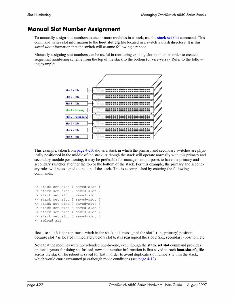
Slot Numbering Managing OmniSwitch 6850 Series Stacks
Manual Slot Number AssignmentTo manually assign slot numbers to one or more modules in a stack, use the stack set slot command. This command writes slot information to the boot.slot.cfg file located in a switch’s /flash directory. It is this saved slot information that the switch will assume following a reboot.
Manually assigning slot numbers can be useful in reordering existing slot numbers in order to create a sequential numbering scheme from the top of the stack to the bottom (or vice-versa). Refer to the follow-ing example:
This example, taken from page 4-20, shows a stack in which the primary and secondary switches are phys-ically positioned in the middle of the stack. Although the stack will operate normally with this primary and secondary module positioning, it may be preferable for management purposes to have the primary and secondary switches at either the top or the bottom of the stack. For this example, the primary and second-ary roles will be assigned to the top of the stack. This is accomplished by entering the following commands:
-> stack set slot 6 saved-slot 1-> stack set slot 7 saved-slot 2-> stack set slot 8 saved-slot 3-> stack set slot 1 saved-slot 4-> stack set slot 2 saved-slot 5-> stack set slot 3 saved-slot 6-> stack set slot 4 saved-slot 7-> stack set slot 5 saved-slot 8-> reload all
Because slot 6 is the top-most switch in the stack, it is reassigned the slot 1 (i.e., primary) position; because slot 7 is located immediately below slot 6, it is reassigned the slot 2 (i.e., secondary) position, etc.
Note that the modules were not reloaded one-by-one, even though the stack set slot command provides optional syntax for doing so. Instead, new slot number information is first saved to each boot.slot.cfg file across the stack. The reboot is saved for last in order to avoid duplicate slot numbers within the stack, which would cause unwanted pass-though mode conditions (see page 4-12).
Slot 1 - Primary
Slot 2 - Secondary
Slot 3 - Idle
Slot 4 - Idle
Slot 5 - Idle
Slot 6 - Idle
Slot 7 - Idle
Slot 8 - Idle
page 4-22 OmniSwitch 6850 Series Hardware Users Guide August 2007
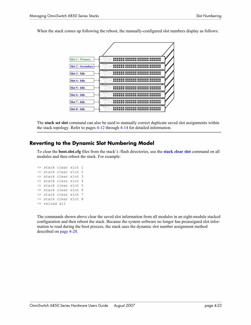
Managing OmniSwitch 6850 Series Stacks Slot Numbering
When the stack comes up following the reboot, the manually-configured slot numbers display as follows:
The stack set slot command can also be used to manually correct duplicate saved slot assignments within the stack topology. Refer to pages 4-12 through 4-14 for detailed information.
Reverting to the Dynamic Slot Numbering ModelTo clear the boot.slot.cfg files from the stack’s /flash directories, use the stack clear slot command on all modules and then reboot the stack. For example:
-> stack clear slot 1-> stack clear slot 2-> stack clear slot 3-> stack clear slot 4-> stack clear slot 5-> stack clear slot 6-> stack clear slot 7-> stack clear slot 8-> reload all
The commands shown above clear the saved slot information from all modules in an eight-module stacked configuration and then reboot the stack. Because the system software no longer has preassigned slot infor-mation to read during the boot process, the stack uses the dynamic slot number assignment method described on page 4-20.
Slot 4 - Idle
Slot 5 - Idle
Slot 6 - Idle
Slot 7 - Idle
Slot 8 - Idle
Slot 1 - Primary
Slot 2 - Secondary
Slot 3 - Idle
OmniSwitch 6850 Series Hardware Users Guide August 2007 page 4-23
Hot-Swapping Modules In a Stack Managing OmniSwitch 6850 Series Stacks
Hot-Swapping Modules In a StackAs with chassis-based switches, such as the OmniSwitch 9700/9800, NI modules within an OmniSwitch 6850 Series virtual chassis are hot-swappable. NI modules are essentially those modules operating in the stack in idle mode. These modules can be removed from, or added to, an existing stack without disrupting other modules in the stack.
Removing Switches from an Existing StackWhen removing switches from an existing stack, observe the following important guidelines:
• Do not attempt to hot-swap modules operating in primary or secondary management roles
• Be sure the stacking cables and stacking cable redundancy are not disrupted
Hot-swapping is intended for switches in idle and, if applicable, pass-through status only. Removing primary or secondary management modules from a stack will trigger a failover sequence, i.e., one or more additional modules within the stack must reload in order to reassign the management roles. Whenever possible, avoid removing a switch that is operating as a primary or secondary management module.
Also, removing a switch from a stacked configuration can disrupt stack cabling at the rear of the stack. When removing a module, be sure that stacking link integrity, including important stacking cable redun-dancy, is maintained between all remaining modules. For more information on stacking cable connec-tions, refer to page 4-16.
Inserting Switches Into an Existing StackWhen inserting switches into an existing stack, observe the following important guidelines:
• Avoid duplicate saved slot numbers
• Never attempt to operate more than eight switches in a single stack
• Make sure all switches are running the same software version.
Note. Other stackable Alcatel-Lucent products, such as the OmniSwitch 6600 Family switch, cannot be added to an OmniSwitch 6850 Series virtual chassis.
To avoid duplicate slot numbers, simply make sure that any modules being added to an existing stack have been cleared of preassigned slot information. In other words, verify that there is no boot.slot.cfg file present in the /flash directory of any switch being added. When the switch is connected to the existing stack and booted, the system software automatically assigns it a unique slot number. No duplicate slot errors occur.
Note. If it is preferable to add a switch with an existing boot.slot.cfg file to a stack, be sure that the saved slot number of the incoming switch is not already assigned to a switch operating in the stack.
page 4-24 OmniSwitch 6850 Series Hardware Users Guide August 2007

Managing OmniSwitch 6850 Series Stacks Hot-Swapping Modules In a Stack
Merging StacksMerging stacks involves connecting two or more operational stacks and attempting to reboot them as a single virtual chassis. In most cases, errors will result. To merge stacks without causing errors, select one stack that is to remain up and running and then add modules from the other stack(s) by following the steps below:
1 Make sure all switches are running the same software version.
2 Clear the saved slot information from all incoming modules. This will ensure that they are each assigned unique slot numbers when they join the stack.
3 After clearing the saved slot information, power off all incoming modules.
4 Connect the stacking cables for all incoming modules to the existing, operational stack as required. Be sure to provide stacking cable redundancy. For information on stack cabling, refer to page 4-16.
5 Power on all incoming modules.
Note. No more than eight switches can operate in a single stacked configuration at any time.
OmniSwitch 6850 Series Hardware Users Guide August 2007 page 4-25
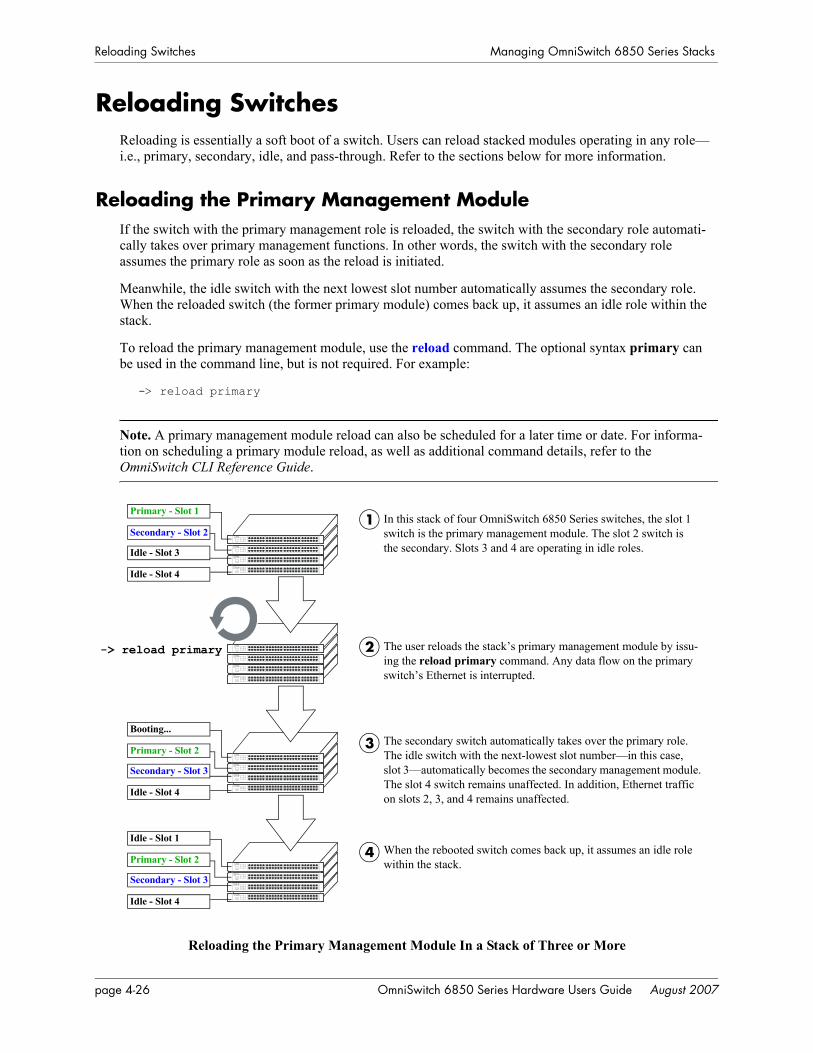
Reloading Switches Managing OmniSwitch 6850 Series Stacks
Reloading SwitchesReloading is essentially a soft boot of a switch. Users can reload stacked modules operating in any role—i.e., primary, secondary, idle, and pass-through. Refer to the sections below for more information.
Reloading the Primary Management ModuleIf the switch with the primary management role is reloaded, the switch with the secondary role automati-cally takes over primary management functions. In other words, the switch with the secondary role assumes the primary role as soon as the reload is initiated.
Meanwhile, the idle switch with the next lowest slot number automatically assumes the secondary role. When the reloaded switch (the former primary module) comes back up, it assumes an idle role within the stack.
To reload the primary management module, use the reload command. The optional syntax primary can be used in the command line, but is not required. For example:
-> reload primary
Note. A primary management module reload can also be scheduled for a later time or date. For informa-tion on scheduling a primary module reload, as well as additional command details, refer to the OmniSwitch CLI Reference Guide.
Reloading the Primary Management Module In a Stack of Three or More
In this stack of four OmniSwitch 6850 Series switches, the slot 1 switch is the primary management module. The slot 2 switch is the secondary. Slots 3 and 4 are operating in idle roles.
The user reloads the stack’s primary management module by issu-ing the reload primary command. Any data flow on the primary switch’s Ethernet is interrupted.
The secondary switch automatically takes over the primary role. The idle switch with the next-lowest slot number—in this case, slot 3—automatically becomes the secondary management module. The slot 4 switch remains unaffected. In addition, Ethernet traffic on slots 2, 3, and 4 remains unaffected.
1
2
3
-> reload primary
Primary - Slot 1
Secondary - Slot 2
Idle - Slot 3
Idle - Slot 4
Booting...
Primary - Slot 2
Secondary - Slot 3
Idle - Slot 4
When the rebooted switch comes back up, it assumes an idle role within the stack.
4Idle - Slot 1
Primary - Slot 2
Secondary - Slot 3
Idle - Slot 4
page 4-26 OmniSwitch 6850 Series Hardware Users Guide August 2007
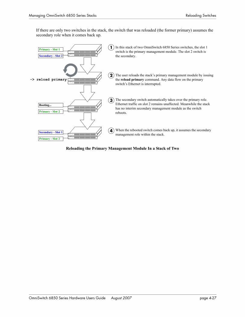
Managing OmniSwitch 6850 Series Stacks Reloading Switches
If there are only two switches in the stack, the switch that was reloaded (the former primary) assumes the secondary role when it comes back up.
Reloading the Primary Management Module In a Stack of Two
In this stack of two OmniSwitch 6850 Series switches, the slot 1 switch is the primary management module. The slot 2 switch is the secondary.
The user reloads the stack’s primary management module by issuing the reload primary command. Any data flow on the primary switch’s Ethernet is interrupted.
The secondary switch automatically takes over the primary role. Ethernet traffic on slot 2 remains unaffected. Meanwhile the stack has no interim secondary management module as the switch reboots.
1
2
3
-> reload primary
Primary - Slot 1
Secondary - Slot 2
When the rebooted switch comes back up, it assumes the secondary management role within the stack.
4
Booting...
Primary - Slot 2
Secondary - Slot 1
Primary - Slot 2
OmniSwitch 6850 Series Hardware Users Guide August 2007 page 4-27
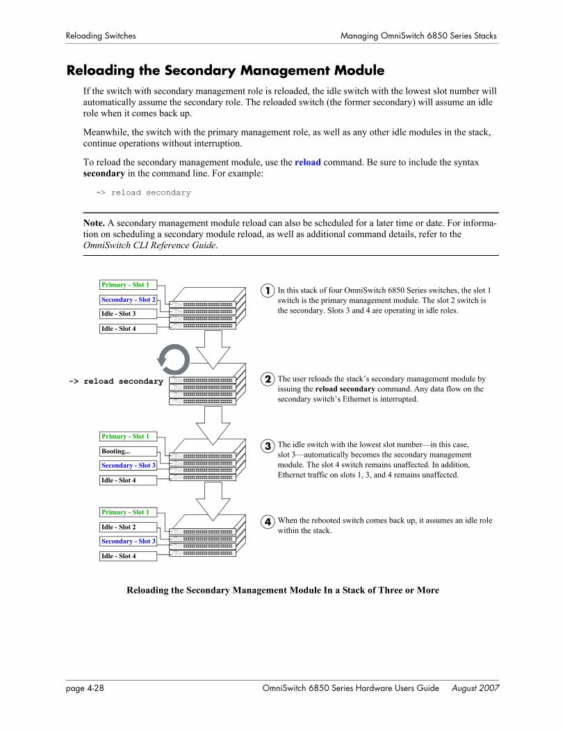
Reloading Switches Managing OmniSwitch 6850 Series Stacks
Reloading the Secondary Management ModuleIf the switch with secondary management role is reloaded, the idle switch with the lowest slot number will automatically assume the secondary role. The reloaded switch (the former secondary) will assume an idle role when it comes back up.
Meanwhile, the switch with the primary management role, as well as any other idle modules in the stack, continue operations without interruption.
To reload the secondary management module, use the reload command. Be sure to include the syntax secondary in the command line. For example:
-> reload secondary
Note. A secondary management module reload can also be scheduled for a later time or date. For informa-tion on scheduling a secondary module reload, as well as additional command details, refer to the OmniSwitch CLI Reference Guide.
Reloading the Secondary Management Module In a Stack of Three or More
In this stack of four OmniSwitch 6850 Series switches, the slot 1 switch is the primary management module. The slot 2 switch is the secondary. Slots 3 and 4 are operating in idle roles.
The user reloads the stack’s secondary management module by issuing the reload secondary command. Any data flow on the secondary switch’s Ethernet is interrupted.
The idle switch with the lowest slot number—in this case, slot 3—automatically becomes the secondary management module. The slot 4 switch remains unaffected. In addition, Ethernet traffic on slots 1, 3, and 4 remains unaffected.
1
2
3
-> reload secondary
Primary - Slot 1
Secondary - Slot 2
Idle - Slot 3
Idle - Slot 4
Primary - Slot 1
Booting...
Secondary - Slot 3
Idle - Slot 4
When the rebooted switch comes back up, it assumes an idle role within the stack.
4Primary - Slot 1
Idle - Slot 2
Secondary - Slot 3
Idle - Slot 4
page 4-28 OmniSwitch 6850 Series Hardware Users Guide August 2007
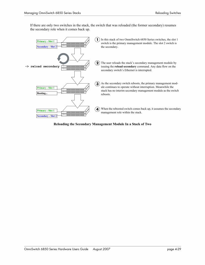
Managing OmniSwitch 6850 Series Stacks Reloading Switches
If there are only two switches in the stack, the switch that was reloaded (the former secondary) resumes the secondary role when it comes back up.
Reloading the Secondary Management Module In a Stack of Two
In this stack of two OmniSwitch 6850 Series switches, the slot 1 switch is the primary management module. The slot 2 switch is the secondary.
The user reloads the stack’s secondary management module by issuing the reload secondary command. Any data flow on the secondary switch’s Ethernet is interrupted.
As the secondary switch reboots, the primary management mod-ule continues to operate without interruption. Meanwhile the stack has no interim secondary management module as the switch reboots.
1
2
3
-> reload secondary
Primary - Slot 1
Secondary - Slot 2
When the rebooted switch comes back up, it assumes the secondarymanagement role within the stack.
4
Primary - Slot 1
Booting...
Primary - Slot 1
Secondary - Slot 2
OmniSwitch 6850 Series Hardware Users Guide August 2007 page 4-29
Reloading Switches Managing OmniSwitch 6850 Series Stacks
Reloading Switches with Idle RolesSimilar to reloading Network Interface (NI) modules on chassis-based switches such as the OmniSwitch 9700/9800, modules operating in idle status within a stack can be reloaded via the CLI.
Note. Any traffic being passed on the module’s Ethernet will be interrupted during the reboot. Other modules within the stack will continue to operate without interruption.
To reset a single module operating in idle mode, use the reload ni command. Be sure to include the slot number of the idle switch in the command line. For example:
-> reload ni 3
Only one idle switch can be reloaded at a time. In order to reload multiple idle switches at once, the entire stack must be reloaded using the reload all command.
After reloading a switch operating in an idle role, the switch resumes idle status when it comes back up, despite its saved slot number. In other words, if an idle switch with a saved slot number of 1 is reloaded, it resumes its previous idle role. Although it has the lowest possible saved slot number, it does not take over the primary management role. In order for this switch to take over the primary role, all switches in the stack must be reloaded.
Note. For more information on reloading all the switches in a stack, refer to page 4-31. For more informa-tion on idle status, refer to page 4-11.
Reloading Switches in Pass-Through ModePass-through mode is a state in which a switch has attempted to join a stack but has been denied primary, secondary, and idle status. Because this is essentially an error state, the pass-through condition must be resolved and any modules operating in pass-through mode must be reloaded.
To reload a module operating in pass-through mode, use the reload pass-through command. Be sure to include the slot number of the pass-through switch in the command line. For example:
-> reload pass-through 1001
Note. Before issuing the reload pass-through command, be sure to resolve any conditions causing the switch to operate in pass-through mode. Otherwise, the switch is likely to come up again in pass-through mode. For detailed information, including steps used to recover from pass-through, refer to page 4-12.
page 4-30 OmniSwitch 6850 Series Hardware Users Guide August 2007
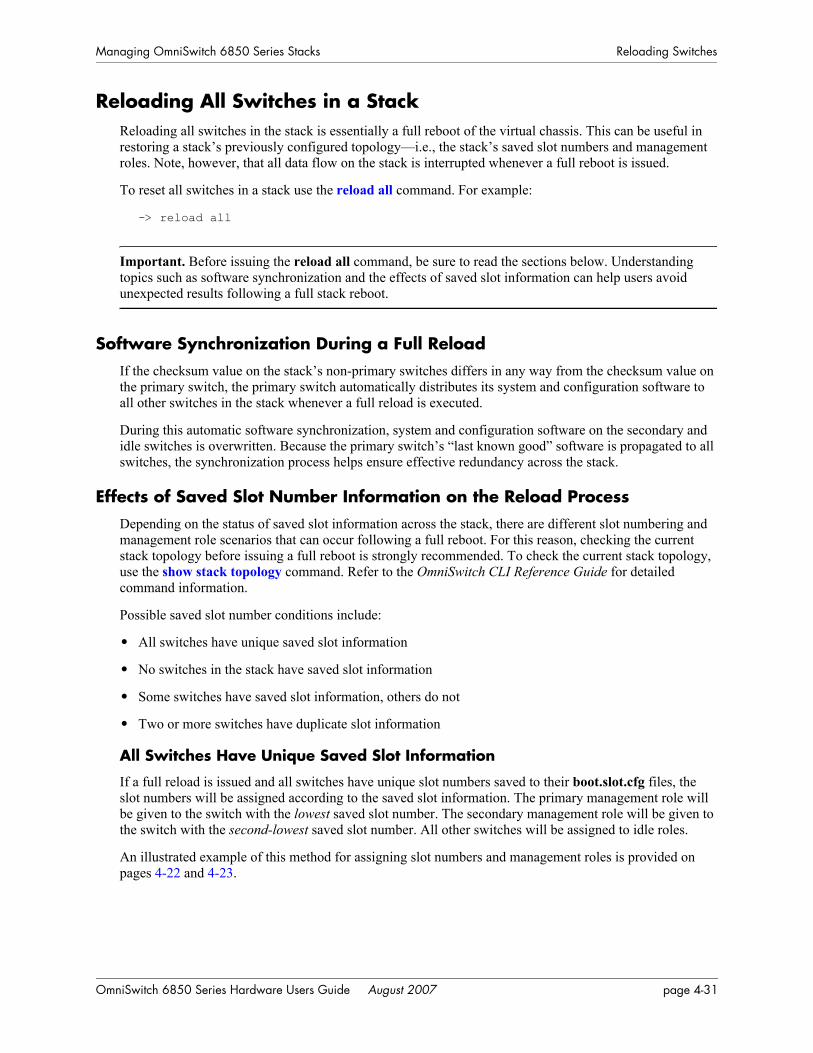
Managing OmniSwitch 6850 Series Stacks Reloading Switches
Reloading All Switches in a StackReloading all switches in the stack is essentially a full reboot of the virtual chassis. This can be useful in restoring a stack’s previously configured topology—i.e., the stack’s saved slot numbers and management roles. Note, however, that all data flow on the stack is interrupted whenever a full reboot is issued.
To reset all switches in a stack use the reload all command. For example:
-> reload all
Important. Before issuing the reload all command, be sure to read the sections below. Understanding topics such as software synchronization and the effects of saved slot information can help users avoid unexpected results following a full stack reboot.
Software Synchronization During a Full ReloadIf the checksum value on the stack’s non-primary switches differs in any way from the checksum value on the primary switch, the primary switch automatically distributes its system and configuration software to all other switches in the stack whenever a full reload is executed.
During this automatic software synchronization, system and configuration software on the secondary and idle switches is overwritten. Because the primary switch’s “last known good” software is propagated to all switches, the synchronization process helps ensure effective redundancy across the stack.
Effects of Saved Slot Number Information on the Reload ProcessDepending on the status of saved slot information across the stack, there are different slot numbering and management role scenarios that can occur following a full reboot. For this reason, checking the current stack topology before issuing a full reboot is strongly recommended. To check the current stack topology, use the show stack topology command. Refer to the OmniSwitch CLI Reference Guide for detailed command information.
Possible saved slot number conditions include:
• All switches have unique saved slot information
• No switches in the stack have saved slot information
• Some switches have saved slot information, others do not
• Two or more switches have duplicate slot information
All Switches Have Unique Saved Slot Information
If a full reload is issued and all switches have unique slot numbers saved to their boot.slot.cfg files, the slot numbers will be assigned according to the saved slot information. The primary management role will be given to the switch with the lowest saved slot number. The secondary management role will be given to the switch with the second-lowest saved slot number. All other switches will be assigned to idle roles.
An illustrated example of this method for assigning slot numbers and management roles is provided on pages 4-22 and 4-23.
OmniSwitch 6850 Series Hardware Users Guide August 2007 page 4-31

Reloading Switches Managing OmniSwitch 6850 Series Stacks
No Switches In the Stack Have Saved Slot Information
If a full reload is issued and no switches in the stack have unique slot numbers, slot numbers will be assigned beginning with the switch with the lowest MAC address. (This can occur if the boot.slot.cfg file has been deleted from each switch’s /flash directory—e.g., by issuing the stack clear slot command for all modules in the stack.)
The switch with the lowest MAC address is assigned slot number 1 and given the primary management role. The switch connected to stacking port A of the primary switch is automatically assigned slot number 2 and given the secondary management role. Stack cabling is then used to determine the dynamic slot numbering of the remaining modules in the stack. The switch immediately adjacent to slot 2 is assigned slot number 3 and given an idle role, etc.
An illustrated example of this method for assigning slot numbers and management roles is provided on pages 4-20 and 4-21.
Some Switches Have Saved Slot Information, Others Do Not
If only some switches in the stack have boot.slot.cfg files in their /flash directories, the system software will first read the contents of these files and then dynamically assigns unique slot numbers to any switches that do not have saved slot information. The primary management role will be given to the switch with the lowest saved slot number. The secondary management role will be given to the switch with the second-lowest saved slot number. All other switches will be assigned to idle roles.
When unique slot numbers are dynamically assigned by the system software, a boot.slot.cfg file is auto-matically generated with the new slot information. Because all switches now have unique saved slot infor-mation, any subsequent reload all commands issued will cause the stack to come up as described in the section, “All Switches Have Unique Saved Slot Information” on page 4-31.
Two or More Switches Have Duplicate Slot Information
If a full stack reboot is issued and the same slot number is found in the boot.slot.cfg file of two or more switches, the switch with the lowest MAC address is allowed to come up and operate normally. Mean-while, any other switches with the duplicate slot number come up in pass-through mode.
The pass-through mode is essentially an error state in which a switch has been denied primary, secondary, and idle roles within the stack. When a switch is in pass-through mode, its Ethernet are brought down and cannot pass traffic. It is for this reason that users should always check the current saved slot number for each switch before issuing the reload all command. To check the current saved slot information across the stack, use the show stack topology command. For detailed information on pass-through mode, refer to “Pass-Through Mode” on page 4-12.
page 4-32 OmniSwitch 6850 Series Hardware Users Guide August 2007

Managing OmniSwitch 6850 Series Stacks Reloading Switches
Avoiding Split StacksThe term “splitting” a stack refers to the creation of isolated modules within the virtual chassis. A split stack can result from the following conditions:
• Two or more non-adjacent switches are reloaded simultaneously
• The stack is reloaded without a redundant stacking cable connection
The sections below offer simple guidelines for avoiding splitting the stack during the reload process.
Do Not Reload Non-Adjacent Switches Simultaneously
If non-adjacent switches in the stack—for example, the top switch in the stack and the third-from-top switch in the stack—are reloaded simultaneously, a problem will occur. The switch between the two non-adjacent switches will become isolated and the virtual chassis will be effectively split.
To avoid splitting the stack, do not reload the two non-adjacent switches simultaneously. Instead, simply reload the top switch first, then reload the third-from-top switch, or vice-versa.
Be Sure a Redundant Stacking Cable is Installed at All Times
Another important guideline for avoiding split stacks involves the redundant stacking cable. In order to avoid isolated modules within the virtual chassis, simply make sure that a redundant stacking cable connection exists between the top-most and bottom-most switches at all times.
For more information on the redundant stacking cable connection, refer to page 4-17.
OmniSwitch 6850 Series Hardware Users Guide August 2007 page 4-33
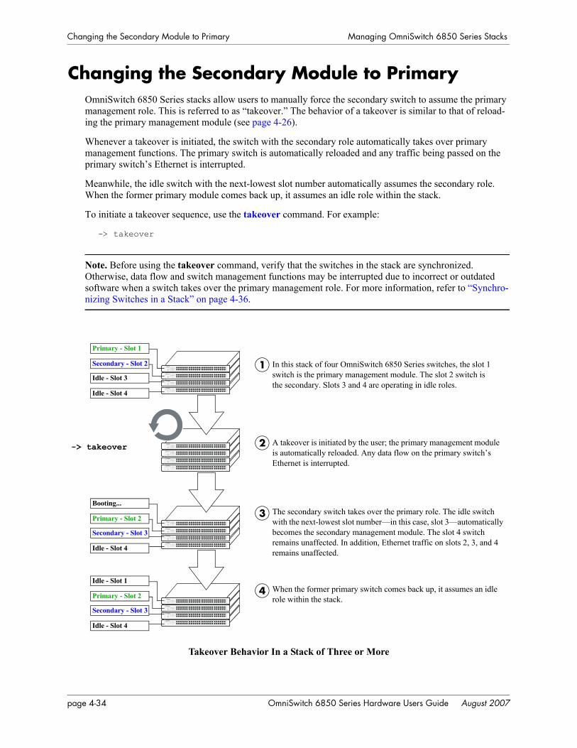
Changing the Secondary Module to Primary Managing OmniSwitch 6850 Series Stacks
Changing the Secondary Module to PrimaryOmniSwitch 6850 Series stacks allow users to manually force the secondary switch to assume the primary management role. This is referred to as “takeover.” The behavior of a takeover is similar to that of reload-ing the primary management module (see page 4-26).
Whenever a takeover is initiated, the switch with the secondary role automatically takes over primary management functions. The primary switch is automatically reloaded and any traffic being passed on the primary switch’s Ethernet is interrupted.
Meanwhile, the idle switch with the next-lowest slot number automatically assumes the secondary role. When the former primary module comes back up, it assumes an idle role within the stack.
To initiate a takeover sequence, use the takeover command. For example:
-> takeover
Note. Before using the takeover command, verify that the switches in the stack are synchronized. Otherwise, data flow and switch management functions may be interrupted due to incorrect or outdated software when a switch takes over the primary management role. For more information, refer to “Synchro-nizing Switches in a Stack” on page 4-36.
Takeover Behavior In a Stack of Three or More
In this stack of four OmniSwitch 6850 Series switches, the slot 1 switch is the primary management module. The slot 2 switch is the secondary. Slots 3 and 4 are operating in idle roles.
A takeover is initiated by the user; the primary management module is automatically reloaded. Any data flow on the primary switch’s Ethernet is interrupted.
The secondary switch takes over the primary role. The idle switch with the next-lowest slot number—in this case, slot 3—automatically becomes the secondary management module. The slot 4 switch remains unaffected. In addition, Ethernet traffic on slots 2, 3, and 4 remains unaffected.
1
2
3
-> takeover
Primary - Slot 1
Secondary - Slot 2
Idle - Slot 3
Idle - Slot 4
Booting...
Primary - Slot 2
Secondary - Slot 3
Idle - Slot 4
When the former primary switch comes back up, it assumes an idle role within the stack.
4Idle - Slot 1
Primary - Slot 2
Secondary - Slot 3
Idle - Slot 4
page 4-34 OmniSwitch 6850 Series Hardware Users Guide August 2007
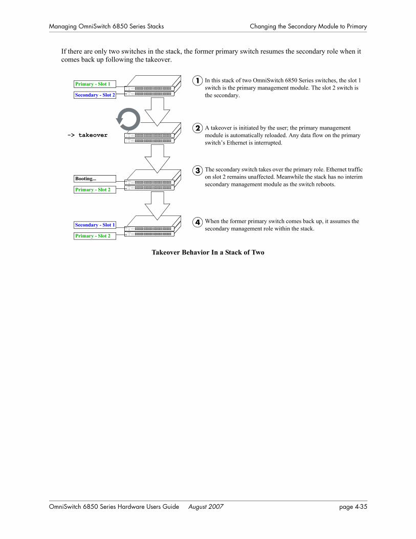
Managing OmniSwitch 6850 Series Stacks Changing the Secondary Module to Primary
If there are only two switches in the stack, the former primary switch resumes the secondary role when it comes back up following the takeover.
Takeover Behavior In a Stack of Two
In this stack of two OmniSwitch 6850 Series switches, the slot 1 switch is the primary management module. The slot 2 switch is the secondary.
A takeover is initiated by the user; the primary management module is automatically reloaded. Any data flow on the primary switch’s Ethernet is interrupted.
The secondary switch takes over the primary role. Ethernet traffic on slot 2 remains unaffected. Meanwhile the stack has no interim secondary management module as the switch reboots.
1
2
3
-> takeover
Primary - Slot 1
Secondary - Slot 2
When the former primary switch comes back up, it assumes the secondary management role within the stack.
4
Booting...
Primary - Slot 2
Secondary - Slot 1
Primary - Slot 2
OmniSwitch 6850 Series Hardware Users Guide August 2007 page 4-35
Synchronizing Switches in a Stack Managing OmniSwitch 6850 Series Stacks
Synchronizing Switches in a StackManagement module synchronization refers to the process of copying all files in the /flash/working and /flash/certified directories of the primary management module to the /flash/working and /flash/certified directories of all the other switches in the stack. The system and configuration software on the non-primary switches—i.e., the secondary management module and any modules operating in idle—is over-written.
The synchronization process ensures that the contents of these directories match exactly for all switches across the stack. This can be especially useful after new software has been loaded to the primary manage-ment module. Further, synchronization prevents any switch from assuming a management role within the stack with incorrect or outdated software or configuration files. Because the primary switch’s “last known good” software is propagated to all switches, the synchronization process helps ensure effective redun-dancy across the stack.
In order to maintain effective management module redundancy, switches in the stack must be synchro-nized at all times. To determine whether a stack is in need of synchronization, use the show running-directory command. For example:
-> show running-configuration
CONFIGURATION STATUS Running CMM : PRIMARY, CMM Mode : DUAL CMMs, Current CMM Slot : 1, Running configuration : WORKING, Certify/Restore Status : CERTIFY NEEDEDSYNCHRONIZATION STATUS Flash Between CMMs : NOT SYNCHRONIZED, Running Configuration : NOT AVAILABLE, Stacks Reload on Takeover: PRIMARY ONLY
This example shows a switch on which the /flash directories between the management modules are not synchronized. To manually synchronize all switches in the stack, enter the following command:
-> copy working certified flash-syncro
When the synchronization process is initiated, modules within the stack continue to operate without inter-ruption and data flow across the stack is unaffected.
Automatic Synchronization During a Full ReloadIf the checksum value on the stack’s non-primary switches differs in any way from the checksum value on the primary switch, the primary switch automatically distributes its system and configuration software to all other switches in the stack whenever a full reload is executed.
For more information on initiating a full reload, see “Reloading All Switches in a Stack” on page 4-31.
Note. For more information on management module synchronization and managing the /flash/working and /flash/certified directories, refer to the “Managing CMM Directory Content” chapter in the Switch Management Guide.
page 4-36 OmniSwitch 6850 Series Hardware Users Guide August 2007
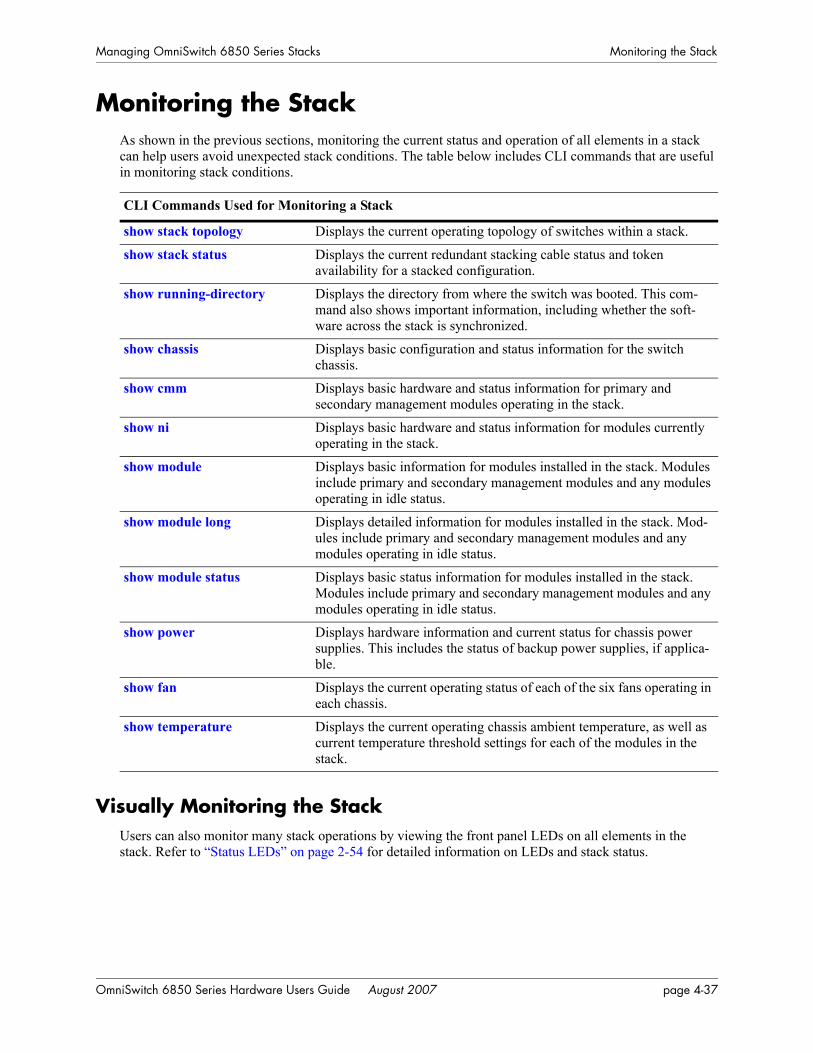
Managing OmniSwitch 6850 Series Stacks Monitoring the Stack
Monitoring the StackAs shown in the previous sections, monitoring the current status and operation of all elements in a stack can help users avoid unexpected stack conditions. The table below includes CLI commands that are useful in monitoring stack conditions.
Visually Monitoring the StackUsers can also monitor many stack operations by viewing the front panel LEDs on all elements in the stack. Refer to “Status LEDs” on page 2-54 for detailed information on LEDs and stack status.
CLI Commands Used for Monitoring a Stack
show stack topology Displays the current operating topology of switches within a stack.
show stack status Displays the current redundant stacking cable status and token availability for a stacked configuration.
show running-directory Displays the directory from where the switch was booted. This com-mand also shows important information, including whether the soft-ware across the stack is synchronized.
show chassis Displays basic configuration and status information for the switch chassis.
show cmm Displays basic hardware and status information for primary and secondary management modules operating in the stack.
show ni Displays basic hardware and status information for modules currently operating in the stack.
show module Displays basic information for modules installed in the stack. Modules include primary and secondary management modules and any modules operating in idle status.
show module long Displays detailed information for modules installed in the stack. Mod-ules include primary and secondary management modules and any modules operating in idle status.
show module status Displays basic status information for modules installed in the stack. Modules include primary and secondary management modules and any modules operating in idle status.
show power Displays hardware information and current status for chassis power supplies. This includes the status of backup power supplies, if applica-ble.
show fan Displays the current operating status of each of the six fans operating in each chassis.
show temperature Displays the current operating chassis ambient temperature, as well as current temperature threshold settings for each of the modules in the stack.
OmniSwitch 6850 Series Hardware Users Guide August 2007 page 4-37
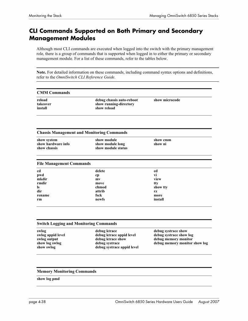
Monitoring the Stack Managing OmniSwitch 6850 Series Stacks
CLI Commands Supported on Both Primary and Secondary Management Modules
Although most CLI commands are executed when logged into the switch with the primary management role, there is a group of commands that is supported when logged in to either the primary or secondary management module. For a list of these commands, refer to the tables below.
Note. For detailed information on these commands, including command syntax options and definitions, refer to the OmniSwitch CLI Reference Guide.
CMM Commands
reloadtakeoverinstall
debug chassis auto-rebootshow running-directoryshow reload
show microcode
Chassis Management and Monitoring Commands
show systemshow hardware infoshow chassis
show moduleshow module longshow module status
show cmmshow ni
File Management Commands
cdpwdmkdirrmdirlsdirrenamerm
deletecpmvmovechmodattribfscknewfs
edviviewttyshow ttyrzmoreinstall
Switch Logging and Monitoring Commands
swlogswlog appid levelswlog outputshow log swlogshow swlog
debug ktracedebug ktrace appid leveldebug ktrace showdebug systracedebug systrace appid level
debug systrace showdebug systrace show logdebug memory monitordebug memory monitor show log
Memory Monitoring Commands
show log pmd
page 4-38 OmniSwitch 6850 Series Hardware Users Guide August 2007

A Regulatory Complianceand Safety Information
This appendix provides information on regulatory agency compliance and safety for the OmniSwitch 6850 Series.
Declaration of Conformity: CE MarkThis equipment is in compliance with the essential requirements and other provisions of Directive 73/23/EEC and 89/336/EEC as amended by Directive 93/68/EEC.
Français: Ce matériel est conformément aux conditions essentielles et à d'autres dispositions de 73/23/EEC et de 89/336/EEC directifs comme modifié par Directive 93/68/EEC.
Deutsch: Konformitätserklärung: CE KennzeichnungDiese Anlage ist gemäß den wesentlichen Anforderungen und anderen Bestimmungen richtungweisenden 73/23/EEC und des 89/336/EEC, wie von Directive 93/68/EEC geändert.
Español: Este directivo equipo está en conformidad con los requisitos esenciales y otras provisiones 73/23/EEC y 89/336/EEC según la enmienda prevista por Directive 93/68/EEC.
Waste Electrical and Electronic Equipment (WEEE) StatementThe product at end of life is subject to separate collection and treatment in the EU Member States, Norway and Switzerland and therefore marked with the symbol:
Treatment applied at end of life of the product in these countries shall comply with the applicable national laws implementing directive 2002/96EC on waste electrical and electronic equipment (WEEE).
OmniSwitch 6850 Series Hardware Users Guide August 2007 page A-1

China RoHS: Hazardous Substance Table Regulatory Compliance and Safety Information
China RoHS: Hazardous Substance Table
产品说明书附件 SUPPLEMENT TO PRODUCT INSTRUCTIONS
有毒有害物质或元素 (Hazardous Substance) 部件名称
(Parts) 铅
(Pb) 汞
(Hg) 镉
(Cd) 六价铬
(Cr6+)
多溴联苯
(PBB) 多溴二苯醚
(PBDE) 电路模块
(Circuit Modules) × ○ ○ ○ ○ ○
电缆及电缆组件
(Cables & Cable Assemblies) × ○ ○ ○ ○ ○
金属部件
(Metal Parts) × ○ ○ ○ ○ ○
塑料和聚合物部件
(Plastic and Polymeric parts) ○ ○ ○ ○ ○ ○
对于交付时集成了电池的电子信息产品 For electronic information products delivered with integrated functional batteries:
电池
(Batteries) ○ ○ ○ ○ ○ ○
○: 表示该有毒有害物质在该部件所有均质材料中的含量均在 SJ/T11363-2006 标准规定的限量要求以下。
Indicates that the concentration of the hazardous substance in all homogeneous materials in the parts is below the relevant threshold of the SJ/T11363-2006 standard.
×: 表示该有毒有害物质至少在该部件的某一均质材料中的含量超出SJ/T11363-2006标准规定的限量要求。
Indicates that the concentration of the hazardous substance of at least one of all homogeneous materials in the parts is above the relevant threshold of the SJ/T11363-2006 standard.
对销售之日的所售产品,本表显示, 阿尔卡特朗讯公司供应链的电子信息产品可能包含这些物质。注意:在所售产
品中可能会也可能不会含有所有所列的部件。
This table shows where these substances may be found in the supply chain of Alcatel-Lucent electronic information products, as of the date of sale of the enclosed product. Note that some of the component
types listed above may or may not be a part of the enclosed product.
这个文件涉及的是在中华人民共和国境内进口或销售的电子信息产品 Include this document with all Electronic Information Products imported
or sold in the People’s Republic of China
除非另外特别的标注,此标志为针对所涉及产品的环保使用期标志. 某些零部件会有
一个不同的环保使用期(例如,电池单元模块)贴在其产品上.
此环保使用期限只适用于产品是在产品手册中所规定的条件下工作. The Environment- Friendly Use Period (EFUP) for all enclosed products and their parts are per the symbol shown here, unless otherwise marked. Certain parts may have a different EFUP (for example, battery modules) and so are marked to reflect such. The Environment- Friendly Use Period is valid only when the product is operated under the conditions defined in the product manual.
50
page A-2 OmniSwitch 6850 Series Hardware Users Guide August 2007
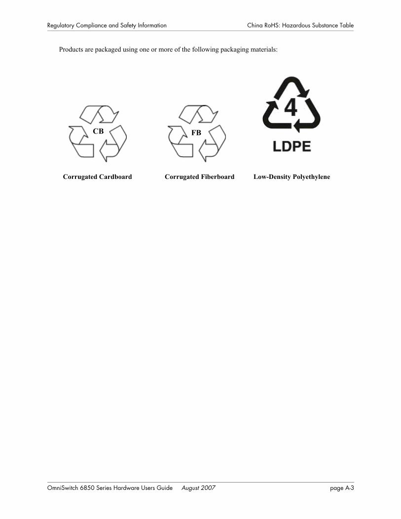
Regulatory Compliance and Safety Information China RoHS: Hazardous Substance Table
Products are packaged using one or more of the following packaging materials:
Corrugated Cardboard Corrugated Fiberboard Low-Density Polyethylene
CB FB
OmniSwitch 6850 Series Hardware Users Guide August 2007 page A-3
Standards Compliance Regulatory Compliance and Safety Information
Standards ComplianceThe product bears the CE mark. In addition it is in compliance with the following other safety and EMC standards:
Safety Standards
• UL 60950• CAN/CSA-C22.2 No. 60950-00• EN 60950• IEC 60950• TS 001• AS/NZS 3260• CB Certification PBR IEC 950
EMC Standards
• FCC Part 15 (CFR 47) Class A• ICES-003 Class A• EN 55022 Class A• CISPR 22 Class A• AS/NZS 3548 Class A• VCCI Class A• EN 55024• EN 50082-1• EN 61000-3-2• EN 61000-3-3• EN 61000-4-2• EN 61000-4-3• EN 61000-4-4• EN 61000-4-5• EN 61000-4-6• EN 61000-4-8• EN 61000-6-2• EN 61000-6-4• ENC 1000-4-11
Note. The OmniSwitch OS6850-U24X is not compliant with EN 61000-6-2 and EN 61000-6-4 standards.
page A-4 OmniSwitch 6850 Series Hardware Users Guide August 2007

Regulatory Compliance and Safety Information Standards Compliance
Safety and Environmental Standards
• ETS 300 019 Storage Class 1.1• ETS 300 019 Transportation Class 2.3• ETS 300 019 Stationary Use Class 3.1
Standalone OmniSwitch 6850 Series switches comply with Class A standards for digital devices per the FCC Part 15, ICES-003, EN 55022, CISPR 22, AS/NZS 3548, and VCCI standards. Modules with copper connectors meet Class A requirements using unshielded (UTP) cables.
Stacks consisting of two to eight OmniSwitch 6850 Series switches comply with Class A requirements.
FCC Class A, Part 15This equipment has been tested and found to comply with the limits for Class A digital device pursuant to Part 15 of the FCC Rules.These limits are designed to provide reasonable protection against harmful inter-ference when the equipment is operated in a commercial environment.This equipment generates, uses, and can radiate radio frequency energy and, if not installed and used in accordance with the instructions in this guide, may cause interference to radio communications.Operation of this equipment in a residential area is likely to cause interference, in which case the user will be required to correct the interference at his own expense.
The user is cautioned that changes and modifications made to the equipment without approval of the manufacturer could void the user’s authority to operate this equipment.It is suggested that the user use only shielded and grounded cables to ensure compliance with FCC Rules.
If this equipment does cause interference to radio or television reception, the user is encouraged to try to correct the interference by one or more of the following measures:
• Reorient the receiving antenna.
• Relocate the equipment with respect to the receiver.
• Move the equipment away from the receiver.
• Plug the equipment into a different outlet so that equipment and receiver are on different branch circuits.
If necessary, the user should consult the dealer or an experienced radio/television technician for additional suggestions.
Canada Class A StatementThis equipment does not exceed Class A limits per radio noise emissions for digital apparatus, set out in the Radio Interference Regulation of the Canadian Department of Communications.
Avis de conformitè aux normes du ministère des Communications du Canada
Cet èquipement ne dèpasse pas les limites de Classe A d íèmission de bruits radioèlectriques pour les appareils numèriques,telles que prescrites par le RÈglement sur le brouillage radioèlectrique ètabli par le ministère des Communications du Canada.
OmniSwitch 6850 Series Hardware Users Guide August 2007 page A-5

Standards Compliance Regulatory Compliance and Safety Information
JATEThis equipment meets the requirements of the Japan Approvals Institute of Telecommunications Equip-ment (JATE).
CISPR22 Class A warningThis is a Class A product. In a domestic environment, this product may cause radio interference. Under such circumstances, the user may be requested to take appropriate countermeasures.
VCCIThis is a Class A product based on the standard of the Voluntary Control Council for Interference by Information Technology Equipment (VCCI). If this equipment is used in a domestic environment, radio disturbance may arise. When such trouble occurs, the user may be required to take corrective actions.
Class A Warning for Taiwan and Other Chinese MarketsThis is a Class A Information Product. When used in a residential environment, it may cause radio frequency interference. Under such circumstances, the user may be requested to take appropriate counter-measure.
page A-6 OmniSwitch 6850 Series Hardware Users Guide August 2007

Regulatory Compliance and Safety Information NEBS GR-1089 Compliance Requirements
NEBS GR-1089 Compliance RequirementsThe following notes and warnings apply to all NEBS compliant platforms:
Grounding requirements: To ground the equipment properly, connect a Panduit Corporation UL listed Lug, P/N: LCD8-10AL to the two threaded holes located on the rear of each chassis and power supply module. All connections should be made using 8AWG copper conductors.
Use Panduit Corporation, P/N: CT-940CH for crimping. (Each Module must have its own grounding conductor.)
(GR-1089 requires treatment of ground connections and painted surfaces as needed during installation.)
All surfaces that are used for intentionally grounding the EUT shall be brought to a bright finish and an anti oxidant solution must be applied to the surfaces being joined.
Non-conductive coatings (such as lacquer and enamel) must be removed from threads and other contact surfaces to assure electrical conductivity.
(Thread forming screws with paint piercing washers may be used for this purpose during installation)
Warning. The intra-building interfaces of this platform, including Gigabit Ethernet, are suitable for connection to intra-building or unexposed wiring or cabling only with shielded and grounded cables at both ends. The intra-building of the equipment must not be metallically connected to interfaces that connect to the OSP or its wiring.
Note. All bare conductors must be coated with an appropriate antioxidant compound before crimp connec-tions are made. All unplated connectors, braided strap, and bus bars are to be brought to a bright finish and then coated with an antioxidant before connecting them.
OmniSwitch 6850 Series Hardware Users Guide August 2007 page A-7

Translated Safety Warnings Regulatory Compliance and Safety Information
Translated Safety WarningsChassis Lifting Warning
Two people are required when lifting the chassis. Due to its weight, lifting the chassis unassisted can cause personal injury. Also be sure to bend your knees and keep your back straight when assisting with the lift-ing of the chassis.
Français: Le châssis doit être soulevé par deux personnes au minimum. Pour éviter tout risque d'accident, maintenez le dos droit et poussez sur vos jambes. Ne soulevez pas l'unité avec votre dos.
Deutsch: SicherheitshinweiseHinweise zur Anhebung des Chassis
Zum Anheben des Chassis werden zwei Personen benötigt. Aufgrund des Gewichts kann das Anheben ohne Unterstützung zu Personenschäden führen. Heben Sie das Chassis aus den Knien und halten Sie den Rücken gerade wenn Sie beim Anheben des Chassis assistieren.
Español: Se requieren dos personas para elevar el chasis. Para evitar lesiones, mantenga su espalda en posición recta y levante con sus piernas, no con su espalda.
Blank Panels WarningBecause they regulate airflow and help protect internal chassis components, blank cover plates should remain installed at empty module slots and power supply bays at all times.
Français: Les caches blancs remplissent trois fonctions importantes: ils évitent tout risque de choc élec-trique à l'intérieur du châssis, ils font barrage aux interférences électromagnétiques susceptibles d'altérer le fonctionnement des autres équipements et ils dirigent le flux d'air de refroidissement dans le châssis. Il est vivement recommandé de vérifier que tous les caches, modules d'alimentation et plaques de protection sont en place avant d'utiliser le système.
Deutsch: Hinweise zu AbdeckungenDie leeren Modulblenden schützen interne Komponenten und leiten den Luftstrom. Deshalb müssen in allen unbelegten Slots die Modulblenden immer installiert bleiben.
Español: Las tapaderas blancas regulan la circulación de aire y ayudan a proteger componentes internos del chasis y siempre deben estar instaladas en las ranuras vacías del chasis y fuentes de alimentación.
Electrical Storm WarningTo avoid a shock hazard, do not connect or disconnect any cables or perform installation, maintenance, or reconfiguration of this product during an electrical storm.
Français: Ne pas travailler sur le système ni brancher ou débrancher les câbles pendant un orage.
Deutsch: Hinweise bei UnwetterUm elektrische Schläge zu vermeiden dürfen während eines Gewitters and diesem Gerät keine Kabel angeschlossen oder gelöst werden, sowie keinerlei Installationen, Wartungen oder Konfigurationen vorgenommen werden.
Español: Para evitar peligro de descargas, no conecte o desconecte ningun cable, ni realice ninguna insta-lación, maintenimiento o reconfiguración de este producto durante una tormenta eléctrica.
page A-8 OmniSwitch 6850 Series Hardware Users Guide August 2007
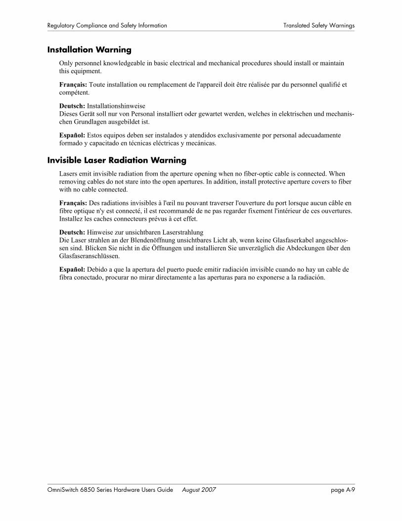
Regulatory Compliance and Safety Information Translated Safety Warnings
Installation WarningOnly personnel knowledgeable in basic electrical and mechanical procedures should install or maintain this equipment.
Français: Toute installation ou remplacement de l'appareil doit être réalisée par du personnel qualifié et compétent.
Deutsch: InstallationshinweiseDieses Gerät soll nur von Personal installiert oder gewartet werden, welches in elektrischen und mechanis-chen Grundlagen ausgebildet ist.
Español: Estos equipos deben ser instalados y atendidos exclusivamente por personal adecuadamente formado y capacitado en técnicas eléctricas y mecánicas.
Invisible Laser Radiation WarningLasers emit invisible radiation from the aperture opening when no fiber-optic cable is connected. When removing cables do not stare into the open apertures. In addition, install protective aperture covers to fiber with no cable connected.
Français: Des radiations invisibles à l'œil nu pouvant traverser l'ouverture du port lorsque aucun câble en fibre optique n'y est connecté, il est recommandé de ne pas regarder fixement l'intérieur de ces ouvertures. Installez les caches connecteurs prévus à cet effet.
Deutsch: Hinweise zur unsichtbaren LaserstrahlungDie Laser strahlen an der Blendenöffnung unsichtbares Licht ab, wenn keine Glasfaserkabel angeschlos-sen sind. Blicken Sie nicht in die Öffnungen und installieren Sie unverzüglich die Abdeckungen über den Glasfaseranschlüssen.
Español: Debido a que la apertura del puerto puede emitir radiación invisible cuando no hay un cable de fibra conectado, procurar no mirar directamente a las aperturas para no exponerse a la radiación.
OmniSwitch 6850 Series Hardware Users Guide August 2007 page A-9

Translated Safety Warnings Regulatory Compliance and Safety Information
Lithium Battery WarningThere is a danger of explosion if the Lithium battery in your chassis is incorrectly replaced. Replace the battery only with the same or equivalent type of battery recommended by the manufacturer. Dispose of used batteries according to the manufacturer’s instructions. The manufacturer’s instructions are as follows: Return the module with the Lithium battery to Alcatel-Lucent. The Lithium battery will be replaced at Alcatel-Lucent’s factory.
Français: Il y a un danger d'explosion si la batterie de lithium dans votre châssis est remplacée avec une autre ne correspondant pas aux préconisations constructeur. Il faut donc renvoyer le module en réparation chez Alcatel-Lucent qui se chargera de remplacer la batterie.
Deutsch: Hinweise zur Lithium BatterieBei falschem Einsetzen der Lithiumbatterie in das Gerät besteht die Gefahr der Explosion. Bitte ersetzen Sie die Batterie nur durch den gleichen bzw. gleichwertigen Typ, empfohlen durch den Hersteller. Benutzte Batterien entsorgen sie bitte wie folgt: Bitte senden Sie das Modul zurück zu Alcatel-Lucent. Dort wird die gebrauchte Batterie ersetzt.
Español: Si substituye las pilas de litio en su chasis, siempre utilice el mismo modelo o el tipo equiva-lente de pila recomendada por el fabricante. Deshágase de las pilas usadas según las instrucciones del fabricante. Devuelva el módulo con la pila de litio a Alcatel-Lucent. La pila de litio será substituida en la fábrica de Alcatel-Lucent.
Dansk: ADVARSEL! Lithiumbatteri--Eksplosionsfare ved fejlagtig handtering. Udskiftning ma kun ske batteri af samme fabrikat og type. Lever det brugte batteri tilbage tilleverandoren.
Operating Voltage WarningTo reduce the risk of electrical shock, keep your hands and fingers out of power supply bays and do not touch the backplane while the switch is operating.
Français: Pour réduire tout risque électrique, gardez vos mains et doigts hors des alimentations et ne touchez pas au fond de panier pendant que le commutateur fonctionne.
Deutsch: Hinweise gegen elektrischen SchlagUm die Gefahr des elektrischen Schlages zu verringern, greifen sie bitte nicht in die Spannungsversor-gung und berühren sie nicht die Rückwandplatine während das Gerät arbeitet.
Español: Para reducir el riesgo de descargas eléctricas, no meta sus manos y dedos dentro del chasis de la fuente de alimentación y no toque componentes internos mientras que el interruptor está conectado.
page A-10 OmniSwitch 6850 Series Hardware Users Guide August 2007

Regulatory Compliance and Safety Information Translated Safety Warnings
Power Disconnection WarningYour switch is equipped with multiple power supplies. To reduce the risk of electrical shock, be sure to disconnect all power connections before servicing or moving the unit.
Français: Il se peut que cette unité soit équipée de plusieurs raccordements d'alimentation. Pour supprimer tout courant électrique de l'unité, tous les cordons d'alimentation doivent être débranchés.
Deutsch: Hinweise zur SpannungsfreischaltungIhr Gerät ist mit mehreren Netzteilen ausgerüstet. Um die Gefahr des elektrischen Schlages zu verringern, stellen sie sicher, daß alle Netzverbindungen getrennt sind bevor das Gerät gewartet oder bewegt wird.
Español: Antes de empezar a trabajar con un sistema, asegurese que el interruptor está cerrado y el cable eléctrico desconectado.
Proper Earthing Requirement WarningTo avoid shock hazard:
• The power cord must be connected to a properly wired and earth receptacle.• Any equipment to which this product will attached must also be connected to properly wired recep-
tacles.• Use 16AWG conductor for ground leads connecting the frame to ground and DC return.• Cleaning and dressing of grounding points during installation is strongly recommended. Also, do
not forget the antioxidant.• To ground the equipment properly, connect a Panduit Corporation UL listed Lug, P/N: LCD8-10A-
L to the two threaded holes located on the rear using 8AWG copper conducters. Use Panduit Corpo-ration, P/N: CT-940CH for crimping.
Français:
Pour éviter tout risque de choc électrique:
• Ne jamais rendre inopérant le conducteur de masse ni utiliser l'équipement sans un conducteur de masse adéquatement installé.
• En cas de doute sur la mise à la masse appropriée disponible, s'adresser à l'organisme responsable de la sécurité électrique ou à un électricien.
Deutsch: Hinweise zur geforderten Erdung des Gerätes
Aus Sicherheitsgründen:
• darf das Netzkabel nur an eine Schutzkontaktsteckdose angeschloossen werden.• dürfen für den Anschluß anderer Geräte, welche mit diesem Gerät verbunden sind, auch nur Schutz-
kontaktsteckdosen verwendet werden.
Español:
Para evitar peligro de descargas:
• Para evitar peligro de descargas asegurese de que el cable de alimentación está conectado a una toma de alimentación adecuadamente cableada y con toma de tierra.
• Cualquier otro equipo a cual se conecte este producto también debe estar conectado a tomas de alimentación adecuadamente cableadas.
OmniSwitch 6850 Series Hardware Users Guide August 2007 page A-11

Translated Safety Warnings Regulatory Compliance and Safety Information
Read Important Safety Information WarningThe Getting Started Guide that accompanied this equipment contains important safety information about which you should be aware when working with hardware components in this system. You should read this guide before installing, using, or servicing this equipment.
Français: Avant de brancher le système sur la source d'alimentation, consultez les directives d'installation disponibles dans le “Getting Started Guide”.
Deutsch: Bitte lesen - SicherheitshinweiseDer Getting Started Guide, welcher diese Anlage beiliegt, enthält wichtige Sicherheitsinformationen, über die sie sich beim Arbeiten mit den Hardwareeinheiten bewußt sein sollten. Sie sollten diese Hinweise lesen, bevor sie installieren, reparieren oder die Anlage verwenden.
Español: La 'Getting Started Guide' que acompañó este equipo contiene información importante de segu-ridad sobre la cual usted debe estar enterado al trabajar con los componentes de dotación física en este sistema. Usted debe leer esta guía antes de instalar, usar o mantener este equipo.
Restricted Access Location WarningThis equipment should be installed in a location that restricts access. A restricted access location is one where access is secure and limited to service personnel who have a special key, or other means of security.
Français: Le matériel doit être installé dans un local avec accès limité ou seules les personnes habilitées peuvent entrer.
Deutsch: Hinweis zu Umgebungen mit beschränktem ZutrittDie Anlage sollte an einem Standort mit beschränktem Zutritt installiert sein. Ein Standort mit beschränk-tem Zutritt stellt sicher, daß dort nur Servicepersonal mit Hilfe eines Schlüssels oder eines anderen Sicher-heitssystems Zugang hat.
Español: Este equipo se debe instalar en un sitio con acceso restrinjido. Un sitio con el acceso restrinjido es uno seguro y con acceso limitado al personal de servicio que tiene una clave especial u otros medios de seguridad.
page A-12 OmniSwitch 6850 Series Hardware Users Guide August 2007

Regulatory Compliance and Safety Information Translated Safety Warnings
Wrist Strap WarningBecause electrostatic discharge (ESD) can damage switch components, you must ground yourself prop-erly before continuing with the hardware installation. For this purpose, Alcatel-Lucent provides a ground-ing wrist strap and a grounding lug located near the top-right of the chassis. For the grounding wrist strap to be effective in eliminating ESD, the power supplies must be installed in the chassis and plugged into grounded AC outlets.
Français: L'électricité statique (ESD) peut endommager les composants du commutateur. Pour cette raison Alcatel-Lucent joint à l'envoi du châssis un bracelet antistatique à brancher sur la prise mise à la terre située en bas à droite du commutateur. Vous devrez mettre ce bracelet avant toute intervention hard-ware.
Deutsch: Hinweise zur ESD (Elektrostatischen Aufladung)Weil elektrostatische Aufladung (ESD) Teile der Anlage beschädigen könnten, müssen sie sich selbst erden, bevor sie mit der Hardware Installation beginnen. Zu diesem Zweck stellt Alcatel-Lucent ein Erdungsarmband und eine Erdungsöse an der oberen rechten Seite des Chassis zur Verfügung. Um eine sichere Erdungsfunktion des Erdungsarmbandes sicherzustellen, müssen die Netzteile installiert und mit dem Schutzleiter des Versorgungsstromkreises verbunden sein.
Español: La descarga electrostática (ESD) puede dañar componentes eletrónicos. Usted debe asegurarse que está en contacto con tierra antes de hacer la instalación del equipo. Con este fin, Alcatel-Lucent proporciona una pulsera de muñeca para conectar al chasis en la toma de tierra situada en la parte superior derecha del chasis. Para que la correa de muñeca sea eficaz en la eliminación de ESD, las fuentes de alimentación deben estar instaladas en el chasis y conectadas a enchufes CA con tierra adecuada.
OmniSwitch 6850 Series Hardware Users Guide August 2007 page A-13

Instrucciones de seguridad en español Regulatory Compliance and Safety Information
Instrucciones de seguridad en españolAdvertencia sobre el levantamiento del chasis
Se requieren dos personas para levantar el chasis. Debido a su peso, la elevación del chasis sin ayuda puede causar daños corporales. También es seguro doblar sus rodillas y guardar su espalda derecho al ayudar a levantar el chasis.
Advertencia de las tapaderas en blancoPorque regulan la circulación de aire y ayudan a proteger componentes internos del chasis, las tapaderas en blanco deben seguir instaladas en las ranuras vacías del módulo y la fuente de alimentación siempre.
Advertencia en caso de tormenta eléctricaPara evitar peligro de descargas, no conecte o desconecte ningun cable, ni realice ninguna instalación, maintenimiento o reconfiguratión de este producto durante una tormenta eléctrica.
Advertencia de instalaciónSolamente el personal bien informado en procedimientos eléctricos y mecánicos básicos debe instalar o mantener este equipo.
Advertencia de radiación láser invisibleLos lasers emiten radiación invisible de la apertura abierta cuando no se conecta ningún cable de fibra óptica. Al quitar los cables no mire fijamente en las aberturas abiertas. Además, instale las cubiertas protectoras de la abertura a las salidas de la fibra sin el cable conectado.
Advertencia de la batería de litioHay un peligro de la explosión si la batería del litio en su chasis se substituye incorrectamente. Substituya la batería solamente por el mismo o el equivalente de tipo de batería recomendado por el fabricante. Deseche las baterías usadas según las instrucciones del fabricante. Las instrucciones del fabricante son como sigue: Devuelva el módulo con la batería del litio a Alcatel-Lucent. La batería del litio será substitu-ida en la fábrica de Alcatel-Lucent.
Advertencia sobre la tensión de operaciónPara reducir el riesgo del choque eléctrico, matenga sus manos y dedos fuera de la fuente de alimentación y no toque la placa madre mientras que el interruptor está funcionando.
Advertencia sobre la desconexión de la fuenteSu interruptor esta equipado por fuentes de alimentación múltiples. Para reducir el riesgo de choque eléc-trico, asegúrese desconectar todas las conexiones de alimentación antes de mantener o de mover la unidad.
page A-14 OmniSwitch 6850 Series Hardware Users Guide August 2007
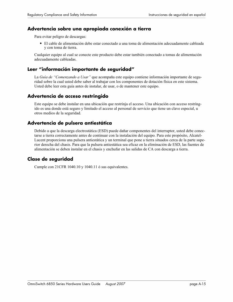
Regulatory Compliance and Safety Information Instrucciones de seguridad en español
Advertencia sobre una apropiada conexión a tierraPara evitar peligro de descargas:
• El cable de alimentación debe estar conectado a una toma de alimentación adecuadamente cableada y con toma de tierra.
Cualquier equipo al cual se conecte este producto debe estar también conectado a tomas de alimentación adecuadamente cableadas.
Leer “información importante de seguridad”La Guía de “Comenzando a Usar” que acompaña este equipo contiene información importante de segu-ridad sobre la cual usted debe saber al trabajar con los componentes de dotación física en este sistema. Usted debe leer esta guía antes de instalar, de usar, o de mantener este equipo.
Advertencia de acceso restringidoEste equipo se debe instalar en una ubicación que restrinja el acceso. Una ubicación con acceso restring-ido es una donde está seguro y limitado el acceso al personal de servicio que tiene un clave especial, u otros medios de la seguridad.
Advertencia de pulsera antiestáticaDebido a que la descarga electrostática (ESD) puede dañar componentes del interruptor, usted debe conec-tarse a tierra correctamente antes de continuar con la instalación del equipo. Para este propósito, Alcatel-Lucent proporciona una pulsera antiestática y un terminal que pone a tierra situados cerca de la parte supe-rior derecha del chasis. Para que la pulsera antiestática sea eficaz en la eliminación de ESD, las fuentes de alimentación se deben instalar en el chasis y enchufar en las salidas de CA con descarga a tierra.
Clase de seguridadCumple con 21CFR 1040.10 y 1040.11 ó sus equivalentes.
OmniSwitch 6850 Series Hardware Users Guide August 2007 page A-15

Instrucciones de seguridad en español Regulatory Compliance and Safety Information
page A-16 OmniSwitch 6850 Series Hardware Users Guide August 2007

Index
Numerics10/100/1000 LEDs 2-55100/1000 SFP LEDs 2-5510000 XFP 1 LEDs 2-5510000 XFP 2 LEDs 2-55
Aapplication examples
OmniSwitch 6850 Series 1-5availability 1-3
hardware monitoring 1-4, 4-37hot swapping 1-4software rollback 1-3
Bblank cover panels 2-59boot serialbaudrate command 2-69boot serialparity command 2-69boot serialtopbits command 2-70boot serialwordsize command 2-69boot.params command 2-70
Cchassis
airflow 2-57, 2-58booting 2-66installation options 2-60installing 2-57monitoring 2-87OS6850-24 front panel 2-23OS6850-24L front panel 2-4OS6850-24X front panel 2-31OS6850-48 front panel 2-27OS6850-48L front panel 2-8OS6850-48X front panel 2-35OS6850-P24 front panel 2-38OS6850-P24L front panel 2-11OS6850-P24X front panel 2-46OS6850-P48 front panel 2-42OS6850-P48L front panel 2-15OS6850-P48X front panel 2-50OS6850-U24X front panel 2-19rack-mounting 2-61rear panel 2-56tabletop 2-60
chassis typesOS6850-24 2-23OS6850-24L 2-4OS6850-24X 2-31
OS6850-48 2-27OS6850-48L 2-8OS6850-48X 2-35OS6850-P24 2-38OS6850-P24L 2-11OS6850-P24X 2-46OS6850-P48 2-42OS6850-P48L 2-15OS6850-P48X 2-50OS6850-U24X 2-19
CLI commandssupported on secondary switch 4-38
commit file command 2-70commit system command 2-70console port 2-69, 2-72
default settings 2-69modifying default settings 2-69
Ddefaults
PoE 3-5
Eexit command 2-70
Hhardware monitoring 1-4, 2-87, 4-37
automatic 1-4LEDs 1-4, 2-67, 2-89user-driven 1-4
hot swapping 1-4, 4-24modules in a stack 4-24
Iidle modules 4-11
reloading 4-30image rollback
see software rollbackInline Power
see PoE
Llanpower capacitor-detection command 3-8lanpower maxpower command 3-7lanpower power command 3-6lanpower priority command 3-7lanpower priority-disconnect command 3-9lanpower start command 3-5lanpower stop command 3-5LEDs
see hardware monitoring
Mmanagement roles
changing the secondary to primary 4-34
OmniSwitch 6850 Series Hardware Users Guide August 2007 Index-1

Index
commands supported on secondary 4-38reloading a stack 4-31synchronizing primary and secondary 4-36
modify boot parameters command 2-69
OOmniSwitch 6850 Series
application examples 1-5OmniSwitch 6850-24 2-23
technical specifications 2-25OmniSwitch 6850-24L
technical specifications 2-6OmniSwitch 6850-24X
technical specifications 2-33OmniSwitch 6850-48
technical specifications 2-29OmniSwitch 6850-48L
technical specifications 2-10OmniSwitch 6850-48X
technical specifications 2-37OmniSwitch 6850-P24
technical specifications 2-40OmniSwitch 6850-P24L
technical specifications 2-13OmniSwitch 6850-P24X
technical specifications 2-48OmniSwitch 6850-P48
technical specifications 2-44OmniSwitch 6850-P48L
technical specifications 2-17OmniSwitch 6850-P48X
technical specifications 2-52OmniSwitch 6850-U24X
technical specifications 2-21OS6850-24
see OmniSwitch 6850-24OS6850-24L
see OmniSwitch 6850-24LOS6850-24X
see OmniSwitch 6850-24XOS6850-48
see OmniSwitch 6850-48OS6850-48L
see OmniSwitch 6850-48LOS6850-48X
see OmniSwitch 6850-48XOS6850-P24
see OmniSwitch 6850-P24OS6850-P24L
see OmniSwitch 6850-P24LOS6850-P48
see OmniSwitch 6850-P48OS6850-P48L
see OmniSwitch 6850-P48LOS6850-P48X
see OmniSwitch 6850-P48XOS6850-U24X
see OmniSwitch 6850-U24X
Ppass-through modules 4-12
reloading 4-30pinouts 2-71PoE 3-1
defaults 3-5monitoring 3-4, 3-12priority disconnect 3-9specifications 3-3
PoE Power Shelfmonitoring 3-4
power cordspecifications 2-68
power cords 2-68Power on LAN
see PoEPower over Ethernet
see PoEPower over LAN
see PoEpower supplies 2-73
PS-126W AC power supply 2-78PS-360W AC power supply 2-77PS-510W AC power supply 2-76
power supply shelf 2-75primary management module 4-3
dynamic selection 4-6reloading 4-26
Rreload all command 4-30reload command 4-26reload ni command 4-30reload pass-through command 4-30
Ssecondary management module 4-3
dynamic selection 4-9reloading 4-28
show command 2-70show chassis command 2-87, 4-37show cmm command 2-88, 4-37show fan command 2-88, 4-37show lanpower command 3-12show module command 2-88, 4-19show module long command 2-88, 4-37show module status command 2-88, 4-37show ni command 2-88, 4-19show power command 2-86, 4-37show stack status command 4-18show stack topology command 4-12show temperature command 2-87, 4-37slot numbering 4-19software rollback 1-3software synchronization 4-36specifications
PoE 3-3
Index-2 OmniSwitch 6850 Series Hardware Users Guide August 2007

Index
power cord 2-68stack clear slot command 4-23stack set slot command 4-13stacks 4-1, 4-38
booting 2-67cabling 2-63, 4-16idle modules 4-11management roles 4-3merging 4-25monitoring 4-37pass-through modules 4-12rack-mounting 2-63reloading 4-26, 4-31setup 2-63
statusLEDs 2-54
Ttakeover command 4-34technical specifications
console port 2-69, 2-72OmniSwitch 6850-24 2-25OmniSwitch 6850-24L 2-6OmniSwitch 6850-24X 2-33OmniSwitch 6850-48 2-29OmniSwitch 6850-48L 2-10OmniSwitch 6850-48X 2-37OmniSwitch 6850-P24 2-40OmniSwitch 6850-P24L 2-13OmniSwitch 6850-P24X 2-48OmniSwitch 6850-P48 2-44OmniSwitch 6850-P48L 2-17OmniSwitch 6850-P48X 2-52OmniSwitch 6850-U24X 2-21pinouts 2-71
OmniSwitch 6850 Series Hardware Users Guide August 2007 Index-3

Index
Index-4 OmniSwitch 6850 Series Hardware Users Guide August 2007