OLM-200 Series Manual - Precision Rated...
32
OLM-200 Series Manual Optical Loss Test Set (OLTS) Copyright © 2014 Precision Rated Optics. All rights reserved. OLM-201 A OLM-201 B OLM-202 A OLM-202 B Version 6.30.14
Transcript of OLM-200 Series Manual - Precision Rated...

OLM-200 Series ManualOptical Loss Test Set (OLTS)
Copyright © 2014 Precision Rated Optics. All rights reserved.
OLM-201 AOLM-201 BOLM-202 AOLM-202 B
Version 6.30.14

Tel: (888) 545-1254 • Fax: (415) 358-4602 • Email: [email protected]
1. Introduction1.1 General Description1.2 Main Features1.3 Typical Applications
3
2. Safety Information 53. Preparing for operation
3.1 Unpacking the Device3.2 The Rechargeable Batteries3.3 AC/DC Adapter/Charger Operation
6
4. Getting Started4.1 The Display and Control Panel4.2 USB Interface4.3 Turning the Device on and off4.4 Activating the “Automatic-Shutdown” Feature4.5 Turning on and off the LCD Backlighting
7
5. Operating the Power Meter5.1 Operating in “Testing” Mode5.2 Operating in “Reference” Mode5.3 Operating in “Data Storage” Mode
10
6. Operating the Light Source.6.1 Switching Wavelengths on the Light Source Module6.2 Switching Between Modulated Wavelength and Constant Wavelength While in Light Source Mode6.3 Switching on/off the “Auto-Recognition” mode of the Light Source and Power Meter
19
7. Operating the OLM-200 Series “Data Manager” Software7.1 “Data Manager” Software Requirements7.2 Installing “Data Manager” Software and Driver on Windows7.3 Starting the Software7.4 Software Operation7.5 Uninstalling the Software
22
8. Basic Maintenance 299. Troubleshooting 2910. Warranty Information 29
Contents
The information contained in this manual is believed to be accurate and reliable at the time of its creation. However, no responsibility is assumed by Precision Rated Optics for its use, nor for any infringements of patents or other rights of third parties that may result from its use. No license is implied or specified under any patent rights of Precision Rated Optics.
* Information contained in this manual is subject to change without notice.

Tel: (888) 545-1254 • Fax: (415) 358-4602 • Email: [email protected] 3
1.1 General Description
The OLM-200 Series Optical Loss Test Set (OLTS) combines a Power Meter and a either a two or three-wavelength Light Source, for optical fiber network installation and maintenance. With its large data storage capacity, it’s very convenient for field testing and transferring test results to a PC, through the USB interface.
1.2 Main Features● Either two or three wavelengths (1310nm, 1490nm and 1550nm)
combined in one port
● Stable Light Source at -5dBm
● Constant Wave (CW) or modulated: 270Hz, 1KHz, 2KHz output
● “Auto Wavelength Recognition” when two OLMs are used together in “TWIN” mode
● Optical Power Meter displays linearity and logarithmic optical power values
● Storage of 999 test results from Optical Power Meter mode
● Backlit screen
● Rechargeable batteries
● LCD display
● “Auto -Off” at low voltage
● “Auto-Off” after 10-min of no operation (default - can be turned off)
● Battery-level display
● “Auto-Off” during charging
1.3 Typical Applications● Optical-loss testing
● Component / Device insertion-loss testing (dB)
● “Tone” fiber identification with 270 Hz, 1 KHz and 2 KHz signals
● Fiber installation and maintenance applications
● FTTx: testing of Passive Optical Networks (PON).
1. Introduction

Tel: (888) 545-1254 • Fax: (415) 358-4602 • Email: [email protected]
SPECIFICATIONS
Item / Model No. OLM-200 Series01A / OLM-200 Series01B
OLM-200 Series02A / OLM-200 Series02B
Light Source
Output Wavelength (nm) 1310/1550 1310/1490/1550
Connector Interchangeable FC/SC/ST for PC
Modulation Frequencies (Hz) 270/1K/2K
Output Power (dBm) -5dBm ± 0.5
Stability Long-Term (8h) (dB) ± 0.1@1310/1550nm; ± 0.2@1490nm
Stability Short-Term (15min) (dB) ± 0.05@1310/1550nm ; ± 0.1@1490nm
Wavelength Recognizing Code Yes
Power Meter
Measuring Range (dBm) (A) -70 ~ +10 / (B) -50 ~ +26
Calibrated Wavelength 850/1300/1310/1490/1550/1625 (nm)
Connector Interchangeable FC, SC, ST for PC/APC
Data Storage (items) 999
Ref. Value Yes
Display Devices dB / dBm / mW / uW
Display Precision (dB) 0.01
Accuracy (nW) ± 5% ± 1
Wavelength Recognition 1310/1490/1550 (Input Power > -40dBm)
Tone Detection 270 Hz / 1KHz / 2KHz (Input Power > -40dBm)
General Specification
Auto Power Off Yes
Power Supply 2000mAh NiMH 1.2V, (x2), AC/DC Adaptor
PC Interface USB
Battery Life > 100 Hours (Light Off)
Operating Temperature 14º F ~ 122º F (-10º C ~ 50º C)
Storage Temperature -4º F ~ 158º F (-20º C ~ 70º C)
Environmental Conditions < 90% (Humidity, Non-Condensing)
Weight & Dimensions (HxWxD) 6.6” x 3” x 1.70” / 11oz (168 x 76 x 43mm / 310g)
Warranty Standard 3-Year Manufacturer Warranty (Extended Warranty Available)
OLM Series Standard Package Includes:User Manual, Rechargeable Batteries, Interchangeable FC/SC/ST Connectors, Worldwide Compatible AC /DC Power Adaptor, “Meter Data Manager” Software, USB Cable, Nylon Carrying Case
1. Introduction

Tel: (888) 545-1254 • Fax: (415) 358-4602 • Email: [email protected] 5
Warning!● Never look directly into optical outputs or a fiber while the equipment is on. Invisible light can easily
cause injury to your eyes.
● Do not short-circuit the terminal of AC adapter / charger and the batteries. Excessive electrical current may cause personal injury due to fumes, electric shock, heat or equipment damage.
● Connect the AC/DC power cordinto the wall socket properly. While inserting the AC plug, make sure there is no dust, dirt, water or other contaminants on the terminals and that both prongs are fully seated. Incomplete engagement may cause fuming, electric shock, fire or equipment damage, and may result in personal injury.
● Do NOT operate the equipment near hot objects, in hot environments, in a dusty / humid atmosphere or when condensation is present on the equipment. This may result in electric shock , product malfunction or poor performance.
2. Safety Information

Tel: (888) 545-1254 • Fax: (415) 358-4602 • Email: [email protected]
3.1 Unpacking the Device
Packing MaterialWe suggest that you keep the original packing material. Using the original packing material will adequetly protect the device during transport to an authorized PRO service center for calibration or repair.
Checking for Damage from ShippingAfter unpacking the device, immediately check for any damage from shipping. This is more likely if the outer casing is clearly damaged. If there is damage, do not attempt to operate the device or to repair it without authorization. Doing so can cause further damage the device and will void your warranty.
3.2 The Rechargeable Batteries
There is a battery indicator on the screen that displays the remaining charge. There are four modes the indicator may show: FULL (3 black bars), MEDIUM (2 black bars), LOW (1 black bar) and “Discharged”.
Please note that when the remaining battery power is too low for the device to properly function, the device will automatically turn off.
3. Preparing for Operation
3.3 AC/DC Adapter/Charger OperationThere is a DC input jack on the bottom side of the OLM-200 Series device casing into which the output cable of the AC/DC adapter/charger is plugged. When the AC adapter is plugged in and the device is turned off, a “Charging” indicator on the LCD will be displayed.
Note:Make sure that the operating voltage is within the allowable range: Input: AC 100-240V (50-60HZ).
Warning:The AC/DC adapter/charger must NOT be used when powering the device with alkaline batteries. Doing so will damage the batteries, damage the device and void your warranty

Tel: (888) 545-1254 • Fax: (415) 358-4602 • Email: [email protected] 7
4.1 The Display and Control Panel
ButtonpadThe OLM-200 Series buttonpad can be divided into two parts. The first part is used to control the Light Source and the other is used to access the wide range of functions available for the Power Meter.
4. Getting Started
No. Description1 LED display of the Light Source wavelength2 LED display of the Light Source modulation frequency3 “Lambda” AKA “Wavelength” shift button for the Light Source4 “TWIN” mode for wavelength “Auto-Recognition” between a Light Source and Power Meter5 “Modulation” frequency and “Constant Wave” (CW) button for the Light Source6 “Wavelength Shift” for Optical Power Meter; in “LOAD” mode, it is to delete the value.7 Turn on “Optical Power Meter” mode / “Page-Up” button while in “LOAD” mode8 “Reference” button to reference the Optical Power Meter with the Light Source9 “Load” and “Storage” button for stored Optical Power values10 Background Light” button and “Page-Down” button while in “LOAD” mode11 “ON/OFF” button. *Note: Hold for more than 2 seconds to turn off the “Auto-Off” function
1
3 5
7
4
68
10
119
2

Tel: (888) 545-1254 • Fax: (415) 358-4602 • Email: [email protected]
No. Function Description
1 Light Source Port 1310nm, 1490nm and 1550nm (Two or three wavelengths, depending on device).
2 850/1300/1310/1490/1550/1625nm
Current wavelength being tested by the Optical Power Meter.
3 REF Reference value of the Optical Power Meter.
4 270Hz, 1kHz, 2kHz Modulated frequencies, as identified by Optical Power Meter.
5
SINGLE / TWIN SINGLE: “Auto-Wavelength Recognition” is turned off. The device is being used as a “stand-alone” device. TWIN: “Auto-Wavelength Recognition” is turned on and two devices are being used together, as an Optical Loss Test Set (OLTS).
6 SAVE 888 Number of the current data record for the Optical Power Meter data storage.
7 Power Meter Port Input port of Optical Power Meter(Optical Power Meter input port).
8 When displayed, the USB cable is connected.
9 “External Power” indicator.
10 Battery capacity status. Please charge when the power is at 1 black bar. Note: The system shuts off automatically when battery capacity is insufficient.
11 mw / uw / dBm The device of measurement currently being used.
12 AUTO-OFF “AUTO-OFF” indicator. “AUTO-OFF” is the default setting from the factory, but can turned off.
4. Getting Started

Tel: (888) 545-1254 • Fax: (415) 358-4602 • Email: [email protected] 9
4.2 USB Interface
You can use the USB interface to connect the device with a PC and upload the stored data. There is a socket on the bottom side of the device next to the DC input jack. Use the supplied USB cable to connect the device to the USB interface of a PC. When the USB cable is connected, the indicator on the LCD will be displayed.
4.3 Turning the Device On and OffPress the “ON/OFF” button briefly.The device powers on and backlighting switches on. If the device fails to turn on, the first thing to check is the battery condition and charge level. If in doubt, you can use alkaline batteries to test the device. If the device still does not turn on while using alkaline batteries, the device is defective. Press the “ON/OFF” button briefly again to turn the device off..
4.4 Activating the “Automatic Shutdown” Feature
The device powers off automatically. If the device fails to automatically shut down after 10 minutes, press the “ON/OFF” button for about 2 seconds to power on the device with “Auto-Off” function deactivated.
4.5 Turning On and Off the LCD Backlighting
● Press the backlighting button to turn on the backlight.
● Press the backlighting button again to turn off the backlight
4. Getting Started

Tel: (888) 545-1254 • Fax: (415) 358-4602 • Email: [email protected]
5. Operating the Power Meter
Button Definition in Data History” Mode
5.1 Operating in “Testing” Mode
5.1.1 Shifting the Wavelengths While in “Power Meter” Mode.
Press the wavelength (Lambda) button to shift among the six wavelengths.
Note:The Power Meter defaults to “Auto-Recognition” mode and either 270Hz, 1kHz or 2kHz are displayed on the LCD. If the signal is “Constant Wave” (CW), it will not display the modulated signal on the LCD.
Button Definition in “Testing” Mode
Button Definition in “REF Setting” Mode

Tel: (888) 545-1254 • Fax: (415) 358-4602 • Email: [email protected] 11
5. Operating the Power Meter
5.1.2 Shifting the Measurement Devices of the Optical Power Meter
The power meter defaults to the device of “dBm”. Press the “Device” button to shift from “dB” to “mW”.
Note:1) “dB” and “mW” are the units representing the absolute value of the tested power value. If the tested
power value is less than 1mW while set to “mW”, the device will be shifted to “uW” automatically.
2) “dB” is the relative value of testing power. Firstly, the user should set a reference value. Then, the current value can be compared to the reference value. The formula is: “dB” value equals the “reference value” minus the “the current power value in dBm”.

Tel: (888) 545-1254 • Fax: (415) 358-4602 • Email: [email protected]
5.1.3 Setting Reference Value on Optical Power Meter
The reference value defaults to 0.00dBm when in Optical Power Meter mode. Push and hold the button for over 2 seconds to set the current optical power value as the reference value. Quickly pressing and releasing the button will display the current reference value. The device will return to a testing mode after two seconds if no button is pushed. If a signal is detected, the device will shift to the REF editing mode.
Note:Push and hold for over 2 seconds to shift to "dB" mode automatically.
5.1.4 Loading and Storing the Optical Power Values
Push and hold “LOAD” for longer than 2 seconds to store the current values, including the wavelength, values, modulation, modes and devices being tested. It will list and display the current record number from “001” to “999” on the LCD.
Quickly press and release the “LOAD” button to display the stored data. Press the “LOAD” button again to exit the “Data History” mode.
5. Operating the Power Meter

Tel: (888) 545-1254 • Fax: (415) 358-4602 • Email: [email protected] 13
5.2 Operating in “Reference” Mode
Briefly press the “REF” button to check the reference value in the current wavelength. If there is no operation, the device will return to the testing mode automatically after two seconds. If you immediately press the button again, the device will enter the “editing” mode of reference
5.2.1 Increasing the Reference Value
Press the “Up” button to increase the current reference value in 0.1dB increments.
If the signal is greater than 1dB, push and hold the “UP” button to increase the current reference value in 1dB increments.
5. Operating the Power Meter

Tel: (888) 545-1254 • Fax: (415) 358-4602 • Email: [email protected]
5.2.2 Decreasing the Reference Value.
Quickly press and release the button shown above to decrease the wavelength reference value in 0.1dB increments.
Press and hold the button shown above to decrease the wavelength reference value in 1dB increments for the current wavelength.
5. Operating the Power Meter

Tel: (888) 545-1254 • Fax: (415) 358-4602 • Email: [email protected] 15
5.2.3 Setting the Reference Value to Default
Press the “Lambda” button to set the reference value in the current wavelength to “-5dBm”. Push and hold to set all the reference values (in all wavelengths) to “-5dBm”.
Note:Setting the reference value to “-5dBm” is for working with a “-5dBm” Light Source. When matched, the loss of the circuit can be tested.
5.2.4 Deleting the Reference Value
Briefly press the “PD” button to delete the reference value and set the wavelength to “0.00dBm”. Push and hold to delete all the reference values (of all wavelengths) to “0.00dBm”.
5. Operating thethe Power Meter

Tel: (888) 545-1254 • Fax: (415) 358-4602 • Email: [email protected]
5.2.5 Storing the Current Reference Setting
Press to store the current reference setting. The stored data will be saved even when the device is turned off. The device will return to the measuring mode and automatically return to “dB” after storing the results.
Note: the reference value is displayed but not saved until the “REF” button is pressed . No data will be stored if the device is turned off before saving the data.
5.2.6 Discarding the Reference Value of the Current Setting
Press to discard the reference value of the current setting and delete currently displayed data. The device will return to the original mode. It will return to a measuring mode and the device will be shifted to “dB”.
5.3 Operating in “Data Storage” Mode
Press and release to enter the storage mode and review the stored data.
5.3.1 “Page Up” for Checking the Data Numbered from 001 to 999
The first stored record is saved as number 001. Quickly press and release the “Up” arrow button to check the stored data records up to #999. Press and hold for over 2 seconds to check the stored values starting from record #990.
Note: If the saved data is less than 10 records, pressing and holding the button will display the last data record stored.
5. Operating the Power Meter

Tel: (888) 545-1254 • Fax: (415) 358-4602 • Email: [email protected] 17
5.3.2 Checking the Data from 001 to 999
The current value is saved as number 001. Press the button briefly to check the stored value of record 002. Press and hold for over 2 seconds to check the stored value of higher numbered records. Note: If the data storage consists of less than 10 records, pressing and holding the storage button will revert the device back to the first stored record.
5.3.3 Retrieving Stored Data
Press to check the last stored data directly.
5.3.4 Checking the Reference Value of Current Stored Data
If the device of the stored data is in “dB”, there must be a reference value corresponding to the stored data record. Press the “REF” button to check the reference value. If the value is not “dB”, the device will display “----” on the LCD, which means there are no reference values.
5. Operating the Power Meter

Tel: (888) 545-1254 • Fax: (415) 358-4602 • Email: [email protected]
5.3.5 Deleting the Stored Data
Quickly press and release the “PD” button to delete the current stored data displayed on the LCD. The next record will then be displayed on the LCD. If the data deleted is the only record stored, the device will automatically return to the measuring mode.
Press and hold to delete all the stored data. The device will then automatically return to the measuring mode.
5.3.6 Exiting the “Data History” Mode
Press and release the “LOAD” button to exit the “Data History” mode and return to the measuring mode.
5. Operating the Power Meter

Tel: (888) 545-1254 • Fax: (415) 358-4602 • Email: [email protected] 19
6.1 Switching Wavelengths on the Light Source Module.
The “Light Source” module defaults to “Off” when the user turns on the equipment. Press the wavelength LED to switch between 1310nm, 1490nm and 1550nm. If no LED is lighted, it means the device’s wavelength is turned “Off”.
Note: When not actively in use, it is suggested to turn off the Light Source module to save battery power.
6. Operating the Light Source
Tel: (888) 545-1254 • Fax: (415) 358-4602 • Email: [email protected]
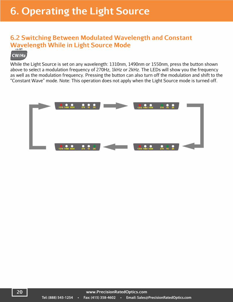
6.2 Switching Between Modulated Wavelength and Constant Wavelength While in Light Source Mode
While the Light Source is set on any wavelength: 1310nm, 1490nm or 1550nm, press the button shown above to select a modulation frequency of 270Hz, 1kHz or 2kHz. The LEDs will show you the frequency as well as the modulation frequency. Pressing the button can also turn off the modulation and shift to the “Constant Wave” mode. Note: This operation does not apply when the Light Source mode is turned off.
6. Operating the Light Source

Tel: (888) 545-1254 • Fax: (415) 358-4602 • Email: [email protected] 21
6.3 Switching on/off the “Auto-Recognition” mode of the Light Source and Power Meter
The wavelength “Auto-Recognition” feature is active if a pair of OLM-200 Series series devices are used as an OLTS and in “TWIN” mode. Press the “TWIN” button turn activate the “Auto-Recognition” mode. “TWIN” will then be displayed on the LCD. Press again to turn off “TWIN” mode.
Note: 1). Shown above are two OLM-200 Series devices in “TWIN” mode and successfully paired.
2). It is suggested to turn off the “TWIN” mode when using the device only in “Light Source” mode. The optical power output of Light Source while in “TWIN” mode places an extra load on the batteries. Keep in mind that the device cannot be simultaneously in “TWIN” mode and “Modulation” mode. When the “TWIN” mode is active, modulation of the Light Source is automatically deactivated.
4). The wavelength will be set automatically by the “Auto Recognition” mode when the Power Meter is in “TWIN” mode. In another words, the modulated signal of 270Hz, 1kHz and 2kHz cannot be recognized and received while the device is in “TWIN” mode.
6. Operating the Light Source

Tel: (888) 545-1254 • Fax: (415) 358-4602 • Email: [email protected]
7. OLM-200 Series “Data Manager” Software
7.1 “Data Manager” Software Requirements
Note:Before you attach the device to a PC using the supplied USB cable for the first time, you must install the OLM-200 Series “Data Manager” software from the CD included with your unit.
System requirementsMicrosoft Windows 2000 / XP
Minimum requirements:CPU: 600MHz Pentium processor or above RAM: 128MBGraphics Adapter: VGA256 color or above Hard disk: >300(MB) spare capacity Driver:8x speed CD-ROM or above Recommendatory Configuration: CPU: 1K(MHz) Pentium processor Memory: Above 256MBAdapter: SVGA16 or aboveHard disk: >300(MB) spare capacity Driver: 8 times speed CD-ROM or above
Tel: (888) 545-1254 • Fax: (415) 358-4602 • Email: [email protected] 23
7. OLM-200 Series “Data Manager” Software 7. OLM-200 Series “Data Manager” Software
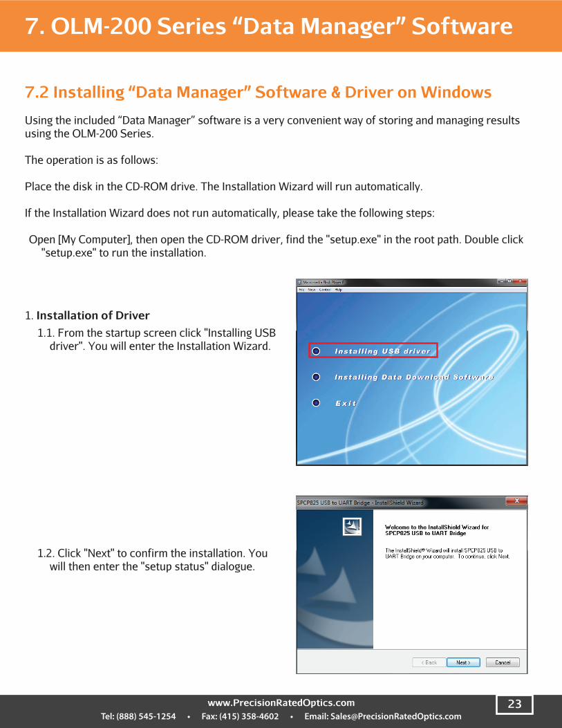
7.2 Installing “Data Manager” Software & Driver on Windows
Using the included “Data Manager” software is a very convenient way of storing and managing results using the OLM-200 Series.
The operation is as follows:
Place the disk in the CD-ROM drive. The Installation Wizard will run automatically.
If the Installation Wizard does not run automatically, please take the following steps:
Open [My Computer], then open the CD-ROM driver, find the "setup.exe" in the root path. Double click "setup.exe" to run the installation.
1. Installation of Driver1.1. From the startup screen click "Installing USB
driver". You will enter the Installation Wizard.
1.2. Click "Next" to confirm the installation. You will then enter the "setup status" dialogue.

Tel: (888) 545-1254 • Fax: (415) 358-4602 • Email: [email protected]
1.3. You will then enter the confirmation dialog. Click the "finish" button to finalize the installation.
2. Installation of Software2.1. From the startup screen click
"Installing Data Download Software". You will enter the Installation Wizard.
7. OLM-200 Series “Data Manager” Software
2.2. Click "Next" to continue the installation.

Tel: (888) 545-1254 • Fax: (415) 358-4602 • Email: [email protected] 25
2.3 Enter the "Select Installation Folder" dialogue. The default installation path is "C:/Program Files/Data Manager/Data Manager". If you wish to change the default installation path, you can click the "browse" button to change the path. After choosing your installation path, click the "Next" button to advance to the confirmation dialogue.
Note:If the Data Manager is to be used ONLY by you select the “Just Me” option, otherwise the “Everyone” option will suffice.
7. OLM-200 Series “Data Manager” Software
2.4. Click "Next" to confirm the installation. You will enter the "setup status" dialogue.
2.5 After the installation, you will enter "Finish" dialogue. Click "close" button to finish the installation.
Tel: (888) 545-1254 • Fax: (415) 358-4602 • Email: [email protected]
7.3 Starting the Software
After the installation of the USB driver and Data Manager, you can start the program in two ways:
1. Click [Start] menu --> [All Programs] --> [Data Manager], then click the “Data Manager” to start the program.
2. Or, after the installation, there will be an icon of “Data Manager” on the desktop.
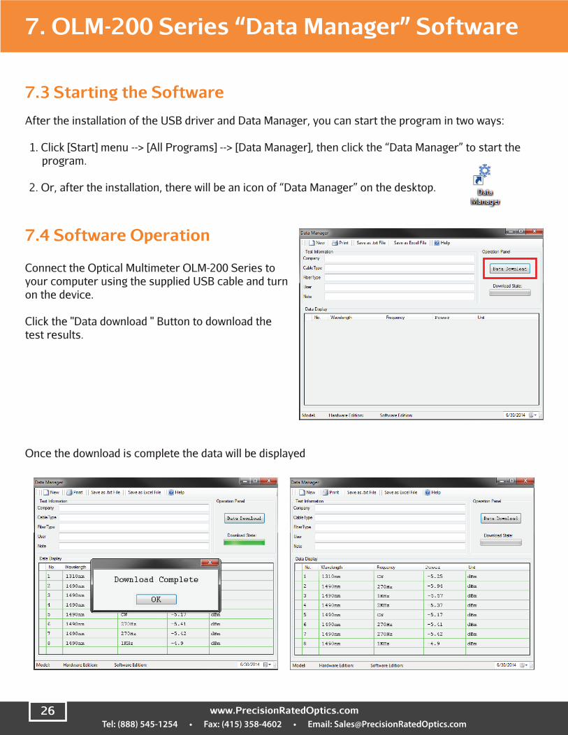
7.4 Software Operation
Connect the Optical Multimeter OLM-200 Series to your computer using the supplied USB cable and turn on the device.
Click the "Data download " Button to download the test results.
7. OLM-200 Series “Data Manager” Software
Once the download is complete the data will be displayed

Tel: (888) 545-1254 • Fax: (415) 358-4602 • Email: [email protected] 27
7. OLM-200 Series “Data Manager” Software
To save the file as a Text file (*.txt) click the corresponding button.
You can also save the file as an Excel document.(.xls)
Note: The computer must have Microsoft Office Excel to save in Excel format.
7. OLM-200 Series “Data Manager” Software

Tel: (888) 545-1254 • Fax: (415) 358-4602 • Email: [email protected]
7. OLM-200 Series “Data Manager” Software
You can also print the reports generated by the “Data Manager” software.
7.5 Uninstalling the Software
The Data Manager provides “Auto-Uninstall” function. This allows for easy removal of all components, program groups and shortcuts of the software.
1. Click the windows [Start] menu --> [All Programs] --> [Data Manager]. Select “Uninstall Data Manager”, then click the “Yes” Button to initiate the uninstall.
2. Another method to remove the software is to click [Add or Remove Programs] in the [Control Panel]. Click [Remove] to uninstall the software or the USB driver.
Tel: (888) 545-1254 • Fax: (415) 358-4602 • Email: [email protected] 29
8. Basic Maintenance● When not in use and not charging, disconnect the AC/DC adapter/charger and cover the ports with
the protective dust caps.
● It is recommended to clean the connector of the device often, as recommended by industry best practices. NEVER use anything to clean the ports other than approved optical cleaning pads and anhydrous alcohol is recommended. NEVER pour any liquid cleaner into the device.
9. Troubleshooting
1. If the system indicates that a port cannot be found while running Data Manager, please check if the USB cable is properly connected.
2. If the USB connection is normal but the port still cannot be found, please check the port information for the computer being used. You can find this information by clicking [Start], [Control Panel], [System Properties], [Hardware], and [Device Manager]. There should be an item named “Sunplus USB to Serial COM Port”. A yellow exclamation mark before the item means that the device is not properly connected to the PC. You can solve this by disconnecting the USB cable and reconnecting it. The yellow exclamation point should disappear when the device is properly connected and the USB connection is properly functioning. If there is still a problem, try another USB port.
10. Warranty Information
Three-Year Limited WarrantyPRO Products are warranted against manufacturer defects and workmanship for a period of three years from the date of delivery to the original customer. Any product found to be defective within the warranty period should be returned to an authorized PRO service center for repair, replacement and/or calibration.
ExclusionsThe warranty on your equipment if void if any of the following conditions exist:
● Unauthorized repair or modification, including battery replacement
● Misuse, negligence, or accident
Returning ProductTo return the device, contact a PRO service center and use your original packaging materials to ship the device. To serve you better, please specify the reasons for the return and any additional information that may assist us in diagnosing the equipment.All delivery and mails should be sent to the following address:

Tel: (888) 545-1254 • Fax: (415) 358-4602 • Email: [email protected]

Tel: (888) 545-1254 • Fax: (415) 358-4602 • Email: [email protected] 31

Precision Rated Optics, Inc. National Sales Office2030 Blue Heron CircleBirmingham, AL 35242
Precision Rated Optics, Inc. Corporate Office
Billing & ProcessingPO Box 877 Trexlertown, PA 18087
Precision Rated Optics, Inc.Product Distribution Center
Manufacturing & Testing9999 Hamilton Blvd
Breinigsville, PA 18031