Oklahoma Uniform Building Code Commission Presentation.pdf · Oklahoma Uniform Building Code...
122
Oklahoma Uniform Building Code Commission Residential Building Technical Committee Recommendations for the 2015 Edition of the International Residential Code® Presented: October 20, 2015 By: Mr. Todd Booze (Vice-Chairman) Commission Liaison: Mr. Curtis McCarty Committee Members: Chris Ramseyer (Professional Engineer/Chairman), Todd Booze (Residential Production Builder/Vice-Chairman), Larry Cagel (Residential Custom Builder), Sam Gresham (Residential Designer), John Moore (Inspector Small Jurisdiction), David Reed (Architect), John Taylor (Fire Representative), Joe Williford (Inspector Large Jurisdiction) Alternate Members: Greg Clark (Inspector Large/Small Jurisdiction), Mike Gilles (Residential Builder) 1
Transcript of Oklahoma Uniform Building Code Commission Presentation.pdf · Oklahoma Uniform Building Code...
Oklahoma Uniform Building Code Commission
Residential Building Technical Committee Recommendations for the 2015 Edition of the International Residential Code®
Presented: October 20, 2015
By: Mr. Todd Booze (Vice-Chairman)
Commission Liaison: Mr. Curtis McCarty
Committee Members: Chris Ramseyer (Professional Engineer/Chairman), Todd Booze
(Residential Production Builder/Vice-Chairman), Larry Cagel (Residential Custom Builder),
Sam Gresham (Residential Designer), John Moore (Inspector Small Jurisdiction), David Reed
(Architect), John Taylor (Fire Representative), Joe Williford (Inspector Large Jurisdiction)
Alternate Members: Greg Clark (Inspector Large/Small Jurisdiction), Mike Gilles (Residential
Builder)
1
General Commentary:
The Residential Building Technical Committee conducted a thorough formal review
of the 2015 Edition of the International Residential Code®; Chapters: Three , Four,
Five, Six, Seven, Eight, Nine, Ten, and Eleven at the request of the Oklahoma
Uniform Building Code Commission. The review process commenced on
Wednesday, February 11, 2015; in the Construction Industries Board/Oklahoma
Uniform Building Code Commission boardroom at Shepherd Mall,
2401 NW 23rd Street, Suite 2F, Oklahoma City, OK 73107.
Public Comment Forms:
Sixty-eight (68) public comment forms were received, plus two (2) revised forms for a
total of seventy (70) forms. Forty-four (44) public comment forms were approved as
submitted; eight (8) were approved with amendments; eight (8) were withdrawn and
ten (10)were denied.
2009 Rule Modifications Reviewed
Twenty-two (22) 2009 rule modifications were reviewed by the committee. Seven (7)
rule modifications have been recommended to be carried over as is. Fourteen (14) rule
modifications have been recommended to be carried over but modified. One (1) rule
modification has been recommended to be deleted from the current rules. 2
Chapter One – Scope and Administration
Unanimous vote to “Recognize Chapter One as written”
(3/24/2015 and 09/09/2015)
Chapter Two – Definitions
Unanimous vote to “Recognize Chapter Two subject to bringing it into alignment
with the Commercial Committee changes” (3/24/2015)
Unanimous vote to “Recognize Chapter Two as written” (6/8/2015)
Unanimous vote to “Recognize Chapter Two and approve as modified ”
(9/09/2015)
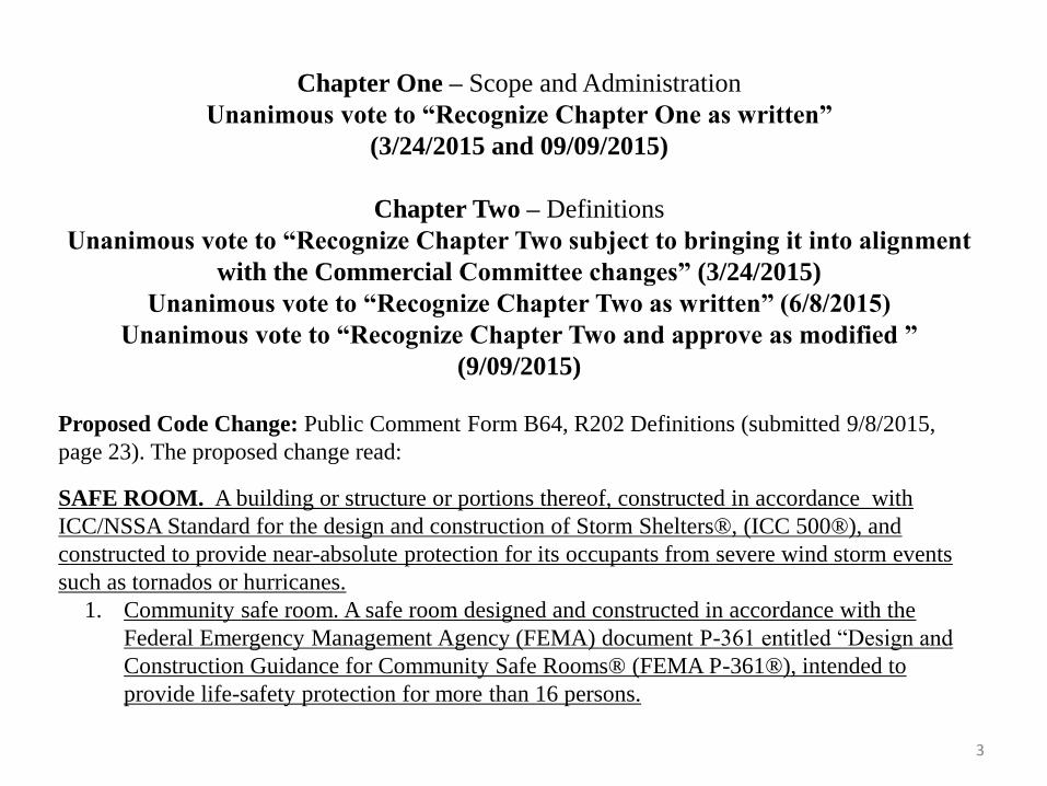
Proposed Code Change: Public Comment Form B64, R202 Definitions (submitted 9/8/2015,
page 23). The proposed change read:
SAFE ROOM. A building or structure or portions thereof, constructed in accordance with
ICC/NSSA Standard for the design and construction of Storm Shelters®, (ICC 500®), and
constructed to provide near-absolute protection for its occupants from severe wind storm events
such as tornados or hurricanes.
1. Community safe room. A safe room designed and constructed in accordance with the
Federal Emergency Management Agency (FEMA) document P-361 entitled “Design and
Construction Guidance for Community Safe Rooms® (FEMA P-361®), intended to
provide life-safety protection for more than 16 persons.
3
4
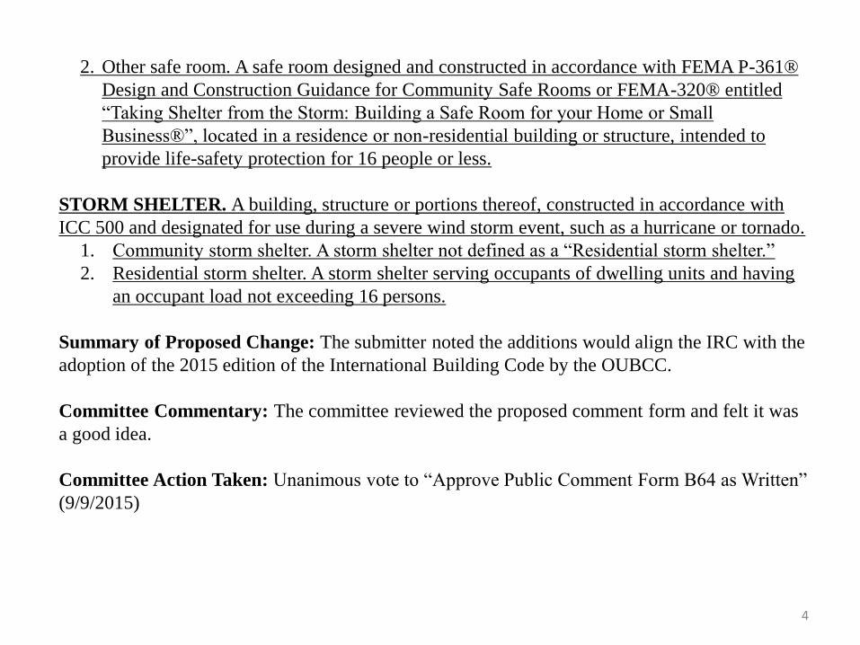
2. Other safe room. A safe room designed and constructed in accordance with FEMA P-361®
Design and Construction Guidance for Community Safe Rooms or FEMA-320® entitled
“Taking Shelter from the Storm: Building a Safe Room for your Home or Small
Business®”, located in a residence or non-residential building or structure, intended to
provide life-safety protection for 16 people or less.
STORM SHELTER. A building, structure or portions thereof, constructed in accordance with
ICC 500 and designated for use during a severe wind storm event, such as a hurricane or tornado.
1. Community storm shelter. A storm shelter not defined as a “Residential storm shelter.”
2. Residential storm shelter. A storm shelter serving occupants of dwelling units and having
an occupant load not exceeding 16 persons.
Summary of Proposed Change: The submitter noted the additions would align the IRC with the
adoption of the 2015 edition of the International Building Code by the OUBCC.
Committee Commentary: The committee reviewed the proposed comment form and felt it was
a good idea.
Committee Action Taken: Unanimous vote to “Approve Public Comment Form B64 as Written”
(9/9/2015)
5
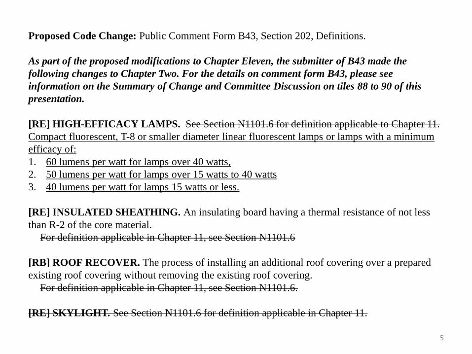
Proposed Code Change: Public Comment Form B43, Section 202, Definitions.
As part of the proposed modifications to Chapter Eleven, the submitter of B43 made the
following changes to Chapter Two. For the details on comment form B43, please see
information on the Summary of Change and Committee Discussion on tiles 88 to 90 of this
presentation.
[RE] HIGH-EFFICACY LAMPS. See Section N1101.6 for definition applicable to Chapter 11.
Compact fluorescent, T-8 or smaller diameter linear fluorescent lamps or lamps with a minimum
efficacy of:
1. 60 lumens per watt for lamps over 40 watts,
2. 50 lumens per watt for lamps over 15 watts to 40 watts
3. 40 lumens per watt for lamps 15 watts or less.
[RE] INSULATED SHEATHING. An insulating board having a thermal resistance of not less
than R-2 of the core material.
For definition applicable in Chapter 11, see Section N1101.6
[RB] ROOF RECOVER. The process of installing an additional roof covering over a prepared
existing roof covering without removing the existing roof covering.
For definition applicable in Chapter 11, see Section N1101.6.
[RE] SKYLIGHT. See Section N1101.6 for definition applicable in Chapter 11.
6
[RE] SLEEPING UNIT. See section N1101.6 for definition applicable in Chapter 11.
[RB] SUNROOM. A one-story structure attached to a dwelling with a glazing area in excess of 40
percent of the gross area of the structure’s exterior walls and roof.
For definition applicable in Chapter 11, see Section N1101.6
[RB] THERMAL ISOLATION. Physical and space conditioning separation from conditioned
space(s) consisting of existing or new walls, doors or windows. The conditioned space(s) shall be
controlled as separate zones for heating and cooling or conditioned by separate equipment.
For definition applicable in Chapter 11, see Section N1101.6.
[RE] U-FACTOR, THERMAL TRANSMITTANCE. See Section N1101.6 for definition
applicable in Chapter 11. The coefficient of heat transmission (air to air) through a building
envelope component or assembly, equal to the time rate of heat flow per unit area and unit
temperature difference between the warm side and cool side air films (Btu/h * square feet *
Fahrenheit).
VENTILATION. The natural or mechanical process of supplying conditioned or unconditioned air
to, or removing such air from, any space.
For definition applicable in Chapter 11, see Section N1101.6.
WHOLE-HOUSE MECHANICAL VENTILATION SYSTEM. An exhaust system, supply
system or combination thereof that is designed to mechanically exchange indoor air for outdoor air
where operating continuously or through a programmed intermittent schedule to satisfy the whole-
house ventilation rate.
For definition applicable in Chapter 11, see Section N1101.6
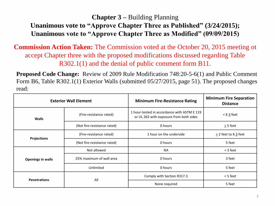
Chapter 3 – Building Planning
Unanimous vote to “Approve Chapter Three as Published” (3/24/2015);
Unanimous vote to “Approve Chapter Three as Modified” (09/09/2015)
Commission Action Taken: The Commission voted at the October 20, 2015 meeting ot
accept Chapter three with the proposed modifications discussed regarding Table
R302.1(1) and the denial of public comment form B11.
Proposed Code Change: Review of 2009 Rule Modification 748:20-5-6(1) and Public Comment
Form B6, Table R302.1(1) Exterior Walls (submitted 05/27/2015, page 51). The proposed changes
read:
2009 Modification:
7
Exterior Wall Element Minimum Fire-Resistance Rating Minimum Fire Separation
Distance
Walls (Fire-resistance rated)
1 hour-tested in accordance with ASTM E 119 or UL 263 with exposure from both sides
< 5 3 feet
(Not fire-resistance rated) 0 hours > 5 feet
Projections (Fire-resistance rated) 1 hour on the underside > 2 feet to 5 3 feet
(Not fire-resistance rated) 0 hours 5 feet
Openings in walls
Not allowed NA < 3 feet
25% maximum of wall area 0 hours 3 feet
Unlimited 0 hours 5 feet
Penetrations All Comply with Section R317.3 < 5 feet
None required 5 feet
8
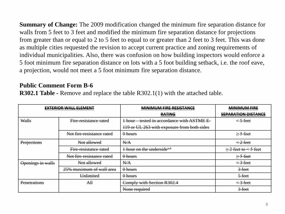
Summary of Change: The 2009 modification changed the minimum fire separation distance for
walls from 5 feet to 3 feet and modified the minimum fire separation distance for projections
from greater than or equal to 2 to 5 feet to equal to or greater than 2 feet to 3 feet. This was done
as multiple cities requested the revision to accept current practice and zoning requirements of
individual municipalities. Also, there was confusion on how building inspectors would enforce a
5 foot minimum fire separation distance on lots with a 5 foot building setback, i.e. the roof eave,
a projection, would not meet a 5 foot minimum fire separation distance.
Public Comment Form B-6
R302.1 Table - Remove and replace the table R302.1(1) with the attached table.
EXTERIOR WALL ELEMENT MINIMUM FIRE RESISTANCE
RATING
MINIMUM FIRE
SEPARATION DISTANCE
Walls Fire-resistance rated 1 hour – tested in accordance with ASTME E-
119 or UL 263 with exposure from both sides
< 5 feet
Not fire-resistance rated 0 hours ≥ 5 feet
Projections Not allowed N/A < 2 feet
Fire-resistance rated 1 hour on the undersidea,b ≥ 2 feet to < 5 feet
Not fire-resistance rated 0 hours ≥ 5 feet
Openings in walls Not allowed N/A < 3 feet
25% maximum of wall area 0 hours 3 feet
Unlimited 0 hours 5 feet
Penetrations
All Comply with Section R302.4 < 3 feet
None required 3 feet
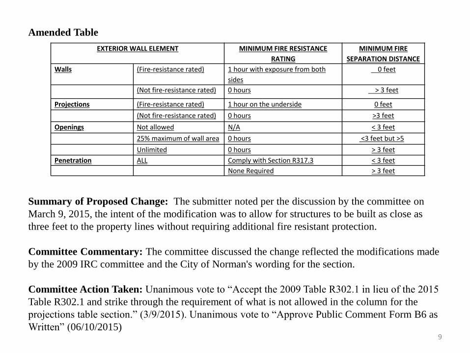
Summary of Proposed Change: The submitter noted per the discussion by the committee on
March 9, 2015, the intent of the modification was to allow for structures to be built as close as
three feet to the property lines without requiring additional fire resistant protection.
Committee Commentary: The committee discussed the change reflected the modifications made
by the 2009 IRC committee and the City of Norman's wording for the section.
Committee Action Taken: Unanimous vote to “Accept the 2009 Table R302.1 in lieu of the 2015
Table R302.1 and strike through the requirement of what is not allowed in the column for the
projections table section.” (3/9/2015). Unanimous vote to “Approve Public Comment Form B6 as
Written” (06/10/2015)
EXTERIOR WALL ELEMENT MINIMUM FIRE RESISTANCE
RATING
MINIMUM FIRE
SEPARATION DISTANCE
Walls (Fire-resistance rated) 1 hour with exposure from both
sides
0 feet
(Not fire-resistance rated) 0 hours > 3 feet
Projections (Fire-resistance rated) 1 hour on the underside 0 feet
(Not fire-resistance rated) 0 hours >3 feet
Openings Not allowed N/A < 3 feet
25% maximum of wall area 0 hours <3 feet but >5
Unlimited 0 hours > 3 feet
Penetration ALL Comply with Section R317.3 < 3 feet
None Required > 3 feet
Amended Table
9
Proposed Code Change: Public Comment Form B7, Section R302.5.1 Opening Protection
(submitted 05/27/2015, page 53). The proposed change read:
R302.5.1 Opening protection. Openings from a private garage directly into a room used for
sleeping purposes shall not be permitted. Other openings between the garage and residence shall
be equipped with solid wood doors not less than 1 3/8 inches (35mm) in thickness, solid or
honeycomb-core steel doors not less than 1 3/8 inches (35 mm) thick, or 20- minute fire-rated
doors. equipped with a self- closing device.
Summary of Proposed Change: The item was first discussed at the March 9, 2015 meeting. A
motion was made and vote taken, after which a comment form was submitted. The submitter
noted the committee discussed the section and felt the new addition of installing self-closing
devices would ultimately be a burden to homeowners and that in many cases the closers would
be removed, modified, or not maintained and would be largely ineffective.
Committee Commentary: The committee discussed the modification at the March 9, 2015
meeting. The proposed comment form was submitted as a result of that discussion. When the
comment form was brought up for review, there was no additional discussion.
Committee Action Taken: Unanimous vote to “Remove the wording ‘equipped with a self-
closing device’ ” (3/09/2015) Unanimous vote to “Approve as Public Comment Form B-7 as
Written” (06/10/2015)
10

11
Proposed Code Change: Public Comment Form B43, Section 303.1, Habitable Rooms.
As part of the proposed modifications to Chapter Eleven, the submitter of B43 made the following
changes to Chapter Two. For the details on comment form B43, please see information on the
Summary of Change and Committee Discussion on tiles 88 to 90 of this presentation.
R303.1 Habitable Rooms. Habitable rooms shall have an aggregate glazing area of not less than 8
percent of the floor area of such rooms. Natural ventilation shall be through windows, skylights,
doors, louvers or other approved openings to the outdoor air. Such openings shall be provided with
ready access or shall otherwise be readily controllable by the building occupants. The openable area
to the outdoors shall not be less than 4 percent of the floor area being ventilated.
Exceptions:
1. The glazed areas need not be openable where the opening is not required by Section R310 and
an approved mechanical ventilation system capable of producing 0.35 air change per hour in the
room is installed or a whole-house mechanical ventilation system is installed in accordance
with M1507 capable of supplying outdoor ventilation air of 15 cubic feet per minute (cfm) per
occupant computed on the basis of two occupants for the first bedroom and one occupant for
each additional bedroom.
2. The glazed areas need not be installed in rooms where Exception 1 is satisfied and artificial
light is provided that is capable of producing an average illumination of 6 footcandles (65 lux)
over the area of the room at a height of 30 inches (762 mm) above the floor level.
3. Use of sunroom and patio covers, as defined in Section R202, shall be permitted for natural
ventilation if in excess of 40 percent of the exterior sunroom walls are open, or are enclosed
only by insect screening.
12
Proposed Code Change: Public Comment Form B43, Section R303.4, Mechanical ventilation.
As part of the proposed modifications to Chapter Eleven, the submitter of B43 made the
following changes to Chapter Two. For the details on comment form B43, please see
information on the Summary of Change and Committee Discussion on tiles 88 to 90 of this
presentation.
Section R303.4 Mechanical ventilation. Where the air infiltration rate of a dwelling unit is 5 air
changes per hour or less where tested with a blower door at a pressure of 0.2 inch w.c. (50 Pa) in
accordance with Section N1102.4.1.2, the dwelling unit shall be provided with whole-house
mechanical ventilation in accordance with Section M1507.3.
Proposed Code Change: Public Comment Form B31, Section R311.1 Means of Egress.
(submitted 07/22/2015, page 63). The proposed change read:
R311.1 Means of egress. Dwellings and garages (attached or detached from the dwelling) shall be
provided with a means of egress in accordance with this section. The means of egress shall
provide a continuous and unobstructed path of vertical and horizontal egress travel from all
portions of the dwelling to the required egress door without requiring travel through a garage. The
means of egress from the garage may travel through the adjacent dwelling. The required egress
door shall open directly into a public way or to a yard or court that opens to a public way.
R311.2 Egress door. Not less than one egress door shall be provided for each dwelling unit or
garage. The egress door shall be side-hinged, and shall provide a clear width of not less than 32
inches (813 mm) where measured between the face of the door and the stop, with the door open
90 degrees (1.57 rad). The clear height of the door opening shall not be less that 78 inches (1981
mm) in height measured from the top of the threshold to the bottom of the stop. Other doors shall
not be required to comply with these minimum dimensions. Egress doors shall be readily openable
from inside the dwelling or garage without the use of a key or special knowledge or effort.
Summary of Proposed Change : The submitter noted most overhead garage doors were
equipped with electric garage door openers and it would seem to be a prudent idea to require
another way out of the garage when the power went out or the opener became inoperable or
jammed. He noted it would be especially important for a young or disabled person who might not
be able to reach the pull cord to disengage the opener.
13
Committee Commentary: The committee discussed the form and noted the problem was more of
an issue with a detached garage. They discussed the current code requirements for means of egress
and if the code already required means of egress other than into the dwelling and if a window
could be an option.
Committee Action Taken: Unanimous vote to “Approve Public Comment Form B31 as Written”
(08/12/2015)
14
Proposed Code Change: Review of 2009 rule modification 748:20-5-6(2) and Public Comment
Forms B8 (withdrawn) & B18, Section R311.7.5.1 Risers (submitted 05/27/2015 and
06/26/2015, page 64). The proposed modifications read:
2009 Modification:
Section 311.7.4.1 Riser height. The maximum riser height shall be 7 3/4 inches (196 mm). The
riser shall be measured vertically between leading edges of the adjacent treads. The greatest
riser height within any flight of stairs shall not exceed the smallest by more than 3/8 inch (9.5
mm) at rough-in. Top and bottom riser may vary by 3/4 inch at final inspection, not to exceed 7
3/4 of an inch (196 mm).
Summary of Change: The 2009 Residential Building Technical Committee made the change to
increase the tolerance at the top and bottom landing area of a staircase to 3/4" due to varying
types of flooring material that can be used at those locations. The committee determined it was
not always possible to maintain 3/8" tolerance in those areas due to homes that sell at various
stages of construction with new homeowners changing the flooring materials throughout the
process. The committee determined the amendment did not affect the safety intent of the code.
The code required minimum variation between risers of 3/8" through the risers while a person
was in rhythm walking up and down stairs. The variation at the top and bottom did not affect
safety due to the landing areas when the rhythm is already changing. The amendment further
clarified the measuring of the riser height in the section should be done at the rough-in stage,
prior to flooring materials becoming an influence to the riser height.
15
16
B-18
R311.7.5.1 Risers. The riser height shall be not more than 7 3/4 inches (196 mm). The riser shall
be measured vertically between leading edges of the adjacent treads. The greatest riser height
within any flight of stairs shall not exceed the smallest by more than 3/8 inch (9.5mm). Risers
shall be vertical or sloped from the underside of the nosing of the tread above at an angle not more
than 30 degrees (0.51 rad) from the vertical. Open risers are permitted provided that the openings
located more than 30 inches (762 mm), as measured vertically, to the floor or grade below do not
permit the passage of a 4-inch–diameter (102 mm) sphere.
Exceptions:
1. The opening between adjacent treads is not limited on spiral stairways.
2. The riser height of spiral stairways shall be in accordance with Section R311.7.10.1
3. The top and bottom riser in each flight of stairs may vary by ¾ inch.
Summary of Proposed Change: The submitter stated the 2015 Building Residential Technical
Committee felt this language was more concise than what was provided by the code.
Committee Commentary: The committee discussed Public Comment Form B8 at both the May
9, 2015, and June 10, 2015 meetings. The consensus was to revise the form and the submitter
withdrew the form. The committee discussed B18, which was a revision to the Section based on
the previous discussion, at the July 8, 2015 meeting.
Committee Action Taken: Unanimous vote to modify Section 311.7.5.1 Risers by moving the
last sentence of the paragraph into the Exception as item 3” (3/9/2015) Unanimous vote to
“Approve Public Comment Form B-18 as Written” (07/08/2015)
Proposed Code Change: Review of Rule Modifications 748:20-5-6(3), 748:20-5-6(4) and Public
Comment Form B9, Section R313.2 One and two-family dwellings automatic fire systems and its
exception and Section R313.2.1 Design and installation, (submitted 05/27/2015, page 66). The
proposed change read:
2009 ORIGINAL CODE LANGUAGE:
R313.2 One- and two-family dwellings automatic fire systems. Effective January 1, 2011, an
automatic residential fire sprinkler system shall be installed in one- and two-family dwellings.
Exception: An automatic residential fire sprinkler system shall not be required for additions or
alterations to existing buildings that are not already provided with an automatic residential
sprinkler system.
2009 ORIGINAL CODE LANGUAGE:
R313.2.1 Design and installation. Automatic residential fire sprinkler systems shall be designed
in accordance with Section P2904 or NFPA 13D.
2009 Modifications: The sections were moved into a created appendix and were not adopted as a
minimum standard for residential construction within the state.
Summary of Change: The 2009 Residential Building Technical Committee discussed the issue of
residential fire sprinkler systems and ultimately decided they were not in best interest of the State.
Some of the issues discussed by the committee were:
17
18
1. The national trend to remove the section by other states that had adopted the 2009 IRC
because they were an unnecessary burden and were an unreliable measure in one- and two-
family dwellings.
2. The local jurisdiction's ability to determine if the requirement was needed.
3. The lack of significant safety enhancement vs. hardwired smoke alarms. They discussed it
was an unnecessary redundancy when considering it as an egress system on top of the current
requirement for hardwired smoke alarms with battery backup.
4. New homes were much more fire resistant.
5. Durability of the systems and sprinkler performance.
B-9
R313.2 – One and two-family dwellings automatic fire systems. An automatic residential fire
sprinkler system shall be installed in one- and two-family dwellings. Exception: An automatic
residential fire sprinkler system shall not be required for additions or alterations to existing
buildings that are not already provided with an automatic residential sprinkler system.
R313.2.1 Design and installation. Automatic residential fire sprinkler system shall be designed
and installed in accordance with Section P2904 or NFPA 13D.
Summary of Proposed Change: The submitter noted, consistent with the prior Technical
Committee, he felt that requiring Automatic Sprinklers on all new Single Family Dwellings was
ultimately to costly and constraining.
19
Committee Commentary: The committee reviewed Public Comment Form B9 and determined
moving the sections to an appendix was the correct thing to do.
Committee Action Taken: Unanimous vote to “Move Sections R313.2 One- and two-family
dwellings automatic fire systems and R313.2.1 Design and installation into an appendix”
(3/9/2015) Unanimous vote to “Approve Public Comment Form B9 as Written” (06/10/2015)
Proposed Code Change: Public Comment Form B10, Section R314.2.2 Alterations, repairs and
additions (submitted 05/27/2015, page 67). The proposed change read:
R314.2.2 – Alterations, repairs and additions. Where alterations, repairs or additions requiring
a permit occur, or where one or more sleeping rooms are added or created in existing dwellings,
the individual dwelling unit shall be equipped with smoke alarms located as required for new
dwellings.
Exceptions:
1. Work involving the exterior surfaces of dwellings such as the replacement of roofing or
siding, the addition or replacement of windows and doors, or the addition of a porch or deck
are exempt from the requirements of this section.
2. Installation, alteration or repairs of electrical, plumbing or mechanical systems are exempt
from the requirements of this section.
Summary of Proposed Change: The submitter stated the change that was made with the
comment form was to add electrical installation, alterations or repairs to the section.
Committee Commentary: The committee reviewed the B10 and felt that obligating compliance
with this section when the scope of work was minor electrical work was not reasonable.
Committee Action Taken: Unanimous vote to “Approve Public Comment Form B10 as Written”
(06/10/2015)
20
Proposed Code Change: Public Comment Form B11, Section R314.3 # 4 Location (submitted
05/27/2015, page 67). The proposed change read:
R314.2.3 Location. Smoke alarms shall be installed in the following locations:
1. In each sleeping room.
2. Outside each separate sleeping area in the immediate vicinity of the bedrooms.
3. On each additional story of the dwelling, including basements and habitable attics and not
including crawl spaces and uninhabitable attics. In dwellings or dwelling units with split
levels and without an intervening door between the adjacent levels, a smoke alarm installed
on the upper level shall suffice for the adjacent lower level provided that the lower level is
less than one full story below the upper level.
4. Smoke alarms shall be installed not less than 3 feet (914 mm) horizontally from the door or
opening of a bathroom that contains a bathtub or shower unless this would prevent placement
of a smoke alarm required by Section R314.3.
Summary of Proposed Change: The submitter felt the new addition, (specifically Item 4),was
confusing. He stated while there were published code interpretations stating the section was to
clarify that required smoke detectors should not be placed closer than three feet to bathrooms with
tubs and showers, the language was confusing. He noted it could be easily interpreted that smoke
detectors were required within three feet of bathrooms with tubs and showers. He noted that
installation instructions for the products provide requirements for installation.
21
22
Committee Commentary: The committee initially discussed the section at the March 9, 2015
meeting and made a motion to delete item 4 from the list of locations. A subsequent comment
form was submitted and reviewed. The committee discussed that the current language was
confusing and the intent was hard to figure out, if the language should be kept and reworded or if
it should be completely deleted and how that would effect enforcement.
Committee Action Taken: Unanimous vote to “Remove Item 4” (03/09/2015), Vote to “Strike
the language, and approve Public Comment Form B-11” (06/10/2015)
23
Proposed Code Change: Review of Rule Modification 748:20-5-6(5) on Section R315.1 Carbon
monoxide alarms (page 68). The original modification read as follows:
2009 Modification:
For new construction, an approved carbon monoxide alarm shall be installed outside of each
separate sleeping area in the immediate vicinity of the bedrooms in dwelling units within which
fuel-fired appliances are installed and in dwelling units that have attached garages. Exception: If a
residence with an attached garage has a sealed door between the residence and the garage; and no
fuel burning appliances in the residence, then carbon monoxide detection is not required within the
residence.
Summary of Change: The 2009 IRC committee added the exception to remove the need for a
carbon monoxide alarms in homes where there were no fuel burning appliances within the
conditioned envelope of the structure, i.e. no source of carbon monoxide. The committee noted
carbon monoxide alarms had been used in homes in recent years and were problematic with false
alarms being caused by common household products used in the homes. In addition to their
sensitivity to dust particles pulled across their sensors from HVAC operation created an
unacceptable nuisance to the homeowner and many times lead to the occupant disabling them. The
committee hoped in the next code cycle they would be reviewed, and the industry would have made
improvements to product performance and acceptance could be determined at that time.
Committee Commentary: The 2015 committee reviewed the rule modification and discussed the
section. They determined the section had been revised and the exception was no longer needed.
Committee Action Taken: Unanimous vote to “Delete the 2009 rule modification and revert to
2015 code language” (3/09/2015)
Proposed Code Change: Public Comment Form B12, Section R315.2.2 Alterations, repairs and
addition (submitted 05/27/2015, page 68). The proposed change read:
R315.2.2 Alterations, repairs and addition. Where alterations, repairs or additions requiring a
permit occur, or where one or more sleeping rooms are added or created in existing dwellings, the
individual dwelling unit shall be equipped with carbon monoxide alarms located as required for
new dwellings.
Exceptions:
1. Work involving the exterior surfaces of dwellings, such as the replacement of roofing or
siding, or the addition or replacement of windows or doors, or the addition of a porch or deck,
is exempt from the requirements of this section.
2. Installation, alteration or repairs of electrical, plumbing or mechanical systems are exempt
from the requirements of this section.
Summary of Proposed Change: The submitter noted after discussion the committee felt
requiring compliance with this section when the scope of work was minor electrical work was not
reasonable.
Committee Commentary: The committee discussed the section and a subsequent Public
Comment Form was submitted. The committee reviewed the form and there was no further
discussion.
Committee Action Taken: Unanimous vote to “Approve Public Comment Form B12 as Written”
(06/10/2015)
24
Proposed Code Change: Review of 2009 Rule Modification 748:20-5-6(6) and Public Comment
Form B65, Section R323, Storm Shelters (submitted 09/08/2015, page 76). The proposed change
read:
2009 Modification:
R323.1 General. This section applies to the construction of storm shelters when constructed as
separate detached buildings or when constructed as safe rooms within buildings for the purpose of
providing safe refuge from storms that produce high winds, such as tornados and hurricanes. In
addition to other applicable requirements in this code, storm shelters shall be constructed in
accordance with one of the following: ICC/NSSA 500 or FEMA 320 or other equivalent engineered
system.
Summary of Change: The 2009 committee felt that consumers chose to build safe areas in homes
for varying purposes and the specification levels should not be required in all cases to achieve such
a high level of construction. They felt there were many other standards that met the intent of the
section and those should be allowed to be utilized. They noted the 2009 IRC did not dictate that a
storm shelter had to be built in a home, therefore the code should not dictate what type of
construction should be achieved if the consumer chose to build one.
B65
R323 STORM SHELTERS AND SAFE ROOMS
R323.1 General. This section applies to the construction of above or below ground storm shelters
and safe rooms where constructed as separate detached buildings or where constructed as safe
rooms within buildings or rooms within buildings, structures, or portions thereof for the purpose of 25
26
providing refuge from storms that produce high winds, such as tornados and hurricanes. Any room
or structure, as may be used as a place of refuge during a severe wind storm event, shall not be
defined as a storm shelter or safe room unless specifically designed to the requirements as listed in
Section 323. In addition to other applicable requirements in this code storm shelters shall be
constructed in accordance with ICC/NSSA 500.
R323.2 Definitions. The following terms are defined in Chapter 2 of this code:
SAFE ROOM.
Community safe room.
Other safe room.
STORM SHELTER.
Community storm shelter.
Residential storm shelter.
Summary of Proposed Change: The submitter sought to align the section with the adoption of
the 2015 International Building Code® by the OUBCC.
Committee Commentary: The committee reviewed rule modification and felt the comment form
would better align the section to the 2015 IBC adoption.
Committee Action Taken: Unanimous vote to “Approve Public Comment Form B65 as Written”
(9/9/2015)
Proposed Code Change: Motion from March 9, 2015 meeting and Public Comment Forms B2 and
B14, Section R326 Swimming Pools, Spas and Hot Tubs (submitted 04/27/2015 and 05/27/2015,
page 77). The proposed changes read:
B14 Modification (B2 and B14 were the same except B14 corrected the section heading from
324 to 326):
Section 326 SWIMMING POOLS, SPAS AND HOT TUBS
R326.1 General. The design and construction of pools and spas shall comply with the
International Swimming Pool and Spa Code. Residential Swimming Pools, spas and hot tubs
requiring a permit shall comply with R326.2 through R326.4.
R326.2 Enclosure. Swimming pools shall be completely enclosed by a fence or barrier not less
than 4 feet (1290 mm) in height or a screen enclosure. Openings in the fence or barrier shall
not permit the passage of a 4-inch-diameter (102 mm) sphere.
Exceptions:
1. Swimming pools, spas and hot tubs on lots in excess of 2 acres are exempt from the
requirements.
2. A swimming pool with a power safety cover or a spa with a safety cover complying with
ASTM F 1346 need not comply with this section.
R326.3 Gates. Exterior pedestrian access doors or gates shall be self-closing and have a self-
latching device. Doors or gates other than pedestrian access doors or gates shall have a self-
latching device. Where the release mechanism of the self-latching device is located less than 54
inches (1372 mm) from the bottom of the door or gate, the release mechanism shall be located on
the pool side of the
27
door or gate 3 inches (76 mm) or more, below the top of the door or gate, and the door or gate and
barrier shall be without openings greater than 1/2 inch (12.7 mm) within 18 inches (457 mm) of the
release mechanism. Exception: Gates equipped with a locking device.
R326.4 Entrapment avoidance. Suction outlets shall be designed and installed in accordance
with ANSI/APSP-7.
2009 Appendix G (to be added to the newly created Appendix in the 2015 code for Swimming
Pools, Spas and Hot Tubs:
Summary of Proposed Change: The committee discussed the section during the March 9, 2015
meeting. During the discussion one of the members made a motion that was voted on to put the
2009 IRC Appendix G into the Appendix of the 2015 code. The submitter of B2 noted historically,
there had been no adopted standard for Swimming Pool Barriers in the state and it appeared likely
the new Section 326 would not be adopted and the following was a reasonable alternative. He
added the requirements were generally consistent with many Home Owners Insurance Providers
and largely consistent with the IBC requirements for Public Pools. The submitter of B14 noted the
committee felt that the International Swimming Pool and Spa Code would require a lot more
deliberation before such a standard was suddenly imposed on the contractors and homeowners in
the state. In order to create a standard, it was agreed the proposed requirements which are largely
consistent with the IBC would be a good minimum standard for pools
28
29
Committee Commentary: The Residential Building Technical Committee first discussed the issue
at the March 9, 2015 meeting. A motion was made and unanimously approved to move the entire
section into the next available appendix. The committee also voted to bring forward the 2009
Appendix G and add it to the next available appendix in the 2015 code. Two comment forms were
then submitted, B2 & B14. The committee reviewed comment form B2 at the May 11, 2015
meeting. They discussed that the language came from the commercial code; that the modification
added a standard for the pool installer to provide an entrapment device; that the comment form
added safety to the pool owners at a minimum cost, and the fencing requirements. Form B14 was
reviewed at the August 12, 2015 meeting. The committee noted it was strictly a clean-up item and
no discussion took place.
Committee Action Taken: Unanimous vote to “move Section R326 Swimming Pools, Spas and
Hot tubs to the next available appendix” (3/9/2015), Unanimous vote to “Add the 2009 Appendix
G to the new appendix for Swimming Pools, Spas and Hot tubs (3/9/2015) Unanimous vote to
“Approve Public Comment Form B2 as Written” (06/10/2015); Unanimous vote to “Approve B14
as Written” (8/12/2015)
Chapter 4 – Foundation
Unanimous vote to “Approve Chapter Four as Published” (3/24/2015)
Unanimous vote to “Approve Chapter Four as Modified” (8/12/2015)
Unanimous vote to “Approve Chapter Four as Modified” (9/09/2015)
Proposed Code Change: Review of 2009 Rule Modification 748:20-5-7(1) and Public Comment
Form B24, Addition to Section 402.2 Concrete (submitted 07/20/2015, page 80). The proposed
change read:
2009 Modification:
Section 402.2 Concrete. Concrete shall have a minimum specified compressive strength of f'c, as
shown in Table 402.2. Concrete subject to moderate or severe weathering as indicated in Table
301.2(1) shall be air entrained as specified in Table R402.2. The maximum weight of fly ash,
other pozzolans, silica fume, slag or blended cements that is included in concrete mixtures for
garage floor slabs and for exterior porches, carport slabs and steps that will be exposed to deicing
chemicals shall not exceed the percentages of the total weight of cementitious materials specified
in Section 4.2.3 or ACI 318. Materials used to produce concrete and testing thereof shall comply
with the applicable standards listed in Chapter 3 of ACI 318 or ACI 332. Exception: Interior
concrete slabs on grade and enclosed garage slabs are not required to be air entrained.
30
31
Summary of Change: The 2009 building committee noted the primary reason for air entrainment
in the slabs was that freeze-thaw damage to concrete is directly related to the number of cycles of
freezing and thawing the concrete was subjected to. They noted for concrete that was only exposed
to freezing and thawing during the construction period of the structure, the number of freeze-thaw
cycles was inconsequential to the long term durability of the concrete. They noted air entrainment
additives counteract the performance of other additives to the concrete. They noted an example of
water repellant additives used to prevent subsurface migration of moisture and vapor that was
counteracted when the concrete was entrained with air. They noted air entrainment caused many
finishing issues that prohibit the desire of consumers for smooth trowel floors that may remain
exposed stained and sealed.
B24
R402.2 – Concrete. Concrete shall have a minimum specified compressive strength of f” c, as
shown in Table R402.2. Concrete subject to moderate or severe weathering as indicated in Table
R301.2(1) shall be air entrained as specified in Table R402.2. The maximum weight of fly ash,
other pozzolans, silica fume, slag or blended cements that is included in concrete mixture for
garage floor slabs and for exterior porches, carport slabs and steps that will be exposed to deicing
chemicals shall not exceed the percentages of the total weight of cementitious materials specified
in Section 19.3.3.4 of ACI 318. Materials used to produce concrete and testing thereof shall comply
with the applicable standards listed in Chapters 19 and 20 of ACI 318 or ACI 332. Exception:
Interior concrete slabs on grade and enclosed garage slabs are not required to be air-entrained.
Summary of Proposed Change: The submitter noted, in the climate zone there has not been any
historic problems with freezing and thawing of garage floors. He added, hard steel trowel finish
of slabs generally removed the air entrainment.
Committee Commentary: The committee initially discussed the section in reference to the 2009
rule modification at the meeting on April 15, 2015. They discussed modifying some of the
footnotes associated with Table R402.2 Minimum Specified Compressive Strength of Concrete, or
if the 2009 modification that added an exception to Section 402.2 should be carried forward. The
committee unanimously voted to carry forward the 2009 modification. A subsequent public
comment form was submitted for the change and was also unanimously voted on.
Committee Action Taken: Unanimous vote to “Add an exception to Section 402.2” (04/15/2015),
Unanimous vote to “Approve Public Comment Form B-24 as Written” (08/12/2015)
32
33
Proposed Code Change: Motion from April 15, 2015 meeting, Table 403.1(1) Minimum width
and Thickness for Concrete Footings for Light-frame Construction (inches)a,b, Table 403.1(2)
Minimum Width and Thickness for Concrete Footings for Light-frame Construction with Brick
Veneer (Inches)a,b, and Table 403.1(3) Minimum Width and Thickness for Concrete Footings with
Cast-in-place Concrete or Fully Grouted Masonry Wall Construction (inches)a,b. (page 81)The
proposed change read:
Remove footnote “B” from each of the tables:
a. Interpolation allowed. Extrapolation is not allowed.
b. Based on 32-foot-wide house with load-bearing center wall that carries half of the tributary
attic, and floor framing. For every 2 feet of adjustment to the width of the house add or subtract 2
inches of footing width and 1 inch of footing thickness (but not less than 6 inches thick).
Summary of Change: The issue was brought forward by a committee member during discussion
on the chapter. His concern was the footnote could change the design of the house.
Committee Commentary: The committee discussed how the footnote would address the width of
the house and the span of the roof; examples of different size homes and how the footnote could
effect the build, if designers actually designed buildings totally within the prescriptive and not to
an engineering design; ways the code could be interpreted; amendments to foundation systems by
cities to meet local needs, if a new footnote “b” should be added to define minimum rebar
requirements, and if the tables should be replaced with something else.
Committee Action Taken: Unanimous vote to “Remove footnote “b” from tables 403.1(1)
through 403.1(3)” (04/15/2015)
Proposed Code Change: Public Comment Forms B3 & B25, Figure R403.1(1) Plain and
concrete footings with Masonry and concrete stem walls in SDC A, B and Ca,b,c,d,e,f (submitted
05/08/2015 and 07/21/2015, page 85). The proposed changes read:
B3 Modification:
Figure R403.1 (1) PLAIN AND CONCRETE FOOTINGS WITH MASONRY AND
CONCRETE STEM WALLS IN SDC A, B AND Ca,b,c,d,e,f
Revised Figure drawing to incorporate a footnote on minimum steel requirements
Summary of Proposed Change: The submitter of form B3 developed the comment form based
on the discussion over the section at the April 15,2015 meeting
B25 Modification:
Figure R403.1 (1) PLAIN AND CONCRETE FOOTINGS WITH MASONRY AND
CONCRETE STEM WALLS IN SDC A, B AND Ca,b,c,d,e,f,g
Add footnote g after “A, B and C” to Figure R403.1(1)
Footnote g to state “Add two #4 rebar to all footings. Additionally all cold joints between
footings and foundation walls (stem walls) shall be tied together by a #4 rebar at every corner and
not to exceed 6’ o.c. with embedment of 12” into each footing and wall.
Summary of Proposed Change: The submitter of comment form B25 stated, currently the codes
did not obligate reinforcement in footings in most soil conditions in Oklahoma. Most cities have
unique requirements for addressing this. With soils, seismic, and wind concerns reinforcement
was prudent.
34
Committee Commentary: The committee tabled item B3 when it was up for discussion at the July
8, 2015 meeting. At the August 12, 2015 meeting, comment form B3 was not listed. Comment form
B25 was reviewed with a notation that it was a “clean-up” item. There was no further discussion on
the section.
Committee Action Taken: Unanimous vote to “Approve Public Comment Form B25 as Written”
(08/12/2015)
35
Proposed Code Change: Review of 2009 Rule Modification 748:20-5-7(2) and Public Comment
Form B26, Section 403.1.6 Foundation anchorage (submitted 07/21/2015 page 89). The proposed
change read:
2009 Modification:
R403.1.6 Foundation anchorage. Sill plates and walls supported directly on continuous
foundations shall be anchored to the foundation in accordance with this section.
Wood sole plates at all exterior walls on monolithic slabs, wood sole plates of braced wall panels at
building interiors on monolithic slabs and all wood sill plates shall be anchored to the foundation
with the anchor bolts spaced a maximum of 6 feet (1829 mm) on center. Bolts shall be at least 1/2
inch (12.7 mm) in diameter and shall extend a minimum of 7 inches (178 mm) into concrete or
grouted cells of concrete masonry units. A nut and washer shall be tightened on each anchor bolt.
There shall be a minimum of two bolts per plate section with one bolt located not more than 12
inches (305 mm) or less than seven bolt diameters from each end of the plate section. Interior
bearing wall sole plates on monolithic slab foundation that are not part of a braced wall panel shall
be positively anchored with approved fasteners. Sill plates and sole plates shall be protected against
decay and termites where required by Section R317 and R318. Cold-formed steel framing systems
shall be fastened to wood sill plates or anchored directly to the foundation as required in Section
R505.3.1 or R603.3.1.
Exceptions:
1. Foundation anchorage, spaced as required to provide equivalent anchorage to 1/2-inch diameter
(12.7 mm) anchor bolts.
2. Walls 24 inches (610 mm) total length or shorter connecting offset braced wall panels shall be
anchored to the foundation with a minimum of one anchor bolt located in the center third of the 36
37
plate section and shall be attached to adjacent braced wall panels at corners shown in Figure
R602.10.4.4(1).
3. Connection of walls 12 inches (305 mm) total length or shorter connecting offset braced wall
panels to the foundation without anchor bolts shall be permitted. The wall shall be attached to
adjacent braced wall panels at corners as shown in Figure R602.10.4.4(1).
4. Wood sole plates of braced wall panels at building interiors on monolithic slabs may be
anchored using connector(s) with a shear capacity of 2300 pounds and a tensile capacity of 800
pounds over a maximum span of 6 feet.
Summary of Change: The 2009 committee established minimum values to allow the use of
alternative anchorage systems due to the difficulty of installation of concrete imbedded J-bolts in
the interior of the slabs. Placement of the imbedded J-bolt would need to be within 1" of tolerance
for a 3 1/2" plate. This is almost unachievable without use of other anchorage systems. The
amendment allowed code officials and builders to use alternative methods that meet the prescribed
strengths noted above when using other fastening systems. The committee noted the alternative
systems were not prescriptively referenced in the IRC 2009 code and by providing minimum
values the need for job specific engineered designs was not required. The committee felt there was
a lack of logic for anchorage systems used for concrete slabs and those wood framed foundations
such as crawl spaces and second and third floors of multi-storied buildings. They felt the
prescribed braced wall anchorage in wood frame floor called for 3 16d nails driven together and
spaced every 16" in the braced wall line. The capacity of 3 16d nails was far less than described in
403.1.6 foundation anchorage. They noted there should not be such a difference in capacity
depending on whether the floor system is concrete or a wood system. They noted they chose the
much higher values, consistent with the shear value of 1/2" diameter steel anchor bolt and the
tensile capacity mentioned in R602.10.5.3 as a hold down device.
38
B26
R403.1.6 – Foundation Anchorage. Wood sill plates and wood walls supported directly on
continuous foundations shall be anchored to the foundation in accordance with this section.
Cold formed steel framing shall be anchored directly to the foundation or fastened to wood
sill plates anchored to the foundation. Anchorage of cold-formed steel framing shall be in
accordance with this section and Section R505.3.1 or R603.3.1.
Wood sole plates at the exterior walls on monolithic slabs, wood sole plates of braced wall
panels at building interiors on monolithic slabs and all wood sill plates shall be anchored to the
foundation with minimum ½-inch-diameter (12.7 mm) anchor bolts spaced a maximum of 6 feet
(1829 mm) on center or approved anchors or anchor straps spaced as required to provide
equivalent anchorage to ½-inch-diameter (12.7 mm) anchor bolts. Bolts shall extend a minimum
of 7 inches (178 mm) into concrete or grouted cells of concrete masonry units. The bolts shall be
located in the middle third of the width of the plate. A nut and washer shall be tightened on each
anchor bolt. There shall be a minimum of two bolts per plate section with one bolt located not
more than 12 inches (305 mm) or less than seven bolt diameters from each end of the plate
section. Interior load bearing wall sole plates on monolithic slab foundation that are not part of a
braced wall panel shall be positively anchored with approved fasteners. Hand driven cut nails or
concrete nails are not approved fasteners. Sill plates and sole plates shall be protected against
decay and termites where required by Section R317 and R318.
Exceptions:
1. Walls 24 inches (610 mm) total length or shorter connecting offset braced wall panels shall be
anchored to the foundation with a minimum of one anchor bolt located in the center third of
the plate section and shall be attached to adjacent braced wall panels at corners as shown in
Item 9 of Table R602.3(1).
39
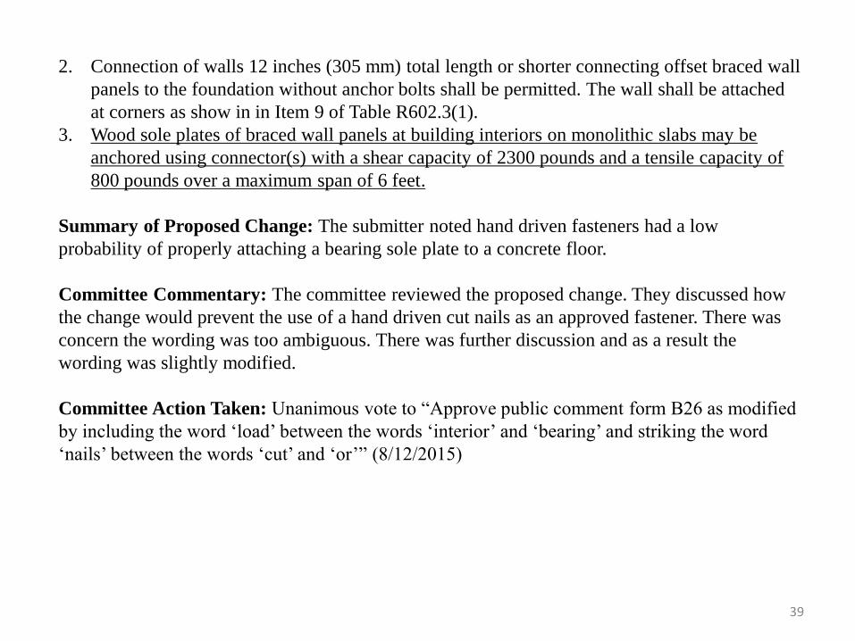
2. Connection of walls 12 inches (305 mm) total length or shorter connecting offset braced wall
panels to the foundation without anchor bolts shall be permitted. The wall shall be attached
at corners as show in in Item 9 of Table R602.3(1).
3. Wood sole plates of braced wall panels at building interiors on monolithic slabs may be
anchored using connector(s) with a shear capacity of 2300 pounds and a tensile capacity of
800 pounds over a maximum span of 6 feet.
Summary of Proposed Change: The submitter noted hand driven fasteners had a low
probability of properly attaching a bearing sole plate to a concrete floor.
Committee Commentary: The committee reviewed the proposed change. They discussed how
the change would prevent the use of a hand driven cut nails as an approved fastener. There was
concern the wording was too ambiguous. There was further discussion and as a result the
wording was slightly modified.
Committee Action Taken: Unanimous vote to “Approve public comment form B26 as modified
by including the word ‘load’ between the words ‘interior’ and ‘bearing’ and striking the word
‘nails’ between the words ‘cut’ and ‘or’” (8/12/2015)
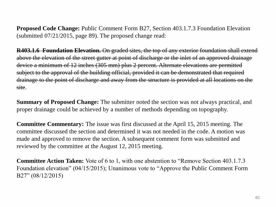
Proposed Code Change: Public Comment Form B27, Section 403.1.7.3 Foundation Elevation
(submitted 07/21/2015, page 89). The proposed change read:
R403.1.6 Foundation Elevation. On graded sites, the top of any exterior foundation shall extend
above the elevation of the street gutter at point of discharge or the inlet of an approved drainage
device a minimum of 12 inches (305 mm) plus 2 percent. Alternate elevations are permitted
subject to the approval of the building official, provided it can be demonstrated that required
drainage to the point of discharge and away from the structure is provided at all locations on the
site.
Summary of Proposed Change: The submitter noted the section was not always practical, and
proper drainage could be achieved by a number of methods depending on topography.
Committee Commentary: The issue was first discussed at the April 15, 2015 meeting. The
committee discussed the section and determined it was not needed in the code. A motion was
made and approved to remove the section. A subsequent comment form was submitted and
reviewed by the committee at the August 12, 2015 meeting.
Committee Action Taken: Vote of 6 to 1, with one abstention to “Remove Section 403.1.7.3
Foundation elevation” (04/15/2015); Unanimous vote to “Approve the Public Comment Form
B27” (08/12/2015)
40
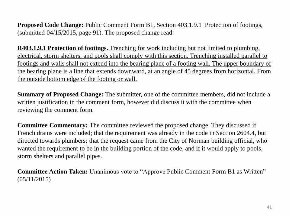
Proposed Code Change: Public Comment Form B1, Section 403.1.9.1 Protection of footings,
(submitted 04/15/2015, page 91). The proposed change read:
R403.1.9.1 Protection of footings. Trenching for work including but not limited to plumbing,
electrical, storm shelters, and pools shall comply with this section. Trenching installed parallel to
footings and walls shall not extend into the bearing plane of a footing wall. The upper boundary of
the bearing plane is a line that extends downward, at an angle of 45 degrees from horizontal. From
the outside bottom edge of the footing or wall.
Summary of Proposed Change: The submitter, one of the committee members, did not include a
written justification in the comment form, however did discuss it with the committee when
reviewing the comment form.
Committee Commentary: The committee reviewed the proposed change. They discussed if
French drains were included; that the requirement was already in the code in Section 2604.4, but
directed towards plumbers; that the request came from the City of Norman building official, who
wanted the requirement to be in the building portion of the code, and if it would apply to pools,
storm shelters and parallel pipes.
Committee Action Taken: Unanimous vote to “Approve Public Comment Form B1 as Written”
(05/11/2015)
41
42
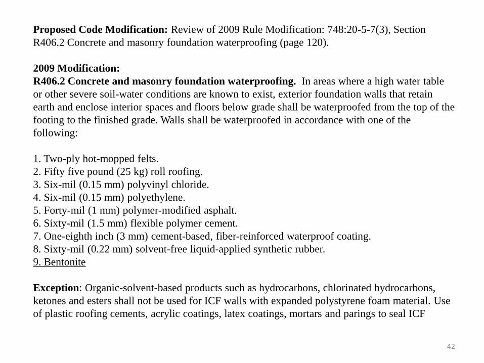
Proposed Code Modification: Review of 2009 Rule Modification: 748:20-5-7(3), Section
R406.2 Concrete and masonry foundation waterproofing (page 120).
2009 Modification:
R406.2 Concrete and masonry foundation waterproofing. In areas where a high water table
or other severe soil-water conditions are known to exist, exterior foundation walls that retain
earth and enclose interior spaces and floors below grade shall be waterproofed from the top of the
footing to the finished grade. Walls shall be waterproofed in accordance with one of the
following:
1. Two-ply hot-mopped felts.
2. Fifty five pound (25 kg) roll roofing.
3. Six-mil (0.15 mm) polyvinyl chloride.
4. Six-mil (0.15 mm) polyethylene.
5. Forty-mil (1 mm) polymer-modified asphalt.
6. Sixty-mil (1.5 mm) flexible polymer cement.
7. One-eighth inch (3 mm) cement-based, fiber-reinforced waterproof coating.
8. Sixty-mil (0.22 mm) solvent-free liquid-applied synthetic rubber.
9. Bentonite
Exception: Organic-solvent-based products such as hydrocarbons, chlorinated hydrocarbons,
ketones and esters shall not be used for ICF walls with expanded polystyrene foam material. Use
of plastic roofing cements, acrylic coatings, latex coatings, mortars and parings to seal ICF
43
walls is permitted. Cold-setting asphalt or hot asphalt shall conform to type C of ASTM D 449.
Hot asphalt shall be applied at temperature of less than 200 degrees Fahrenheit (93 degrees
Celsius).
All joints in membrane waterproofing shall be lapped and sealed with an adhesive compatible
with the membrane.
Reason for modification: The 2009 committee identified that the additional option of Bentonite
was a product commonly used in Oklahoma for waterproofing that was not prescriptively
addressed in the IRC 2009.
Committee Commentary: The committee did not review this rule change.
Committee Action Taken: No action was taken so the modification to section will carry forward
and remain in the rules.
Chapter 5 – Floors
Unanimous vote to “Approve Chapter Five as Published” (3/24/2015)
Unanimous vote to “Approve Chapter Five as Modified” (09/09/2015)
Proposed Code Change: Public Comment Forms B4 (withdrawn) and B5, Section R506.2.1 Fills
(submitted 05/08/2015 and 05/11/2015, page 149). The proposed change read:
B-5
R506.2.1- Fill. Fill material shall be free of vegetation and foreign material. The fill shall be
compacted in 8 to 12 inch lifts to ensure uniform support of the slab, and except where approved,
the fill depths shall not exceed 24 inches (610 mm) 48 inches (1220 mm) for clean sand or gravel
and 8 inches (203 mm) for earth. Where fill depths exceed 48 inches (1220 mm), the slab and
stem wall system shall be designed by accepted engineering practice/standards by a design
professional.
Summary of Proposed Change: The submitter noted, many slabs located in hilly terrain require
fill depths exceeding 24" in height. As written, Section R506.2.1 required prior approval by the
code official or forced the builder to employ crawl space construction with associated venting
problems, etc. Since some jurisdictions did not perform preconstruction plan reviews, the "where
approved" provision did not always apply. Moreover, the cost of implementing crawl space
construction was, in many cases, higher than slab construction with elevated fills.
44
Committee Commentary: The committee reviewed and discussed both comment forms. The
submitter of comment form B5 noted the differences between the two forms was that B5 allowed
an option of using sand compacted in eight to twelve inch lifts and B4 used rock and stated the
rock was self-compacting as it was installed by the builder. The committee consensus was to
utilized comment form B5 but discussed modifying it to remove the last sentence. The submitter
of comment form B4 noted he would withdraw his comment form.
Committee Action Taken: Unanimous vote to “Approve the Public Comment Form B5 as
modified” (05/11/2015)
45
Proposed Code Change: Motion in meeting on April 15, 2015, Review of 2009 Rule Modification,
and Public Comment Form B28, Section 506.2.3 Vapor retarder (submitted 07/21/2015, page 149).
The proposed change read:
2009 Rule Modification and Public Comment Form B26
506.2.3 Vapor retarder. A 6-mil (0.006 inch; 152 micrometers) polyethylene sheeting, other
industry accepted vapor retarder products installed per manufacturer specifications or approved
vapor retarder with joints lapped not less than 6 inches (152 mm) shall be placed between the
concrete floor slab and the base course or the prepared subgrade where no base course exists.
Exception: The vapor retarder is not required for the following:
1. Garages, utility buildings and other unheated accessory structures.
2. For unheated storage rooms having an area less than 70 square feet (6.5 square meters) and
carports.
3. Driveways, walks, patios and other flatwork not likely to be enclosed and heated at a later date.
4. Where approved by the building official, based on local site conditions.
Summary of Proposed Change: The submitter of B28 noted the code limited vapor retarders to
particular products while there were a number of options available on the market.
Committee Commentary: The section was first discussed in the April 15, 2015 meeting while
looking at the modification made to the 2009 adopted code. The committee determined the
modification should be brought forward and a unanimous vote to do so was taken. A comment form
was submitted with the same modification and was reviewed and voted on at the August 12, 2015
meeting.
Committee Action Taken: Unanimous vote to “Bring forward the 2009 modification”
(04/15/2015); Unanimous vote to “Approve Public Comment Form B28” (08/12/2015) 46
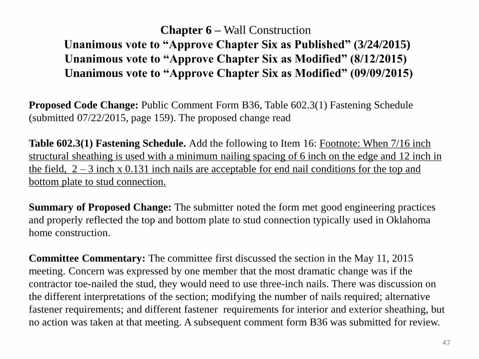
Chapter 6 – Wall Construction
Unanimous vote to “Approve Chapter Six as Published” (3/24/2015)
Unanimous vote to “Approve Chapter Six as Modified” (8/12/2015)
Unanimous vote to “Approve Chapter Six as Modified” (09/09/2015)
Proposed Code Change: Public Comment Form B36, Table 602.3(1) Fastening Schedule
(submitted 07/22/2015, page 159). The proposed change read
Table 602.3(1) Fastening Schedule. Add the following to Item 16: Footnote: When 7/16 inch
structural sheathing is used with a minimum nailing spacing of 6 inch on the edge and 12 inch in
the field, 2 – 3 inch x 0.131 inch nails are acceptable for end nail conditions for the top and
bottom plate to stud connection.
Summary of Proposed Change: The submitter noted the form met good engineering practices
and properly reflected the top and bottom plate to stud connection typically used in Oklahoma
home construction.
Committee Commentary: The committee first discussed the section in the May 11, 2015
meeting. Concern was expressed by one member that the most dramatic change was if the
contractor toe-nailed the stud, they would need to use three-inch nails. There was discussion on
the different interpretations of the section; modifying the number of nails required; alternative
fastener requirements; and different fastener requirements for interior and exterior sheathing, but
no action was taken at that meeting. A subsequent comment form B36 was submitted for review.
47
The committee reviewed comment form B36 at the August 12, 2015 meeting and determined the
modifications proposed were sufficient, however one typo was noted, the word “foe” in the
comment form should have been “for.”
Committee Action Taken: Unanimous vote to “Approve Public Comment Form B36 as modified”
(08/12/2015)
48
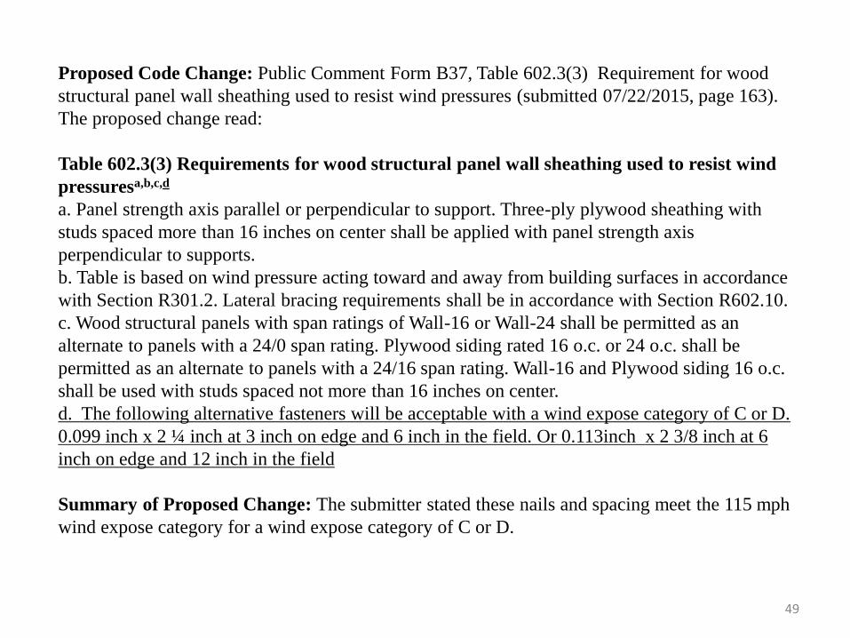
Proposed Code Change: Public Comment Form B37, Table 602.3(3) Requirement for wood
structural panel wall sheathing used to resist wind pressures (submitted 07/22/2015, page 163).
The proposed change read:
Table 602.3(3) Requirements for wood structural panel wall sheathing used to resist wind
pressuresa,b,c,d
a. Panel strength axis parallel or perpendicular to support. Three-ply plywood sheathing with
studs spaced more than 16 inches on center shall be applied with panel strength axis
perpendicular to supports.
b. Table is based on wind pressure acting toward and away from building surfaces in accordance
with Section R301.2. Lateral bracing requirements shall be in accordance with Section R602.10.
c. Wood structural panels with span ratings of Wall-16 or Wall-24 shall be permitted as an
alternate to panels with a 24/0 span rating. Plywood siding rated 16 o.c. or 24 o.c. shall be
permitted as an alternate to panels with a 24/16 span rating. Wall-16 and Plywood siding 16 o.c.
shall be used with studs spaced not more than 16 inches on center.
d. The following alternative fasteners will be acceptable with a wind expose category of C or D.
0.099 inch x 2 ¼ inch at 3 inch on edge and 6 inch in the field. Or 0.113inch x 2 3/8 inch at 6
inch on edge and 12 inch in the field
Summary of Proposed Change: The submitter stated these nails and spacing meet the 115 mph
wind expose category for a wind expose category of C or D.
49
50
Committee Commentary The committee reviewed the proposed change and noted it would allow
for alternative fasteners. There was discussion on if the fasteners were sold by local suppliers, that
the change would clean up common practice so that it was no longer illegal; and if the nails were
typically coil nails.
Committee Action Taken: Unanimous vote to “Approve Public Comment Form B37 as Written”
(08/12/2015)
51
Proposed Rule Change: Review of 2009 Rule Modification 748:20-5-9(1), Section 602.4 Interior
load-bearing walls (page 166).
2009 Rule Modification:
Section 602.4 Interior load-bearing walls. Interior load-bearing walls shall be constructed,
framed and fireblocked as specified for exterior walls. Table R602.3(5) shall be used to establish
stud spacing of walls up to 10 feet (3048 mm) high, and Table R602.3.1 shall apply to walls over
10 feet (3048 mm) high.
Summary of Change: The 2009 committee noted the commentary clarified the same information
and brought the language from the commentary into the code.
Committee Commentary: The committee reviewed the modification and determined the 2015
language should be kept and the modification deleted. No action was initially taken; however the
deletion of the 2009 modification was included as part of the electronic vote to approve the
committee presentation.
Committee Action Taken: Vote of 7 to 3 to “Delete the 2009 modification and revert to the 2015
code language” (10/19/2015).
Proposed Code Change: Public Comment Form B38, Section 602.7.5 Supports for headers
(submitted 07/22/2015, page 174). The proposed change read:
Section 602.7.5 Supports for headers. Headers shall be supported on each end with one or more
jack studs or with approved framing anchors in accordance with Table R602.7(1) or R602.7(2).
The full-height stud adjacent to each end of the header shall be end nailed to each end of the
header with four- 16d nails (3.5 inches x 0.135 inches). The minimum number of full-height studs
at each end of a header shall be in accordance with Table R602.7.5. Exception: This section only
applies for buildings with eave heights above 22 feet.
Summary of Proposed Change: The submitter stated the section was new to the code. If this
section was enforced for a standard 5 foot or 6 foot sliding glass door the builder would need to
add 3 full-height studs at each end of the header if the framing was on 16 inch stud spacing. With
a total of 6 full-height studs for this condition. He noted the change made structural sense if the
structure was greater than two stories tall.
Committee Commentary: The committee reviewed the proposed change and did not have any
discussion on it.
Committee Action Taken: Unanimous vote to “Approve Public Comment Form B38 as written”
(8/12/2015)
52
Proposed Code Change: Public Comment Form B39, Section 602.10.5 Minimum length of a
braced wall panel (submitted 07/22/2015, page 177). The proposed change read:
Section 602.10.5 Minimum length of a braced wall panel. The minimum length of a braced
wall panel shall comply with Table R602.10.5. For Methods CS-WSP and CS-SFB, the minimum
panel length shall be based on the adjacent clear opening height in accordance with Table
R602.10.5 and Figure R602.10.5. Where a panel has an opening on either side of differing heights,
the taller opening height shall be used to determine the panel length. For methods CS-PF it is
permissible to begin the portal frame at 12.5 feet from the wall line end.
Summary of Proposed Change: The submitter noted this addition allowed a single car garage to
be braced by a two car garage CS-PF, allowing the CS-PF to begin 12.5 feet from the edge of the
single car garage. He noted the change was consistent with prior codes and the simplified bracing
method which most garage designs fall within.
Committee Commentary: The committee first discussed the section at the May 11, 2015
meeting. The committee discussed when the section would have to be used, changing the
requirements, changing the wall height and simplifying the section for everyone. A comment form
was submitted and reviewed at the 8/12/2015 meeting.
Committee Action Taken: Unanimous vote to “Approve Public Comment Form B-39 as written”
(8/12/2015)
53
54
Proposed Code Change: Review of 2009 Rule Modification 748:20-5-9(2), Section 602.10.6 (in
2009) and Section 602.10.8 (in 2015, page 194), Braced wall panel connections.
2009 Modification:
Section 602.10.6 Braced wall panel connections. Braced wall panels shall be connected to the
floor framing or foundations as follows:
1. Where joists are perpendicular to a braced wall panel above or below, a rim joist, band joist or
blocking shall be provided along the entire length of the braced wall panel in accordance with
Figure R602.10.6(1). Fastening of top and bottom wall plates to framing, rim joist, band joist
and/or blocking shall be in accordance with Table R602.3(1).2.
2. Where joists are parallel to a braced wall panel above or below, a rim joist, end joist or other
parallel framing member shall be provided directly above and below the braced wall panel in
accordance with Figure R602.10.6(2). Where a parallel framing member cannot be located
directly above and below the panel, full-depth blocking at 16-inch (406 mm) spacing shall be
provided between the parallel framing members to each side of the braced wall panel in
accordance with Figure 602.10.6(2). Fastening of blocking and wall plates shall be in
accordance with Table R602.3(1) and Figure R602.10.6(2).
3. Connections of braced wall panels to concrete or masonry shall be in accordance with Section
R403.1.6.
4. Wood sole plates of braced wall panels at building interiors on monolithic slabs may be
anchored using connectors(s) with a shear capacity of 2300 pounds and a tensile capacity of
800 pounds over a maximum span of 6 feet.
55
Reason for modification: The 2009 committee established minimum values to allow for the use
of alternative anchorage systems due to the difficulty of installation of concreted imbedded J-
bolts in the interior of slabs. They noted placement of the imbedded J-bolt would need to be
within 1 inch of tolerance for a 3 1/2 inch plate; which was almost unachievable without the use
of other anchorage systems. They noted the amendment allowed for code officials and builders to
use alternative methods that met the prescribed strengths noted above when using other fastening
systems. They noted there was a lack of logic in anchorage systems used for concrete slabs and
those of wood framed foundations systems such as crawl spaces and second and third floors.
Committee Commentary: The committee did not review the 2009 rule modification.
Committee Action Taken: No action was taken, so the modification will be carried forward in
the rules. Please note, the heading change and table citations will be updated to match the 2015
code headers.
Proposed Code Change: Public Comment Form B41, Section 602.12 Simplified wall bracing
(submitted 07/22/2015, page 200). The proposed change read:
Section 602.12. Simplified wall bracing. Buildings meeting all of the conditions listed below
shall be permitted to be braced in accordance with this section as an alternate to the requirements
in Section R602.10. The entire building shall be braced in accordance with this section; the use of
other bracing provisions of Section R602.10, except as specified herein, shall not be permitted.
1. There shall be not more than three stories above the top of a concrete or masonry foundation
or basement wall. Permanent wood foundations shall not be permitted.
2. Floors shall not cantilever more than 24 inches (607 mm) beyond the foundation or bearing
wall below.
3. Wall height shall not be greater than 10 12 feet (3048 3658 mm).
4. The building shall have a roof eave-to-ridge height of 15 20 feet (4572 6096 mm) or less.
5. Exterior walls shall have gypsum board with a minimum thickness of ½ inch (12.7 mm)
installed on the interior side fastened in accordance with Table R702.3.5.
6. The structure shall be located where the ultimate design wind speed is less than or equal to
130 115 mph (58 51.4 m/s), and the exposure category is B or C.
7. The structure shall be located in Seismic Design Category A, B, or C for detached one- and
two-family dwellings or Seismic Design Category A or B for townhouses.
8. Cripple walls shall not be permitted in three-story buildings.
56
57
Summary of Proposed Change: The submitter noted in Oklahoma the design wind speed is 115
mph, not 130 mph. This change is also linked to the change to Section 602.12.2 Sheathing
materials, changing 3/8” sheathing to 7/16”. These two items allow for these increases.
Committee Commentary: The committee reviewed the proposed change and did not have any
comments.
Committee Action Taken: Unanimous vote to “Approve Public Comment Form B41 as Written”
(08/12/2015)
Proposed Code Change: Public Comment Form B40, Section 602.12.2 Sheathing materials
(submitted 07/22/2015, page 200). The proposed change read:
Section 602.12.2 Sheathing materials. The following sheathing materials installed on the
exterior side of exterior walls shall be used to construct a bracing unit as defined in Section
R602.12.3. Mixing materials is prohibited.
1. Wood structural panels with a minimum thickness of 3/8 7/16 inch (9.5 11.11 mm) fastened
in accordance with Table R602.3(3).
2. Structural fiberboard sheathing with a minimum thickness of ½ inch (12.7 mm) fastened in
accordance with Table R602.3(1).
Summary of Proposed Change: The submitter noted in Oklahoma the typical wood structural
panel is 7/16 inch. This change allows the change to 602.12 increasing the allowable wall
height and roof eave-to-ridge height increase for simplified wall bracing.
Committee Commentary: The committee reviewed the change. They commented the code
currently stated three eighths inch plywood for structural paneling and the code would go to
seven sixteenths inch, and it was just another option for use but then the simplified method
could not be used.
Committee Action Taken: Unanimous vote to “Approve as Written”(08/12/2015)
58
Chapter 7 – Wall Covering
Unanimous vote to “Approve Chapter Seven as Published” (3/24/2015)
Unanimous vote to “Approve Chapter Seven as Modified” (09/09/2015)
Proposed Code Change: Review of 2009 Rule Modification 748:20-5-10 and Public Comment
Form B19, Section 703.4 Flashing (submitted 06/26/2015, page 349). The proposed change read:
2009 Rule Modification
Approved corrosion-resistant flashing shall be applied shingle-fashion in a manner to prevent
entry of water into the wall cavity or penetration of water to the building structural framing
components. 6-mil polyethylene sheeting is an approved corrosion-resistant flashing when not
exposed to UV rays. Self-adhered membranes use as flashing shall comply with AAMA 711. The
flashing shall extend to the surface of the exterior wall finish. Approved corrosion-resistant
flashings shall be installed at all of the following locations:
1. Exterior window and door openings. Flashing at exterior window and door openings shall
extend to the surface of the exterior wall finish or to the water-resistive barrier for subsequent
drainage.
2. At the intersection of chimneys or other masonry construction with frame or stucco walls, with
projecting lips on both sides under stucco copings.
3. Under and at the ends of masonry, wood or metal copings and sills
4. Continuously above all projecting wood trim.
5. Where exterior porches, decks or stairs attach to a wall or floor assembly of wood-frame
construction.
59
60
6. At wall or roof intersections
7. At built-in gutters.
Reason for modification: The 2009 committee noted in rural areas where there had been no
residential construction code, finding "approval" for a product may be difficult. The committee was
trying to provide guidance for one approved flashing product for walls. The committee noted the
intent was to allow for the 6-mil polyethylene to be used behind the finished facade materials of a
building where metal flashings would be unable to be used and create continuity of the flashing
system. They noted a product that could be utilized to create a path to the exterior of the building,
if required. The committee noted the modification did not allow for the use of the product on roof
and wall intersections or other areas that were exposed to UV light.
B19
Section 703.4 Flashing. Approved corrosion-resistant flashing shall be applied shingle-fashion in
a manner to prevent entry of water into the wall cavity or penetration of water to the building
structural framing components. 6-mil polyethylene sheathing is an approved corrosion-resistant
flashing when not exposed to UV rays. Self-adhered membranes used as flashing shall comply with
AAMA 711. Fluid-applied membranes used as flashing in exterior walls shall comply with AAMA
714. The flashing shall extend to the surface of the exterior wall finish. Approved corrosion-
resistant flashings shall be installed at all of the following locations:
1. Exterior window and door openings. Flashing at exterior window and door openings shall
extend to the surface of the exterior wall finish or to the water-resistive barrier, barrier
complying with Section 703.2 for subsequent drainage. Mechanically attached flexible
flashings shall comply with AAMA 712. Flashing at exterior window and door openings shall
be installed in accordance with one or more of the following:
1.1 The fenestration manufacturer’s installation and flashing instructions, or for applications not
addressed in the fenestration manufacturer’s instructions, in accordance with the flashing
manufacturer’s instructions. Where flashing instructions or details are not provided flashing to
be installed per 1.2, 1.3, 1.4 or pan flashing shall be installed at the sill of exterior window and
door openings. Pan flashing shall be sealed or sloped in such a manner as to direct
water to the surface of the exterior wall finish or to the water-resistive barrier for subsequent
drainage. Openings using pan flashing shall incorporate flashing or protection at the head and
sides.
1.2 In accordance with the flashing design or method of a registered design professional.
1.3 In accordance with other approved methods or standard industry practices.
1.4 Flashings above doors are not required where it is unlikely to have rain or other
moisture accumulation occur above the door.
2. At the intersection of chimneys or other masonry construction with frame or stucco walls, with
projecting lips on both sides under stucco copings.
3. Under and at the ends of masonry, wood or metal copings and sills.
4. Continuously above all projecting wood trim.
5. Where exterior porches, decks or stairs attach to a wall or floor assembly of wood-frame
construction.
6. At wall and roof intersections.
7. At built-in gutters.
61
Summary of Proposed Change: The submitter noted the committee wanted to incorporate
several historically approved practices regarding flashing into the code. There are many effective
methods to properly flash around doors and windows and the current wording in the code does not
address many of the door and window products used locally. These amendments allow for
currently used materials and industry practices used in single family construction in Oklahoma.
Committee Commentary: The committee discussed B19 noting it added 6-mil polyethylene
sheathing as an approved corrosion resistant flashing when not exposed to UV rays and it added
more verbiage to Section 703.4. They noted it was done to address other design methods to protect
doors from the elements.
Committee Action Taken: Unanimous vote to “Approve Public Comment Form B19 as Written”
(07/08/2015)
62
Proposed Code Change: Public Comment Form B20, Figure 703.8 Typical Masonry Veneer Wall
Details (submitted 06/26/2015, page 353). The proposed change read:
Figure 703.8. Typical Masonry Veneer Wall Details -Add new footnotes f. and g. to Figure
R703.8. The proposed change read as follows:
f. Flashing to be done per section R703.4 or in accordance with a design from a registered design
professional or in accordance with other approved methods or standard industry practices.
g. Flashing depicted under sill and above windows are not required with windows that have nailing
flanges for their primary attachment. Flange type windows should be counter flashed into the
weather resistant barrier or installed per R703.4.
Footnote should be placed after the title - FIGURE R703.8 TYPICAL MASONRY WALL
DETAILSe,f,g
Summary of Proposed Change: The submitter noted the committee wanted to incorporate several
historically approved practices regarding flashing into the code. The codes details depict windows
not typically seen in this market in single family construction. Most windows in single family
construction having nailing flanges which can be flashed over to accomplish the requirements of
section R703.4. In order to give builders and installers a better idea of the requirements the
committee felt the amendment was appropriate.
Committee Commentary: The committee reviewed the comment form and felt it was a good
modification.
Committee Action Taken: Unanimous vote to “Approve Public Comment Form B20 as Written”
(07/08/2015) 63
Proposed Code Change: Public Comment Form B21, Figure 703.8.2.1, Exterior Masonry Veneer
Support by Steel Angles and Figure 703.8.2.2, Exterior Masonry Veneer Support by Roof
Members (submitted 06/26/2015, page 356). The proposed addition requested the same footnote
to be added to both figures and read:
Figure 703.8.2.1 Exterior Masonry Veneer Support by Steel Angles and Figure 703.8.2.2
Exterior Masonry Veneer Support by Roof Members
a. Flashing to be done per section R703.4 or in accordance with a design from a registered design
professional or in accordance with other approved methods or standard industry practices.
Footnote should be placed after “FIGURE R703.8.2.1 EXTERIOR MASONRY VENEER
SUPPORT BY STEEL ANGLES” a and Footnote should be placed after “FIGURE R703.8.2.2
EXTERIOR MASONRY VENEER SUPPORT BY ROOF MEMBERS”a
Summary of Proposed Change: The submitter stated the committee wanted to incorporate
several historically approved practices regarding flashing into the code. The flashing details as
depicted in the details are not readily constructible methods. The verbiage in the code text and
detail only allowed for the exact methodology shown in the details while current flashing methods
are as effective and more practical installations.
Committee Commentary: The committee reviewed the comment form. There was concern the
form was a duplicate of B20, however the submitter noted it was not - it addressed different
figures, and explained the form gave builders more flexibility to build.
Committee Action Taken: Unanimous vote to “Approve as Written” (07/08/2015)
64
65
Proposed Code Change: Public Comment Form B62, Section 703.8.3.1, Allowable span
(Submitted 9/8/2015, page 357). The proposed change read:
R703.8.3.1 Allowable span. The allowable span shall not exceed the values set forth in Table
R703.8.3.1. Additionally, a 3” x 3” x 3/16” steel angle 6’-0” long may be used to support 3
vertical feet of masonry veneer, and a 3” x 3” x 3/16” steel angle 5’-0” long may be used to
support 4’-3” vertical feet of masonry veneer.
Summary of Proposed Change: The submitter stated the change would provide guidance to
builders using this typical (for Oklahoma) lintel.
Committee Commentary: The committee reviewed the proposed form. One of the members
noted they ran an analysis and it would work fine.
Committee Action Taken: Unanimous vote to “Approve Public Comment Form B62 as Written”
(9/9/2015)
Chapter 8 – Roof Ceiling Construction
Unanimous vote to “Approve Chapter Eight as Published” (3/24/2015)
Unanimous vote to “Approve Chapter Eight as Modified” (09/09/2015)
Proposed Code Change: Review of Rule Modification 748:20-5-11(1) and Public Comment
Form B34, Section 801.3 Roof drainage (submitted 07/22/2015, page 365). The proposed change
read:
2009 Modification and Public Comment Form B34
R801.3 Roof drainage. In areas where expansive or collapsible soils are known to exist, all
dwellings shall have a controlled method of water disposal from roofs that will collect and
discharge roof drainage to the ground surface at least 5 feet (1524 mm) from foundation walls or
to an approved drainage system.
Summary of Proposed Change: The 2009 committee felt like surface drainage was addressed in
Section R401.3 Drainage with an established method for how surface water is to be directed
away from a structure by grading with minimum slopes and swales to divert water away from the
structure. The committee felt the section was poorly written and prone to misinterpretation,
especially the portion stating "where expansive or collapsible soils are known to exist". They
noted that language could apply to all of the State of Oklahoma or it may only include areas with
soils that show a high plasticity index. They further noted that information was not "common"
knowledge throughout the State and felt Section 401.3 adequately handled the issue. The
submitter of B34 noted, the reason for the change was as detailed with the 2009 IRC amendment
modifications by the OUBCC.
66
67
Committee Commentary: The committee first reviewed the section in the July 8, 2015 meeting.
They determined the modification was still applicable and made a motion to bring forward the
2009 modification. A subsequent comment form was then submitted and voted on at a following
meeting.
Committee Action Taken: Unanimous vote to “Bring forward the 2009 rule modification”
(7/8/2015); Unanimous vote to “Approve Public Comment Form B34 as Written” (08/12/2015)
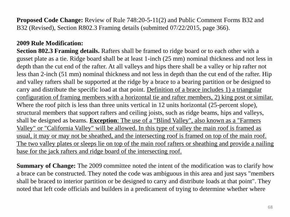
Proposed Code Change: Review of Rule 748:20-5-11(2) and Public Comment Forms B32 and
B32 (Revised), Section R802.3 Framing details (submitted 07/22/2015, page 366).
2009 Rule Modification:
Section 802.3 Framing details. Rafters shall be framed to ridge board or to each other with a
gusset plate as a tie. Ridge board shall be at least 1-inch (25 mm) nominal thickness and not less in
depth than the cut end of the rafter. At all valleys and hips there shall be a valley or hip rafter not
less than 2-inch (51 mm) nominal thickness and not less in depth than the cut end of the rafter. Hip
and valley rafters shall be supported at the ridge by a brace to a bearing partition or be designed to
carry and distribute the specific load at that point. Definition of a brace includes 1) a triangular
configuration of framing members with a horizontal tie and rafter members, 2) king post or similar.
Where the roof pitch is less than three units vertical in 12 units horizontal (25-percent slope),
structural members that support rafters and ceiling joists, such as ridge beams, hips and valleys,
shall be designed as beams. Exception: The use of a "Blind Valley", also known as a "Farmers
Valley" or "California Valley" will be allowed. In this type of valley the main roof is framed as
usual, it may or may not be sheathed, and the intersecting roof is framed on top of the main roof.
The two valley plates or sleeps lie on top of the main roof rafters or sheathing and provide a nailing
base for the jack rafters and ridge board of the intersecting roof.
Summary of Change: The 2009 committee noted the intent of the modification was to clarify how
a brace can be constructed. They noted the code was ambiguous in this area and just says "members
shall be braced to interior partition or be designed to carry and distribute loads at that point". They
noted that left code officials and builders in a predicament of trying to determine whether where
68
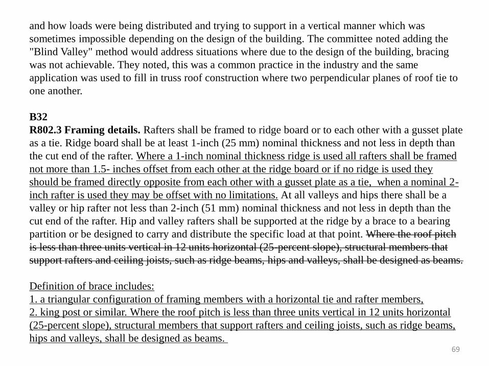
69
and how loads were being distributed and trying to support in a vertical manner which was
sometimes impossible depending on the design of the building. The committee noted adding the
"Blind Valley" method would address situations where due to the design of the building, bracing
was not achievable. They noted, this was a common practice in the industry and the same
application was used to fill in truss roof construction where two perpendicular planes of roof tie to
one another.
B32
R802.3 Framing details. Rafters shall be framed to ridge board or to each other with a gusset plate
as a tie. Ridge board shall be at least 1-inch (25 mm) nominal thickness and not less in depth than
the cut end of the rafter. Where a 1-inch nominal thickness ridge is used all rafters shall be framed
not more than 1.5- inches offset from each other at the ridge board or if no ridge is used they
should be framed directly opposite from each other with a gusset plate as a tie, when a nominal 2-
inch rafter is used they may be offset with no limitations. At all valleys and hips there shall be a
valley or hip rafter not less than 2-inch (51 mm) nominal thickness and not less in depth than the
cut end of the rafter. Hip and valley rafters shall be supported at the ridge by a brace to a bearing
partition or be designed to carry and distribute the specific load at that point. Where the roof pitch
is less than three units vertical in 12 units horizontal (25-percent slope), structural members that
support rafters and ceiling joists, such as ridge beams, hips and valleys, shall be designed as beams.
Definition of brace includes:
1. a triangular configuration of framing members with a horizontal tie and rafter members,
2. king post or similar. Where the roof pitch is less than three units vertical in 12 units horizontal
(25-percent slope), structural members that support rafters and ceiling joists, such as ridge beams,
hips and valleys, shall be designed as beams.
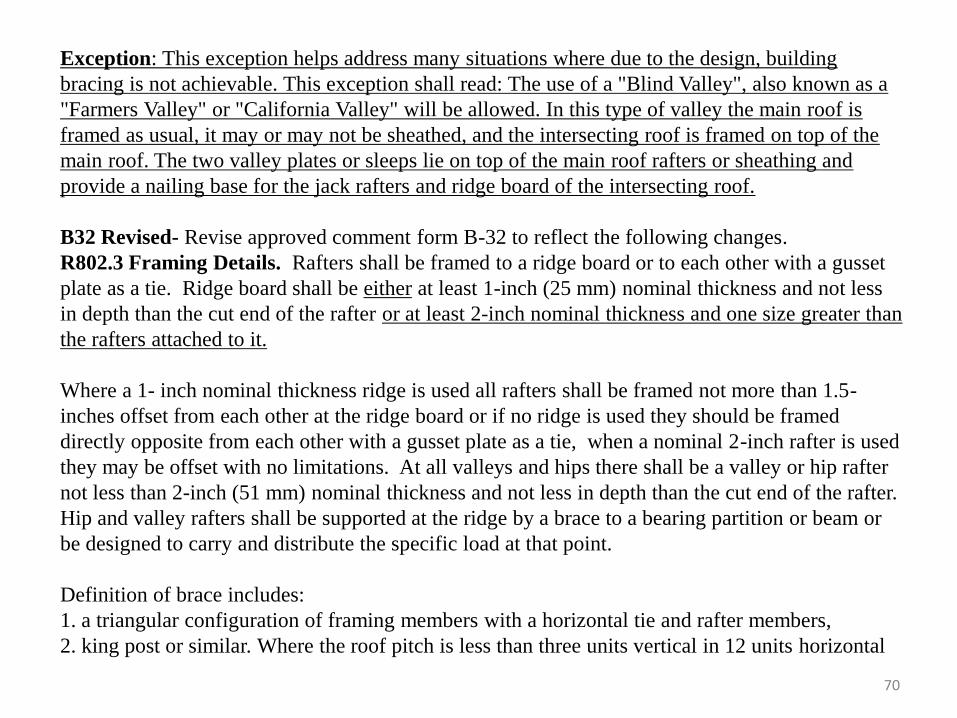
Exception: This exception helps address many situations where due to the design, building
bracing is not achievable. This exception shall read: The use of a "Blind Valley", also known as a
"Farmers Valley" or "California Valley" will be allowed. In this type of valley the main roof is
framed as usual, it may or may not be sheathed, and the intersecting roof is framed on top of the
main roof. The two valley plates or sleeps lie on top of the main roof rafters or sheathing and
provide a nailing base for the jack rafters and ridge board of the intersecting roof.
B32 Revised- Revise approved comment form B-32 to reflect the following changes.
R802.3 Framing Details. Rafters shall be framed to a ridge board or to each other with a gusset
plate as a tie. Ridge board shall be either at least 1-inch (25 mm) nominal thickness and not less
in depth than the cut end of the rafter or at least 2-inch nominal thickness and one size greater than
the rafters attached to it.
Where a 1- inch nominal thickness ridge is used all rafters shall be framed not more than 1.5-
inches offset from each other at the ridge board or if no ridge is used they should be framed
directly opposite from each other with a gusset plate as a tie, when a nominal 2-inch rafter is used
they may be offset with no limitations. At all valleys and hips there shall be a valley or hip rafter
not less than 2-inch (51 mm) nominal thickness and not less in depth than the cut end of the rafter.
Hip and valley rafters shall be supported at the ridge by a brace to a bearing partition or beam or
be designed to carry and distribute the specific load at that point.
Definition of brace includes:
1. a triangular configuration of framing members with a horizontal tie and rafter members,
2. king post or similar. Where the roof pitch is less than three units vertical in 12 units horizontal
70
(25-percent slope), structural members that support rafters and ceiling joists, such as ridge beams,
hips and valleys, shall be designed as beams.
Exception: This exception helps address many situations where due to the design, building bracing
is not achievable. This exception shall read: The use of a "Blind Valley", also known as a "Farmers
Valley" or "California Valley" will be allowed. In this type of valley the main roof is framed as
usual, it may or may not be sheathed, and the intersecting roof is framed on top of the main roof.
The two valley plates or sleeps lie on top of the main roof rafters or sheathing and provide a nailing
base for the jack rafters and ridge board of the intersecting roof.
Summary of Proposed Change: The submitter of the original B32 form stated: This section of the
code has been modified for several reasons. The 2015 IRC required that all rafters be offset from
each other by no more than 1.5”. As almost all framing involves at least 2” nominal members
there has been no historical evidence that ridges are deflecting with rafters being offset. The code
is being amended to allow the practice of rafters being offset from each other as quite often rafters
on one side of the ridge are at 24” spacing and the other side might be at 16” spacing.
Additionally the code has not historically provided for a definition of a brace. With a myriad of
methods to properly brace roof framing members the committee felt this clarification might
eliminate some ambiguous interpretations in the building community with what is considered
proper bracing.
The IRC has also not provided or acknowledged framing methods which have been historically
constructed in Oklahoma and many surrounding states. The practice of framing what is often
referred to as a Blind Valley, Farmers Valley, or California Valley has been accepted by most all
jurisdictions. The amendment provides basis for builders and jurisdictions to continue to accept
the practice. 71
The same submitter sent in a revised B32 due to discussion during the initial review. He stated: In
discussions regarding roof framing it was brought up in committee that at times the ends of the
common rafters were a greater depth than the ridge they attached to because of the higher sloped
roof pitch cuts. With these connections still having plenty of bearing surface and nominal 2x
ridges being used on these connections it was agreed that so long as the ridge was of a greater
nominal depth than the attaching rafter small projections by the common rafter should not be
problematic.
Committee Commentary: When the committee first reviewed the section, they noted the only
thing changed was the inch and a half offset. There was discussion on the definition of a “brace.”
Concern was expressed that the modifications made to the section could be a problem later in the
chapter. The committee determined not to bring forward the entire 2009 Rule Modification,
however they did chose to vote to bring forward the definition of a “brace” from that
modification. A comment form was created to modify the section, but there was concern with the
wording and that it would cause issues. The comment form was tabled and the submitter noted he
would revise the form. The revised form was reviewed and approved at the September 9, 2015
meeting.
Committee Action Taken: Motion to bring forward the definition of a “brace” from the 2009 rule
modification (7/8/2015); Vote to “Approve the Revised Public Comment Form B32 as Written”
(9/9/2015)
72
Proposed Code Change: Public Comment Form B22, Section 802.3.1 Ceiling joist and rafter
connections (submitted 07/15/2015, page 366). The proposed change read:
R802.3.1 Ceiling joist and rafter connections. Ceiling joists and rafters shall be nailed to each
other every 4 feet (1219mm) on center in accordance with Table R802.5.1(9), and the rafter shall
be nailed to the top wall plate in accordance with Table R602.3(1). Ceiling joists shall be
continuous or securely joined in accordance with Table R802.5.1(9) where they meet over interior
partitions and are nailed to adjacent rafters to provide a continuous tie across the building when
such joists are parallel to the rafters.
Where ceiling joists are not connected to the rafters at the top wall plate, joists connected
higher in the attic shall be installed as rafters ties, or rafter ties shall be installed to provide a
continuous tie. Where ceiling joists are not parallel to rafters, rafter ties shall be installed every 4
feet (1219 mm) on center. Rafter ties shall be a minimum of 2 inches by 4 inches (51 mm by 102
mm) (nominal), installed in accordance with the connection requirements in Table R802.5.1(9), or
connections of equivalent capacities shall be provided. Where ceiling joists or rafter ties are not
provided, the ridge formed by there rafters shall be supported by a wall, beam or girder designed
constructed in accordance with accepted engineering practice this code.
Collar ties or ridge straps to resist wind uplift shall be connected in the upper third of the
attic space in accordance with Table R602.3(1).
Collar ties shall be not less than a minimum of 1 inch by 4 inches (25mm by 102mm)
(nominal), spaced not more than 4 feet (1219mm) on center.
73
Summary of Proposed Change: The submitter noted the Technical Committee agreed these
changes would make the code reflect current framing practices.
Committee Commentary: The committee reviewed the public comment form and there were no
changes or modifications.
Committee Action Taken: Unanimous vote to “Approve Public Comment Form B22 as Written”
(08/12/2015)
74
75
Summary of Proposed Change: Public Comment Forms B63 and B66, Section 802.5 Allowable
rafter spans (submitted 9/8/2015, page 367). The proposed changes read:
B63
802.5 Allowable rafter spans. Spans for rafters shall be in accordance with Tables R802.5.1(1)
through R802.5.1(8). For other grades and species and for other loading conditions, refer to the
AWC STJR. The span of each rafter shall be measured along the horizontal projection of the
rafter. Exception: Collar Ties. Installation of collar ties to reduce the span of rafters is permitted
as shown in Figure R802.5.1. Collar ties shall be sized not less than the required size of the rafters
they are connected to.
Summary of Proposed Change: The submitter stated the change was to provide guidance to
Oklahoma builders using this typical (for Oklahoma) framing system.
B66
802.5 Allowable rafter spans. Spans for rafters shall be in accordance with Tables R802.5.1(1)
through R802.5.1(8). For other grades and species and for other loading conditions, refer to the
AWC STJR. The span of each rafter shall be measured along the horizontal projection of the
rafter. The tabulated rafter spans in Tables R802.5.1(1) through R802.5.1(8) assume ceiling joists
are located at the bottom of the attic space or some other method of resisting the outward push of
the rafters on the bearing walls, such as rafter ties, is provided at that location. Where ceiling
joists or rafter ties are located higher in the attic space, the rafter spans in these tables shall be
multiplied by the following rafter reduction factors: Where ceiling joists or rafter ties are located
76
at one third the span of the rafter the adjustment factor is 0.67, at one quarter the span of the rafter
the adjustment factor is 0.76, at one fifth the span of the rafter the adjustment factor is 0.83, at one
sixth the span of the rafter the adjustment factor is 0.90 and at two fifteenth of the rafter or less,
there is no need for adjusting the rafter capacity.
Summary of Change: The submitter noted the change was to provide guidance to Oklahoma
builders framing rafters above the top sill of the wall system. This is a typical framing method to
increase the height of the room. It also happens to increase the loading on the rafter. The tables
point this out in footnote a, but it has not been widely or properly used. The description above,
converting the vertical measuring into horizontal span lengths is much simpler for an inspector to
check.
Committee Commentary: The committee discussed the proposed changes, noting the language
for B66 was from a footnote, brought into the code to give inspectors an alternate way of looking
at the allowable rafter spans and that the change would alter the way the rafters were measured.
They discussed if the collar tie would be the point of support or a point of inflection on the
binding of the rafter and if it should be an exception.
Committee Action Taken: Unanimous vote to “Approve Public Comment Form B63 as written”;
Unanimous vote to “Approve Public Comment Form B66 as written” (9/9/2015)
Proposed Code Change: Review of rule modification 748:20-5-11(3) and Public Comment Form
B33, Section 802.5.1 Purlins (submitted 07/22/2015, page 367). The proposed changes read:
2009 Rule Modification
Installation of purlins to reduce the span of rafters is permitted as shown in Figure R802.5.1
Purlins shall be sized no less than the required size of the rafters that they support. Purlins shall be
continuous and shall be supported by 2-inch by 4-inch (51 mm by 102 mm) braces installed to
bearing walls at a slope not less than 45 degrees from the horizontal. The braces shall be spaced
not more than 4 feet (1219 mm) on center and the unbraced length of braces shall not exceed 8
feet (2438 mm). Braces may be spaced not more than 6 feet (1829 mm) on center if 1) the purlin
brace is 2-inch by 6-inch (51 mm by 153 mm); 2). purlins shall be sized one nominal size larger
than the rafter they support; and 3). Unbraced length of braces shall not exceed 8 feet (2438 mm).
Summary of Change: The 2009 committee proposed the modification as an alternative method
for how purlins were braced. They noted in many cases due design and interior partition wall
layouts, the increased spacing of the braces in a purlin system may be required. They noted the
exception allowed for the spacing of bracing supporting the purlin to be increased from 4 feet to 6
feet if the three conditions were met.
B33
Section 802.5.1– Purlins. Installation of purlins to reduce the span of rafters is permitted as
shown in Figure 802.5.1. Purlins shall be sized not less than the required size of the rafters that
they support. Purlins shall be continuous and shall be supported by 2-inch by 4-inch (51 mm by
102 mm) braces installed to bearing walls at a slope not less than 45 degrees (0.79 rad) from the
horizontal. The braces shall be spaced not more than 4 feet (1219 mm) on center and the
77
78
unbraced length of braces shall not exceed 8 feet (2438 mm). Exception: Braces may be spaced
not more than 6 feet (1829 mm) on center if: 1. the purlin brace is 2-inch by 6-inch (51 mm by
153 mm) 2. Purlins shall be sized one nominal size larger than the rafter they support, and 3.
unbraced length of braces shall not exceed 8 feet (2438 mm).
Summary of Proposed Change: The submitter noted the IRC only made provisions for purlins
to be supported at 4’ on center. Adding with modern home designs that had wider spans and
more open floor plans made it a challenging requirement. The exception allowed for spacing of
supports at 6 foot on center so long as certain framing details are followed.
Committee Commentary: The committee first reviewed the section at the July 8, 2015 meeting.
They noted there was additional language in the 2015 code that included braces installed to
bearing walls at a slope no less than 45 degrees from horizontal. The committee voted to bring
forward the 2009 modification. A subsequent comment form was then submitted, reviewed and
approved at the August 12, 2015 meeting.
Committee Action Taken: Unanimous vote “Bring forward the 2009 Code Modification”
(7/8/2015); Unanimous vote to “Approve Public Comment Form B33 as Written” (08/12/2015)
79
Proposed Code Change: Public Comment Form B52, Section R802.7.1.2, Ceiling joist taper cut.
(submitted 9/4/15, page 388). The proposed change read:
R802.7.1.2 Ceiling joist taper cut. Taper cuts at the ends of the ceiling joist shall not exceed one-
fourth the depth of the member in accordance with Figure R802.7.1.2. Exception: For ceiling joist
not carrying more than 25 lb. tributary load (Limited Attic Storage) then taper cut at end of joist
maybe able to be increased to D/2.
Summary of Proposed Change: The submitter stated the code was prescriptive to address a
potential 3-story structure with joist supporting all levels so taper cut had to be severely limited.
On single story structures that have 2 x 10 or 2 x 12 joists with less than 8/12 pitches this
requirement would be unachievable. So putting a maximum tributary load on joist system and
increasing taper cut end of joist is reasonable and practical way to address this issue.
Committee Commentary: The committee discussed the proposed change, noting historically
speaking, builders did not build the types of homes the section was addressing.
Committee Action Taken: Unanimous vote to “Approve Public Comment Form B52 as Written”
(9/9/2015)
80
Chapter 9 – Roof Assemblies
Unanimous vote to “Approve Chapter Nine as Modified” (09/09/2015)
Proposed Code Change: Public Comment Forms B15, B23, B29, and B30, Section R905.2.1
Sheathing Requirements (submitted 06/24/2015, 07/15/2015, 07/21/2015 and 07/21/2015). The
proposed changes read:
B15
R905.2.1 Sheathing Requirements. Asphalt shingles shall be fastened to solidly sheathed decks
in accordance to Section R803 or to the asphalt shingles manufacturer’s installation instructions.
Summary of Proposed Change: The submitter stated there seemed to be confusion with the
section, some think the word sheathed means a structural panel. Sheathed is not defined in the
code so one must refer to Webster Dictionary (a tight fitting covering). This interpretation is being
spread throughout the state indicating that sawed lumber decking does not conform to code and
during reroofs all sawed lumber decking is required to be replaced with a structural panel. Section
R803 allows sawed lumber as a roof decking or roof sheathing.
81
B-23
905.2.1 Sheathing requirements. Asphalt shingles shall be fastened to solidly sheathed decks.
Plank decking wider than 6 inches is not considered a solid deck and does not meet manufacturer's
specifications.
Summary of Proposed Change: The submitter noted the use of plank decking required detailed
supervision to insure that it did not have gapes that were too wide or narrow. He noted the gaps
often prevented the roofer from installing the shingle in the correct nail line specified by the
manufacturer. He noted sheet decking took that out of the equation. He added wrapping and
cupping of plank decking was frequently a source of leakage and the practice of plank decking
was nearly obsolete.
B-29
R905.2.1 Sheathing requirements. Asphalt shingles shall be fastened to solidly sheathed decks
consisting of the minimum of 3/8 inch or 7/16 inch plywood or OSB decking. Existing structures
with skip decking/resawn 1x6 or 1x8 are required to be covered with the aforementioned plywood
or OSB.
Summary of Proposed Change: The submitter noted the practice of 1x6 or 1x8 decking is almost
obsolete and requested the change so as to not void warranties from shingle manufacturers if there
were leaks due to the buckling issues associated with the practice.
82
B-30
R905.2.1 Sheathing requirements. Asphalt shingles shall be fastened to solidly sheathed decks.
The submitter did not submit any proposed language, rather asked for clarification language to be
added to the section to define “Plank Decking, Spaced Decking, and Skip Decking” and that the
language include anything “wider than 6 inches is not considered a solid decking which fails to
meet manufacture’s specifications.” He also requested language to say “any dimensional lumber
not installed using the tongue and grove application or with gaps greater than 1/8 inch would fail
to meet the manufacture's specifications.”
Summary of Proposed Change. The submitter noted the application of asphalt shingles
regardless of the manufacturer is consistent with the process. Nailed with the “nail strip” meeting
the manufactures specifications. There was little to no difference in the manufacturing process of
Laminated Shingles” between the top five manufactures, GAF, Certain Teed, Owens Corning,
Malarkey, and IKO represented more than 80% of the total US business. He noted there was one
consistent element in the application process between all five companies, was “OSB or Plywood
or nominal tongue and groove lumber”, indicating 4x8 fully sheathed decking or non-gapped
tongue and groove lumber. He noted the expansion and contraction of spaced decking within the
seasons continually put homeowners at risk for warping and cupping. This roof system failure
created an unprecedented number of roofing issues and claims against manufactures, contractors
and insurance companies.
83
Committee Commentary: The committee reviewed public comment form B15 at the July 8,
2015 meeting. They discussed the change would direct the user back to Section 803 for decking
requirements; the industry issues with one by six (1 x 6) and one by eight (1 x 8) decking; a GAF
advisory bulletin regarding wood planking and if used it would not void warranties, and how
jurisdictions could interpret the code differently.
The committee reviewed comment forms B23, B29 and B30 at the August 12, 2015 meeting,
noting all three comment forms addressed the same section. They discussed shingle manufacturer
installation requirements; intent of B23’s change was to prevent overlay of OSB over sawed
lumber decking; securing the deck nailing correctly; and the modifications proposed in the other
two comment forms.
Committee Action Taken: Unanimous vote to “Approve Public Comment Form B15”
(7/8/2015); Unanimous vote to “Deny Public Comment Form B23”; Unanimous vote to “Deny
Public Comment Form B29”; and Unanimous Vote to “Deny Public Comment Form B30”
(8/12/2015)
84
Proposed Code Change: Public Comment Form B47, Section 905.2.8.5 Drip edge (submitted
8/21/15, page 418). The proposed change read:
R905.2.8.5 Drip edge. A drip edge shall be provided at eaves and raked edges of shingle roofs.
Adjacent segments of drip edge shall be overlapped not less than 2 inches (51 mm). Drip edges
shall extend not less than ¼ inch (6.4 mm) below the roof sheathing and extend up back onto the
roof deck not less than 2 inches (51 mm). Drip edges shall be mechanically fastened to the roof
deck at not more than 12 inches 9305 mm) o.c. with fasteners as specified in Section R905.2.5.
Underlayment shall be installed over the drip edge along eaves and under the underlayment along
rake edges. Exception: If a nominal 1” x 2” shingle mold is used, attached to the fascia and the
starter course of shingles is extended a minimum of ¼” and not more than 1” then a metal drip
edge is not required.
Summary of Proposed Change: The submitter note it was common across the state and country
for shingle molds and starter shingles to be used instead of a metal drip edge. Flashing of the
fascia board is achieved by felt paper being installed to the outer edge of the roof and further by
extending the starter course of shingles an additional ¼” to ¾” from the fascia which keeps the
water running off the fascia board which is the intent of installing a metal drip edge. This method
also addresses aesthetic issues with metal drip edges which often deform due to thermal expansion
creating a wavy look on the edge of the roof.
Committee Commentary: The committee reviewed the comment form and felt it was a good
idea. They did note a typo using the word “Mould” instead of “Mold.”
Committee Action Taken: Unanimous vote to “Approve Public Comment Form B47 as Modified
to correct the wording typo” (9/9/15)
85
Proposed Code Change: Public Comment Forms B17 (withdrawn) and B45, Section 908.3.1.1
Roof re-cover (submitted 6/25/15 and 8/18/15, page 426). The proposed change read:
908.3.1.1 A roof re-cover shall not be permitted where any of the following conditions occur:
1. Where the existing roof or roof covering is water soaked or has deteriorated to the point that
the existing roof or roof covering is not adequate as a base for additional roofing.
2. Where the existing roof covering is slate, clay , cement or asbestos-cement tile.
3. Where the existing roof has two or more applications of any type of roof covering.
4. Where the existing roof has one or more applications of asphalt shingles additional
applications of asphalt shingles shall not be permitted.
Summary of Proposed Change: The submitter noted the proposal was a result of a discussion
during the August 12, 2015 meeting.
Committee Commentary: The committee discussed the section at the August 12, 2015 meeting
when language was proposed with form B17 that was withdrawn. Comment form B45 was the
revised version. One of the committee members stated he had contacted several shingle
manufacturers and they did not recommend laying down three tabs, but it was allowed by them.
Committee Action Taken: Unanimous vote to “Approve Public Comment Form B45 as Written”
(9/9/2015)
Chapter 10 – Chimneys and Fireplaces
Unanimous vote to “Approve Chapter Ten as Modified” (09/09/2015)
Proposed Code Change: Public Comment Form B46, Section 1005.7 Factory-built chimney
offsets (submitted 8/18/2015, page 436). The proposed change read:
Section 1005.7 Factory-built chimney offsets. Where a factory-built chimney assembly
incorporates offsets, no part of the chimney shall be at an angle of more than 30 degrees (0.52 rad)
from vertical at any point in the assembly and the chimney assembly shall not include more than
four elbows. Exception: Where chimneys are part of a listed and labeled Factory Built Fireplace
they can be installed in accordance with the fireplace and chimney manufacturer’s installation
instructions.
Summary of Proposed Change: The submitter noted it appeared the intent of the section was to
regulate factory-built chimneys being installed on masonry site built fireplaces. But the wording
was ambiguous enough to suggest it would apply to manufactured fireplaces which quite often
have offsets of more than 30 degrees.
Committee Commentary: The committee reviewed the form and felt it was a good idea.
Committee Action Taken: Unanimous vote to “Approve Public Comment Form B46 as Written”
(9/9/2015)
86
Chapter 11 – Energy Efficiency
Unanimous vote to “Approve Chapter Eleven as Modified” (09/09/2015)
Proposed Code Change: Public Comment Form B35, Chapter 11 Energy Efficiency (submitted
07/22/2015, page 437). The proposed change read:
Chapter 11 Energy Efficiency – Move to an appendix.
Summary of Proposed Change: Move the entire chapter to an appendix and leave the adoption
of the chapter to the local Authority Having Jurisdiction.
Committee Commentary: The committee reviewed the comment form and asked if the
submitter was present to speak to the committee. The submitter was not present. There were
several other comment forms that dealt with Chapter Eleven and the committee determined the
chapter should stay in the code.
Committee Action Taken: Unanimous vote to “ Deny the Public Comment Form B35”
(08/12/2015)
87
Proposed Code Change: Public Comment Forms B42 and B43, Chapter 11 Energy Efficiency
(submitted 08/03/2015 and 08/06/2015, page 437). The two proposals were extensive
modifications of Chapter Eleven. Please see attached public comment forms for complete details.
B42:
Delete all of Chapter Eleven from the 2015 International Residential Code® and replace with
language from the 2009 and 2012 Editions of the International Residential Code®.
Summary of Proposed Change (B42): The submitter noted his proposal would use some
language from the 2009 and 2012 Chapter Eleven, Energy Efficiency. The submitter felt the code
needed to be better defined and more stringent to be effective for Oklahoma. Oklahoma citizens
deserve an efficient built home.
B43:
Delete Chapter Eleven from the 2015 IRC in its entirety. Replace with the 2009 Chapter Eleven
language with some modifications. Additionally, as part of this proposal were changes to Chapter
2 definitions and Chapter 3 to provide for continuity between the 2009 IRC language and the 2015
IRC.
(Note: Modifications in B43 address 2009 Rule Changes 748:20-5-12(1), Section N1101.9
Certificate; 748:20-5-12(2), Section N1102.4.3 Fireplaces; 748:20-5-12(4) Section N1103.2.2
Sealing; and 748:20-5-12(5) Section N1103.8.3 Pool covers).
88
Summary of Proposed Change (B43): The submitter noted the amendment effectively brought
forward the 2009 IRC Chapter Eleven on Energy Efficiency and in some instances strengthened it.
He stated the 2009 IRC Chapter Eleven has proven to be a very effective, quality and prescriptive
code for Oklahoma. Many of the requirements in the 2015 IRC will be real cost additions with
limited proven evidence for reducing energy in our climate zone.
Committee Commentary: The submitter of B43 addressed the committee. He stated his form
brought forward all of the modifications made by the 2009 committee with a few exceptions. He
noted his proposal provides for a more prescriptive code and would align the Chapter with current
construction materials and methods in use and his changes would not add a lot of cost to the
builder or the consumer. The submitter of B42 addressed the committee and explained some of his
key points were to eliminate a visual inspection, increase duct tightness testing (in a year from
now) and testing for air tightness in two years (blower door test). He stated he combined the 2009
and 2012 language. He added a recent newspaper article which indicated OG&E would be
increasing rates from 15 to 19 percent over the next few years and his changes would help combat
those costs. He touched on a need to make statewide enforcement of the requirements a priority.
The committee discussed the proposed changes with the submitters and several others in the
audience. They discussed several items within the chapter, including Duct Testing; can lights, CFLs
and florescent bulbs; the ability to enforce the code in small jurisdictions; wording changes;
simulations used to come up with projected savings; HERS scores and ratings; the use of liquid
mastic; cost increase to implement the changes; protection of the consumer; and focusing on the
elements of installation instead of the maintenance of the home. There was further discussion on
B43 at the September meeting.
89
90
Committee Action Taken:
August 12, 2015 meeting: A vote to “Approve Public Comment Form B42 as the baseline to
start the Chapter Eleven discussion” failed due to a lack of a second. A motion was made to
“Deny Public Comment Form B42 as the baseline to start the discussion of Chapter Eleven” but a
vote was not taken. A motion was made to “Approve Public Comment Form B43 as written” was
made but no vote was taken. A unanimous vote was made to “Approve Public Comment Form
B43 as the baseline to start discussion of Chapter Eleven”; a second Unanimous vote to
“Approve Public Comment Form B43 was made to “Approve Public Comment Form B43 as the
base line to start from on discussing chapter eleven with the possibility of modification to the
comment form”
September 9, 2015 meeting: Unanimous vote to “Use Public Comment Form B43 as the
version the Committee should review”, Unanimous vote to “Approve Public Comment Form
B43”
NOTE: Both comment forms B42 and B43 sought to replace the current chapter with the previous 2009
version. For rules, the 2015 chapter numbering (which was very different from the 2009 version), needed to be
kept in line so there is a marked up version of Chapter Eleven with all the modifications approved in B43 made
in legislative format in the appropriate sections in the 2015 version is behind this presentation, as well as
comment forms B43 and B42.
91
Proposed Code Change: Public Comment Form B53, Chapter Eleven, Energy Efficiency
(submitted 9/4/2015, page 437). The proposed change read:
Chapter 11 Energy Efficiency: Retain all language IRC 2015 Chapter Eleven, review sections of
chapter individually and revise as deemed necessary.
Summary of Proposed Change: The submitter stated the Residential Electrical Technical
Committee felt that PCF43 with its amendments did not address all the sections of IRC 2015
Chapter Eleven adequately. Second, the committee felt that deleting Chapter Eleven was not the
correct action, that Chapter Eleven text should be revised, deleted, added to, or deleted with
substitution. Once the IRC 2015 Chapter was deleted, could it be replaced? Placed in “Reserve”
would retain the IRC 2015 Chapter.
Committee Commentary: The committee reviewed the comment form noting that comment
form B43 had already been voted on and questioning if that vote needed to be rescinded before
addressing comment form B53. They discussed the versions submitted to be reviewed and the
conversion of the changes into rules format. Further, the 2015 IRC Chapter Eleven had already
been reviewed and discussed at great length during the August 12, 2015 meeting.
Committee Action Taken: Vote of 8 to 1 to “Deny Public Comment Form B53” (9/9/2015)
92
Proposed Code Change: Public Comment Form B57, Section N1101.6, Defined Terms, High-
efficacy lamps (submitted 9/4/2015, page 438). The proposed change read:
HIGH-EFFICACY LAMPS. Compact fluorescent lamps, Light Emitting Diode (L.E.D.) type
lamps, T-8 or smaller diameter linear fluorescent lamps, or lamps with a minimum efficacy of:
1. 60 lumens per watt for lamps over 40 watts;
2. 50 lumens per watt for lamps over 15 watts to 40 watts;
3. 40 lumens per watt for lamps 15 watts or less.
Summary of Proposed Change: The submitter noted the change was provided to give code
language more clarity, without referring to items 1 through 3. PCF-E12 was submitted to the
Electrical Technical Committee. The proposed change was discussed and passed unanimously.
The wording submitted was exactly the same as PCF E8. LED lamps were not readily available to
consumers when the 2009 IRC was published. Dimmable compact fluorescent lamps were not
readily available either. Both are now readily available at electrical wholesale, home improvement
stores and the internet.
Committee Commentary: The committee reviewed the proposed change. They discussed with
the submitter that the location of the change should be in Chapter Two of the code with the rest of
the definitions, because with the version adopted by the Committee, there were no longer any
definitions listed in Chapter Eleven, they were collated with all definitions in Chapter Two.
Committee Action Taken: Vote of 8 to 1 to “Approve Public Comment Form B57 as modified by
changing the reference to the Chapter Two definition” (9/9/2015)
93
Proposed Code Change: Public Comment Form B48, Table 1102.1.2 Insulation and Fenestration
Requirements by Componenta (submitted 9/1/2015, page 456). The proposed change read:
TABLE N1102.1.2 INSULATION AND FENESTRATION REQUIREMENTS BY
COMPONENTa
Add footnote L to state:
l. If foundation/slab insulation is used and slab ledge exists, ½” insulation in Vertical position is
allowed as thermal break between slab edge and foundation wall so that slab can still bear on
horizontal ledge.
Summary of Proposed Change: The submitter stated due to foundation designs that are non
monolithic often have a slab ledge of an 1-1/2” which is formed on the stem wall for slab to bear
and often steel is extended from the Stem wall into slab. Meeting the R-5 requirement of slab
insulation (1”) would not leave sufficient bearing width. This will have minimal impact on
reducing that 3-1/2” area around the foundation by only having R-3.
Committee Commentary: The committee reviewed the form and thought it was a good idea.
Committee Action Taken: Unanimous vote to “Approve Public Comment Form B48 as Written”
(9/9/2015)
94
Proposed Code Change: Public Comment Form B68 (B43 Revision 1), Table N1102.1.2
Insulation and Fenestration Requirements by Componenta (submitted 9/8/2015, page 456). The
proposed change read:
TABLE N1102.1 INSULATION AND FENSTRATION REQUIREMENTS BY
COMPONENTa
Modify language on the approved comment form B43. Add footnote “m” behind the word
Component in the table Heading as follows: “…by COMPONENTa,m”
On Table N1102.1 add a new footnote M to state:
m. In addition to the requirements in Table N1102.1 two one of the following improvements are
required:
1. Fenestration U Factors to be .35
2. Wood Frame Wall R-Value to be R15
3. Slab R-Value and Depth to be 5,2 ft.
4. Ceiling R-Value to be R38
5. In section N1104.1 a minimum of 75 percent of the lamps permanently installed luminaries
shall be high-efficacy lamps.
Exception: If duct testing is performed and passed in accordance with N1103.2.2 by either the
Post-construction test or Rough-in test no further upgrade is required from the Values in Table
N1102.1.
95
Summary of Proposed Change: The submitter noted after modeling and evaluating the approved
Public Comment Form B43, it was determined that the proposal did not quite meet the equivalency
with the 2009 IECC. Being proposed in this amendment is a flexible method builders can model
their homes while not readily effecting the cost and design. Some of the items for consideration
were increased U-Values for windows from .40 to .35. .35 windows or better are already on the
market and have been for awhile. Window manufacturers have largely responded to the national
codes and are providing products in excess of this standard. R-15 wall insulation is often achieved
by installations where the walls have blown-in insulation. In the case of batt insulation most all
manufacturers do produce these batts and they can be used in a 3.5” wall. In markets that require
R-15 the product is readily available. Slab insulation provides a good form of insulation creating a
thermal break associate with exterior stem and slabs and is a cost effective measure to install. All
of these options provide a code that meets or very slightly exceeds equivalency with the 2009
IECC but it must be noted that the biggest impact, in efficiency, comes from duct testing. Duct
testing is twice as effective as any of the other two options put together. That is why the exception
is written as is.
Committee Commentary: The form was initially labeled as B-43 revised, but at the request of the
Chairman, the form was renumbered to B68. The committee reviewed the comment form and noted
the requirements would make the code more stringent than the current code. They determined a
section reference should be added to item to reference N1102.2.8 for installation details.
Committee Action Taken: Unanimous vote to “Approve comment form B68 as modified by
adding to Item 3 a reference N1102.2.8 for installation details” (9/9/2015); Unanimous vote to
“Modify B68 by changing the word “two” to “one” and striking through Item 5 due to the approval
of Public Comment Form B56” (9/9/2015)
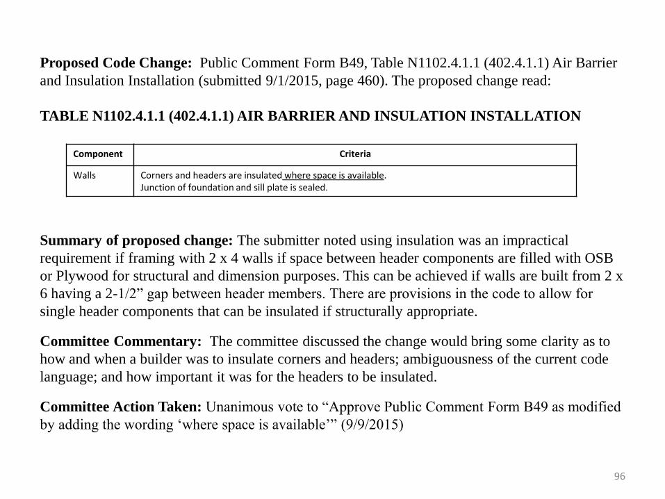
96
Proposed Code Change: Public Comment Form B49, Table N1102.4.1.1 (402.4.1.1) Air Barrier
and Insulation Installation (submitted 9/1/2015, page 460). The proposed change read:
TABLE N1102.4.1.1 (402.4.1.1) AIR BARRIER AND INSULATION INSTALLATION
Component Criteria
Walls Corners and headers are insulated where space is available. Junction of foundation and sill plate is sealed.
Summary of proposed change: The submitter noted using insulation was an impractical
requirement if framing with 2 x 4 walls if space between header components are filled with OSB
or Plywood for structural and dimension purposes. This can be achieved if walls are built from 2 x
6 having a 2-1/2” gap between header members. There are provisions in the code to allow for
single header components that can be insulated if structurally appropriate.
Committee Commentary: The committee discussed the change would bring some clarity as to
how and when a builder was to insulate corners and headers; ambiguousness of the current code
language; and how important it was for the headers to be insulated.
Committee Action Taken: Unanimous vote to “Approve Public Comment Form B49 as modified
by adding the wording ‘where space is available’” (9/9/2015)
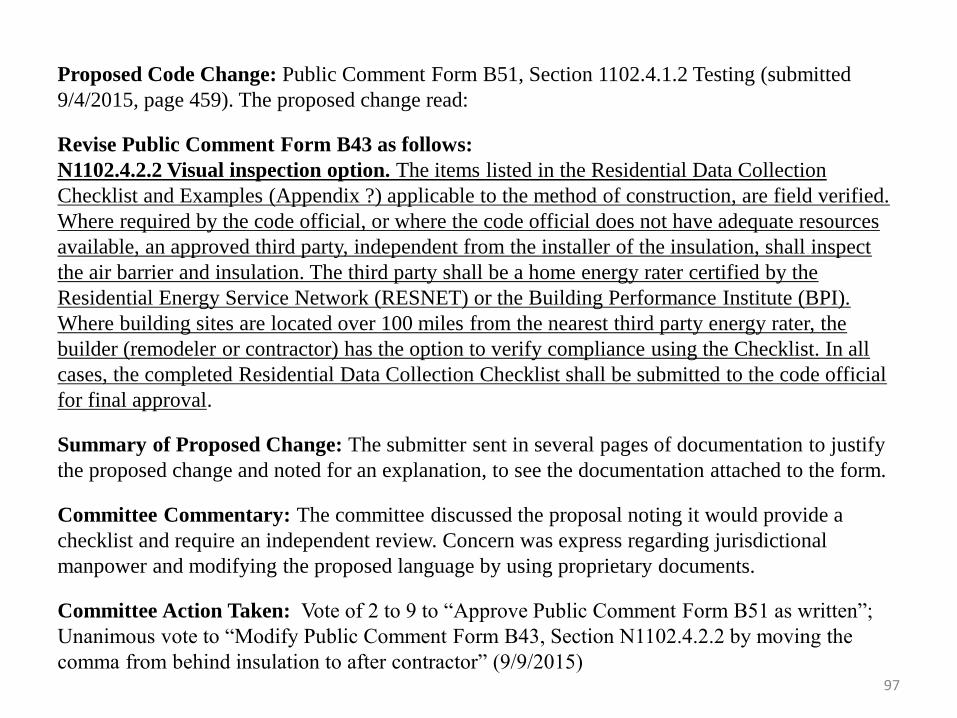
97
Proposed Code Change: Public Comment Form B51, Section 1102.4.1.2 Testing (submitted
9/4/2015, page 459). The proposed change read:
Revise Public Comment Form B43 as follows:
N1102.4.2.2 Visual inspection option. The items listed in the Residential Data Collection
Checklist and Examples (Appendix ?) applicable to the method of construction, are field verified.
Where required by the code official, or where the code official does not have adequate resources
available, an approved third party, independent from the installer of the insulation, shall inspect
the air barrier and insulation. The third party shall be a home energy rater certified by the
Residential Energy Service Network (RESNET) or the Building Performance Institute (BPI).
Where building sites are located over 100 miles from the nearest third party energy rater, the
builder (remodeler or contractor) has the option to verify compliance using the Checklist. In all
cases, the completed Residential Data Collection Checklist shall be submitted to the code official
for final approval.
Summary of Proposed Change: The submitter sent in several pages of documentation to justify
the proposed change and noted for an explanation, to see the documentation attached to the form.
Committee Commentary: The committee discussed the proposal noting it would provide a
checklist and require an independent review. Concern was express regarding jurisdictional
manpower and modifying the proposed language by using proprietary documents.
Committee Action Taken: Vote of 2 to 9 to “Approve Public Comment Form B51 as written”;
Unanimous vote to “Modify Public Comment Form B43, Section N1102.4.2.2 by moving the
comma from behind insulation to after contractor” (9/9/2015)
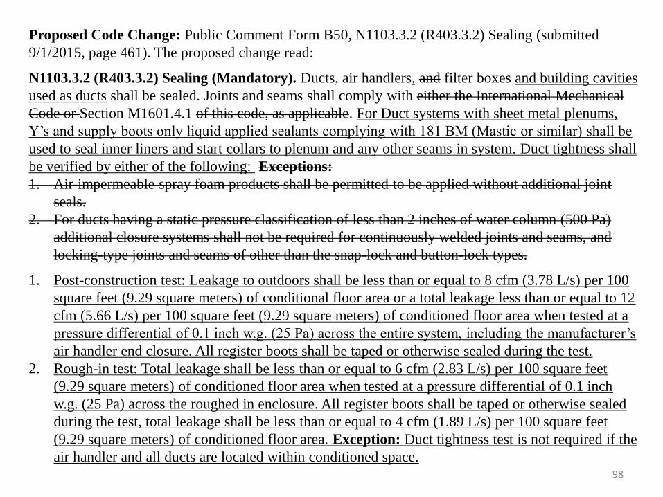
98
Proposed Code Change: Public Comment Form B50, N1103.3.2 (R403.3.2) Sealing (submitted
9/1/2015, page 461). The proposed change read:
N1103.3.2 (R403.3.2) Sealing (Mandatory). Ducts, air handlers, and filter boxes and building cavities
used as ducts shall be sealed. Joints and seams shall comply with either the International Mechanical
Code or Section M1601.4.1 of this code, as applicable. For Duct systems with sheet metal plenums,
Y’s and supply boots only liquid applied sealants complying with 181 BM (Mastic or similar) shall be
used to seal inner liners and start collars to plenum and any other seams in system. Duct tightness shall
be verified by either of the following: Exceptions:
1. Air-impermeable spray foam products shall be permitted to be applied without additional joint
seals.
2. For ducts having a static pressure classification of less than 2 inches of water column (500 Pa)
additional closure systems shall not be required for continuously welded joints and seams, and
locking-type joints and seams of other than the snap-lock and button-lock types.
1. Post-construction test: Leakage to outdoors shall be less than or equal to 8 cfm (3.78 L/s) per 100
square feet (9.29 square meters) of conditional floor area or a total leakage less than or equal to 12
cfm (5.66 L/s) per 100 square feet (9.29 square meters) of conditioned floor area when tested at a
pressure differential of 0.1 inch w.g. (25 Pa) across the entire system, including the manufacturer’s
air handler end closure. All register boots shall be taped or otherwise sealed during the test.
2. Rough-in test: Total leakage shall be less than or equal to 6 cfm (2.83 L/s) per 100 square feet
(9.29 square meters) of conditioned floor area when tested at a pressure differential of 0.1 inch
w.g. (25 Pa) across the roughed in enclosure. All register boots shall be taped or otherwise sealed
during the test, total leakage shall be less than or equal to 4 cfm (1.89 L/s) per 100 square feet
(9.29 square meters) of conditioned floor area. Exception: Duct tightness test is not required if the
air handler and all ducts are located within conditioned space.
99
Summary of Proposed Change: The submitter stated the text was being added to require a
liquid sealant of metal connections of the supply and return duct distribution system because it is
the only effective and long lasting way to ensure the HVAC system duct leakage can be reduced to
acceptable levels to comply with the 2009 IRC Chapter 11. It has been found that duct tapes over
time lose their adhesiveness in the attic space where exposed to high temperatures and are difficult
to get wrapped properly with the inner liner of the insulated ducts. Cost impacts are minimal if
compared to the proper installation using duct tape products and proper execution is rarely
achieved in use of those products and life expectancy of duct tapes is not acceptable
Committee Commentary: The committee discussed the proposed change. During the discussion
they determined the language needed to be slightly modified.
COMMITTEE Action Taken: Unanimous vote to “Approve Public Comment Form B50 as
Modified by adding the wording ‘comply with 181 BM’ after the word ‘sealants’” (9/9/2015)
COMMISSION ACTION TAKEN: The Commission voted at the October 20, 2015 meeting to
“Accept public comment form B50, adding the wording “or equivalent method” behind the
wording “(mastic or similar)”; adding visual inspection as an option on Number three as shown in
the FGMP presentation; removing the exception on item number two and listing it under all three
options; striking the word “either” and adding the word “one” in its place and including the
wording “UL” before the wording “181 BM.”
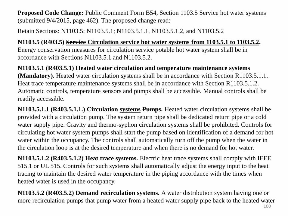
100
Proposed Code Change: Public Comment Form B54, Section 1103.5 Service hot water systems
(submitted 9/4/2015, page 462). The proposed change read:
Retain Sections: N1103.5; N1103.5.1; N1103.5.1.1, N1103.5.1.2, and N1103.5.2
N1103.5 (R403.5) Service Circulation service hot water systems from 1103.5.1 to 1103.5.2.
Energy conservation measures for circulation service potable hot water system shall be in
accordance with Sections N1103.5.1 and N1103.5.2.
N1103.5.1 (R403.5.1) Heated water circulation and temperature maintenance systems
(Mandatory). Heated water circulation systems shall be in accordance with Section R1103.5.1.1.
Heat trace temperature maintenance systems shall be in accordance with Section R1103.5.1.2.
Automatic controls, temperature sensors and pumps shall be accessible. Manual controls shall be
readily accessible.
N1103.5.1.1 (R403.5.1.1.) Circulation systems Pumps. Heated water circulation systems shall be
provided with a circulation pump. The system return pipe shall be dedicated return pipe or a cold
water supply pipe. Gravity and thermo-syphon circulation systems shall be prohibited. Controls for
circulating hot water system pumps shall start the pump based on identification of a demand for hot
water within the occupancy. The controls shall automatically turn off the pump when the water in
the circulation loop is at the desired temperature and when there is no demand for hot water.
N1103.5.1.2 (R403.5.1.2) Heat trace systems. Electric heat trace systems shall comply with IEEE
515.1 or UL 515. Controls for such systems shall automatically adjust the energy input to the heat
tracing to maintain the desired water temperature in the piping accordance with the times when
heated water is used in the occupancy.
N1103.5.2 (R403.5.2) Demand recirculation systems. A water distribution system having one or
more recirculation pumps that pump water from a heated water supply pipe back to the heated water
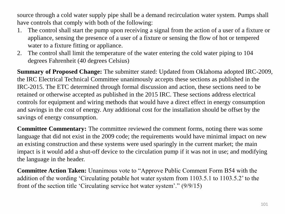
101
source through a cold water supply pipe shall be a demand recirculation water system. Pumps shall
have controls that comply with both of the following:
1. The control shall start the pump upon receiving a signal from the action of a user of a fixture or
appliance, sensing the presence of a user of a fixture or sensing the flow of hot or tempered
water to a fixture fitting or appliance.
2. The control shall limit the temperature of the water entering the cold water piping to 104
degrees Fahrenheit (40 degrees Celsius)
Summary of Proposed Change: The submitter stated: Updated from Oklahoma adopted IRC-2009,
the IRC Electrical Technical Committee unanimously accepts these sections as published in the
IRC-2015. The ETC determined through formal discussion and action, these sections need to be
retained or otherwise accepted as published in the 2015 IRC. These sections address electrical
controls for equipment and wiring methods that would have a direct effect in energy consumption
and savings in the cost of energy. Any additional cost for the installation should be offset by the
savings of energy consumption.
Committee Commentary: The committee reviewed the comment forms, noting there was some
language that did not exist in the 2009 code; the requirements would have minimal impact on new
an existing construction and these systems were used sparingly in the current market; the main
impact is it would add a shut-off device to the circulation pump if it was not in use; and modifying
the language in the header.
Committee Action Taken: Unanimous vote to “Approve Public Comment Form B54 with the
addition of the wording ‘Circulating potable hot water system from 1103.5.1 to 1103.5.2’ to the
front of the section title ‘Circulating service hot water system’.” (9/9/15)
102
Commission Action Taken: The Commission voted at the October 20, 2015 meeting to accept
public comment form B54 as modified by underlining “circulation service potable” in the second
line of N1103.5; Changing in Section N1103.5.3 ¾ nominal to 1 inch nominal pipe; and required
an R3 Value instead of an R2 value in Section N1103.4.
Proposed Code Change: Review of Rule Modification 748:20-5-12(3), Section N1103.1.1,
Programmable thermostat (page 461).
2009 Modification read as follows:
Section N1103.1.1 Programmable thermostat. Where the primary heating system is a forced-air
furnace, at least one thermostat per dwelling unit shall be capable of controlling the heating and
cooling system on a daily schedule to maintain different temperature set points at different times of the
day. This thermostat shall include the capability to set back or temporarily operate the system to
maintain zone temperatures down to 55 degrees Fahrenheit (13 degrees Celsius) or up to 85 degrees
Fahrenheit (29 degrees Celsius). The thermostat shall initially be programed with a heating
temperature set point no higher than 70 degrees Fahrenheit (21 degrees Celsius) and a cooling
temperature set point no lower than 78 degrees Fahrenheit (26 degrees Celsius).
Reason for Modification: The 2009 committee felt a programmable thermostat was something that
could be added by the homeowner at any time and shouldn't be a requirement. They noted that they can
actually have a negative savings especially in the summer as a truly efficient system sized correctly for
the home can only recover two degrees an hour. They recommended keeping the structure at one
temperature that was maintained at that setting consistently for the best energy efficiency.
Committee Commentary: The committee reviewed the 2009 modification and discussed the
improper use of thermostats; the customers choice to have one installed; if it was an industry
requirement to educate the public on the proper cost efficient way to operate the thermostat, indoor air
quality, and other technologies available.
Committee Action Taken: Vote of 3 to 6 to “Bring forward the 2009 rule modification which struck
the requirement for programmable thermostats” (08/12/2015) (Note: The 2009 modification will be stricken based on the vote above) 103
Proposed Code Change: Motion made during meeting on Section N1104.1 (R404.1), Electrical
Lighting equipment (Mandatory) (page 463). The proposed change read:
N1104.1 (R404.1) Lighting equipment (Mandatory). Not less than 75 percent of the lamps in
permanently installed lighting fixtures luminaires shall be high-efficacy lamps or not less than 75
percent of the permanently installed lighting fixtures luminaires shall contain only high-efficacy
lamps. Exception: Low-voltage lighting.
Summary of Proposed Change: To Align the 2015 IRC® Code language with the NEC® code
language.
Committee Commentary: During the discussion over Chapter Eleven, Mr. Ross Barrick
introduced himself as the Commission Liaison for the Electrical Technical Committee. He noted he
wanted to address Section N1104.1. He stated the electrical committee voted on some wording
changes. He noted in the section the words “lighting fixtures” was changed to “luminaires.” He
noted the language was changed in either 2005 or 2008 NEC so the committee would be bringing
the code into alignment with the NEC. Mr. Barrick stated in regards to Mr. Clark’s comment form
over the exception for can lights and recess lights. He stated he agreed with Mr. Morgan, the
expectation was not needed due to the different options that were now available. He stated with
using the CFL’s and the LED’s there was more light output with less heat.
Committee Action Taken: Unanimous vote to “Approve the Motion to change the wording
lighting fixtures to luminaires throughout Chapter Eleven” (08/12/2015)
104
Proposed Code Change: Review of Rule Modification 748:20-5-12(6), Motion made during
meeting and Public Comment Form B56 Section N1104.1 Lighting equipment (Mandatory)
(submitted 9/4/2015, page 463):
2009 Modification:
Section N1104.1 Lighting equipment. A minimum of 50 percent of the lamps in permanently
installed lighting fixtures shall be high-efficacy lamps. Exception: Can or recessed lights are
exempt from this section of the code.
Summary of 2009 Change: The 2009 modification was made because the committee noted no
one made a high-efficiency lamp with reasonable durability and lighting characteristics, for
example dimmable with reasonable longevity.
B56
N1104.1 Lighting equipment (Mandatory). Not less than 75 percent of the lamps in
permanently installed lighting fixtures luminaries shall be high-efficacy lamps or not less than75
percent of the permanently installed lighting fixtures luminaries shall contain only high-efficacy
lamps. Exception: Low-voltage lighting.
Summary of Proposed Change: The submitter noted the Residential Electrical Technical
Committee discussed and unanimously approved PCF E11, an exact duplicate of this comment
form. The term lighting fixture was replaced with “luminaire” in the 2008 NFPA-70, National
Electrical Code, the source of IRC-2015 Chapters 34 through 43, addressed in the introduction to
Chapter 34. The ETC discussed the percentage ratio factor, Public Law 110-140 – Dec. 19, 2007
US Energy Independence and Security Act of 2007, lamp manufacturer's product data, and current
types and styles of lamps available to the consumer. The ETC concluded that the 75 percent 105
106
requirement appears to be in alignment with US EISA-20-7, the requirements manufacturers are
meeting, the numerous energy savings programs electric utilities and the lamps that are readily
available to consumers.
Committee Commentary: The committee discussed the removal of the exception for can
lighting from the requirements. They noted removing the exception would mean can lights could
now be used as the market was changing and the installation of any incandescent lights would be
outlawed and it would really self-correct. The committee discussed B56 at the September 9, 2015
meeting. They discussed how the market had now responded to having lots of options for high
efficacy lighting and the products were not as cost prohibitive as they were in the past.
Committee Action Taken: Unanimous vote to “Remove the exception for can lights proposed by
the electrical committee” (08/12/2015); Unanimous vote to “Approve Public Comment Form B56
as Written” (9/9/2015)
107
Proposed Code Change: Public Comment Form B58, Section N1107.4 Compliance (submitted
9/4/2015, page 469). The proposed change read:
Retain Section N1107.4 (R501.4) Compliance.
N1107.4 (R501.4) Compliance. Alterations, repairs, additions, and changes of occupancy to, or
relocation of, existing buildings and structures shall comply with the provisions for alterations,
repairs, additions, and changes of occupancy or relation respectively in this code, and the
International Building Code, International Fire Code, International Fuel Gas Code, International
Mechanical Code, International Plumbing Code, International Property Maintenance Code,
International Private Sewage Disposal Code and NFPA 70.
Summary of Proposed Change: The submitter stated: Updated form Oklahoma adopted IRC-
2009, the IRC-Electrical Technical Committee unanimously accepts this section as published in
the 2015 IRC. The ETC determined, through formal discussion and action, this section needs to be
retained or otherwise accepted as published in the IRC-2015. This section recognizes NFPA 70
National Electrical Code and lists the additional ICC codes.
Committee Commentary: The committee discussed that leaving the section stricken as
previously approved would not change the code books listed in Chapter One and did not have any
impact on the referenced code books.
Committee Action Taken: Unanimous vote to “Deny Public Comment Form B58” (9/9/2015)

108
Proposed Code Change: Public Comment Form B59, Section 1108.1.1.4 (R502.1.1.4) Lighting
(submitted 9/4/2015, page 469). The proposed change read:
Retain Section N1108.1.1.4 (R502.1.1.4) Lighting.
N1108.1.1.4 (R502.1.14) Lighting. New lighting systems that are part of the addition shall
comply with Section N1104.1.
Summary of Proposed Change: The submitter stated: Updated from Oklahoma adopted IRC-
2009, the IRC-Electrical Technical Committee unanimously accepts this section as published in
the 2015 IRC. The ETC determined, through formal discussion and action, this section needs to be
retained or otherwise accepted as published in the IRC-2015. This section recognizes IRC-2015
Chapter Eleven, Section N1104.1 Lighting equipment requirements for high-efficacy.
Committee Commentary: The committee reviewed the form and felt the issue had been
previously addressed.
Committee Action Taken: Unanimous vote to “Deny Public Comment Form B59” (9/9/2015)
109
Proposed Code Change: Public Comment Form B60, Section 1109.1.1.4 (R503.1.4) Lighting
(submitted 9/4/2015, page 470). The proposed change read:
Retain Section N1109.1.1.4 (R503.1.4) Lighting.
N1109.1.1.4 (R503.1.4) Lighting. New lighting systems that are part of the alteration shall
comply with Section N1104.1. Exception: Alterations that replace less than 50 percent of the
luminaires in a space, provided that such alterations do not increase the installed interior lighting
power.
Summary of Proposed Change: The submitter stated: Updated from Oklahoma adopted IRC-
2009, the IRC-Electrical Technical Committee unanimously accepts this section as published in
the 2015 IRC. The ETC determined, through formal discussion and action, this section needs to
be retained or otherwise accepted as published in the IRC-2015. This section recognizes IRC-
2015 Chapter Eleven, Section N1104.1 Lighting equipment requirements for high-efficacy. This
section also provides an exception for alterations with replacement luminaires.
Committee Commentary: The committee reviewed the form, discussed alterations, and
determined that the form should not be approved. The committee felt the code and the adopted
amendements adequately addressed the items.
Committee Action Taken: Unanimous vote to “Deny Public Comment Form B60” (9/9/2015)
110
Proposed Code Change: Public Comment Form B61, Section 1110.2 (R504.2) Application
(submitted 9/4/2015, page 470). The proposed change read:
Retain Section N1110.2 (R504.2) Application
N1110.2 (R504.2) Application. For the purposes of this code, the following shall be considered
repairs:
1. Glass-only replacement in an existing sash and frame.
2. Roof repairs.
3. Repairs where only the bulb and/or ballast within the existing luminaires in a space are
replaced provided that the replacement does not increase the installed interior lighting power.
Summary of Proposed Change: The submitter stated: Updated from Oklahoma adopted IRC-
2009, the IRC-Electrical Technical Committee unanimously accepts this section as published in
the 2015 IRC. The ETC determined, through formal discussion and action, this section needs to
be retained or otherwise accepted as published in the IRC-2015. This section provides a
definition for “repairs” as relating to repairs to luminaires and their energy efficiency addressed
in IRC-2015, Chapter Eleven, Section N1104.1.
Committee Commentary: The committee reviewed the form and felt the issue had been
previously addressed. The committee felt the code and adopted amendments adequately
addressed the items.
Committee Action Taken: Unanimous vote to “Deny Public Comment Form B61” (9/9/2015)
111
Proposed Code Change: Motion from March 9, 2015 meeting and Public Comment Forms B2
and B14, Section R326 Swimming Pools, Spas and Hot Tubs (submitted 04/27/2015 and
05/27/2015). The proposed changes read:
As part of the proposed modifications to Chapter Eleven, the submitter of B43 made the
following changes to Chapter Two. For the details on comment form B43, please see
information on the Summary of Change and Committee Discussion on tiles 88 to 90 of this
presentation.
2009 Appendix G (to be added to the newly created Appendix in the 2015 code for Swimming
Pools, Spas and Hot Tubs:
Appendix V
SWIMMING POOLS, SPAS AND HOT TUBS
(The provisions contained in this appendix are not mandatory unless specifically referenced in
the adopting ordinance.)
Section AV101 General
AV101.1 General. The provisions of this appendix shall control the design and construction of
swimming pools, spas and hot tubs installed in or on the lot of a one- or two-family dwelling.
112
AV101.2 Pools in flood hazard areas. Pools that are located in flood hazard areas established by
Table 301.2(1), including above-ground pools, on-ground pools, and in-ground pools that involve
placement of fill, shall comply with Sections AV101.2.1 or AV101.2.2. Exception: Pools located in
riverine flood hazard areas which are outside of designated floodways.
AV101.2.1. Pools located in designated floodways. Where pools are located in designated
floodways, documentation shall be submitted to the building official, which demonstrates that the
construction of the pool will not increase the design flood elevation at any point within the
jurisdiction.
AV101.2.2. Pools located where floodways have not been designated. Where pools are located
where design flood elevations are specified by floodways have not been designated the applicant
shall provide a floodway analysis that demonstrates that the proposed pool will not increase the
design flood elevation more than 1 foot (305 mm) at any point within the jurisdiction.
SECTION AG102 DEFINITIONS
AV102. General. For the purposes of these requirements, the terms used shall be defined as
follows and as set forth in Chapter 2.
ABOVE-GROUND/ON-GROUND POOL. See “Swimming pool.”
BARRIER. A fence, wall, building wall or combination thereof which completely surrounds the
swimming pool and obstructs access to the swimming pool.
113
HOT TUB. See “Swimming pool.”
IN-GROUND POOL. See “Swimming pool.”
RESIDENTIAL. That which is situated on the premises of a detached one- or two-family
dwelling or a one-family townhouse not more than three stories in height.
SPA, NONPORTABLE. See “Swimming pool.”
SPA PORTABLE. A nonpermanent structure intended for recreational bathing, in which all
controls, water-heating and water-circulating equipment are an integral part of the product.
SWIMMING POOL. Any structure intended for swimming or recreational bathing that contains
water over 24 inches (610 mm deep). This includes in-ground, above-ground, and on-ground
swimming pools, hot tubs and spas.
SWIMMING POOL, INDOOR. A swimming pool which is totally contained within a structure
and surrounded on all four sides by the walls of the enclosing structure.
SWIMMING POOL, OUTDOOR. Any swimming pool which is not an indoor pool.
SECTION AV103 SWIMMING POOLS
AV103.1. In-ground pools. In-ground pools shall be designed and constructed in conformance
with ANSI/NSPI-5 as listed in Section AV108.
114
AV103.2 Above-ground and on-ground pools. Above-ground and on-ground pools shall be
designed and constructed in conformance with ANSI/NSPI-4 as listed in Section AV108.
AV103.3 Pools in flood hazard areas. In flood hazard areas established by Table R301.2(1), pools
in costal high hazard areas shall be designed and constructed in conformance with ASCE 24.
SECTION AV104 SPAS AND HOT TUBS
AV104.1 Permanently installed spas and hot tubs. Permanently installed spas and hot tubs shall
be designed and constructed in conformance with ANSI/NSPI-3 as listed in Section AV108.
AV104.2 Portable spas and hot tubs. Portable spas and hot tubs shall be designed and constructed
in conformance with ANSI/NSPI-6 as listed in Section AV108.
SECTION AV105 BARRIER REQUIREMENTS
AV105.1 Application. The provisions of this chapter shall control the design of barriers for
residential swimming pools, spas and hot tubs. These design controls are intended to provide
protection against potential drownings and near drownings by restricting access to swimming
pools, spas and hot tubs.
AV105.2 Outdoor swimming pool. An outdoor swimming pool, including an in-ground, above-
ground, or on-ground pool, hot tub or spa shall comply with one of the following:
1. The top of the barrier shall be at least 48 inches (1219 mm) above grade measured on the side
of the barrier which faces away from the swimming pool The maximum vertical clearance
between grade and the bottom of the barrier shall be 2 inches (51mm) measured on the side of
115
the barrier which faces away from the swimming pool. Where the top of the pool structure is
above grade, such as an above-ground pool, the barrier may be at ground level, such as the
pool structure, or mounted on top of the pool structure. Where the barrier is mounted on top
of the pool structure, the maximum vertical clearance between the top of the pool structure
and the bottom of the barrier shall be 4 inches (102 mm).
2 Openings in the barrier shall not allow passage of a 4-inch-diameter sphere.
3. Solid barriers which do not have openings, such as a masonry or stone wall, shall not
contain indentations or protrusions except for normal construction tolerances and tooled
masonry joints.
4. Where the barrier is composed of horizontal and vertical members and the distance between
the tops of the horizontal members is less than 45 inches (1143 mm), the horizontal
members shall be located on the swimming pool side of the fence. Spacing between vertical
members shall not exceed 1 ¾ inches (44 mm), in width. Where there are decorative cutouts
within vertical members, spacing within the cutouts shall not exceed 1 ¾ inches (44 mm) in
width.
5. Where the barrier is composed of horizontal and vertical members and the distance between
the tops of the horizontal members is 45 inches (1143 mm) or more, spacing between the
vertical members shall not exceed 4 inches (102 mm). Where there are decorative cutouts
within vertical members, spacing within the cutouts shall not exceed 1 ¾ inches (44 mm) in
width.
6. Maximum mesh size for chain link fences shall be 2 ¼ inch (57 mm) square unless the
fence has slats fastened at the top or bottom which reduce the openings to not more than 1
¾ inches (44 mm).
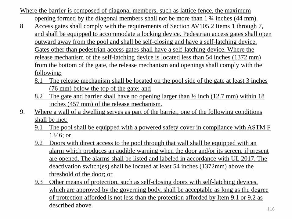
116
Where the barrier is composed of diagonal members, such as lattice fence, the maximum
opening formed by the diagonal members shall not be more than 1 ¾ inches (44 mm).
8 Access gates shall comply with the requirements of Section AV105.2 Items 1 through 7,
and shall be equipped to accommodate a locking device. Pedestrian access gates shall open
outward away from the pool and shall be self-closing and have a self-latching device.
Gates other than pedestrian access gates shall have a self-latching device. Where the
release mechanism of the self-latching device is located less than 54 inches (1372 mm)
from the bottom of the gate, the release mechanism and openings shall comply with the
following:
8.1 The release mechanism shall be located on the pool side of the gate at least 3 inches
(76 mm) below the top of the gate; and
8.2 The gate and barrier shall have no opening larger than ½ inch (12.7 mm) within 18
inches (457 mm) of the release mechanism.
9. Where a wall of a dwelling serves as part of the barrier, one of the following conditions
shall be met:
9.1 The pool shall be equipped with a powered safety cover in compliance with ASTM F
1346; or
9.2 Doors with direct access to the pool through that wall shall be equipped with an
alarm which produces an audible warning when the door and/or its screen, if present
are opened. The alarms shall be listed and labeled in accordance with UL 2017. The
deactivation switch(es) shall be located at least 54 inches (1372mm) above the
threshold of the door; or
9.3 Other means of protection, such as self-closing doors with self-latching devices,
which are approved by the governing body, shall be acceptable as long as the degree
of protection afforded is not less than the protection afforded by Item 9.1 or 9.2 as
described above.
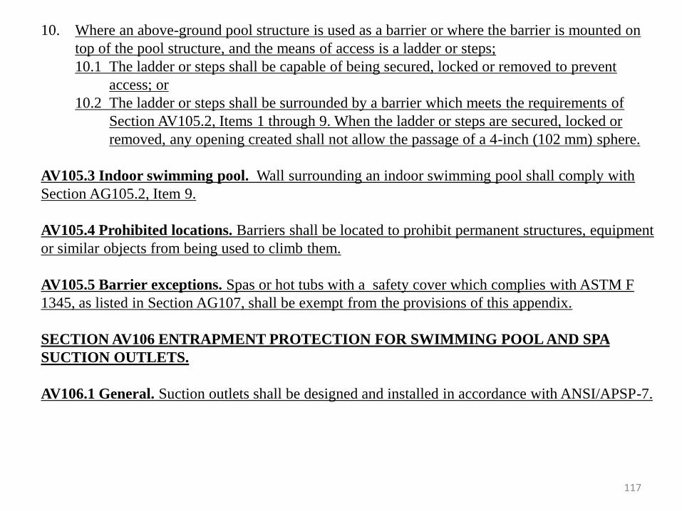
117
10. Where an above-ground pool structure is used as a barrier or where the barrier is mounted on
top of the pool structure, and the means of access is a ladder or steps;
10.1 The ladder or steps shall be capable of being secured, locked or removed to prevent
access; or
10.2 The ladder or steps shall be surrounded by a barrier which meets the requirements of
Section AV105.2, Items 1 through 9. When the ladder or steps are secured, locked or
removed, any opening created shall not allow the passage of a 4-inch (102 mm) sphere.
AV105.3 Indoor swimming pool. Wall surrounding an indoor swimming pool shall comply with
Section AG105.2, Item 9.
AV105.4 Prohibited locations. Barriers shall be located to prohibit permanent structures, equipment
or similar objects from being used to climb them.
AV105.5 Barrier exceptions. Spas or hot tubs with a safety cover which complies with ASTM F
1345, as listed in Section AG107, shall be exempt from the provisions of this appendix.
SECTION AV106 ENTRAPMENT PROTECTION FOR SWIMMING POOL AND SPA
SUCTION OUTLETS.
AV106.1 General. Suction outlets shall be designed and installed in accordance with ANSI/APSP-7.
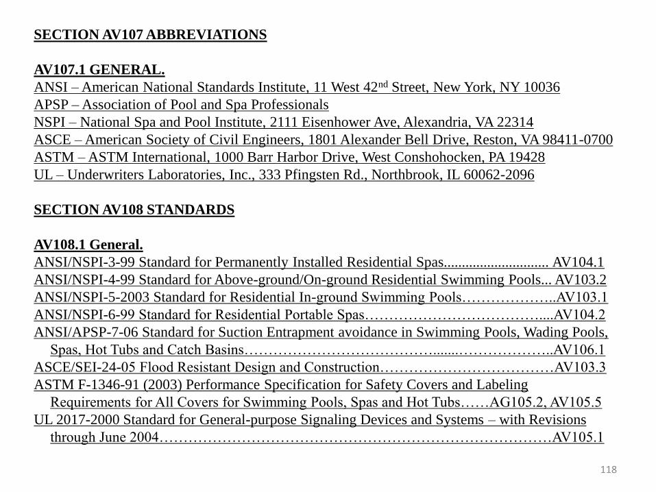
118
SECTION AV107 ABBREVIATIONS
AV107.1 GENERAL.
ANSI – American National Standards Institute, 11 West 42nd Street, New York, NY 10036
APSP – Association of Pool and Spa Professionals
NSPI – National Spa and Pool Institute, 2111 Eisenhower Ave, Alexandria, VA 22314
ASCE – American Society of Civil Engineers, 1801 Alexander Bell Drive, Reston, VA 98411-0700
ASTM – ASTM International, 1000 Barr Harbor Drive, West Conshohocken, PA 19428
UL – Underwriters Laboratories, Inc., 333 Pfingsten Rd., Northbrook, IL 60062-2096
SECTION AV108 STANDARDS
AV108.1 General.
ANSI/NSPI-3-99 Standard for Permanently Installed Residential Spas............................. AV104.1
ANSI/NSPI-4-99 Standard for Above-ground/On-ground Residential Swimming Pools... AV103.2
ANSI/NSPI-5-2003 Standard for Residential In-ground Swimming Pools………………..AV103.1
ANSI/NSPI-6-99 Standard for Residential Portable Spas………………………………....AV104.2
ANSI/APSP-7-06 Standard for Suction Entrapment avoidance in Swimming Pools, Wading Pools,
Spas, Hot Tubs and Catch Basins………………………………….......………………..AV106.1
ASCE/SEI-24-05 Flood Resistant Design and Construction………………………………AV103.3
ASTM F-1346-91 (2003) Performance Specification for Safety Covers and Labeling
Requirements for All Covers for Swimming Pools, Spas and Hot Tubs……AG105.2, AV105.5
UL 2017-2000 Standard for General-purpose Signaling Devices and Systems – with Revisions
through June 2004………………………………………………………………………AV105.1
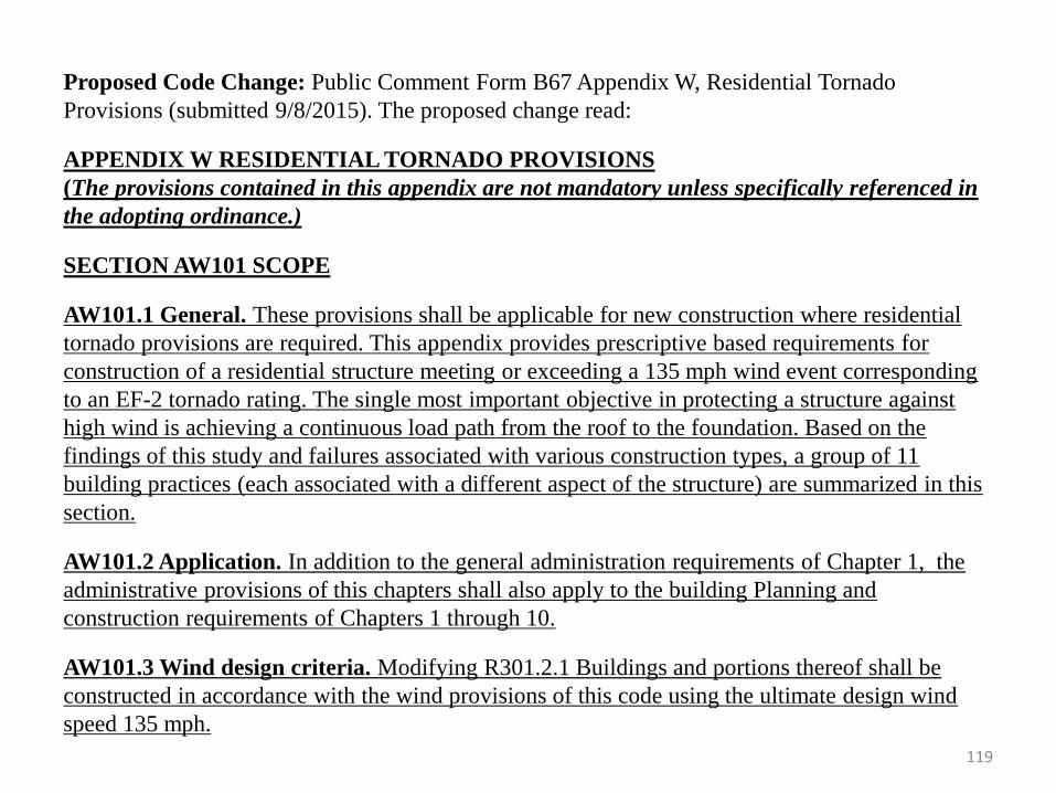
119
Proposed Code Change: Public Comment Form B67 Appendix W, Residential Tornado
Provisions (submitted 9/8/2015). The proposed change read:
APPENDIX W RESIDENTIAL TORNADO PROVISIONS
(The provisions contained in this appendix are not mandatory unless specifically referenced in
the adopting ordinance.)
SECTION AW101 SCOPE
AW101.1 General. These provisions shall be applicable for new construction where residential
tornado provisions are required. This appendix provides prescriptive based requirements for
construction of a residential structure meeting or exceeding a 135 mph wind event corresponding
to an EF-2 tornado rating. The single most important objective in protecting a structure against
high wind is achieving a continuous load path from the roof to the foundation. Based on the
findings of this study and failures associated with various construction types, a group of 11
building practices (each associated with a different aspect of the structure) are summarized in this
section.
AW101.2 Application. In addition to the general administration requirements of Chapter 1, the
administrative provisions of this chapters shall also apply to the building Planning and
construction requirements of Chapters 1 through 10.
AW101.3 Wind design criteria. Modifying R301.2.1 Buildings and portions thereof shall be
constructed in accordance with the wind provisions of this code using the ultimate design wind
speed 135 mph.
120
AW101.4 Lumber sheathing. Only OSB or plywood sheathing is permitted. Dimensional lumber
sheathing may not be used. Allowable spans and attachment for lumber used as roof or exterior
wall sheathing shall conform to the following:
AW101.4.1 16” Framing. For rafter, stud, or beam spacing of 16 inches the minimum nominal
sheathing panel thickness will be 7/16”, the minimum wood structural panel span rating 24/16,
to be nailed with 8d ring shank (0.131” x 2.5”) or 10d (0.148” x 3”) nails on 4” on center along
the edges and 6” on center in the field.
AW101.4.2 24” Framing. For rafter, stud or beam spacing of 24 inches the minimum nominal
sheathing panel thickness will be 23/32”, the minimum wood structural panel span rating 24/16
to be nailed with 8d ring shank (0.131” x 2.5”) or 10d (0.148” x 3”) nails on 4” on center along
the edges and 4” on center in the field.
AW101.5 Ceiling joist and rafter connections. In addition to the provisions of Chapter 8, ceiling
joists and rafters shall be nailed to each other in a manner to achieve a connection that can transfer
a 500 lb. force in both compression and tension across the connection.
AW101.6 Rafter uplift resistance. Individual rafters shall be attached to supporting wall
assemblies by connections capable of resisting uplift forces of 500 lb..
AW101.7 Gable end walls. Gable end walls will be sheathed per AW101.4 and will have
connections to both a.)supporting wall assemblies and b.) roof framing by connections capable of
resisting uplift forces of 500 lb. in both compression and tension across the connection.
AW101.8 Exterior wall bracing. Only continuous sheathing methods per R602.10.4.2 may be
121
used to brace exterior walls. Frame garage doors using the sheathed portal frame method CS-PF.
Lumber sheathing and attachment per AF101.4. Any form of intermittent bracing is not allowed
on an exterior wall. Intermittent bracing may only be used for interior braced wall lines.
AW101.9 Multi story construction. Nail upper and lower story wall sheathing to common rim
board in order to maintain continuity between stories.
AW101.10 Wood floor above crawl space construction. Extend structural wood sheathing to lap
the sill plate. Nail to sill plate using a 4” on center along the edges. Nail to rim board if present
with 8d ring shank (0.131” x 2.5”) or 10d (0.148” x 3”) nails on 4” on center along both the top
and bottom edges of the rim board.
AW101.11 Garage doors. Garage doors are to be wind rated to 135 mph.
Summary of Change: The submitter noted the proposal was to allow communities in Oklahoma
the option of adopting a wind code that addressed Tornados through EF2 (up to 135 mph), which
accounts for 90 to 95 percent of tornados and up to 80 to 85 percent of the damage due to an EF5
tornado. (Reference: May 20, 2013 NSF report by Graettinger and Ramseyer et.al.)
Committee Commentary: The committee reviewed the comment form and felt it was a good
proposal.
Committee Action Taken: Unanimous vote to “Approve Public Comment Form B67 as Written”
(9/9/2015)

122
Commission Action Taken: The Commission voted at the October 20, 2015 meeting
to approve the presentation as presented except for the specific modifications made by
the Commission.