OIML R 49-2 (E) Edition 2006 · instruments, test laboratories, etc. may simultaneously apply OIML...
77
Water meters intended for the metering of cold potable water and hot water Part 2: Test methods Compteurs d’eau destinés au mesurage de l’eau potable froide et de l’eau chaude Partie 2: Méthodes d’essais OIML R 49-2 Edition 2006 (E) OIML R 49-2 Edition 2006 (E) ORGANISATION INTERNATIONALE DE MÉTROLOGIE LÉGALE INTERNATIONAL ORGANIZATION OF LEGAL METROLOGY INTERNATIONAL RECOMMENDATION
Transcript of OIML R 49-2 (E) Edition 2006 · instruments, test laboratories, etc. may simultaneously apply OIML...

Water meters intended for the metering of cold potable water and hot water
Part 2: Test methods
Compteurs d’eau destinés au mesurage de l’eau potable froideet de l’eau chaude
Partie 2: Méthodes d’essais
OIM
LR49
-2 E
ditio
n 20
06 (E
)
OIML R 49-2Edition 2006 (E)
ORGANISATION INTERNATIONALE
DE MÉTROLOGIE LÉGALE
INTERNATIONAL ORGANIZATION
OF LEGAL METROLOGY
INTERNATIONAL
RECOMMENDATION
OIML R 49-2: 2006 (E)
2
Contents
Foreword .....................................................................................................................................4 PART 2: TEST METHODS.................................................................................................................................... 5 1 SCOPE ............................................................................................................................................................. 5 2 TERMINOLOGY ........................................................................................................................................... 5 3 REFERENCE CONDITIONS........................................................................................................................ 6 4 SYMBOLS, UNITS AND EQUATIONS....................................................................................................... 7 5 EXTERNAL EXAMINATION...................................................................................................................... 7
5.1 Object of the examination ................................................................................................................. 7 5.2 Preparation ........................................................................................................................................ 7 5.3 Examination procedures.................................................................................................................... 7
6 PERFORMANCE TESTS FOR ALL WATER METERS........................................................................ 12 6.1 Requirements common to all tests .................................................................................................. 12 6.2 Static pressure test (R 49-1, 6.2.5) .................................................................................................. 13 6.3 Determination of intrinsic errors (of indication) (R 49-1, 6.2.4)
and the effects of meter orientation (R 49-1, 6.2.4.3) ..................................................................... 14 6.4 Water temperature test (R 49-1, 3.2.7)............................................................................................ 20 6.5 Water pressure test (R 49-1, 3.2.7) ................................................................................................. 20 6.6 Flow reversal test (R 49-1, 3.2.6).................................................................................................... 21 6.7 Pressure loss test (R 49-1, 6.2.6)..................................................................................................... 22 6.8 Flow disturbance tests (R 49-1, 5.3.4) ............................................................................................ 25 6.9 Endurance tests (R 49-1, 6.2.7)....................................................................................................... 26 6.10 Magnetic field testing ..................................................................................................................... 32 6.11 Environmental testing ..................................................................................................................... 32
7 PERFORMANCE TESTS RELATED TO INFLUENCE QUANTITIES AND DISTURBANCES...... 32 7.1 General requirements (R 49-1, A.1)................................................................................................ 32 7.2 Dry heat (non-condensing) (R 49-1, A.6.1) .................................................................................... 35 7.3 Cold (R 49-1, A.6.2) ....................................................................................................................... 36 7.4 Damp heat, cyclic (condensing) (R 49-1, A.6.3) ............................................................................ 37 7.5 Power voltage variation (R 49-1, A.6.4) ......................................................................................... 38 7.6 Vibration (random) (R 49-1, A.6.5) ................................................................................................ 39 7.7 Mechanical shock (R 49-1, A.6.6) .................................................................................................. 40 7.8 Short time power reduction (R 49-1, A.6.7) ................................................................................... 41 7.9 Bursts (R 49-1, A.6.8)..................................................................................................................... 42 7.10 Electrostatic discharge (R 49-1, A.6.9) ........................................................................................... 44 7.11 Electromagnetic susceptibility (R 49-1, A.6.10)............................................................................. 45 7.12 Static magnetic field (R 49-1, 6.2.8) .............................................................................................. 47
8 TEST PROGRAM FOR TYPE APPROVAL............................................................................................. 48 8.1 Number of samples required ........................................................................................................... 48 8.2 Performance test applicable to all water meters.............................................................................. 48 8.3 Performance tests applicable to electronic water meters, mechanical water
meters fitted with electronic devices, and their separable parts ...................................................... 49 8.4 Type approval of separable parts of a water meter ......................................................................... 50 8.5 Families of water meters ................................................................................................................. 51
9 TESTS FOR INITIAL VERIFICATION.................................................................................................... 51 9.1 Initial verification of complete and combined water meters ........................................................... 51 9.2 Initial verification of separable parts of a water meter.................................................................... 52
10 PRESENTATION OF RESULTS................................................................................................................ 52 10.1 Object of the reports........................................................................................................................ 52 10.2 Identification and test data to be included in records...................................................................... 52

OIML R 49-2: 2006 (E)
3
ANNEX A (Mandatory) ........................................................................................................................................ 54 Type examination and testing of checking facilities of electronic devices ANNEX B (Mandatory)......................................................................................................................................... 59 Calculating the relative error (of indication) of a water meter ANNEX C (Mandatory) ........................................................................................................................................ 63 Installation requirements for flow disturbance tests ANNEX D (Mandatory) ........................................................................................................................................ 64 Type evaluation of a family of water meters ANNEX E (Informative)........................................................................................................................................ 66 Examples of methods and components used for testing concentric water meters ANNEX F (Informative)........................................................................................................................................ 69 Determining the density of water ANNEX G (Informative) ....................................................................................................................................... 71 Maximum uncertainties in the measurement of influence factors and disturbances ANNEX H (Informative) ....................................................................................................................................... 73 Pressure loss test Pressure tappings, hole and slot details Bibliography........................................................................................................................................................... 76

OIML R 49-2: 2006 (E)
4
Foreword
The International Organization of Legal Metrology (OIML) is a worldwide, intergovernmental organization whose primary aim is to harmonize the regulations and metrological controls applied by the national metrological services, or related organizations, of its Member States. The main categories of OIML publications are:
International Recommendations (OIML R), which are model regulations that establish the metrological characteristics required of certain measuring instruments and which specify methods and equipment for checking their conformity. OIML Member States shall implement these Recommendations to the greatest possible extent;
International Documents (OIML D), which are informative in nature and which are intended to harmonize and improve work in the field of legal metrology;
International Guides (OIML G), which are also informative in nature and which are intended to give guidelines for the application of certain requirements to legal metrology; and
International Basic Publications (OIML B), which define the operating rules of the various OIML structures and systems.
OIML Draft Recommendations, Documents and Guides are developed by Technical Committees or Subcommittees which comprise representatives from the Member States. Certain international and regional institutions also participate on a consultation basis. Cooperative agreements have been established between the OIML and certain institutions, such as ISO and the IEC, with the objective of avoiding contradictory requirements. Consequently, manufacturers and users of measuring instruments, test laboratories, etc. may simultaneously apply OIML publications and those of other institutions.
International Recommendations, Documents, Guides and Basic Publications are published in English (E) and translated into French (F) and are subject to periodic revision.
Additionally, the OIML publishes or participates in the publication of Vocabularies (OIML V) and periodically commissions legal metrology experts to write Expert Reports (OIML E). Expert Reports are intended to provide information and advice, and are written solely from the viewpoint of their author, without the involvement of a Technical Committee or Subcommittee, nor that of the CIML. Thus, they do not necessarily represent the views of the OIML.
This publication - reference OIML R 49-2, Edition 2006 - was developed by the Subcommittee TC 8/SC 5 Water meters. This version supersedes OIML R 49-2 Water meters intended for the metering of cold potable water. Part 2: Test methods (Edition 2004) and OIML R 72 Hot water meters (Edition 1985) It was approved for final publication by the International Committee of Legal Metrology in 2006 and will be submitted to the International Conference of Legal Metrology in 2008 for formal sanction.
OIML Publications may be downloaded from the OIML web site in the form of PDF files. Additional information on OIML Publications may be obtained from the Organization’s headquarters:
Bureau International de Métrologie Légale 11, rue Turgot - 75009 Paris - France Telephone: 33 (0)1 48 78 12 82 Fax: 33 (0)1 42 82 17 27 E-mail: [email protected] Internet: www.oiml.org

OIML R 49-2: 2006 (E)
5
Water meters intended for the metering of cold potable water and hot water
Part 2: Test methods
1 SCOPE This Recommendation is applicable to the type evaluation and initial verification testing of water meters intended for the metering of cold potable water and hot water as defined in OIML R 49-1 [1]. OIML Certificates of Conformity may be issued for water meters under the scope of the OIML Certificate System, providing that the three parts of this Recommendation are used in accordance with the rules of the System.
This Recommendation sets out details of the test program, principles, equipment and procedures to be used for the type evaluation and initial verification testing of a meter type.
The provisions of this Recommendation also apply to ancillary devices, if required by national regulations.
The provisions include requirements for testing the complete water meter and for testing the measurement transducer (including the flow or volume sensor) and the calculator (including the indicating device) of a water meter as separate units.
2 TERMINOLOGY The terms and definitions given in R 49-1 [1] apply in this Recommendation.
Some of the definitions used in this Recommendation conform to terminology used in IEC 60068-1 [10] and are adapted where necessary.
2.1 Test flowrate
Mean flowrate during a test, calculated from the indications of a calibrated reference device. The quotient of the actual volume passing through the water meter divided by the time for that volume to pass through the water meter.
2.2 In-line meter
Type of water meter fitted into a closed conduit by means of the meter end connections (either threaded or flanged) provided.
2.3 Concentric meter
Type of water meter fitted into a closed conduit by means of an intermediate fitting called a manifold. The inlet and outlet passages of the meter and the manifold, at the interface between them, are coaxial.
2.4 Concentric meter manifold
Pipe fitting specific to the connection of a concentric meter.
2.5 Complete meter
Meter that does not have separable measurement transducer (including flow or volume sensor) and calculator (including indicating device).

OIML R 49-2: 2006 (E)
6
2.6 Combined meter
Meter which has separable measurement transducer (including flow or volume sensor) and calculator (including indicating device).
2.7 Combination meter
Meter comprising one large meter, one small meter and a changeover device that, depending on the magnitude of the flowrate passing through the meter, automatically directs the flow through either the small or large meter or both.
2.8 Equipment under test
Complete water meter, a part of a water meter or an ancillary device.
2.9 Flow sensor or volume sensor
Part of the water meter (such as a disc, piston, wheel, turbine element, or electromagnetic coil) that senses the flow rate or volume of water passing through the meter.
Note: The measurement transducer includes the flow sensor or volume sensor.
2.10 Temperature stability
Temperature stability has been reached when all parts of the equipment under test are within 3 °C of each other, or as otherwise specified in the relevant specification of its final temperature.
2.11 Pre-conditioning
Treatment of the equipment under test, with the object of eliminating or partially counteracting the effects of its previous history. Where called for, this is the first process in the test procedure.
2.12 Conditioning
Exposure of the equipment under test to an environmental condition (influence factor or disturbance) in order to determine the effect of such a condition on it.
2.13 Recovery
Treatment of the equipment under test, after conditioning, in order that the properties of the equipment under test may be stabilized before measurement.
3 REFERENCE CONDITIONS All applicable influence quantities, except for the influence quantity being tested, shall be held at the following values during type approval tests on a water meter. However, for influence factors and disturbances for electronic water meters, it is permissible to use the reference conditions defined in the applicable IEC standard:
Flowrate (reference flowrate): 0.7 × (Q2 + Q3) ± 0.03 × (Q2 + Q3)
Water temperature: Within ± 5 °C of reference value(s) (See Table 1 of R 49-1 [1])
Water pressure Within rated operating conditions (See 5.4 of R 49-1 [1])
Ambient temperature range: 15 °C to 25 °C
Ambient relative humidity range: 45 % to 75 %
Ambient atmospheric pressure range: 86 kPa to 106 kPa [0.86 bar to 1.06 bar]
Power supply voltage (mains AC): Nominal voltage (Unom) ± 5%
Power supply frequency: Nominal frequency (fnom) ± 2%
Power supply voltage (battery): A voltage V in the range Ubmin ≤ V ≤ Ubmax

OIML R 49-2: 2006 (E)
7
During each test, the temperature and relative humidity shall not vary by more than 5 °C or 10 % respectively within the reference range.
4 SYMBOLS, UNITS AND EQUATIONS Equations, symbols and their units, concerning the calculation of the error (of indication) of a water meter used in this Recommendation, are given in Annex B.
5 EXTERNAL EXAMINATION During the external examination, all relevant values, dimensions and observations shall be recorded.
Notes: 1) For presentation of the results of type examinations see clause 10. 2) The relevant sections of R 49-1 are shown in parentheses below.
5.1 Object of the examination
To verify that the water meter meets the requirements of R 49-1 with respect to the design of the indicating device, the marking of the meter and the application of protection devices.
5.2 Preparation
Linear measurements that have to be taken from the meter shall be made using traceable, calibrated measuring devices.
The actual or apparent dimensions of the scales of the indicating device shall be taken without removing the meter lens or disassembling the meter.
Note: A traveling microscope (cathetometer) may be used to measure the width, spacing and height of the scale divisions and the height of the numerals.
5.3 Examination procedures
The following aspects of the meter design shall be examined on at least one meter from the sample.
Either the same meter sample may be used for all the external examinations or different meters from the samples submitted may be used for some of the examinations.
5.3.1 Marks and inscriptions (R 49-1, 5.6)
1) Verify that the water meter is clearly and indelibly marked with the following information, either grouped or distributed on the casing, the indicating device dial, an identification plate or on the meter cover if it is not detachable:
a) Unit of measurement: cubic metre or m3; b) The accuracy class, where it differs from accuracy class 2; c) The numerical value of Q3, the ratio Q3/Q1 and the ratio Q2/Q1 where it differs
from 1.6; d) The type approval sign according to national regulations; e) The name or trade mark of the manufacturer; f) The year of manufacture and serial number (as near as possible to the indicating
device); g) The direction of flow (shown on both sides of the body; or on one side only,
provided that the direction of flow arrow will be easily visible under all circumstances);
h) The maximum admissible pressure (MAP), if it exceeds 1 MPa (10 bar); Note: The unit bar may be used where national regulations permit.
i) The letter V or H, if the meter can only be operated in the vertical or horizontal position;
OIML R 49-2: 2006 (E)
8
j) The temperature class, where it differs from T30; k) The maximum pressure loss, if required;
and, for water meters with electronic devices, the following additional inscriptions where appropriate:
l) For an external power supply: the voltage and frequency; m) For a replaceable battery: the latest date by which the battery has to be replaced; n) For a non-replaceable battery: the latest date by which the water meter has to be
replaced. 2) Complete the section reference R 49-1, 5.6 (a) – (n) in 4.1.1 of report R 49-3.
5.3.2 Indicating device (R 49-1, 5.7)
5.3.2.1 Function (R 49-1, 5.7.1.1)
1) Verify that the indicating device provides an easily read, reliable and unambiguous visual indication of the indicated volume.
2) Verify that the indicating device includes visual means for testing and calibration.
3) If the indicating device includes additional elements for testing and calibration by other methods, e.g. for automatic testing and calibration, record the type(s) of device.
4) If the meter is a combination meter with two indicating devices, clauses 5.3.2.1 to 5.3.2.6 apply to both indicating devices.
5) Complete the section reference R 49-1, 5.7.1.1 in 4.1.1 of report R 49-3.
5.3.2.2 Unit of measurement, symbol and its placement (R 49-1, 5.7.1.2)
1) Verify that the indicated volume of water is expressed in cubic metres.
2) Verify that the symbol m3 appears on the dial or immediately adjacent to the numbered display.
3) Complete the section reference R 49-1, 5.7.1.2 in 4.1.1 of report R 49-3.
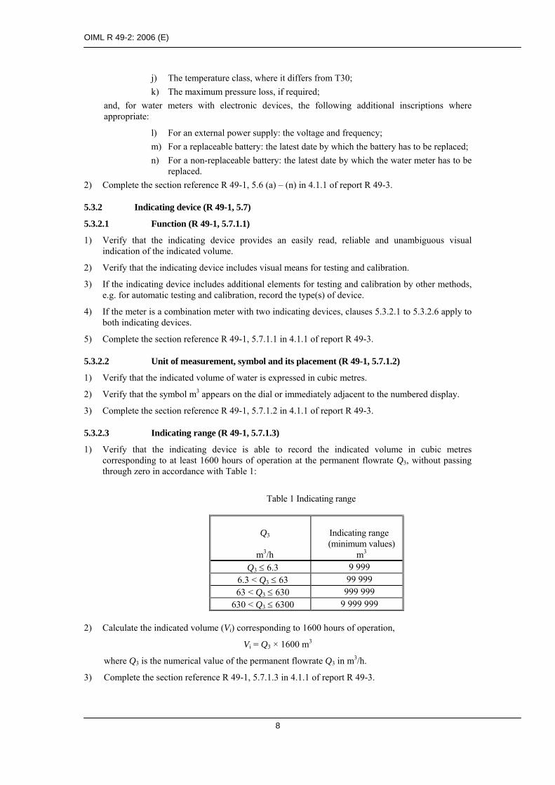
5.3.2.3 Indicating range (R 49-1, 5.7.1.3)
1) Verify that the indicating device is able to record the indicated volume in cubic metres corresponding to at least 1600 hours of operation at the permanent flowrate Q3, without passing through zero in accordance with Table 1:
Table 1 Indicating range
Q3
m3/h
Indicating range (minimum values)
m3 Q3 ≤ 6.3 9 999
6.3 < Q3 ≤ 63 99 999 63 < Q3 ≤ 630 999 999
630 < Q3 ≤ 6300 9 999 999 2) Calculate the indicated volume (Vi) corresponding to 1600 hours of operation,
Vi = Q3 × 1600 m3
where Q3 is the numerical value of the permanent flowrate Q3 in m3/h.
3) Complete the section reference R 49-1, 5.7.1.3 in 4.1.1 of report R 49-3.

OIML R 49-2: 2006 (E)
9
5.3.2.4 Color coding for indicating devices (R 49-1, 5.7.1.4)
1) Verify that either:
• The color black is used to indicate the cubic metre and its multiples;
• The color red is used to indicate sub-multiples of a cubic metre;
• The colors are applied either to the pointers, indexes, numbers, wheels discs, dials or aperture frames;
or,
• Other means of indicating the cubic metre are used in which there is no ambiguity in distinguishing between the primary indication and alternative displays, e.g. sub-multiples for verification and testing.
2) Complete the section reference R 49-1, 5.7.1.4 in 4.1.1 of report R 49-3.
5.3.2.5 Types of indicating device (R 49-1, 5.7.2)
5.3.2.5.1 Type 1 - Analogue device (R 49-1, 5.7.2.1)
1) If a type 1 indicating device has been used, verify that volume is indicated by:
• Either continuous movement of one or more pointers moving relative to graduated scales; • or continuous movement of one or more circular scales or drums, each passing an index.
2) Verify that the value expressed in cubic metres for each scale division is of the form 10n, where n is a positive or a negative whole number or zero, thereby establishing a system of consecutive decades.
3) Verify that each scale is either graduated in values expressed in cubic metres or accompanied by a multiplying factor (× 0.001; × 0.01; × 1; × 10; × 100; × 1000, etc.).
4) Verify that the rotational movements of the pointers or circular scales are clockwise.
5) Verify that the linear movement of the pointers or scales is from left to right.
6) Verify that the movement of the numbered roller indicators is upwards.
7) Complete the section reference R 49-1, 5.7.2.1 in 4.1.1 of report R 49-3.
5.3.2.5.2 Type 2 – Digital device (R 49-1, 5.7.2.2)
1) Verify that the indicated volume is given by a line of digits, appearing in one or more apertures.
2) Verify that the advance of one digit is completed while the digit of the next immediately lower decade changes from 9 to 0.
3) Verify that the movement of the numbered roller indicators (drums) is upwards.
4) If the lowest value decade has a continuous movement, verify that the aperture is large enough to permit a digit to be read without ambiguity.
5) Verify that the actual or apparent height of the digits is at least 4 mm.
6) Complete the section reference R 49-1, 5.7.2.2 in 4.1.1 of report R 49-3.
5.3.2.5.3 Type 3 – Combination of analogue and digital devices (R 49-1, 5.7.2.3)
1) If the indicating device is a combination of type 1 and 2 devices, verify that the respective requirements of each apply (see 5.3.2.5.1 and 5.3.2.5.2).
2) Complete the section reference R 49-1, 5.7.2.3 in 4.1.1 of report R 49-3.

OIML R 49-2: 2006 (E)
10
5.3.2.6 Verification devices – First element of an indicating device – Verification interval (R 49-1, 5.7.4)
5.3.2.6.1 General requirements (R 49-1, 5.7.4.1)
1) Verify that the indicating device has the means for visual, non-ambiguous verification testing and calibration.
2) Note whether the visual verification display has a continuous or a discontinuous movement.
3) Note whether, in addition to the visual verification display, the indicating device includes provisions for rapid testing by the inclusion of complementary elements; (e.g. star wheels or discs), providing signals through externally attached sensors. Note the relationship, stated by the manufacturer, between the visual indication of volume and the signals emitted by these complementary devices.
4) Complete the section reference R 49-1, 5.7.4.1 in 4.1.1 of report R 49-3.
5.3.2.6.2 Visual verification display (R 49-1, 5.7.4.2)
5.3.2.6.2.1 Value of the verification scale interval (R 49-1, 5.7.4.2.1)
1) Verify that the value of the verification scale interval, expressed in cubic metres, is of the form 1 × 10n, or 2 × 10n, or 5 × 10n, where n is a positive or negative whole number, or zero.
2) For analogue and digital indicating devices with continuous movement of the first element, verify that the verification scale interval is formed from the division into 2, 5 or 10 equal parts of the interval between two consecutive digits of the first element.
3) For analogue and digital indicating devices with continuous movement of the first element, verify that numbering is not applied to the divisions between consecutive digits of the first element.
4) For digital indicating devices with discontinuous movement of the first element, the verification scale interval is the interval between two consecutive digits or incremental movements of the first element.
5) Complete the section reference R 49-1, 5.7.4.2.1 in 4.1.1 of report R 49-3.
5.3.2.6.2.2 Form of the verification scale (R 49-1, 5.7.4.2.2)
1) If the indicating device has continuous movement of the first element, check that the apparent scale spacing is not less than 1 mm and not more than 5 mm.
2) Verify that the scale consists of:
• Either lines of equal thickness not exceeding one-quarter of the scale spacing and differing only in length;
• or contrasting bands of a constant width equal to the scale spacing.
3) Verify that the apparent width of the pointer at its tip does not exceed one-quarter of the scale spacing.
4) Verify that the apparent width of the pointer at its tip does not exceed 0.5 mm.
5) Complete the section reference R 49-1, 5.7.4.2.2 in 4.1.1 of report R 49-3.
5.3.2.6.2.3 Resolution of the indicating device (R 49-1, 5.7.4.2.3)
1) Note the value of the verification scale interval, δV m3
2) Calculate the actual volume Va passed during 1 hour 30 minutes at the minimum flowrate Q1,
Va = Q1 × 1.5 m3
3) Calculate the resolution error of the indicating device εr,
a) For continuous movement of the first element:
OIML R 49-2: 2006 (E)
11
εr = 100 × (½ δV + ½ δV)/ Va %
= 100 × δV/ Va %.
b) For discontinuous movement of the first element: εr = 100 × (δV + δV)/ Va %
= 100 × 2δV/ Va %.
4) Verify that for accuracy class 1 meters, the value of the verification scale interval is small enough to ensure that the resolution error εr of the indicating device does not exceed 0.25 % of the actual volume required during 1 hour 30 minutes at the minimum flow rate, Q1.
εr ≤ 0.25 %
5) Verify that for accuracy class 2 meters, the verification scale interval is small enough to ensure that the resolution error εr of the indicating device does not exceed 0.5 % of the actual volume required during 1 hour 30 minutes at the minimum flow rate, Q1.
εr ≤ 0.5 %
6) Complete the section reference R 49-1, 5.7.4.2.3 in 4.1.1 of report R 49-3.
Notes: 1) When the display of the first element is continuous, an allowance shall be made for a
maximum error in each reading of not more than half of the verification scale interval.
2) When the display of the first element is discontinuous, an allowance shall be made for a maximum error in each reading of not more than one digit of the verification scale.
5.3.3 Verification marks and protection devices (R 49-1, 5.8)
1) Verify that a place has been provided on the meter for affixing the main verification mark, which is visible without dismantling the meter (R 49-1, 5.8.1).
2) Verify that the water meter includes protection devices which can be sealed to prevent, both before and after correct installation, dismantling or modification of the meter, its adjustment or correction device, without damaging these devices (R 49-1, 5.8.2). Note that, in the case of a combination meter, this requirement applies to both meters.
3) When access to parameters that influence the determination of the results of measurements is not protected by mechanical sealing devices, verify that the protection fulfils the following provisions (R 49-1, 5.8.3.1 a and b):
a) access is only allowed to authorized individual(s); b) where an access code is used, it is capable of being changed; c) the last intervention is stored in memory; d) the record stored in memory also includes the date and the identity of the
authorized individual(s); e) the last record stored in memory is accessible for at least 2 years; f) if it is possible to memorize more than one intervention, and if deletion of a
previous intervention must occur to permit a new record, the oldest record is deleted.
4) Where meters have parts that can be disconnected from one another by the user and which are inter-changeable, verify that:
a) it is not possible to access parameters that participate in the determination of results of measurements through disconnected points unless the provisions tested in 5.3.3, 3) above are fulfilled (R 49-1, 5.8.3.2 (a)); and that,

OIML R 49-2: 2006 (E)
12
b) interposing any device which may influence the accuracy is prevented by means of electronic and data processing securities or, if this is not possible, by mechanical means (R 49-1, 5.8.3.2 (b)).
5) Where meters have parts that can be disconnected from one another by the user and which are not inter-changeable, verify that:
a) it is not possible to access parameters that participate in the determination of results of measurements through disconnected points unless the provisions tested in 5.3.3, 3) above are fulfilled (R 49-1, 5.8.3.3);
b) interposing any device which may influence the accuracy is prevented by means of electronic and data processing securities or, if this is not possible, by mechanical means (R 49-1, 5.8.3.3);
c) they are provided with devices that prevent them from operating if the various parts are not connected according to the manufacturer’s configuration (R 49-1, 5.8.3.3);
d) they are provided with a device that prevents any measurement after any unauthorized disconnection and subsequent reconnection by the user (R 49-1, 5.8.3.3).
6) Complete the section reference R 49-1, 5.8.1 – 5.8.2 in 4.1.1 and 5.8.3.1 – 5.8.3.3 in 4.1.2 of report R 49-3.
6 PERFORMANCE TESTS FOR ALL WATER METERS During the performance tests, all relevant values, dimensions and observations shall be recorded.
Notes: 1) For presentation of the results of type evaluation tests see clause 10.
2) The relevant sub-clauses of R 49-1 are shown in parentheses below.
6.1 Requirements common to all tests
6.1.1 Water quality
Water meter tests shall be carried out using water. The water shall be that of the public potable water supply or shall meet the same requirements.
The water shall not contain any substance which might damage the meter or adversely affect its operation. It shall not contain air bubbles.
Note: If water is being recycled, measures shall be taken to prevent residual water in the meter from becoming harmful to human beings.
6.1.2 General rules concerning test installation and location
6.1.2.1 Freedom from spurious influences
Test rigs shall be so designed, constructed and used, that the performance of the rig itself shall not contribute significantly to the test error. To this end, high standards of rig maintenance and adequate supports and fittings are necessary to prevent vibration of the meter, the test rig and its accessories.
The test rig environment shall be such that the reference conditions of the test are met (see clause 3).
It shall be possible to carry out test readings rapidly and easily.
As part of the validation process, periodic inter-comparisons between test rigs shall be carried out in accordance with OIML International Document D 7 [5].
6.1.2.2 Group testing of meters
Meters are tested either individually or in groups. In the latter case the individual characteristics of the meters shall be precisely determined. Interaction between meters, and test rigs, shall be eliminated.

OIML R 49-2: 2006 (E)
13
When meters are tested in series, the pressure at the exit of each meter shall be sufficient to prevent cavitation.
6.1.2.3 Location
The environment chosen for meter tests shall be in accordance with the principles elaborated in OIML publication G 13 Planning of metrology and testing laboratories [7] and shall be free from disturbing influences (for example, ambient temperature, vibration).
6.2 Static pressure test (R 49-1, 6.2.5)
6.2.1 Object of the test
To verify that the water meter can withstand the specified hydraulic test pressure for the specified time without leakage or damage.
6.2.2 Preparation
1) Install the meters in the test rig either singly or in groups. 2) Bleed the test rig pipework and the water meters of air. 3) Ensure that the test rig is free from leaks. 4) Ensure that the supply pressure is free from pressure pulsations.
6.2.3 Test procedure
6.2.3.1 In-line meters
1) Increase the hydraulic pressure to 1.6 times the maximum admissible pressure (MAP) of the meter and hold it for 15 minutes.
2) Examine the meters for physical damage, for external leaks and for leaks into the indicating device.
3) Increase the hydraulic pressure to twice the MAP and hold this pressure level for 1 minute. 4) Examine the meters for physical damage, for external leaks and for leaks into the indicating
device. 5) Complete test report 5.1 in R 49-3.
Additional requirements:
a) Increase and decrease the pressure gradually without pressure surges. b) Apply only the reference temperatures for this test.
6.2.3.2 Concentric meters
The test procedure in 6.2.3.1 also applies to pressure testing of concentric water meters; however the seals located at the concentric meter/manifold interface (see example in Annex E, Figure E.1) shall also be tested to ensure that undisclosed internal leaks between the inlet and outlet passages of the meter do not occur.
When the pressure test is carried out the meter and manifold shall be tested together.
Requirements for testing concentric meters may vary according to the design therefore an example of a test method is shown in the informative Annex E, Figures E.2 and E.3.
6.2.4 Acceptance criteria
There shall be no leakage from the meter or leakage into the indicating device, or physical damage, resulting from any of the pressure tests described in 6.2.3.1 and 6.2.3.2.

OIML R 49-2: 2006 (E)
14
6.3 Determination of intrinsic errors (of indication) (R 49-1, 6.2.4) and the effects of meter orientation (R 49-1, 6.2.4.3)
6.3.1 Object of the test
To determine the intrinsic errors (of indication) of the water meter and the effects of the meter orientation on the error (of indication).
6.3.2 Preparation
6.3.2.1 Description of the test rig
The method described here for determining the meter errors (of indication) is the so-called “collection” method, in which the quantity of water passed through the water meter is collected in one or more collecting vessels and the quantity determined volumetrically or by weighing. Other methods may be used, provided the requirements of 6.3.2.2.6.1 are met.
The checking of the errors (of indication) consists in comparing the volume indications given by the meter under reference conditions against a calibrated reference device.
For the purpose of these tests, a meter should be tested without its temporary supplementary devices attached (if any).
The test rig consists, typically, of:
a) a water supply (non-pressurized tank, pressurized tank, pump, etc.); b) pipework; c) a calibrated reference device (calibrated volumetric tank, weighing system,
reference meter, etc.); d) means for measuring the time of the test; e) devices for automating the tests (if required); f) means for measuring water temperature; g) means for measuring water pressure.
6.3.2.2 Pipework
6.3.2.2.1 Description
Pipework shall include:
a) a test section in which the meter(s) is (are) placed; b) means for establishing the desired flowrate; c) one or two isolating devices; d) means for determining the flowrate;
and if necessary:
e) means for checking that the pipework is filled to a datum level before and after each test;
f) one or more air bleeds; g) a non-return device; h) an air separator; i) a filter.
During the test, flow leakage, flow input and flow drainage shall not be permitted either between the meter(s) and the reference device or from the reference device.
The pipework shall be such that a positive pressure of at least 0.03 MPa (0.3 bar) exists immediately downstream of the meter at all flowrates (including zero flowrate).
6.3.2.2.2 Test section
The test section shall include, in addition to the meter(s):

OIML R 49-2: 2006 (E)
15
a) one or more pressure tappings for the measurement of pressure, of which one pressure tapping is situated upstream of, and close to, the (first) meter;
b) means for measuring the temperature of the water close to the entry to the (first) meter.
The presence of any pipe components or devices placed in or near the measuring section shall not cause cavitation or flow disturbances capable of altering the performance of the meters or causing errors (of indication).
6.3.2.2.3 Precautions to be taken during tests
1) Check that the operation of the test rig is such that, during a test, the actual volume of water that flows through the meter(s) is equal to that measured by the reference device.
2) Check that the pipe (for example, the swan-neck in the outlet pipe) is filled to the same datum level at the beginning and at the end of the test.
3) Bleed all air from the interconnecting pipework and the meter(s). The manufacturer may recommend a procedure that ensures that all air is bled from the meter.
4) Take all precautions necessary to avoid the effects of vibration and shock.
6.3.2.2.4 Special arrangements for the installation of meters
6.3.2.2.4.1 Avoidance of erroneous measurements
The following reminder of the most frequent causes of erroneous measurements and the necessary precautions for the installation of water meters on the test bench is prompted by the recommendations of OIML D 4 [3] which aims to help achieve a test installation in which:
a) the hydrodynamic flow characteristics cause no discernible difference to the meter functioning when compared with hydrodynamic flow characteristics which are undisturbed;
b) the overall error of the method employed does not exceed the stipulated value (see 6.3.2.2.6.1).
6.3.2.2.4.2 Need for straight lengths of pipe or a flow straightener
The accuracy of non-volumetric water meters can be affected by upstream disturbance caused, for example, by the presence of bends, tees, valves or pumps.
In order to counteract these effects:
The meter shall be installed in accordance with the manufacturer’s instructions;
The connecting pipework shall have an internal diameter matched to the relevant meter connection;
If necessary, a flow straightener shall be installed upstream of the straight pipe length.
6.3.2.2.4.3 Common causes of flow disturbance
A flow can be subject to two types of disturbance: velocity-profile distortion and swirl, both of which may affect the errors of indication of a water meter.
Velocity-profile distortion is typically caused by an obstruction partially blocking the pipe, for instance the presence of a partly closed valve or a misaligned flange joint. This can easily be eliminated by careful application of installation procedures.
Swirl can be caused either by two or more bends in different planes or a single bend in combination with a reducer or partially closed valve. This effect can be controlled either by ensuring an adequate length of straight pipe upstream of the water meter, or by installing a flow straightening device, or by a

OIML R 49-2: 2006 (E)
16
combination of the two. However, where possible, these types of pipework configurations should be avoided.
6.3.2.2.4.4 Volumetric water meters
Some types of water meter, e.g. volumetric water meters (that is, involving measuring chambers with mobile walls), such as oscillating piston or nutating disc meters, are considered insensitive to upstream installation conditions; hence no special conditions are required.
6.3.2.2.4.5 Meters employing electromagnetic induction
Meters employing electromagnetic induction as a measuring principle may be affected by the conductivity of the test water.
The conductivity of the water used for testing this type of meter should be within the operational range of conductivity specified by the meter manufacturer.
6.3.2.2.4.6 Other measuring principles
Other types of meter may require flow conditioning when measuring the errors of indication and in such cases the manufacturer’s recommended installation requirements shall be followed (see 6.8).
These installation requirements should be reported in the type approval certificate for the water meter.
Concentric meters that are proven to be unaffected by manifold configuration (see 6.3.2.2.4.4) may be tested and used with any suitable manifold arrangement.
6.3.2.2.5 Errors of test commencement and termination
Adequate precautions shall be taken to reduce the uncertainties resulting from operation of test rig components during the test.
Details of the precautions to be taken are given in 6.3.2.2.5.1 and 6.3.2.2.5.2 for two cases encountered in the “collection” method.
6.3.2.2.5.1 Tests with readings taken with the meter at rest
This method is generally known as the standing-start-and-finish method.
Flow is established by opening a valve, preferably situated downstream of the meter, and it is stopped by closure of this valve. The meter is read when the registration is stationary.
Time is measured between the beginning of the movement of the valve at opening and at the end of closure.
Whilst flow is beginning and during the period of running at the specified constant flowrate, the error (of indication) of the meter varies as a function of the changes in flowrate (the error curve).
Whilst the flow is being stopped, the combination of the inertia of the moving parts of the meter and the rotational movement of the water inside the meter may cause an appreciable error to be introduced in certain types of meter and for certain test flowrates.
It has not been possible, in this case, to determine a simple empirical rule which lays down conditions so that this error may always be negligible.
In case of doubt, it is advisable:
a) To increase the volume and duration of the test; b) To compare the results with those obtained by one or more other methods, and
in particular the method described in 6.3.2.2.5.2, which eliminates the causes of uncertainty given above.
For some types of electronic water meters with pulse outputs that are used for testing, the response of the meter to changes in flowrate may be such that valid pulses are emitted after closure of the valve. In this case means shall be provided to count these additional pulses.

OIML R 49-2: 2006 (E)
17
Where pulse outputs are used for testing meters, it shall be checked that the volume indicated by the pulse count corresponds to the volume displayed on the indicating device.
6.3.2.2.5.2 Tests with readings taken under stable flow conditions and diversion of flow
This method is generally known as the flying-start-and-finish method.
The measurement is carried out when flow conditions have stabilized.
A switch diverts the flow into a calibrated vessel at the beginning of the measurement and diverts it away at the end.
The meter is read whilst in motion.
The reading of the meter is synchronized with the movement of the flow switch.
The volume collected in the vessel is the actual volume passed.
The uncertainty introduced into the volume may be considered negligible if the times of motion of the flow switch in each direction are identical within 5 % and if this time is less than 1/50 of the total time of the test.
6.3.2.2.6 Calibrated reference device
6.3.2.2.6.1 Overall uncertainty of the value of measured actual volume
When a test is conducted, the expanded uncertainty of the value of measured actual volume shall not exceed one-fifth of the applicable maximum permissible error for type approval and one-third of the applicable maximum permissible error for initial verification.
The estimated uncertainty shall be made according to the Guide to the expression of uncertainty in measurement [4] with a coverage factor, k = 2.
6.3.2.2.6.2 Minimum volume of the calibrated reference device
The minimum volume permitted depends on requirements determined by the test start and end effects (timing error), and the design of the indicating device (value of the verification scale interval).
6.3.2.2.6.3 Cyclic distortion of the meter
The effects of a possible cyclic distortion on the reading of the meter (visual or automatic) shall be negligible.
6.3.2.2.7 Major factors affecting the measurement of errors (of indication)
6.3.2.2.7.1 General
Variations in the pressure, flowrate and temperature in the test rig, and uncertainties in the precision of measurement of these physical quantities, are the principal factors affecting the measurement of the errors (of indication) of a water meter.
6.3.2.2.7.2 Supply pressure
The supply pressure shall be maintained at a constant value throughout the test at the chosen flowrate.
When testing water meters which are designated Q3 ≤ 16 m3/h, at test flowrates ≤ 0.1 Q3, constancy of pressure at the inlet of the meter (or at the inlet of the first meter of a group being tested) is achieved if the test rig is supplied through a pipe from a constant head tank. This ensures an undisturbed flow.
Any other methods of supply shown not to cause pressure pulsations exceeding those of a constant head tank may be used. (e.g. a pressurized tank).
For all other tests, the pressure upstream of the meter shall not vary by more than 10 %.
The maximum uncertainty (k = 2) in the measurement of pressure shall be 5 % of the measured value.
Pressure at the entrance to the meter shall not exceed the maximum admissible pressure for the meter.
OIML R 49-2: 2006 (E)
18
6.3.2.2.7.3 Flowrate
The flowrate shall be maintained constant throughout the test at the chosen value.
The relative variation in the flowrate during each test (not including starting and stopping) shall not exceed:
± 2.5 % from Q1 to Q2 (not inclusive);
± 5.0 % from Q2 (inclusive) to Q4.
The flowrate value is the actual volume passed during the test divided by the time.
This flowrate variation condition is acceptable if the relative pressure variation (in flow to free air) or the relative variation of pressure loss (in closed circuits) does not exceed:
± 5% from Q1 to Q2 (not inclusive);
±10% from Q2 (inclusive) to Q4.
6.3.2.2.7.4 Temperature
During a test, the temperature of the water shall not change by more than 5 ºC.
The maximum uncertainty in the measurement of temperature shall not exceed 1 ºC.
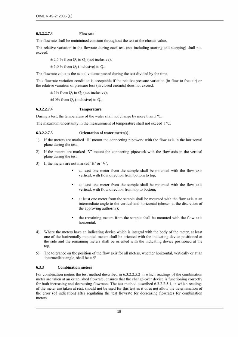
6.3.2.2.7.5 Orientation of water meter(s)
1) If the meters are marked ‘H’ mount the connecting pipework with the flow axis in the horizontal plane during the test.
2) If the meters are marked ‘V’ mount the connecting pipework with the flow axis in the vertical plane during the test.
3) If the meters are not marked ‘H’ or ‘V’,
at least one meter from the sample shall be mounted with the flow axis vertical, with flow direction from bottom to top;
at least one meter from the sample shall be mounted with the flow axis vertical, with flow direction from top to bottom;
at least one meter from the sample shall be mounted with the flow axis at an intermediate angle to the vertical and horizontal (chosen at the discretion of the approving authority);
the remaining meters from the sample shall be mounted with the flow axis horizontal.
4) Where the meters have an indicating device which is integral with the body of the meter, at least one of the horizontally mounted meters shall be oriented with the indicating device positioned at the side and the remaining meters shall be oriented with the indicating device positioned at the top.
5) The tolerance on the position of the flow axis for all meters, whether horizontal, vertically or at an intermediate angle, shall be ± 5°.
6.3.3 Combination meters
For combination meters the test method described in 6.3.2.2.5.2 in which readings of the combination meter are taken at an established flowrate, ensures that the change-over device is functioning correctly for both increasing and decreasing flowrates. The test method described 6.3.2.2.5.1, in which readings of the meter are taken at rest, should not be used for this test as it does not allow the determination of the error (of indication) after regulating the test flowrate for decreasing flowrates for combination meters.

OIML R 49-2: 2006 (E)
19
6.3.3.1 Combination meter change-over flowrate, Qxc
Change-over flowrate Qx1 is when flow stops in the larger meter with decreasing flowrate.
Change-over flowrate Qx2 is when flow starts in the larger meter with increasing flowrate.
6.3.3.2 Test method for the determination of change-over flowrates (R 49-1, 6.2.4.1)
1) Starting from a flowrate that is less than the change-over flowrate Qx2, the flowrate is increased in successive steps of 5 % until the flowrate Qx2 is achieved as defined in 6.3.3.1.The value of Qx2 is taken as the average of the values of indicated flowrate just before and just after change-over occurs.
2) Starting from a flowrate that is greater than the change-over flowrate Qx1, the flowrate is decreased in successive steps of 5 % until the flowrate Qx1 as defined in 6.3.3.1 is achieved. The value of Qx1 is taken as the average of the values of indicated flowrate just before and just after change-over occurs.
3) Complete test report R 49-3, 5.2.
6.3.4 Test procedure
1) Determine the intrinsic errors (of indication) of the water meter (in the measurement of the actual volume), for at least the following flowrates, the error at each flowrate being measured twice:
a) between Q1 and 1.1 Q1 b) between 0.5 (Q1 + Q2) and 0.55 (Q1 + Q2) (only for Q2/Q1 > 1.6) c) between Q2 and 1.1 Q2 d) between 0.33 (Q2 + Q3) and 0.37 (Q2 + Q3) e) between 0.67 (Q2 + Q3) and 0.74 (Q2 + Q3) f) between 0.9 Q3 and Q3 g) between 0.95 Q4 and Q4
and for combination meters:
h) between 0.85 Qx1 and 0.95 Qx1 i) between 1.05 Qx2 and 1.15 Qx2
2) Test the water meter without its supplementary devices attached (if any).
3) During a test hold all other influence factors at reference conditions.
4) Measure the errors (of indication) at other flowrates if the shape of the error curve indicates that the mpe may be exceeded.
5) Calculate the relative error (of indication) for each flowrate in accordance with Annex B.
6) Complete test report R 49-3, 5.3.
Notes:
1) Where the initial error curve is close to the maximum permissible error at a point other than at Q1, Q2 or Q3, if this error is shown to be typical of the meter type, the approving authority may choose to define an alternative flowrate for verification to be included in the type approval certificate.
2) Where a meter, with temperature class T70 and above, is submitted for type approval, the meter shall be tested at the reference temperature(s) given in Table 1, R 49-1. The MPE appropriate to the test temperature shall apply.
6.3.5 Acceptance criteria
1) The relative errors (of indication) observed for each of the flowrates shall not exceed the maximum permissible errors given in 3.2.1 or 3.2.2 of R 49-1. If the error observed on one or more meters is greater than the maximum permissible error at one flowrate only, the test at that

OIML R 49-2: 2006 (E)
20
flowrate shall be repeated. The test shall be declared satisfactory if two out of the three results lie within the maximum permissible error and the arithmetic mean of the results for the three tests at that flowrate is less than or equal to the maximum permissible error.
2) If all the relative errors (of indication) of the water meter have the same sign, at least one of the errors shall not exceed one half of the maximum permissible error. In all cases this requirement shall be applied equitably with respect to the water supplier and the consumer (see also R 49-1, subclause 3.3.3, paragraphs 3 and 8).
6.4 Water temperature test (R 49-1, 3.2.7)
6.4.1 Object of the test
To measure the effects of water temperature on the errors (of indication) of the meter.
6.4.2 Preparation
Apply the installation and operational requirements described in 6.3.2.
6.4.3 Test procedure
1) Measure the error (of indication) of at least one meter at the flowrate Q2 with the inlet temperatures held at 10 °C ± 5 °C for temperature classes T30 to T180 and 30 °C (+ 5 °C, – 0 °C) for temperature classes T30/70 to T30/180. All other influence factors maintained at reference conditions.
2) Measure the error (of indication) of at least one meter at the flowrate Q2 with the inlet temperatures held at the maximum admissible temperature (MAT) (Table 1, R 49-1) of the meter with a tolerance of +0 °C, – 5 °C and all other influence factors maintained at reference conditions.
3) Calculate the relative error (of indication) for each inlet water temperature in accordance with Annex B.
4) Complete test report R 49-3, 5.4.
6.4.4 Acceptance criteria
The relative error (of indication) of the meter shall not exceed the applicable maximum permissible error.
6.5 Water pressure test (R 49-1, 3.2.7)
6.5.1 Object of the test
To measure the effects of internal water pressure on the errors (of indication) of the meter.
6.5.2 Preparation
The installation and operational requirements described in 6.3.2 shall apply.
6.5.3 Test procedure
1) Measure the error (of indication) of at least one meter at a flowrate of Q2 with the inlet pressure held firstly at 0.03 MPa (0.3 bar) ± 5 % and then at the maximum admissible pressure (MAP) (+ 0, – 10 %).
2) During each test, all other influence factors shall be maintained at reference conditions.
3) Calculate the relative error (of indication) for each inlet water pressure in accordance with Annex B.
4) Complete test report R 49-3, 5.5.

OIML R 49-2: 2006 (E)
21
6.5.4 Acceptance criteria
The relative errors (of indication) of the meter shall not exceed the applicable maximum permissible error.
6.6 Flow reversal test (R 49-1, 3.2.6)
6.6.1 Object of the test
To verify that the meter satisfies the requirement of 3.2.6 in R 49-1 when flow reversals occur.
Meters which are designed to measure reverse flow must decrement the reverse flow volume accurately.
Meters which allow reverse flow but which are not designed to measure it must be subjected to reverse flow and the errors are subsequently measured for forward flow to ensure that there is no degradation in metrological performance caused by flow reversals.
Meters which are designed to prevent reverse flow (e.g. by means of an integral non-return valve) are subjected to the application of the maximum admissible pressure of the meter applied to the outlet connection and the measurement errors are subsequently measured for forward flow to ensure that there is no degradation in metrological performance caused by the pressure acting on the meter.
6.6.2 Preparation
The installation and operational requirements described in 6.3.2 shall apply.
6.6.3 Test procedure
6.6.3.1 Meters designed to measure reverse flow
1) Measure the error (of indication) of at least one meter at each of the following reverse flowrates:
a) Between Q1 and 1.1 Q1 b) Between Q2 and 1.1 Q2 c) Between 0.9 Q3 and Q3
2) During each test, all other influence factors shall be maintained at reference conditions.
3) Calculate the relative error (of indication) for each flowrate in accordance with Annex B.
4) Complete test report R 49-3, 5.6.1.
6.6.3.2 Meters not designed to measure reverse flow
1) Subject the meter to a reverse flow of 0.9 Q3 for 1 minute.
2) Measure the error (of indication) of at least one meter at the following forward flowrates:
a) Between Q1 and 1.1 Q1 b) Between Q2 and 1.1 Q2 c) Between 0.9 Q3 and Q3
3) During each test, all other influence factors shall be maintained at reference conditions.
4) Calculate the relative error (of indication) for each flowrate in accordance with Annex B.
5) Complete test report R 49-3, 5.6.2.
6.6.3.3 Meters which prevent reverse flow
1) Meters which prevent reverse flow should be subjected to the maximum admissible pressure in the reverse flow direction for 1 minute.
2) Measure the error (of indication) of at least one meter at the following forward flowrates:
a) between Q1, and 1.1 Q1 b) between Q2 and 1.1 Q2 c) between 0.9 Q3 and Q3

OIML R 49-2: 2006 (E)
22
3) During each test, all other influence factors shall be maintained at reference conditions.
4) Calculate the relative error (of indication) for each flowrate in accordance with Annex B.
5) Complete test report R 49-3, 5.6.3.
6.6.4 Acceptance criteria
In the tests described in 6.6.3.1, 6.6.3.2 and 6.6.3.3, the relative error (of indication) of the meter shall not exceed the applicable maximum permissible error
6.7 Pressure loss test (R 49-1, 6.2.6)
6.7.1 Object of the test
To determine the maximum pressure loss through the water meter at any flowrate between Q1 and Q3. To verify the maximum pressure loss is less than 0.063 MPa (0.63 bar). The pressure loss is defined as the pressure lost by the flowing fluid passing through the water meter under test, the water meter consisting of the meter, associated manifolds (for concentric meters) and connections but excluding the pipework making up the test section.
6.7.2 Equipment for pressure loss test
The equipment needed to carry out pressure loss tests consists of a measuring section of pipework containing the water meter under test and means for producing the stipulated constant flowrate through the meter. The same constant flowrate means as that employed for the measuring of the errors (of indication), described in 6.3.2, is generally used for pressure-loss tests. The upstream and downstream pipe lengths, with their end connections and pressure tappings, plus the water meter on test, constitute the measuring section. Pressure tappings of similar design and dimensions shall be fitted to the inlet and outlet pipes of the measuring section. Pressure tappings should be drilled at right angles to the pipe wall at the appropriate point. Tappings should be approximately 0.08 D but not be more than 4 mm or less than 2 mm in diameter. The diameter of the holes shall remain constant for a distance of not less than two tapping diameters before breaking into the pipe. The holes drilled through the pipe wall shall be free from burrs at the edges where they break through into the inlet and outlet pipe bores. Edges shall be sharp with neither a radius nor a chamfer. A single pressure tapping may be provided and would be suitable for most tests. To provide more robust data, four or more pressure tappings can be fitted around the pipe circumference in each measurement plane. These would be interconnected as a ‘ring’ by means of tee-shaped connectors forming an annulus to give a true mean static pressure at the pipe cross section. A similar fabricated annulus can be engineered for small diameter pipes. Guidance in the design of pressure tappings is given in Annex H. The meter shall be installed in accordance with the manufacturer’s instructions and the upstream and downstream connecting pipes in contact with the water meter shall have the same internal nominal diameter matched to the relevant meter connection. A difference in the diameter of the connecting pipes and that of the meter may result in an incorrect measurement.
The upstream and downstream pipes should be round and of smooth bore to minimize pressure loss in the pipe. The minimum dimensions for installing the tappings are shown in Fig. 1. The upstream tapping should be positioned a distance at least 10 pipe diameters downstream of the entrance to avoid errors being introduced by the entry connection and be positioned at least 5 pipe diameters upstream of the meter to avoid any errors introduced by the entry to the meter. The downstream tapping should be at least 10 diameters downstream of the meter to allow pressure to recover following any restrictions within the meter and at least 5 diameters upstream of the end of the test section to avoid any effect of downstream fittings. These specifications give minimum lengths and longer lengths are acceptable in all cases.

OIML R 49-2: 2006 (E)
23
Minimum Pipe lengths: LUP and LDN ≥ 15D LUP1 and LDN1 ≥ 10D LUP2 and LDN2 ≥ 5D
Flow direction
Water meter
LDNLUP
Measuring section
LUP1 LUP2LDN1
L
∆P
PUP PDNM
LDN2
DD
Fig 1: Pressure loss test; Layout of measuring section
PUP and PDN are planes of the pressure tappings M is the water meter
Differential Pressure measuring device
Minimum Pipe lengths: LUP and LDN ≥ 15D LUP1 and LDN1 ≥ 10D LUP2 and LDN2 ≥ 5D
Flow direction
Water meter
LDNLUP
Measuring section
LUP1 LUP2LDN1
L
∆P
PUPPUP PDNPDNMM
LDN2
DD
Fig 1: Pressure loss test; Layout of measuring section
PUP and PDN are planes of the pressure tappings M is the water meter
Differential Pressure measuring device
Longer distances may be acceptable but excessive pressure loss due to long lengths of pipe is to be avoided.
Each group of pressure tappings in the same plane shall be connected by a leak-free tube to one side of a differential pressure measuring device, e.g. a differential pressure transmitter or manometer. Provision shall be made for clearing air from the measuring device and connecting tubes. The differential pressure device must have an uncertainty allowing the determination of pressure loss with an expanded uncertainty of not more than 5 % (k = 2).
6.7.3 Test procedure
6.7.3.1 Determination of installed pressure loss
The meter should be installed in the measuring section in the test facility. Flow is established and all air purged from the test section. Adequate back pressure should be assured at the downstream pressure tapping at the maximum flowrate Q3. The test should be carried out at the defined reference pressure or as a minimum a static pressure downstream of the meter under test of 100 kPa is recommended to avoid cavitation or air release. All air should be removed from the pressure tappings and transmitter connecting pipes. The fluid should be allowed to stabilize at the required temperature.
While monitoring the differential pressure, the flow should be varied between Q1 and Q3. The flowrate showing the largest pressure loss, Qt, should be noted along with the measured pressure loss and fluid temperature. Normally Qt will be found to be equal to Q3.

OIML R 49-2: 2006 (E)
24
6.7.3.2 Determination of pressure loss attributable to test section
As some pressure will be lost due to friction in the test-section pipe between the pressure tappings, this should be determined and subtracted from the measured pressure loss across the meter. If the pipe diameter, roughness and length between the tappings is known, the pressure loss may be calculated from standard pressure loss formulae.
It may, however, be more effective to measure the pressure loss across the pipes. The test section can be re-arranged as shown in Fig. 2.
This is done by joining the upstream and downstream pipe faces together in the absence of the meter (carefully avoiding joint protrusion into the pipe bore or misalignment of the two faces), and measuring the pressure loss of the pipe measuring section for the specified flowrate).
Note: The absence of the water meter will shorten the measuring section. If telescopic sections are not fitted on the test rig, the gap may be filled by inserting downstream of the measuring section either a temporary pipe of the same length as the water meter, or the water meter itself.
The pressure loss test is repeated at the previously determined flowrate Qt.
Measure the pressure loss for the pipe lengths at the previously determined flowrate within the range.
LDNLUP
Measuring sectionL
∆P
LUP1 LUP2
PUP
LDN1
PDN
LDN2
DD
Temporary Pipe or the water meter
Fig 2: Pressure loss test; Pipe pressure loss
Flow direction
LDNLUP
Measuring sectionL
∆P
LUP1 LUP2
PUP
LDN1
PDN
LDN2
DDD
Temporary Pipe or the water meter
Fig 2: Pressure loss test; Pipe pressure loss
Flow direction
6.7.4 Calculation of the actual ∆P of a water meter
Calculate the pressure loss (∆Pt) of the water meter at (Qt) by making the subtraction ∆Pt = ∆Pm+p – ∆Pp where ∆Pm+p is the measured pressure loss at Qt with the meter in place. ∆Pp is the pressure loss measured without the meter at Qt.
If the measured flowrate either during the test or during the determination of the pipe pressure loss is not equal to the selected test flowrate, the measured pressure loss can be corrected to that expected at Qt by reference to the square law formula as follows:

OIML R 49-2: 2006 (E)
25
( )( )
( )losspressuremeasuredflowratemeasured
QQatlossPressure t
t ×= 2
2
Note that the pipe pressure loss and the meter + pipe pressure loss must be corrected to the same flowrate before the meter pressure loss ∆P is calculated. Complete test report R 49-3, 5.7. Note the water temperature, ∆P, and Qt.
6.7.5 Acceptability criteria
The pressure loss should be measured with a maximum expanded uncertainty of 5 %, with a coverage factor of k = 2.
The pressure loss of the meter shall not exceed 0.063 MPa (0.63 bar) at any flowrate between Q1 and Q3 inclusive.
6.8 Flow disturbance tests (R 49-1, 5.3.4)
6.8.1 Object of the tests
To verify that the meter complies with the requirements of 5.3.4 in R 49-1 for forward flow and where appropriate for reverse flow (see R 49-1, 3.2.6).
Notes:
1) The effects on the error (of indication) of a water meter, of the presence of specified, common types of disturbed flow upstream and downstream of the meter are measured.
2) Types 1 and 2 flow disturbers are used in tests to create left-handed (sinistrorsal) and right-handed (dextrorsal), rotational velocity fields (swirl), respectively. The flow disturbance is of a type usually found downstream of two 90° bends directly connected at right angles. A Type 3 disturbance device creates an asymmetric velocity profile usually found downstream of a protruding pipe joint, single bend or a gate valve not fully opened.
6.8.2 Preparation
In addition to the installation and operational requirements described in 6.3.2, the conditions described in 6.8.3 shall be applied.
6.8.3 Test procedure
1) Using the Types 1, 2 and 3 flow disturbers specified in ISO 4064, Part 3 [6], determine the error (of indication) of the meter at a flowrate between 0.9 Q3 and Q3, for each of the installation conditions shown in Annex C.
2) During each test, all other influence factors shall be maintained at reference conditions.
3) Complete test report R 49-3, 5.8.
Additional requirements
a) For meters where the manufacturer has specified installation lengths of straight pipe of at least 15 × DN upstream and 5 × DN downstream of the meter, no external flow straighteners are allowed.
b) When a minimum straight pipe length of 5 × DN downstream of the meter is specified by the manufacturer, only tests 1, 3 and 5 shown in Annex C shall be performed.
c) Where meter installations with external flow straighteners are to be used, the manufacturer shall specify the straightener model, its technical characteristics and its position in the installation relative to the water meter.
d) Devices within the water meter having flow straightening functions shall not be considered to be a “straightener” in the context of these tests.

OIML R 49-2: 2006 (E)
26
e) Some types of water meter which have been proven to be unaffected by flow disturbances upstream and downstream of the meter may be exempted from this test by the approving authority.
6.8.4 Acceptance criteria
The relative error (of indication) of the meter shall not exceed the applicable maximum permissible error for any of the flow disturbance tests.
6.9 Endurance tests (R 49-1, 6.2.7)
During endurance tests, the rated operating conditions of the meter shall be met. Where a combination meter consists of individual meters that have been previously approved, only the discontinuous Combination meters (additional test) (Table 2) is required.
6.9.1 Discontinuous flow test
6.9.1.1 Object of the test
To verify that the water meter is durable when subjected to cyclic flow conditions.
This test is applied only to meters with Q3 ≤ 16 m3/h.
The test consists of subjecting the meter to the specified number of starting and stopping flowrate cycles of short duration, the constant test flowrate phase of each cycle being kept at the specified flowrate (Q3) throughout the duration of the test (see 6.9.1.3.1).
For the convenience of laboratories, the test can be divided up into periods of at least 6 h.
6.9.1.2 Preparation
6.9.1.2.1 Description of the installation
The installation consists of:
a) a water supply (non-pressurized, pressurized tank; pump; etc.); b) pipework.
6.9.1.2.2 Pipework
The meters can be arranged in series or in parallel, or the two systems can be combined.
In addition to the meter(s), the piping system consists of:
a) one flow-regulating device (per line of meters in series, if necessary); b) one or more isolating valves; c) a device for measuring the temperature of the water upstream of the meters; d) devices for checking: the flowrate, the duration of cycles and the number of
cycles; e) one flow-interrupting device for each line of meters in series; f) devices for measuring pressure at the inlet and outlet.
The various devices shall not cause cavitation phenomena or other types of parasitic wear of the meter(s).
6.9.1.2.3 Precautions to be taken
The meter(s) and connecting pipes shall be suitably bled of air.
The flow variation during the repeated opening and closing operations shall be progressive, so as to prevent water hammer.

OIML R 49-2: 2006 (E)
27
6.9.1.2.4 Flowrate cycle
A complete cycle comprises the following four phases:
a) a period from zero to the test flowrate; b) a period at constant test flowrate; c) a period from the test flowrate to zero; d) a period at zero flowrate.
6.9.1.3 Test procedure
1) Before commencing the discontinuous endurance test, measure the errors (of indication) of the meter(s) as described in 6.3 and at the same flowrates as in 6.3.4.
2) Mount the meters either singly or in groups in the test rig in the same orientations as those used in determination of the intrinsic errors (of indication) (6.3.2.2.7.5).
3) During the tests, maintain the meters within their rated operating conditions and with the pressure downstream of the meters high enough to prevent cavitation in the meters.
4) Adjust the flowrate to within the specified tolerances.
5) Run the meter(s) at the conditions shown in Table 2.
6) Following the discontinuous endurance test, measure the final errors (of indication) of the meters as described in 6.3 and at the same flowrates as in 6.3.4.
7) Calculate the final relative error (of indication) for each flowrate in accordance with Annex B.
8) For each flowrate, subtract the value of the intrinsic error (of indication) obtained before the test (step 1) from the error (of indication) obtained after the test (step 7).
9) Complete test report R 49-3, 5.9.1.
6.9.1.3.1 Tolerance on flowrate
The relative variation of the flow values shall not exceed ± 10 % outside the opening, closing and stoppage periods. The meter(s) on test may be used to check the flowrate.
6.9.1.3.2 Tolerance on test timing
The tolerance on the specified duration of each phase of the flow cycle shall not exceed ± 10 %.
The tolerance on the total test duration shall not exceed ± 5 %.
6.9.1.3.3 Tolerance on the number of cycles
The number of cycles shall not be less than that stipulated, but shall not exceed this number by more than 1 %.
6.9.1.3.4 Tolerance on discharged volume
The volume discharged throughout the test shall be equal to half the product of the specified test flowrate and the total theoretical duration of the test (operating periods plus transient and stoppage periods) with a tolerance of ± 5 %.
This precision can be obtained by sufficiently frequent corrections of the instantaneous flows and operating periods.
OIML R 49-2: 2006 (E)
28
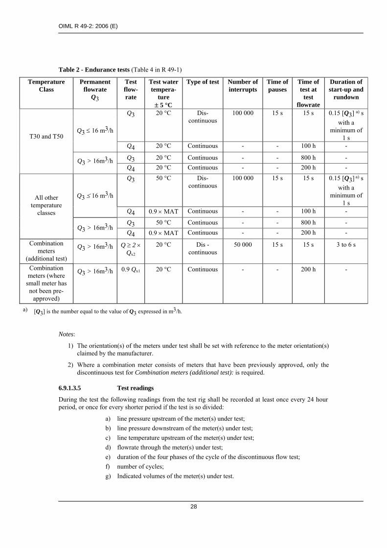
Table 2 - Endurance tests (Table 4 in R 49-1)
Temperature Class
Permanent flowrate
Q3
Test flow- rate
Test water tempera-
ture ± 5 °C
Type of test Number of interrupts
Time of pauses
Time of test at
test flowrate
Duration of start-up and
rundown
Q3 20 °C Dis-continuous
100 000 15 s 15 s 0.15 [Q3] a) s with a
minimum of 1 s
Q3 ≤ 16 m3/h
Q4 20 °C Continuous - - 100 h -
Q3 20 °C Continuous - - 800 h -
T30 and T50
Q3 > 16m3/h Q4 20 °C Continuous - - 200 h - Q3 50 °C Dis-
continuous 100 000 15 s 15 s 0.15 [Q3] a) s
with a minimum of
1 s Q3 ≤ 16 m3/h
Q4 0.9 × MAT Continuous - - 100 h -
Q3 50 °C Continuous - - 800 h -
All other temperature
classes
Q3 > 16m3/h Q4 0.9 × MAT Continuous - - 200 h -
Combination meters
(additional test)
Q3 > 16m3/h Q ≥ 2 × Qx2
20 °C Dis -continuous
50 000 15 s 15 s 3 to 6 s
Combination meters (where
small meter has not been pre-
approved)
Q3 > 16m3/h 0.9 Qx1 20 °C Continuous - - 200 h -
a) [Q3] is the number equal to the value of Q3 expressed in m3/h.
Notes:
1) The orientation(s) of the meters under test shall be set with reference to the meter orientation(s) claimed by the manufacturer.
2) Where a combination meter consists of meters that have been previously approved, only the discontinuous test for Combination meters (additional test): is required.
6.9.1.3.5 Test readings
During the test the following readings from the test rig shall be recorded at least once every 24 hour period, or once for every shorter period if the test is so divided:
a) line pressure upstream of the meter(s) under test; b) line pressure downstream of the meter(s) under test; c) line temperature upstream of the meter(s) under test; d) flowrate through the meter(s) under test; e) duration of the four phases of the cycle of the discontinuous flow test; f) number of cycles; g) Indicated volumes of the meter(s) under test.
OIML R 49-2: 2006 (E)
29
6.9.1.4 Acceptance criteria
After the discontinuous endurance test:
1) the variation in the error curve shall not exceed 3 % for flowrates in the lower zone (Q1 ≤ Q < Q2), or 1.5 % for flowrates in the upper zone (Q2 ≤ Q ≤ Q4). For the purpose of determining these requirements the mean values of the errors (of indication) at each flowrate shall apply.
2) the curves shall not exceed a maximum error limit of:
± 6 % for flowrates in the lower zone (Q1 ≤ Q < Q2), and
± 2.5 % for flowrates in the upper zone (Q2 ≤ Q ≤ Q4) for meters intended to meter water with a temperature between 0.1 °C and 30 °C, or
± 3.5 % for flowrates in the upper zone (Q2 ≤ Q ≤ Q4) for meters intended to meter water with a temperature greater than 30 °C.
6.9.2 Continuous flow test
6.9.2.1 Object of the test
To verify the durability (see T.16 in [29]) of the water meter when subjected to continuous, permanent and overload flow conditions.
The test consists of subjecting the meter to constant flowrate of Q3 or Q4 for a specified duration. In addition, where the small meter of a combination meter has not been pre-approved, the combination meter shall be subjected to a continuous flow test as shown in Table 2.
For the convenience of laboratories, the test can be divided up into periods of at least 6 h.
6.9.2.2 Preparation
6.9.2.2.1 Description of the installation
The installation consists of:
a) a water supply (non-pressurized or pressurized tank, pump, etc.); b) pipework.
6.9.2.2.2 Pipework
In addition to the meter(s) to be tested, the pipework comprises:
a) a flow-regulating device; b) one or more isolating valves; c) a device for measuring the water temperature at the meter inlet; d) means for checking the flowrate and duration of the test; e) devices for measuring pressure at the inlet and outlet.
The different devices shall not cause cavitation phenomena or other types of parasitic wear of the meter(s).
6.9.2.2.3 Precautions to be taken
The meter and connecting pipes shall be suitably bled of air.
6.9.2.3 Test procedure
1) Before commencing the continuous endurance test, measure the errors (of indication) of the meter(s) as described in 6.3 and at the same flowrates as in 6.3.4.
2) Mount the meter(s) either singly or in groups in the test rig in the same orientations as those used in the determination of the intrinsic error (of indication) tests (6.3.2.2.7.5).

OIML R 49-2: 2006 (E)
30
3) Carry out the following tests:
a) For meters with Q3 ≤ 16 m3/h, run the meter(s) at a flowrate of Q4 for a period of 100 hours;
b) For meters with Q3 > 16 m3/h, run the meter(s) at a flowrate of Q3 for a period of 800 hours then at Q4 for a period of 200 hours;
c) For combination meters where the small meter has not been pre-approved, run the meter(s) at a flowrate of 0.9 Qx1 for a period of 200 hours.
4) Throughout the endurance tests the meter(s) shall be held within their rated operating conditions and the pressure at the outlet of each meter shall be high enough to prevent cavitation.
5) After each continuous endurance test, measure the errors (of indication) of the meter(s) as described in 6.3 and at the same flowrates.
6) Calculate the relative error (of indication) for each flowrate in accordance with Annex B.
7) For each flowrate, subtract the error (of indication) obtained before the test (step 1) from the error (of indication) obtained after the test (step 6).
8) Complete test report R 49-3, 5.9.2.
6.9.2.3.1 Tolerance on flowrate
The flowrate shall be kept constant throughout the test at a predetermined level.
The relative variation of the flowrate values during each test shall not exceed ± 10 % (except when starting and stopping).
6.9.2.3.2 Tolerance on test timing
The specified duration of the test is a minimum value.
6.9.2.3.3 Tolerance on discharged volume
The volume indicated at the end of the test shall not be less than that determined from the product of the specified test flowrate and the specified duration of the test.
To satisfy this condition, sufficiently frequent corrections to the flowrate shall be made. The water meter(s) on test may be used to check the flowrate.
6.9.2.3.4 Test readings
During the test the following readings from the test rig shall be recorded at least once every 24 hour period, or once for every shorter period if the test is so divided:
a) water pressure upstream of the meter(s) under test; b) water pressure downstream of the meter(s) under test; c) water temperature upstream of the meter(s) under test; d) flowrate through the meter(s) under test; e) indicated volume of the meter(s) under test.
6.9.2.4 Acceptance criteria
After the continuous endurance test:
For accuracy class 1 water meters:
1) The variation in the error curve shall not exceed 2 % for flowrates in the lower zone (Q1 ≤ Q < Q2), and 1 % for flowrates in the upper zone (Q2 ≤ Q ≤ Q4). For the purpose of determining these requirements the mean values of the errors (of indication) at each flowrate, shall apply.

OIML R 49-2: 2006 (E)
31
2) The curves shall not exceed a maximum error limit of ± 4 % for flowrates in the lower zone (Q1 ≤ Q < Q2) and ± 1.5 % for flowrates in the upper zone (Q2 ≤ Q ≤ Q4) for meters of temperature class T30 and ± 2.5 % for all other temperature classes.
For accuracy class 2 water meters:
1) The variation in the error curve shall not exceed 3 % for flowrates in the lower zone (Q1 ≤ Q < Q2), and 1.5 % for flowrates in the upper zone (Q2 ≤ Q ≤ Q4). For the purpose of determining these requirements the mean values of the errors (of indication) at each flowrate, shall apply.
2) The curves shall not exceed a maximum error limit of:
± 6 % for flowrates in the lower zone (Q1 ≤ Q < Q2), and ± 2.5 % for flowrates in the upper zone (Q2 ≤ Q ≤ Q4) ± 2.5 % for flowrates in the upper
zone (Q2 ≤ Q ≤ Q4) for meters intended to meter water with a temperature between 0.1 °C and 30 °C, or
± 3.5 % for flowrates in the upper zone (Q2 ≤ Q ≤ Q4) for meters intended to meter water with a temperature greater than 30 °C.
6.9.3 Specific test for combination meters
After the test described in 6.9.2.3, the combination meter shall undergo an endurance test simulating service conditions under the following conditions:
a) Test flowrate: at least twice the changeover flowrate Qx2 (determined using increasing flowrate);
b) Type test: discontinuous; c) Number of interruptions: 50 000; d) Duration of stop: 15 s; e) Duration of running at test flowrate: 15 s; f) Duration of acceleration and deceleration: minimum 3 s, maximum 6 s.
Complete test report R 49-3, 5.9.3.
6.9.3.1 Acceptance criteria
After the cyclic endurance test
For accuracy class 1 water meters:
1) The variation in the error curve shall not exceed 2 % for flowrates in the lower zone (Q1 ≤ Q < Q2), and 1 % for flowrates in the upper zone (Q2 ≤ Q ≤ Q4). For the purpose of determining these requirements the mean values of the errors (of indication) at each flowrate, shall apply.
2) The curves shall not exceed a maximum error limit of ± 4 % for flowrates in the lower zone (Q1 ≤ Q < Q2) and ± 1.5 % for flowrates in the upper zone (Q2 ≤ Q ≤ Q4) for meters of temperature class T30 and ± 2.5 % for all other temperature classes.
For accuracy class 2 water meters:
1) The variation in the error curve shall not exceed 3 % for flowrates in the lower zone (Q1 ≤ Q < Q2), and 1.5 % for flowrates in the upper zone (Q2 ≤ Q ≤ Q4). For the purpose of determining these requirements the mean values of the errors (of indication) at each flowrate, shall apply.
2) The curves shall not exceed a maximum error limit of:
± 6 % for flowrates in the lower zone (Q1 ≤ Q < Q2), and
± 2.5 % for flowrates in the upper zone (Q2 ≤ Q ≤ Q4) ± 2.5 % for flowrates in the upper zone (Q2 ≤ Q ≤ Q4) for meters intended to meter water with a temperature between 0.1 °C and 30 °C, or

OIML R 49-2: 2006 (E)
32
± 3.5 % for flowrates in the upper zone (Q2 ≤ Q ≤ Q4) for meters intended to meter water with a temperature greater than 30 °C.
6.10 6.10 Magnetic field testing
All water meters where the mechanical components may be influenced by a static magnetic field (e.g. equipped with a magnetic coupling in the drive to the readout) and all meters with electronic components shall be tested to show that the water meter is able to withstand the influence of a static magnetic field. This shall be tested according to the provisions of section 7.12.
6.11 Environmental testing
Depending on the meter technology and construction, levels of testing to meet environmental conditions. The relevant tests specified in R 49-1 Annex A and R 49-2 sections 7.2, 7.3, and 7.4 shall be applied as appropriate. It is specified in R 49-2 section 7.1.7 that these tests do not apply to meters of purely mechanical construction.
7 Performance tests related to influence quantities and disturbances 7.1 General requirements (R 49-1, A.1)
This section defines the performance tests which are intended to verify that water meters perform and function as intended in a specified environment and under specified conditions. Each test indicates, where appropriate, the reference conditions for determining the intrinsic error.
These performance tests are additional to the tests described in section 6 and apply to complete meters, to separable parts of a water meter, and, if required, to ancillary devices. The tests are required depending on the class of meter as described in section 7.1.1 and the type of meter construction or design as described in section 7.1.7.
When the effect of one influence quantity is being evaluated, all other influence quantities are to be held at the reference conditions (see section 3).
The type approval tests specified in this section may be carried out in parallel with the tests specified in section 6, using examples of the same model of the water meter, or its separable parts.
7.1.1 Environmental classification (R 49-1, A.2)
For each performance test, typical test conditions are indicated; they correspond to the mechanical, electrical and climatic environmental conditions to which water meters are exposed.
Water meters with electronic devices are divided into three classes according to these environmental conditions:
Class B for fixed meters installed in a building; Class C for fixed meters installed outdoors; Class I for mobile meters.
The applicant for type approval may also indicate specific environmental conditions in the documentation supplied to the approving authority, based on the intended use of the meter. In this case, the approving authority will carry out performance tests at severity levels corresponding to these environmental conditions. These severity levels must not be less than Class B. (Reference R 49-1 Table A.1).
In all cases the approving authority shall verify that the conditions of use are met.
Note: Meters which are approved at a given severity level are also suitable for lower severity levels.
7.1.2 Electromagnetic environment (R 49-1, A.3)
Water meters with electronic devices are divided into two electromagnetic environment classes:
Class E1 Residential, commercial and light industrial; Class E2 Industrial.

OIML R 49-2: 2006 (E)
33
7.1.3 Reference conditions (R 49-1, 6.1 and A.4)
Reference conditions are listed in clause 3.
7.1.4 Test volumes for measuring error (of indication) of a water meter (R 49-1, A.6.1)
Some influence quantities should have a constant effect on the error of indication of a water meter and not a proportional effect related to the measured volume.
In other tests the effect of the influence quantity applied to a water meter is related to the measured volume. In these cases, in order to be able to compare results obtained in different laboratories, the test volume for measuring the error of indication of the meter shall correspond to that delivered in one minute at the over-load flowrate Q4.
However, some tests may require more than one minute, in which case they shall be carried out in the shortest possible time, taking into consideration the measurement uncertainty.
7.1.5 Influence of the water temperature (R 49-1, A.6.1-A.6.3)
Dry heat, cold and damp heat tests are concerned with measuring the effects of ambient air temperature on the performance of the meter. However, the presence of the measurement transducer, filled with water, may also influence heat dissipation in electronic components.
If the meter has a value of Q3 ≤ 16m3/h, the meter should have water passing through it at the reference flowrate and the error (of indication) of the meter shall be measured with the electronic parts and the measurement transducer subjected to the reference conditions.
Optionally, a simulation of the measurement transducer may be used for testing all electronic components. Where simulated tests are used, they shall replicate the effects caused by the presence of water for those electronic devices which are normally attached to the flow sensor, and the reference conditions shall be applied during the tests.
7.1.6 Requirements for environmental tests
The following requirements are associated with the environmental tests and the relevant IEC standards to be applied are listed in the appropriate sections of this Recommendation:
a) preconditioning of the EUT; b) any deviations in the procedure from the relevant IEC standard; c) initial measurements; d) state of the EUT during conditioning; e) severity levels, values of the influence factor and duration of exposure; f) measurements required and/or the loading during conditioning; g) recovery of the EUT; h) final measurements; i) the acceptance criteria for the EUT passing a test.
Where no IEC standard exists for a specific test, the essential requirements for the test are given in this Recommendation.
7.1.7 Equipment under test (EUT) (R 49-1, 6.2.12.3)
For the purpose of testing, the EUT shall be categorized as one of the cases, A to E, according to the technology described in sections 7.1.7.1 to 7.1.7.4 and the following requirements shall apply:
Case A No performance test (as mentioned in this section) is required.
Case B The EUT is the complete meter or combined meter: the test shall be carried out with water flowing in the volume or flow sensor and the meter operating as designed.
Case C The EUT is the measurement transducer (including flow or volume sensor): the test shall be carried out with water flowing in the volume or flow sensor and the meter operating as designed.
OIML R 49-2: 2006 (E)
34
Case D The EUT is the electronic calculator (including the indicating device) or the ancillary device: the test shall be carried out with water flowing in the volume or flow sensor and the meter operating as designed.
Case E The EUT is the electronic calculator (including the indicating device) or the ancillary device: the test may be carried out with simulated measurement signals without water in the volume or flow sensor.
Note: The approving authority may apply an appropriate category, A to E, for approval testing of meters having technology which is not included in 7.1.7.1 to 7.1.7.4.
7.1.7.1 Positive displacement meters and turbine water meters
a) The meter is not fitted with electronic devices: Case A b) The measurement transducer and the electronic calculator including the
indicating device are in the same housing: Case B c) The measurement transducer is separate from the electronic calculator, but not
fitted with electronic devices: Case A d) The measurement transducer is separate from the electronic calculator, and fitted
with electronic devices: Case C e) The electronic calculator including the indicating device is separate from the
measurement transducer and simulation of the measurement signals is not possible: Case D
f) The electronic calculator including the indicating device is separate from the measurement transducer and simulation of the measurement signals is possible: Case E
7.1.7.2 Electromagnetic water meters
a) The measurement transducer and the electronic calculator including the indicating device are in the same housing: Case B
b) The flow sensor, consisting only of the pipe, the coil and the two meter electrodes, is without any additional electronic devices: Case A
c) The measurement transducer including the flow sensor is separate from the electronic calculator and in one housing: Case C
d) The electronic calculator including the indicating device is separate from the measurement transducer and simulation of the measurement signals is not possible: Case D
7.1.7.3 Ultrasonic water meters, Coriolis water meters, fluidic water meters
a) The measurement transducer and the electronic calculator including the indicating device are in the same housing: Case B
b) The measurement transducer is separate from the electronic calculator and fitted with electronic devices: Case C
c) The electronic calculator including the indicating device is separate from the measurement transducer and simulation of the measurement signals is not possible: Case D

OIML R 49-2: 2006 (E)
35
7.1.7.4 Ancillary devices
a) The ancillary device is part of the water meter, a part of the measurement transducer or part of the electronic calculator: Cases A to E
b) The ancillary device is separate from the meter, but not fitted with electronic devices: Case A
c) The ancillary device is separate from the meter, a simulation of the input signals is not possible: Case D
d) The ancillary device is separate from the meter, a simulation of the input signals is possible: Case E
7.2 Dry heat (non-condensing) (R 49-1, A.6.1)
7.2.1 Object of the test
To verify that the EUT complies with the provisions of 3.2 in R 49-1, during the application of high ambient temperatures at the severity levels given in A.6.1 of R 49-1.
7.2.2 Preparation
The test arrangements are those described in the following publications:
IEC 60068-2-2 (1974-01), Amendments IEC 60068-2-2-am1 (1993-02) and IEC 60068-2-2-am2 (1994-05). Environmental testing. Part 2. Tests. Test B. Dry heat. Section 4 - Test Bd: Dry heat, for heat-dissipating specimen, or test Bb for non-heat dissipating specimen, with gradual change temperature [8].
Guidance on testing arrangements is given in:
IEC 60068-3-1 (1974-01). First supplement IEC 60068-3-1-1A (1978-01). Basic Environmental testing procedures. Part 3: Background information. Section 1 - Cold and dry heat tests [9].
IEC 60068-1 (1988-06). Amendment: IEC 60068-1-am1 (1992-04). Basic environmental testing. Part 1: General and guidance [10].
7.2.3 Test procedure (in brief)
1) No pre-conditioning is required.
2) Measure the error (of indication) of the EUT at the reference flowrate and at the following test conditions:
a) at the reference air temperature of 20 ± 5 °C, before conditioning the EUT; b) at an air temperature of 55 ± 2°C, after the EUT has been stabilized at this
temperature for a period of 2 hours; c) at the reference air temperature of 20 ± 5 °C, after recovery of the EUT.
3) Calculate the relative error (of indication) for each test condition in accordance with Annex B.
4) During the application of the test conditions, check that the EUT is functioning correctly.
5) Complete test report R 49-3, 6.1.
Additional requirement:
When measuring the errors (of indication), the installation and operational conditions described in 6.3.2 shall be followed and the reference conditions shall be applied unless otherwise specified.
7.2.4 Acceptance criteria
During the application of the test conditions,
1) All the functions of the EUT shall operate as designed.

OIML R 49-2: 2006 (E)
36
2) The relative error (of indication) of the EUT, at the test conditions, shall not exceed the maximum permissible error of the upper flowrate zone (see R 49-1, 3.2).
7.3 Cold (R 49-1, A.6.2)
7.3.1 Object of the test
To verify that the EUT complies with the provisions of 3.2 in R 49-1, during the application of low ambient temperatures at the severity levels given in A.6.2 of R 49-1.
7.3.2 Preparation
The testing arrangements are those described in the following publications:
IEC 60068-2-1 (1990-05). Amendments IEC 60068-2-1am1 (1993-02) and IEC 60068-2-1-am2 (1994-06). Environmental testing. Part 2.1 Tests. Test A. Cold. Section 3- Test Ad: Cold, for heat-dissipating specimen, or test Bb for non-heat dissipating specimen, with gradual change of temperature [11].
Guidance on testing arrangements is given in:
IEC 60068-3-1 (1974-01). First supplement IEC 60068-3-1-1A (1978-01). Basic Environmental testing procedures. Part 3: Background information. Section 1 - Cold and dry heat tests [9].
IEC 60068-1 (1988-06). Amendment: IEC 60068-1-am1 (1992-04). Basic environmental testing. Part 1: General and guidance [10].
7.3.3 Test procedure (in brief)
1) Do not pre-condition the EUT.
2) Measure the error (of indication) of the EUT at the reference flowrate and at the reference air temperature.
3) Stabilize the air temperature at either – 25 °C (severity level 3) or + 5 °C (severity level 1) for a period of 2 hours.
4) Measure the error (of indication) of the EUT at the reference flowrate at an air temperature of either – 25 °C (severity level 3) or + 5 °C (severity level 1).
5) After recovery of the EUT, measure the error (of indication) of the EUT at the reference flowrate and at the reference air temperature.
6) Calculate the relative error (of indication) for each test condition in accordance with Annex B.
7) During the application of the test conditions, check that the EUT is functioning correctly.
8) Complete test report R 49-3, 6.2
Additional requirements:
a) If it is necessary to have water in the flow sensor, the water temperature shall be held at the reference temperature.
b) When measuring the errors (of indication), the installation and operational conditions described in 6.3.2 shall be followed and the reference conditions shall be applied unless otherwise specified.
7.3.4 Acceptance criteria
During the application of the stabilized test conditions,
1) All the functions of the EUT shall operate as designed, and
2) The relative error (of indication) of the EUT, at the test conditions, shall not exceed the maximum permissible error of the upper flowrate zone (R 49-1, 3.2).

OIML R 49-2: 2006 (E)
37
7.4 Damp heat, cyclic (condensing) (R 49-1, A.6.3)
7.4.1 Object of the test
To verify that the EUT complies with the provisions of R 49-1 (3.2), after applying conditions of high humidity, combined with cyclic temperature changes described in A.6.3 of R 49-1.
7.4.2 Preparation
The testing arrangements are those described in the following publications:
IEC 60068-2-30 (1980-01), Amendment IEC 60068-2-30-am1 (1985-08). Basic environmental testing procedures. Part 2: Tests. Test Db and guidance: Damp heat, cyclic (12h + 12hour cycle), test variant 1 [12].
Guidance on testing arrangements is given in:
IEC 60068-3-4 (2001-08): Environmental testing. Part 3-4: Supporting documentation and guidance - Damp heat tests [13].
7.4.3 Test procedure (in brief)
The requirements for the performance of the test equipment, conditioning and recovery of the EUT, and exposure of the EUT to cyclic temperature changes under damp heat conditions, are described in IEC Publication IEC 60068-2-30 [12] and IEC 60068-3-4 [13].
The test program consists of steps 1 to 7 below.
1) Pre-condition the EUT.
2) Expose the EUT to cyclic temperature variations between the lower temperature of 25 °C and the upper temperature of 55 °C (environmental classes C and I) or 40 °C (environmental class B). Maintaining the relative humidity above 95 % during the temperature changes and during the phases at low temperature, and at 93 % at the upper temperature phases. Condensation should occur on the EUT during the temperature rise.
3) Allow the EUT to recover.
4) After recovery, check that the EUT is functioning correctly.
5) Measure the error (of indication) of the EUT at the reference flowrate.
6) Calculate the relative error (of indication) in accordance with Annex B.
7) Complete test report R 49-3, 6.3.
Additional requirements:
a) The power supply to the EUT is switched off during steps 1 to 3. b) When measuring the error (of indication), the installation and operational
conditions described in 6.3.2 shall be followed and the reference conditions shall be applied unless otherwise specified.
7.4.4 Acceptance criteria
After the application of the influence factor and recovery:
1) All the functions of the EUT shall operate as designed.
2) The relative error (of indication) of the EUT, at the reference conditions, shall not exceed the maximum permissible error of the upper flowrate zone (R 49-1, 3.2).

OIML R 49-2: 2006 (E)
38
7.5 Power voltage variation (R 49-1, A.6.4)
7.5.1 Water meters powered by direct AC or by AC/DC converters (R 49-1, A.6.4.1)
7.5.1.1 Object of the test
7.5.1.1.1 Single voltage
To verify that electronic devices which operate at a single nominal value of mains voltage (Unom) at a nominal frequency (fnom) comply with the provisions of R 49-1 (3.2), during static deviations of the AC (single-phase) mains power supply, applied in accordance with the requirements of R 49-1 (A.6.4.1).
7.5.1.1.2 Voltage range
To verify that electronic devices which operate within a nominal range of mains voltage, having an upper limit Uu and a lower limit Ul, at a nominal frequency (fnom).comply with the provisions of R 49-1 (3.2), during static deviations of the AC (single-phase) mains power supply, applied in accordance with the requirements of R 49-1 (A.6.4.1).
7.5.1.2 Preparation
The testing arrangements are those described in the following publications:
IEC 61000-4-11 (1994-06), Amendment IEC 61000-4-11-am1 (2000-11) Electromagnetic compatibility (EMC) – Part 4: Testing and measuring techniques – Section 11: Voltage dips, short interruptions and voltage variations immunity tests [14].
IEC/TR3 61000-2-1 (1990-05) Electromagnetic Compatibility (EMC) Part 2: Environment. Section 1: Description of the environment – Electromagnetic environment for low-frequency conducted disturbances and signaling in public power supply systems [15].
IEC 61000-2-2 (1990-05) Electromagnetic Compatibility (EMC) Part 2: Environment. Section 2: Compatibility levels for low-frequency conducted disturbances and signaling in public low-voltage power supply systems [16].
IEC 61000-4-1 (2000-04) Electromagnetic Compatibility (EMC) Part 4-1: Testing and measurement techniques – Overview of IEC 61000-4 series [17].
IEC 60654-2 (1979-01) -am1 (1992-10) Operating conditions for industrial process measurement and control equipment. Part 2: Power [18].
7.5.1.3 Test procedure (in brief)
1) Expose the EUT to power voltage variations, while the EUT is operating under reference conditions.
2) Measure the error (of indication) of the EUT, during the application of the upper mains voltage limit Unom + 10 % (single voltage) or Uu + 10 % (voltage range).
3) Measure the error (of indication) of the EUT, during the application of the lower mains voltage limit Unom – 15 % (single voltage) or Ul – 15 % (voltage range).
4) Calculate the relative error (of indication) for each test condition in accordance with Annex B.
5) Check that EUT is functioning correctly during the application of each power supply variation.
6) Complete test report R 49-3, 6.4.1.
Additional requirements: a) During the measurement of the error (of indication) the EUT shall be subjected
to the reference flowrate (R 49-1, 6.1). b) When measuring the errors (of indication), the installation and operational
conditions described in 6.3.2 shall be followed and the reference conditions shall be applied unless otherwise specified.

OIML R 49-2: 2006 (E)
39
7.5.1.4 Acceptance criteria
During the application of the influence factor,
1) All the functions of the EUT shall operate as designed.
2) The relative error of indication of the EUT, at the test conditions, shall not exceed the maximum permissible error of the upper flowrate zone (see R 49-1, 3.2).
7.5.2 Water meters powered by primary DC batteries (R 49-1, A.6.4.2)
7.5.2.1 Object of the test
To verify that battery powered electronic devices comply with the provisions R 49-1 (3.2) during static deviations of the DC, primary battery, power supply voltage, applied in accordance with the requirements of R 49-1 (A.6.4.2).
7.5.2.2 Preparation
No references to IEC standards for test methods can be given.
7.5.2.3 Test procedure
1) Expose the EUT to power voltage variations, while the EUT is operating under reference conditions.
2) Measure the error (of indication) of the EUT, during the application of the upper battery voltage limit Umax.
3) Measure the error (of indication) of the EUT, during the application of the lower battery voltage limit Umin.
4) Calculate the relative error (of indication) for each test condition in accordance with Annex B.
5) Check that EUT is functioning correctly during the application of each power supply variation.
6) Complete test report R 49-3, 6.4.2.
Additional requirements: a) During the measurement of the error (of indication) the EUT shall be subjected
to the reference flowrate. b) When measuring the errors (of indication), the installation and operational
conditions described in 6.3.2 shall be followed and the reference conditions shall be applied unless otherwise specified.
7.5.2.4 Acceptance criteria
During the application of the voltage variations,
1) All the functions of the EUT shall operate as designed.
2) The relative error (of indication) of the EUT at the test conditions shall not exceed the maximum permissible error of the upper flowrate zone (see R 49-1, 3.2).
7.6 Vibration (random) (R 49-1, A.6.5)
7.6.1 Object of the test
To verify that the EUT complies with the provisions of R 49-1 (3.2), after the application of random vibrations at severity level 2 (see R 49-1, A.6.5).
Note: Applicable only to meters for mobile installations.

OIML R 49-2: 2006 (E)
40
7.6.2 Preparation
The testing arrangements are those described in the following publications:
IEC 60068-2-64 (1993-05), Corr. 1 (1993-10). Environmental testing. Part 2: Test Methods - Test Fh Vibration, broad-band random (digital control) and guidance [19].
IEC 60068-2-47 (1999-10) Environmental testing. Part 2-47: Test Methods – Mounting of components, equipment and other articles for vibration, impact and similar dynamic tests [20].
7.6.3 Test procedure (in brief)
1) Mount the EUT on a rigid fixture by its normal mounting means, such that the gravitational force acts in the same direction as it would in normal use. However, if the gravitational effect is insignificant, and the meter is not marked H or V, the EUT may be mounted in any position.
2) Apply random vibrations over the frequency range of 10 to 150 Hz to the EUT, in three, mutually perpendicular axes in turn, for a period of at least 2 minutes per axis.
3) Allow the EUT a period for recovery.
4) Examine the EUT for correct functioning.
5) Measure the error (of indication) of the EUT at the reference flowrate.
6) Calculate the relative error (of indication) in accordance with Annex B.
7) Complete test report R 49-3, 6.5.
Additional requirements:
a) Where the flow sensor is included in the EUT, it shall not be filled with water during the application of the disturbance;
b) The power supply to the EUT is switched off during steps 1, 2 and 3; c) During the application of the vibrations the following conditions shall be met:
Total RMS level: 7 m.s-2
ASD level 10 to 20 Hz: 1 m2.s-3
ASD level 20 to 150 Hz: – 3 dB/octave
d) When measuring the errors (of indication) of the EUT, the installation and operational conditions described in 6.3.2 shall be followed and the reference conditions shall be applied unless otherwise specified.
7.6.4 Acceptance criteria
After the application of the vibrations and recovery:
1) All functions of the EUT shall operate as designed.
2) The relative error (of indication) of the EUT, at the test conditions, shall not exceed the maximum permissible error of the upper flowrate zone (see R 49-1, 3.2).
7.7 Mechanical shock (R 49-1, A.6.6)
7.7.1 Object of the test
To verify that the EUT complies with the provisions of 3.2 in R 49-1, after the application of the mechanical shock test (dropping onto face) at the severity level given in A.6.6 of R 49-1.
7.7.2 Preparation
The testing arrangements are those described in the following publications:

OIML R 49-2: 2006 (E)
41
IEC 60068-2-31 (1969-01) -am1 (1982-01) Environmental testing. Part 2: Tests. Test Ec: Drop and topple, primarily for equipment type specimens [21].
IEC 60068-2-47 (1999-10) Environmental testing. Part 2-47: Test Methods – Mounting of components, equipment and other articles for vibration, impact and similar dynamic tests [20].
7.7.3 Test procedure (in brief)
1) The EUT shall be placed on a rigid, level surface in its normal position of use and tilted towards one bottom edge until the opposite edge of the EUT is 50 mm above the rigid surface. However, the angle made by the bottom of the EUT and the test surface shall not exceed 30°.
2) Allow the EUT to fall freely onto the test surface.
3) Repeat steps 1 and 2 for each bottom edge.
4) Allow the EUT a period for recovery.
5) Examine the EUT for correct functioning.
6) Measure the error (of indication) of the EUT at the reference flowrate.
7) Calculate the relative error (of indication) in accordance with Annex B.
8) Complete test report R 49-3, 6.6.
Additional requirements:
a) Where the flow sensor is part of the EUT, it shall not be filled with water during the application of the disturbance;
b) The power supply to the EUT shall be switched off during steps 1, 2 and 3.
7.7.4 Acceptance criteria
After the application of the disturbance and recovery,
1) All functions of the EUT shall operate as designed.
2) The relative error (of indication) of the EUT, at the test conditions, shall not exceed the maximum permissible error of the upper flowrate zone (see R 49-1, 3.2)
7.8 Short time power reduction (R 49-1, A.6.7)
7.8.1 Object of the test
To verify that a mains powered EUT complies with the provisions of R 49-1 (3.2), during the application of short time, mains voltage interruptions and reductions and at the test severities given in R 49-1 (A.6.7).
7.8.2 Preparation
The testing arrangements are those described in the following publications:
IEC 61000-4-11 (1994-06), Amendment IEC 61000-4-11-am1 (2000-11) Electromagnetic compatibility (EMC) – Part 4: Testing and measuring techniques – Section 11: Voltage dips, short interruptions and voltage variations immunity tests [14].
IEC/TR3 61000-2-1 (1990-05) Electromagnetic Compatibility (EMC) Part 2: Environment. Section 1: Compatibility levels Description of the environment – electromagnetic environment for low-frequency conducted disturbances and signaling in public power supply systems [15].
IEC 61000-2-2 (1990-05) Electromagnetic Compatibility (EMC) Part 2: Environment. Section 2: Compatibility levels for low-frequency conducted disturbances and signaling in public low-voltage power supply systems [16].
IEC 61000-4-1 (2000-04) Electromagnetic Compatibility (EMC) Part 4-1: Testing and measurement techniques – Overview of IEC 61000-4 series [17].

OIML R 49-2: 2006 (E)
42
7.8.3 Test procedure (in brief)
1) Measure the error (of indication) of the EUT before applying power reduction test.
2) Measure the error (of indication) of the EUT during the application of at least 10 voltage interruptions and 10 voltage reductions.
3) Calculate the relative error (of indication) for each test condition in accordance with Annex B.
4) Subtract the error (of indication) of the meter measured before applying the power reductions from that measured during the application of the power reductions.
5) Examine the EUT for correct functioning.
6) Complete test report R 49-3, 6.7.
Additional requirements: a) Voltage interruptions and voltage reductions are applied throughout the period
required to measure the error (of indication) of the EUT. b) Voltage interruptions: the supply voltage is reduced from its nominal value
(Unom) to zero voltage, for a duration equal to half a cycle of line frequency. c) Voltage interruptions are applied in groups of ten. d) Voltage reductions: the supply voltage is reduced from nominal voltage to 50 %
of nominal voltage for a duration equal to one cycle of the power supply frequency.
e) Voltage reductions are applied in groups of ten. f) Each individual voltage interruption or reduction is initiated, terminated and
repeated at zero crossings of the supply voltage. g) The mains voltage interruptions and reductions are repeated at least ten times
with a time interval of at least ten seconds between each group of interruptions and reductions. This sequence is repeated throughout the duration of the measurement of the error (of indication) of the EUT.
h) During the measurement of the error (of indication) the EUT shall be subjected to the reference flowrate.
i) When measuring the errors (of indication), the installation and operational conditions described in 6.3.2 shall be followed and the reference conditions shall be applied unless otherwise specified.
j) When the EUT is designed to operate over a range of supply voltage, voltage reductions and interruptions shall be initiated from the mean voltage of the range.
7.8.4 Acceptance criteria
1) After the application of the short time power reductions all the functions of the EUT shall operate as designed.
2) The difference between the relative error (of indication) obtained during the application of the short time power reductions and that obtained at the same flowrate before the test, under reference conditions, shall not exceed one half of the maximum permissible error in the upper flowrate zone. (see R 49-1, 3.2).
7.9 Bursts (R 49-1, A.6.8)
7.9.1 Object of the test
To verify that the EUT (including its external cables) complies with the provisions of 3.2 in R 49-1, during the application of voltage spikes, superimposed on the mains voltage at the severity levels given in R 49-1 (A.6.8).

OIML R 49-2: 2006 (E)
43
7.9.2 Preparation
The testing arrangements are those described in the following publications:
IEC 61000-4-4 (1995-01) Amendment IEC 61000-4-4-am1 (2000-11). Electromagnetic compatibility (EMC). Part 4: Testing and measurement techniques –Section 4: Electrical fast transient/burst immunity tests. Basic EMC publication [22].
IEC/TR3 61000-2-1 (1990-05) Electromagnetic Compatibility (EMC) Part 2: Environment. Section 1: Description of the environment – Electromagnetic environment for low-frequency conducted disturbances and signaling in public power supply systems [15].
IEC 61000-2-2 (1990-05) Electromagnetic Compatibility (EMC) Part 2: Environment. Section 2: Compatibility levels for low-frequency conducted disturbances and signaling in public low-voltage power supply systems [16].
IEC 6100-4-1 (2000-04) Electromagnetic Compatibility (EMC) Part 4-1: Testing and measurement techniques – Overview of IEC 61000-4 series [17].
7.9.3 Test procedure (in brief)
1) Measure the error (of indication) of the EUT before applying the electrical bursts.
2) Measure the error (of indication) of the EUT during the application of bursts of transient voltage spikes, of double exponential waveform.
3) Calculate the relative error (of indication) for each test condition in accordance with Annex B.
4) Subtract the error (of indication) of the meter measured before applying the bursts from that measured during the application of the bursts.
5) Examine the EUT for correct functioning.
6) Complete test report R 49-3, 6.8.
Additional requirements:
a) Each spike shall have an amplitude (positive or negative) of 1000 V for class E1 instruments, or 2000 V for class E2 instruments (see 7.1.2), phased randomly, with a rise time of 5 ns and a half amplitude duration of 50 ns.
b) The burst length shall be 15 ms and the burst period (repetition time interval) shall be 300 ms.
c) All bursts shall not be applied asynchronously in common mode (asymmetrical voltage) during the measurement of the error (of indication) of the EUT.
d) During the measurement of the error (of indication) the EUT shall be operated at the reference flowrate.
e) When measuring the error (of indication), the installation and operational conditions of the EUT, described in 6.3.2, shall be followed and the reference conditions shall be applied unless otherwise specified.
7.9.4 Acceptance criteria
1) After the application of the disturbance, all the functions of the EUT shall operate as designed.
2) The difference between the relative error of indication, obtained during the application of the bursts and that obtained at the same flowrate before the test, under reference conditions, shall not exceed one half of the maximum permissible error in the upper flowrate zone. (see R 49-1, 3.2).

OIML R 49-2: 2006 (E)
44
7.10 Electrostatic discharge (R 49-1, A.6.9)
7.10.1 Object of the test
To verify that the EUT complies with the provisions of R 49-1 (3.2), during the application of direct and indirect electrostatic discharges at the severity levels given in R 49-1 (A.6.9).
7.10.2 Preparation
The testing arrangements are those described in the following publication:
IEC 61000-4-2 (2001-04) Consolidated Edition. Electromagnetic compatibility (EMC) – Part 4-2: Testing and measurement techniques – Electrostatic discharge immunity tests. [23].
IEC/TR3 61000-2-1 (1990-05) Electromagnetic Compatibility (EMC) Part 2: Environment. Section 1: Description of the environment – Electromagnetic environment for low-frequency conducted disturbances and signaling in public power supply systems [15].
IEC 61000-2-2 (1990-05) Electromagnetic Compatibility (EMC) Part 2: Environment. Section 2: Compatibility levels for low-frequency conducted disturbances and signaling in public low-voltage power supply systems [16].
IEC 61000-4-1 (2000-04) Electromagnetic Compatibility (EMC) Part 4-1: Testing and measurement techniques – Overview of IEC 61000-4 series [17].
7.10.3 Test procedure (in brief)
1) Measure the error (of indication) of the EUT before applying the electrostatic discharges.
2) Charge a capacitor of 150 pF capacitance by means of a suitable DC voltage source, then discharge the capacitor through the EUT by connecting one terminal of the supporting chassis to ground and the other via a 330 ohm resistor, to surfaces of the EUT which are normally accessible to the operator. The following conditions shall be applied:
a) Include the paint penetration method, if appropriate; b) For each contact discharge, a voltage of 6 kV shall be applied; c) For each air discharge, a voltage of 8 kV shall be applied; d) For direct discharges, the air discharge method shall be used where the
manufacturer has declared a coating to be insulating; e) At each test location, at least ten direct discharges shall be applied at intervals of
at least 10 seconds between discharges, during the same measurement or simulated measurement;
f) For indirect discharges, a total of ten discharges shall be applied on the horizontal coupling plane and a total of ten discharges for each of the various positions of the vertical coupling plane.
3) Measure the error (of indication) of the EUT during the application of electrostatic discharges.
4) Calculate the relative error (of indication) for each test condition in accordance with Annex B.
5) Determine if the significant fault has been exceeded by subtracting the error (of indication) of the meter measured before applying the electrostatic discharges from that measured after applying the electrostatic discharges.
6) Examine the EUT for correct functioning.
7) Complete test report R 49-3, 6.9.
Additional requirements:
a) When measuring the error (of indication) the EUT shall be subjected to the reference flowrate;
b) When measuring the error (of indication), the installation and operational conditions described in 6.3.2 shall be followed and the reference conditions shall be applied unless otherwise specified;

OIML R 49-2: 2006 (E)
45
c) In cases where a specific meter design has been proven to be immune to electrostatic discharge, within the rated operating conditions for flowrate, the approving authority shall be free to choose a flowrate of zero during the electrostatic discharge test.
7.10.4 Acceptance criteria
After the application of the disturbance,
1) All the functions of the EUT shall operate as designed.
2) The difference between the relative error (of indication), obtained during the application of the electrostatic discharges and that obtained before the test, at the same flowrate, under reference conditions, shall not exceed one half of the maximum permissible error in the upper flowrate zone. (see R 49-1, 3.2).
3) For tests at zero flowrate the water meter totalization shall not change by more than the value of the verification interval.
7.11 Electromagnetic susceptibility (R 49-1, A.6.10)
7.11.1 Object of the test
To verify that the EUT complies with the provisions of 3.2 in R 49-1, during the application of radiated electromagnetic fields at the test severities given in R 49-1 (A.6.10).
7.11.2 Preparation
The testing arrangements are those described in the following publication. However, the test procedure described in 7.11.3 is a modified procedure applicable to integrating instruments which totalize the measurand:
IEC 61000-4-3 (2002-09) Ed. 2.1 Consolidated Edition. Electromagnetic compatibility (EMC) Part 4-3: Testing and measurement techniques - radiated, radio frequency, electromagnetic field, immunity tests [24].
IEC/TR3 61000-2-1 (1990-05) Electromagnetic Compatibility (EMC) Part 2: Environment. Section 1: Description of the environment – Electromagnetic environment for low-frequency conducted disturbances and signaling in public power supply systems [15].
IEC 61000-2-2 (1990-05) Electromagnetic Compatibility (EMC) Part 2: Environment. Section 2: Compatibility levels for low-frequency conducted disturbances and signaling in public low-voltage power supply systems [16].
IEC 61000-4-1 (2000-04) Electromagnetic Compatibility (EMC) Part 4-1: Testing and measurement techniques – Overview of IEC 61000-4 series [17].
7.11.3 Test procedure (in brief)
1) Measure the intrinsic error (of indication) of the EUT at reference conditions before applying the electromagnetic field.
2) Apply the electromagnetic field in accordance with the requirements of a) to e) below.
3) Start a new measurement of the error (of indication) for the EUT.
4) Step the carrier frequency until the next carrier frequency (see Table 3) is reached in accordance with requirements of e) below.
5) Stop the measurement of the error (of indication) for the EUT.
6) Calculate the relative error (of indication) of the EUT in accordance with Annex B.
7) Calculate the significant fault as the difference between the intrinsic error (of indication) from step 1 and the error (of indication) from step 6.
8) Change the polarization of the antenna.

OIML R 49-2: 2006 (E)
46
9) Repeat steps 2 to 8.
10) Examine the EUT for correct functioning.
11) Complete test report R 49-3, 6.10.
Additional requirements:
a) The EUT, and its external cables of at least 1.2 m length, shall be subjected to radiated electromagnetic fields at field strengths of either 3 V/m for class E1 instruments, or 10 V/m for class E2 instruments (see 7.1.2);
b) The preferred transmitting antennae are a bi-conical antenna for the frequency range 26 MHz to 200 MHz and a log-periodic antenna for the frequency range 200 MHz to 1000 MHz;
c) The test is performed as 20 partial scans with a vertical antenna and 20 partial scans with a horizontal antenna. The start and stop frequencies for each scan are listed in Table 3;
d) Each intrinsic error (of indication) is determined by commencing at a start frequency and terminating when the next highest frequency of Table 3 is reached;
e) During each scan, the frequency shall be changed in steps of 1 % of actual frequency, until the next frequency of Table 3 is reached. The dwell time at each 1 % step must be identical. The dwell time will depend on the test equipment used and the resolution of the reference values of the measurand (RVM) measurements. However, the dwell time shall be equal for all carrier frequencies in the scan and shall be sufficient for the EUT to be exercised and able to respond at each frequency;
f) The error (of indication) measurements shall be carried out with all of the scans listed in Table 3;
g) When measuring the error (of indication), the EUT shall be subjected to the reference flowrate;
h) When measuring the error (of indication), the installation and operational conditions described in 6.3.2 shall be followed and the reference conditions shall be applied unless otherwise specified;
i) If a specific meter design has been proven to be immune to radiated electromagnetic fields described in 7.11.1, within the rated operating conditions for flowrate, the approving authority shall be free to choose a flowrate of zero during the electromagnetic susceptibility test.
Table 3: Start and stop carrier frequencies
MHz MHz MHz
26 150 435
40 160 500
60 180 600
80 200 700
100 250 800
120 350 934
144 400 1 000

OIML R 49-2: 2006 (E)
47
7.11.4 Acceptance criteria
1) After the application of the disturbance, all the functions of the EUT shall operate as designed.
2) The difference between the relative error (of indication) measured during the application of each carrier frequency band and that obtained at the same flowrate before the test, under reference conditions, shall not exceed one half of the maximum permissible error in the upper flowrate zone. (see R 49-1 3.2).
3) During tests applied at zero flowrate, the water meter totalization shall not change by more than the value of the verification interval.
7.12 Static magnetic field (R 49-1, 6.2.8)
7.12.1 Test conditions
Test conditions shall be applied as set out below. Influence factor: influence of a static magnetic field Type of magnet: ring magnet External diameter: 70 mm ± 2 mm Internal diameter: 32 mm ± 2 mm Thickness: 15 mm Material: anisotropic ferrite Magnetization method: axial (1 north and 1 south) Retentivity: 385 mT to 400 mT Coercive force: 100 kA/m to140 kA/m Intensity of magnetic field: Less than 1 mm from the surface: 90 kA/m to 100 kA/m At 20 mm from the surface: 20 kA/m
7.12.2 Object of the test The purpose of the test is to verify that the meter - with electronic components and/or where mechanical parts may be influenced by the static magnetic field (6.10) - complies with the requirements in R 49-1 section 6.2.8.
7.12.3 Preparation The water meter shall be made operational in accordance with the rated operating conditions.
7.12.4 Test procedure in brief a) The permanent magnet is placed in contact with the EUT at a position where the action of a static
magnetic field is likely to cause errors of indication that exceed the MPE and alter the correct functioning of the EUT. The location of this position is derived by trial and error and by acknowledging the type and construction of the EUT, and/or previous experience. Different positions of the magnet may be investigated.
b) When a test position is identified, the magnet is immobilized at that position and the error of indication of the EUT is measured at flowrate Q3.
c) When measuring the error of indication of the EUT, the installation and operational conditions, described in R 49-2 6.3, shall be followed where appropriate and the reference conditions shall be applied unless otherwise specified. Meters not marked either “H” or “V”, shall only be tested with the flow axis in horizontal orientation. Meters with two reference temperatures shall be only tested at the lowest reference temperature.
d) The position of the magnet, and its orientation relative to the EUT, shall be measured and recorded for each test position.
Complete test report R 49-3, 5.10.

OIML R 49-2: 2006 (E)
48
7.12.5 Acceptance criteria During the application of the test conditions:
- all the functions of the EUT shall operate as designed; and - the indication error of the meter shall not exceed the MPE of the “upper zone”.
8 TEST PROGRAM FOR TYPE APPROVAL 8.1 Number of samples required
8.1.1 All water meters
For each meter type, the numbers of complete meters or their separable parts to be tested during type examination shall be as shown in Table 4.
Table 4 - Minimum number of water meters to be examined
Meter designation
Q3 m3/h Minimum number of water
meters to be tested (1)
Q3 ≤ 160 3 160 < Q3 ≤ 1600 2
1600 < Q3 1 (1) The approving authority may require more meters to be submitted.
8.1.2 Water meters equipped with electronic devices
In addition to the number of samples specified in Table 4, five identical examples of the complete water meter or their separable parts shall be submitted for type examination when the water meter is equipped with electronic devices without checking facilities.
If the meter is equipped with checking facilities, only one sample shall be submitted.
8.2 Performance test applicable to all water meters
Table 5 gives a program for testing all water meters for type evaluation. The tests shall be carried out in the sequence shown in Table 5 (see next page) on at least the number of samples given in Table 4, according to the meter designation.

OIML R 49-2: 2006 (E)
49
Table 5 - Performance test program for all water meters
Test
Sub-clause
1 Static pressure 6.2 2 Error (of indication) 6.3 3 Water temperature 6.4 4 Water pressure 6.5 5 Flow reversal 6.6 6 Pressure loss 6.7 7 Flow disturbance 6.8 8 Discontinuous flow endurance test(1)(3) 6.9.1 9 Continuous flow endurance test at Q3
(2)(3) 6.9.2 10 Continuous flow endurance test at Q4
(3) 6.9.2 11 Discontinuous flow endurance test at Q ≥ 2 × Qx2
(3)(4) 6.9.3 12 Continuous flow endurance test at 0.9 Qx1
(3)(5) 6.9.2.3 3) c) 13 Magnetic field testing(6) 7.12
(1) Only for meters with Q3 ≤ 16 m3/h (2) Only for meters with Q3 > 16 m3/h (3) The errors of indication are re-measured after this test (4) Specific test for combination meters (5) For combination meters where the small meter has not been previously approved (6) For all meters with electronic components and mechanical meters equipped with a
magnetic coupling in the drive to the readout, or any other mechanism which may be affected by the external application of a magnetic field (6.10)
8.3 Performance tests applicable to electronic water meters, mechanical water meters fitted with electronic devices, and their separable parts
In addition to the tests listed in Table 5, the performance tests listed in Table 6 shall be applied to electronic water meters and mechanical water meters fitted with electronic devices. The tests listed in Table 6 may be carried out in any order.
Where the meter is not fitted with checking facilities, five identical samples of the complete water meter, or its separable parts are submitted to the approving authority for type examination. One of these samples shall be submitted to all the applicable tests listed in Table 6, according to its environmental classification. No substitutions of the remaining samples shall be permitted. The sample shall not fail any of the tests applied to it.
Where the meter is fitted with checking facilities, one sample of the complete water meter, or its separable parts shall be submitted to the approving authority for type examination. This sample shall be submitted to all the applicable tests listed in Table 6, according to its environmental classification. The sample submitted for examination shall not fail any of the tests applied to it. The same meter shall also fulfill the requirements for checking facilities described in Annex A.

OIML R 49-2: 2006 (E)
50
Table 6 - Performance tests involving the electronic part of the water meter (see also Table A.1 in R 49-1)
(Application of influence quantities and disturbances)
Test Nature of the influence quantity Severity level for the class
Sub-clause (by ref. to D 11 [26]) B C I
7.2 Dry heat (non condensing) Influence factor 3 3 3
7.3 Cold Influence factor 1 3 3
7.4 Damp heat, cyclic (condensing) Influence factor 1 2 2
7.5 Power voltage variation (AC/DC) Influence factor 1 1 1
7.6 Vibration (random) Disturbance - - 2
7.7 Mechanical shock Disturbance - - 2
7.8 Short time power reductions Disturbance 1a & 1b 1a & 1b 1a & 1b
7.9 Bursts Disturbance 2 or 3 2 or 3 2 or 3
7.10 Electrostatic discharge Disturbance 1 1 1
7.11 Electromagnetic susceptibility Disturbance 2 or 3 2 or 3 2 or 3
8.4 Type approval of separable parts of a water meter
The compatibility of separable parts of a water meter shall be evaluated by the approving authority and the following rules shall be applied:
1) The type approval certificate for a separately approved measurement transducer (including flow or volume sensor) shall state the type or types of approved calculator (including indicating device) with which it can be combined.
2) The type approval certificate for a separately approved calculator (including indicating device) shall state the type or types of approved measurement transducer (including flow or volume sensor) with which it can be combined.
3) The type approval certificate for a combined meter shall state which type or types of approved calculator (including indicating device) and approved measurement transducer (including flow or volume sensor) which can be combined.
4) The maximum permissible errors for the calculator (including indicating device) or measurement transducer (including flow or volume sensor) shall be declared by the manufacturer when it is submitted for type examination.
5) The arithmetic sum of the MPEs of an approved calculator (including indicating device) and an approved measurement transducer (including flow or volume sensor) shall not exceed the MPEs for a complete water meter (see R 49-1, 3.2.)
6) Measurement transducers (including flow or volume sensor) of mechanical water meters, mechanical water meters fitted with electronic devices and electronic water meters, shall be subjected to the applicable performance tests listed in Tables 5 and 6.
7) Calculators (including indicating device) of mechanical water meters, mechanical water meters fitted with electronic devices and electronic water meters, shall be subjected to the applicable performance tests listed in Tables 5 and 6.
8) Wherever possible, the test conditions applied during the type evaluation of a complete water meter shall be applied to the separable parts of a water meter. Where this is not possible for certain test conditions, simulated conditions, of equivalent severity and duration, shall be applied.
9) The performance test requirements of sections 6 and 7 shall be met where applicable.

OIML R 49-2: 2006 (E)
51
10) The results of the type evaluation tests of separable parts of a water meter shall be declared in a report of similar format to that for a complete water meter (see R 49-3).
8.5 Families of water meters
When a family of water meters is submitted for type approval, the criteria in Annex D shall be applied by the approving authority in deciding if the meters conform to the definition of ‘a family’ and in selecting which meter sizes are to be tested.
9 TESTS FOR INITIAL VERIFICATION In general, only water meters which have been approved either as complete meters or as separately approved, calculator (including indicating device) and measurement transducer (including flow or volume sensor), and subsequently assembled into a combined meter shall be eligible for initial verification.
However, metrological authorities may allow substitution in service of separately approved calculators (including indicating device) and measurement transducers (including flow or volume sensor), if it has been proven during type evaluation that such substitutions will not result in the combined maximum permissible errors exceeding the respective maximum permissible errors for a complete water meter.
Any special requirements for initial verification testing, detailed in the type approval certificate, shall be applied.
9.1 Initial verification of complete and combined water meters
9.1.1 Object of the test
To verify that the relative errors (of indication) of the complete or combined water meter are within the maximum permissible errors given in 3.2.1 or 3.2.2 of R 49-1.
9.1.2 Preparation
The errors (of indication) of the water meter shall be measured using equipment and principles described in 6.1 and 6.3.
9.1.3 Test procedure
1) Install the meters for testing either singly or in series.
2) Apply the procedures given in 6.3.
3) Ensure that there is no significant interaction between meters installed in series.
4) Ensure that the outlet pressure of any meter is not less than 0.03 MPa (0.3 bar).
5) Ensure that working water temperature range is between 20 °C ± 10 °C for meters of temperature class T 30 and T 50 and between 50 °C ± 10 °C for meters of temperature class T 70 and above.
6) Ensure that all other influence factors are held within the rated operating conditions of the meter.
7) Unless alternative flowrates are specified in the type approval certificate, measure the errors (of indication) at the following flowrates:
a) between Q1 and 1.1 Q1 b) between Q2 and 1.1 Q2 c) between 0.9 Q3 and Q3 d) for combination meters, between 1.05 Qx2 and 1.15 Qx2
8) Calculate the error (of indication) for each flowrate in accordance with Annex B.
9) Complete test report R 49-3, Example 1.

OIML R 49-2: 2006 (E)
52
9.1.4 Acceptance criteria
1) The errors (of indication) of the water meter shall not exceed the maximum permissible errors given in 3.2.1 or 3.2.2 of R 49-1.
2) If all the errors (of indication) of the water meter have the same sign, at least one of these errors shall not exceed one half the maximum permissible error. In all cases this requirement shall be applied equitably with respect to the water supplier and the consumer (see also R 49-1, 3.3.3 paragraphs 3 and 8).
9.2 Initial verification of separable parts of a water meter
9.2.1 Object of the test
To verify that the errors (of indication) of the measurement transducer (including volume or flow sensor) or the calculator (including indicating device) are within the maximum permissible errors stated in the type approval certificate.
Measurement transducers (including flow or volume sensors) shall be subjected to the initial verification tests listed in 9.1.
Calculators (including indicating devices) shall be subjected to the initial verification tests listed in 9.1.
9.2.2 Preparation
The errors (of indication) of separable approved parts of a water meter shall be measured using equipment and principles described in section 6.1 and the performance test requirements of 6.3 shall be met where applicable.
Where possible, the test conditions applied during the type evaluation of a complete water meter shall be applied to the separable parts of a water meter. Where this is not possible for certain test conditions, simulated conditions, of equivalent characteristics, severity and duration shall be applied.
9.2.3 Test procedure
The test procedure in 9.1.3 shall be followed except where simulated testing is necessary.
Complete test report R 49-3, Example 2 and/or Example 3.
9.2.4 Acceptance criteria
The errors (of indication) of separable parts of the water meter shall not exceed the maximum permissible errors stated in the type approval certificate.
10 PRESENTATION OF RESULTS 10.1 Object of the reports
To record and present the work carried out by the testing laboratory, including the results of the tests and examinations and all relevant information accurately, clearly and unambiguously, in the format given in R 49-3 [2].
Note: Implementation of the Test Report Format [2] is informative with regard to implementation of this Recommendation in national regulations; however, its implementation is mandatory in the framework of the OIML Certificate System for Measuring Instruments [27].
10.2 Identification and test data to be included in records
10.2.1 Type evaluation
The record of a type evaluation shall contain:
a) A precise identification of the test laboratory and the meter tested; b) The calibration history of all instrumentation and measuring devices used for the
tests;

OIML R 49-2: 2006 (E)
53
c) Exact details of the conditions during which the various tests were carried out, including any specific test conditions advised by the manufacturer;
d) The results and conclusions of the tests, as required in this Recommendation; e) The limitations applying to the application of separately approved measurement
transducers and calculators.
10.2.2 Initial verification
The record of an initial verification test for an individual meter shall include as a minimum:
a) Identification of the testing laboratory; name and address;
b) Identification of the meter tested; name and address of the manufacturer or the trademark used; accuracy class; temperature class; meter designation Q3; ratios Q3/Q1 and Q2/Q1; maximum pressure loss (and corresponding flowrate); year of manufacture and the serial number of the meter tested; type or model.
c) The results and conclusions of the tests.

OIML R 49-2: 2006 (E)
54
ANNEX A (Mandatory)
TYPE EXAMINATION AND TESTING OF CHECKING
FACILITIES OF ELECTRONIC DEVICES
These requirements only apply to electronic water meters and electronic devices fitted to mechanical water meters where checking facilities are present.
Note: Checking facilities are required only where the delivered volume of water is prepaid by the customer and cannot be confirmed by the supplier. Checking facilities are not required where measurements are non-resettable and there are two constant partners.
To comply with this Recommendation, water meters equipped with checking facilities shall pass the design inspection and performance tests specified in 6.2.12 of R 49-1.
One sample of the complete water meter, or the calculator (including indicating device), or the measurement transducer (including flow or volume sensor), shall be subjected to all of the applicable examinations and tests described in this Annex (see also subclause 8.3).
After each test and examination the appropriate section references 4.1.2 and 4.3.1 - 4.3.6 of R 49-1 on checking facilities shall be completed in section 4.1.2 of report R 49-3.
The sample submitted for examination shall not fail any of the tests applied to it.
A.1 Object of the examination
1) To verify that the checking devices of water meters fitted with such devices meet the requirements specified in 4.3 of R 49-1.
2) To verify that water meters having these checking facilities either prevent or detect reverse flow, as required in 4.1.2 of R 49-1.
3) To verify that the checking facilities associated with the measurement transducer meet the requirements specified in 4.3.2 of R 49-1.
A.2 Examination procedures
A.2.1 Action of checking facilities (R 49-1, 4.3.1)
1) Verify that the detection by the checking facilities of significant faults results in the following actions, according to the type:
For checking facilities of type P or type I:
a) automatic correction of the fault; or b) stopping only the faulty device when the water meter without that device
continues to comply with the regulations; or c) a visible or audible alarm; this alarm shall continue until the cause of the alarm
is suppressed. In addition, when the water meter transmits data to peripheral equipment, the transmission shall be accompanied by a message indicating the presence of a fault. This requirement is not applicable to the application of disturbances specified in A.6 of R 49-1.
2) If the instrument is provided with devices to estimate the amount of water having passed through the meter during the occurrence of the fault, verify that the result of this estimate cannot be mistaken for a valid indication.
3) Where checking facilities are used, verify that, in the following cases, there is no visible or audible alarm unless this alarm is transferred to a remote station:
a) two constant partners; b) non-resettable measurements;
OIML R 49-2: 2006 (E)
55
c) non-prepaid measurements. 4) If the measured values from the meter are not repeated at a remote station, verify that the
transmission of the alarm and the repeated measured values are secured.
A.2.2 Checking facilities for the measurement transducer (R 49-1, 4.3.2)
A.2.2.1 Object of the test
To ensure that the checking facilities verify that:
a) the measurement transducer is present and is operating correctly; b) data is transmitted correctly from the measurement transducer to the calculator; c) reverse flow is detected and/or prevented, where electronic means are used for
this function.
A.2.2.2 Test procedures
A.2.2.2.1 Measurement transducer (including flow or volume sensor) with pulse output signals
When the signals generated by the measurement transducer are in the form of pulses, each pulse representing an elementary volume, carry out tests to determine that the checking facilities for pulse generation, transmission and counting fulfill the following tasks:
a) correct counting of pulses; b) detection of reverse flow, where applicable; c) checking of correct function.
These type P checking functions may be tested by means of either:
d) disconnecting the flow sensor from the calculator; or e) interrupting the signal from the flow sensor to the calculator; or f) interrupting the electrical supply to the flow sensor.
A.2.2.2.2 Measurement transducer (including flow or volume sensor) of electromagnetic meters
1) For electromagnetic meters, in which the amplitude of the signal generated by the flow sensor is proportional to the flowrate, the following procedure may be used to test the checking facilities:
Apply a simulated input signal, with a shape similar to that of the measurement signal of the meter and representing a flowrate between Q1 and Q4, to the calculator and verify the following:
a) that the checking facility is of type P or type I; b) that, where the checking facility is of type I, its checking function occurs at
intervals of five minutes or less; c) that the checking facility checks the flow sensor and the calculator functions; d) that the equivalent digital value of the signal is within pre-determined limits
stated by the manufacturer and that it is consistent with the maximum permissible errors.
2) Verify that the cable length between the flow sensor and the calculator or ancillary device of an electromagnetic water meter does not exceed either 100 m or the value L expressed in metres according to the following formula, whichever is smaller:
L = (k × c) / (f × C)
where: k = 2 × 10⁻⁵ m c is the conductivity of the liquid, in S/m f is the field frequency during the measuring cycle, in Hz C is the effective cable capacitance per metre, in F/m
Note: If the manufacturer’s solutions ensure equivalent results, these requirements can be ignored.

OIML R 49-2: 2006 (E)
56
A.2.2.2.3 Other measuring principles
When a measurement transducer (including a flow or volume sensor) employing technologies not covered in 4.3.2 of R 49-1 is submitted for type approval, verify that the checking facilities provide equivalent levels of security.
A.2.3 Checking facilities for the calculator (R 49-1, 4.3.3)
A.2.3.1 Object of the test
To verify that the checking facilities ensure that the calculator functions correctly and that the calculations are valid.
A.2.3.2 Test procedure
A.2.3.2.1 Calculator functions
1) Verify that the checking facilities for validating the calculator functions are of either type P or type I.
2) For type I facilities, verify that the calculator function checks are made at least once per day or at each volume, equivalent to 10 minutes of flow at Q3.
3) Verify that the checking facilities for validating the functioning of the calculator ensure that the values of all permanently memorized instructions and data are correct by such means as:
a) summing all instruction and data codes and comparing the sum with a fixed value;
b) line and column parity bits (LRC and VRC); c) cyclic redundancy check (CRC 16); d) double independent storage of data; e) storage of data in “safe coding”, for example protected by checksum, line and
column parity bits. 4) Verify that all internal transfers and storage of data relevant to the measurement result are
performed correctly by such means as:
a) read-write routines; b) conversion and re-conversion of codes; c) use of “safe coding” (check sum, parity bit); d) double storage.
A.2.3.2.2 Calculations
1) Verify that the checking facilities for validating the calculations are of either type P or type I.
2) For type I facilities, verify that the calculation checks are made at least once per day or at each volume, equivalent to 10 minutes of flow at Q3.
3) Verify that the values of all data related to the measurement, either stored internally or transmitted to peripheral equipment through an interface, are correct.
Note: The checking facilities may use such means as parity bit, check sum or double storage for checking the integrity of the data.
4) Verify that the calculation system is provided with a means of controlling the continuity of the calculation program.
A.2.4 Checking facilities for the indicating device (R 49-1, 4.3.4)
A.2.4.1 Object of the test
1) To verify that the checking facilities for the indicating device detect that the primary indications are displayed and that they correspond to the data provided by the calculator.

OIML R 49-2: 2006 (E)
57
2) To verify that the checking facilities for the indicating device detect the presence of the indicating device if it is removable.
3) To verify that the checking facilities for the indicating device are either of the form defined in 4.3.4.1 of R 49-1, or of the form defined in 4.3.4.2 of R 49-1.
A.2.4.2 Test procedure
1) Confirm that the checking facility of the primary indicating device is of type P;
Note 1: If the indicating device is not the primary indicating device, the checking facility may be of type I.
Note 2: The means used for checking may include:
a) for indicating devices using incandescent filaments or LEDs, measuring the current in the filaments;
b) for indicating devices using fluorescent tubes, measuring the grid voltage; c) for indicating devices using multiplexed liquid crystals, output checking of the
control voltage of segment lines and of common electrodes, so as to detect any disconnection or short circuit between control circuits.
Note 3: The checks mentioned in 4.1.5 of R 49-1 are not required.
2) Verify that the checking facility for the indicating device includes type P or type I checking of the electronic circuits used for the indicating device (except the driving circuits of the display itself).
3) Verify for type I facilities that the checks on the indicating device are made at least once per day or at each volume, equivalent to 10 minutes of flow at Q3.
4) Verify that the values of all data related to the measurement, either stored internally or transmitted to peripheral equipment through an interface, are correct.
Note: The checking facilities may use such means as parity bit, check sum or double storage for checking the integrity of the data.
5) Verify that the indicating device is provided with a means of controlling the continuity of the calculation program.
6) Verify that the checking facility of the indicating device is working, either:
a) by disconnecting all or part of the indicating device; or b) by an action that simulates a failure in the display, such as using a test button.
A.2.5 Checking facilities for ancillary devices (R 49-1, 4.3.5)
A.2.5.1 Object of the test
1) To verify that the ancillary device (repeating device, printing device, memory device, etc.) with primary indications includes a checking facility of type P or I.
2) To verify that the checking facilities for the ancillary device verifies:
a) the presence of the ancillary device;
b) that the ancillary device is functioning correctly;
c) that the data is transmitted correctly between the meter and the ancillary device.
A.2.5.2 Test procedure
1) Verify that the ancillary device (repeating device, printing device, memory device, etc.) with primary indications includes a checking facility of type P or I.
2) Verify that the checking facility verifies that the ancillary device is connected to the water meter.

OIML R 49-2: 2006 (E)
58
3) Verify that the checking device verifies that the ancillary device is functioning and transmitting data correctly.
A.2.6 Checking facilities for associated measuring instruments (R 49-1, 4.3.6)
A.2.6.1 Object of the test
1) To examine the checking facilities of associated measuring instruments other than the flow sensor.
Note: In addition to the primary measurement of volume, water meters may have integrated facilities for measuring and displaying other parameters, e.g. flowrate, water pressure and water temperature.
2) To verify the presence of a checking facility of either type P or type I where additional measurement functions are present.
3) To verify that the checking facility ensures that the signal from each associated instrument is within a predetermined measuring range.
A.2.6.2 Test procedure
1) Identify the number and types of associated measurement transducers present in the meter.
2) For each type of transducer present, verify that a checking facility of type P or type I is present.
3) Verify that the value of the signal from each transducer agrees with the parameter being measured (flowrate, water pressure and water temperature).
4) Where flowrates are to be used for controlling tariffs, verify that for each flowrate specified in 6.2.4.1 of R 49-1 the difference between the actual flowrate and the indicated flowrate does not exceed the appropriate mpe in 3.2.1 or 3.2.2 of R 49-1.
5) For all other types of associated measuring instrument, verify that the difference between the actual value of the parameter being measured and the value indicated by the measuring instrument at the extremes and at the mid-point of their measuring range, does not exceed the maximum error stated by the manufacturer.
OIML R 49-2: 2006 (E)
59
ANNEX B (Mandatory)
CALCULATING THE RELATIVE ERROR (OF INDICATION)
OF A WATER METER
B.1 GENERAL INFORMATION
This Annex defines the formulae to be applied during type approval and verification tests, when calculating the error (of indication) of a:
a) complete water meter;
b) separable calculator (including indicating device);
c) separable measurement transducer (including flow or volume sensor).
B.2 Calculation of the error (of indication)
When either a measurement transducer (including flow or volume sensor) or a calculator (including indicating device) of a water meter is submitted for separable type approval, error (of indication) measurements are carried out only on these separable parts of the meter.
For a measurement transducer (including flow or volume sensor), the output signal (pulse, current, voltage or encoded) is measured by a suitable instrument.
For the calculator (including indicating device), the characteristics of simulated input signals (pulse, current, voltage or encoded) should replicate those of the measurement transducer (including flow or volume sensor).
The error (of indication) of the equipment under test is calculated according to what is considered to be the true value of the actual volume added during a test, compared with the equivalent volume of either the simulated input signal to the calculator (including indicating device), or the actual output signal from the measurement transducer (including flow or volume sensor), measured during the same test period.
Unless exempted by the metrological authority, a measurement transducer (including flow or volume sensor) and a compatible calculator (including indicating device) have separate type approvals, and must be tested together as a combined water meter during initial and subsequent verification (see clause 9). Therefore, the calculation for the error (of indication) is the same as for a complete water meter.
B.3 Calculation of the relative error (of indication)
B.3.1 Complete water meter
Em(i)(I=1,2,..n) = 100 × (Vi – Va) / Va (%)
Where:
Em(i)(I=1,2,..n) is the relative error (of indication) of a complete water meter at a flowrate i (= 1, 2,..n) (%);
Va is the actual (or simulated) volume passed, during the test period Dt (m3);
Vi is the volume added to (or subtracted from) the indicating device, during the test period Dt (m3).
B.3.2 Combined water meter
A combined water meter shall be treated as a complete water meter (B.3.1) for the purpose of calculating the error (of indication).

OIML R 49-2: 2006 (E)
60
B.3.3 Calculator (including indicating device)
B.3.3.1 Calculation of the relative error (of indication) of a calculator (including indicating device) tested with a simulated pulse input signal
Ec(i)(I=1, 2, n) = 100 × (Vi – Va) / Va (%)
Where:
Ec(i)(I=1, 2, n) is the relative error (of indication) of the calculator (including indicating device) at a flowrate i (= 1, 2, n), (%);
Va = (Cp × Tp) is the water volume equivalent to the total number of volume pulses injected into the indicating device during the test period Dt, (m3);
Cp is the constant equating a nominal volume of water to each pulse, (m3/pulse);
Tp is the total number of volume pulses injected during the test period Dt, (pulses);
Vi is the volume registered by the indicating device, added during the test period Dt, (m3).
B.3.3.2 Calculation of the relative error (of indication) of a calculator (including indicating device) tested with a simulated current input signal
Ec(i)(I=1, 2, n) = 100 × (Vi – Va) / Va (%)
Where:
Ec(i)(I=1, 2, n) is the relative error (of indication) of the calculator (including indicating device) at a flowrate i (= 1, 2, n), (%);
Va = (Ci × it × Dt) is the water volume equivalent to the average signal current injected into the calculator during the test period Dt, (m3);
Ci is the constant relating the current signal to the flowrate, (m3/h.mA);
Dt is the duration time of the test period, (h);
it is the average current input signal during the test period Dt, (mA);
Vi is the volume registered by the indicating device, added during the test period Dt, (m3).
B.3.3.3 Calculation of the relative error (of indication) of a calculator (including indicating device) tested with a simulated voltage input signal
Ec(i)(I=1, 2, n) = 100 × (Vi – Va) / Va (%)
Where:
Ec(i)(I=1, 2, n) is the relative error (of indication) of the calculator (including indicating device) at a flowrate i (= 1, 2, n), (%);
Va = (Cv × Uc × Dt) is the water volume equivalent to the average signal voltage injected into the calculator during the test period Dt, (m3);
Cv is the constant relating the voltage input signal to the flowrate, (m3/h.V)
Dt is the duration time of the test period, (h);
Uc is the average value of the voltage input signal during the test period Dt, (V);
Vi is the volume registered by the indicating device, added during the test period Dt, (m3).
OIML R 49-2: 2006 (E)
61
B.3.3.4 Calculation of the relative error (of indication) of a calculator (including indicating device) tested with a simulated, encoded input signal
Ec(i)(I=1, 2, n) = 100 × (Vi – Va) / Va (%)
Where:
Ec(i)(I=1, 2, n) is the relative error (of indication) of a calculator (including indicating device) at a flowrate i (= 1, 2, n), (%);
Va is the water volume equivalent to the numerical value of the encoded input signal, injected into the indicating device during the test period Dt, (m3);
Vi is the volume registered by the indicating device, added during the test period Dt, (m3).
B.3.4 Measurement transducer (including flow or volume sensor)
B.3.4.1 Calculation of the relative error (of indication) of a measurement transducer (including flow or volume sensor) with a pulse output signal
Et(i)(I=1, 2, n) = 100 × (Vi – Va) / Va (%)
Where:
Et(i)(I=1, 2, n) is the relative error (of indication) of a measurement transducer (including flow or volume sensor) at a flowrate i (= 1, 2, n), (%);
Vi = (Cp × Tp) is the water volume equivalent to the total number of volume pulses emitted from the measurement transducer during the test period Dt, (m3);
Cp is the constant equating a nominal volume of water to each output pulse, (m3/pulse);
Tp is the total number of volume pulses emitted during the test period Dt, (pulses);
Va is the actual volume of water collected during the test period Dt, (m3).
B.3.4.2 Calculation of the relative error (of indication) of a measurement transducer (including flow or volume sensor) with a current output signal
Et(i)(I=1, 2, n) = 100 × (Vi – Va) / Va (%)
Where:
Et(i)(I=1, 2, n) is the relative error (of indication) of a measurement transducer (including flow or volume sensor), at a flowrate i (= 1, 2, n), (%);
Vi = (Ci × it × Dt) is the water volume equivalent to the average current output signal emitted from the measurement transducer (including flow or volume sensor) during the test period Dt, (m3);
Ci is the constant relating the output signal current to the flowrate, (m3/h.mA);
Dt is the duration time of the test period, (h);
it is the average current output signal emitted during the test period Dt, (mA);
Va is the actual volume of water collected during the test period Dt, (m3).

OIML R 49-2: 2006 (E)
62
B.3.4.3 Calculation of the relative error (of indication) of a measurement transducer (including flow or volume sensor) with a voltage output signal
Et(i)(I=1, 2, n) = 100 × (Vi – Va) / Va (%)
Where:
Et(i)(I=1, 2, n) is the relative error (of indication) of a measurement transducer (including flow or volume sensor) at a flowrate i (= 1, 2, n), (%);
Vi = (Cv × Dt × Ut) is the volume of water equivalent to the average signal voltage emitted by the measurement transducer (including flow or volume sensor) and its duration, measured during the test period Dt, (m3);
Cv is the constant relating the voltage output signal emitted to the flowrate, (m3/h.V);
Dt is the duration time of the test period, (h);
Ut is the average voltage output signal emitted during the test period Dt, (V);
Va is the actual volume of water collected during the test period Dt, (m3).
B.3.4.4 Calculation of the relative error (of indication) of a measurement transducer (including flow or volume sensor) with an encoded output signal
Et(i)(I=1, 2, n) = 100 × (Vi – Va) / Va (%)
Where:
Et(i)(I=1, 2, n) is the relative error (of indication) of the measurement transducer (including flow or volume sensor) at a flowrate i (= 1, 2, n), (%);
Vi is the volume of water equivalent to the numerical value of the encoded output signal emitted from the measurement transducer (including flow or volume sensor) during the test period Dt, (m3);
Va is the actual volume of water collected during the test period Dt, (m3).

OIML R 49-2: 2006 (E)
63
ANNEX C (Mandatory)
INSTALLATION REQUIREMENTS FOR FLOW DISTURBANCE TESTS
6
TEST 1 − WITHOUT STRAIGHTENER
1 5
TEST 1A − WITH A STRAIGHTENER
6
1 4 5
TEST 2 − WITHOUT STRAIGHTENER
6
5 1
TEST 2A − WITH A STRAIGHTENER
6
4 15
TEST 3 − WITHOUT STRAIGHTENER
6
2 5
TEST 3A − WITH A STRAIGHTENER
6
2 4 5
TEST 4A − WITH A STRAIGHTENER
6
5 4 2
TEST 4 −WITHOUT STRAIGHTENER
6
5 2
TEST 5A − WITH A STRAIGHTENER
6
3 4 5
TEST 6A − WITH A STRAIGHTENER
6
345
TEST 6 − WITHOUT STRAIGHTENER
6
5 3
TEST 5 − WITHOUT STRAIGHTENER
6
53
1 – Type 1 Disturber – L.H. Swirl
2 – Type 2 Disturber – R.H. Swirl
3 – Type 3 Disturber – Asymmetry
DN – Nominal Diameter
4 – Flow Straightener (conditioner)
5 – Meter
6 – Straight Length – (Minimum specified by manufacturer)
Key:- Flow disturbance scheme
6
TEST 1 − WITHOUT STRAIGHTENER
1 5
6
TEST 1 − WITHOUT STRAIGHTENER
1 5
TEST 1A − WITH A STRAIGHTENER
6
1 4 5
TEST 1A − WITH A STRAIGHTENER
6
1 4 5
TEST 2 − WITHOUT STRAIGHTENER
6
5 1
TEST 2 − WITHOUT STRAIGHTENER
6
5 1
TEST 2A − WITH A STRAIGHTENER
6
4 15
TEST 2A − WITH A STRAIGHTENER
6
4 15
TEST 3 − WITHOUT STRAIGHTENER
6
2 5
TEST 3 − WITHOUT STRAIGHTENER
6
2 5
TEST 3A − WITH A STRAIGHTENER
6
2 4 5
TEST 3A − WITH A STRAIGHTENER
6
2 4 5
TEST 4A − WITH A STRAIGHTENER
6
5 4 2
TEST 4A − WITH A STRAIGHTENER
6
5 4 2
TEST 4 −WITHOUT STRAIGHTENER
6
5 2
TEST 4 −WITHOUT STRAIGHTENER
6
5 2
TEST 5A − WITH A STRAIGHTENER
6
3 4 5
TEST 5A − WITH A STRAIGHTENER
6
3 4 5
TEST 6A − WITH A STRAIGHTENER
6
345
TEST 6A − WITH A STRAIGHTENER
6
345
TEST 6 − WITHOUT STRAIGHTENER
6
5 3
TEST 6 − WITHOUT STRAIGHTENER
6
5 3
TEST 5 − WITHOUT STRAIGHTENER
6
53
TEST 5 − WITHOUT STRAIGHTENER
6
53
1 – Type 1 Disturber – L.H. Swirl
2 – Type 2 Disturber – R.H. Swirl
3 – Type 3 Disturber – Asymmetry
DN – Nominal Diameter
4 – Flow Straightener (conditioner)
5 – Meter
6 – Straight Length – (Minimum specified by manufacturer)
Key:- Flow disturbance scheme

OIML R 49-2: 2006 (E)
64
ANNEX D (Mandatory)
TYPE EVALUATION OF A FAMILY OF WATER METERS
D.1 Families of water meters
This Annex describes the criteria to be applied by the approving authority in deciding whether a group of water meters can be considered to be from the same family for type approval purposes, where only selected meter sizes are to be tested.
D.2 Definition
A family of meters is a group of water meters of different sizes and/or different flowrates, in which all the meters shall have the following characteristics:
the same manufacturer;
geometric similarity of the wetted parts;
the same metering principle;
the same ratios Q3/Q1 and Q2/Q1;
the same accuracy class;
the same temperature class;
the same electronic device for each meter size;
a similar standard of design and component assembly;
the same materials for those components that are critical to the performance of the meter;
the same installation requirements relative to the meter size, e.g. 10 D (pipe diameter) of straight pipe upstream of the meter and 5 D of straight pipe downstream of the meter.
D.3 Meter selection
When considering which sizes of a family of water meters should be tested, the following rules shall be followed:
The approving authority shall declare the reasons for including and omitting particular meter sizes from testing;
The smallest meter in any family of meters shall always be tested;
Meters which have the most extreme operating parameters within a family, shall be considered for testing, e.g. the largest flowrate range, the highest peripheral (tip) speed of moving parts, etc;
If practical, the largest meter in any family of meters should always be tested. However, if the largest meter is not tested, then any meter having Q3 > 2 × Q3 of the largest meter tested, shall not be approved as part of a family;
Endurance tests shall be applied to meters where the highest wear is expected;

OIML R 49-2: 2006 (E)
65
For meters with no moving parts in the measurement transducer, the smallest size shall be selected for endurance tests;
All performance tests relating to influence quantities and disturbances shall be carried out on one size from a family of meters;
The family members underlined in Figure D.1 may be considered as an example for testing (Note: Each row represents one family, meter 1 being the smallest).
1 1 2 1 2 3 1 2 3 4 1 2 3 4 5 1 2 3 4 5 6
Figure D.1

OIML R 49-2: 2006 (E)
66
ANNEX E (Informative)
EXAMPLES OF METHODS AND COMPONENTS USED FOR TESTING CONCENTRIC WATER METERS
Figure E.1 Example of a manifold connection for a concentric water meter
Water flow in Water flow out
Concentric water meter
Concentric water meter manifold (part view)

OIML R 49-2: 2006 (E)
67
A special pressure test manifold such as that shown in the example in Figure E.2 may be used to test the meter. To ensure that the seals are operating at their ‘worst case’ during the test, the sealing face dimensions of the pressure test manifold should be at the appropriate limits of their manufacturing tolerances, in accordance with the design dimensions specified by the manufacturer.
Before being submitted for type approval, the meter manufacturer may be required to seal the meter at a point above the location of the inner seal of the meter/manifold interface, by a means suited to the meter design. When the concentric meter is fitted to the pressure test manifold and pressurized, it is necessary to be able see the source of any leak flowing from the pressure test manifold outlet and to distinguish between it and that issuing from an incorrectly fitted sealing device. Figure E.3 shows an example of a design of plug suited to many meter designs, but any other suitable means may be used.
Figure E.2. Example of a manifold for pressure
testing concentric meter seals
Pressure
Path of leakage water passing seal
Position of Inner seal

OIML R 49-2: 2006 (E)
68
“Witness” leakage hole
Plug. See enlarged detail below
Section through meter and manifold showing plug in position
Tapping for withdrawal bolt
Figure E.3. Example of a plug for pressure testing concentric meter seals
“O”-ring grooves
Detail of plug
4-6 gashes , equi-spaced
Manifold
Pressure Meter Meter outer seal
Meter inner seal

OIML R 49-2: 2006 (E)
69
ANNEX F (Informative)
DETERMINING THE DENSITY OF WATER
The density of water in the test meter is calculated from the IAPWS formulations as follows: Equation 1 Density of air-free distilled water at 101.325 kPa
⎥⎦
⎤⎢⎣
⎡++
+++= 2
54
33
221
0 ..1...1.)(
θθθθθ
ρaa
aaaatdw
Where: ρdw (t) is the density of air-free distilled water at temperature t in kg/m3;
θ is a normalized temperature, θ = t/100; t is the temperature in Celsius degrees on the ITS-90
temperature scale; and ai are the coefficients of the equation, given below. i ai i ai 0 999.84382 3 – 0.0309777 1 1.4639386 4 1.4572099 2 – 0.0155050 5 0.0648931 Equation 2 Pressure correction factor
⎟⎟⎠
⎞⎜⎜⎝
⎛+
+++×=
θθθθ
.1...1
4
33
221
0 aaaa
aB
Where: B is the isothermal compressibility of water at ambient pressure (1/Pa);
θ is a normalized temperature, θ = t /100; t is the temperature in Celsius degrees (ITS-90);
ai are the coefficients of the equation, given below. i ai i ai
0 5.08821.10-10 3 0.3734838 1 1.2639418 4 2.0205242 2 0.2660269 Equation 3 Density of water at the flowmeter
( ) rPBt dww ×+×= .1)( ρρ
Where: P is the gauge pressure at the flowmeter (Pa); r is ratio of the density of water from the test facility to that of pure water, measured at the same conditions (normally ambient temperature and pressure).

OIML R 49-2: 2006 (E)
70
Notes: For the purposes of water meter calibrations, the equations recommended by IAPWS(1) are
suggested as they apply at temperatures up to 80 °C. This choice allows for the calibration of hot water meters and calibrations at pressure. The density of distilled water as suggested by Wagenbreth & Blanke(2), Patterson and Morris(3) or Tanaka(4) have been published in Metrologia as being suitable for use in legal metrology, usually in the determination of volume by weighing at atmospheric conditions. They are not recommended for water meter calibrations as they only apply to temperatures up to 40 °C and do not have associated pressure correction formulae.
A table of densities calculated from the IAPWS formulation of air-free distilled water and applying for temperatures between 0 °C and 80 °C and pressure of 101.325 kPa is given in Table F.1.
Water Density Water Density Water Density Water Densitytemperature temperature temperature temperature
o C kg/m 3 o C kg/m3 oC kg/m3 o C kg/m3
0 999.84 20 998.21 40 992.22 60 983.201 999.90 21 998.00 41 991.83 61 982.682 999.94 22 997.77 42 991.44 62 982.163 999.97 23 997.54 43 991.04 63 981.634 999.98 24 997.30 44 990.63 64 981.095 999.97 25 997.05 45 990.21 65 980.556 999.94 26 996.79 46 989.79 66 980.007 999.90 27 996.52 47 989.36 67 979.458 999.85 28 996.24 48 988.93 68 978.909 999.78 29 995.95 49 988.48 69 978.3310 999.70 30 995.65 50 988.04 70 977.7611 999.61 31 995.34 51 987.58 71 977.1912 999.50 32 995.03 52 987.12 72 976.6113 999.38 33 994.71 53 986.65 73 976.0314 999.25 34 994.37 54 986.17 74 975.4415 999.10 35 994.03 55 985.69 75 974.8416 998.95 36 993.69 56 985.21 76 974.2417 998.78 37 993.33 57 984.71 77 973.6418 998.60 38 992.97 58 984.21 78 973.0319 998.41 39 992.60 59 983.71 79 972.4120 998.21 40 992.22 60 983.20 80 971.79
Table F.1
Density of air-free distilled water(from equation 1)
Values are calculated from:- International Association for Properties of water and steam (IAPWS) for the thermodynamic properties of ordinary watersubstance for general and scientific use. 1995
(1) International Association for Properties of water and steam (IAPWS) for the thermodynamic properties of
ordinary water substance for general and scientific use. 1995 (2) Wagenbreth and Blanke. PTB Mitteilungen 3/1990 195-196 (3) Patterson and Morris. Metrologia, 1994, Vol 31, 272-288 (4) Tanaka, Girand, Avis, Peuto, and Binal. Metrologia, 2001, Vol 38, 301-309

OIML R 49-2: 2006 (E)
71
ANNEX G (Informative)
MAXIMUM UNCERTAINTIES IN THE MEASUREMENT OF
INFLUENCE FACTORS AND DISTURBANCES
G.1 Introduction
The following sections list the maximum uncertainties that may be applied to the various performance tests. It should be assumed that these uncertainties include a coverage factor k = 2.
Where an influence quantity is stated as a nominal value with tolerances, e.g. 55 ± 2 °C, the nominal value of the influence quantity (55 °C in the example) is the intended value for the test. However, in order to comply with the stated tolerance for the influence quantity, the uncertainty of the measuring instrument which is used to measure that quantity shall be subtracted from the absolute value of the tolerance to obtain the actual tolerance limits to be applied during a test.
Example: If the air temperature has to be set to 55 ± 2 °C and the uncertainty of the temperature measuring instrument is 0.4 °C, then the actual temperature during the test shall not exceed 55 ± 1.6 °C.
Where the influence quantity is given as a range, e.g. the ambient air temperature is 15 °C to 25 °C, this implies that the influence from this effect is not significant. However, the air temperature should be at a steady value within that range, in this case at normal ambient temperature.
G.2 Simulated signal inputs to calculator
Resistance: 0.2 % of applied resistance
Current: 0.01 % of applied current
Voltage 0.01 % of applied voltage
Pulse frequency: 0.01 % of applied frequency
G.3 Dry heat, damp heat (cyclic) and cold tests
Water pressure: 5 %
Ambient air pressure: 0.5 kPa
Water temperature: 0.4 °C
Ambient air temperature: 0.4 °C
Humidity: 0.6 %
Time (t). (Duration of application of influence quantity):
0 < t < 2 h: 1 s
t > 2 h: 10 s
G.4 Supply voltage variation
Voltage (mains AC): ≤ 0.2 % of applied voltage
Voltage (mains AC/DC.): ≤ 0.2 % of applied voltage
Voltage (batteries): ≤ 0.2 % of applied voltage
Mains frequency: ≤ 0.2 % of applied frequency
Harmonic distortion: ≤ 0.2 % of applied current

OIML R 49-2: 2006 (E)
72
G.5 Mains frequency variation
Mains voltage: ≤ 0.2 % of applied voltage
Mains frequency: ≤ 0.2 % of applied frequency
Harmonic distortion: ≤ 0.2 % of applied current
G.6 Short time power reduction
Applied voltage: ≤ 0.2 % of nominal mains voltage
Mains frequency: ≤ 0.2 % of applied frequency
Harmonic distortion: ≤ 0.2 % of applied current
G.7 Electrical bursts
Mains voltage: ≤ 0.2 % of applied voltage
Mains frequency: ≤ 0.2 % of applied frequency
Voltage transients: ≤ 0.2 % of peak voltage
Time (t):
15 ms < t < 300ms: ≤ 1 ms
5 ns < t < 50 ns: ≤ 1 ns
G.8 Electrostatic discharge
Mains voltage: ≤ 0.2 % of applied voltage
Mains frequency: ≤ 0.2 % of applied frequency
Applied voltage: ≤ __ of peak voltage. See note
Electrical charge: ≤ __ of applied discharge. See note
G.9 Electromagnetic interference
Voltage ≤ 0.2 % of applied voltage
Frequency: ≤ 0.2 % of applied frequency
Sweep rate: ≤ 2.5 × 10⁻⁴ octave/s
Field strength: ≤ 0.2 % of applied field strength
Harmonic distortion: ≤ 0.2 % of applied current
G.10 Mechanical vibration - See note
Frequency: ≤ __ Hz
Harmonic distortion: ≤ __
Acceleration: ≤ __ m/s2
Linear displacement: ≤ __ mm
Time (t): ≤ __ s
Note: These uncertainty values were not available at the time of publication.

OIML R 49-2: 2006 (E)
73
ANNEX H (Informative)
PRESSURE LOSS TEST
PRESSURE TAPPINGS, HOLE AND SLOT DETAILS
H.1 General
The pressure loss of a water meter may be determined from measurements of the static differential pressure across a water meter at the stipulated flowrate. It is obtained using the method described in section 6.7.
H.2 Design of measuring section pressure tappings
Pressure tappings of similar design and dimensions shall be fitted to the inlet and outlet pipes of the measuring section.
Pressure tappings may consist of holes drilled through the pipe wall or may be in the form of an annular slit in the pipe wall, in either case perpendicular to the pipe axis. There should be at least four such pressure tapping holes, equally spaced in one plane around the pipe circumference.
Recommended designs for pressure tappings are given in Figures H.1, H.2 and H.3.
Other means such as a ring or balance chamber may also be used.
H.3 Pressure tappings, hole and slit details
Holes drilled through the pipe wall shall be perpendicular to the pipe axis. and the diameter of the holes shall not exceed 0.08 D and shall preferably be greater than 2 mm and less than 4 mm. The diameter of the holes shall remain constant for a distance of not less than two diameters before breaking into the pipe. The holes drilled through the pipe wall shall be free from burrs at the edges where they break through into the inlet and outlet pipe bores. The edges shall be sharp, that has neither a radius nor a chamfer.
Slits shall be perpendicular to the pipe axis and shall have dimensions as follows:
- Width i equal to 0.08 D but not less than 2 mm or greater than 4 mm;
- Depth k greater than 2i.
1
Key 1 Ring chamber
Figure H.1 - Example of drilled hole type of pressure tapping with ring chamber, suitable for small/medium diameter test sections

OIML R 49-2: 2006 (E)
74
1
Key 1 Ring chamber
Figure H.2 - Example of slit type of pressure tapping with ring chamber, suitable for small/medium diameter test sections

OIML R 49-2: 2006 (E)
75
1 2
3
4
5
6
7
82
A
B
Key A Cross-section through pipe and pressure tappings 4 Pressure tapping (see detail) B Detail of pressure tapping and boss 5 Horizontal axis 1 To manometer 6 Loop giving mean static pressure 2 Tee 7 Isolating cock 3 Flexible hose or copper pipe 8 Vertical axis
Figure H.3 - Example of drilled hole type of pressure tapping with loop mean static pressure interconnections, suitable for medium / large diameter test sections
OIML R 49-2: 2006 (E)
76
BIBLIOGRAPHY
[1] OIML International Recommendation R 49-1 (2006): Water meters intended for the metering of cold potable water and hot water. Part 1: Metrological and technical requirements. OIML, Paris
[2] OIML International Recommendation R 49-3 (2006): Water meters intended for the metering of cold potable water and hot water. Part 3: Test report format. OIML, Paris
[3] OIML International Document D 4*: Installation and storage conditions for cold water meters. OIML, Paris
[4] Guide to the expression of uncertainty in measurement. BIPM, IEC, IFCC, ISO, IUPAC, IUPAP and OIML, and published by ISO, International Organization for Standardization, Geneva, 1995
[5] OIML International Document D 7 (1984): The evaluation of flow standards and facilities used for testing water meters. OIML, Paris
[6] ISO 4064-3, Measurement of water flow in fully charged conduits – Meters for cold potable water and hot water – Part 3: Test methods and equipment. International Organization for Standards, Geneva.
[7] OIML International Publication G 13 (1989) Planning of metrology and testing laboratories. OIML, Paris
[8] IEC 60068-2-2 (1974-01), Amendments IEC 60068-2-1-am1 (1993-02) and IEC 60068-2-2-am2 (1994-05). Environmental testing Part 2. Tests. Test B: Dry heat. Section 4 – Test Bd: Dry heat for heat-dissipating specimen, or Test Bb for non heat-dissipating specimen, with gradual change of temperature. International Electrotechnical Commission. Geneva
[9] IEC 60068-3-1 (1974-01). First supplement: IEC 60068-3-1-1A (1978-01). Basic environmental testing procedures. Part 3: Background information. Section 1: Cold and dry heat tests. International Electrotechnical Commission. Geneva
[10] IEC 60068-1 (1988-06). Amendment IEC 60068-1-am1 (1992-04). Environmental testing - Part 1: General and guidance. International Electrotechnical Commission. Geneva
[11] IEC 60068-2-1 (1990-05). Amendments IEC 60068-2-1-am1 (1993-02) and IEC 60068-2-1-am2 (1994-06). Environmental testing Part 2.1 Tests. Tests A. Cold. Section 3 - Test Ad: Cold for heat-dissipating specimen or test Ab for non heat-dissipating specimen, with gradual change temperature. International Electrotechnical Commission. Geneva
[12] IEC 60068-2-30 (1980-01). Amendment IEC 60068-2-30-am1 (1985-08). Basic environmental testing procedures, Part 2: Tests. Test Db and guidance: Damp heat, cyclic (12h + 12h cycle). International Electrotechnical Commission. Geneva
[13] IEC 60068-3-4 (2001-08). Environmental testing Part 3-4: Supporting documentation and guidance - damp heat tests. International Electrotechnical Commission. Geneva
[14] IEC 61000-4-11 (1994-06). Amendment IEC 61000-4-11-am1 (2000-11) Electromagnetic Compatibility (EMC) – Part 4: Testing and measurement techniques – Section 11: Voltage dips, short interruptions and voltage variations immunity tests. International Electrotechnical Commission. Geneva
[15] IEC/TR3 61000-2-1 (1990-05) Electromagnetic Compatibility(EMC) Part 2: Environment. Section 1: Description of the environment – Electromagnetic environment for low frequency conducted disturbances and signaling in public power supply systems. International Organization for Standardization, Geneva
[16] IEC 61000-2-2 (1990-05) Electromagnetic Compatibility(EMC) Part 2: Environment. Section 2: Compatibility levels for low frequency conducted disturbances and signaling in public power supply systems. International Organization for Standardization, Geneva
[17] IEC 61000-4-1 (2000-04) Electromagnetic Compatibility(EMC) Part 4-1: Testing and measurement techniques – Overview of IEC 61000-4 series. International Organization for Standardization, Geneva

OIML R 49-2: 2006 (E)
77
[18] IEC 60654-2 (1979-01) -am1 (1992-10) Operating conditions for industrial process measurement and control equipment. Part 2: Power. International Organization for Standardization, Geneva
[19] IEC 60068-2-64 (1993-05). Corr. 1 (1993-10) Environmental testing – Part 2: Test methods - Test Fh: Vibration, broadband random (digital control) and guidance. International Electrotechnical Commission. Geneva
[20] IEC 60068-2-47 (1999-10). Environmental testing – Part 2-47: Test methods – Mounting of components, equipment and other articles for vibration, impact and similar dynamic tests. International Electrotechnical Commission. Geneva
[21] IEC 60068-2-31 (1969-01) -am1 (1982-01). Environmental testing – Part 2: Tests. Test Ec: Drop and topple, primarily for equipment-type specimens. International Electrotechnical Commission. Geneva
[22] IEC 61000-4-4 (1995-01) Amendment IEC 61000-4-4-am1 (2000-11). Electromagnetic compatibility (EMC) Part 4: Testing and measurement techniques – Section 4: Electrical fast transient/burst immunity test. Basic EMC publication. International Electrotechnical Commission. Geneva
[23] IEC 61000-4-2 (2001-04) Ed. 1.2 Consolidated Edition. Electromagnetic Compatibility (EMC) – Part 4-2: Testing and measurement techniques - Electrostatic discharge immunity tests. International Electrotechnical Commission. Geneva
[24] IEC 61000-4-3 (2002-09) Ed. 2.1 Consolidated Edition. Electromagnetic compatibility (EMC). Part 4-3: Testing and measurement techniques – Radiated, radio frequency, electromagnetic field immunity tests. International Electrotechnical Commission. Geneva
[25] OIML International Document D 11*: General Requirements for Electronic Measuring Instruments. OIML, Paris
[26] OIML International Document D 11 (1994): General Requirements for Electronic Measuring Instruments. OIML, Paris
[27] OIML Basic Publication B 3 (2003): OIML Certificate System for Measuring Instruments. OIML, Paris
[28] International Association for Properties of water and steam (IAPWS) for the thermodynamic properties of ordinary water substance for general and scientific use (1995)
* Note: When a document is referenced with a date, the reference applies to that version. If no issue date or
version is given, the current version of the standard should be used.