Oilfield Wh
64
Oilfield Water Handling, Treatment and Re-Injection Mukul M. Sharma Professor Department of Petroleum & Chemical Engineering University of Texas at Austin
Transcript of Oilfield Wh

8222019 Oilfield Wh
httpslidepdfcomreaderfulloilfield-wh 164
Oilfield Water Handling
Treatment and Re-Injection
Mukul M Sharma
Professor
Department of Petroleum amp ChemicalEngineering
University of Texas at Austin
8222019 Oilfield Wh
httpslidepdfcomreaderfulloilfield-wh 264
Produced WaterProduced Water
1 Veil J A Puder M G Elcock D Redweik R J US DOE 2004 pp 3-10
frac34 Produced water is a byproduct of oil and gas production
frac34 Each barrel of oil produced generates 7-10 barrels of water 1
frac34 Composition depends on geographical location but primarycomponents of produced water often include
ndash Dispersed oils
ndash Soluble organics such as organic acids aromatic hydrocarbonsphenols andor volatiles
ndash Salt
ndash Treatment chemicals such as emulsion breakers corrosion
inhibitors and biocidesndash Produced solids such as clay sand silt and carbonates
ndash Metals
8222019 Oilfield Wh
httpslidepdfcomreaderfulloilfield-wh 364
Size and Nature of the ProblemSize and Nature of the Problem
Produced water discharges to the North Sea Fate and Effects in the water columnSummary Report httpwwwolfnostaticenrapporterproducedwater2html
Rawn-Schatzinger et al GasTIPS 9 pp 13-18 (2003)Rawn-Schatzinger et al GasTIPS 10 pp 9-14 (2004)
frac34 Produced water is the largest single wastewater stream in oil andgas production
frac34 More than 14 billion barrels processed in US alone in 2002
frac34 Produced water is often polluted due to contamination with saltsemulsified oils etc
ndash Unfit for human consumption
ndash Unfit for agricultural use
ndash Cannot be directly discharged
frac34 Subsurface injection is often the most viable disposal option
ndash Injection costs vary from $075 - $150 per barrel
8222019 Oilfield Wh
httpslidepdfcomreaderfulloilfield-wh 464
Oilfield Water Handling
Treatment and Re-InjectionTwo major efforts at UTTwo major efforts at UT
frac34frac34 Water ReWater Re--Injection ResearchInjection Research
frac34frac34 Industry fundedIndustry funded
frac34frac34 FoulingFouling--Resistant Membranes for Resistant Membranes for
Produced Water PurificationProduced Water Purification
frac34frac34 DOE and industry fundedDOE and industry funded
8222019 Oilfield Wh
httpslidepdfcomreaderfulloilfield-wh 564
Water ReWater Re--Injection Research ProgramInjection Research Program
Injection Well Models Core flow tests
Combining single well modelswith reservoir simulators
Large block tests
Distributed ModelsOily Water Injection
Injection Into Soft SandsHorizontal MultilateralInjectors
Case Studies
8222019 Oilfield Wh
httpslidepdfcomreaderfulloilfield-wh 664
FoulingFouling--Resistant MembranesResistant Membranes
forfor Produced Water PurificationProduced Water Purification
Benny Freeman Mukul SharmaElizabeth Van Wagner Alyson Sagle
The University of Texas at Austin
8222019 Oilfield Wh
httpslidepdfcomreaderfulloilfield-wh 764
OpportunityOpportunity
Produced water discharges to the North Sea Fate and Effects in the water columnSummaryReport httpwwwolfnostaticenrapporterproducedwater2html
Rawn-Schatzinger et al GasTIPS 9 pp 13-18 (2003)Rawn-Schatzinger et al GasTIPS 10 pp 9-14 (2004)
frac34 Produced water often generated in arid regions (eg westernUS) where water could be used for
ndash Human consumption
ndash Wildlife and livestock watering
ndash Crop watering
ndash Recreational use
frac34 Estimated cost to treat produced water by RO is $008-$010 per
barrelfrac34 If treatment cost of produced water decreased useful economic
life of oil and gas fields increase
frac34 Potential show-stopping issue RO membrane fouling byproduced water
8222019 Oilfield Wh
httpslidepdfcomreaderfulloilfield-wh 864
Produced Water Problem or OpportunityProduced Water Problem or Opportunity
Undesirable Managementof Produced Water
Eye on Environment 7(2) Summer 2002 US DOE NETL
Beneficial Use of Produced Water
8222019 Oilfield Wh
httpslidepdfcomreaderfulloilfield-wh 964
Purification of Produced Water ApproachPurification of Produced Water Approach
frac34Begin with commercial RO membranes whichhave excellent rejection for salts oil etc
frac34Modify surface of membranes to resist fouling
ndash Graft fouling-resistant brushes to surface
ndash Coat with fouling-resistant polymers
8222019 Oilfield Wh
httpslidepdfcomreaderfulloilfield-wh 1064
Project TasksProject Tasks
frac34Characterize oil-water emulsions
frac34
Select RO membranes for modification
frac34Developrefine grafting and coatingchemistry
frac34 Prepare and test coated or surface
modified membranes
8222019 Oilfield Wh
httpslidepdfcomreaderfulloilfield-wh 1164
Emulsion CharacterizationEmulsion Characterization
frac34 Determine size and size distribution of emulsions
ndash Problem no single analytical technique is good for entiredistribution
bull Dynamic light scattering lt1 microm diameter
bull Coulter counter gt08 microm and lt4 microm
bull Optical microscope gt~1 microm
ndash Approach use all three techniques to characterize emulsion
frac34 Determine effect of oilsurfactant ratio concentrationand blending time on size distribution and stability
frac34 Standard conditionsndash 1500 mgL soybean oil DC 193 non-ionic surfactant mixture
ndash 91 oilsurfactant ratio
ndash Mix for 180 s in high speed blender
8222019 Oilfield Wh
httpslidepdfcomreaderfulloilfield-wh 1264
Optical MicroscopyOptical Microscopy
1500 ppm 15000 ppm
8222019 Oilfield Wh
httpslidepdfcomreaderfulloilfield-wh 1364
Size CharacterizationSize Characterization
frac34Number Average Diameter
frac34Weight (or Volume)Average Diameter
frac34Polydispersity (PD)
n
N d D
N
sdot=sumsum
4
3v
N d D
N d
sdot=
sdot
sum
sum
v
n
DPD
D=
8222019 Oilfield Wh
httpslidepdfcomreaderfulloilfield-wh 1464
Example Optical Microscopy ResultsExample Optical Microscopy Results
Blending time was fixed at 180 seconds
8222019 Oilfield Wh
httpslidepdfcomreaderfulloilfield-wh 1564
Coulter counter results for standard recipeCoulter counter results for standard recipe
Dn (microm) Dv (microm)
1 115 154
2 115 154
3 116 155
Number distribution and volume distribution for the emulsionsprepared by standard recipe (1500 ppm 91 180s) 3 duplicateruns were performed and shown on the graphs
C lt C t M f th Eff t f C t tiCoulter Counter Measure of the Effect of Concentration
8222019 Oilfield Wh
httpslidepdfcomreaderfulloilfield-wh 1664
Coulter Counter Measure of the Effect of ConcentrationCoulter Counter Measure of the Effect of Concentration
and oilsurfactant ratio on Size and Distributionand oilsurfactant ratio on Size and Distribution
Blending time was fixed at 180 seconds
C l ti B t O ti l MiC l ti B t O ti l Mi
8222019 Oilfield Wh
httpslidepdfcomreaderfulloilfield-wh 1764
Correlation Between Optical MicroscopyCorrelation Between Optical Microscopy
and Coulter Counter Resultsand Coulter Counter Results
S l D i Li ht S tt i R ltS l D i Li ht S tt i R lt
8222019 Oilfield Wh
httpslidepdfcomreaderfulloilfield-wh 1864
Sample Dynamic Light Scattering ResultsSample Dynamic Light Scattering Results
Correlation Between Coulter CounterCorrelation Between Coulter Counter
8222019 Oilfield Wh
httpslidepdfcomreaderfulloilfield-wh 1964
Correlation Between Coulter CounterCorrelation Between Coulter Counter
and Dynamic Light Scattering Resultsand Dynamic Light Scattering Results
E l i Ch t i ti R ltEmulsion Characterization Results
8222019 Oilfield Wh
httpslidepdfcomreaderfulloilfield-wh 2064
Emulsion Characterization ResultsEmulsion Characterization Results
frac34Emulsion concentration oilsurfactant ratioand blending time influence emulsionproperties
frac34Oil emulsions with smaller particles andnarrower particle size distribution can be
achieved by decreasing emulsionconcentration increasing surfactant andincreasing blending time
frac34Baseline emulsion formulation (1350 ppmsoybean oil 150 ppm DC-193 blended for 180
s) stable for at least 2 weeks
Membrane ModificationMembrane Modification
8222019 Oilfield Wh
httpslidepdfcomreaderfulloilfield-wh 2164
Membrane ModificationMembrane Modification
Approach1 GraftingApproach1 Grafting
Lit t D t PEG di idLiterature Data PEG diepoxide t t d RO M btreated RO Membranes
8222019 Oilfield Wh
httpslidepdfcomreaderfulloilfield-wh 2264
Literature Data PEG diepoxideLiterature Data PEG diepoxide--treated RO Membranestreated RO Membranes
OCH2CH2H2C OCH2 CH CH2
O
HCH2C
On
PEG diepoxide
Concentration ()
(nasymp75 mwasymp3400)
NaCl
Rejection
()
Permeance
(L(m2
h bar))
00 (not heated) 990 323
00 (60oC) 993 246
10 (60oC) 997 0664
20 (60oC) 994 0524
40 (60oC) 996 0514
Mickols William E US Patent 6280853 B1 2001
Test conditions 2000 ppm NaCl feed ∆p = 225 psi
GE Infrastructure Water amp Process TechnologiesGE Infrastructure Water amp Process Technologies
8222019 Oilfield Wh
httpslidepdfcomreaderfulloilfield-wh 2364
frac34 Formerly GE Osmonicsfrac34 GE Series A Brackish Water
Reverse Osmosis Membranes
frac34 Polyamide thin film composites onpolysulfone support
GE Infrastructure Water amp Process TechnologiesGE Infrastructure Water amp Process Technologies
Commercial RO MembranesCommercial RO Membranes
Typical Feed Pressure (psig) 200 Typical operating flux (Lm2hr) 15-35
Average NaCl Rejection () 995
SEM image of AG membrane
(wwwdesalwatercom)
C N
O
H
C N
O
H
NC N
O H
C
O
H
C O
x y
C O
OH
i i f bC i i f AG RO M b
8222019 Oilfield Wh
httpslidepdfcomreaderfulloilfield-wh 2464
Composition of AG RO MembraneComposition of AG RO Membrane
XPS Data(mol)
C 746plusmn12
N 104plusmn02
O 146plusmn10
C N
O
H
C N
O
H
NC N
O H
C
O
H
C O
NH
x y
C O
OH
Example and x+y =1
Solve for x and y x = 056plusmn025 y = 044 plusmn025
614
410
34
32
=+
+
= y x
y x
O
N
Carboxylic acid groups (CA) = 187 plusmn83
Koo et al report 93plusmn12 CA for a similar membrane (FT-30)
NH
Koo J Petersen R J Cadotte J E Polymer Preprints 1986 27 391
Tethering Brushes to RO Membranes Tethering Brushes to RO Membranes
8222019 Oilfield Wh
httpslidepdfcomreaderfulloilfield-wh 2564
Tethering Brushes to RO Membranesg
ReactReact EpoxidesEpoxides with Terminal Amineswith Terminal Amines
HN NH C
O
C
O
C O
NH NH C
O
C O
OH
C
O
n
HCH2C
O
HN NH C
O
C
O
C O
NH NH C
O
C O
OH
C
O
n
R
1-n
1-n
NH NH2
NH NH CH2 CH
OH
R
PEGPEG DiepoxideDiepoxide TreatmentTreatment
8222019 Oilfield Wh
httpslidepdfcomreaderfulloilfield-wh 2664
PEGPEG DiepoxideDiepoxide Treatment Treatment
frac34 Soak membrane in deionized water for ~24 hrschanging water occasionally to remove glycerin
frac34 Heat water to 40oC
frac34 Add poly(ethylene glycol) diglycidyl ether (PEGdiepoxide) to water let stir for 5 minutes
frac34 Submerge membrane in solution for 10 minuteswhile maintaining temperature (no stirring)
frac34 Remove membrane rinse ten times with deionizedwater shaking to remove unreacted PEG diepoxidestore membrane in deionized water
Effect of Effect of DiepoxideDiepoxide Grafting Solution ConcentrationGrafting Solution Concentration
8222019 Oilfield Wh
httpslidepdfcomreaderfulloilfield-wh 2764
pp gg
on Contact Angle of GE AG RO Membraneon Contact Angle of GE AG RO Membrane
frac34 Contact angle decane dropin water
frac34 Contact angle decreasedstrongly at low diepoxideconcentration
20
30
40
50
60
70
0 10 20 30 40 50
C o n t a c t A n g l e
( o )
PEG diepoxide Concentration (vol)
OCH2CH2H2C OCH2 CH CH2
O
HCH2C
O
n
PEG diepoxide (n asymp 9 mw asymp 526)
CrossflowCrossflow Data Untreated vs PEGData Untreated vs PEG
8222019 Oilfield Wh
httpslidepdfcomreaderfulloilfield-wh 2864
CrossflowCrossflow Data Untreated vs PEGData Untreated vs PEG
diepoxidediepoxide--treatedtreated FilmTecFilmTec MembranesMembranes
2
3
4
5
6
7
8
-05 0 05 1 15 2 25
XLE control
n=600 004 wt (XLE)
n=600 012 wt (XLE)
n=600 012 wt top surface (XLE)
A v e r a g e p e r m e a n c e ( L ( m 2
h b a r ) )
Permeation time (hrs)
075
08
085
09
095
1
-05 0 05 1 15 2 25
XLE control
n=600 012 wttop surface (XLE)
n=600 004
wt (XLE)
n=600 012 wt (XLE)
N o r m a l i z e d a v e r a g e p e r m e a n c e
Permeation time (hrs)
Initial conditions pure water plus 2000 ppm NaClAt t = 0 added 25 ppm dodecane25 ppm SLS emulsion25oC 06 gpm pH 77 ∆p = 150 psi 12
NaClNaCl Rejection Untreated vs PEGRejection Untreated vs PEG
8222019 Oilfield Wh
httpslidepdfcomreaderfulloilfield-wh 2964
jjdiepoxidediepoxide--treatedtreated FilmTecFilmTec MembranesMembranes
98
985
99
995
100
0 05 1 15 2 25
XLE control
n=600 004wt (XLE)
n=600 012 wttop surface (XLE)
n=600 012 wt (XLE)
A v e r a g e N a C l r e j e c t i o n
( )
Permeation time (hours)
Initial conditions pure water plus 2000 ppm NaClAt t = 0 added 25 ppm dodecane25 ppm SLS emulsion25oC 06 gpm pH 77 ∆p = 150 psi
PEG diepoxidePEG diepoxide--treated AG RO Membranestreated AG RO Membranes
8222019 Oilfield Wh
httpslidepdfcomreaderfulloilfield-wh 3064
PEG diepoxidePEG diepoxide-treated AG RO Membranestreated AG RO Membranes
PEG diepoxide
Concentration(vol)
Treatment
Temperature(oC)
Contact
Angle (o)
Flux
(L(m2 h))
Permeance
(L(m2 h bar))
0 room temp 67 plusmn 3 125 36
0 40 59 plusmn 6 102 30
2 40 42 plusmn 3 28 081
4 40 39 plusmn 1 23 066
Dead End Experiments with PEGDead End Experiments with PEG
8222019 Oilfield Wh
httpslidepdfcomreaderfulloilfield-wh 3164
ppdiepoxidediepoxide--treated GE AG RO Membranestreated GE AG RO Membranes
frac34 Comparison of pure water and150 ppm surfactant (DC193)solution fluxes for untreated (0vol room temp) vs treated (2vol PEG diepoxide 40oC)membranes
ndash Flux of untreated membrane
decreases by 25x for surfactantsolution vs pure water
ndash Flux of PEG diepoxide-treatedmembrane decreases by lt20
0
5
10
15
20
0 2 4 6 8 10
F l u x
( L ( m 2 h ) )
Permeation Time (hours)
0 vol room temp pure water
0 vol room temp 150 ppm surfactant
2 vol 40oC pure water
2 vol 40oC 150 ppm surfactant
∆p=50 psi
PreliminaryPreliminary CrossflowCrossflow ResultsResults
8222019 Oilfield Wh
httpslidepdfcomreaderfulloilfield-wh 3264
PreliminaryPreliminary CrossflowCrossflow ResultsResults
0
5
10
15
20
25
40 60 80 100 120 140
P e r m e a
t e F l u x ( L m 2 h
r )
Permeation Time (hr)
Control
Coating
Graft
IncreasePressureto 225 psig
Decrease Flow
to 05 gpm
Add moreorganic
99
992
994
996
998
100
20 40 60 80 100 120 140 160
O r g a n i c R e j e c t i o n (
)
Permeation Time (hr)
ControlGraft
Coated
Original Conditions ∆p=150 psi 1500 ppm oilwater emulsion 10 gpm
Future WorkFuture Work
8222019 Oilfield Wh
httpslidepdfcomreaderfulloilfield-wh 3364
Future WorkFuture Work
frac34 Graft PEG with one epoxyendgroup
ndash Synthesize from PEG
methacrylate (PEGMA) or PEGmethyl ether methacrylate(PEGMEMA) using m-
chloroperoxybenzoic acid innonpolar solvent
frac34 Graft PEG diepoxides of varying chain length
frac34 Explore pH effects
frac34 Explore isocyanate linkingchemistry
H3C C
CH2
C
O
OCH2CH2 OCH3
n
poly(ethylene glycol) methyl ether methacrylate (PEGMEMA)
H3C C
CH2
C
O
OCH2CH2 OHn
poly(ethylene glycol) methacrylate (PEGMA)
CCl
O
O OH
m-chloroperoxybenzoic acid
Preparation of Molecules for GraftingPreparation of Molecules for Grafting
8222019 Oilfield Wh
httpslidepdfcomreaderfulloilfield-wh 3464
Preparation of Molecules for GraftingPreparation of Molecules for Grafting
CCl
O
O OH
R CH CH2 R CH
CH2
O
Epoxides1
Isocyanates
R OH O C N R N C O R O C
O
N R
H
N C O
R O C
O
N R
H
N C O H2N+
R O C
O
N R
H
N C N
H O H
1 Reaction conditions 25oC dichloromethane (solvent)Koerner T et al Journal of Organic Chemistry 1999 64 196-201
SummarySummary
8222019 Oilfield Wh
httpslidepdfcomreaderfulloilfield-wh 3564
SummarySummary
frac34 Grafting provides a straightforward practical method toalter surface properties of RO membranes
frac34 Grafting directly to RO membrane surface yields a
material that does not exhibit significant fouling byoilwater emulsions
frac34 Future studies will focus on developing systematic
structureproperty relations to prepare optimum coatingand grafting strategies to protect RO and NFmembranes from fouling by produced water
Approach 2Approach 2
8222019 Oilfield Wh
httpslidepdfcomreaderfulloilfield-wh 3664
Approach 2Approach 2
frac34Applying coatingsndash Attach a hydrophilic polymeric film to the
surface of commercial RO membrane
frac34Grafting molecules
ndash Graft molecules to commercial RO membranesurface
bull Hydrophilic molecules
bull Molecules with C=C bonds (ie methacryloyl chloride)for future polymerization with hydrophilic molecules or films
UVUV--CrosslinkedCrosslinked Polymeric CoatingsPolymeric Coatings
8222019 Oilfield Wh
httpslidepdfcomreaderfulloilfield-wh 3764
H2C CH
OCH2CH27
C
O
OH
UVUV CrosslinkedCrosslinked Polymeric CoatingsPolymeric Coatings
Poly(ethylene glycol) acrylate
Crosslinked PEO
C
C
OO
CC
CC
CC
PEOO
PEO
C
CO
PEO
OX
C
C
PEO
OXX
O
O
C
O
C
PEO
O
O
O
OC
CC
CC
C
Crosslinker Poly(ethylene glycol) diacrylate
H2C CH
OCH2CH213
C
O
C
O
CH
CH2O
H2C C
H
OCH2CH2
8
C
O
OCH3
Poly(ethylene glycol) methyl ether acrylate
C
OOH
H2C CH
C
O
OH
UV Initiator 1-Hydroxycyclohexyl phenyl ketoneAcrylic Acid
Contact Angles in PEG CoatingsContact Angles in PEG Coatings
8222019 Oilfield Wh
httpslidepdfcomreaderfulloilfield-wh 3864
Contact Angles in PEG Coatingsg g
35
40
45
50
55
60
0
50
100
150
200
250
300
350
0 20 40 60 80 100
Crosslinked PEGDA n=13
C o n t a c t A n g l e i n W a t e r
( 0 )
P er c
en t W a t er U p t ak
e ( w t )
wt Water in Prepolymer Mixture
35
40
45
50
55
60
65
50
100
150
200
250
300
350
400
0 20 40 60 80 100
5050 PEGDAPEGA Copolymer
W a t e r C o n t a c t A n g l e ( 0 )
P er c en t W a t er U p t ak e ( w t )
wt Water in Prepolymer Mixture
As water uptake increases surface hydrophilicity increases
Properties of Properties of HydrogelsHydrogels
8222019 Oilfield Wh
httpslidepdfcomreaderfulloilfield-wh 3964
ope es op yd ogesy g
35
40
45
50
55
60
0
50
100
150
200
250
300
350
0 20 40 60 80 100
Crosslinked PEGDA
W a t e r
C o n t a c t A n g l e
( 0 ) W
a t er U p t ak e ( w
t )
wt Water in Prepolymer Mixture
bullContact angle data showhydrophilic nature of PEGDAfilms
bullStrong relationship betweencontact angle and water uptake
bullPrevious work has shownincreased water transport with
an increase in water uptake
bullCopolymers of PEGDAPEGAand PEGDAPEGMEA show
similar behavior bull Initial coating work will focus on
100 PEGDA coatings
100drymass
drymasswetmassuptakewater x
minus
=
Coating Problems EncounteredCoating Problems Encountered
8222019 Oilfield Wh
httpslidepdfcomreaderfulloilfield-wh 4064
gg
frac34Difficult to produceuniform coatings
frac34Most successful coatingwas approximately 40microns thick
ndash Desire a coating lessthan 10 microns toreduce flow resistance
SEM of coated membrane Measured
coating thickness approx 40 microns
bull PEG coatings easy to separate from themembrane- Need a way to chemically attach PEG coating to the
membrane surface
Methacryloyl Chloride GraftingMethacryloyl Chloride Grafting
8222019 Oilfield Wh
httpslidepdfcomreaderfulloilfield-wh 4164
y y gy y g
frac34 Treat RO membrane with solution of methacryloyl chloride in solvent of 5 12-dimethoxyethane (monoglyme) 95 decane
frac34Allow membranes to soak for various times atroom temperature
frac34
Rinse membranes with de-ionized water toremove residual methacryloyl chloride
frac34 Take FTIR spectra to determine whether grafting
has occurredfrac34Surface polymerize a hydrophilic monomer onto
treated membranes
Future WorkFuture Work
8222019 Oilfield Wh
httpslidepdfcomreaderfulloilfield-wh 4264
frac34Refine GMA reaction
ndash Examine shorter reaction times for a moreefficient process
frac34Apply PEG coatings to GMA-modified
membranes
frac34 Test modified membranes using oilwater
emulsions under crossflow conditions
Oilfield Water Handling
8222019 Oilfield Wh
httpslidepdfcomreaderfulloilfield-wh 4364
Treatment and Re-Injection
Two major efforts at UTTwo major efforts at UT
frac34frac34 Water ReWater Re--Injection ResearchInjection Research
frac34frac34 Industry fundedIndustry funded
frac34frac34 FoulingFouling--Resistant Membranes for Resistant Membranes for
Produced Water PurificationProduced Water Purification
frac34frac34 DOE and industry fundedDOE and industry funded
Oilfield Water Handling
8222019 Oilfield Wh
httpslidepdfcomreaderfulloilfield-wh 4464
Treatment and Re-Injection
QuestionsQuestions
CommentsComments
Contact Angle vs Water Uptake in SeveralContact Angle vs Water Uptake in SeveralFamilies of MaterialsFamilies of Materials
8222019 Oilfield Wh
httpslidepdfcomreaderfulloilfield-wh 4564
Families of MaterialsFamilies of Materials
All chemistries show a similar trend
35
40
45
50
55
60
65
0 50 100 150 200 250 300 350 400
W a t e r C
o n t a c t A n g l e ( 0 )
Water Uptake (wt)
PEGDA n=13
PEGDA n=10
5050 PEGDAPEGA
Coating ApparatusCoating Apparatus
8222019 Oilfield Wh
httpslidepdfcomreaderfulloilfield-wh 4664
PVDF support membrane
Drawdown rod
Coating speed
Coating ProcedureCoating Procedure
8222019 Oilfield Wh
httpslidepdfcomreaderfulloilfield-wh 4764
frac34Variables rod size (coating thickness) andcoating speed
frac34Select the ideal rod size (6microm-100microm)frac34Mount the support membrane samples on the
glass surface and lower the weight armassembly
frac34Spread the prepolymerization mixture near the
rod and coat the support
Characterization of Coated RO MembraneCharacterization of Coated RO Membrane
8222019 Oilfield Wh
httpslidepdfcomreaderfulloilfield-wh 4864
WaterContactAngleCoated 527plusmn21
Uncoated 670plusmn10
frac34 Substrate AG membrane
frac34 Applied PEGDA in 60 wt water with 2 wt high MW PEO
frac34 PEGDA solution thickness ~ 50microns
2
3
4
5
6
7
8
0 50 100 150 200 250 300 350 400
W a t e r F l u x a t 5 0 p s i g
( L m 2 h r )
Permeation Time (min)
Coated Sample
Uncoated Sample
Pre-filtered water 50 psig
(L p = 22 Lm2 hr bar)Angle measured using decane
Literature Data PEG diepoxideLiterature Data PEG diepoxide--treated RO Membranestreated RO Membranes
8222019 Oilfield Wh
httpslidepdfcomreaderfulloilfield-wh 4964
Sample Flux with
SurfactantA
Flux
after 2 hr Rinse
Flux with
SurfactantB
Flux after
2 hr rinsewith testsolution
Untreated 78 85 69 84Treated (03
PEGdiepoxide
(mwasymp200)50oC)
89 94 80 100
frac34 Test solution (1500 ppmNaCl ∆p = 150 psi) used for baseline flux all percentagesare compared to this flux
frac34 Surfactant solutions contain 1500 ppmNaCl andndash Surfactant A 100 mM dodecyltrimethyl ammonium bromide
ndash Surfactant B 100 ppmsodium dodecyl sulfate
frac34 First rinse is purified water flux is of 2000 ppmNaCl solution
frac34
Flux measured after 3 hrs of treatment unless stated otherwiseMickols William E US Patent 6280853 B1 2001
Test condition ∆p = 150 psi
SurfactantsSurfactants
8222019 Oilfield Wh
httpslidepdfcomreaderfulloilfield-wh 5064
frac34Dodecyltrimethyl ammonium bromide
frac34Sodium dodecyl sulfate
N+
CH3
CH3
H3C
Br -
O
S
O
OHO
Dead End Experiments with PEGDead End Experiments with PEGdiepoxidediepoxide--treated GE AG RO Membranestreated GE AG RO Membranes
8222019 Oilfield Wh
httpslidepdfcomreaderfulloilfield-wh 5164
diepoxidediepoxide treated GE AG RO Membranestreated GE AG RO Membranes
frac34 Stirred cell 50 psi
frac34 Pure water flux
frac34 PEG diepoxide-treatedmembranes (2 and 4 vol at40oC) have 4-5 times lower flux
than untreated membrane (0vol at room temp)
0
2
4
6
8
10
12
14
0 2 4 6 8 10
F l u
x ( L ( m 2 h ) )
Permeation Time (hours)
0 vol room temp
0 vol 40oC
2 vol 40oC
4 vol 40oC
FTIRFTIR--ATR of PEG diepoxideATR of PEG diepoxide--treated ROtreated ROMembraneMembrane
8222019 Oilfield Wh
httpslidepdfcomreaderfulloilfield-wh 5264
frac34 Spectrum 0 PEG diepoxidesolution spectrum minus 4 PEGdiepoxide solution spectrum (bothat 40oC)
ndash Increases at 2950 cm-1and 1100cm-1 indicate an increase inalkane and aliphatic ether content respectively due topresence of PEG diepoxide onthe membrane surface
ndash Decreases in the range from1400-1800 cm-1 indicatedecrease in either free aminesor carboxylic acid groups (bothgroups absorb in this region) -0015
-001
-0005
0
0005
001
0015
500100015002000250030003500
A b
s o r b a n c e
Wavenumber (cm-1
)
Chemical Attachment of PEGChemical Attachment of PEGC ti t RO S fC ti t RO S f
8222019 Oilfield Wh
httpslidepdfcomreaderfulloilfield-wh 5364
Coatings to RO SurfacesCoatings to RO Surfaces
frac34Using coating machine to control filmthickness spread pre-polymerization
mixture on membrane surface then UVpolymerize to form hydrophilic surfacelayerndash Possible membranes
bull Original commercial RO membrane
bull Membrane with grafted methacryloyl chloridemolecules
CH2 C
CH3
C
O
Cl
Methacryloyl chloride
Methacryloyl Chloride Reaction with TerminalMethacryloyl Chloride Reaction with TerminalAmines of RO MembranesAmines of RO Membranes
8222019 Oilfield Wh
httpslidepdfcomreaderfulloilfield-wh 5464
HN NH C
O
C
O
C O
NH NH C
O
C O
OH
C
O
n
HN NH C
O
C
O
C O
NH NH C
O
C O
OH
C
O
n
1-n
1-n
NH NH2
NH NH C
H2C C
CH3
C
O
Cl
O
C
CH3
CH2
HCl
Grafting Methacryloyl ChlorideGrafting Methacryloyl Chloride
8222019 Oilfield Wh
httpslidepdfcomreaderfulloilfield-wh 5564
frac34 FTIR subtractionspectrum of membrane in
solvent from membranesoaked in 25 wtsolution of methacryloylchloride for 20 hours
frac34 Decreases at 1650 and1100 cm-1 indicatereaction occurs probablywith free amines
-0025
-002
-0015
-001
-0005
0
0005
001
5001000150020002500300035004000
A b s o r b a n c e
Wavenumber (cm-1
)
Contact Angle ExperimentsContact Angle Experiments
8222019 Oilfield Wh
httpslidepdfcomreaderfulloilfield-wh 5664
Rameacute-Hart NRL Contact AngleGoniometer ( Model 100)
frac34 Pendant drop measurements
frac34 Environmental chamber permits testing in water at
controlled temperaturefrac34 Measure equilibrium contact angle
OilWater FoulingOilWater Fouling DecaneDecane EmulsionEmulsion
8222019 Oilfield Wh
httpslidepdfcomreaderfulloilfield-wh 5764
Sample1
Sample2
Feed(ppm)
1020 1020
Retentate(ppm)
1322 2110
Final
Permeate(ppm) 65 118
FinalRejection
995 994
1500 ppm by weight emulsion prepared with
9 parts decane to 1 part Dow Corning Fluid193 surfactant
AG RO membrane
(Lp = 28 plusmn 02 Lm2 hr bar)
dead-end filtration∆ p = 50 psig
0
2
4
6
8
10
12
0 100 200 300 400 500 600
W a t e r F l u x ( L
m 2 h r )
Permeation Time (min)
Pure Water
Decane 1
Decane 2
New Linking Chemistries to Access Libraries of New Linking Chemistries to Access Libraries of
Grafting ChemistriesGrafting Chemistries
8222019 Oilfield Wh
httpslidepdfcomreaderfulloilfield-wh 5864
Grafting Chemistriesg
CCl
O
O OH
Cl C
O
O
O
H
CCl
O
OH O
Reaction Conditions 25o
C dichloromethane (solvent)Koerner T et al Journal of Organic Chemistry 1999 64 196-201
Coulter Counter Measure of Emulsion StabilityCoulter Counter Measure of Emulsion Stability
8222019 Oilfield Wh
httpslidepdfcomreaderfulloilfield-wh 5964
1500ppm 61 180s
Contact Angle Measurements Pendant DropContact Angle Measurements Pendant Drop
8222019 Oilfield Wh
httpslidepdfcomreaderfulloilfield-wh 6064
Liquid 2 (Decane)
SampleReportedAngle
Sample Holder Syringe Needle
Liquid 1 (Water)
Background on Contact AnglesBackground on Contact AnglesConvention is to measure angle through the aqueous phase
8222019 Oilfield Wh
httpslidepdfcomreaderfulloilfield-wh 6164
Oil
Water
Water Angle lt900
Oil droplet has minimum
contact with surface ie
surface is hydrophilic
Water Angle gt900
Oil droplet has maximum
contact with surface ie
surface is hydrophobic
Convention is to measure angle through the aqueous phase
Water Angle = 1800 ndash Oil Angle
Effect of Concentration andEffect of Concentration andOilSurfactant Ratio onOilSurfactant Ratio on PolydispersityPolydispersity
8222019 Oilfield Wh
httpslidepdfcomreaderfulloilfield-wh 6264
OilSurfactant Ratio onOilSurfactant Ratio on PolydispersityPolydispersity
Blending time was fixed at 180 seconds
Coulter Counter Measure of the Effect of Coulter Counter Measure of the Effect of Concentration on Size and DistributionConcentration on Size and Distribution
8222019 Oilfield Wh
httpslidepdfcomreaderfulloilfield-wh 6364
Blending time was fixed at 180 seconds
Effect of Concentration andEffect of Concentration andOilSurfactant Ratio on SizeOilSurfactant Ratio on Size
8222019 Oilfield Wh
httpslidepdfcomreaderfulloilfield-wh 6464
Blending time was fixed at 180 seconds

8222019 Oilfield Wh
httpslidepdfcomreaderfulloilfield-wh 3064
PEG diepoxidePEG diepoxide-treated AG RO Membranestreated AG RO Membranes
PEG diepoxide
Concentration(vol)
Treatment
Temperature(oC)
Contact
Angle (o)
Flux
(L(m2 h))
Permeance
(L(m2 h bar))
0 room temp 67 plusmn 3 125 36
0 40 59 plusmn 6 102 30
2 40 42 plusmn 3 28 081
4 40 39 plusmn 1 23 066
Dead End Experiments with PEGDead End Experiments with PEG
8222019 Oilfield Wh
httpslidepdfcomreaderfulloilfield-wh 3164
ppdiepoxidediepoxide--treated GE AG RO Membranestreated GE AG RO Membranes
frac34 Comparison of pure water and150 ppm surfactant (DC193)solution fluxes for untreated (0vol room temp) vs treated (2vol PEG diepoxide 40oC)membranes
ndash Flux of untreated membrane
decreases by 25x for surfactantsolution vs pure water
ndash Flux of PEG diepoxide-treatedmembrane decreases by lt20
0
5
10
15
20
0 2 4 6 8 10
F l u x
( L ( m 2 h ) )
Permeation Time (hours)
0 vol room temp pure water
0 vol room temp 150 ppm surfactant
2 vol 40oC pure water
2 vol 40oC 150 ppm surfactant
∆p=50 psi
PreliminaryPreliminary CrossflowCrossflow ResultsResults
8222019 Oilfield Wh
httpslidepdfcomreaderfulloilfield-wh 3264
PreliminaryPreliminary CrossflowCrossflow ResultsResults
0
5
10
15
20
25
40 60 80 100 120 140
P e r m e a
t e F l u x ( L m 2 h
r )
Permeation Time (hr)
Control
Coating
Graft
IncreasePressureto 225 psig
Decrease Flow
to 05 gpm
Add moreorganic
99
992
994
996
998
100
20 40 60 80 100 120 140 160
O r g a n i c R e j e c t i o n (
)
Permeation Time (hr)
ControlGraft
Coated
Original Conditions ∆p=150 psi 1500 ppm oilwater emulsion 10 gpm
Future WorkFuture Work
8222019 Oilfield Wh
httpslidepdfcomreaderfulloilfield-wh 3364
Future WorkFuture Work
frac34 Graft PEG with one epoxyendgroup
ndash Synthesize from PEG
methacrylate (PEGMA) or PEGmethyl ether methacrylate(PEGMEMA) using m-
chloroperoxybenzoic acid innonpolar solvent
frac34 Graft PEG diepoxides of varying chain length
frac34 Explore pH effects
frac34 Explore isocyanate linkingchemistry
H3C C
CH2
C
O
OCH2CH2 OCH3
n
poly(ethylene glycol) methyl ether methacrylate (PEGMEMA)
H3C C
CH2
C
O
OCH2CH2 OHn
poly(ethylene glycol) methacrylate (PEGMA)
CCl
O
O OH
m-chloroperoxybenzoic acid
Preparation of Molecules for GraftingPreparation of Molecules for Grafting
8222019 Oilfield Wh
httpslidepdfcomreaderfulloilfield-wh 3464
Preparation of Molecules for GraftingPreparation of Molecules for Grafting
CCl
O
O OH
R CH CH2 R CH
CH2
O
Epoxides1
Isocyanates
R OH O C N R N C O R O C
O
N R
H
N C O
R O C
O
N R
H
N C O H2N+
R O C
O
N R
H
N C N
H O H
1 Reaction conditions 25oC dichloromethane (solvent)Koerner T et al Journal of Organic Chemistry 1999 64 196-201
SummarySummary
8222019 Oilfield Wh
httpslidepdfcomreaderfulloilfield-wh 3564
SummarySummary
frac34 Grafting provides a straightforward practical method toalter surface properties of RO membranes
frac34 Grafting directly to RO membrane surface yields a
material that does not exhibit significant fouling byoilwater emulsions
frac34 Future studies will focus on developing systematic
structureproperty relations to prepare optimum coatingand grafting strategies to protect RO and NFmembranes from fouling by produced water
Approach 2Approach 2
8222019 Oilfield Wh
httpslidepdfcomreaderfulloilfield-wh 3664
Approach 2Approach 2
frac34Applying coatingsndash Attach a hydrophilic polymeric film to the
surface of commercial RO membrane
frac34Grafting molecules
ndash Graft molecules to commercial RO membranesurface
bull Hydrophilic molecules
bull Molecules with C=C bonds (ie methacryloyl chloride)for future polymerization with hydrophilic molecules or films
UVUV--CrosslinkedCrosslinked Polymeric CoatingsPolymeric Coatings
8222019 Oilfield Wh
httpslidepdfcomreaderfulloilfield-wh 3764
H2C CH
OCH2CH27
C
O
OH
UVUV CrosslinkedCrosslinked Polymeric CoatingsPolymeric Coatings
Poly(ethylene glycol) acrylate
Crosslinked PEO
C
C
OO
CC
CC
CC
PEOO
PEO
C
CO
PEO
OX
C
C
PEO
OXX
O
O
C
O
C
PEO
O
O
O
OC
CC
CC
C
Crosslinker Poly(ethylene glycol) diacrylate
H2C CH
OCH2CH213
C
O
C
O
CH
CH2O
H2C C
H
OCH2CH2
8
C
O
OCH3
Poly(ethylene glycol) methyl ether acrylate
C
OOH
H2C CH
C
O
OH
UV Initiator 1-Hydroxycyclohexyl phenyl ketoneAcrylic Acid
Contact Angles in PEG CoatingsContact Angles in PEG Coatings
8222019 Oilfield Wh
httpslidepdfcomreaderfulloilfield-wh 3864
Contact Angles in PEG Coatingsg g
35
40
45
50
55
60
0
50
100
150
200
250
300
350
0 20 40 60 80 100
Crosslinked PEGDA n=13
C o n t a c t A n g l e i n W a t e r
( 0 )
P er c
en t W a t er U p t ak
e ( w t )
wt Water in Prepolymer Mixture
35
40
45
50
55
60
65
50
100
150
200
250
300
350
400
0 20 40 60 80 100
5050 PEGDAPEGA Copolymer
W a t e r C o n t a c t A n g l e ( 0 )
P er c en t W a t er U p t ak e ( w t )
wt Water in Prepolymer Mixture
As water uptake increases surface hydrophilicity increases
Properties of Properties of HydrogelsHydrogels
8222019 Oilfield Wh
httpslidepdfcomreaderfulloilfield-wh 3964
ope es op yd ogesy g
35
40
45
50
55
60
0
50
100
150
200
250
300
350
0 20 40 60 80 100
Crosslinked PEGDA
W a t e r
C o n t a c t A n g l e
( 0 ) W
a t er U p t ak e ( w
t )
wt Water in Prepolymer Mixture
bullContact angle data showhydrophilic nature of PEGDAfilms
bullStrong relationship betweencontact angle and water uptake
bullPrevious work has shownincreased water transport with
an increase in water uptake
bullCopolymers of PEGDAPEGAand PEGDAPEGMEA show
similar behavior bull Initial coating work will focus on
100 PEGDA coatings
100drymass
drymasswetmassuptakewater x
minus
=
Coating Problems EncounteredCoating Problems Encountered
8222019 Oilfield Wh
httpslidepdfcomreaderfulloilfield-wh 4064
gg
frac34Difficult to produceuniform coatings
frac34Most successful coatingwas approximately 40microns thick
ndash Desire a coating lessthan 10 microns toreduce flow resistance
SEM of coated membrane Measured
coating thickness approx 40 microns
bull PEG coatings easy to separate from themembrane- Need a way to chemically attach PEG coating to the
membrane surface
Methacryloyl Chloride GraftingMethacryloyl Chloride Grafting
8222019 Oilfield Wh
httpslidepdfcomreaderfulloilfield-wh 4164
y y gy y g
frac34 Treat RO membrane with solution of methacryloyl chloride in solvent of 5 12-dimethoxyethane (monoglyme) 95 decane
frac34Allow membranes to soak for various times atroom temperature
frac34
Rinse membranes with de-ionized water toremove residual methacryloyl chloride
frac34 Take FTIR spectra to determine whether grafting
has occurredfrac34Surface polymerize a hydrophilic monomer onto
treated membranes
Future WorkFuture Work
8222019 Oilfield Wh
httpslidepdfcomreaderfulloilfield-wh 4264
frac34Refine GMA reaction
ndash Examine shorter reaction times for a moreefficient process
frac34Apply PEG coatings to GMA-modified
membranes
frac34 Test modified membranes using oilwater
emulsions under crossflow conditions
Oilfield Water Handling
8222019 Oilfield Wh
httpslidepdfcomreaderfulloilfield-wh 4364
Treatment and Re-Injection
Two major efforts at UTTwo major efforts at UT
frac34frac34 Water ReWater Re--Injection ResearchInjection Research
frac34frac34 Industry fundedIndustry funded
frac34frac34 FoulingFouling--Resistant Membranes for Resistant Membranes for
Produced Water PurificationProduced Water Purification
frac34frac34 DOE and industry fundedDOE and industry funded
Oilfield Water Handling
8222019 Oilfield Wh
httpslidepdfcomreaderfulloilfield-wh 4464
Treatment and Re-Injection
QuestionsQuestions
CommentsComments
Contact Angle vs Water Uptake in SeveralContact Angle vs Water Uptake in SeveralFamilies of MaterialsFamilies of Materials
8222019 Oilfield Wh
httpslidepdfcomreaderfulloilfield-wh 4564
Families of MaterialsFamilies of Materials
All chemistries show a similar trend
35
40
45
50
55
60
65
0 50 100 150 200 250 300 350 400
W a t e r C
o n t a c t A n g l e ( 0 )
Water Uptake (wt)
PEGDA n=13
PEGDA n=10
5050 PEGDAPEGA
Coating ApparatusCoating Apparatus
8222019 Oilfield Wh
httpslidepdfcomreaderfulloilfield-wh 4664
PVDF support membrane
Drawdown rod
Coating speed
Coating ProcedureCoating Procedure
8222019 Oilfield Wh
httpslidepdfcomreaderfulloilfield-wh 4764
frac34Variables rod size (coating thickness) andcoating speed
frac34Select the ideal rod size (6microm-100microm)frac34Mount the support membrane samples on the
glass surface and lower the weight armassembly
frac34Spread the prepolymerization mixture near the
rod and coat the support
Characterization of Coated RO MembraneCharacterization of Coated RO Membrane
8222019 Oilfield Wh
httpslidepdfcomreaderfulloilfield-wh 4864
WaterContactAngleCoated 527plusmn21
Uncoated 670plusmn10
frac34 Substrate AG membrane
frac34 Applied PEGDA in 60 wt water with 2 wt high MW PEO
frac34 PEGDA solution thickness ~ 50microns
2
3
4
5
6
7
8
0 50 100 150 200 250 300 350 400
W a t e r F l u x a t 5 0 p s i g
( L m 2 h r )
Permeation Time (min)
Coated Sample
Uncoated Sample
Pre-filtered water 50 psig
(L p = 22 Lm2 hr bar)Angle measured using decane
Literature Data PEG diepoxideLiterature Data PEG diepoxide--treated RO Membranestreated RO Membranes
8222019 Oilfield Wh
httpslidepdfcomreaderfulloilfield-wh 4964
Sample Flux with
SurfactantA
Flux
after 2 hr Rinse
Flux with
SurfactantB
Flux after
2 hr rinsewith testsolution
Untreated 78 85 69 84Treated (03
PEGdiepoxide
(mwasymp200)50oC)
89 94 80 100
frac34 Test solution (1500 ppmNaCl ∆p = 150 psi) used for baseline flux all percentagesare compared to this flux
frac34 Surfactant solutions contain 1500 ppmNaCl andndash Surfactant A 100 mM dodecyltrimethyl ammonium bromide
ndash Surfactant B 100 ppmsodium dodecyl sulfate
frac34 First rinse is purified water flux is of 2000 ppmNaCl solution
frac34
Flux measured after 3 hrs of treatment unless stated otherwiseMickols William E US Patent 6280853 B1 2001
Test condition ∆p = 150 psi
SurfactantsSurfactants
8222019 Oilfield Wh
httpslidepdfcomreaderfulloilfield-wh 5064
frac34Dodecyltrimethyl ammonium bromide
frac34Sodium dodecyl sulfate
N+
CH3
CH3
H3C
Br -
O
S
O
OHO
Dead End Experiments with PEGDead End Experiments with PEGdiepoxidediepoxide--treated GE AG RO Membranestreated GE AG RO Membranes
8222019 Oilfield Wh
httpslidepdfcomreaderfulloilfield-wh 5164
diepoxidediepoxide treated GE AG RO Membranestreated GE AG RO Membranes
frac34 Stirred cell 50 psi
frac34 Pure water flux
frac34 PEG diepoxide-treatedmembranes (2 and 4 vol at40oC) have 4-5 times lower flux
than untreated membrane (0vol at room temp)
0
2
4
6
8
10
12
14
0 2 4 6 8 10
F l u
x ( L ( m 2 h ) )
Permeation Time (hours)
0 vol room temp
0 vol 40oC
2 vol 40oC
4 vol 40oC
FTIRFTIR--ATR of PEG diepoxideATR of PEG diepoxide--treated ROtreated ROMembraneMembrane
8222019 Oilfield Wh
httpslidepdfcomreaderfulloilfield-wh 5264
frac34 Spectrum 0 PEG diepoxidesolution spectrum minus 4 PEGdiepoxide solution spectrum (bothat 40oC)
ndash Increases at 2950 cm-1and 1100cm-1 indicate an increase inalkane and aliphatic ether content respectively due topresence of PEG diepoxide onthe membrane surface
ndash Decreases in the range from1400-1800 cm-1 indicatedecrease in either free aminesor carboxylic acid groups (bothgroups absorb in this region) -0015
-001
-0005
0
0005
001
0015
500100015002000250030003500
A b
s o r b a n c e
Wavenumber (cm-1
)
Chemical Attachment of PEGChemical Attachment of PEGC ti t RO S fC ti t RO S f
8222019 Oilfield Wh
httpslidepdfcomreaderfulloilfield-wh 5364
Coatings to RO SurfacesCoatings to RO Surfaces
frac34Using coating machine to control filmthickness spread pre-polymerization
mixture on membrane surface then UVpolymerize to form hydrophilic surfacelayerndash Possible membranes
bull Original commercial RO membrane
bull Membrane with grafted methacryloyl chloridemolecules
CH2 C
CH3
C
O
Cl
Methacryloyl chloride
Methacryloyl Chloride Reaction with TerminalMethacryloyl Chloride Reaction with TerminalAmines of RO MembranesAmines of RO Membranes
8222019 Oilfield Wh
httpslidepdfcomreaderfulloilfield-wh 5464
HN NH C
O
C
O
C O
NH NH C
O
C O
OH
C
O
n
HN NH C
O
C
O
C O
NH NH C
O
C O
OH
C
O
n
1-n
1-n
NH NH2
NH NH C
H2C C
CH3
C
O
Cl
O
C
CH3
CH2
HCl
Grafting Methacryloyl ChlorideGrafting Methacryloyl Chloride
8222019 Oilfield Wh
httpslidepdfcomreaderfulloilfield-wh 5564
frac34 FTIR subtractionspectrum of membrane in
solvent from membranesoaked in 25 wtsolution of methacryloylchloride for 20 hours
frac34 Decreases at 1650 and1100 cm-1 indicatereaction occurs probablywith free amines
-0025
-002
-0015
-001
-0005
0
0005
001
5001000150020002500300035004000
A b s o r b a n c e
Wavenumber (cm-1
)
Contact Angle ExperimentsContact Angle Experiments
8222019 Oilfield Wh
httpslidepdfcomreaderfulloilfield-wh 5664
Rameacute-Hart NRL Contact AngleGoniometer ( Model 100)
frac34 Pendant drop measurements
frac34 Environmental chamber permits testing in water at
controlled temperaturefrac34 Measure equilibrium contact angle
OilWater FoulingOilWater Fouling DecaneDecane EmulsionEmulsion
8222019 Oilfield Wh
httpslidepdfcomreaderfulloilfield-wh 5764
Sample1
Sample2
Feed(ppm)
1020 1020
Retentate(ppm)
1322 2110
Final
Permeate(ppm) 65 118
FinalRejection
995 994
1500 ppm by weight emulsion prepared with
9 parts decane to 1 part Dow Corning Fluid193 surfactant
AG RO membrane
(Lp = 28 plusmn 02 Lm2 hr bar)
dead-end filtration∆ p = 50 psig
0
2
4
6
8
10
12
0 100 200 300 400 500 600
W a t e r F l u x ( L
m 2 h r )
Permeation Time (min)
Pure Water
Decane 1
Decane 2
New Linking Chemistries to Access Libraries of New Linking Chemistries to Access Libraries of
Grafting ChemistriesGrafting Chemistries
8222019 Oilfield Wh
httpslidepdfcomreaderfulloilfield-wh 5864
Grafting Chemistriesg
CCl
O
O OH
Cl C
O
O
O
H
CCl
O
OH O
Reaction Conditions 25o
C dichloromethane (solvent)Koerner T et al Journal of Organic Chemistry 1999 64 196-201
Coulter Counter Measure of Emulsion StabilityCoulter Counter Measure of Emulsion Stability
8222019 Oilfield Wh
httpslidepdfcomreaderfulloilfield-wh 5964
1500ppm 61 180s
Contact Angle Measurements Pendant DropContact Angle Measurements Pendant Drop
8222019 Oilfield Wh
httpslidepdfcomreaderfulloilfield-wh 6064
Liquid 2 (Decane)
SampleReportedAngle
Sample Holder Syringe Needle
Liquid 1 (Water)
Background on Contact AnglesBackground on Contact AnglesConvention is to measure angle through the aqueous phase
8222019 Oilfield Wh
httpslidepdfcomreaderfulloilfield-wh 6164
Oil
Water
Water Angle lt900
Oil droplet has minimum
contact with surface ie
surface is hydrophilic
Water Angle gt900
Oil droplet has maximum
contact with surface ie
surface is hydrophobic
Convention is to measure angle through the aqueous phase
Water Angle = 1800 ndash Oil Angle
Effect of Concentration andEffect of Concentration andOilSurfactant Ratio onOilSurfactant Ratio on PolydispersityPolydispersity
8222019 Oilfield Wh
httpslidepdfcomreaderfulloilfield-wh 6264
OilSurfactant Ratio onOilSurfactant Ratio on PolydispersityPolydispersity
Blending time was fixed at 180 seconds
Coulter Counter Measure of the Effect of Coulter Counter Measure of the Effect of Concentration on Size and DistributionConcentration on Size and Distribution
8222019 Oilfield Wh
httpslidepdfcomreaderfulloilfield-wh 6364
Blending time was fixed at 180 seconds
Effect of Concentration andEffect of Concentration andOilSurfactant Ratio on SizeOilSurfactant Ratio on Size
8222019 Oilfield Wh
httpslidepdfcomreaderfulloilfield-wh 6464
Blending time was fixed at 180 seconds
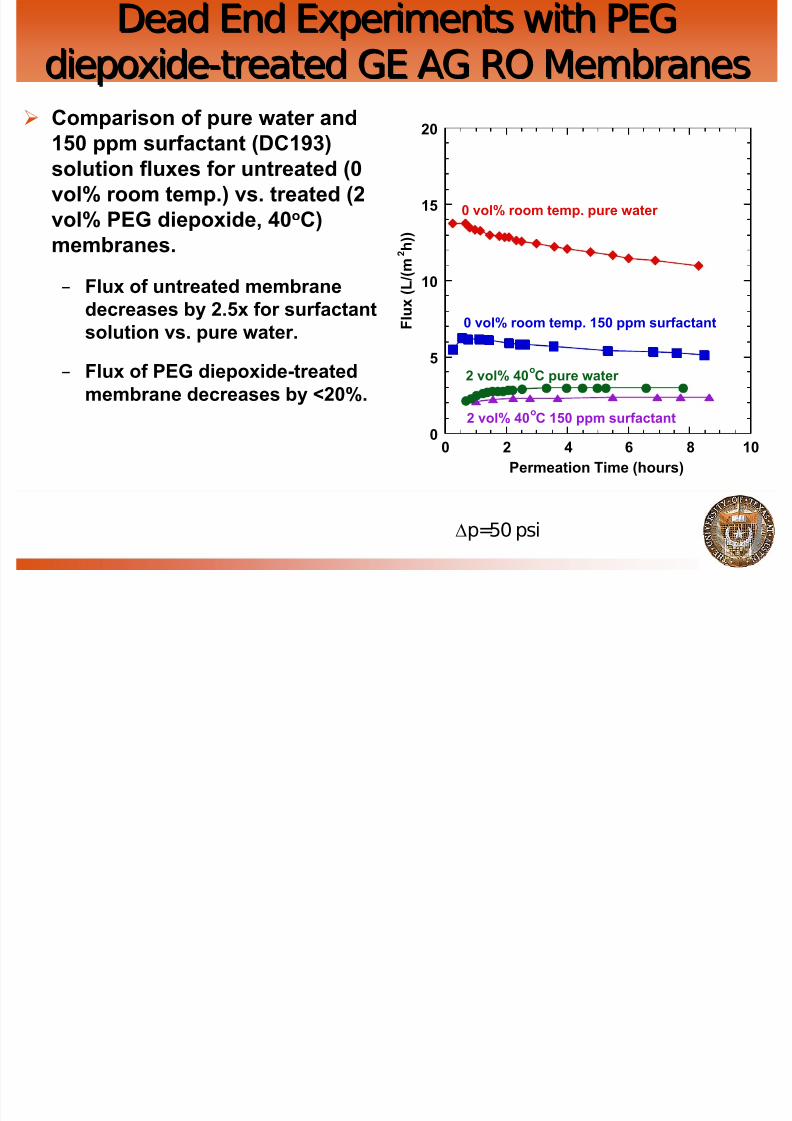
8222019 Oilfield Wh
httpslidepdfcomreaderfulloilfield-wh 4364
Treatment and Re-Injection
Two major efforts at UTTwo major efforts at UT
frac34frac34 Water ReWater Re--Injection ResearchInjection Research
frac34frac34 Industry fundedIndustry funded
frac34frac34 FoulingFouling--Resistant Membranes for Resistant Membranes for
Produced Water PurificationProduced Water Purification
frac34frac34 DOE and industry fundedDOE and industry funded
Oilfield Water Handling
8222019 Oilfield Wh
httpslidepdfcomreaderfulloilfield-wh 4464
Treatment and Re-Injection
QuestionsQuestions
CommentsComments
Contact Angle vs Water Uptake in SeveralContact Angle vs Water Uptake in SeveralFamilies of MaterialsFamilies of Materials
8222019 Oilfield Wh
httpslidepdfcomreaderfulloilfield-wh 4564
Families of MaterialsFamilies of Materials
All chemistries show a similar trend
35
40
45
50
55
60
65
0 50 100 150 200 250 300 350 400
W a t e r C
o n t a c t A n g l e ( 0 )
Water Uptake (wt)
PEGDA n=13
PEGDA n=10
5050 PEGDAPEGA
Coating ApparatusCoating Apparatus
8222019 Oilfield Wh
httpslidepdfcomreaderfulloilfield-wh 4664
PVDF support membrane
Drawdown rod
Coating speed
Coating ProcedureCoating Procedure
8222019 Oilfield Wh
httpslidepdfcomreaderfulloilfield-wh 4764
frac34Variables rod size (coating thickness) andcoating speed
frac34Select the ideal rod size (6microm-100microm)frac34Mount the support membrane samples on the
glass surface and lower the weight armassembly
frac34Spread the prepolymerization mixture near the
rod and coat the support
Characterization of Coated RO MembraneCharacterization of Coated RO Membrane
8222019 Oilfield Wh
httpslidepdfcomreaderfulloilfield-wh 4864
WaterContactAngleCoated 527plusmn21
Uncoated 670plusmn10
frac34 Substrate AG membrane
frac34 Applied PEGDA in 60 wt water with 2 wt high MW PEO
frac34 PEGDA solution thickness ~ 50microns
2
3
4
5
6
7
8
0 50 100 150 200 250 300 350 400
W a t e r F l u x a t 5 0 p s i g
( L m 2 h r )
Permeation Time (min)
Coated Sample
Uncoated Sample
Pre-filtered water 50 psig
(L p = 22 Lm2 hr bar)Angle measured using decane
Literature Data PEG diepoxideLiterature Data PEG diepoxide--treated RO Membranestreated RO Membranes
8222019 Oilfield Wh
httpslidepdfcomreaderfulloilfield-wh 4964
Sample Flux with
SurfactantA
Flux
after 2 hr Rinse
Flux with
SurfactantB
Flux after
2 hr rinsewith testsolution
Untreated 78 85 69 84Treated (03
PEGdiepoxide
(mwasymp200)50oC)
89 94 80 100
frac34 Test solution (1500 ppmNaCl ∆p = 150 psi) used for baseline flux all percentagesare compared to this flux
frac34 Surfactant solutions contain 1500 ppmNaCl andndash Surfactant A 100 mM dodecyltrimethyl ammonium bromide
ndash Surfactant B 100 ppmsodium dodecyl sulfate
frac34 First rinse is purified water flux is of 2000 ppmNaCl solution
frac34
Flux measured after 3 hrs of treatment unless stated otherwiseMickols William E US Patent 6280853 B1 2001
Test condition ∆p = 150 psi
SurfactantsSurfactants
8222019 Oilfield Wh
httpslidepdfcomreaderfulloilfield-wh 5064
frac34Dodecyltrimethyl ammonium bromide
frac34Sodium dodecyl sulfate
N+
CH3
CH3
H3C
Br -
O
S
O
OHO
Dead End Experiments with PEGDead End Experiments with PEGdiepoxidediepoxide--treated GE AG RO Membranestreated GE AG RO Membranes
8222019 Oilfield Wh
httpslidepdfcomreaderfulloilfield-wh 5164
diepoxidediepoxide treated GE AG RO Membranestreated GE AG RO Membranes
frac34 Stirred cell 50 psi
frac34 Pure water flux
frac34 PEG diepoxide-treatedmembranes (2 and 4 vol at40oC) have 4-5 times lower flux
than untreated membrane (0vol at room temp)
0
2
4
6
8
10
12
14
0 2 4 6 8 10
F l u
x ( L ( m 2 h ) )
Permeation Time (hours)
0 vol room temp
0 vol 40oC
2 vol 40oC
4 vol 40oC
FTIRFTIR--ATR of PEG diepoxideATR of PEG diepoxide--treated ROtreated ROMembraneMembrane
8222019 Oilfield Wh
httpslidepdfcomreaderfulloilfield-wh 5264
frac34 Spectrum 0 PEG diepoxidesolution spectrum minus 4 PEGdiepoxide solution spectrum (bothat 40oC)
ndash Increases at 2950 cm-1and 1100cm-1 indicate an increase inalkane and aliphatic ether content respectively due topresence of PEG diepoxide onthe membrane surface
ndash Decreases in the range from1400-1800 cm-1 indicatedecrease in either free aminesor carboxylic acid groups (bothgroups absorb in this region) -0015
-001
-0005
0
0005
001
0015
500100015002000250030003500
A b
s o r b a n c e
Wavenumber (cm-1
)
Chemical Attachment of PEGChemical Attachment of PEGC ti t RO S fC ti t RO S f
8222019 Oilfield Wh
httpslidepdfcomreaderfulloilfield-wh 5364
Coatings to RO SurfacesCoatings to RO Surfaces
frac34Using coating machine to control filmthickness spread pre-polymerization
mixture on membrane surface then UVpolymerize to form hydrophilic surfacelayerndash Possible membranes
bull Original commercial RO membrane
bull Membrane with grafted methacryloyl chloridemolecules
CH2 C
CH3
C
O
Cl
Methacryloyl chloride
Methacryloyl Chloride Reaction with TerminalMethacryloyl Chloride Reaction with TerminalAmines of RO MembranesAmines of RO Membranes
8222019 Oilfield Wh
httpslidepdfcomreaderfulloilfield-wh 5464
HN NH C
O
C
O
C O
NH NH C
O
C O
OH
C
O
n
HN NH C
O
C
O
C O
NH NH C
O
C O
OH
C
O
n
1-n
1-n
NH NH2
NH NH C
H2C C
CH3
C
O
Cl
O
C
CH3
CH2
HCl
Grafting Methacryloyl ChlorideGrafting Methacryloyl Chloride
8222019 Oilfield Wh
httpslidepdfcomreaderfulloilfield-wh 5564
frac34 FTIR subtractionspectrum of membrane in
solvent from membranesoaked in 25 wtsolution of methacryloylchloride for 20 hours
frac34 Decreases at 1650 and1100 cm-1 indicatereaction occurs probablywith free amines
-0025
-002
-0015
-001
-0005
0
0005
001
5001000150020002500300035004000
A b s o r b a n c e
Wavenumber (cm-1
)
Contact Angle ExperimentsContact Angle Experiments
8222019 Oilfield Wh
httpslidepdfcomreaderfulloilfield-wh 5664
Rameacute-Hart NRL Contact AngleGoniometer ( Model 100)
frac34 Pendant drop measurements
frac34 Environmental chamber permits testing in water at
controlled temperaturefrac34 Measure equilibrium contact angle
OilWater FoulingOilWater Fouling DecaneDecane EmulsionEmulsion
8222019 Oilfield Wh
httpslidepdfcomreaderfulloilfield-wh 5764
Sample1
Sample2
Feed(ppm)
1020 1020
Retentate(ppm)
1322 2110
Final
Permeate(ppm) 65 118
FinalRejection
995 994
1500 ppm by weight emulsion prepared with
9 parts decane to 1 part Dow Corning Fluid193 surfactant
AG RO membrane
(Lp = 28 plusmn 02 Lm2 hr bar)
dead-end filtration∆ p = 50 psig
0
2
4
6
8
10
12
0 100 200 300 400 500 600
W a t e r F l u x ( L
m 2 h r )
Permeation Time (min)
Pure Water
Decane 1
Decane 2
New Linking Chemistries to Access Libraries of New Linking Chemistries to Access Libraries of
Grafting ChemistriesGrafting Chemistries
8222019 Oilfield Wh
httpslidepdfcomreaderfulloilfield-wh 5864
Grafting Chemistriesg
CCl
O
O OH
Cl C
O
O
O
H
CCl
O
OH O
Reaction Conditions 25o
C dichloromethane (solvent)Koerner T et al Journal of Organic Chemistry 1999 64 196-201
Coulter Counter Measure of Emulsion StabilityCoulter Counter Measure of Emulsion Stability
8222019 Oilfield Wh
httpslidepdfcomreaderfulloilfield-wh 5964
1500ppm 61 180s
Contact Angle Measurements Pendant DropContact Angle Measurements Pendant Drop
8222019 Oilfield Wh
httpslidepdfcomreaderfulloilfield-wh 6064
Liquid 2 (Decane)
SampleReportedAngle
Sample Holder Syringe Needle
Liquid 1 (Water)
Background on Contact AnglesBackground on Contact AnglesConvention is to measure angle through the aqueous phase
8222019 Oilfield Wh
httpslidepdfcomreaderfulloilfield-wh 6164
Oil
Water
Water Angle lt900
Oil droplet has minimum
contact with surface ie
surface is hydrophilic
Water Angle gt900
Oil droplet has maximum
contact with surface ie
surface is hydrophobic
Convention is to measure angle through the aqueous phase
Water Angle = 1800 ndash Oil Angle
Effect of Concentration andEffect of Concentration andOilSurfactant Ratio onOilSurfactant Ratio on PolydispersityPolydispersity
8222019 Oilfield Wh
httpslidepdfcomreaderfulloilfield-wh 6264
OilSurfactant Ratio onOilSurfactant Ratio on PolydispersityPolydispersity
Blending time was fixed at 180 seconds
Coulter Counter Measure of the Effect of Coulter Counter Measure of the Effect of Concentration on Size and DistributionConcentration on Size and Distribution
8222019 Oilfield Wh
httpslidepdfcomreaderfulloilfield-wh 6364
Blending time was fixed at 180 seconds
Effect of Concentration andEffect of Concentration andOilSurfactant Ratio on SizeOilSurfactant Ratio on Size
8222019 Oilfield Wh
httpslidepdfcomreaderfulloilfield-wh 6464
Blending time was fixed at 180 seconds
8222019 Oilfield Wh
httpslidepdfcomreaderfulloilfield-wh 4464
Treatment and Re-Injection
QuestionsQuestions
CommentsComments
Contact Angle vs Water Uptake in SeveralContact Angle vs Water Uptake in SeveralFamilies of MaterialsFamilies of Materials
8222019 Oilfield Wh
httpslidepdfcomreaderfulloilfield-wh 4564
Families of MaterialsFamilies of Materials
All chemistries show a similar trend
35
40
45
50
55
60
65
0 50 100 150 200 250 300 350 400
W a t e r C
o n t a c t A n g l e ( 0 )
Water Uptake (wt)
PEGDA n=13
PEGDA n=10
5050 PEGDAPEGA
Coating ApparatusCoating Apparatus
8222019 Oilfield Wh
httpslidepdfcomreaderfulloilfield-wh 4664
PVDF support membrane
Drawdown rod
Coating speed
Coating ProcedureCoating Procedure
8222019 Oilfield Wh
httpslidepdfcomreaderfulloilfield-wh 4764
frac34Variables rod size (coating thickness) andcoating speed
frac34Select the ideal rod size (6microm-100microm)frac34Mount the support membrane samples on the
glass surface and lower the weight armassembly
frac34Spread the prepolymerization mixture near the
rod and coat the support
Characterization of Coated RO MembraneCharacterization of Coated RO Membrane
8222019 Oilfield Wh
httpslidepdfcomreaderfulloilfield-wh 4864
WaterContactAngleCoated 527plusmn21
Uncoated 670plusmn10
frac34 Substrate AG membrane
frac34 Applied PEGDA in 60 wt water with 2 wt high MW PEO
frac34 PEGDA solution thickness ~ 50microns
2
3
4
5
6
7
8
0 50 100 150 200 250 300 350 400
W a t e r F l u x a t 5 0 p s i g
( L m 2 h r )
Permeation Time (min)
Coated Sample
Uncoated Sample
Pre-filtered water 50 psig
(L p = 22 Lm2 hr bar)Angle measured using decane
Literature Data PEG diepoxideLiterature Data PEG diepoxide--treated RO Membranestreated RO Membranes
8222019 Oilfield Wh
httpslidepdfcomreaderfulloilfield-wh 4964
Sample Flux with
SurfactantA
Flux
after 2 hr Rinse
Flux with
SurfactantB
Flux after
2 hr rinsewith testsolution
Untreated 78 85 69 84Treated (03
PEGdiepoxide
(mwasymp200)50oC)
89 94 80 100
frac34 Test solution (1500 ppmNaCl ∆p = 150 psi) used for baseline flux all percentagesare compared to this flux
frac34 Surfactant solutions contain 1500 ppmNaCl andndash Surfactant A 100 mM dodecyltrimethyl ammonium bromide
ndash Surfactant B 100 ppmsodium dodecyl sulfate
frac34 First rinse is purified water flux is of 2000 ppmNaCl solution
frac34
Flux measured after 3 hrs of treatment unless stated otherwiseMickols William E US Patent 6280853 B1 2001
Test condition ∆p = 150 psi
SurfactantsSurfactants
8222019 Oilfield Wh
httpslidepdfcomreaderfulloilfield-wh 5064
frac34Dodecyltrimethyl ammonium bromide
frac34Sodium dodecyl sulfate
N+
CH3
CH3
H3C
Br -
O
S
O
OHO
Dead End Experiments with PEGDead End Experiments with PEGdiepoxidediepoxide--treated GE AG RO Membranestreated GE AG RO Membranes
8222019 Oilfield Wh
httpslidepdfcomreaderfulloilfield-wh 5164
diepoxidediepoxide treated GE AG RO Membranestreated GE AG RO Membranes
frac34 Stirred cell 50 psi
frac34 Pure water flux
frac34 PEG diepoxide-treatedmembranes (2 and 4 vol at40oC) have 4-5 times lower flux
than untreated membrane (0vol at room temp)
0
2
4
6
8
10
12
14
0 2 4 6 8 10
F l u
x ( L ( m 2 h ) )
Permeation Time (hours)
0 vol room temp
0 vol 40oC
2 vol 40oC
4 vol 40oC
FTIRFTIR--ATR of PEG diepoxideATR of PEG diepoxide--treated ROtreated ROMembraneMembrane
8222019 Oilfield Wh
httpslidepdfcomreaderfulloilfield-wh 5264
frac34 Spectrum 0 PEG diepoxidesolution spectrum minus 4 PEGdiepoxide solution spectrum (bothat 40oC)
ndash Increases at 2950 cm-1and 1100cm-1 indicate an increase inalkane and aliphatic ether content respectively due topresence of PEG diepoxide onthe membrane surface
ndash Decreases in the range from1400-1800 cm-1 indicatedecrease in either free aminesor carboxylic acid groups (bothgroups absorb in this region) -0015
-001
-0005
0
0005
001
0015
500100015002000250030003500
A b
s o r b a n c e
Wavenumber (cm-1
)
Chemical Attachment of PEGChemical Attachment of PEGC ti t RO S fC ti t RO S f
8222019 Oilfield Wh
httpslidepdfcomreaderfulloilfield-wh 5364
Coatings to RO SurfacesCoatings to RO Surfaces
frac34Using coating machine to control filmthickness spread pre-polymerization
mixture on membrane surface then UVpolymerize to form hydrophilic surfacelayerndash Possible membranes
bull Original commercial RO membrane
bull Membrane with grafted methacryloyl chloridemolecules
CH2 C
CH3
C
O
Cl
Methacryloyl chloride
Methacryloyl Chloride Reaction with TerminalMethacryloyl Chloride Reaction with TerminalAmines of RO MembranesAmines of RO Membranes
8222019 Oilfield Wh
httpslidepdfcomreaderfulloilfield-wh 5464
HN NH C
O
C
O
C O
NH NH C
O
C O
OH
C
O
n
HN NH C
O
C
O
C O
NH NH C
O
C O
OH
C
O
n
1-n
1-n
NH NH2
NH NH C
H2C C
CH3
C
O
Cl
O
C
CH3
CH2
HCl
Grafting Methacryloyl ChlorideGrafting Methacryloyl Chloride
8222019 Oilfield Wh
httpslidepdfcomreaderfulloilfield-wh 5564
frac34 FTIR subtractionspectrum of membrane in
solvent from membranesoaked in 25 wtsolution of methacryloylchloride for 20 hours
frac34 Decreases at 1650 and1100 cm-1 indicatereaction occurs probablywith free amines
-0025
-002
-0015
-001
-0005
0
0005
001
5001000150020002500300035004000
A b s o r b a n c e
Wavenumber (cm-1
)
Contact Angle ExperimentsContact Angle Experiments
8222019 Oilfield Wh
httpslidepdfcomreaderfulloilfield-wh 5664
Rameacute-Hart NRL Contact AngleGoniometer ( Model 100)
frac34 Pendant drop measurements
frac34 Environmental chamber permits testing in water at
controlled temperaturefrac34 Measure equilibrium contact angle
OilWater FoulingOilWater Fouling DecaneDecane EmulsionEmulsion
8222019 Oilfield Wh
httpslidepdfcomreaderfulloilfield-wh 5764
Sample1
Sample2
Feed(ppm)
1020 1020
Retentate(ppm)
1322 2110
Final
Permeate(ppm) 65 118
FinalRejection
995 994
1500 ppm by weight emulsion prepared with
9 parts decane to 1 part Dow Corning Fluid193 surfactant
AG RO membrane
(Lp = 28 plusmn 02 Lm2 hr bar)
dead-end filtration∆ p = 50 psig
0
2
4
6
8
10
12
0 100 200 300 400 500 600
W a t e r F l u x ( L
m 2 h r )
Permeation Time (min)
Pure Water
Decane 1
Decane 2
New Linking Chemistries to Access Libraries of New Linking Chemistries to Access Libraries of
Grafting ChemistriesGrafting Chemistries
8222019 Oilfield Wh
httpslidepdfcomreaderfulloilfield-wh 5864
Grafting Chemistriesg
CCl
O
O OH
Cl C
O
O
O
H
CCl
O
OH O
Reaction Conditions 25o
C dichloromethane (solvent)Koerner T et al Journal of Organic Chemistry 1999 64 196-201
Coulter Counter Measure of Emulsion StabilityCoulter Counter Measure of Emulsion Stability
8222019 Oilfield Wh
httpslidepdfcomreaderfulloilfield-wh 5964
1500ppm 61 180s
Contact Angle Measurements Pendant DropContact Angle Measurements Pendant Drop
8222019 Oilfield Wh
httpslidepdfcomreaderfulloilfield-wh 6064
Liquid 2 (Decane)
SampleReportedAngle
Sample Holder Syringe Needle
Liquid 1 (Water)
Background on Contact AnglesBackground on Contact AnglesConvention is to measure angle through the aqueous phase
8222019 Oilfield Wh
httpslidepdfcomreaderfulloilfield-wh 6164
Oil
Water
Water Angle lt900
Oil droplet has minimum
contact with surface ie
surface is hydrophilic
Water Angle gt900
Oil droplet has maximum
contact with surface ie
surface is hydrophobic
Convention is to measure angle through the aqueous phase
Water Angle = 1800 ndash Oil Angle
Effect of Concentration andEffect of Concentration andOilSurfactant Ratio onOilSurfactant Ratio on PolydispersityPolydispersity
8222019 Oilfield Wh
httpslidepdfcomreaderfulloilfield-wh 6264
OilSurfactant Ratio onOilSurfactant Ratio on PolydispersityPolydispersity
Blending time was fixed at 180 seconds
Coulter Counter Measure of the Effect of Coulter Counter Measure of the Effect of Concentration on Size and DistributionConcentration on Size and Distribution
8222019 Oilfield Wh
httpslidepdfcomreaderfulloilfield-wh 6364
Blending time was fixed at 180 seconds
Effect of Concentration andEffect of Concentration andOilSurfactant Ratio on SizeOilSurfactant Ratio on Size
8222019 Oilfield Wh
httpslidepdfcomreaderfulloilfield-wh 6464
Blending time was fixed at 180 seconds

8222019 Oilfield Wh
httpslidepdfcomreaderfulloilfield-wh 4764
frac34Variables rod size (coating thickness) andcoating speed
frac34Select the ideal rod size (6microm-100microm)frac34Mount the support membrane samples on the
glass surface and lower the weight armassembly
frac34Spread the prepolymerization mixture near the
rod and coat the support
Characterization of Coated RO MembraneCharacterization of Coated RO Membrane
8222019 Oilfield Wh
httpslidepdfcomreaderfulloilfield-wh 4864
WaterContactAngleCoated 527plusmn21
Uncoated 670plusmn10
frac34 Substrate AG membrane
frac34 Applied PEGDA in 60 wt water with 2 wt high MW PEO
frac34 PEGDA solution thickness ~ 50microns
2
3
4
5
6
7
8
0 50 100 150 200 250 300 350 400
W a t e r F l u x a t 5 0 p s i g
( L m 2 h r )
Permeation Time (min)
Coated Sample
Uncoated Sample
Pre-filtered water 50 psig
(L p = 22 Lm2 hr bar)Angle measured using decane
Literature Data PEG diepoxideLiterature Data PEG diepoxide--treated RO Membranestreated RO Membranes
8222019 Oilfield Wh
httpslidepdfcomreaderfulloilfield-wh 4964
Sample Flux with
SurfactantA
Flux
after 2 hr Rinse
Flux with
SurfactantB
Flux after
2 hr rinsewith testsolution
Untreated 78 85 69 84Treated (03
PEGdiepoxide
(mwasymp200)50oC)
89 94 80 100
frac34 Test solution (1500 ppmNaCl ∆p = 150 psi) used for baseline flux all percentagesare compared to this flux
frac34 Surfactant solutions contain 1500 ppmNaCl andndash Surfactant A 100 mM dodecyltrimethyl ammonium bromide
ndash Surfactant B 100 ppmsodium dodecyl sulfate
frac34 First rinse is purified water flux is of 2000 ppmNaCl solution
frac34
Flux measured after 3 hrs of treatment unless stated otherwiseMickols William E US Patent 6280853 B1 2001
Test condition ∆p = 150 psi
SurfactantsSurfactants
8222019 Oilfield Wh
httpslidepdfcomreaderfulloilfield-wh 5064
frac34Dodecyltrimethyl ammonium bromide
frac34Sodium dodecyl sulfate
N+
CH3
CH3
H3C
Br -
O
S
O
OHO
Dead End Experiments with PEGDead End Experiments with PEGdiepoxidediepoxide--treated GE AG RO Membranestreated GE AG RO Membranes
8222019 Oilfield Wh
httpslidepdfcomreaderfulloilfield-wh 5164
diepoxidediepoxide treated GE AG RO Membranestreated GE AG RO Membranes
frac34 Stirred cell 50 psi
frac34 Pure water flux
frac34 PEG diepoxide-treatedmembranes (2 and 4 vol at40oC) have 4-5 times lower flux
than untreated membrane (0vol at room temp)
0
2
4
6
8
10
12
14
0 2 4 6 8 10
F l u
x ( L ( m 2 h ) )
Permeation Time (hours)
0 vol room temp
0 vol 40oC
2 vol 40oC
4 vol 40oC
FTIRFTIR--ATR of PEG diepoxideATR of PEG diepoxide--treated ROtreated ROMembraneMembrane
8222019 Oilfield Wh
httpslidepdfcomreaderfulloilfield-wh 5264
frac34 Spectrum 0 PEG diepoxidesolution spectrum minus 4 PEGdiepoxide solution spectrum (bothat 40oC)
ndash Increases at 2950 cm-1and 1100cm-1 indicate an increase inalkane and aliphatic ether content respectively due topresence of PEG diepoxide onthe membrane surface
ndash Decreases in the range from1400-1800 cm-1 indicatedecrease in either free aminesor carboxylic acid groups (bothgroups absorb in this region) -0015
-001
-0005
0
0005
001
0015
500100015002000250030003500
A b
s o r b a n c e
Wavenumber (cm-1
)
Chemical Attachment of PEGChemical Attachment of PEGC ti t RO S fC ti t RO S f
8222019 Oilfield Wh
httpslidepdfcomreaderfulloilfield-wh 5364
Coatings to RO SurfacesCoatings to RO Surfaces
frac34Using coating machine to control filmthickness spread pre-polymerization
mixture on membrane surface then UVpolymerize to form hydrophilic surfacelayerndash Possible membranes
bull Original commercial RO membrane
bull Membrane with grafted methacryloyl chloridemolecules
CH2 C
CH3
C
O
Cl
Methacryloyl chloride
Methacryloyl Chloride Reaction with TerminalMethacryloyl Chloride Reaction with TerminalAmines of RO MembranesAmines of RO Membranes
8222019 Oilfield Wh
httpslidepdfcomreaderfulloilfield-wh 5464
HN NH C
O
C
O
C O
NH NH C
O
C O
OH
C
O
n
HN NH C
O
C
O
C O
NH NH C
O
C O
OH
C
O
n
1-n
1-n
NH NH2
NH NH C
H2C C
CH3
C
O
Cl
O
C
CH3
CH2
HCl
Grafting Methacryloyl ChlorideGrafting Methacryloyl Chloride
8222019 Oilfield Wh
httpslidepdfcomreaderfulloilfield-wh 5564
frac34 FTIR subtractionspectrum of membrane in
solvent from membranesoaked in 25 wtsolution of methacryloylchloride for 20 hours
frac34 Decreases at 1650 and1100 cm-1 indicatereaction occurs probablywith free amines
-0025
-002
-0015
-001
-0005
0
0005
001
5001000150020002500300035004000
A b s o r b a n c e
Wavenumber (cm-1
)
Contact Angle ExperimentsContact Angle Experiments
8222019 Oilfield Wh
httpslidepdfcomreaderfulloilfield-wh 5664
Rameacute-Hart NRL Contact AngleGoniometer ( Model 100)
frac34 Pendant drop measurements
frac34 Environmental chamber permits testing in water at
controlled temperaturefrac34 Measure equilibrium contact angle
OilWater FoulingOilWater Fouling DecaneDecane EmulsionEmulsion
8222019 Oilfield Wh
httpslidepdfcomreaderfulloilfield-wh 5764
Sample1
Sample2
Feed(ppm)
1020 1020
Retentate(ppm)
1322 2110
Final
Permeate(ppm) 65 118
FinalRejection
995 994
1500 ppm by weight emulsion prepared with
9 parts decane to 1 part Dow Corning Fluid193 surfactant
AG RO membrane
(Lp = 28 plusmn 02 Lm2 hr bar)
dead-end filtration∆ p = 50 psig
0
2
4
6
8
10
12
0 100 200 300 400 500 600
W a t e r F l u x ( L
m 2 h r )
Permeation Time (min)
Pure Water
Decane 1
Decane 2
New Linking Chemistries to Access Libraries of New Linking Chemistries to Access Libraries of
Grafting ChemistriesGrafting Chemistries
8222019 Oilfield Wh
httpslidepdfcomreaderfulloilfield-wh 5864
Grafting Chemistriesg
CCl
O
O OH
Cl C
O
O
O
H
CCl
O
OH O
Reaction Conditions 25o
C dichloromethane (solvent)Koerner T et al Journal of Organic Chemistry 1999 64 196-201
Coulter Counter Measure of Emulsion StabilityCoulter Counter Measure of Emulsion Stability
8222019 Oilfield Wh
httpslidepdfcomreaderfulloilfield-wh 5964
1500ppm 61 180s
Contact Angle Measurements Pendant DropContact Angle Measurements Pendant Drop
8222019 Oilfield Wh
httpslidepdfcomreaderfulloilfield-wh 6064
Liquid 2 (Decane)
SampleReportedAngle
Sample Holder Syringe Needle
Liquid 1 (Water)
Background on Contact AnglesBackground on Contact AnglesConvention is to measure angle through the aqueous phase
8222019 Oilfield Wh
httpslidepdfcomreaderfulloilfield-wh 6164
Oil
Water
Water Angle lt900
Oil droplet has minimum
contact with surface ie
surface is hydrophilic
Water Angle gt900
Oil droplet has maximum
contact with surface ie
surface is hydrophobic
Convention is to measure angle through the aqueous phase
Water Angle = 1800 ndash Oil Angle
Effect of Concentration andEffect of Concentration andOilSurfactant Ratio onOilSurfactant Ratio on PolydispersityPolydispersity
8222019 Oilfield Wh
httpslidepdfcomreaderfulloilfield-wh 6264
OilSurfactant Ratio onOilSurfactant Ratio on PolydispersityPolydispersity
Blending time was fixed at 180 seconds
Coulter Counter Measure of the Effect of Coulter Counter Measure of the Effect of Concentration on Size and DistributionConcentration on Size and Distribution
8222019 Oilfield Wh
httpslidepdfcomreaderfulloilfield-wh 6364
Blending time was fixed at 180 seconds
Effect of Concentration andEffect of Concentration andOilSurfactant Ratio on SizeOilSurfactant Ratio on Size
8222019 Oilfield Wh
httpslidepdfcomreaderfulloilfield-wh 6464
Blending time was fixed at 180 seconds
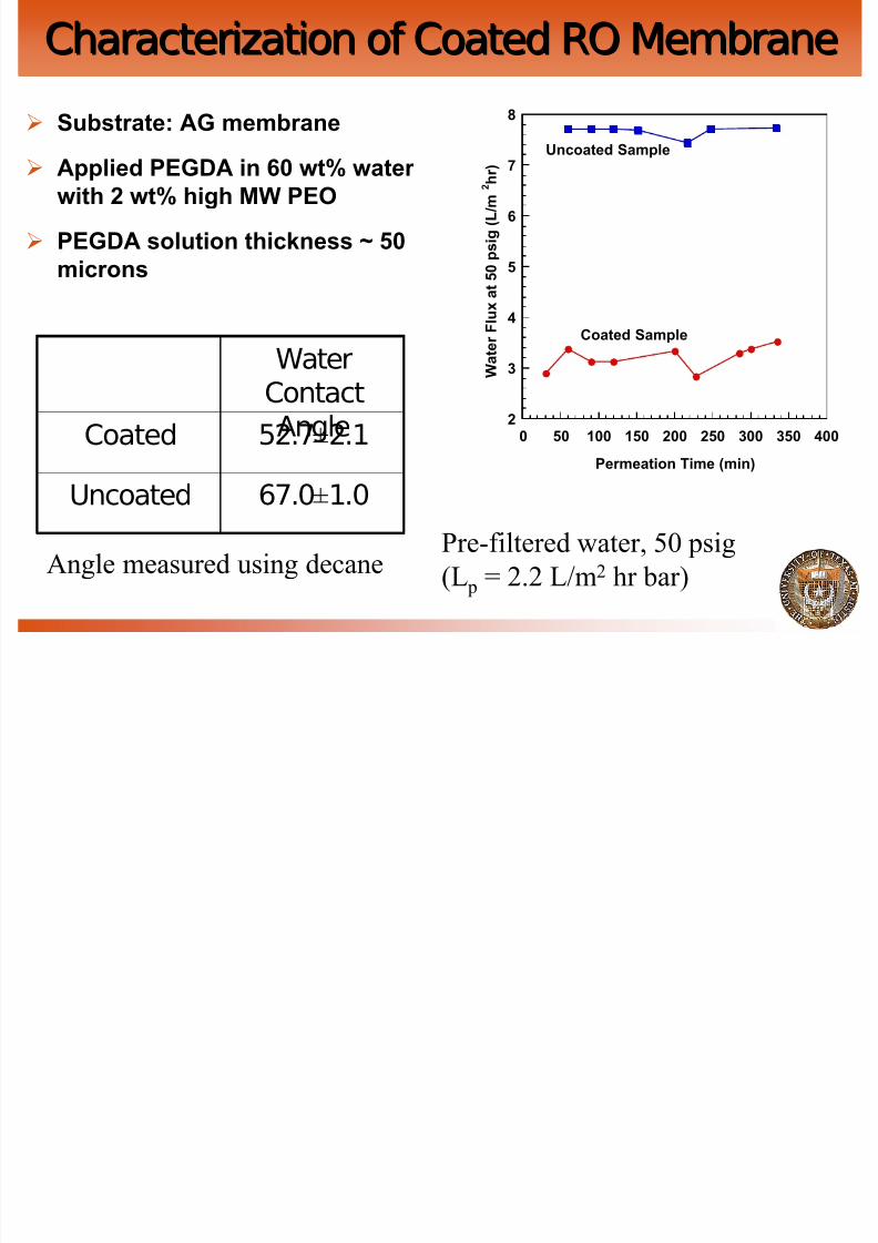
8222019 Oilfield Wh
httpslidepdfcomreaderfulloilfield-wh 5164
diepoxidediepoxide treated GE AG RO Membranestreated GE AG RO Membranes
frac34 Stirred cell 50 psi
frac34 Pure water flux
frac34 PEG diepoxide-treatedmembranes (2 and 4 vol at40oC) have 4-5 times lower flux
than untreated membrane (0vol at room temp)
0
2
4
6
8
10
12
14
0 2 4 6 8 10
F l u
x ( L ( m 2 h ) )
Permeation Time (hours)
0 vol room temp
0 vol 40oC
2 vol 40oC
4 vol 40oC
FTIRFTIR--ATR of PEG diepoxideATR of PEG diepoxide--treated ROtreated ROMembraneMembrane
8222019 Oilfield Wh
httpslidepdfcomreaderfulloilfield-wh 5264
frac34 Spectrum 0 PEG diepoxidesolution spectrum minus 4 PEGdiepoxide solution spectrum (bothat 40oC)
ndash Increases at 2950 cm-1and 1100cm-1 indicate an increase inalkane and aliphatic ether content respectively due topresence of PEG diepoxide onthe membrane surface
ndash Decreases in the range from1400-1800 cm-1 indicatedecrease in either free aminesor carboxylic acid groups (bothgroups absorb in this region) -0015
-001
-0005
0
0005
001
0015
500100015002000250030003500
A b
s o r b a n c e
Wavenumber (cm-1
)
Chemical Attachment of PEGChemical Attachment of PEGC ti t RO S fC ti t RO S f
8222019 Oilfield Wh
httpslidepdfcomreaderfulloilfield-wh 5364
Coatings to RO SurfacesCoatings to RO Surfaces
frac34Using coating machine to control filmthickness spread pre-polymerization
mixture on membrane surface then UVpolymerize to form hydrophilic surfacelayerndash Possible membranes
bull Original commercial RO membrane
bull Membrane with grafted methacryloyl chloridemolecules
CH2 C
CH3
C
O
Cl
Methacryloyl chloride
Methacryloyl Chloride Reaction with TerminalMethacryloyl Chloride Reaction with TerminalAmines of RO MembranesAmines of RO Membranes
8222019 Oilfield Wh
httpslidepdfcomreaderfulloilfield-wh 5464
HN NH C
O
C
O
C O
NH NH C
O
C O
OH
C
O
n
HN NH C
O
C
O
C O
NH NH C
O
C O
OH
C
O
n
1-n
1-n
NH NH2
NH NH C
H2C C
CH3
C
O
Cl
O
C
CH3
CH2
HCl
Grafting Methacryloyl ChlorideGrafting Methacryloyl Chloride
8222019 Oilfield Wh
httpslidepdfcomreaderfulloilfield-wh 5564
frac34 FTIR subtractionspectrum of membrane in
solvent from membranesoaked in 25 wtsolution of methacryloylchloride for 20 hours
frac34 Decreases at 1650 and1100 cm-1 indicatereaction occurs probablywith free amines
-0025
-002
-0015
-001
-0005
0
0005
001
5001000150020002500300035004000
A b s o r b a n c e
Wavenumber (cm-1
)
Contact Angle ExperimentsContact Angle Experiments
8222019 Oilfield Wh
httpslidepdfcomreaderfulloilfield-wh 5664
Rameacute-Hart NRL Contact AngleGoniometer ( Model 100)
frac34 Pendant drop measurements
frac34 Environmental chamber permits testing in water at
controlled temperaturefrac34 Measure equilibrium contact angle
OilWater FoulingOilWater Fouling DecaneDecane EmulsionEmulsion
8222019 Oilfield Wh
httpslidepdfcomreaderfulloilfield-wh 5764
Sample1
Sample2
Feed(ppm)
1020 1020
Retentate(ppm)
1322 2110
Final
Permeate(ppm) 65 118
FinalRejection
995 994
1500 ppm by weight emulsion prepared with
9 parts decane to 1 part Dow Corning Fluid193 surfactant
AG RO membrane
(Lp = 28 plusmn 02 Lm2 hr bar)
dead-end filtration∆ p = 50 psig
0
2
4
6
8
10
12
0 100 200 300 400 500 600
W a t e r F l u x ( L
m 2 h r )
Permeation Time (min)
Pure Water
Decane 1
Decane 2
New Linking Chemistries to Access Libraries of New Linking Chemistries to Access Libraries of
Grafting ChemistriesGrafting Chemistries
8222019 Oilfield Wh
httpslidepdfcomreaderfulloilfield-wh 5864
Grafting Chemistriesg
CCl
O
O OH
Cl C
O
O
O
H
CCl
O
OH O
Reaction Conditions 25o
C dichloromethane (solvent)Koerner T et al Journal of Organic Chemistry 1999 64 196-201
Coulter Counter Measure of Emulsion StabilityCoulter Counter Measure of Emulsion Stability
8222019 Oilfield Wh
httpslidepdfcomreaderfulloilfield-wh 5964
1500ppm 61 180s
Contact Angle Measurements Pendant DropContact Angle Measurements Pendant Drop
8222019 Oilfield Wh
httpslidepdfcomreaderfulloilfield-wh 6064
Liquid 2 (Decane)
SampleReportedAngle
Sample Holder Syringe Needle
Liquid 1 (Water)
Background on Contact AnglesBackground on Contact AnglesConvention is to measure angle through the aqueous phase
8222019 Oilfield Wh
httpslidepdfcomreaderfulloilfield-wh 6164
Oil
Water
Water Angle lt900
Oil droplet has minimum
contact with surface ie
surface is hydrophilic
Water Angle gt900
Oil droplet has maximum
contact with surface ie
surface is hydrophobic
Convention is to measure angle through the aqueous phase
Water Angle = 1800 ndash Oil Angle
Effect of Concentration andEffect of Concentration andOilSurfactant Ratio onOilSurfactant Ratio on PolydispersityPolydispersity
8222019 Oilfield Wh
httpslidepdfcomreaderfulloilfield-wh 6264
OilSurfactant Ratio onOilSurfactant Ratio on PolydispersityPolydispersity
Blending time was fixed at 180 seconds
Coulter Counter Measure of the Effect of Coulter Counter Measure of the Effect of Concentration on Size and DistributionConcentration on Size and Distribution
8222019 Oilfield Wh
httpslidepdfcomreaderfulloilfield-wh 6364
Blending time was fixed at 180 seconds
Effect of Concentration andEffect of Concentration andOilSurfactant Ratio on SizeOilSurfactant Ratio on Size
8222019 Oilfield Wh
httpslidepdfcomreaderfulloilfield-wh 6464
Blending time was fixed at 180 seconds
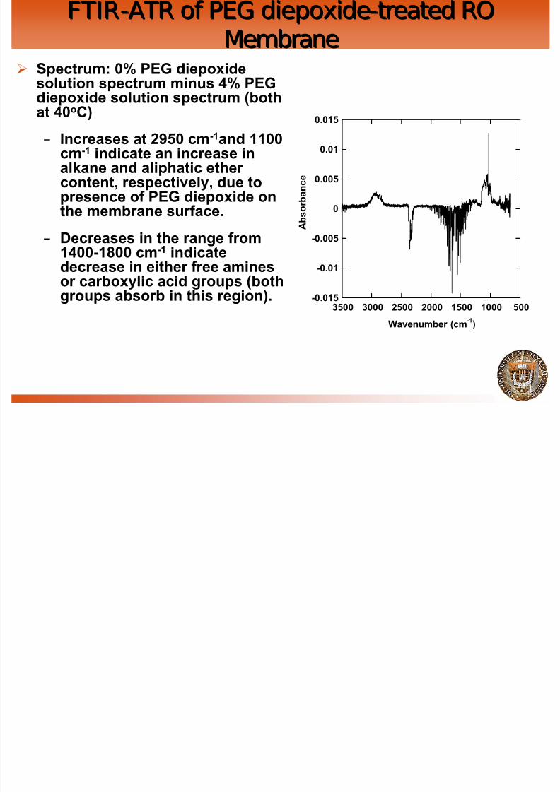
8222019 Oilfield Wh
httpslidepdfcomreaderfulloilfield-wh 5964
1500ppm 61 180s
Contact Angle Measurements Pendant DropContact Angle Measurements Pendant Drop
8222019 Oilfield Wh
httpslidepdfcomreaderfulloilfield-wh 6064
Liquid 2 (Decane)
SampleReportedAngle
Sample Holder Syringe Needle
Liquid 1 (Water)
Background on Contact AnglesBackground on Contact AnglesConvention is to measure angle through the aqueous phase
8222019 Oilfield Wh
httpslidepdfcomreaderfulloilfield-wh 6164
Oil
Water
Water Angle lt900
Oil droplet has minimum
contact with surface ie
surface is hydrophilic
Water Angle gt900
Oil droplet has maximum
contact with surface ie
surface is hydrophobic
Convention is to measure angle through the aqueous phase
Water Angle = 1800 ndash Oil Angle
Effect of Concentration andEffect of Concentration andOilSurfactant Ratio onOilSurfactant Ratio on PolydispersityPolydispersity
8222019 Oilfield Wh
httpslidepdfcomreaderfulloilfield-wh 6264
OilSurfactant Ratio onOilSurfactant Ratio on PolydispersityPolydispersity
Blending time was fixed at 180 seconds
Coulter Counter Measure of the Effect of Coulter Counter Measure of the Effect of Concentration on Size and DistributionConcentration on Size and Distribution
8222019 Oilfield Wh
httpslidepdfcomreaderfulloilfield-wh 6364
Blending time was fixed at 180 seconds
Effect of Concentration andEffect of Concentration andOilSurfactant Ratio on SizeOilSurfactant Ratio on Size
8222019 Oilfield Wh
httpslidepdfcomreaderfulloilfield-wh 6464
Blending time was fixed at 180 seconds
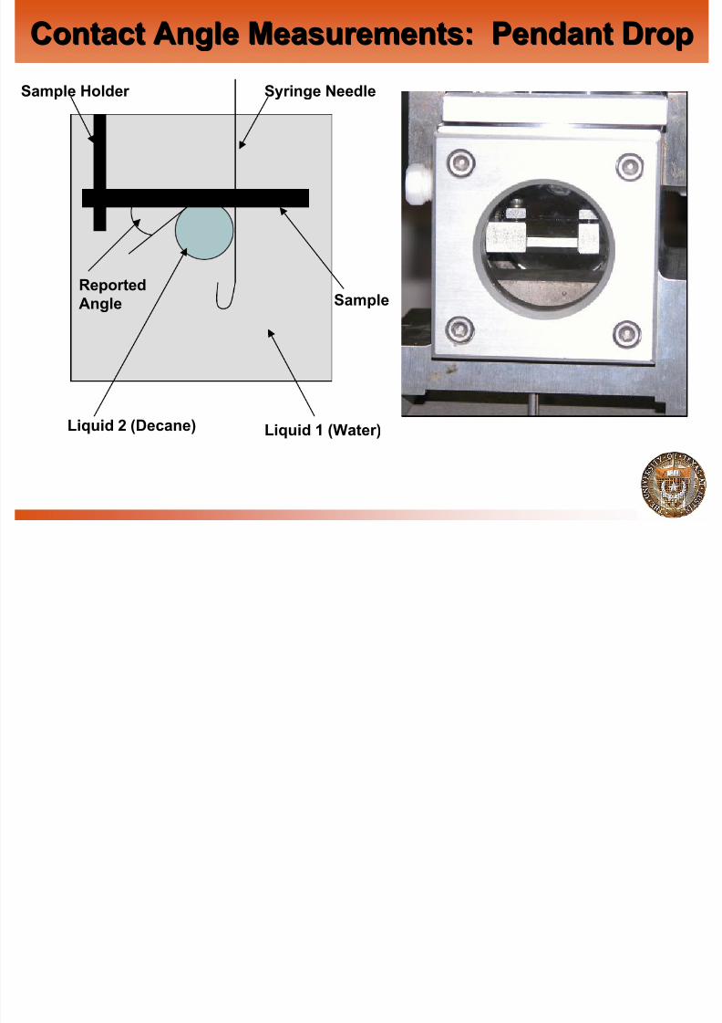
8222019 Oilfield Wh
httpslidepdfcomreaderfulloilfield-wh 6464
Blending time was fixed at 180 seconds