Oil Spill Containment, Remote Sensing and Tracking For ... · Tracking For Deepwater ... 3.0...
121
Oil Spill Containment, Remote Sensing and Tracking For Deepwater Blowouts: Status of Existing and Emerging Technologies Final Report 300 North Lee Street, Suite 201 Alexandria, Virginia 22314 USA 12 August 1999 The project described in this report was funded by the U.S. Minerals Management Service through Purchase Order Number 1435-01-98-PO-15135 This report has been reviewed by the U.S. Minerals Management Service staff for technical adequacy according to contractual specifications. The opinions, conclusions, and recommendations contained in this report are those of the authors and do not necessarily reflect the views and policies of the U.S. Minerals Management Service. The mention of a trade name or any commercial product in this report does not constitute an endorsement or recommendation for use by the U.S. Minerals Management Service. Finally, this report does not contain any commercially sensitive or proprietary data release restrictions and may be freely copied and widely distributed.
Transcript of Oil Spill Containment, Remote Sensing and Tracking For ... · Tracking For Deepwater ... 3.0...
Oil Spill Containment, Remote Sensing andTracking For Deepwater Blowouts:
Status of Existing and Emerging Technologies
Final Report
300 North Lee Street, Suite 201Alexandria, Virginia 22314 USA
12 August 1999
The project described in this report was funded by the U.S. Minerals Management Service through Purchase Order Number 1435-01-98-PO-15135
This report has been reviewed by the U.S. Minerals Management Service staff for technical adequacy according tocontractual specifications. The opinions, conclusions, and recommendations contained in this report are those of theauthors and do not necessarily reflect the views and policies of the U.S. Minerals Management Service. Themention of a trade name or any commercial product in this report does not constitute an endorsement orrecommendation for use by the U.S. Minerals Management Service. Finally, this report does not contain anycommercially sensitive or proprietary data release restrictions and may be freely copied and widely distributed.

i
TABLE OF CONTENTS
Section Title Page No.
Figures .....................................................................................................................iiiTables .....................................................................................................................ivExecutive Summary.............................................................................................................v
1.0 Introduction..............................................................................................................1
2.0 Approach..................................................................................................................3
3.0 Deepwater Well Control Barriers.............................................................................63.1 Barrier Types................................................................................................63.2 Subsea Drilling Equipment (Deepwater) .....................................................6
3.2.1 Subsea Wellhead Assemblies...........................................................73.2.2 BOP Stack ........................................................................................73.2.3 BOP Connectors (Lower & Upper)..................................................73.2.4 Choke and Kill Lines......................................................................113.2.5 Riser/Slip Joint ...............................................................................12
3.3 Subsea Completion Equipment ..................................................................14
4.0 Blowout Scenarios..................................................................................................164.1 Drilling, Completion & Workover Blowout Scenarios..............................164.2 Producing Well Scenarios ..........................................................................22
5.0 Critical Component Analysis .................................................................................245.1 Drilling, Completion & Workover Operations ..........................................245.2 Producing Wells .........................................................................................24
6.0 Consequence Analysis............................................................................................256.1 Drilling, Completion & Workover Operations ..........................................256.2 Producing Wells .........................................................................................25
7.0 Technical Hurdles to Deepwater Oil Spill Response.............................................267.1 Subsea Oil Containment.............................................................................26
7.1.1 Deepwater Currents...........................................................................267.1.2 Manipulation of Heavy Objects ........................................................267.1.3 Subsea Collectors ..............................................................................267.1.4 Installation and Approach.................................................................297.1.5 Lack of Standardization....................................................................30
7.2 Subsea Dispersant Injection.......................................................................317.3 Oil Remote Sensing and Tracking..............................................................31
7.3.1 Understanding of Plume Dynamics...................................................31

ii
7.3.2 Oil Properties.....................................................................................317.3.3 Detection...........................................................................................317.3.4 Surface Oil Surveillance and Monitoring..........................................31
7.4 Recovery of Oil on the Sea Surface ...........................................................327.5 Problem Summary......................................................................................33
8.0 Blowout Patent Search Results ..............................................................................348.1 U.S. Patents................................................................................................348.2 European Patents........................................................................................36
9.0 Potential Deepwater Blowout Countermeasures....................................................399.1 Subsea Oil Containment.............................................................................39
9.1.1 Deepwater Currents...........................................................................399.1.2 Manipulation of Heavy Objects ........................................................419.1.3 Subsea Collectors ..............................................................................429.1.4 Installation and Approach.................................................................469.1.5 Standardization..................................................................................46
9.2 Subsea Dispersant Injection.......................................................................479.3 Oil Remote Sensing and Tracking ............................................................51
9.3.1 Understanding of Plume Dynamics...................................................519.3.2 Oil Properties.....................................................................................539.3.3 Detection...........................................................................................539.3.4 Surface Oil Surveillance and Monitoring..........................................54
9.4 Recovery of Oil on the Sea Surface ...........................................................54
10.0 Conclusions and Recommendations.......................................................................5610.1 Conclusions ................................................................................................5610.2 Recommendations ......................................................................................57
References ....................................................................................................................59Glossary ....................................................................................................................62
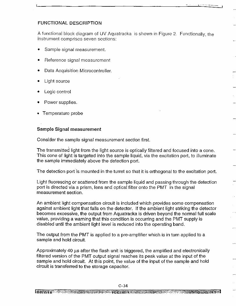
Appendix A Data Sheets for ALACE and APEX Floats............................................. A-1Appendix B The Multipurpose Deepwater Crawler (MDC 2000) ...............................B-1Appendix C Product Bulletins from Chelsea Instruments Ltd. ................................... C-1Appendix D Australian Geological Survey Organization (AGSO)
Sniffer System Description.................................................................. D-1

iii
FIGURES
Figure No. Title Page No.
1 Shallow Water Blowout Plume....................................................................32 Deteriorating Plume as Might be Expected in Deepwater ...........................53 Typical Deepwater Drilling System ............................................................84 Subsea Wellhead Assembly .........................................................................95 Subsea 18 ¾” BOP.....................................................................................106 Vetco H-4 Wellhead Connector .................................................................107 Choke & Kill Hoses in Moonpool..............................................................128 Riser Couplings ..........................................................................................129 Slip Joint.....................................................................................................1310 Typical Subsea Production Tree ................................................................1411 Wellbore Bridging......................................................................................1612 Blowout and Fire from Failed Choke Line ................................................1813 Riser Dump Valve......................................................................................1814 Drill Pipe Blowout .....................................................................................1915 Seal Port Failure.........................................................................................2016 Surface Boil Due to Well Broaching..........................................................2117 The IXTOC 1 “Sombrero” Collector.........................................................2718 Subsurface Cone.........................................................................................2819 Schematic of Bell Shaped, Rigid Wall and Flexible Sided Columns ........3020 Arrangement of the Two Acoustic Doppler Profilers on the
Support Vessel.........................................................................................4021 ROV Interface Panel and Hot Stab ............................................................4322 Single Point Docking Unit .........................................................................4723 Concept for Subsea Dispersant Injection At The Wellhead.......................4824 Concept for Subsea Dispersant Injection In The Casing............................4925 Concept For Wellhead Independent Subsea Dispersant Application ........5026 Representative High Resolution Satellite Imagery....................................55
iv
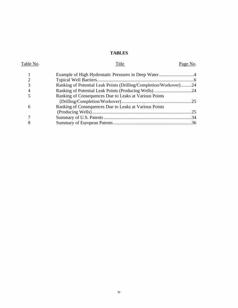
TABLES
Table No. Title Page No.
1 Example of High Hydrostatic Pressures in Deep Water..............................42 Typical Well Barriers...................................................................................63 Ranking of Potential Leak Points (Drilling/Completion/Workover) .........244 Ranking of Potential Leak Points (Producing Wells) ................................245 Ranking of Consequences Due to Leaks at Various Points
(Drilling/Completion/Workover)............................................................256 Ranking of Consequences Due to Leaks at Various Points
(Producing Wells) .....................................................................................257 Summary of U.S. Patents ...........................................................................348 Summary of European Patents ...................................................................36

v
Executive Summary
This report evaluates the technical hurdles associated with the remote sensing, tracking,containing and recovering oil released from deep water blowouts. An analysis of oil-spillcontainment and recovery technologies that will facilitate overcoming these technical hurdles isprovided.
The report presents an overview of deepwater well control barriers that are used to developdeepwater blowout scenarios. A critical component analysis and consequence analysis followthese scenarios. A patent search of deepwater blowout control technologies was performed andthe resulting patents evaluated to assist in the evaluation of potential deepwater blowoutcountermeasures. Although seven patents are identified that warrant further investigation, thereport concludes that undersea recovery of oil from a deepwater blowout is unlikely for subseareleases. The best options for subsea blowout spill control seem to be technologies to facilitatevertical intervention to contain the flow using well control techniques, and technologies forspeeding the process of natural degradation of the released oil using dispersants applied at thewellhead.
A Multi-Purpose Deepwater Crawler concept has been developed and is presented to overcomemost of the identified technical hurdles. It would have the ability to approach the blowing welland characterize the flow, assist with the manipulation of heavy objects at or near the wellhead,manipulate BOP system overrides, and apply dispersants at the blowout source.
Additional technologies for potential subsea application to deepwater blowouts include the useof enhanced CCD cameras for blowout imaging, acoustic and autonomous buoy systems forplume tracking, and towed plume detection systems.
Once the oil has reached the sea surface, existing spill response equipment and methodologiescan be used to contain and recover the oil. Since deepwater sites are typically remote from land,the use of spacecraft based imaging systems for spilled oil surveillance has the potential toovercome the fuel capacity limitations of fixed wing aircraft and helicopters.
Priority research areas for funding by MMS should include:• Development of methods to model and predict plume dynamics, including the collection of
data to validate the models• Participation in deepwater blowout simulation tests to allow the testing, evaluation and
continued development of technologies for blowout imaging, subsurface plume detection,and methods for the application of dispersants at the blowout source.
• Development of the Multi-Purpose Deepwater Crawler concept for intervention near theseafloor

1
1.0 Introduction
This study, authorized by Minerals Management Service Contract No. 1435-01-98-PO-15135,summarizes the status of existing and emerging technologies for oil spill containment, remotesensing and tracking for oil released from deepwater blowouts.
This report examines the problem of oil released from well blowouts in deep water and providesa review of past solutions and existing technologies. It identifies those technologies that have thepotential to provide rapid mobilization and deployment for deepwater blowout containment andcountermeasures. It does not address deepwater well control.
With new royalty relief, deepwater drilling and production operations have increaseddramatically. As the industry advances into deepwater exploration, the risks of blow outincrease, due to difficulties related to kick detection and control procedures under deepwaterconditions. There is very little blowout experience in deepwater from which to draw whenevaluating countermeasures.
Some research and design work occurred in the early 1980s after the 1977 oil and natural gasblowout on the Phillips Petroleum Co. ΑBravo≅ production platform in Norway and the 1979Ixtoc I blowout in the Gulf of Mexico. The Ixtoc I, the largest known blowout event, occurred in160 ft water depth. The “Sombrero” oil collector system was designed, built and installed byBrown and Root, Inc. for Pemex in an attempt to contain the oil flow from this blowout whilerelief wells were being drilled to kill the blowout. There was no advance design or planning forthis system which was designed, built and installed in less than three months. The “Sombrero”generally was considered a failure as it recovered a very low percentage of the oil released, andwas later removed after it suffered a structural failure.
The last patent for an offshore blowout recovery system was issued in 1984. In spite of numeroustheoretical and model tests studies following the Ixtoc I blowout, no method had been identifiedas a satisfactory solution (B&R, 1985). This might have been due to the concentration onsolutions requiring a high capital outlay for a low probability event; and because blowoutscenarios vary, there is not a single subsurface collection device applicable to all scenarios.
For this reason we assembled a team of experts in blowout control, deep water intervention, andoil spill countermeasures to evaluate and develop innovative technologies that will facilitate thecontainment and recovery of oil spilled from deep water blowouts. This team included PCCI,which has one of the largest group of full time marine oil spill engineering professionalssupporting industry and government; NOREN, deep water oil recovery equipment experts; andWild Well Control, Inc. which specializes in blowout control.
A draft report addressing deepwater blowout well control was prepared by the InternationalAssociation of Drilling Contractors (IADC, 1998) in conjunction with the Offshore OperatorsCommittee. This draft was reviewed prior to initiating our work and we have used the samedefinitions for water depths relative to well control, i.e.:
• Conventional 1,000 - 3,000 ft.

2
• Deepwater 3,000 - 6,500 ft.
• Ultra Deepwater 6,500 - 10,000 ft.
The emergency response section of the IADC report focused on blowout contingency planning,vertical intervention, relief wells, dynamic kill considerations, and spill control.

3
2.0 Approach
The behavior of fluids released in deep water, under high hydrostatic pressure and low ambienttemperature, are likely to be fundamentally different than for shallow water. A shallow waterrelease of oil and gas from a high pressure formation, and with a high velocity, results inturbulent mixing of the gas, oil, and water, with the mixture quickly transported to the surface bythe expanding gas under ever decreasing hydrostatic pressure (See Figure 1).
Figure 1 - Shallow Water Blowout Plume
The ocean water at many deepwater sites is greatly stratified with varying salinity, temperature,and currents. There is little historic data for deepwater well blowouts; therefore, considerabletheoretical research on the behavior of deepwater releases has been undertaken and is

4
summarized in an unpublished paper by Alan, et. al., 1997. The research raised importantquestions including:
• There has been speculation that solid methane/water hydrates might form from some blowoutgases. The formation of neutrally buoyant hydrates might eliminate the driving buoyancy ofthe rising plume. Questions remain: Under what conditions are solid hydrates formed? If thisoccurs, what becomes of the oil?
• Even without hydrate formation, oil entrained in sea water from a blowout may reach a“terminal” layer in a stratified fluid (temperature and salinity differences) at which point theplume becomes neutrally buoyant and ceases to rise. (Rye & Branvick, 1997) However, theoil may finally arrive at the sea surface due to the considerably smaller buoyancy caused bythe gas hydrates and oil driving the rise of the oil-gas-water plume. Figure 1 illustrates therelationship between depth, ambient temperature and hydrate formation from a modelsimulation of a blowout at 1200 m depth. (Reed et.al., 1999).
• The potential exists for phase separation or segregation as shown in Figure 2. One of thetheories for ultra deepwater is that the oil plume will deteriorate. This can be expectedbecause the gas and oil mixture exiting from a blowout is assumed to flow as alternatingslugs of gas and oil in a process that disperses the oil into fine droplets (Topham, 1975).These oil droplets will quickly disperse and be displaced from the gas plume in the presenceof unfavorable salinity and temperature gradients and strong horizontal currents which maybe common at deepwater depths. This may result in dispersion of oil away from the plumewith only a small gas boil reaching the surface (Westergaard, 1987).
The high hydrostatic pressures at depth (See Table 1) will aid in choking any flow from potentialblowout points. This seawater head acts as a constant backpressure which may provide bothbenefits and drawbacks for the control of oil from blowouts. Benefits include the assistance inreducing the flow that the backpressure would provide. This backpressure will slow the flowrate, and in some cases exceed the reservoir pressure in ultra deepwaters. In these casesblowouts are likely to only occur below the seafloor, with no resulting oil release to the ocean.However, by limiting the production rate, the backpressure may inhibit collapse of the well (NealAdams Firefighters, Inc. 1991).
Depth (ft) Pressure (psi)1,000 4603,000 1,3516,500 2,91010,000 4,469
Table 1 - Example of High Hydrostatic Pressures in Deep Water
Our work was performed in successive steps with due consideration of the uncertaintiesdescribed above. Section 3.0 describes barrier mechanisms and subsea drilling equipmentdesigned for well control. Wild Well Control then used first hand experience to develop blowoutscenarios for the drilling, completion and workover phases of subsea oil production, and forproducing wells, in Section 4.0. Section 5.0 provides a matrix of potential blowout exit pointsdescribing the relative likelihood of each exit point being the most probable failure point.Section 6.0 gives a ranking of the consequences of blowouts from each of the probable exit

5
points. With the information developed, Section 7.0 describes the technical hurdles anticipatedin sensing, tracking, containing, and recovering oil released from a deepwater blowout. A patentsearch was then performed in both Norway and in the U.S. for blowout containment devices.Over sixty patents applicable to blowout containment and recovery were evaluated for potential
Figure 2 - Deteriorating Plume as Might be Expected in Deepwater
modification and use in deepwater and ultra deepwater. Section 8.0 describes the methods usedto obtain the patents, a description of the patented device, and our findings regarding the
6
applicability for deep water blowout control. Section 9.0 presents potential solutions to thetechnical hurdles, with conclusions and recommendations summarized in Section 10.

7
3.0 Deepwater Well Control Barriers
A well barrier is a mechanism to prevent flow from a reservoir to the sea. A well barrier shouldrequire no outside force to function other than that required for initial activation.
3.1 Barrier Types
Table 2 (Holand, 1997) describes various barrier types grouped according to their function, theirmethod of operation and how failures are observed.
Barrier Type Description ExampleOperational Barrier A barrier that functions while
the operation is carried out. Abarrier failure will be observedwhen it occurs.
Drilling mud, wirelinestuffing box
Active Barrier(Standby Barriers)
An external action is requiredto activate the barrier. Barrierfailures are normally observedduring regular testing.
BOP, Christmas tree,SCSSV
Passive Barrier A barrier in place thatfunctions continuouslywithout any external action.
Casing, tubing, killfluid, well packer
Conditional Barrier A barrier that is either notalways in place or not alwayscapable of functioning as abarrier.
Stabbing valve, VRplug, SCSSV
Table 2 - Typical Well Barriers
Two independent barriers are typically used for well control. If the well is in a static condition(i.e., no flow from the reservoir) the primary barrier is usually the hydrostatic pressure exerted bythe fluid column (either static or dynamic). The secondary barriers would be the pressure controlequipment such as the blow out preventer (BOP), the wellhead (innermost casing hanger seal),and the choke/kill line valves. These barriers are routinely found during drilling, completion andworkover operations.
If the well is flowing (i.e. producing oil and/or gas), the primary barrier is that which is closest tothe reservoir. This typically includes the packer and associated seal assemblies, the tubingbetween the packer and the Surface-Controlled Subsurface Safety Valve (SCSSV) and theSCSSV itself. The secondary barriers would then include the tubing above the SCSSV, themaster valve of the Christmas tree, the casing and tubing hanger seals and the annulus valves.
3.2 Subsea Drilling Equipment (Deepwater)
Subsea drilling equipment has evolved over the years into complex yet reliable systems. Thesubsea drilling pressure control system comprises several inter-related components including:

8
• Wellhead Assembly
• BOP Stack
• Choke & Kill Line System
• Riser System
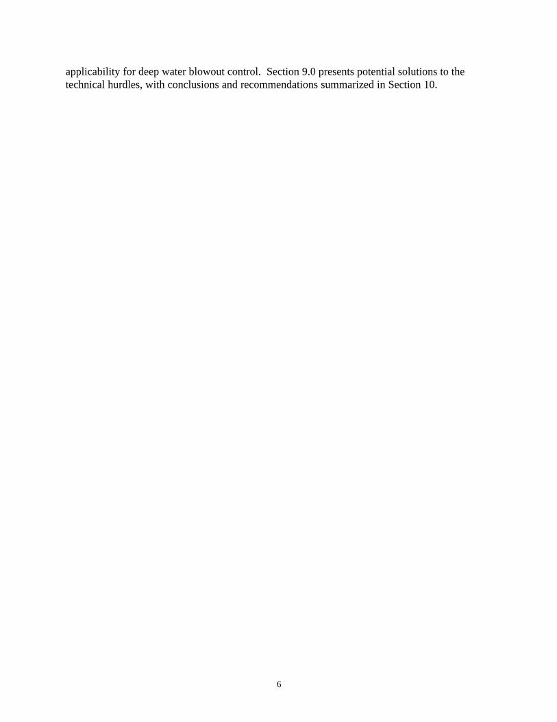
Current subsea drilling arrangements require that pressures caused by well influxes be containedat the sea floor. Riser systems are not designed to handle the pressures associated with kickremoval. These pressures are accommodated by the choke and kill line systems that extend fromthe subsea BOP stack to the surface, as shown in Figure 3.
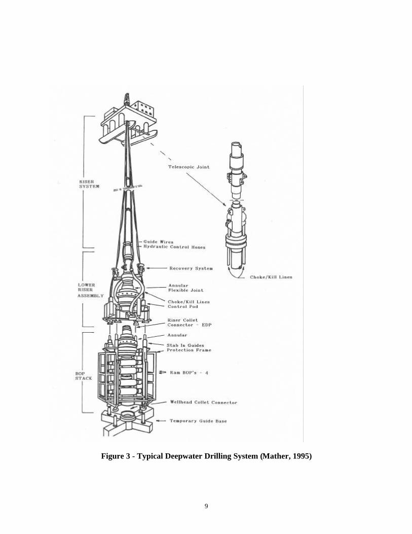
3.2.1 Subsea Wellhead Assemblies
The subsea wellhead provides a structural base for the casing strings as well as the other drillingpressure control components. It also provides a receptacle for landing the successively smallercasing strings on hanger assemblies that seal in the wellhead housing to form part of the passivepressure barrier system. Figure 4 illustrates a typical subsea wellhead assembly.
Modern wellhead systems employ complex metal-to-metal sealing technology and mechanisms.These seal systems make-up a primary component in the passive barrier system. A failure of acasing hanger seal would, in the event of pressure, allow that pressure to be imposed on the nextouter casing string and associated wellhead seal. Such a situation could cause underground flowfrom the reservoir to the sediment at the bottom of the outer casing (i.e. the casing "shoe"). Thisis known as an underground blowout. If the outer casing string or wellhead seal can notwithstand the imposed pressure, a blowout could erupt outside the wellbore (i.e. broach).
3.2.2 BOP StackFigure 5 shows a typical subsea BOP stack. The individual BOP cavities that make up the BOPstack are connected together with API standard flanges or hub connectors. The BOP stack ismodularized within a steel framework that reduces the stresses on these connections. Theconsequence of a leak from one of these connections depends on its position in the BOP stackand what, if any, pipe is in the BOP stack at the time of failure. The annular (or "Spherical")BOP is designed to seal on any size tubular in the BOP stack. Most annulars can create aneffective seal even when there is no pipe in the well. With the exception of the shear blind rams(SBRs), the ram preventers in the BOP stack are designed to seal around either one particularsize of pipe or on a certain range of pipe ODs (e.g., 2 7/8" to 5" or 3 ½" to 5", etc.). Thus, if aBOP connection leak were to occur anywhere along the BOP stack while, say, drill collars werein the BOP stack and the variable bore rams (or their control system) were not functioning itwould not be possible to isolate the leak with a pipe ram.
3.2.3 BOP Connectors (Lower & Upper)The BOP stack attaches to the wellhead housing with a hydraulically actuated connector ("LowerConnector" or "Wellhead Connector"). This connector provides a means to disconnect the BOPstack when required. The lower connector constitutes part of the passive barrier system duringdrilling and workover operations. It must be capable of maintaining a pressure seal equal to therating of the BOP components under high stresses imparted by the BOP stack and riser. Thisconnector is extremely critical since it is always below the BOP stack, see Figure 6.
9
Figure 3 - Typical Deepwater Drilling System (Mather, 1995)
10
Figure 4 - Subsea Wellhead Assembly

11
Figure 5 - Subsea 18 ¾” BOP, and Figure 6 - Vetco H-4 Wellhead Connector

12
The riser system can be detached from the BOP stack via a similar hydraulic connector "UpperConnector" or Lower Marine Riser Package (LMRP) Connector. Typical deepwater BOPsystems utilize a 4 or 5 ram/ 2 annular arrangement. One annular BOP (lower annular) is part ofthe BOP stack while the other (upper annular) is sometimes part of the LMRP, as shown inFigure 3. The LMRP also includes the electro-hydraulic control pods and the flex joint. In anemergency, a floating drilling rig might actuate the emergency disconnect sequence of activitiesthat includes (among a long list of activities):
• Hanging off the drill pipe on rams
• Shearing the drill pipe with specially designed rams (Shear Blind Rams/SBR). These ramsalso seal the wellbore after shearing the pipe.
• Disconnecting the upper connector and removing the LMRP and riser assembly
3.2.4 Choke and Kill Lines
Other sealing components on the BOP stack include the choke and kill line connectors (or"Stabs") and the choke and kill line valves. The BOP stabs are connected to the telescoping slipjoint at 180-degree phasing. In conventional water depths, these 3" lines are usually Coflexip orGoodall type hoses that range from 50 ft. to 75 ft. in length. (Figure 7) The sealing mechanismconsists of weight set seal arrangements accompanied by a support pin that is secured to the slipjoint. The deepwater BOP systems utilize a “hub” connection to secure the two lines to the slipjoint.
Some BOP stacks are arranged so that the kill/choke line is above the lower ram BOP cavity,others are not. API RP 53 (API, 1997) leaves the placement of such lines optional based on“preventer ram placement”. If the choke or kill line placement is below the bottom rampreventer, a leak at this connection would certainly be catastrophic since there would be nomeans to isolate it with a BOP.
All choke and kill lines used on LMRPs are required by industry standards to meet API 16 Ctesting requirements for choke and kill applications (API, 1993). The choke/kill lines meetingthis specification have had prototypes subjected to testing in an extremely harsh environmentwith continuous pressure cycling for a period of thirty days. At the end of the testing, the linesare subjected to rapid decompression and inspected for any separation or delamination ofmaterials.
All choke and kill line connectors have dual valve assemblies at the junction where they attach tothe BOP stack. At least one of these redundant valves must be a "Fail Safe" or "Fail Close"valve. This means that in the event that hydraulic control is lost, the valve will automaticallyclose. These valves attach to the BOP body via a standard API flange or hub connector. Just likethe connection between the BOP bodies, the consequences of a leak from one of theseconnections is dependent upon its position relative to the rams and what tubing is in the BOPstack at the time of failure.

13
Figure 7 - Choke & Kill Hoses in Moonpool
3.2.5 Riser/Slip Joint
The riser’s main function is to be a conduit from the subsea BOPs to the Mobile OffshoreDrilling Unit (MODU). This allows drilling fluids and cutting to be circulated through the rig’sactive mud system. There are two different types of riser couplings that are currently used today.For deepwater operations (Over 3,000 ft.) a flanged connection (HMF Type) is primarily used.(Figure 8.) In conventional water depths, an energized “dog” arrangement (MR-6C/D/E Type),as seen in Figure 8, is used. These designs have excellent integrity and historically theconventional water depth designs have not failed during well control operations.
Figure 8 – Riser Couplings

14
The telescoping joint or “slip joint” (Figure 9) is the weakest link in the well control equipment.Case histories have shown where gas in the riser has had catastrophic consequences. If gas isallowed to enter the riser, the diverter system is the only means to keep gas off the rig floor.Most diverter systems are low pressure rated and will not handle pressures greater than 1,500 psi.The packing elements are split or solid and can be operated by air or hydraulic pressure.
Figure 9 - Slip Joint
15
3.3 Subsea Completion Equipment
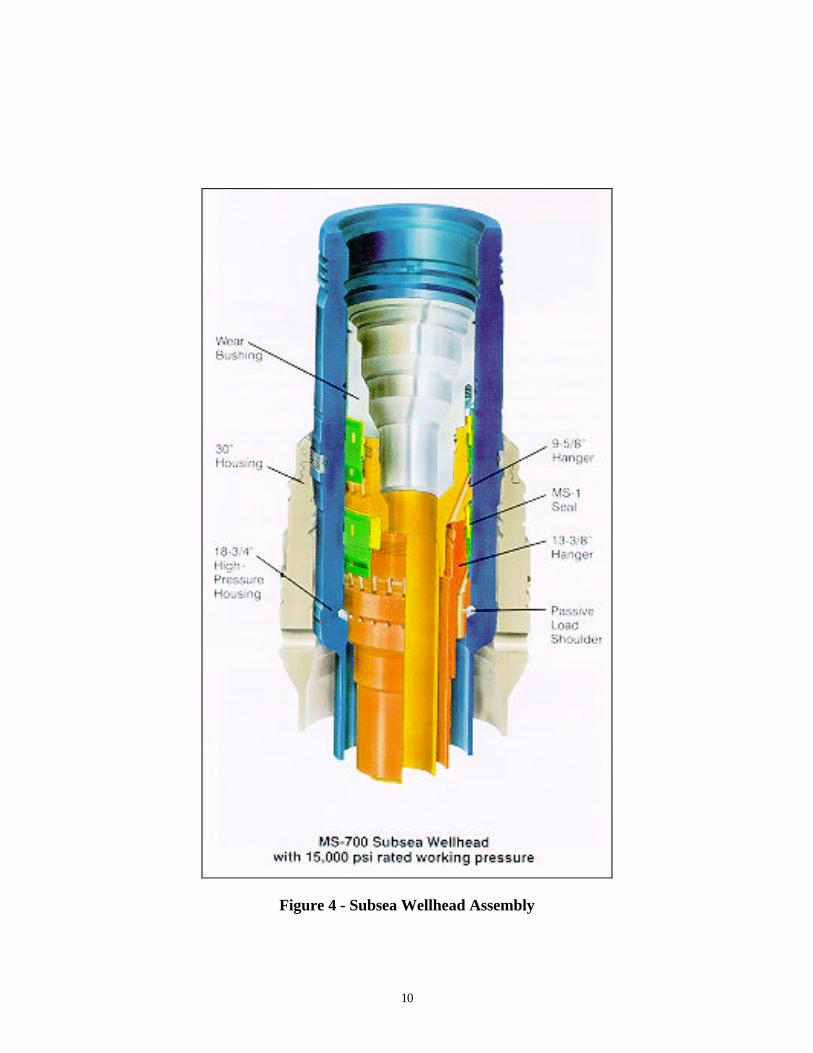
Wells in deepwater are normally produced through subsea production trees ("Christmas Trees").These can be either a "stand alone" system called a satellite well or they may reside on a subseatemplate with many other wellheads. Current deepwater production schemes include subseawelltemplates tied into fixed or floating production facilities or tied into a Floating Production,Storage and Offloading Facility (FPSO). In either case, the subsea well template may haveseveral satellite wells connected to it via seafloor pipelines.
A typical scenario is to drill the subsea well(s), complete them (i.e. install packers, tubing,SCSSVs, etc.) and install a production tree that connects to the wellhead housing that was usedduring the drilling phase. A typical subsea production tree is shown in Figure 10.
Figure 10 - Typical Subsea Production Tree
The connector where the subsea tree attaches to the wellhead housing is a critical component. Aleak from this connection can not be isolated via the tree valves. However, once a well is inproduction, other passive and active barriers exist for isolation. Examples of these include thetubing, packer and SCSSV.
Subsea trees include connectors where the flow line connects to the tree. These connectors aresimilar in nature to the choke and kill line connectors on a subsea BOP stack. These connectorsare always positioned so that they can be isolated with dual (redundant) valves on the flow sideof the tree assembly. They can also be isolated via the SCSSV assuming the tubing below theSCSSV remains intact.

16
4.0 Blowout Scenarios
The potential leak points on subsea drilling and production equipment are many. One of themajor components of safe drilling and production operations in the subsea environment isredundancy. Wherever possible, critical sealing and control mechanisms are backed up by atleast one redundant system.
The following deepwater blowout scenarios were developed by Wild Well Control Inc. based ontheir experience with subsea blowouts. As part of the scenario development, the relativelikelihood of a deepwater blowout occurring as described in the scenarios was ranked using theterms “low”, “moderate” and “high”. The relative likelihood assigned to each scenario wasbased on a critical component analysis as summarized in Section 5. Additionally, the relativeconsequence of the scenario was ranked using the descriptive terms “minor”, “severe” or“catastrophic”.
4.1 Drilling, Completion & Workover Blowout Scenarios
Possible scenarios for sustained blowouts during the drilling, completion and workover phasesinclude:
• through the riser, drill pipe/tubing, choke/kill lines at the rig
• through leak paths on the BOP/wellhead at the seafloor
• at the seafloor that are outside the wellbore (Broached)
These scenarios are not water depth dependent.
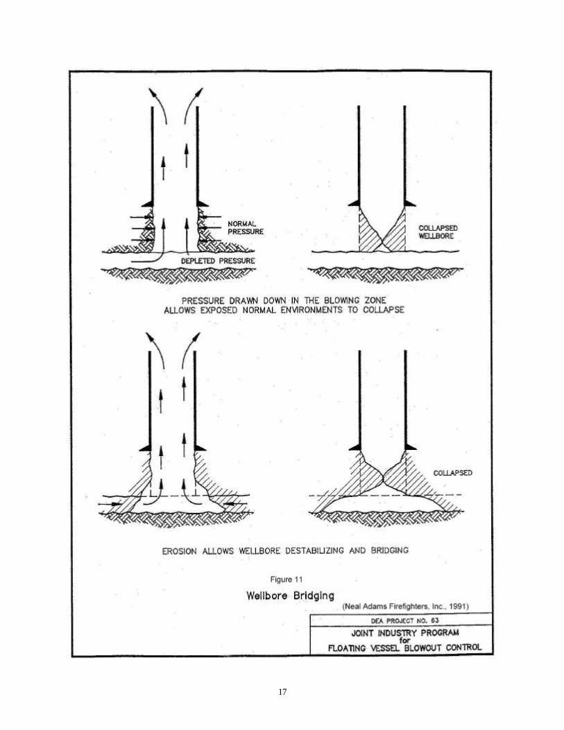
The major difference between a blowout during the drilling phase versus the completion orworkover phases is the drilling well tendency to "bridge off". Bridging is a phenomenon thatoccurs when severe pressure differentials are imposed at the well/reservoir interface, and theformation around the wellbore collapses and seals the flow path. See Figure 11. Such pressuredifferentials occur when a well is allowed to flow freely such as might be the case during asustained blowout. Deepwater reservoirs are notoriously susceptible to collapse under "highdraw down" conditions. Completion schemes often include methods to stabilize the reservoirduring production in order to reduce the production of solids in the flow stream. The mostpopular method is called a gravel pack completion. Thus, a completed well may not have thesame tendency to passively bridge off as would a drilling well involving an open hole (uncased)interval. The tendency to passively bridge may also be inhibited by the seawater column backpressure which may limit the flow rate and prevent collapse of the well. In these cases, activebridging methods may be considered to close the hole. Bridging may have a beneficial effect forspill control by slowing or stopping the flow of oil from the well.
There is a difference of opinion between blowout specialists on the likelihood of deep waterwells bridging off naturally in a fairly short time. There are a number of well characteristics thatmust be evaluated in order to accurately predict the probability of a particular deep water wellbridging off, including:• Reservoir Data
17

18
• Well Design• Casing Design• Seismic Data• Open Hold Data (length, size, etc.)• Blowout Effluent• Blowout Rate
A blowout could occur through the riser, choke or kill line or the drill pipe during the drillingphase (or tubing during the completion/workover phase). The first line of defense during thesephases is the hydrostatic pressure created by the mud column. This barrier can be compromisedby well influxes or losses of circulation. Suitable back up barriers exist for these situationsincluding the BOPs, casing and wellhead assembly. Figure 12 shows an example of a blowoutthrough a choke line hose.
Figure 12 - Blowout and Fire from Failed Choke Line
Example Blowout Scenario #1 (Through Riser)
Likelihood Rank: ModerateConsequence Rank: Severe
While tripping out of the hole with the drilling assembly (drill pipe, drill collars, etc.) anunexpected increase in the volume of mud returning to the mud tanks (influx) is observedwhile the 6 ½" OD drill collars are across the BOP stack. The lower annular is closed.Surface pressure increases beyond the pressure rating of the annular BOP (typically 5,000-psi). The Variable Bore Rams (VBRs) are actuated but will not operate. The shear blind
19
rams (SBRs) are actuated but fail to shear the drill collars (SBRs will not usually sheardrill collars) and seal the wellbore. The annular BOP suffers a sudden, catastrophic failureand the well flow is released up the riser. The flow destroys the diverter line at the surfaceand the telescoping joint on top of the riser is thrust through the drill floor.
Commentary: This is a possible scenario as the ability to implement the "method of last resort"(i.e. shear the pipe and disconnect) is not an option when items such as drill collars are in theBOP stack. Most influxes do not result in surface pressures beyond the rating of the annularBOP. However, some do by virtue of their intensity or being mishandled. It is not uncommon tofind that gas influxes are not handled correctly when the pipe string is shallow. Correct handlingin these situations requires the implementation of volumetric well control procedures that are notalways well understood by field personnel. Refer to the IADC deepwater Well ControlGuidelines (IADC, 1998) for well control procedures.
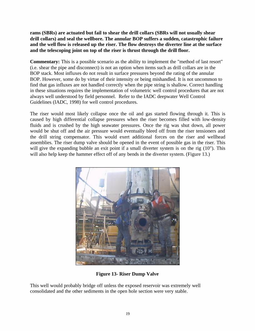
The riser would most likely collapse once the oil and gas started flowing through it. This iscaused by high differential collapse pressures when the riser becomes filled with low-densityfluids and is crushed by the high seawater pressures. Once the rig was shut down, all powerwould be shut off and the air pressure would eventually bleed off from the riser tensioners andthe drill string compensator. This would exert additional forces on the riser and wellheadassemblies. The riser dump valve should be opened in the event of possible gas in the riser. Thiswill give the expanding bubble an exit point if a small diverter system is on the rig (10"). Thiswill also help keep the hammer effect off of any bends in the diverter system. (Figure 13.)
Figure 13- Riser Dump Valve
This well would probably bridge off unless the exposed reservoir was extremely wellconsolidated and the other sediments in the open hole section were very stable.
20
Blowout Scenario #2 (Through Drill Pipe/Tubing)
Likelihood Rank: LowConsequence Rank: Catastrophic
During completion operations, the rig crew was pulling out of the hole after setting thegravel pack completion when an influx was observed. The well was shut in with theannular BOP and conventional circulation techniques were initiated to remove the influx.During the circulation, a hole developed in the tubing string at a connection (washout).High annular pressures caused by the influx near the seafloor (i.e., just below the BOPstack) communicated to the inside of the tubing string. The safety valve on top of the tubingbegan to leak where it was connected to the tubing string. Attempts were made to activatethe SBRs but they did not shear the pipe for unknown reasons. While the crew was makingrepeated attempts to actuate the SBRs, the leak at the top of the tubing string (i.e., at therig floor) increased dramatically as the mud was pushed out of the tubing and eroded theleak path. The rig was shut down and abandoned.
Commentary: This is a possible scenario but would require the complete failure of the SBRs.As stated in earlier sections, all control systems include a back up system. In this case, theredundancy is found in the dual multiplex control systems that include completely independentcontrol pods and surface actuation systems. Any scenario that involved sustained flow throughthe choke and/or kill lines would also have to involve the failure of the multiplex controlsystems. It should be noted that additional back up systems are available. These includeacoustically actuated controls and ROV intervention.
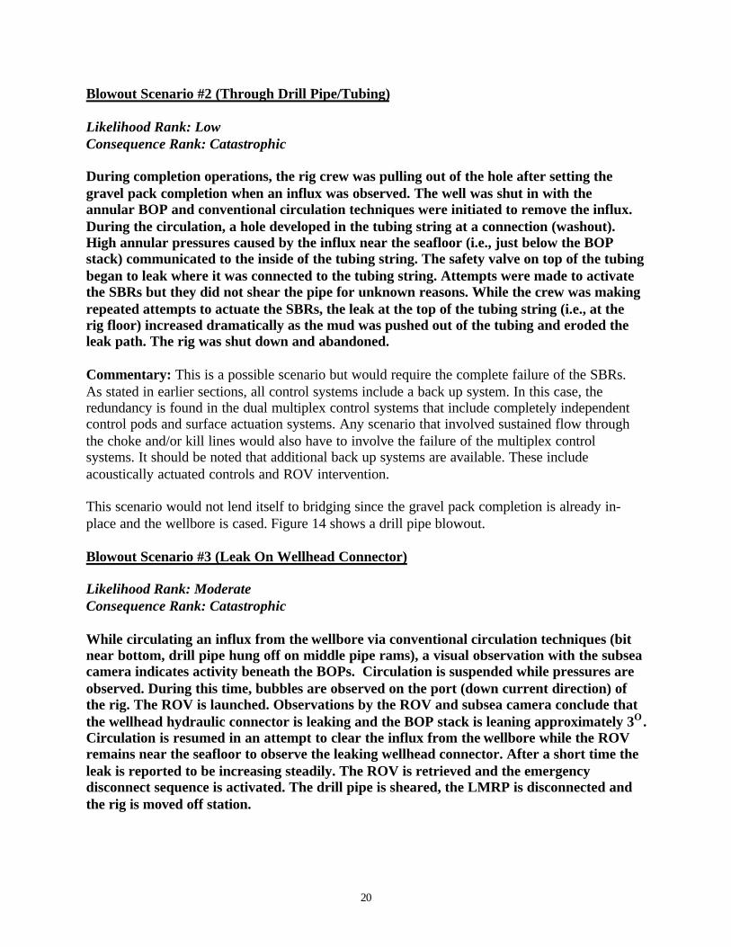
This scenario would not lend itself to bridging since the gravel pack completion is already in-place and the wellbore is cased. Figure 14 shows a drill pipe blowout.
Blowout Scenario #3 (Leak On Wellhead Connector)
Likelihood Rank: ModerateConsequence Rank: Catastrophic
While circulating an influx from the wellbore via conventional circulation techniques (bitnear bottom, drill pipe hung off on middle pipe rams), a visual observation with the subseacamera indicates activity beneath the BOPs. Circulation is suspended while pressures areobserved. During this time, bubbles are observed on the port (down current direction) ofthe rig. The ROV is launched. Observations by the ROV and subsea camera conclude thatthe wellhead hydraulic connector is leaking and the BOP stack is leaning approximately 3O .Circulation is resumed in an attempt to clear the influx from the wellbore while the ROVremains near the seafloor to observe the leaking wellhead connector. After a short time theleak is reported to be increasing steadily. The ROV is retrieved and the emergencydisconnect sequence is activated. The drill pipe is sheared, the LMRP is disconnected andthe rig is moved off station.
21
Figure 14– Drill Pipe Blowout
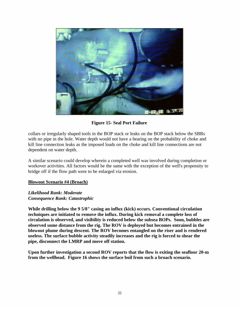
Commentary: This is also a reasonable scenario, as it is impossible to isolate the wellheadconnector with any of the rams. It should be noted that wellhead connectors (Figure 6) have anextremely good record of dependability. However, as deepwater activity increases so do theprobabilities of such a failure. In addition, increased water depths create higher bendingmoments on the subsea equipment, which, in turn, may increase the odds of a connector failure.If a control system failure were to occur, the wellhead connector may become unlatched, and thewellbore pressure may exit from below the connector or the seal ports. (Figure 15)
Even though this scenario involves a drilling well with an open hole section, the probability ofbridging is reduced since the leak is through a relatively small opening. This would reduce thepressure differential at the reservoir and cause a corresponding decrease in the volume of theflow. Erosion ,however, might cause the flow path to enlarge over time.
This scenario could be related to any leak on the BOP stack that could not be isolated with one ofthe rams. This would include choke or kill lines below the lowermost BOP, leaks with drill
22
Figure 15- Seal Port Failure
collars or irregularly shaped tools in the BOP stack or leaks on the BOP stack below the SBRswith no pipe in the hole. Water depth would not have a bearing on the probability of choke andkill line connection leaks as the imposed loads on the choke and kill line connections are notdependent on water depth.
A similar scenario could develop wherein a completed well was involved during completion orworkover activities. All factors would be the same with the exception of the well's propensity tobridge off if the flow path were to be enlarged via erosion.
Blowout Scenario #4 (Broach)
Likelihood Rank: ModerateConsequence Rank: Catastrophic
While drilling below the 9 5/8" casing an influx (kick) occurs. Conventional circulationtechniques are initiated to remove the influx. During kick removal a complete loss ofcirculation is observed, and visibility is reduced below the subsea BOPs. Soon, bubbles areobserved some distance from the rig. The ROV is deployed but becomes entrained in theblowout plume during descent. The ROV becomes entangled on the riser and is rendereduseless. The surface bubble activity steadily increases and the rig is forced to shear thepipe, disconnect the LMRP and move off station.
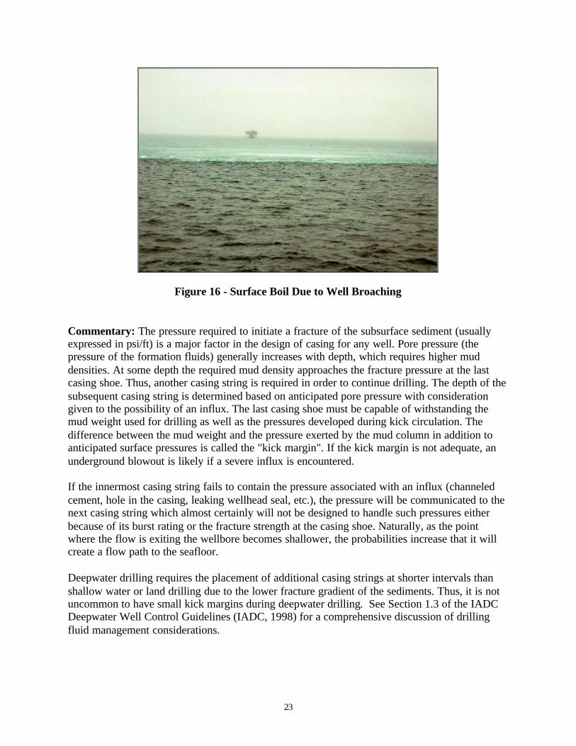
Upon further investigation a second ROV reports that the flow is exiting the seafloor 20-mfrom the wellhead. Figure 16 shows the surface boil from such a broach scenario.
23
Figure 16 - Surface Boil Due to Well Broaching
Commentary: The pressure required to initiate a fracture of the subsurface sediment (usuallyexpressed in psi/ft) is a major factor in the design of casing for any well. Pore pressure (thepressure of the formation fluids) generally increases with depth, which requires higher muddensities. At some depth the required mud density approaches the fracture pressure at the lastcasing shoe. Thus, another casing string is required in order to continue drilling. The depth of thesubsequent casing string is determined based on anticipated pore pressure with considerationgiven to the possibility of an influx. The last casing shoe must be capable of withstanding themud weight used for drilling as well as the pressures developed during kick circulation. Thedifference between the mud weight and the pressure exerted by the mud column in addition toanticipated surface pressures is called the "kick margin". If the kick margin is not adequate, anunderground blowout is likely if a severe influx is encountered.
If the innermost casing string fails to contain the pressure associated with an influx (channeledcement, hole in the casing, leaking wellhead seal, etc.), the pressure will be communicated to thenext casing string which almost certainly will not be designed to handle such pressures eitherbecause of its burst rating or the fracture strength at the casing shoe. Naturally, as the pointwhere the flow is exiting the wellbore becomes shallower, the probabilities increase that it willcreate a flow path to the seafloor.
Deepwater drilling requires the placement of additional casing strings at shorter intervals thanshallow water or land drilling due to the lower fracture gradient of the sediments. Thus, it is notuncommon to have small kick margins during deepwater drilling. See Section 1.3 of the IADCDeepwater Well Control Guidelines (IADC, 1998) for a comprehensive discussion of drillingfluid management considerations.
24
4.2 Producing Well Blowout Scenarios
Completed wells (i.e., those in production) present more severe consequences in the event of ablowout due to the hole being fully cased down to the producing formation, lowering theprobability of bridging. However, producing wells have numerous active and passive barriers inplace in addition to the normal redundancies found in all deepwater systems.
Subsea production trees attach to the wellhead housing connector in a fashion similar to the BOPconnector used during drilling. These trees often include redundant valves inline with the flowstream. These trees are fabricated in a single forged block to reduce the number of flange or hubconnections.
Subsea trees are monitored and controlled via electro-hydraulic and/or multiplex control systems.Pressure and temperature sensors continuously monitor the tree and the system is programmed toactuate active barriers at pre-set values. Any sustained blowout on a subsea production well willhave to involve failures of multiple active and/or passive barriers.
Blowout Scenario #5 (Tubing Failure Below SCSSV)
Likelihood Rank: LowConsequence Rank: Catastrophic
A satellite production well tied-back to a tension leg platform was automatically shut-in(SCSSV, master & wing valves closed) by the subsea control system due to high annularpressure. Shortly thereafter, a surface disturbance was reported by a standby vessel nearthe wellhead location. ROV inspection concluded that there was a flow exiting the wellheadhousing connector. The operator made arrangements to inject kill fluid into the subsurfacetree via the flow line. However, erosion created a flow path that caused all kill fluids to beejected at the wellhead.
Commentary: This situation could only develop if the tubing lost pressure integrity below theSCSSV and the tubing hanger seals failed and the wellhead connector failed.
Blowout Scenario #6 (Flow Line Damage)
Likelihood Rank: LowConsequence Rank: Catastrophic
A semi-submersible drilling rig was forced to make an emergency disconnect in heavy seaswhile drilling an offset satellite well near a FPSO facility. An anchor was unset during thedisconnect and pulled across a flowline from a nearby subsea well. The flowline was brokenoff at the connector causing an uncontrolled flow of oil and gas.
Commentary: This scenario would also have to involve multiple failures of redundant controlsystems. If a flowline were to be broken, the well would be shut-in (due to the sudden flowingpressure decrease) by the master valve, SCSSV and wing valves. Thus, this scenario is very

25
unlikely. This scenario would not likely occur in water depths roughly greater than 4,500 ft sincedrilling vessels in greater water depths are typically dynamically positioned.
Some flowlines are miles in length. The isolation valve may be located a great distance from theleak path. It may take quite some time to respond and physically close the isolation valve, whichwill continue to spill product into the ocean. Even after the valve has been closed, it will taketime to bleed down and clear the line.

26
5.0 Critical Component Analysis
The following table (Table 3) is a matrix, developed by Wild Well Control, indicating theranking of potential exit points according to the probability of occurrence. This ranking does notindicate the likelihood of a sustained blowout being caused by a leak at or through any of thepotential leak points. Such probability is included in the consequence ranking which follows (seeSection 6.0).
These summary tables give an indication of components which are likely sources of flow, andsource control, which should be addressed in well specific blowout contingency plans.
5.1 Drilling, Completion & Workover Operations
Possible failure points during drilling, completion and workover operations have beensummarized in Table 3. Based on their experience with the very few problems that have beenassociated with these components (which were described in Section 3.2) Wild Well Control Inc.developed the blowout scenarios contained in Section 4, which assigned a probability associatedwith the likelihood of a deepwater blowout occurring as a result of component failure. Theassignment of a probability was subjective, and based on Wild Well’s experience and judgement.They have assigned a moderate probability of a deepwater blowout to problems associated withthe wellhead connector, LMRP, well flow through the riser, or a broach. There is a lowerprobability of a deepwater blowout to problems associated with leak paths on the BOP, throughthe drill pipe/tubing or the casing hanger seals.
Blowout ProbabilityLow Moderate High
Wellhead Connector XBOP Flange/Hub Connection XChoke/Kill Connection to BOP XChoke/Kill Stab (LMRP) XThrough Riser XThrough Drill Pipe XBroach XCasing Hanger Seals X
Table 3 - Ranking of Potential Leak Points (Drilling/Completion/Workover)
5.2 Producing Wells
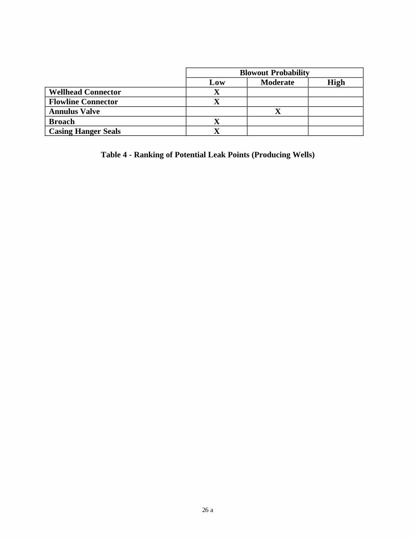
A similar table was developed for producing wells based on Wild Well Control’s experience.See Table 4. They have assigned a moderate probability of a deepwater blowout to problemsassociated with the annulus valve, while all other components were assigned a low probability.
26 a
Blowout ProbabilityLow Moderate High
Wellhead Connector XFlowline Connector XAnnulus Valve XBroach XCasing Hanger Seals X
Table 4 - Ranking of Potential Leak Points (Producing Wells)
27
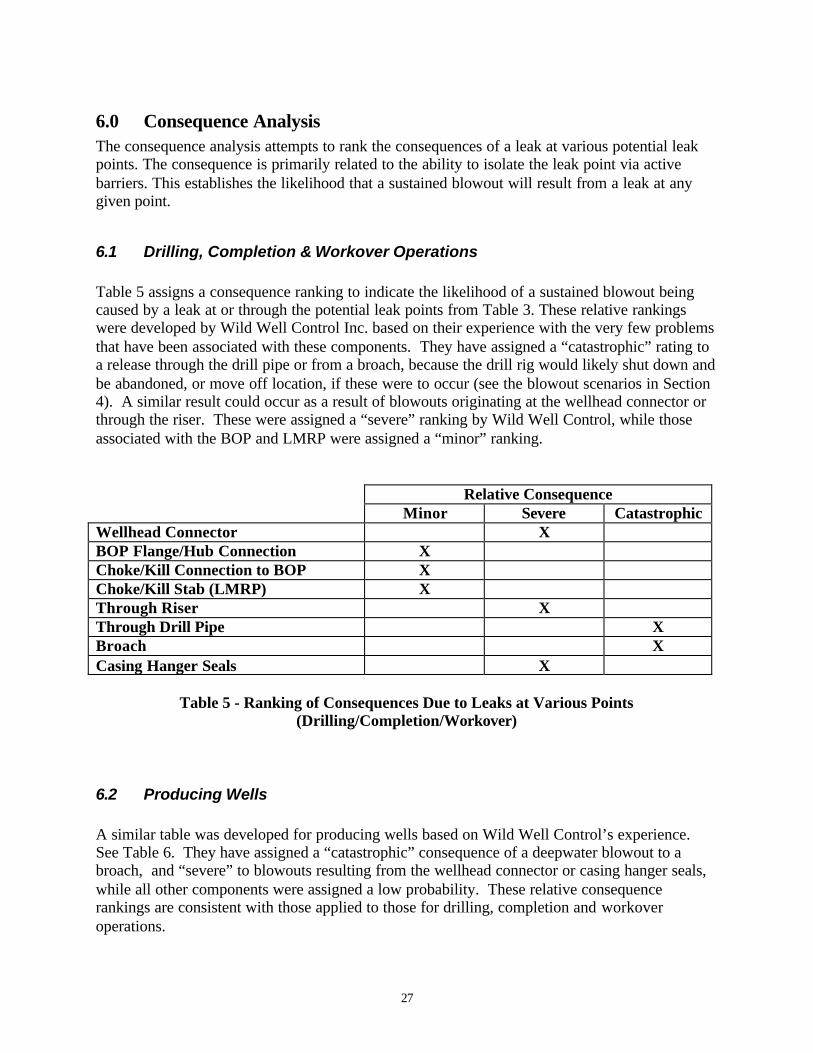
6.0 Consequence AnalysisThe consequence analysis attempts to rank the consequences of a leak at various potential leakpoints. The consequence is primarily related to the ability to isolate the leak point via activebarriers. This establishes the likelihood that a sustained blowout will result from a leak at anygiven point.
6.1 Drilling, Completion & Workover Operations
Table 5 assigns a consequence ranking to indicate the likelihood of a sustained blowout beingcaused by a leak at or through the potential leak points from Table 3. These relative rankingswere developed by Wild Well Control Inc. based on their experience with the very few problemsthat have been associated with these components. They have assigned a “catastrophic” rating toa release through the drill pipe or from a broach, because the drill rig would likely shut down andbe abandoned, or move off location, if these were to occur (see the blowout scenarios in Section4). A similar result could occur as a result of blowouts originating at the wellhead connector orthrough the riser. These were assigned a “severe” ranking by Wild Well Control, while thoseassociated with the BOP and LMRP were assigned a “minor” ranking.
Relative ConsequenceMinor Severe Catastrophic
Wellhead Connector XBOP Flange/Hub Connection XChoke/Kill Connection to BOP XChoke/Kill Stab (LMRP) XThrough Riser XThrough Drill Pipe XBroach XCasing Hanger Seals X
Table 5 - Ranking of Consequences Due to Leaks at Various Points(Drilling/Completion/Workover)
6.2 Producing Wells
A similar table was developed for producing wells based on Wild Well Control’s experience.See Table 6. They have assigned a “catastrophic” consequence of a deepwater blowout to abroach, and “severe” to blowouts resulting from the wellhead connector or casing hanger seals,while all other components were assigned a low probability. These relative consequencerankings are consistent with those applied to those for drilling, completion and workoveroperations.

27 a
Relative ConsequenceMinor Severe Catastrophic
Wellhead Connector XFlowline Connector XAnnulus Valve XBroach XCasing Hanger Seals X
Table 6 - Ranking of Consequences Due to Leaks at Various Points(Producing Wells)
28
7.0 Technical Hurdles to Deepwater Oil Spill Response
The following sections describe probable technical hurdles to be overcome in order to locate,contain, track and recover the uncontrolled flow of oil from the previously identified deepwaterblowout scenarios. Problems associated with identifying and correcting the cause of the blowoutusing well control techniques are discussed in the IADC Deepwater Well Control Guidelines(International Association of Drilling Contractors, 1998) and are not addressed here. Section 7.1identifies problems associated with subsea containment of oil from a deepwater blowout.Section 7.2 describes technical hurdles foreseen in the subsea injection of dispersants at thewellhead. Section 7.3 defines the problems related to released oil remote sensing and tracking.Section 7.4 identifies problems related to recovery of the oil if it reaches the sea surface. Theproblems identified in 7.1 through 7.4 are summarized in 7.5.
7.1 Subsea Oil Containment
7.1.1 Deepwater Currents
Deep water currents and the water depth itself will be a challenge for subsea oil containment.The availability of installation vessels with a suitable dynamic positioning system will be alimiting factor. In addition, the lack of information on plume formation and behavior will makeit difficult to predict areas where the oil might surface. Predicting the behavior of deepwatercurrents is a technical hurdle to be overcome for both relief well planning and for modelingplume behavior.
7.1.2 Manipulation of Heavy Objects
Intervention or containment at the wellhead may require the placement and/or removal of largeequipment pieces weighing several tons at depth. Manipulation of heavy objects on the seabedby means of a ROV can only be done in conjunction with surface support or subsea liftingdevices such as syntactic foam buoys, etc. The blowout area may be filled with debris from thesurrounding structure and pipes that have fallen down. In order to access the BOP one may haveto remove some of the debris, which could be very difficult to do. Existing technology for ROVsincludes hydraulic cutting devices in many different forms suitable for cutting nearly any steel orconcrete structure. In order to accomplish this, the ROV will need to move very close to theobject and must physically lock itself to it in order to complete the task. The blowout plume andsubsea current could make this a very risky and difficult task.
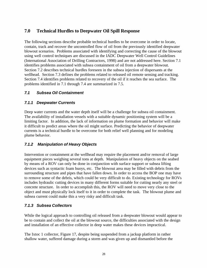
7.1.3 Subsea Collectors
While the logical approach to controlling oil released from a deepwater blowout would appear tobe to contain and collect the oil at the blowout source, the difficulties associated with the designand installation of an effective collector in deep water makes these devices impractical.
The Ixtoc 1 collector, Figure 17, despite being suspended from a jackup platform in rathershallow water, suffered damage during a storm and was given up and dismantled before the
29
Figure 17 – The IXTOC 1 “Sombrero” Collector
blowout stopped. When in operation, it only collected about 15% of the total flow. The balanceof the oil passed under the edge of the device because the gas lift riser was unable to transportthe enormous amount of water accompanying the oil (Westergaard, 1987). The 1,500,000bbl/day of effluent recovered by the system contained only 2% oil by volume. Surfaceseparation facilities were overloaded and one-half of the oil collected by this system wasdischarged over the side with the seawater (Neal Adams Firefighting, Inc, 1991).
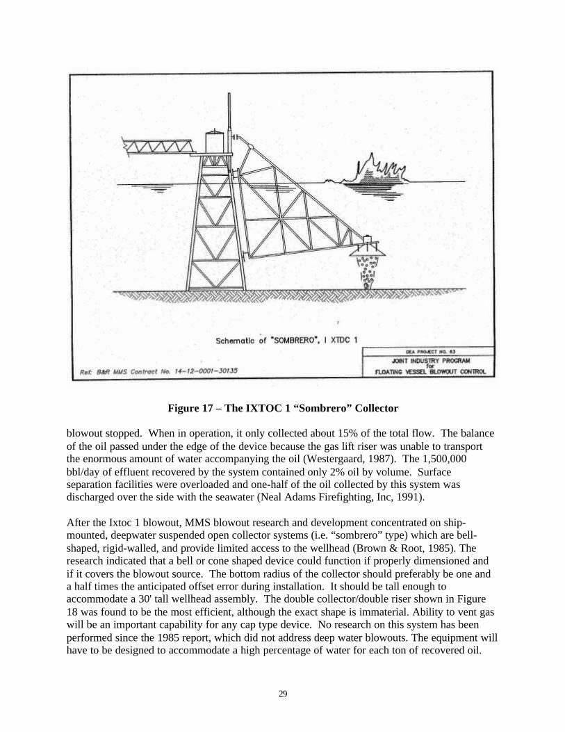
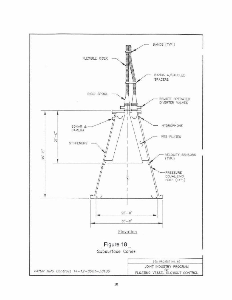
After the Ixtoc 1 blowout, MMS blowout research and development concentrated on ship-mounted, deepwater suspended open collector systems (i.e. “sombrero” type) which are bell-shaped, rigid-walled, and provide limited access to the wellhead (Brown & Root, 1985). Theresearch indicated that a bell or cone shaped device could function if properly dimensioned andif it covers the blowout source. The bottom radius of the collector should preferably be one anda half times the anticipated offset error during installation. It should be tall enough toaccommodate a 30' tall wellhead assembly. The double collector/double riser shown in Figure18 was found to be the most efficient, although the exact shape is immaterial. Ability to vent gaswill be an important capability for any cap type device. No research on this system has beenperformed since the 1985 report, which did not address deep water blowouts. The equipment willhave to be designed to accommodate a high percentage of water for each ton of recovered oil.
30

31
The dimensions of the device required to accommodate this volume, in combination with thewater depth handling requirements, makes the approach impractical and expensive given the lowprobability of blowout occurrence. The most serious limitation of the system is the cost, whichwas estimated at $58,784,000 in 1985.
The latest comprehensive summary of subsea blowout collection devices is contained in Section6 of the DEA-63 Project Report (Neal Adams Firefighting, Inc, 1991). This report generallycategorizes the collectors as bell-shaped devices, rigid-wall cylinders or flexible columns (SeeFigure 19). Among the technical hurdles associated with deepwater subsea collectors, thefollowing were included:
• They all limit access to the wellhead to some degree, and most prevent using other types ofwell control measures such as vertical intervention.
• They have limited tolerance for debris on the seabed.• None are in stock and few, if any will handle all blowout situations. Long lead times for
construction are anticipated.• They would require a seal against the seafloor to prevent entraining a large volume of
seawater in the plume. This situation may be mitigated if a subsea template can be installedaround the wellhead or BOP, to which the device can be attached.
• They would require a diameter sufficient to encapsulate the entire stack, with provision toaccommodate a leaning wellhead/stack assembly.
• Riser size is critical for bell systems. Small riser diameters result in a backpressure and spillunder of oil at the bottom of the bell.
• Rigid cylinders may be limited in deepwater because of the large surface area of the cylinderexposed to current forces along the water column. Heavy anchoring would be required.
• Flexible columns have been shown in laboratory experiments to suffer considerablewhipping and flapping associated with the flow of blowout fluids and gas. They lack theability to withstand significant pressure differentials across the walls.
These difficulties have caused most researchers to conclude that sealed containment of blowoutoil is not practical in deepwater with existing technology.
This conclusion was also reached in a recent evaluation of the state-of-the-knowledge andpractical opportunities for dealing with submerged oils that was recently published (Brown, et.al., 1998). The authors concluded that in most circumstances, it is not realistic to expectresponders to contain or recover submerged oils.
7.1.4 Installation and Approach
The installation of any oil containment device will need to be coordinated with well controlpersonnel. The blowout plume will make it difficult to approach the well with anything but verymassive equipment pieces or ROVs. The operation of ROVs will be difficult around the blowout point. The jet zone will cause vast amounts of water to flow towards the well. The danger ofhaving lighter equipment sucked into the flow is large. Many ROVs have been rendered uselessby relatively minor blowout plumes. A further complication is that conventional acoustic basednavigation systems or sensors on the ROV may not work as intended due to the heavy turbulencein the area. Both Acoustic Doppler Current Profilers (ACDPs) and ROV mounted tracking

32
acoustic systems may have problems due to diverted acoustic signals from the blowout plumegas. Air bubbles from the gas released in the 1996 Norwegian field trials simulating a blowoutevent (Rye and Brandvik, 1997) reportedly distorted the signals necessary for the underwaterpositioning system on both the ROV and research vessel (Brandvik, 1998). Alternate ROVcontrol methods will require development. Wells contained on subsea templates may not beaccessible with ROVs. Cratering of the sea floor around the well may also worsen the situation.A large crater will make access to the point of the outflow very difficult. Water will be pulledinto the stream along the seabed, at the same time sand and particles will be sucked into thestream from the surrounding crater.
The seafloor conditions in deepwater will probably be very unconsolidated. This may makemooring of any containment device to the seafloor difficult and could affect the placement ofheavy objects on the seafloor.
7.1.5 Lack of Standardization
Subsea well head and BOP design and operation are not standardized. Containment device sizeswould necessarily have to be flexible to fit a large variety of subsea well and satellite designs.Wellhead control options may be limited by the lack of standard manual overrides on subsea gatevalve stems or provision of wet stabs which might be used to exit flow or introduce kill fluids.
33
7.2 Subsea Dispersant Injection
One of the more promising solutions for dealing with a deep water out-flow of oil is to mix theoil with dispersant at the source. Experiments (Westergaard, 1987) indicate that this way ofdealing with the problem could be a practical and cost effective method. Only 1% by volumedispersant might be sufficient in order to treat the oil due to the good mixing which will be aresult from the violent and turbulent fluid stream. Technical devices and methods to inject thedispersants are not available and a number of technical hurdles can be foreseen. The majorhurdle is the method and apparatus for delivering the dispersion to the plume.
7.3 Oil Remote Sensing and Tracking
7.3.1 Understanding of Plume Dynamics
The deepwater currents cited as a technical hurdle for subsea containment will also affect theability to track the oil after it exits the well. The effects of currents, fluid type, and temperaturemust be taken into account. Plume theory modeling will be one of the important factors in theability to trace and project the oil trajectory after a blow out. If plume deterioration occurs,tracking of the oil will be a major hurdle. Reliable proven plume modeling and underwatertracking methods are not available and further research in these fields is needed.
7.3.2 Oil Properties.
The properties of the oil escaping the well will have a significant impact on the ability to track it.The oil properties will effect emulsification, dispersion and possibly whether the oil will rise tothe surface or stay submerged. The oil properties will change over time as the plume rises to thesurface. Stable emulsions may be formed. Natural subsurface dispersion is expected to besignificant with the shearing effects of multi-layered subsurface currents. Oil reaching thesurface will be subject to evaporation and other weathering processes. Unless a weatheringstudy of the oil properties is performed on a sample soon after the oil is found during explorationdrilling, these properties may not be known at the time of the blowout.
7.3.3 Detection
Although there are a number of techniques, which might be used for detection of submerged oil,none have proven very effective (Brown, et. al., 1998). Fluorometers have been used to detectsubmerged oil plumes; but large flat, thin layers or “blobs” of oil would not be detected by thismethod as they operate over a limited concentration range and detect only oil as it passes throughthe sampling tube. There is only one reported instance of acoustic techniques having been usedfor detecting and tracking submerged oil. SINTEF (The Foundation for Scientific and IndustrialResearch in Norway) used an ROV equipped with a sonar operating in the 450 - 650 kHz rangeduring their underwater releases of oil in 1995 and 1996 (Brandvik, 1998). The sonar wascommercial equipment made for fish finding. Images from the sonar, and a low light camera,were used to quantify the diameter and position of the plume relative to the release point and thesurfacing position. They succeeded in measuring the diameter of the plume vs. depth, but hadproblems fixing the position of the plume since the exact location of the ROV could not bedetermined. Air bubbles from the gas released in the 1996 field trial simulating a blowout event

34
(Rye and Brandvik, 1997) reportedly distorted the signals necessary for the underwaterpositioning system on both the ROV and research vessel (Brandvik, 1998).
FlemingCo environmental, Denmark, has proposed to Bitor Corporation the use of sonar for theunderwater remote detection of spilled orimulsion. Conclusions of a literature study – mainlybased on the observed success of the SINTEF efforts –led Bitor Corporation to sponsor a smallscale tank test of a spilled orimulsion underwater remote detection and monitoring system usingacoustic means. A 455 kHz multibeam forward-looking sonar was tested. The tank test, whichwas conducted by Fleming Hvidbak of flemingCo, occurred at a Danish refinery on April 27,1999. The sonar detected and monitored the Orimulsion cloud for 45 minutes after the release ofeight liters of orimulsion at a depth of 0.75 m in a 25 x 5 x 1.5 m (L x W x D) tank. Theorimulsion cloud was approximately 17 m away from the sonar (Hvidbak, 1999).
Sonar has also been suggested as being feasible by experts from SIMRAD, a manufacturer ofsonar and echo sounding equipment (Uzzell and Andersen, 1999).
7.3.4 Surface Oil Surveillance and Monitoring
After the oil reaches the sea surface, tracking can be accomplished using existing visual andelectronic systems deployed using fixed wing aircraft and helicopters. The usefulness of thesesystems may be limited by the remoteness of deepwater drilling sites from land and the ability ofaircraft to maintain station or track oil over a large area with a limited fuel supply. This potentialproblem might be overcome or aided by the use of space based imaging systems as discussed inSection 9.3.4.
7.4 Recovery of Oil on the Sea Surface
In addition to the research conducted on subsea collectors after the Ixtoc 1 blowout, MMSfunded the design and cost analysis of a ship-mounted surface collector for use during offshoreblowouts (Stewart Technology Associates, 1987). The system design required a retrofittedtanker with dynamic positioning capability situated downstream from the blowout. Two workboats deployed boom on either side of the ship to form a W-shaped collection system. Thecollected oil would be recovered into the tanker for treatment, storage and later transfer toanother vessel. The design called for the tanker to be equipped with a recovered oil processingsystem, dispersant spraying capability (via shipboard helicopter), extra booms, and a spillcommand center. As with the ship-mounted subsea collector described in Section 7.1.3, noresearch on this system has been performed since the 1987 report. The use of a dedicated tankerhull retrofitted to collect spilled oil makes the approach impractical and expensive given the lowprobability of blowout occurrence. The most serious limitations of the system are its cost, andthe fact that multiple systems would be required to provide coverage off different coastlines.Additionally, the amount of spill response equipment available to industry has dramaticallyincreased since the passage of OPA 90, making the study results near obsolete.
Surface oil spill clean up will have to rely on conventional methods and will likely have to makeuse of mechanical oil spill response equipment. The main hurdle will be of a logistic character ifvast amounts of oil reach the surface. If, for example, a stable water-in-oil emulsion is formedwith 20% oil content (MSRC, 1993) from an oil well producing 10,000 bbls/d one may

35
potentially have to deal with 50,000 bbls/d of emulsified oil. Even discounting emulsification,the Deepwater Well Control Guidelines (International Association of Drilling Contractors, 1998)cite a worse case deepwater well blowout of 30,000 to 40,000 bbls/day. Compounding thelogistics problem is the fact that deepwater oil fields are located farther offshore and farther fromthe sources of most spill countermeasures. For example, Shell’s Auger platform is locatedapproximately 255 miles southeast of Houston and 214 miles southwest of New Orleans. Thegreater distances may have implications with respect to the OPA ’90 tier response times and theability to support mechanical spill response efforts in the early hours of a response. The greaterdistance, however, will allow responders more time to prepare before there is a threat to ashoreline.
Storage of recovered oil may limit any recovery operations at deepwater blowout sites unlessprovisions are made to handle the large volume of recovered fluids and separate the oil from thewater on the oil spill response vessel (OSRV) or storage vessel. Currently, only the Marine SpillResponse Corporation’s OSRVs have recovered oil systems capable of breaking emulsions andwith oil water separators that will meet 15-ppm discharge standards.
Approximately 58% of the oil spilled by the IXTOC I well blowout was burned off at the surface(International Association of Drilling Contractors, 1998). If ignition of the surface oil ispossible, and it can be burned in a controlled safe manner, it should be ignited, and every effortmade to maintain the burn. The weathering properties of the oil, discussed in Section 7.2.2, willassist in determining if burning is an option. The ability to contain and sustain a controlled burnhas not been demonstrated for remote offshore locations.
7.5 Problem Summary
For subsea oil containment the technical hurdles to be overcome during a deepwater blowoutinclude:
• Predicting the behavior of deepwater currents• Ability to manipulate heavy objects on the sea bed• Ability to design subsea collectors that are flexible enough to cap a large range of subsea
wellhead assemblies and accommodate a high volume of recovered oil, gas and water• Ability to approach the blowing well and install containment devices on the seafloor• Lack of standardization in subsea wellhead design
For subsea dispersant application, these include:• Availability of equipment and methods for delivering the dispersants to the plume
For oil remote sensing and tracking, these include:
• Lack of understanding of plume dynamics• Lack of information on oil properties• Methods for detecting submerged oil plumes• Limited usefulness of surface oil surveillance and monitoring aircraft
For recovery of oil on the sea surface, technical hurdles include:

36
• Logistical problems for mechanical systems dealing with large quantities of recovered oil andwater at locations far offshore
• Ability to contain and sustain a safe, controlled burn at remote offshore locations has notbeen demonstrated
Likely solutions to each of these problems are developed in Section 9.

37
8.0 Blowout Patent Search
To ensure that solutions to the technical hurdles identified in Section 7.0 did not already exist,patent searches were performed in both Norway and the U.S. for blowout containment devices.Patents, which were thought to have potential application to provide deepwater containment, orwhich might have application as a spill countermeasure were copied for evaluation. The blowoutscenarios developed in Section 4 were used to evaluate the usefulness of the patented idea. Eachpatent was then assigned a classification using the following classification numbers to evaluatethe technical and economic viability of the different ideas in the patents:
1 Strongly water depth dependent. Can not be used in deep water2 Plume dependant. Behavior of plume may effect collector viability.3 Technically viable, but needs research and verification testing4 Technically not viable due to handling and operation considerations5 Economically not viable due to size, complexity and cost of operation6 Standardization impossible for use with any sub sea installation
The results are summarized in Tables 7 and 8. Comments on those that appear to be technicallyviable, but need further research and development, are provided in Section 9.1.3.
8.1 U.S. Patents
The U.S. patent search was conducted in the following manner. A search was conducted usingthe U.S. Patent and Trade Office web site (http://patents.uspto.gov) with the key words blowout,recovery, submerged oil, and oil spill. From this site it is possible to obtain copies of patentabstracts and numbers dating back to 1968. Using these, and patent numbers from the earlierliterature search performed by Brown and Root (Brown & Root, 1985), copies of the patentswere obtained at the U.S. Patent and Trade Office in Arlington, VA. The references cited in thepatents were then reviewed, and copies were made of those earlier patents that containedadditional information that might be of use in developing potential solutions for deepwaterblowouts.
Patent no. Name Description Classification3,389,559 Fluid recovery system and
methodFlexible sheet designed to contain theoil on the surface in a certain area
4
3,548,605 Submersible vehicle foremergency offshore gasleakage
Submersible support frame withcollapsible reinforced fabric to directthe flow to surface.
2,3,6
3,599,434 Device for confining oilreleased by leakage.
Deep skirted boom concept 1
3,643,741 Sealing of underwaterfissures
Well control by using polymerizingchemicals
Not applicable
3,653,215 Confining and collectingoil leakage
Surface deployed flexible fabric similarto 3,548,605
1,2,4,5
3,658,181 Underwater oil leakagecollecting apparatus
Device for directing flow into afloating structure
1,2
3,667,605 Submerged oil leak control Early version of the inverted funnelconcept
2,4,6
Table 7

38
3,674,150 Apparatus for preventingoffshore oil well pollution
Variation of the inverted funnelconcept
2,4,6
3,681,923 Apparatus for controllingsubnatant oil seepage
Fixed structure extending from theseafloor to the surface
1
3,719,048 Offshore structure withstatic dynamic stabilizationshell
Submersible inverted dome 5
3,746,097 Subsurface blowoutprevention
Down hole BOP system Not applicable
3,760,891 Blowout and lostcirculation detector
Method to detect a blowoutdevelopment
Not applicable
3,738,424 Method for controllingoffshore petroleum wellsduring blowout conditions
System for injection of gas to developan ice plug in the well
Not applicable
3,813,887 Apparatus for removingliquid contaminants from asubmerged tank
Apparatus for hot tapping into a tankand remove fluid
Not applicable
3,861,470 Method and apparatus forinside blowout preventerdrilling tool
Blowout preventer mounted inside thedrill string
Not applicable
3,879,951 Underwater drillingpollution control curtain
Flexible fabric sea curtain 1
3,885,629 Method and assembly forcontrolling blowout in oilwells
System for injection of CO2 to an oilwell thus creating an ice plug
Not applicable
3,926,256 Methods and apparatus forcontrolling and preventingblow out in wells
Method for injection of seal material inan oil well
Not applicable
3,981,154 System for recoveringpetroleum fluids fromunderwater fissures
Inverted funnel in flexible materialmoored to the seabed
2,4,5
4,163,477 Method and apparatus forclosing underwater wells
Method for remote closing ofunderwater wells by divers
1
4,283,159 Protective shroud foroffshore wells
Fixed piled system to create anenclosure around a fixed platform
1
4,309,127 Apparatus for controllingsubmarine leakage
Fixed structure from the sea bed to thesurface to contain oil spill
1
4,318,442 Apparatus for controllingan underwater blow out
Classic inverted funnel deployed froma large barge
5,6
4,323,118 Apparatus for controllingand preventing oilblowouts
Inverted funnel with valves located onthe seabed
5,6
4,336,843 Emergency well-controlvessel
Dedicated semisubmersible vessel forwell control
4,5,6
4,324,505 Subsea blowoutcontainment method andapparatus
”Sombrero” approach well documented 2,4,5
4,358,218 Apparatus for confiningthe effluent of an offshoreuncontrolled well
Bottom mounted collector tank 2,4,6
4,373,834 Portable offshore wellinstallation apparatus
Flexible skirt from seasurface to thesea bed
1
4,382,716 Blowout recovery system Inverted funnel with extended tubes foroil recovery
1
Table 7 (continued)

39
4,421,436 Tension leg platformsystem
Installation of tension leg platform overthe blowing well. Tension wires usedfor supporting the collection unit
3 (5)
4,456,071 Oil collector for subseablowouts
Collector launched from a jacketplatform
1
4,531,860 Deep sea oil salvagemeans
Bottom mounted collection chamberwith hoses to the surface
4,5,6
4,568,220 Capping and/or controllingundersea oil or gas wellblowout
Remote operated robot operating onpreinstalled rails.
3,5,6
4,643,612 Oil clean up barge Surface mounted dedicated barge forsurface oil collection
1,2,5
5,195,842 Oil spill tent Oil spill collection tent mountedbetween the sea bed and surface
1
5,213,444 Oil/gas collector/separatorfor underwater oil leaks
Surface mounted collector tank 1,2,5
5,289,883 Well casing-containedblowout preventer
Casing mounted blow out preventer Not applicable
5,704,732 Deep water piling method Suction anchors as piles for subseastructures as inverted funnels
6
Table 7 (continued) - Summary of U.S. Patents
8.2 European Patents
Our Norwegian team members at NOREN A/S conducted the patent search for European patents.These were reviewed, evaluated and ranked by PCCI and NOREN using the same classificationnumbers shown in Section 8. Patents from Norway, France and the UK were located and aresummarized in Table 8.
UK PatentsPatent no. Name Description ClassificationE02B 15/04E21 43/01
Equipment for therecovery of oil flowing outof sub-water ground
Surface mounted separator system withflexible skirt to the sea bed
1,2,5
1.601.462 Improvements in thecontrol of oil and gas wellblowout
System to improve the gas and oilmixing in conjunction with the use ofa subsea collector unit
Not applicable
2.063.776 Apparatus for subseacollection of oil leakage
Sub sea collector bell 1
2.134.159 Safety installation for asubmerged drilling wellhead
A remote controlled safety system toprevent blow out
3 (5)
2.150.614 Diverter/BOP system for abottom supported offshoredrilling rig
Surface mounted safety system duringdrilling
Not applicable
2.254.632 Controlling damagedwellheads
Clamp on system for installation ondamaged well heads
Not applicable
Table 8
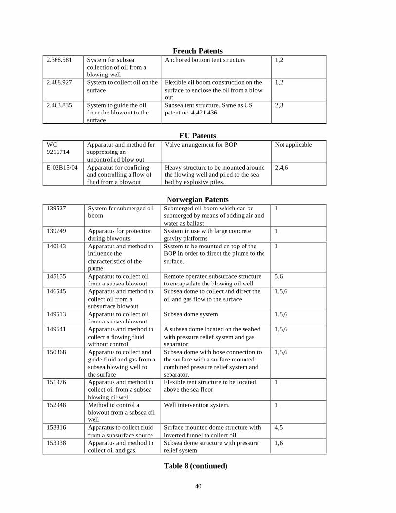
40
French Patents2.368.581 System for subsea
collection of oil from ablowing well
Anchored bottom tent structure 1,2
2.488.927 System to collect oil on thesurface
Flexible oil boom construction on thesurface to enclose the oil from a blowout
1,2
2.463.835 System to guide the oilfrom the blowout to thesurface
Subsea tent structure. Same as USpatent no. 4.421.436
2,3
EU PatentsWO9216714
Apparatus and method forsuppressing anuncontrolled blow out
Valve arrangement for BOP Not applicable
E 02B15/04 Apparatus for confiningand controlling a flow offluid from a blowout
Heavy structure to be mounted aroundthe flowing well and piled to the seabed by explosive piles.
2,4,6
Norwegian Patents139527 System for submerged oil
boomSubmerged oil boom which can besubmerged by means of adding air andwater as ballast
1
139749 Apparatus for protectionduring blowouts
System in use with large concretegravity platforms
1
140143 Apparatus and method toinfluence thecharacteristics of theplume
System to be mounted on top of theBOP in order to direct the plume to thesurface.
1
145155 Apparatus to collect oilfrom a subsea blowout
Remote operated subsurface structureto encapsulate the blowing oil well
5,6
146545 Apparatus and method tocollect oil from asubsurface blowout
Subsea dome to collect and direct theoil and gas flow to the surface
1,5,6
149513 Apparatus to collect oilfrom a subsea blowout
Subsea dome system 1,5,6
149641 Apparatus and method tocollect a flowing fluidwithout control
A subsea dome located on the seabedwith pressure relief system and gasseparator
1,5,6
150368 Apparatus to collect andguide fluid and gas from asubsea blowing well tothe surface
Subsea dome with hose connection tothe surface with a surface mountedcombined pressure relief system andseparator.
1,5,6
151976 Apparatus and method tocollect oil from a subseablowing oil well
Flexible tent structure to be locatedabove the sea floor
1
152948 Method to control ablowout from a subsea oilwell
Well intervention system. 1
153816 Apparatus to collect fluidfrom a subsurface source
Surface mounted dome structure withinverted funnel to collect oil.
4,5
153938 Apparatus and method tocollect oil and gas.
Subsea dome structure with pressurerelief system
1,6
Table 8 (continued)
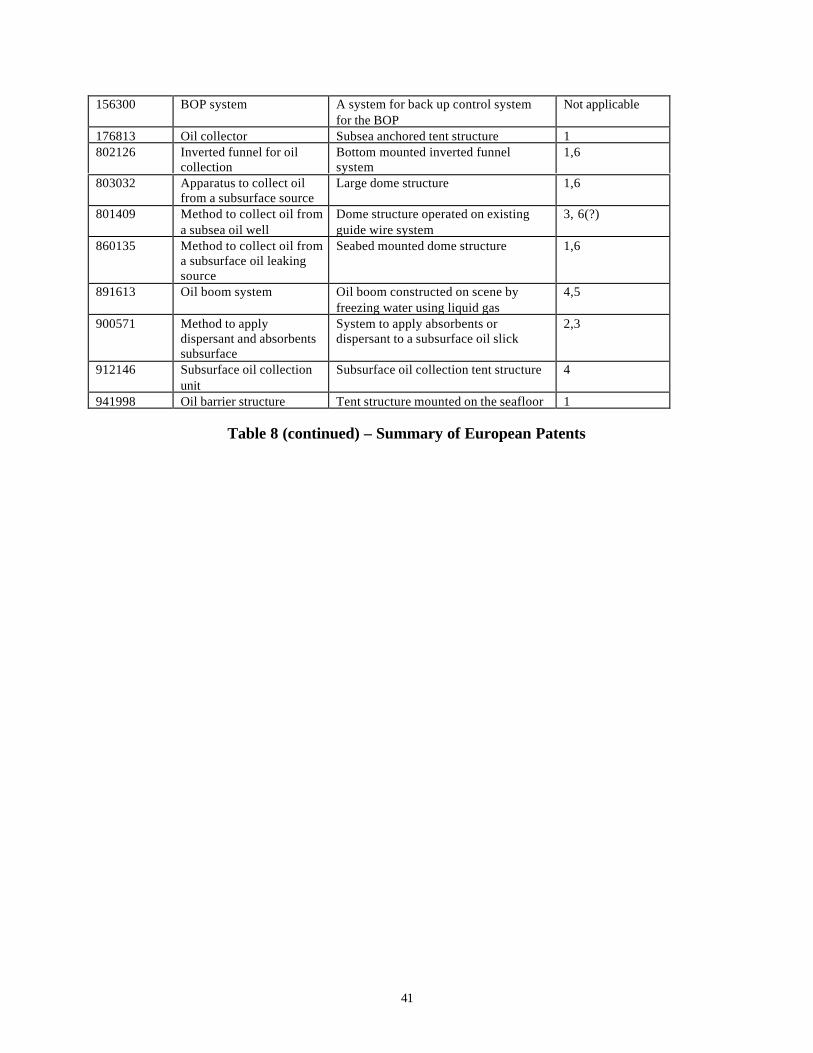
41
156300 BOP system A system for back up control systemfor the BOP
Not applicable
176813 Oil collector Subsea anchored tent structure 1802126 Inverted funnel for oil
collectionBottom mounted inverted funnelsystem
1,6
803032 Apparatus to collect oilfrom a subsurface source
Large dome structure 1,6
801409 Method to collect oil froma subsea oil well
Dome structure operated on existingguide wire system
3, 6(?)
860135 Method to collect oil froma subsurface oil leakingsource
Seabed mounted dome structure 1,6
891613 Oil boom system Oil boom constructed on scene byfreezing water using liquid gas
4,5
900571 Method to applydispersant and absorbentssubsurface
System to apply absorbents ordispersant to a subsurface oil slick
2,3
912146 Subsurface oil collectionunit
Subsurface oil collection tent structure 4
941998 Oil barrier structure Tent structure mounted on the seafloor 1
Table 8 (continued) – Summary of European Patents
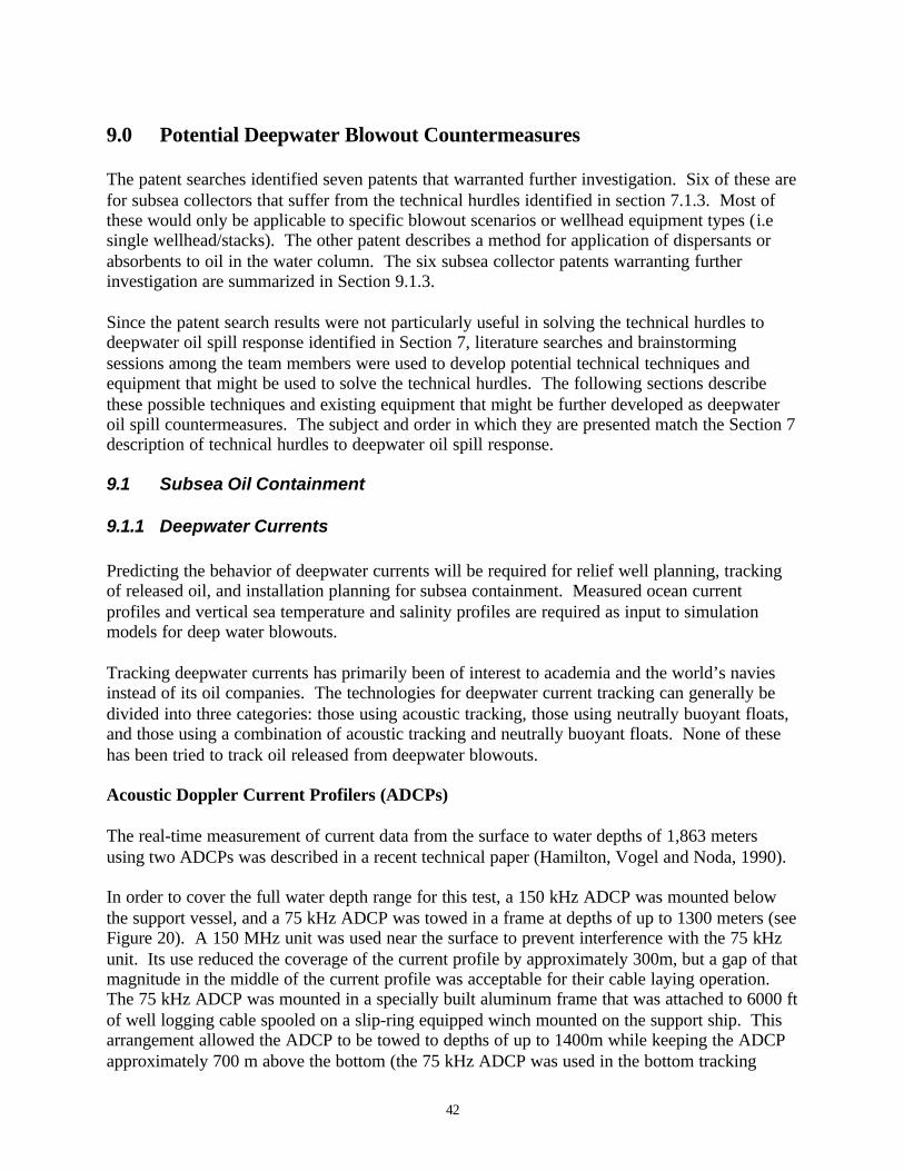
42
9.0 Potential Deepwater Blowout Countermeasures
The patent searches identified seven patents that warranted further investigation. Six of these arefor subsea collectors that suffer from the technical hurdles identified in section 7.1.3. Most ofthese would only be applicable to specific blowout scenarios or wellhead equipment types (i.esingle wellhead/stacks). The other patent describes a method for application of dispersants orabsorbents to oil in the water column. The six subsea collector patents warranting furtherinvestigation are summarized in Section 9.1.3.
Since the patent search results were not particularly useful in solving the technical hurdles todeepwater oil spill response identified in Section 7, literature searches and brainstormingsessions among the team members were used to develop potential technical techniques andequipment that might be used to solve the technical hurdles. The following sections describethese possible techniques and existing equipment that might be further developed as deepwateroil spill countermeasures. The subject and order in which they are presented match the Section 7description of technical hurdles to deepwater oil spill response.
9.1 Subsea Oil Containment
9.1.1 Deepwater Currents
Predicting the behavior of deepwater currents will be required for relief well planning, trackingof released oil, and installation planning for subsea containment. Measured ocean currentprofiles and vertical sea temperature and salinity profiles are required as input to simulationmodels for deep water blowouts.
Tracking deepwater currents has primarily been of interest to academia and the world’s naviesinstead of its oil companies. The technologies for deepwater current tracking can generally bedivided into three categories: those using acoustic tracking, those using neutrally buoyant floats,and those using a combination of acoustic tracking and neutrally buoyant floats. None of thesehas been tried to track oil released from deepwater blowouts.
Acoustic Doppler Current Profilers (ADCPs)
The real-time measurement of current data from the surface to water depths of 1,863 metersusing two ADCPs was described in a recent technical paper (Hamilton, Vogel and Noda, 1990).
In order to cover the full water depth range for this test, a 150 kHz ADCP was mounted belowthe support vessel, and a 75 kHz ADCP was towed in a frame at depths of up to 1300 meters (seeFigure 20). A 150 MHz unit was used near the surface to prevent interference with the 75 kHzunit. Its use reduced the coverage of the current profile by approximately 300m, but a gap of thatmagnitude in the middle of the current profile was acceptable for their cable laying operation.The 75 kHz ADCP was mounted in a specially built aluminum frame that was attached to 6000 ftof well logging cable spooled on a slip-ring equipped winch mounted on the support ship. Thisarrangement allowed the ADCP to be towed to depths of up to 1400m while keeping the ADCPapproximately 700 m above the bottom (the 75 kHz ADCP was used in the bottom tracking
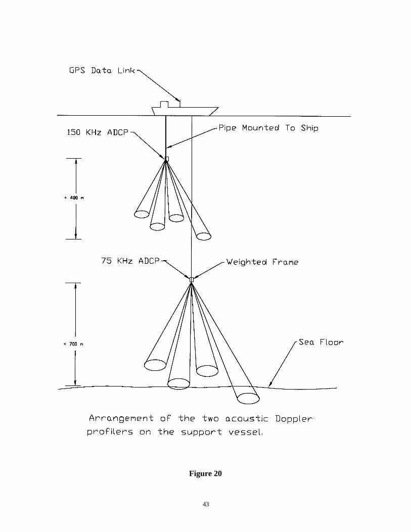
43
Figure 20

44
mode). The average depth ranges of the 150 kHz and the 75 kHz units were approximately400m and 700 m respectively. The data from these two ADCPs were corrected for the ship’svelocity and tow frame velocity. A central processing computer with output to a data acquisitionsystem, which received ship position and tow frame depth data to provide a true current profile,controlled quality. This system was quite complex and detailed planning and testing of thesystem were vital factors in making the current measuring system work successfully. Only withsimilar planning and testing, a deepwater ADCP system might be developed and kept ready fordeployment to track deepwater currents during a blowout.
Neutrally Buoyant Floats
Neutrally buoyant subsurface floats are less complex but unless coupled with acoustic trackingdo not provide real-time current data. The Autonomous Lagrangian Circulation Explorer(ALACE) is an example of a neutrally buoyant subsurface float which surfaces at regular pre-determined intervals to transmit temperature and pressure data, and be positioned by a satelliteGPS system before returning to its operating pre-determined depth. It was developed forapplications where acoustic tracking of buoys is not an option (Gould, 1998). There is no way ofknowing, however, where the buoys are until they surface. ALACE floats have been built tocarry a conductivity, temperature, depth (CTD) sensor packages and measure and transmitprofiles of temperature and salinity each time they surface. There are currently 17 ALACE floatsin the Gulf of Mexico operating to about 900 meters depth as part of the National OceanPartnership “Gulf of Mexico Ocean Monitoring System”.
The Autonomous Profiling Explorer (APEX), like ALACE, is an autonomous drifting profiler.Unlike ALACE, the APEX features active depth control, and can profile up or down from itsdrift depth. Webb Research Corporation manufactures both drifters. Data sheets on ALACE andAPEX floats are included as Appendix A. The ALACE floats cost approximately $10,000 eachwithout CTD sensors (Webb, 1998).
Floats with a continuous sound source or with acoustic receivers on the floats, where the soundsource is moored nearby, have also been developed for float tracking from an attending ship orusing the Navy’s SOund Fixing And Ranging (SOFAR) channel to a shore based listeningstation. The floats with acoustic receivers, known as RAFOS floats (the inverse of SOFAR)uploads the signal arrival times used for float tracking to a satellite system when the floatsurfaced at the end of its trajectory. These systems might also have application for tracking oilfrom deepwater blowouts but are much more complex than the ALACE floats and near the wellmight be hampered by the acoustic interference described in Section 7.1.4.
Tests of the usefulness of ADCPs and neutrally buoyant float systems should be performed andoperational methods developed for the deployment and use of the system best suited for use atthe time of a deepwater blowout. Additionally, these systems can be used to collect deepwatercurrent data which should be incorporated into spill response plans.
9.1.2 Manipulation of Heavy Objects
The best options for blowout spill containment may be in the areas of well control (which areoutside the scope of this study) and technologies for speeding the process of natural degradationof the released oil using dispersants applied at the wellhead (see Section 9.2). Both will require

45
the manipulation of heavy objects near the seafloor. Manipulation of heavy objects will berequired to promote self closure of the oil well by bridging, or to install subsea collectors.The merits of enforced bridging must be determined by well control specialists. The method cannot be standardized and has to be evaluated in each single case. Removing flow restrictions mayhelp enforce bridging. In order to evaluate this option in ultra deep water well control specialistswill need deep water suitable remote controlled tools as described below. Additionally, theremoval of flow restrictions to promote bridging will likely require regulatory approval, as it issimilar to allowing the purposeful discharge of oil from a tank ship in order to prevent the totalloss of the tanker and a larger spill.
Intervention at the wellhead will require the capability to place and /or remove large equipmentas described in Section 7.1.2. Conventional ROVs do not have a heavy object manipulationcapability. They can be used to make or break connections and assist with the recovery ofobjects on the seafloor. If they can lock on to a fixed object, they can be used to replace ringgaskets, BOP control hoses, and actuate hydraulic functions with ”hot stabs” (See Figure 21).ROVs can be used to re-establish guide wires or guide posts if they can get close enough to theBOP stack without becoming entrained in the blowout plume; however, they tend to have shortarms which would not allow them to get close to a blowing well.
The blowout site will normally be close to the seabed which could provide a base for a new typeof crawling ROV. A concept for such a system is described in Appendix B. A remotely operatedseabed based vehicle with a long manipulator arm may have the ability to assist with thedeployment of subsea oil contiainment devices, or intervene at the BOP by cutting and cappingstab-in connectors to the kill and choke line. The unit could be equipped with a long manupaltorarm with a reach of up to 45 ft. In order to withstand strong inflow currents and blowoutturbulance, the vehicle should be heavy. Weight is not a significant restriction as the operationalmode for the vehicle will be on the sea bed, and it does not need free swimming capability. Asuitable unit will be equipped with mulitple tools for cutting and advanced manipulator arms forattachment of wires for surface assisted heavy lifts. As described in Appendix B, the vehicle willoperate from a fixed installed platform at a maximum distance of 300ft from the blowout point.The platform will contain all necessary control systems and an electro hydraulic powerpack.Power from the surface will be supplied through a standard umbilical transferring electricity at7000 volt current. Hydraulic power can be supplied from the subsea platform to the workingvehicle by a flexible umbilical containing hoses for high and low pressure hydraulics as well assignal cable for operation of onboard solonid valves. Transfer of power for BOP system over-rides, repair, or to power underwater tools can be accomplished using ROV hot-stabs. DanfossA/S has recently introduced a series of water hydraulic components (using the tradenameNessie7) and in the future subsea equipment might be powered by water.
9.1.3 Subsea Collectors
Patents from the search described in Section 8 that were thought to have technical merit fordeepwater application are summarized below. These devices would require further research anddevelopment to overcome the technical hurdles described in Section 7.1.3.
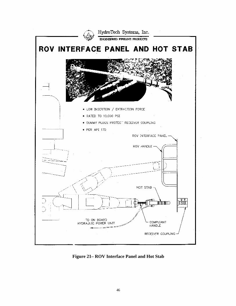
46
Figure 21– ROV Interface Panel and Hot Stab
47
9.1.3.1 Submergible Vehicle For Emergency Offshore Gas Leakage
Patent #: U.S. No. 3,548,605Date: 12/22/70Inventors: Peter L. Paull and Fontaine C. ArmisteadAbstract: Submersible support frame with a self contained collapsible reinforced fabricconduit to direct the flow to the surface where the oil can be recovered or burned.Comments: This concept deserves further research and development to study environmentaland deployment loads, and costs. It has potential for application to single well subsea structuresand minor leakage from a well. Its merits are that it would be relatively lightweight compared toinverted cone concepts, simple in principle, and could be quickly deployed. Its drawbacks arethat sizing of support frame to enclose well templates of various sizes would be necessary, andthe effects of weather on the surface containment device might be prohibitive.R&D Required: Flexible conduit dynamics, installation procedures for ultra deep water, controlsystems for ascent of the column to the surface, pressure and pressure balance on the conduit,and recovery methods after use.
9.1.3.2 Tension Leg Platform System
Patent #: U.S. No. 4,421,436Date: 7/6/82Inventor: Robert B. BurnsAbstract: A tension leg platform system for collection of oil leakage from a subsea structurethat incorporates a submergible hull that can be controllably lowered down the tension legmembers to the ocean floor with a canopy to cover the uncontrollably flowing well and conductthe effluent to the water surface.Comments: The patent has some potential when used with a tension leg platform. The tensionwires will form a fixed connection to the seabed and may secure the invention. Oil and gas maybe directed to the surface by a large riser connected to the top of the tent like structure.R&D Required: A reliable method for installation and operation, and a method fortransportation and storage of the structure have to be developed. Fluid dynamics and plumeformation will be deciding factors it is questionable if the tension leg platform will remain inposition in case of a major blowout.
9.1.3.3 Capping and/or Controlling Undersea Oil Or Gas Blowout
Patent #: U.S. No. 4,568,220Date: 3/7/84Inventor: John HickeyAbstract: Describes a system for capping and controlling a blowing BOP or wellhead. Thesystem contains a seabed rail mounted remote operated vehicle with heavy lift capability. Aspecial clamp capping system is proposed. The vehicle will move on the seabed on thepreinstalled rails and enclose the blowing well by the use of a special clamp on dome.Comments: The invention is based upon the assumption that it will be possible to establish anew practice for subsea installation. A new type of well structure with a rail system has to be
48
installed as part of the well structure. The remote operated vehicle will be installed on the railonce a blow out occurs. The system would be part of a special contingency system for blowouts.The system will only be possible to use if the leaking oil is coming from the BOP or the wellhead itself.R&D Required: A System for multiple wellheads has to be designed, a cost benefit analysiswill have to be carried out, it might be possible to develop the concept further in order for it to bemore versatile
9.1.3.4 Wire Supported Collection System
Patent #: FR No. 2,463,835Date: unknownInventor: unknownAbstract: This patent is similar to US patent No. 4.421.436. The tent like structure issupported by 4 floating structures. These are connected to the sea floor and act as supports forthe structure.Comments: See comments to US patent No. 4.421.436R&D Required: See comments to US patent No. 4.421.436
9.1.3.5 Safety Installation for a Submerged Drilling Well Head
Patent #: U.K. No. 2,134,159Date: 4/4/72Inventor: Georges Vigouroux, Gilbert Fort, Louis Marie SoleilleAbstract: Describes a predesigned system for emergency intervention to the oil well. Apredesigned well head will make use of a remote located umbilical drum located on the seabed atsome distance from the well. By using a drill string from the surface, a hose may be connected tothe wellhead through a stab-in connector. The drill string will connect to the hose drum structureand thus establishing connection to the wellhead for injection of well kill fluid.Comments: The invention is based upon the assumption that it will be possible to establish anew BOP design practice. The new BOP design will have to include stab in connection foraccess to the kill and choke line. The system will also be dependent upon the availability of asuitable advanced deep ocean drilling vessel. Once the system is established one will thus beforced to choose between well intervention and drilling a relief well.R&D Required: A new BOP design practice would have to be established, and new operationalprocedures would have to be established.
9.1.3.6 Apparatus and Method to Collect Oil from a Blowout
Patent #: NO 801409Date: 5/13/80Inventor: Fred H. Kooka, David CulverAbstract: Describes a system consisting of a subsea dome structure with a surface collectionsystem. The dome structure makes use of the existing guide posts and guide wires on a subseatemplate.Comments: The invention differs from other dome structures in the operational description ofthe system. It may be used if the blowout comes from the BOP and if there is no damage to the
49
structure on the seabed. It also requires existing, intact guide posts and that the BOP is located ona subsea template. The dome is lowered on guide wires or by using a drill string. It enters theexisting guide posts and locks to the subsea template. The operation may be applicable if there isa minor leak from the oil well.R&D Required: Methods for deep sea installation would have to be investigated, operationalprocedures and methods would have to be developed, and flow characteristics would have to bedetermined
9.1.4 Installation and Approach
The blowout plume will make it difficult to approach the well with anything but very massiveequipment pieces or ROVs. The operation of ROVs will be difficult around the blow out point.The jet zone will cause vast amounts of water to flow towards the well.
The installation of any subsea collector must be coordinated with well control personnel toensure that there is no interference with ongoing well control operations.
The potential for acoustic interference to navigation systems from a blowout needs to beresearched further to determine the best possible solution. Potential solutions include the use ofan inertia navigation system (as proposed for the multipurpose deepwater crawler in AppendixB), or possibly tuning the acoustics to a bandwidth not affected by the release of gas. TheUniversity of Liverpool has reportedly worked on the use of underwater RF transmission forapplication to positioning a deepwater ROV with respect to its deepwater docking station. Finetuning of this system is expected to occur during basin tests in France (Offshore, 1998).Development of this system should be monitored for potential application to this problem.
9.1.5 Standardization
The lack of standardization in subsea well head and BOP design and operationscan only be addressed through the development and application of well conceived standards forsubsea equipment. These standards must address the design of both the subsea well equipment(i.e. overrides) and ROV equipment and tooling. One option is the proposed API 17H SinglePoint Docking Unit shown in Figure 22 (Frisbie, 1998) which would standardize the equipmentmodifications required to optimize ROV support capabilites by addressing the location and typeof docking/handholds, marking and identifiction criteria for low visibility operations, and thedesign and orientation of selected overide functions.

50
Figure 22 – Single Point Docking Unit
9.2 Subsea Dispersant Injection
Enforcing the dilution of the released oil in the water column, in order to speed naturaldegradation, by injecting dispersant into the well or into the jet zone of the blowout is one of themost promising spill countermeasures identified.
Two concepts for the injection of dispersants into a blowout plume were developed earlier andare presented in the DEA –63 Report (Neil Adams firefighters, Inc., 1991). One of the conceptsrequired the installation of a special injection spool or port for dispersant injection in the subseastack or BOP itself (see Figure 23). An injection hose would lay on the seafloor connected to apendant buoy which could be recovered by a vessel of opportunity and the dispersant could bepumped into the plume. Another concept showed the dispersant injected from the wellborethrough a tube connected to a side pocket mandrel or down an open annulus in a platformdrilling operation (Figure 24). Both of these concepts require pre-planning to incorporateequipment for dispersant injection into the design of drilling and production equipment.
Neither concept would work for the scenario invoving a broach, or if wellhead/stack is not intactor the injection line has been damaged. Thus the report recommended the development of awellhead independent device that would be simple, easy to fabricate , transport and install withlittle additional technological development. The cone shaped flow through device shown inFigure 25 was recommended, with nozzles arranged around the periphery at the top of theopening for injection of the dispersant. The device would be anchored over the blowout source.

51
Figure 23 – Concept For Subsea Dispersant Injection At The Wellhead
The top of the device would behave like an educator. The dispersant would be drawn into theplume by the venturi effect. An advantage of this design is that the shape of the device wouldallow vertical intervention well control methods to be used while the effluent is being treated.As this device could be used in all of the subsea release scenarios developed in Section 4, itcould be constructed as blowout contingency equipment item that could be stored along withadequate stocks of dispersant in an OSRO’s inventory.
Subsea testing of dispersant injection into a blowout plume is required to validate this as apotential blowout oil spill countermeasure. Equipment and methods for the delivery ofdispersant to the blowout source require developed. Further research is required to to determinethe injection nozzle design, methods and ratios for subsea dispersant injection to be effective andtake advantage of plume dynamics to enhance mixing. For the device shown in Figure 25, thenumber and size of nozzles needed for adequate dispersant for a given throat diameter; a suitableanchoring system; storage tank dimensions; and dispersant supply pumping, monitoring, andcontrol systems; would need to be designed and tested.
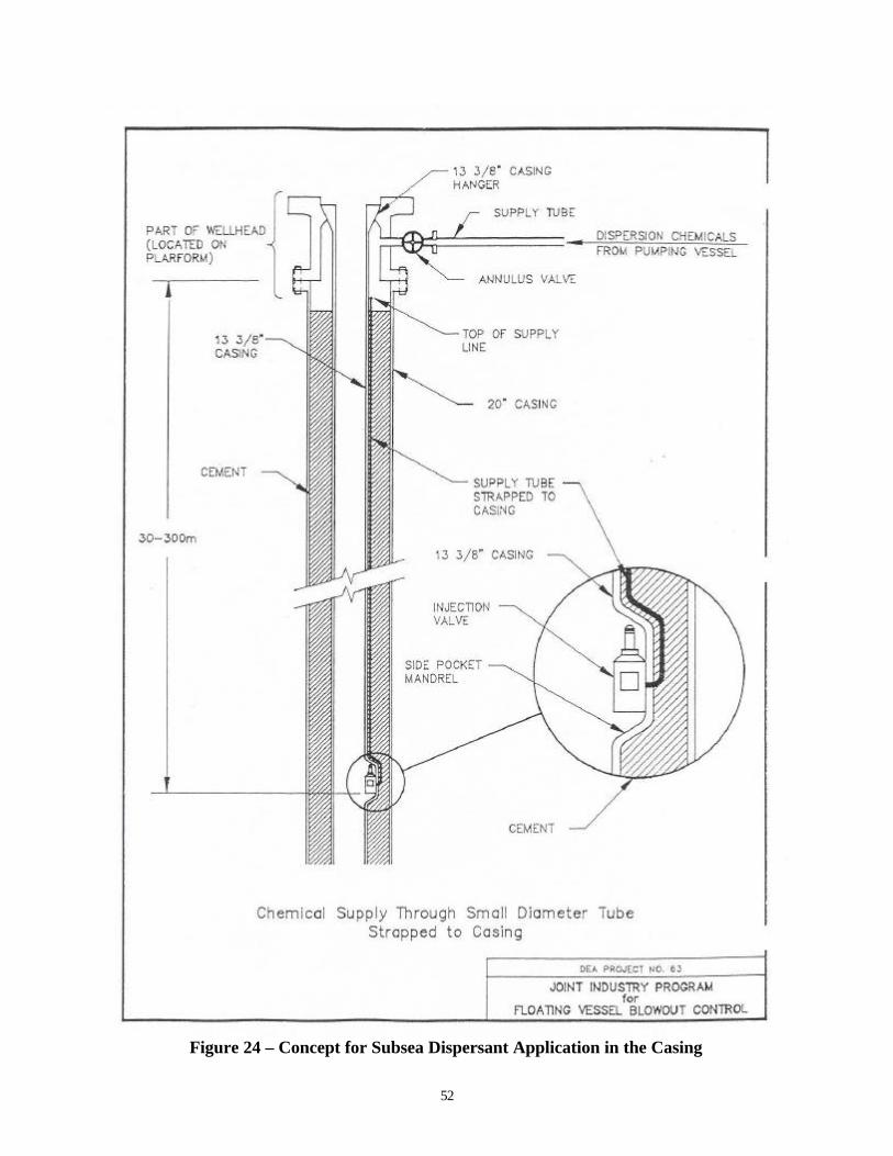
52
Figure 24 – Concept for Subsea Dispersant Application in the Casing
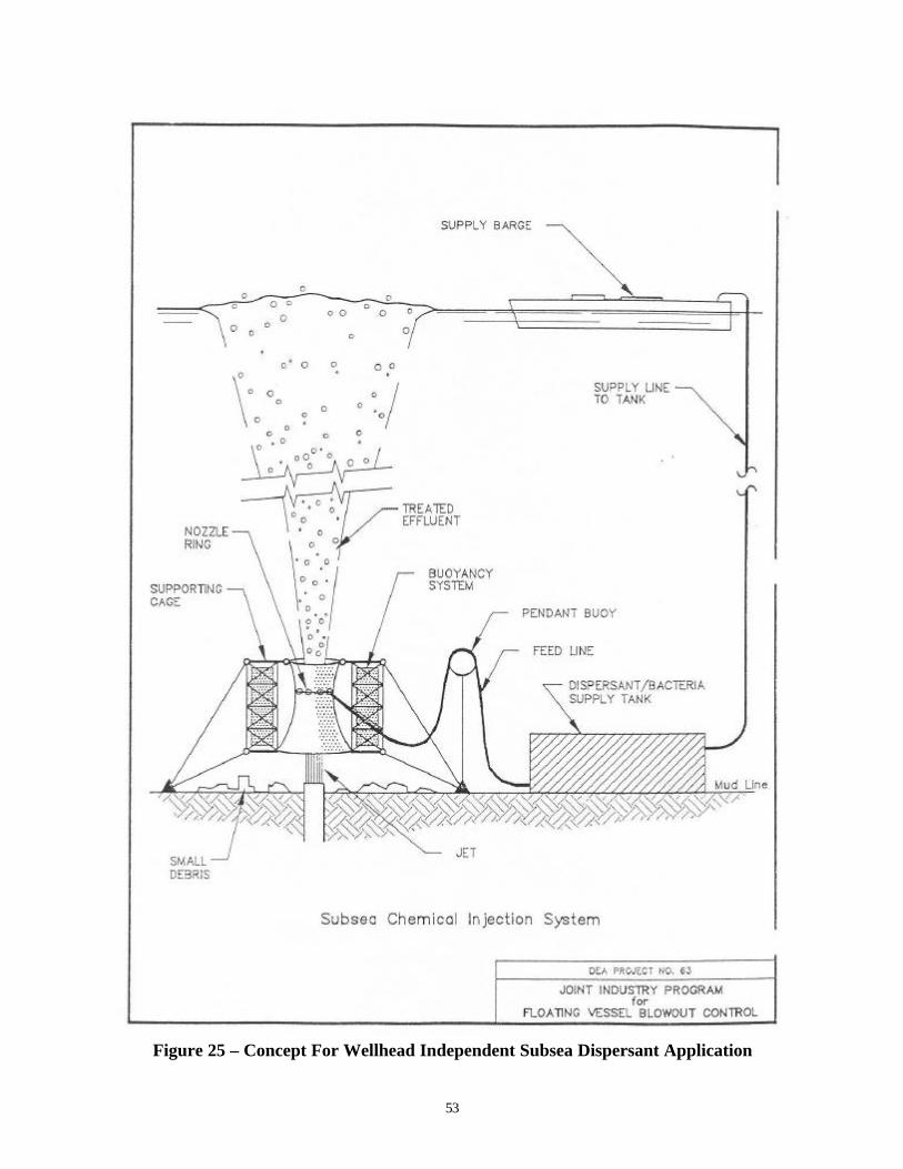
53
Figure 25 – Concept For Wellhead Independent Subsea Dispersant Application

54
A remotely operated seabed based vehicle, as described in Appendix B, with a long manipulatorarm could also be designed to have the capability to use nozzles for injecting dispersant directlyinto the jet zone of the blowout.
9.3 Oil Remote Sensing and Tracking
9.3.1 Understanding of Plume Dynamics
As noted in Section 7.3.1, the ability to model and predict plume dynamics, for tracking the oilreleased from a deepwater blowout, should be a priority research area. This is especially true forultra deepwater, since present computer blowout models are relatively simplistic and cannotmodel the effects of high pressure, hydrate formation, subsurface currents, and stratification.
Modeling
Research efforts to expand the capabilities of subsurface blowout and release models are plannedor underway at organizations including Applied Science Associates, Inc. (Spaulding, 1998),Chevron (Alan, et. al., 1997), Clarkson University (Zheng and Yapa, 1999), and SINTEFApplied Chemistry. Sufficient data to validate the predictions are the key for any model toproduce realistic results. Efforts are underway to collect both experimental data (University ofHawaii, 1998) and offshore test release data, and these should be an integral part of any modeldevelopment effort. Offshore test releases would also be an opportunity to test the equipmentdescribed in Sections 9.1 and 9.2 (i.e.: equipment for current tracking, manipulating heavyobjects, and subsea dispersant injection) and the equipment described below for real timeimaging of a blowout plume.
Real Time Imaging
It should be possible to make measurements of a blowout’s plume jet zone diameter and heightusing sonar and other sensors. Images of the formation fluid flow can be compared to knowndimensions on the BOP stack. High speed images of the plume can be used to estimate velocityby using bubbles or other discontinuities in the flow and measuring distance traveled betweensuccessive pictures (International Association of Drilling Contractors, 1998).
SINTEF used an ROV equipped with a sonar operating in the 450 – 650 kHz range during theirunderwater releases of oil in 1995 and 1996 (Brandvik, 1998). The sonar was commercialequipment made for fish finding. Pictures from the sonar, and a low light camera, were used toquantify the diameter and position of the plume relative to the release point and the surfacingposition. They succeeded in measuring the diameter of the plume vs. depth, but had problemsfixing the position of the plume due to problems determining the exact location of the ROV (See7.1.4).
A number of underwater imaging systems that make use of extremely low light level cameras areavailable and may have application to this problem. Two technologies are of particular interest.One is the high dynamic range Charged Coupled Device (CCD) camera, similar to the onedeveloped by Roper Scientific Trenton (formerly Princeton Instruments, Inc.) for Woods HoleOceanographic Institution. The other is the range gated intensified CCD (ICCD).
55
A CCD camera consists mainly of a silicon chip that collects electrons that are excited into theconduction band. In other words, light from the object being imaged interacts with the siliconthereby releasing electrons that are collected in pixels, and then readout to a computer. When allthe pixels are emptied into the computer, the computer displays a digital image of each of thepixels and the amount of light each collected, this produces a grayscale image of the object in thefiled of view. Recent use of CCD cameras for deep underwater imaging to depths of 6,000meters is described in the article by Goldsborough III, et. al., 1998. New hardware and softwareto extend the imaging capabilities using laser illumination and computer image simulation aredescribed in Jaffe, et.al, 1998. Benefits of CCD technology include the immediate availability ofthe image; the ability to digitally manipulate, store and display the images; and the ability toapply digital-image processing techniques to enhance specific image features.
The high dynamic range CCD will be adversely affected by the turbulence and turbiditydescribed in Section 7.1.4. There is some chance that by virtue of its higher dynamic range, thedesired image information may still be visible through the "virtual fog" of the turbidity. It mightrequire quite sophisticated image processing to recover the desired information from the images.Whether or not this is possible is probably a subject worthy of extended research, and might wellvary from case to case (Simpson, 1998).
The gated ICCD with a pulsed illuminator has the advantage of being able to gate out light fromin front and behind the object of interest. The camera consists of a CCD imager with an imageintensifier (a "night vision" tube, in popular parlance) in front of it. The image intensifier can beused as an extremely fast shutter. Standard models gate at < 2 nanoseconds. A 2 ns gatecorresponds to a 1 foot range gate (in air, somewhat shorter in water because the speed of light inwater is reduced by the refractive index). So assuming it is feasible to get the camera into asuitable position and keep it steady to within a few inches over the observation, the operatorcould adjust the range gating by remote control to zoom in on the object of interest whilerejecting the light scattered from the turbulence in front of the blowout. (Note: The camera doesnot need to be within 1 foot of the object being viewed. If the range gate could, for instance, beset for a one foot width from 32 feet to 33 feet. The camera would only accept lightreflected from objects between 32 and 33 feet away. Both the range and the width can beelectronically adjustable.) Doing this also requires an intense light pulse of typically 1 to 2 nsduration, usually provided by an array of diode lasers. Such illuminators are commerciallyavailable but are fairly expensive. This combination is often called LIDAR (light radar). Longerpulses and/or longer gate widths are possible, giving a larger range gate, but less rejection. Thegate width can easily be selectable by remote control so the operator could optimize the imagingfor the particular situation (Simpson, 1998).
The underwater cameras built by Roper Scientific Trenton have all been developed on a custombasis in cooperation with undersea researchers. The pressure vessels have been provided by theWoods Hole Oceanographic Institution. It is likely they would cooperate in the development ofany cameras for blowout application. The cost of the electronics and imaging portion of such acamera could range from $40,00 to over $100,000 for one unit, depending on the requirements.
Another alternative for plume flow characterization to be investigated is the use of a side lookingacoustic doppler current profiler.
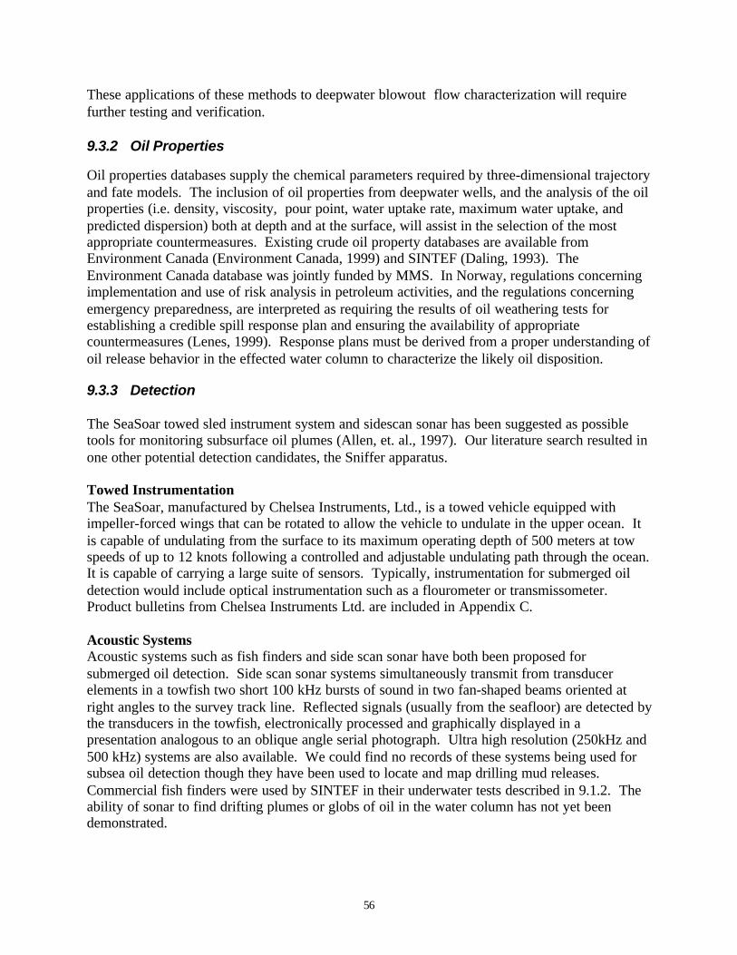
56
These applications of these methods to deepwater blowout flow characterization will requirefurther testing and verification.
9.3.2 Oil Properties
Oil properties databases supply the chemical parameters required by three-dimensional trajectoryand fate models. The inclusion of oil properties from deepwater wells, and the analysis of the oilproperties (i.e. density, viscosity, pour point, water uptake rate, maximum water uptake, andpredicted dispersion) both at depth and at the surface, will assist in the selection of the mostappropriate countermeasures. Existing crude oil property databases are available fromEnvironment Canada (Environment Canada, 1999) and SINTEF (Daling, 1993). TheEnvironment Canada database was jointly funded by MMS. In Norway, regulations concerningimplementation and use of risk analysis in petroleum activities, and the regulations concerningemergency preparedness, are interpreted as requiring the results of oil weathering tests forestablishing a credible spill response plan and ensuring the availability of appropriatecountermeasures (Lenes, 1999). Response plans must be derived from a proper understanding ofoil release behavior in the effected water column to characterize the likely oil disposition.
9.3.3 Detection
The SeaSoar towed sled instrument system and sidescan sonar has been suggested as possibletools for monitoring subsurface oil plumes (Allen, et. al., 1997). Our literature search resulted inone other potential detection candidates, the Sniffer apparatus.
Towed InstrumentationThe SeaSoar, manufactured by Chelsea Instruments, Ltd., is a towed vehicle equipped withimpeller-forced wings that can be rotated to allow the vehicle to undulate in the upper ocean. Itis capable of undulating from the surface to its maximum operating depth of 500 meters at towspeeds of up to 12 knots following a controlled and adjustable undulating path through the ocean.It is capable of carrying a large suite of sensors. Typically, instrumentation for submerged oildetection would include optical instrumentation such as a flourometer or transmissometer.Product bulletins from Chelsea Instruments Ltd. are included in Appendix C.
Acoustic SystemsAcoustic systems such as fish finders and side scan sonar have both been proposed forsubmerged oil detection. Side scan sonar systems simultaneously transmit from transducerelements in a towfish two short 100 kHz bursts of sound in two fan-shaped beams oriented atright angles to the survey track line. Reflected signals (usually from the seafloor) are detected bythe transducers in the towfish, electronically processed and graphically displayed in apresentation analogous to an oblique angle serial photograph. Ultra high resolution (250kHz and500 kHz) systems are also available. We could find no records of these systems being used forsubsea oil detection though they have been used to locate and map drilling mud releases.Commercial fish finders were used by SINTEF in their underwater tests described in 9.1.2. Theability of sonar to find drifting plumes or globs of oil in the water column has not yet beendemonstrated.
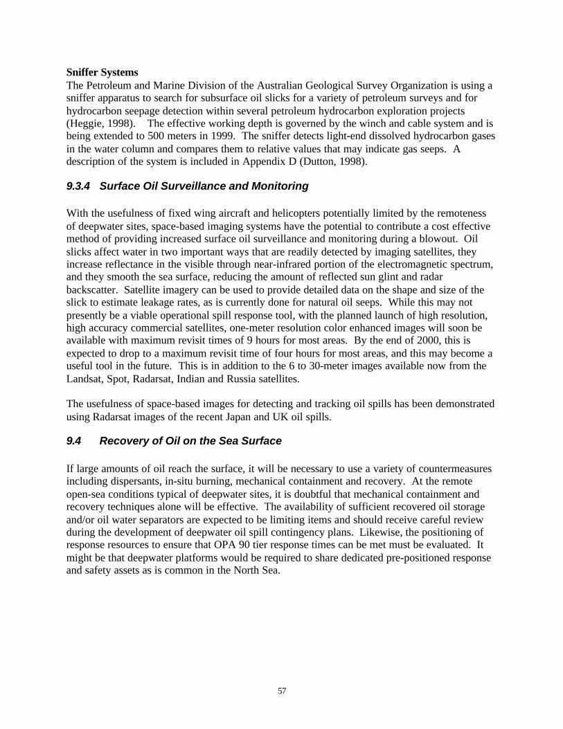
57
Sniffer SystemsThe Petroleum and Marine Division of the Australian Geological Survey Organization is using asniffer apparatus to search for subsurface oil slicks for a variety of petroleum surveys and forhydrocarbon seepage detection within several petroleum hydrocarbon exploration projects(Heggie, 1998). The effective working depth is governed by the winch and cable system and isbeing extended to 500 meters in 1999. The sniffer detects light-end dissolved hydrocarbon gasesin the water column and compares them to relative values that may indicate gas seeps. Adescription of the system is included in Appendix D (Dutton, 1998).
9.3.4 Surface Oil Surveillance and Monitoring
With the usefulness of fixed wing aircraft and helicopters potentially limited by the remotenessof deepwater sites, space-based imaging systems have the potential to contribute a cost effectivemethod of providing increased surface oil surveillance and monitoring during a blowout. Oilslicks affect water in two important ways that are readily detected by imaging satellites, theyincrease reflectance in the visible through near-infrared portion of the electromagnetic spectrum,and they smooth the sea surface, reducing the amount of reflected sun glint and radarbackscatter. Satellite imagery can be used to provide detailed data on the shape and size of theslick to estimate leakage rates, as is currently done for natural oil seeps. While this may notpresently be a viable operational spill response tool, with the planned launch of high resolution,high accuracy commercial satellites, one-meter resolution color enhanced images will soon beavailable with maximum revisit times of 9 hours for most areas. By the end of 2000, this isexpected to drop to a maximum revisit time of four hours for most areas, and this may become auseful tool in the future. This is in addition to the 6 to 30-meter images available now from theLandsat, Spot, Radarsat, Indian and Russia satellites.
The usefulness of space-based images for detecting and tracking oil spills has been demonstratedusing Radarsat images of the recent Japan and UK oil spills.
9.4 Recovery of Oil on the Sea Surface
If large amounts of oil reach the surface, it will be necessary to use a variety of countermeasuresincluding dispersants, in-situ burning, mechanical containment and recovery. At the remoteopen-sea conditions typical of deepwater sites, it is doubtful that mechanical containment andrecovery techniques alone will be effective. The availability of sufficient recovered oil storageand/or oil water separators are expected to be limiting items and should receive careful reviewduring the development of deepwater oil spill contingency plans. Likewise, the positioning ofresponse resources to ensure that OPA 90 tier response times can be met must be evaluated. Itmight be that deepwater platforms would be required to share dedicated pre-positioned responseand safety assets as is common in the North Sea.

58
10.0 Conclusions and Recommendations
10.1 Conclusions
• Leak Point Probabilities: A ranking of potential leak points during drilling, completion andworkover operations indicates that the probability that a deepwater blowout will occur at thewellhead connector, choke and kill stab (LMRP), through the riser, or outside the casing (abroach) is moderate, while the probability that a blowout would occur from other locations islow. For producing wells, the probability that a blowout would occur at the annulus valve ismoderate, while the probability that a blowout would occur from other locations is low.
• Consequences: A consequence analysis of leak points indicates that leaks through thedrillpipe and broaches are catastrophic and will likely result in a sustained blowout, whileleaks from the wellhead connector, through the riser or from the casing seals will have severeconsequences. The relative consequence of leaks from other locations is minor.
• Technical hurdles to be overcome in order to stop an uncontrolled flow of oil from a deep orultra deepwater blowout have been developed and explained in detail in Section 7.
For subsea oil containment the technical hurdles to be overcome during a deepwater blowoutinclude:
• Predicting the behavior of deepwater currents• Ability to manipulate heavy objects on the sea bed• Ability to design subsea collectors that are flexible enough to cap a large range of subsea
wellhead assemblies and accommodate a high volume of recovered oil, gas and water• Ability to approach the blowing well and install containment devices on the seafloor• Lack of standardization in subsea wellhead design
For subsea dispersant application , these include:
• Availability of equipment and methods for delivering the dispersants to the plume
For oil remote sensing and tracking, these include:
• Lack of understanding of plume dynamics• Lack of information on oil properties• Methods for detecting submerged oil plumes• Limited usefulness of surface oil surveillance and monitoring aircraft
For recovery of oil on the sea surface, technical hurdles include:
• Logistical problems for mechanical systems dealing with large quantities of recovered oiland water at locations far offshore

59
• Ability to contain and sustain a safe, controlled burn at remote offshore locations has notbeen demonstrated
10.2 Recommendations
The following technologies and approaches have merit and deserve the opportunity for additionalresearch and development to determine their ability to address the well control, oil tracking andrecovery technical hurdles identified:
• Deepwater Current Measurement: Three systems having the potential to measuredeepwater currents at the blowout site have been identified: a system using ADCPs deployedat different depths, ALACE and APEX floats. Tests of the usefulness of these systemsshould be performed and operational methods developed for the deployment and use of thesystem best suited for use in a deepwater blowout.
• The Multipurpose Deepwater Crawler (MDC2000) concept described in Appendix Boffers a means to assist with the manipulation of heavy objects, delivery of well controltechnologies in ultra-deep waters, and for applying dispersants at the wellhead. This blowoutcountermeasure system can be multifunctional in supporting several different emergency anddeepwater operational situations, and preliminary design development should be pursuedwith this in mind, possibly through a multi-agency design effort.
• Low Priority for Subsea Collection: Recovery of oil from a deepwater blowout is unlikelyfor most subsea releases. The development of subsea collectors and recovery should begiven a low priority until the (1) plume modeling methods are refined and demonstrate thatsignificant oil will reach the surface from a deepwater blowout, and (2) wellhead interventionor dispersant application techniques using subsea systems have already been developed anddemonstrate the need for additional collection and recovery systems.
• Subsea Equipment Standardization: A standardization effort should be undertaken toensure that all subsea equipment designs incorporate standard methods and equipment forwell intervention using standard ROV equipment and tooling.
• Subsea Dispersant Injection Design: Methods, dispersant ratios and injection nozzledesigns should be developed and tested to determine the most effective design for injectionof dispersants directly into a blowout plume. The concept for wellhead independent subseadispersant application should be further developed.
• Predicting Deepwater Blowout Plume Dynamics: The ability to model and predictblowout plume dynamics should be a priority research area, especially the collection of datato validate the predictions.
• Underwater imaging systems should be tested and verified on simulated blowouts todetermine the best system for this application. The best candidates for testing are the highdynamic range CCD camera, the range gate intensified CCD.

60
• Oil properties from deepwater well samples should be analyzed and made available toNOAA and other organizations for inclusion in three-dimensional and fate models.
• Subsurface Oil Plume Detection: Two devices have been identified with the potential todetect subsurface oil plumes: the SeaSoar, and the AGSI Sniffer. Tests of these similardevices should be made during test releases to determine their adequacy for deepwaterapplication, and then the range of the most appropriate system needs to be extended to ultradeepwater. The initial detection tests might be combined with testing of methods to detectsubmerged orimulsion plumes.
• Space Based Imaging Systems: Advances in satellite imaging systems should be monitoredas they offer the potential to contribute a cost effective method of providing increased surfaceoil surveillance and monitoring of remote deepwater sites.
• Surface Spill Countermeasures: The availability of sufficient recovered oil storage and/oroil water separators should be a priority item during the development of deepwater spillresponse plans. Likewise, the positioning of response resources to ensure rapid responsemust be ensured.

61
References
Allen. J.D., C.K. Cooper, T.D. Finnigan and L.A. Young. Deep Water Spill Response:Assessment of Current Knowledge of Spill Behavior, Implications for Removal, andRecommendations for Further Activities. Chevron E&P Department White Paper. September16, 1997.
American Petroleum Institute (API). Recommended Practice (RP) 53. Blowout PreventionEquipment Systems for Drilling Operations. Third Edition. March 1997.
API. Spec 16C. Choke and Kill Systems. First Edition. January 29, 1993.
API. RP 16E. Design of Control Systems for Drilling Well Control Equipment. First Edition.October 1, 1990.
Aundunson, T., O. Johansen, J. Kolnes, and S.E. Sorstrom. “Injection of Oil Spill ChemicalsInto a Blowing Well”. Proceedings of the 1987 Oil Spill Conference. Baltimore, MD. April 6-9,1987. pp 335 - 340.
Brandvik, Per Johan. E-mail from Per Johan Brandvik, SINTEF to Tom Hudon, PCCI, Subj:Underwater blow-out monitoring by ROV/Sonar, 8/24/98.
Brown and Root Development, Inc. Development of an Engineering and Cost Analysis of aShip-Mounted Subsurface Collector System. Final Report. Prepared for MMS under ContractNo. 14-12-0001-30135. December 2, 1985.
Brown, H.M., E.H. Owens and M. Green. “Submerged and Sunken Oil: Behavior, ResponseOptions, Feasibility and Expectations”. Proceedings of the Twenty-First Arctic and MarineOilspill Program(AMOP) Technical Seminar. June 10 to 12, 1998. Edmonton, Alberta, Canada.Volume 1. pp. 135 - 146.
Daling, Per, Ole Morten Aamo, Alun Lewis and Tove Strom-Kristiansen. “SINTEF/IKU OilWeathering Model – Predicting Oil Properties At Sea”. Proceedings. 1997 International OilSpill Conference. Fort Lauderdale, Florida. Paper #455.
Dutton, Steve. E-mail from Steve Dutton, Australian Geological Survey Organization, to T.Hudon, PCCI. 8/26/98.
Environment Canada. A Catalogue of Crude Oil and Oil Product Properties. Copyright 1996-1999. Available at http://www.etcentre.org/spills
Flak, L.H. “Review of Deepwater Blowout Control Methods”. Proceedings of the InternationalDeep Water Well Control Conference. Houston, TX. September 15-16, 1997.
62
Frisbie, Dick. “ROVs and AUVs – New Technology For Ultra Deepwater”, Presentation at theInternational Offshore Contracting and Subsea Engineering Exhibition and Conference (IOCESubsea ’98). Aberdeen, UK. 27-29, October, 1998.
Goldsborough III, Robert G., Ben Allen, Roger Stokey and Dr. Raymond W. Simpson. “High-Resolution Electronic Still Camera”. Sea Technology. February 1998. Pp 65 – 75.
Gould, W.J. Neutrally Buoyant Float Technologies. Web based information athttp://wfdac.whoi.edu/gould.htm. 8/17/98.
Hamilton, Robert C., Michael J. Vogel and Edward K. Noda. “Real-Time Current Profiling InSupport Of The Hawaii Deep Water Cable Program”. 1990 Marine Technology SocietyConference Proceedings. Washington, DC. September 1990.
Heggie, David. E-mail from David Heggie, Australian Geological Survey Organization, to T.Hudon, PCCI. 8/18/98.
Holand, Per. Offshore Blowouts: Causes and Control. Gulf Publishing Company. Houston, TX.1997.
Hvidbak, Flemming. Underwater Remote Detection of Orimulsion Using Sonar. ConfidentialReport prepared for Bitor Corporation. May 31, 1999.
IADC/OOC Deepwater Well Control Task Force. Emergency Response Subcommittee.Deepwater Well Control Guidelines. Part IV Emergency Response Draft. 3/22/98.
International Association of Drilling Contractors. IADC Deepwater Well Control Guidelines.First Edition. October 1998.
Jaffe, Dr. Jules S., Dr. Karl D. Moore, Dave Zawanda, Benjamin L. Ochoa and Dr. EleanoraZege. "Underwater Optical Imaging: New Hardware & Software" . Sea Technology. July1998. Pp 70 – 74.
Lenes, Geir. E-mail from Geir Lenes, SFT, to T. Hudon, PCCI. 1/6/99.
Marine Spill Response Corporation (MSRC). Formation and Breaking of Water-In-OilEmulsions: Workshop Proceedings. Technical Report Series 83-018.
Mather, Angus. Offshore Engineering: An Introduction. Witherby & Company Ltd. 1995.
Neal Adams Firefighters, Inc. “Joint Industry Program for Floating Vessel Blowout Control”.Drilling Engineers Association (DEA)-63. Final Report. 28 December 1991.
Norwegian Petroleum Directorate. Acts, Regulations and Provisions for the Petroleum Activity.1995.
Offshore. “French Group Developing Production Umbilical AUV”. PenWell Publishing.Houston. Americas Edition. Volume 58. Number 10. October 1998. Pp 66 and 158.
63
Reed, Mark, ∅istein Johansen, Henrik Rye, Narve Ekrol, Ivar Singsaas, Per Daling, and PerJohan Brandvik. “Deepwater Blowouts: Modeling for Oil Spill Contingency Planning,Monitoring, and Response”. Proceedings of the 1999 International Oil Spill Conference.Seattle, WA. API Publication No. 4686.
Rye, Henrik, and Per Johan Brandvik. “Verification of Subsurface Oil Spill Models”.Proceedings of the 1997 International Oil Spill Conference. Fort Lauderdale, FL. April 7-10,1997.
Shell. Information form the Shell Exploration and Production Company web page athttp://www.shellus.com/sepco/ on 11/3/98.
Simpson, Raymond W. E-mail from Dr. Simpson, Roper Scientific Trenton, to T. Hudon, PCCI,RE: Use of CCD Cameras for oil well blowout observation. 10/2/98.
Spaulding, Malcolm L. “A Model for Subsea Deepwater Blowouts”. Undated White Paper.Forwarded by Eric Anderson, ASA, in an E-mail dated 7/31/98.
Stewart Technology Associates. “Development of an Engineering and cost Analysis of a Ship-Mounted Surface Collector System”. November 1987.
Topham, D.R. “Hydrodynamics of an Oilwell Blowout”. Beaufort Sea Technical Report #33.Department of the Environment, Victoria, Canada. 1975.
University of Hawaii. “Experimental Study of Multi-Phase Plumes with Applications to DeepOcean Oil Spills”. Technical Proposal submitted to Minerals Management Service. Revised 25May 1998.
Uzzell, Jesse, and Aage Bjorn Andersen. “A Response Plan for Deep Sea Blowouts in the NorthSea: Monitoring the Subsea Plume”. Proceedings. 1999 International Oil Spill Conference.Seattle, Washington. Paper #110. American Petroleum Institute Publication No. 4686 A (CD-ROM) or 4686 B (bound copy).
Webb, Dan. Telephone conversation between Dan Webb, Webb Research Corporation, and T.Hudon, PCCI. 8/18/98.
Westergaard, Rich H. All About Blowout. Norwegian Oil Review Ltd. Oslo, Norway. 1987.
Zheng, Li and Poojitha D. Yapa. “A Deepwater Jet/Plume Model and A Parametric Analysis”.Proceedings of the Twenty Second Arctic and Marine Oilspill Program (AMOP) TechnicalSeminar. Calgary, Alberta, Canada. June 2 to 4, 1999.
64
GLOSSARY
This glossary is a guide for spill planning professionals and other readers who are not familiarwith offshore well control operations. Most of the terms are from Holand, 1997 and Mather,1995.
ANNULAR BOP (BLOWOUT PREVENTER): A device with a generally toroidalshaped steel-reinforced elastomer element that is hydraulically operated to close and sealaround any drill pipe size (or other tubular) to provide full closure packing of thewellbore.
ANNULUS: The space surrounding any tubular suspended in the hole. During drillingthe circulation fluid flows up the annulus between the drillpipe and the wall of the hole,or, when the well is cased, between the drillpipe and the casing.
BLIND RAM BOP (BLOWOUT PREVENTER): A BOP having rams which sealagainst each other to close the well bore in the absence of any pipe.
BLOWOUT: A blowout is an uncontrolled flow of formation fluids from a wellbore.
BLOWOUT PREVENTER: A device to control formation pressures in a well bysealing the annulus around the drillpipe (or tubular) when it is suspended in the hole, oralternatively by sealing across the entire hole if no pipe is in it. Blind/Shear Rams havecutting blades that will shear tubulars that may be in the wellbore, while the rams closeand seal against the pressure below. Different types of preventers are assembled in ablowout preventer (BOP) stack.
BRIDGE (DOWNHOLE): An obstruction in the hole usually caused by the wall of thehole caving in. This may be caused by formation collapse, which is considered“passive”, or may be induced, which is called “active”.
CASING: Steel pipe set in the hole as drilling progresses to line the hole wall,preventing caving-in and providing a passage to the surface for drilling fluid and forhydrocarbons if the well is proved productive.
CHOKE: A valve like device with a fixed or variable aperture specifically intended toregulate the flow of fluids.
CHRISTMAS TREE: A high pressure assembly of valves, pipes, and fittings installedon a wellhead after completion of drilling to control the flow of oil and gas from thecasing.
CONDUCTOR: The first, and largest diameter pipe to be inserted or drilled into theseabed when drilling a well. It keeps the hole open, provides a return passage for thedrilling mud and supports the subsequent casing strings.
65
DIVERTER: A piping arrangement attached to the top of the marine riser that closesthe vertical passage and directs the flow of well fluids away from the rig floor andoverside.
FLOWLINE: Piping which directs well fluids from the wellbore to the surfaceequipment.
INFLUX: An unexpected flow of formation fluids into the wellbore.
KICK: See INFLUX
KILL LINE: A high pressure line attached to the BOP stack through which heavydrilling fluid can be pumped into the hole to kill a well. On a semisubmersible or a drillship the kill line runs down the side of the marine riser.
LOWER MARINE RISER PACKAGE (LMRP): An assembly comprised of the flexor ball joint, an annular blowout preventer, hydraulic accumulators, sections of riser andthe riser slip joint, all of which can be detached from the rest of the BOP stack in anemergency to allow the drilling unit to move off location whilst leaving the well secure.
MARINE RISER: The large-diameter pipe connecting the BOP stack to the slip joint ofa semisubmersible or drill ship through which the drillstring passes to the well andthrough which returns of drilling fluid pass from the well to the rig.
MUD: Liquid drilling fluid circulated down the hole and back to the rig.
PACKER: Mechanical or wireline device placed in the hole as a temporary device forsealing one casing string from another, or from the production tubing. Different designsare made for a variety of uses.
PRODUCTION TUBING: Pipe used in wells to conduct fluid from the producingformation into the Christmas tree. Unlike the casing the tubing is designed to be replacedduring the life of the well, if required.
ROTARY TABLE: The housing for the mechanism in the center of the drill floor thatdrives the kelly and turns the drillstring and bit. All downhole tools, casing, etc. are runthrough its opening.
SLIP JOINT: A telescopic joint inserted near the top of the marine riser to absorb thevertical heaving motion of the drilling unit when in a seaway.
SURFACE CONTROLLED SUBSURFACE SAFETY VALVE (SCSSV): A SCSSVis located in the production tubing subsurface. The valve can be used for closing in awell if a topside situation occurs that disables the Christmas tree valves. The valve iscontrolled from the surface. These valves are frequently referred to as DHSVs (DownHole Safety Valves). A DHSV does, however, not have to be surfaced controlled; it canbe flow controlled. The flow controlled valves are frequently referred to as storm chokes.

66
TRIPPING: The operation of pulling the drillstring out of the well or running thedrillstring into the well.
WELL COMPLETION: The final phase of operations after total depth has beenreached (e.g., when the well is fitted with production equipment).
WELLHEAD: Permanent equipment used to secure and seal the casing strings andproduction tubing and to provide a mounting place for the Christmas trees.
WORKOVER: An operation in which a rig is employed to restore or improveproduction from a completed well.

Created on 11/4/98 at 11:30 A-1
Appendix A – Data Sheets for ALACE and APEX Floats

Created on 11/4/98 at 11:30 B-1
Appendix B - The Multipurpose Deepwater Crawler (MDC 2000)
Concept Design
B.1 Introduction
The Multipurpose Deepwater Crawler (MDC) concept evolved as a potential solution to thetechnical hurdles identified in Section 7, i.e. the deepwater currents, ability to manipulate heavyobjects, provide subsea power, ability to approach the blowout plume, and provide wellheadintervention or inject dispersants into the plume.
B.2 Background
Based upon the technical hurdles identified in Section 7.0 of the report, and knowledge of ROVtechnology, the team identified a number of critical design points for the MDC concept.
• A major reason that none of the earlier blowout response concepts have been developed isthe high capital cost for equipment dedicated solely for an operation that has a smallprobability of occurrence. This means that the equipment should not be dedicated only fordeep water blow out operations. It should also be able to perform other subsea or land basedtasks. This is important when considering life time costs. The MDC should be multipurpose.
• The MDC should be able to perform oil well blowout intervention tasks as follows:
Monitor and evaluate the situation around the oil wellCut debrisConnect wires for heavy surface assisted liftsCut and cap pipes for access to the kill and choke linesAttach well killing fluid linesProvide hydraulic power as a backup for BOP control systemsInject dispersant.
B.3 General Description
The MDC concept that is not a free swimming unit. It operates from the sea bed and uses the seafloor as an operational platform. The vehicle itself is equipped with tractor belts and moves as aconventional tractor. The vehicle will act as a platform for a hydraulic arm with a reach of 40 to45 ft and several six degree-of-freedom manipulators. During operation of the arm the vehiclewill secure itself to the seafloor by hydraulic operated screw piles. The unit is powered andcontrolled from a subsea platform which is installed by a crane vessel in a conventional way. Allcritical components such as electro hydraulic powerpack, junction boxes and control system arefixed to the platform. The vehicle gets hydraulic supply from the platform through an umbilicalcontaining hydraulic lines as well as signal lines for operating solenoid valves and transferringdata from the onboard surveillance system. The long reach hydraulic arm can be equipped with

Created on 11/4/98 at 11:30 B-2
all available ROV tools such as cutters, saws, grinders etc. In addition the arms will be able tocarry a tool for dispersant injection into the jet zone of the blowout plume.
The MDC should also be able to operate on land. This means that the vehicle is build for ultradeep water but is powerful enough to operate on land. During subsea operation, additionalweight is added to the vehicle. Since the vehicle itself is intrinsically safe it will be able tooperate in hazardous areas on land such as in mines, ship tanks, etc.
B.4 Equipment Description
The MDC would be comprised of three main elements as shown in Figure B-1 and described inthe following sections:• base template,
• control platform
• vehicle
B.4.1 Base Template
The main function of the base template will be to provide a structural support base for the controlplatform and lock it to the sea floor. It is equipped with four hydraulic operated screw piles andis lowered to the sea floor by proven methods. During installation to the sea floor, guide wireswill be established to the surface. The guide wires will guide the control platform onto guideposts located on the base template.
B.4.2 Control Platform
The control platform is a separate unit containing the MDC, a hydraulic operated umbilicaldrum, pressure vessel with the control system, pressure vessel with the transformer and junctionbox, and the electro hydraulic power pack. Electric power has to be supplied from the surface.Due to the long distance, a high voltage system should be used. Vehicle, manipulator and opticalequipment control should occur via fiber optics in order to prevent signal interference from thehigh voltage system.
The control system will have to operate at surface pressure and will need to be located inside apressure vessel with sub sea connectors rated for ultra deep water. This system is similar to thoseused on ROVs designed for ultra deep water.
The hydraulic system will be pressure balanced and will work independent of the water depth.However, special emphasis must be put on the design in order to avoid air or gas bubbles in thesystem.
B.4.3 Multipurpose Deepwater Crawler Vehicle
The MDC vehicle will be of a conventional type as presently used for subsea pipeline and cabletrenching. It is hydraulic operated and the power is taken from the electro hydraulic power packon the control platform. The power is supplied via an umbilical (See Figure B-2) from the

Created on 11/4/98 at 11:30 B-3
hydraulic operated umbilical drum. The controls onboard the crawler should be of a conventionaltype and all functions are initiated from the control system in the pressure vessel located on thecontrol platform.
The hydraulic operated combined crane and manipulator arm will have to be specially designedfor the vehicle. It needs to have a long reach and at the same time it needs to fold back in order tobe accommodated on the MDC and the control platform. A second, shorter manipulator arm isdesirable to assist with positioning of imaging systems (as described in Section 9.3.1 of thereport) or other tools. Weight will be added to the unit in order for it to be stable on the sea floorin heavy current. The tractor drive will be of the same type as that used on land based mini-tractors. It should be sturdy, powerful and hydraulic operated.
During operation of the long manipulator arm, the MDC will have to be supported by hydraulicoperated telescopic support pods. The unit should also be equipped with screw type piles in orderto lock itself to the seabed during operation in unconsolidated sediments.
B.5 Equipment Operation
Deepwater and ultra deepwater blowouts are expected to be rare. Therefore, the MDC has beendesigned to be multifunctional and capable for use on a number of tasks including operation indeep and ultra deep waters to deliver blowout countermeasures, use in shallower depths toperform routine subsea operations, surf zone delivery of offload hoses, and surface operationsinvolving hazardous materials.
B.5.1 Blowout Countermeasure Operations In Deep and Ultra Deep Waters
The MDC is designed for operation in water depths beyond 6500 ft. and all proposed proceduresare based upon proven methods.
Installation
The base template can be installed from the surface by a dynamically positioned crane vessel.The template is lowered to the seabed and is equipped with transponders and/or an inertianavigational system ( noise from the blowing well may disturb the transponder signal ).During launch, the guide wire connection is established to the surface.
The control platform containing the MDC is lowered onto the template via these guide wires. Byhaving a fixed template on the seabed the control platform can be retrieved at any time forservice or repair while maintaining connection to the seafloor near the blowout.
The control platform will enter the guideposts on the template and lock itself to the template.A landing ramp will be lowered and the MDC can leave the control platform.
See Figures B-3.1 and B-3.2.
Created on 11/4/98 at 11:30 B-4
Operation
The MDC will be dependant upon a reliable navigational system as well as a system fororientation in a dark, possibly sediment filled environment. It is expected that the poor visibilitywill be one of the most challenging parts in the design of the MDC. The vehicle is operated fromthe surface, where all controls are located. Both vehicle movements and arm manipulation willbe carried out by a pilot onboard the surface vessel.
The first objective for the MDC, once in place, is to supply information to the surface about:current velocity and direction, conditions around the blowing well, and to obtain an image of theblowing well.
Depending upon the operation, the MDC will be able to retrieve tools from a cassette located onthe vehicle. The cassette tool system will need to be developed as part of the next (feasibility)design effort and should consider the other operations outlined in Section B.5.2.
If dispersant application is required, dispersant will have to be supplied from the surface via aseparate hose to the control platform or to the MDC itself. Alternative methods have to beevaluated depending upon the amount of dispersant needed. The MDC will be equipped withhigh pressure spray nozzles in the end of the manipulator arm. It might also be possible,depending upon the situation, for the MDC to make a hose connection to the kill and choke linefor direct injection of dispersant to the oil well.
See the concept for subsea blowout countermeasure operations in Figure B-4.
B.5.2 Other Subsea Operations
The MDC is a multipurpose tool which can be used in a number of subsea applications. If theMDC is operated in water depths above approximately 300 feet, the base template and controlplatforms as previously described, may not be needed. Hydraulic power could then be supplieddirectly from the surface.
Subsea Clean-up Operations
The MDC can be used for subsea removal of hazardous materials like PCBs, chemicals andsunken oil located on the sea floor. The unit can then be equipped with a dredge suction headcombined with a rotating seabed cutter attached to the manipulator arm. Suction can be takenfrom any system that creates underpressure, but one solution is to take the suction from a waterpump driven ejector system located either on the seafloor, onboard an operating vessel or on thecontrol platform. See Figure B-5.
Subsea Inspection
The MDC should also be useful for inspection and repair operations on subsea pipes and cables.Since the unit is fixed to the seabed, thrusters, as used on conventional ROVs, will not stir up thesediments and thus limit the visibility. See Figure B-6.
Created on 11/4/98 at 11:30 B-5
Subsea Cable Laying
The MDC will be able to perform cable laying operations. The unit can be equipped with a trailercontaining pumps and a water jet sword used for cutting into the seabed. The arm of the MDCcould be used to guide the cable between the tractor belts and into the cable laying trailer. Seefigure B-7. Such systems have been used in Scandinavia.
B.5.3 Surf Zone Operation
The MDC would have been a useful tool for the recent container ship groundings and associatedoil spills that occurred offshore Alaska (M/V Kuroshima) and Oregon (M/V New Carissa). TheMDC could have been used to efficiently deliver the floating hose offload system to the strandedtankers by drving the hose into the surf and lifting it up to the tanker using the long manipulatorarm.
B.5.4 Surface Operation
The MDC could be designed for surface operation as well as subsea operation. This would makethe system truly multipurpose. The design itself will give the MDC some unique features as aland operated robot, as the subsurface design will be intrinsically safe. No electric componentsare used in the power system and the solenoid valves for operation of the hydraulic system willbe installed inside a pressure balanced oil reservoir. A separate control system will be used forthe surface operation. The template and the control platform are not needed for such operation.During land based operation the MDC will be lighter than operated subsea, extra weight is onlyadded to the unit in a subsurface mode.
Operation in Enclosed Gas Dangerous Areas
The MDC with its long reach manipulator arm will be a possible asset for working in enclosedareas where there is a danger of explosion. It can basically perform the same functions as in thesubsurface mode. Power can be taken directly from a diesel hydraulic power pack locatedoutside the gas zone. See Figure B-8.
Mine Hunting and Mine Demolition
The long reach arm can be equipped with mine detection devices and the tractor belts will ensurethat the vehicle will be able to move in the terrain. The reach for the mine detection equipmentwill have a radius of 45ft. By equipping the arm with a steel rotating drum the unit may be usedto set off possible mines. See Figure B-9.
Investigation and Removal of Hazardous Material
The MDC will with its long reach arm be ideal for investigation of hazardous material as well asremoval of such material. See Figure B-10.

Created on 11/4/98 at 11:30 B-6
B.6 Costs
System equipment and operational costs will be determined during the follow-on preliminarydesign phase. We estimate design costs to be on the order of $500,000 and vehicle constructioncosts to be on the order of $2,500,000.