OIL & GAS - afengineering.jpafengineering.jp/download/FP-3.pdf · The purpose of a 3 phase...
24
OIL & GAS SEPARATOR INTERNALS
-
Upload
nguyenxuyen -
Category
Documents
-
view
218 -
download
0
Transcript of OIL & GAS - afengineering.jpafengineering.jp/download/FP-3.pdf · The purpose of a 3 phase...
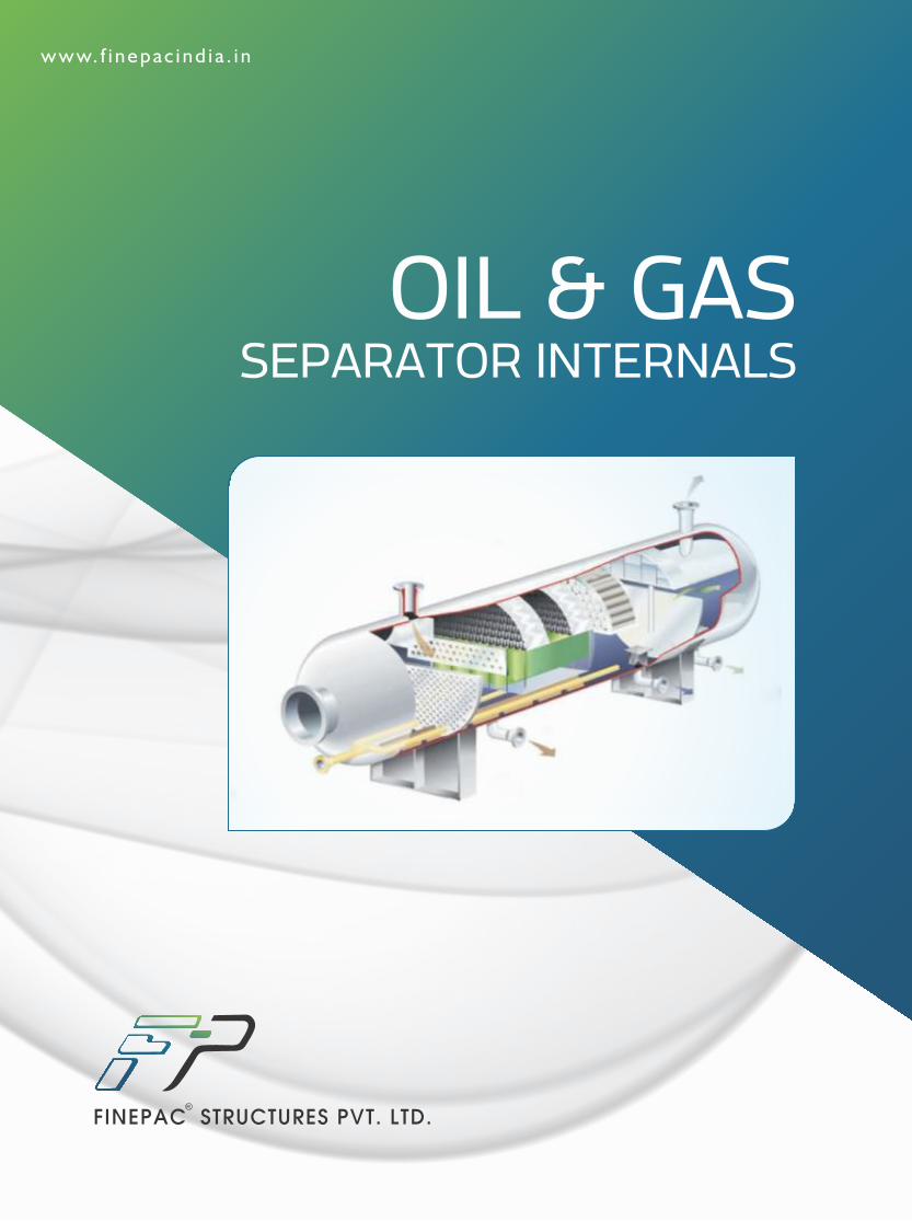
OIL & GAS SEPARATOR INTERNALS
In any industrial process there are many instances where free liquids and solids come in contact with
gases. These free liquids and solids cause a number of undersirable effects within any process and they
need to be eliminated from the gas flow as soon as possible for technical as well as economic reasons.
Free liquid droplets, droplet clusters and liquid slugs are generated through various mechanisms which
are either forced or occur naturally. These liquids which get carried along with the gaseous phase may
cause a number of problems like loss of product, equipment damage, process inefficiency etc. and must be
separated quickly.
Finepac Structures in association with Kirk Process Solutions (UK) offers a full range of specialist
internals, design services and software support for your engineering and procurement activities, vessel
sizing and optimization, process performance prediction and internals selection. Our expertise in
separation is evidenced by hundreds of operational vessels installed worldwide including a number of
state of the art separation technologies and their design.
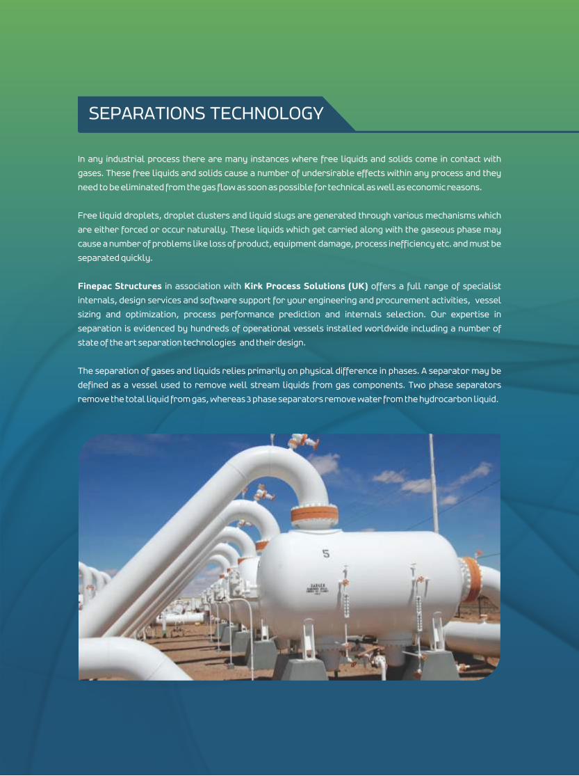
The separation of gases and liquids relies primarily on physical difference in phases. A separator may be
defined as a vessel used to remove well stream liquids from gas components. Two phase separators
remove the total liquid from gas, whereas 3 phase separators remove water from the hydrocarbon liquid.
SEPARATIONS TECHNOLOGY
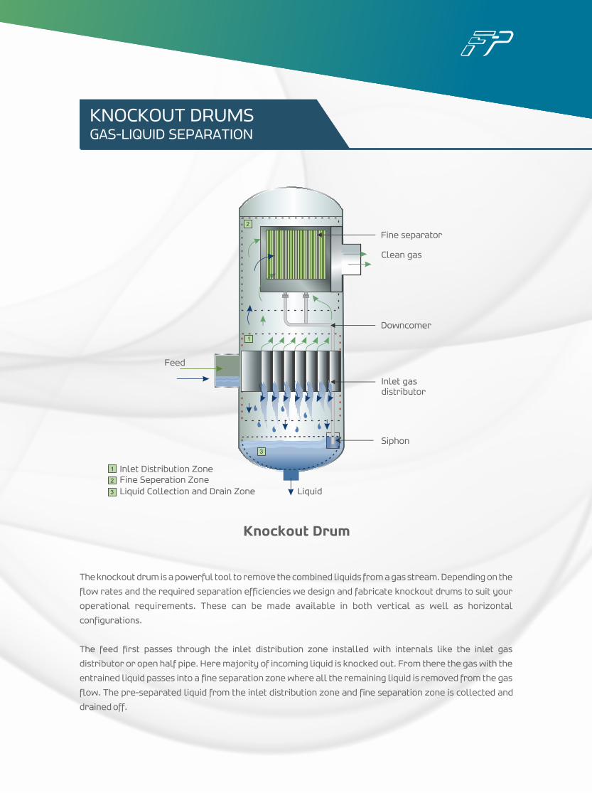
The knockout drum is a powerful tool to remove the combined liquids from a gas stream. Depending on the
flow rates and the required separation efficiencies we design and fabricate knockout drums to suit your
operational requirements. These can be made available in both vertical as well as horizontal
configurations.
The feed first passes through the inlet distribution zone installed with internals like the inlet gas
distributor or open half pipe. Here majority of incoming liquid is knocked out. From there the gas with the
entrained liquid passes into a fine separation zone where all the remaining liquid is removed from the gas
flow. The pre-separated liquid from the inlet distribution zone and fine separation zone is collected and
drained off.
2
1
3
Feed
Liquid
Siphon
Inlet gasdistributor
Downcomer
Clean gas
Fine separator
1
2
3
Inlet Distribution ZoneFine Seperation ZoneLiquid Collection and Drain Zone
KNOCKOUT DRUMSGAS-LIQUID SEPARATION
Knockout Drum
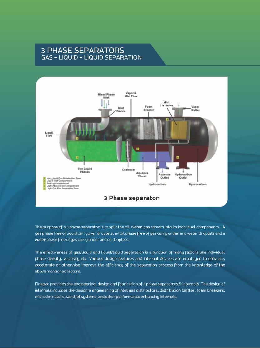
The purpose of a 3 phase separator is to split the oil-water-gas stream into its individual components – A
gas phase free of liquid carryover droplets, an oil phase free of gas carry under and water droplets and a
water phase free of gas carry under and oil droplets.
The effectiveness of gas/liquid and liquid/liquid separation is a function of many factors like individual
phase density, viscosity etc. Various design features and internal devices are employed to enhance,
accelerate or otherwise improve the efficiency of the separation process from the knowledge of the
above mentioned factors.
Finepac provides the engineering, design and fabrication of 3 phase separators & internals. The design of
internals includes the design & engineering of inlet gas distributors, distribution baffles, foam breakers,
mist eliminators, sand jet systems and other performance enhancing internals.
3 PHASE SEPARATORSGAS – LIQUID – LIQUID SEPARATION
3 Phase seperator
Mist Eliminator
Phase
Finepac provides the process guarantee for the following
Removal efficiency of liquid droplets in gas stream
Maximum liquid content in the outlet gas stream
Maximum content of water in the oil phase
Maximum level of hydrocarbon liquid in the water outlet flow.
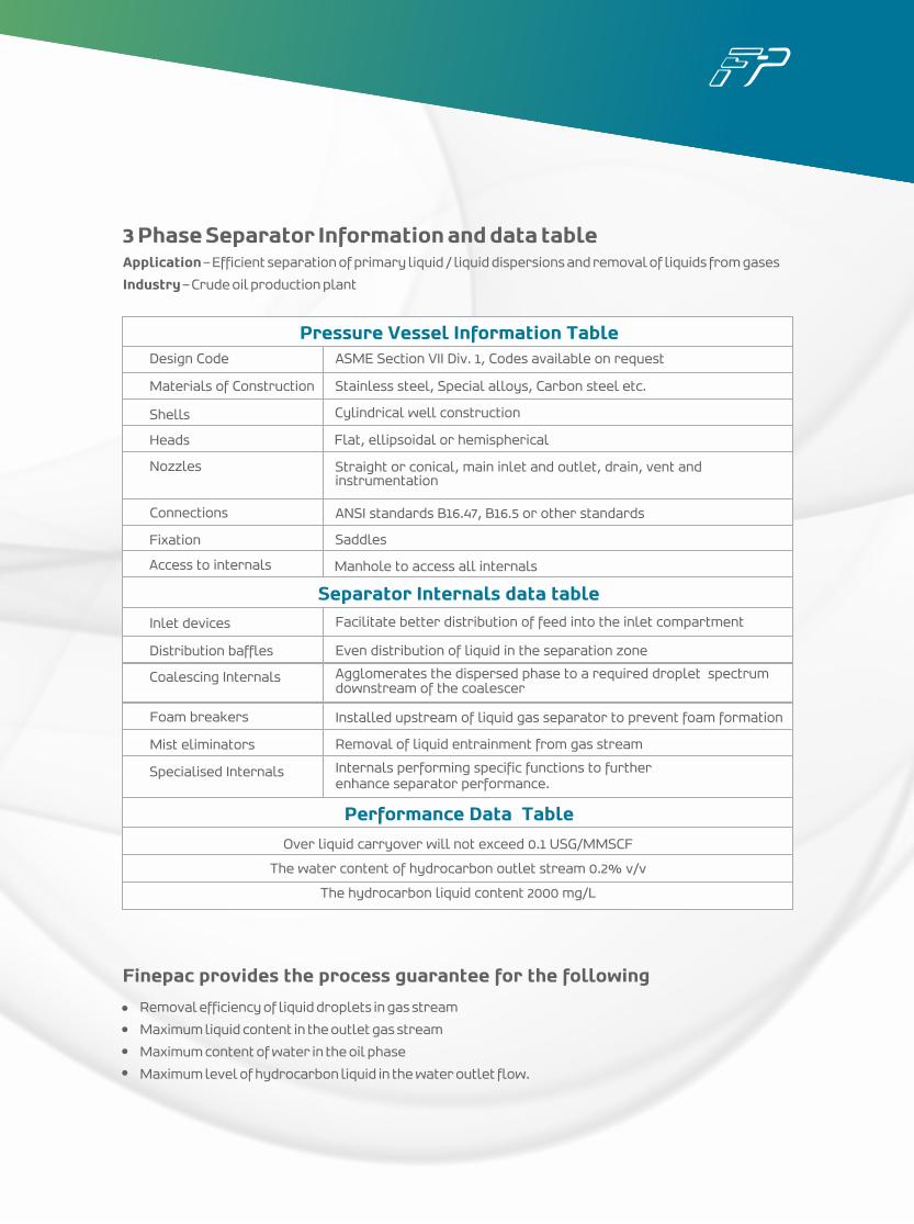
Pressure Vessel Information Table
Shells
Heads
Nozzles
Connections
Fixation
Access to internals
Cylindrical well construction
Flat, ellipsoidal or hemispherical
Straight or conical, main inlet and outlet, drain, vent and instrumentation
ANSI standards B16.47, B16.5 or other standards
Saddles
Manhole to access all internals
Separator Internals data table
Inlet devices
Distribution baffles
Coalescing Internals
Foam breakers
Mist eliminators
Specialised Internals
Facilitate better distribution of feed into the inlet compartment
Even distribution of liquid in the separation zone
Agglomerates the dispersed phase to a required droplet spectrum downstream of the coalescer
Installed upstream of liquid gas separator to prevent foam formation
Removal of liquid entrainment from gas stream
Internals performing specific functions to further enhance separator performance.
Performance Data Table
Over liquid carryover will not exceed 0.1 USG/MMSCF
The water content of hydrocarbon outlet stream 0.2% v/v
The hydrocarbon liquid content 2000 mg/L
Design Code
Materials of Construction
ASME Section VII Div. 1, Codes available on request
Stainless steel, Special alloys, Carbon steel etc.
3 Phase Separator Information and data table Application – Efficient separation of primary liquid / liquid dispersions and removal of liquids from gases
Industry – Crude oil production plant
For a high efficiency separation performance
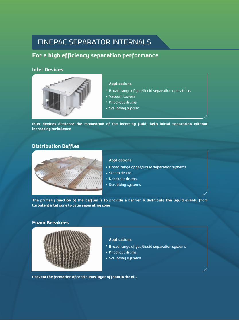
Inlet devices dissipate the momentum of the incoming fluid, help initial separation without increasing turbulence
Inlet Devices
Applications
Broad range of gas/liquid separation operations
Vacuum towers
Knockout drums
Scrubbing system
The primary function of the baffles is to provide a barrier & distribute the liquid evenly from turbulent inlet zone to calm separating zone
Distribution Baffles
Applications
Broad range of gas/liquid separation systems
Steam drums
Knockout drums
Scrubbing systems
Prevent the formation of continuous layer of foam in the oil.
Foam Breakers
Applications
Broad range of gas/liquid separation systems
Knockout drums
Scrubbing systems
FINEPAC SEPARATOR INTERNALS
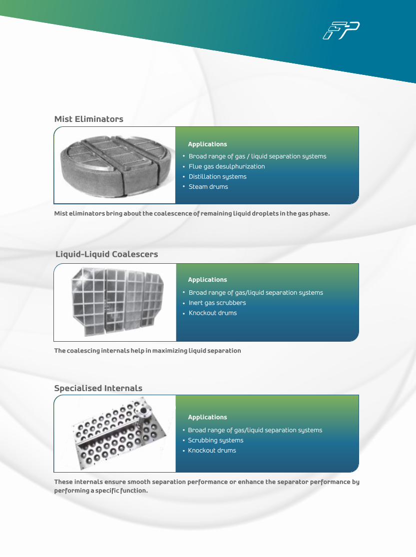
These internals ensure smooth separation performance or enhance the separator performance by performing a specific function.
Specialised Internals
Liquid-Liquid Coalescers
The coalescing internals help in maximizing liquid separation
Applications
Broad range of gas/liquid separation systems
Inert gas scrubbers
Knockout drums
Mist eliminators bring about the coalescence of remaining liquid droplets in the gas phase.
Mist Eliminators
Broad range of gas/liquid separation systems
Scrubbing systems
Knockout drums
Applications
Broad range of gas / liquid separation systems
Flue gas desulphurization
Distillation systems
Steam drums
Applications
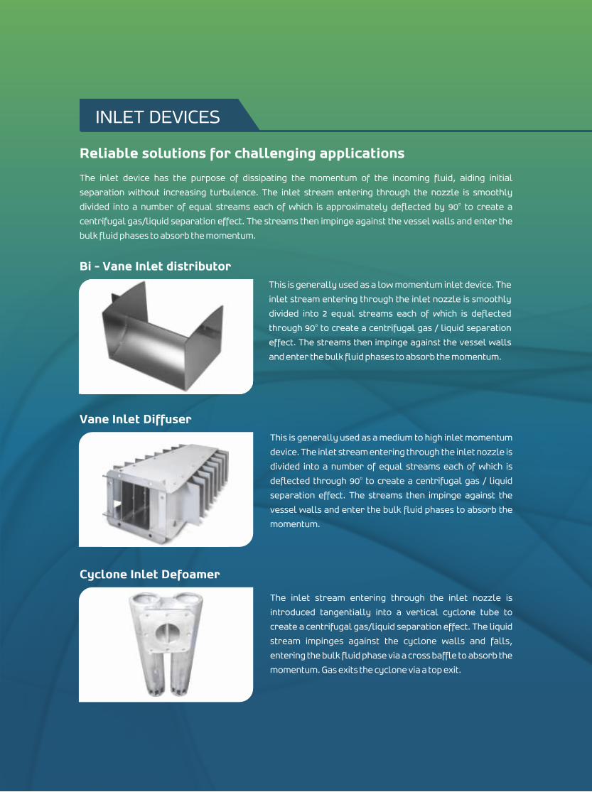
The inlet device has the purpose of dissipating the momentum of the incoming fluid, aiding initial
separation without increasing turbulence. The inlet stream entering through the nozzle is smoothly odivided into a number of equal streams each of which is approximately deflected by 90 to create a
centrifugal gas/liquid separation effect. The streams then impinge against the vessel walls and enter the
bulk fluid phases to absorb the momentum.
Bi - Vane Inlet distributorThis is generally used as a low momentum inlet device. The
inlet stream entering through the inlet nozzle is smoothly
divided into 2 equal streams each of which is deflected othrough 90 to create a centrifugal gas / liquid separation
effect. The streams then impinge against the vessel walls
and enter the bulk fluid phases to absorb the momentum.
Vane Inlet DiffuserThis is generally used as a medium to high inlet momentum
device. The inlet stream entering through the inlet nozzle is
divided into a number of equal streams each of which is odeflected through 90 to create a centrifugal gas / liquid
separation effect. The streams then impinge against the
vessel walls and enter the bulk fluid phases to absorb the
momentum.
Cyclone Inlet Defoamer
The inlet stream entering through the inlet nozzle is
introduced tangentially into a vertical cyclone tube to
create a centrifugal gas/liquid separation effect. The liquid
stream impinges against the cyclone walls and falls,
entering the bulk fluid phase via a cross baffle to absorb the
momentum. Gas exits the cyclone via a top exit.
INLET DEVICES
Reliable solutions for challenging applications
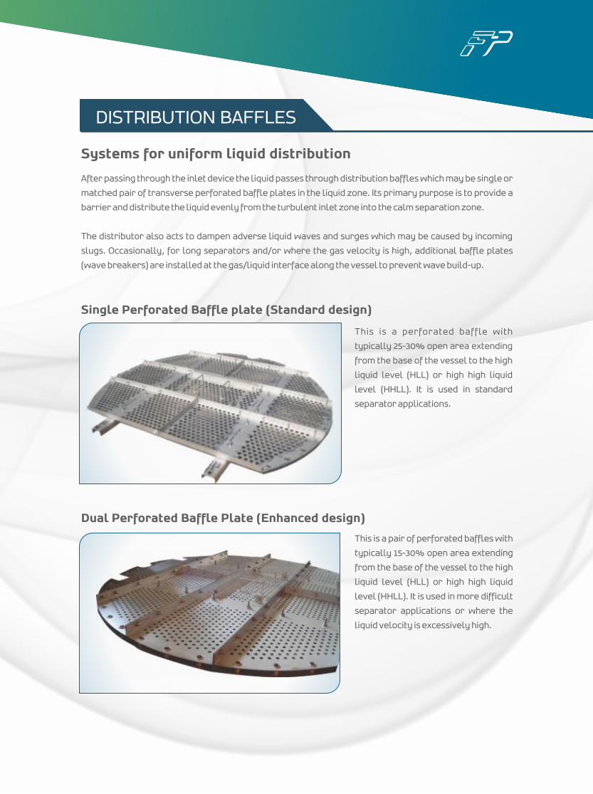
After passing through the inlet device the liquid passes through distribution baffles which may be single or
matched pair of transverse perforated baffle plates in the liquid zone. Its primary purpose is to provide a
barrier and distribute the liquid evenly from the turbulent inlet zone into the calm separation zone.
The distributor also acts to dampen adverse liquid waves and surges which may be caused by incoming
slugs. Occasionally, for long separators and/or where the gas velocity is high, additional baffle plates
(wave breakers) are installed at the gas/liquid interface along the vessel to prevent wave build-up.
Single Perforated Baffle plate (Standard design)
This is a perforated baffle with
typically 25-30% open area extending
from the base of the vessel to the high
liquid level (HLL) or high high liquid
level (HHLL). It is used in standard
separator applications.
Dual Perforated Baffle Plate (Enhanced design)
This is a pair of perforated baffles with
typically 15-30% open area extending
from the base of the vessel to the high
liquid level (HLL) or high high liquid
level (HHLL). It is used in more difficult
separator applications or where the
liquid velocity is excessively high.
DISTRIBUTION BAFFLES
Systems for uniform liquid distribution
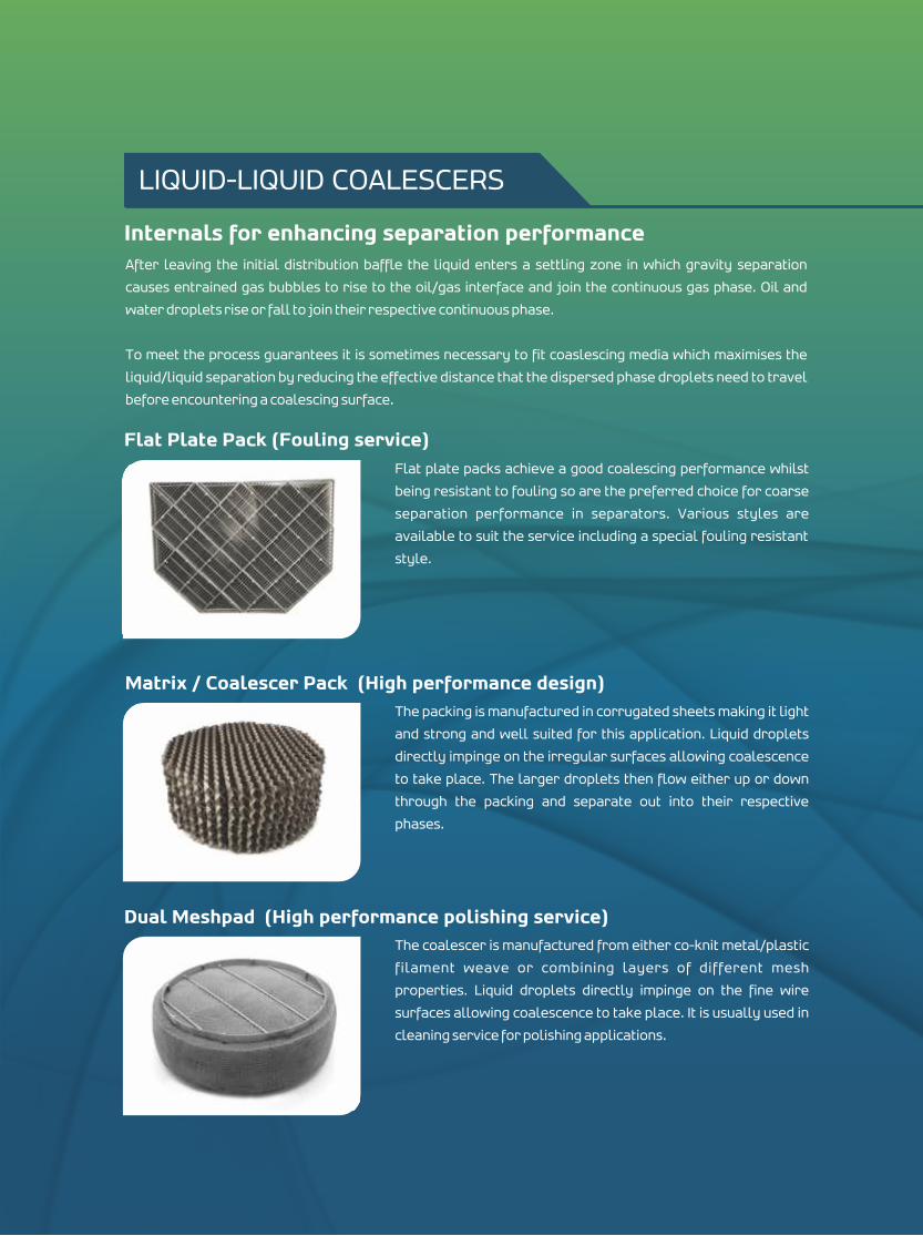
After leaving the initial distribution baffle the liquid enters a settling zone in which gravity separation
causes entrained gas bubbles to rise to the oil/gas interface and join the continuous gas phase. Oil and
water droplets rise or fall to join their respective continuous phase.
To meet the process guarantees it is sometimes necessary to fit coaslescing media which maximises the
liquid/liquid separation by reducing the effective distance that the dispersed phase droplets need to travel
before encountering a coalescing surface.
Flat Plate Pack (Fouling service)Flat plate packs achieve a good coalescing performance whilst
being resistant to fouling so are the preferred choice for coarse
separation performance in separators. Various styles are
available to suit the service including a special fouling resistant
style.
Matrix / Coalescer Pack (High performance design)The packing is manufactured in corrugated sheets making it light
and strong and well suited for this application. Liquid droplets
directly impinge on the irregular surfaces allowing coalescence
to take place. The larger droplets then flow either up or down
through the packing and separate out into their respective
phases.
Dual Meshpad (High performance polishing service)The coalescer is manufactured from either co-knit metal/plastic
filament weave or combining layers of different mesh
properties. Liquid droplets directly impinge on the fine wire
surfaces allowing coalescence to take place. It is usually used in
cleaning service for polishing applications.
LIQUID-LIQUID COALESCERS
Internals for enhancing separation performance
Over the years considerable effort has been taken on the development of sand or sludge removal
systems. However, no single Sand – Jet system has evolved as clearly superior. Rather, there are a
number of design features to choose from depending upon the application requirement. Finepac provides
Sand Jet systems based on a wide range of features to provide the perfect solution for the application in
the most economic way.
A sand jet pipe system can be fitted along the bottom of the vessel running up to a sand retention baffle or
a weir plate. High pressure water will fluidise any solids settled in the base of the vessel so they can be
flushed away into the sand removal nozzles. A sand pan to prevent clogging and blockage is also usually
supplied.
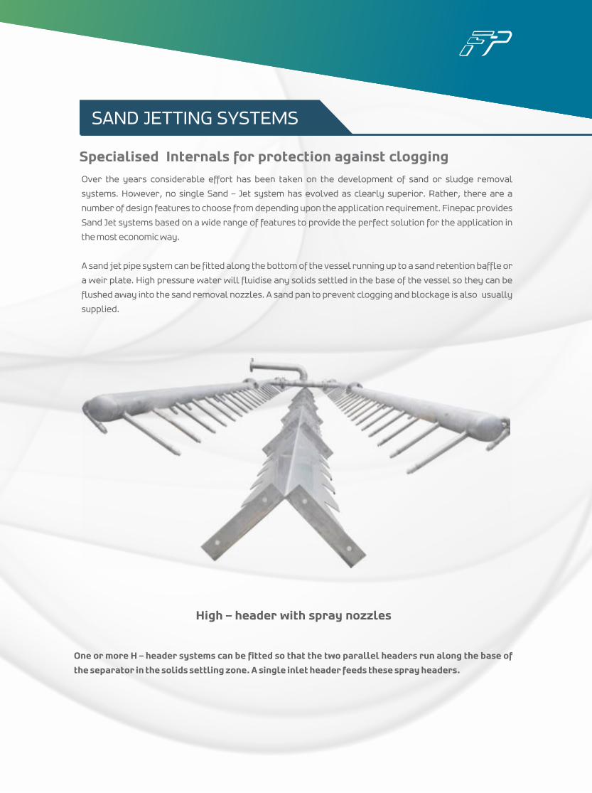
High – header with spray nozzles
One or more H – header systems can be fitted so that the two parallel headers run along the base of
the separator in the solids settling zone. A single inlet header feeds these spray headers.
SAND JETTING SYSTEMS
Specialised Internals for protection against clogging
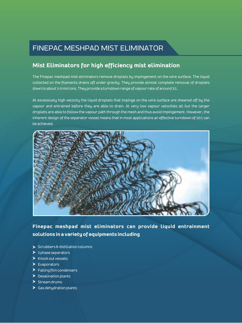
Mist Eliminators for high efficiency mist elimination
The Finepac meshpad mist eliminators remove droplets by impingement on the wire surface. The liquid
collected on the filaments drains off under gravity. They provide almost complete removal of droplets
down to about 3-5 microns. They provide a turndown range of vapour rate of around 3:1.
At excessively high velocity the liquid droplets that impinge on the wire surface are sheared off by the
vapour and entrained before they are able to drain. At very low vapour velocities all but the larger
droplets are able to follow the vapour path through the mesh and thus avoid impingement. However, the
inherent design of the separator vessel means that in most applications an effective turndown of 10:1 can
be achieved.
Finepac meshpad mist eliminators can provide liquid entrainment
solutions in a variety of equipments including
Scrubbers & distillation columns
3 phase separators
Knock out vessels
Evaporators
Falling film condensers
Desalination plants
Stream drums
Gas dehydration plants
FINEPAC MESHPAD MIST ELIMINATOR
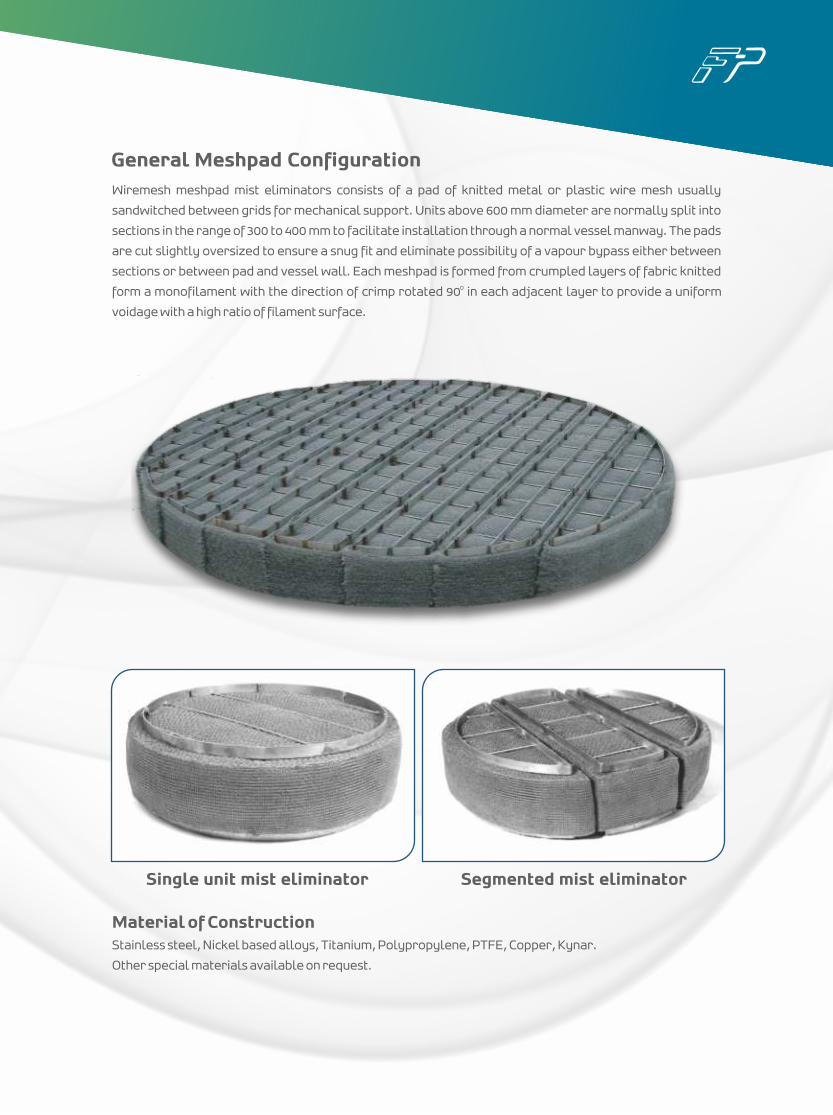
General Meshpad ConfigurationWiremesh meshpad mist eliminators consists of a pad of knitted metal or plastic wire mesh usually
sandwitched between grids for mechanical support. Units above 600 mm diameter are normally split into
sections in the range of 300 to 400 mm to facilitate installation through a normal vessel manway. The pads
are cut slightly oversized to ensure a snug fit and eliminate possibility of a vapour bypass either between
sections or between pad and vessel wall. Each meshpad is formed from crumpled layers of fabric knitted 0form a monofilament with the direction of crimp rotated 90 in each adjacent layer to provide a uniform
voidage with a high ratio of filament surface.
Material of ConstructionStainless steel, Nickel based alloys, Titanium, Polypropylene, PTFE, Copper, Kynar.
Other special materials available on request.
Single unit mist eliminator Segmented mist eliminator
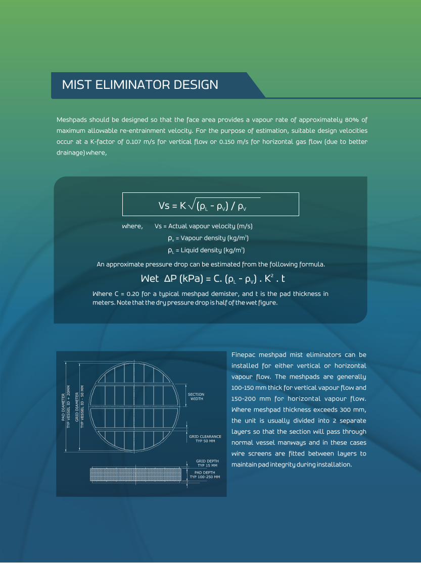
Meshpads should be designed so that the face area provides a vapour rate of approximately 80% of
maximum allowable re-entrainment velocity. For the purpose of estimation, suitable design velocities
occur at a K-factor of 0.107 m/s for vertical flow or 0.150 m/s for horizontal gas flow (due to better
drainage) where,
Finepac meshpad mist eliminators can be
installed for either vertical or horizontal
vapour flow. The meshpads are generally
100-150 mm thick for vertical vapour flow and
150-200 mm for horizontal vapour flow.
Where meshpad thickness exceeds 300 mm,
the unit is usually divided into 2 separate
layers so that the section will pass through
normal vessel manways and in these cases
wire screens are fitted between layers to
maintain pad integrity during installation.
Vs = K (ρ - ρ ) / ρL V V
where, Vs = Actual vapour velocity (m/s) 3ρ = Vapour density (kg/m ) v
3ρ = Liquid density (kg/m ) L
An approximate pressure drop can be estimated from the following formula.
2Wet ΔP (kPa) = C. (ρ - ρ ) . K . tL V
Where C = 0.20 for a typical meshpad demister, and t is the pad thickness in meters. Note that the dry pressure drop is half of the wet figure.
MIST ELIMINATOR DESIGN
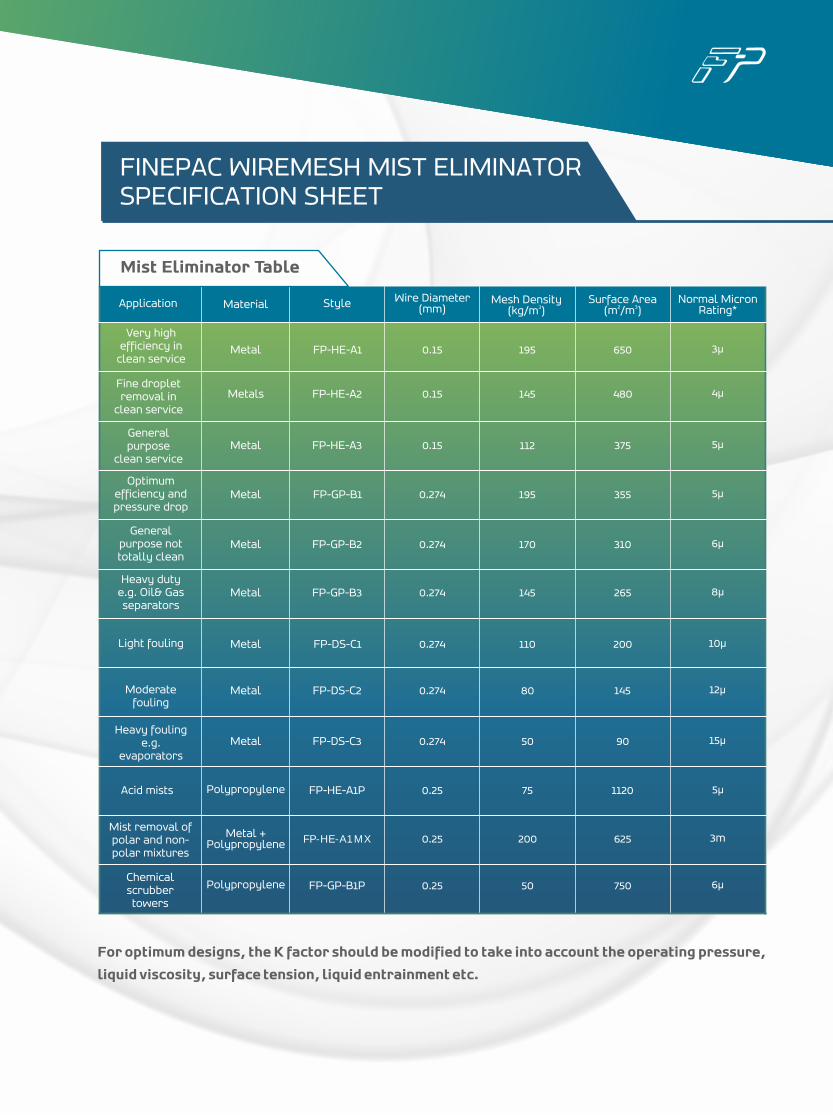
Application Material Style Wire Diameter (mm)
Mesh Density 3(kg/m )
Surface Area2 3(m /m )
Normal MicronRating*
Fine dropletremoval in
clean service
General purpose
clean service
General purpose not totally clean
Heavy duty e.g. Oil& Gas separators
Light fouling
Moderate fouling
Heavy fouling e.g.
evaporators
Acid mists
Mist removal of polar and non-polar mixtures
Chemical scrubbertowers
Metal
Metals
Metal
Metal
Metal
Metal
Metal
Metal
Metal
Polypropylene
Metal + Polypropylene
Polypropylene
FP-HE-A1
FP-HE-A2
FP-HE-A3
FP-GP-B1
FP-GP-B2
FP-GP-B3
FP-DS-C1
FP-DS-C2
FP-DS-C3
FP-HE-A1P
FP-HE-A1MX
FP-GP-B1P
0.15
0.15
0.15
0.274
0.274
0.274
0.274
0.274
0.274
0.25
0.25
0.25
195
145
112
195
170
145
110
80
50
200
75
50
650
480
375
355
310
265
200
145
90
1120
625
750
3μ
4μ
5μ
5μ
6μ
8μ
10μ
12μ
15μ
5μ
3m
6μ
Very high efficiency in
clean service
Optimum efficiency and pressure drop
FINEPAC WIREMESH MIST ELIMINATOR SPECIFICATION SHEET
For optimum designs, the K factor should be modified to take into account the operating pressure,
liquid viscosity, surface tension, liquid entrainment etc.
Mist Eliminator Table
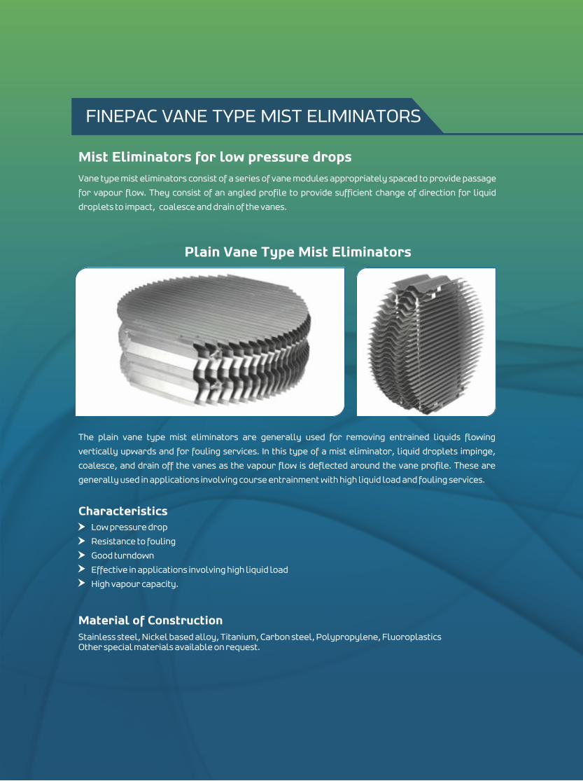
Vane type mist eliminators consist of a series of vane modules appropriately spaced to provide passage
for vapour flow. They consist of an angled profile to provide sufficient change of direction for liquid
droplets to impact, coalesce and drain of the vanes.
Mist Eliminators for low pressure drops
Plain Vane Type Mist Eliminators
The plain vane type mist eliminators are generally used for removing entrained liquids flowing
vertically upwards and for fouling services. In this type of a mist eliminator, liquid droplets impinge,
coalesce, and drain off the vanes as the vapour flow is deflected around the vane profile. These are
generally used in applications involving course entrainment with high liquid load and fouling services.
Characteristics Low pressure drop
Resistance to fouling
Good turndown
Effective in applications involving high liquid load
High vapour capacity.
Material of ConstructionStainless steel, Nickel based alloy, Titanium, Carbon steel, Polypropylene, FluoroplasticsOther special materials available on request.
FINEPAC VANE TYPE MIST ELIMINATORS
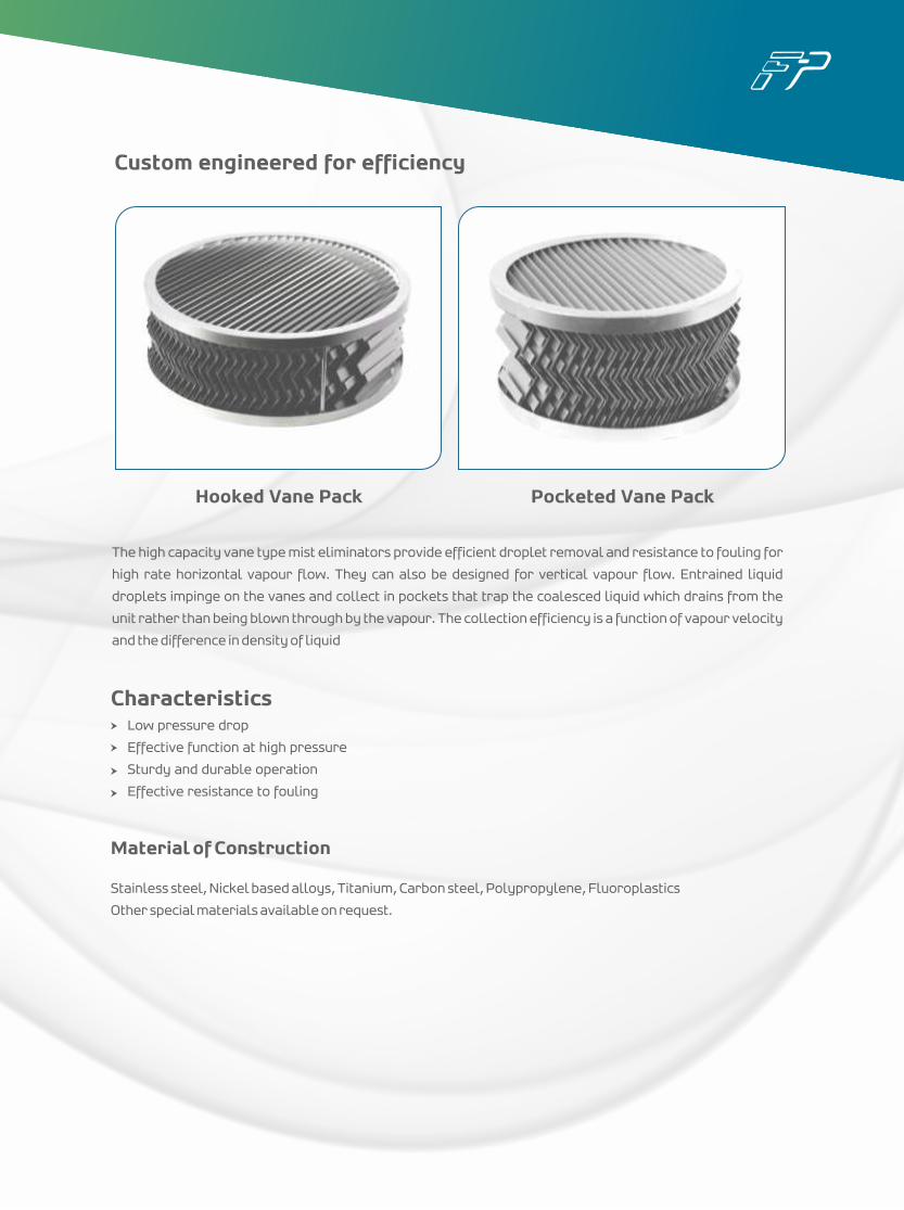
Custom engineered for efficiency
The high capacity vane type mist eliminators provide efficient droplet removal and resistance to fouling for
high rate horizontal vapour flow. They can also be designed for vertical vapour flow. Entrained liquid
droplets impinge on the vanes and collect in pockets that trap the coalesced liquid which drains from the
unit rather than being blown through by the vapour. The collection efficiency is a function of vapour velocity
and the difference in density of liquid
Hooked Vane Pack Pocketed Vane Pack
Material of Construction
Stainless steel, Nickel based alloys, Titanium, Carbon steel, Polypropylene, Fluoroplastics
Other special materials available on request.
CharacteristicsLow pressure drop
Effective function at high pressure
Sturdy and durable operation
Effective resistance to fouling
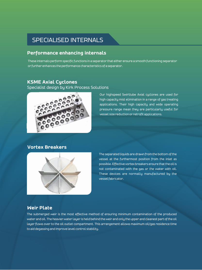
These internals perform specific functions in a separator that either ensure a smooth functioning separator
or further enhances the performance characteristics of a separator.
KSME Axial Cyclones
Our highspeed Swirltube Axial cyclones are used for
high capacity mist elimination in a range of gas treating
applications. Their high capacity and wide operating
pressure range mean they are particularly useful for
vessel size reduction or retrofit applications.
Vortex Breakers
The submerged weir is the most effective method of ensuring minimum contamination of the produced
water and oil. The heavier water layer is held behind the weir and only the upper and cleanest part of the oil
layer flows over to the oil outlet compartment. This arrangement allows maximum oil/gas residence time
to aid degassing and improve level control stability.
Weir Plate
The separated liquids are drawn from the bottom of the
vessel at the furthermost position from the inlet as
possible. Effective vortex breakers ensure that the oil is
not contaminated with the gas or the water with oil.
These devices are normally manufactured by the
vessel fabricator.
Specialist design by Kirk Process Solutions
SPECIALISED INTERNALS
Performance enhancing internals
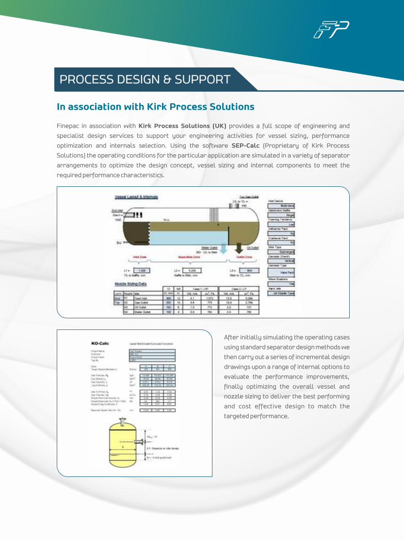
Finepac in association with Kirk Process Solutions (UK) provides a full scope of engineering and
specialist design services to support your engineering activities for vessel sizing, performance
optimization and internals selection. Using the software SEP-Calc (Proprietary of Kirk Process
Solutions) the operating conditions for the particular application are simulated in a variety of separator
arrangements to optimize the design concept, vessel sizing and internal components to meet the
required performance characteristics.
After initially simulating the operating cases
using standard separator design methods we
then carry out a series of incremental design
drawings upon a range of internal options to
evaluate the performance improvements,
finally optimizing the overall vessel and
nozzle sizing to deliver the best performing
and cost effective design to match the
targeted performance.
In association with Kirk Process Solutions
PROCESS DESIGN & SUPPORT
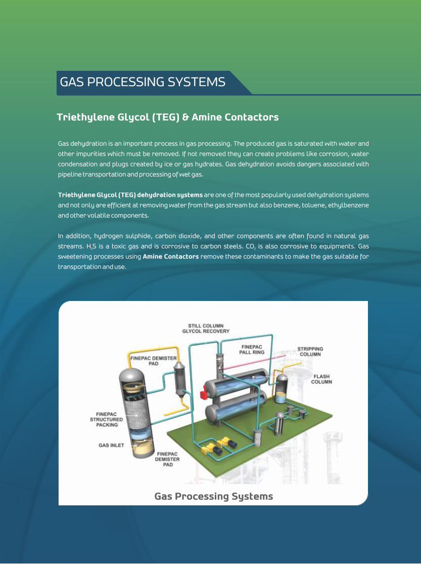
Gas dehydration is an important process in gas processing. The produced gas is saturated with water and
other impurities which must be removed. If not removed they can create problems like corrosion, water
condensation and plugs created by ice or gas hydrates. Gas dehydration avoids dangers associated with
pipeline transportation and processing of wet gas.
Triethylene Glycol (TEG) dehydration systems are one of the most popularly used dehydration systems
and not only are efficient at removing water from the gas stream but also benzene, toluene, ethylbenzene
and other volatile components.
In addition, hydrogen sulphide, carbon dioxide, and other components are often found in natural gas
streams. H S is a toxic gas and is corrosive to carbon steels. CO is also corrosive to equipments. Gas 2 2
sweetening processes using Amine Contactors remove these contaminants to make the gas suitable for
transportation and use.
Triethylene Glycol (TEG) & Amine Contactors
GAS PROCESSING SYSTEMS
Gas Processing Systems
In natural gas streams, water vapour needs to be removed to reduce pipeline corrosion and eliminate line
blockages caused by hydrite formation. If acidic gases are removed by amine treatment, then the gas will
be water saturated and will need to be dehydrated before entering the pipeline.
Working PrincipleThe gas dehydration process has a simple approach. Wet gas contacts dry glycol and glycol absorbs water
from the gas.
Wet gas enters the tower at the bottom and flows upwards. Dry glycol flows down the tower from the top
through the packing material to remove upto 10 ppm of moisture in dry gas. Finepac structured packings
are used for efficient moisture removal. The dehydrated gas leaves the tower at the top and goes to other
processing units. The water rich glycol leaves the tower at bottom and goes to a reconcentration system
consisting of a stripper and a regenerator. In this system Finepac random packings are used. Water escapes
as steam and purified glycol returns to tower where it contacts wet gas again.
Finepac Triethylene Glycol (TEG) Contactors
Natural gas streams may contain corrosive gases like H S, CO etc. which need to be removed. Amine 2 2
contactors remove these gases from the natural gas stream and make it fit for downstream processing.
Working PrincipleThe sour gas enters the contactor tower and rises through the descending amine solution. The amine
solution absorbs the corrosive gases. The amine contactor is equipped with Finepac structured packings.
The purified gas flows from the top of the tower. The amine solution carrying the absorbed acidic gases
leaves the tower to a regenerator to strip off the H S and CO . In this column the Finepac random packing is 2 2
used. Stream and acid gases separated from the rich amine are condensed and cooled respectively in a
reflux condenser. The regenerated amine is recycled back to the amine absorber to once again carry out
the gas sweetening process.
Finepac Amine Contactors
Benchmark for quality in vessel fabrication
To compliment its range of column internals and oil & gas internals Finepac also provides precision
engineered ASME Pressure vessel design & fabrication. Services for over 20 years we have partnered our
expertise in vessel fabrication with customer requirements to produce quality products.
We fabricate process equipments from all grades of stainless steel, carbon steel, high alloy steel, copper,
alluminium etc. We guarantee international quality fabrication inspected by reputed third party inspection
agencies.
We provide for
World class manufacturing facility
Customised design and fabrication services
Vessels certified with U stamp, S stamp and ASME certification
Vessels fabricated in accordance to nationally recognised standards including TEMA standard
Core Competencies
DesignFinepac’s services provide the experience of industry leading design and engineering to help ensure that
our solutions exceed customer expectation. We also provide for full technical support for your project from
concept through to installation.
Fabrication Craftsmanship and quality are our hallmarks. Our ASME certified welders & inspectors use the latest
technology to ensure that every product meets our rigid quality standard. Our fully equipped facilities
allow us to fabricate all our products inhouse which helps us to control the delivery time as well as the
possibility to fabricate any vessel large or small.
VESSEL FABRICATION
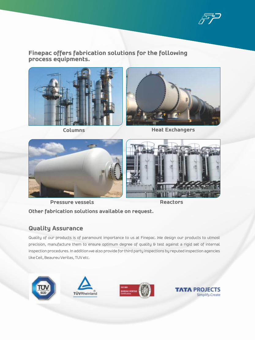
Finepac offers fabrication solutions for the following process equipments.
Other fabrication solutions available on request.
Quality AssuranceQuality of our products is of paramount importance to us at Finepac. We design our products to utmost
precision, manufacture them to ensure optimum degree of quality & test against a rigid set of internal
inspection procedures. In addition we also provide for third party inspections by reputed inspection agencies
like Ceil, Beaureu Veritas, TUV etc.
Columns Heat Exchangers
Pressure vessels Reactors