Oil Country 45000
70
“a commitment to quality” HYDRAULIC TUBING TONG 45000-100 OPERATION AND SERVICE MANUAL Oil Country Manufacturing, Inc. 300 W. Stanley Avenue Ventura, CA 93001 USA TEL: (805) 643 1200 FAX: (805) 643 6832 OSM-001 Last Revised Date: 10-12-01
description
Tubing Tong
Transcript of Oil Country 45000

“a commitment to quality”
HYDRAULIC TUBING TONG 45000-100
OPERATION AND SERVICE MANUAL Oil Country Manufacturing, Inc.
300 W. Stanley Avenue Ventura, CA 93001 USA
TEL: (805) 643 1200 FAX: (805) 643 6832
OSM-001 Last Revised Date: 10-12-01

1
TABLE OF CONTENTS
PAGE
• INTRODUCTION ………………………………………………………….. 2• WARNING …………………………………………………………………. 3• GENERAL DESCRIPTION ………………………………………………. 4• SPECIFICATIONS ………………………………………………………… 4-5• COMPONENT DESCRIPTIONS ………………………………………… 6-7• FIRST TIME START UP PROCEDURE ………………………………... 8• OPERATING INSTRUCTIONS ………………………………………….. 9-14• CHANGING JAW SYSTEM ……………………………………………… 15-16• CHANGING BRAKE BAND ……………………………………………… 17-18• RUNNING THE TONG ……………………………………………………. 19• TONG LINKAGE ADJUSTMENT ………………………………………… 20• GEAR SHIFT TENSION ADJUSTMENT ………………………………. 20• HYDRAULIC OIL SPECIFICATIONS ……………………………………. 20-21• GREASE SPECIFICATIONS …………………………………………….. 21• STEPS TO AVOID CORROSION ……………………………………….. 21• LUBRICATION AND PREVENTIVE MAINTENANCE SCHEDULE …. 22• TROUBLESHOOTING GUIDE …………………………………………… 23-24• STORAGE INSTRUCTIONS ….………………………………………….. 25• HOW TO ORDER PARTS ………………………………………………… 26• SAFETY PRECAUTIONS ………………………………………………… 26• TUBING TONG REPLACEMENT PARTS LIST ……………………….. 27-40• TUBING TONG SPARE PARTS LIST FOR ONE YEAR ……………… 41• M/S MANUAL BACK-UP ACCESSORY ……………………………….. 42-45• HDS BACK-UP 1.05-5 9/16 ………………………………………………. 46-54• STANDARD BACK-UP MOUNTS ……………….……………………….. 55-58• CONTROL VALVE ASSEMBLY …………………………………………. 59• MOTOR M25 REPLACEMENT PARTS LIST ………………………….. 60-61• TUBING TONG GAUGE ASSEMBLYS ………………………………… 62-63 (ILLUSTRATIONS 175, 145)• TORQUE CHARTS ………………………………………………………. 64-65• TECHNICAL CHARACTERISTICS OF OIL COUNTRY HYDRAULIC .. 66 TUBING TONGS

2
INTRODUCTION
This manual contains instructions on the maintenance and operation of the Oil Country Models45000 Hydraulic Tubing Tongs. Photographs with explanatory notes are included for assemblyand disassembly of these tongs. Full benefit of the long life and dependability of these units canonly be realized by proper operation and maintenance. The operator should familiarize himselfthoroughly with the contents of this manual before operating, making adjustments, or performingmaintenance procedures on this equipment.
For information regarding equipment operation, maintenance/repair, refer to theTable ofContents.
Oil Country Manufacturing, Inc. provides the information, data, and recommendations containedin this manual as a customer service. All are believed accurate; however, Oil CountryManufacturing, Inc. assumes no responsibility, implied or otherwise, for errors in, or for theapplication of the information, data, and recommendations presented herein.
The right is reserved to make changes in this manual at any time, without obligation.

3
WARNING1. DO NOT OPERATE, ADJUST, OR REPAIR THIS EQUIPMENT WITHOUT PROPER
TRAINING. 2. ADHERE TO ALL SAFETY WARNINGS. 3. DO NOT REMOVE GUARD DOORS. 4. A STIFF ARM BACK-UP IS STRONGLY RECOMMENDED, BUT IF A FLEXIBLE
LINE (CHAIN OR CABLE) MUST BE USED, THE LINE MUST BE HORIZONTAL ANDAT RIGHT ANGLES TO THE LONGITUDINAL AXIS WITH NO SLACK IN THIS LINE.
5. SHUT OFF ALL POWER AND DISCONNECT HYDRAULIC HOSES BEFORE
CHANGING TONG DIES/JAWS, MAKING ADJUSTMENTS, REPAIRS, ORLUBRICATING THIS EQUIPMENT.
6. KEEP ALL PARTS OF THE BODY AND CLOTHING AWAY FROM MOVING PARTS.
7. FAILURE TO COMPLY WITH THIS WARNING COULD RESULT IN PERSONAL INJURY AND EQUIPMENT DAMAGE.
WARNING
DO NOT OPERATE WHEN FRONT GUARD DOOR IS OPEN OR MISSING. KEEP HANDSCLEAR OF ROTATING PARTS. FAILURE TO COMPLY WITH THIS WARNING MAYCAUSE SERIOUS BODILY HARM.
WARNING
SNUB LINE MUST BE SECURELY ATTACHED TO REAR OF TONG AND TO ANCHORPOINT. ALL SLACK MUST BE OUT OF SNUB LINE BEFORE TONG IS OPERATED.FAILURE TO COMPLY WITH THIS WARNING MAY CAUSE SERIOUS BODILY HARM.

4
GENERAL DESCRIPTION
The Oil Country Models 45000 Hydraulic Tubing Tongs are fast, safe, and accurate tongs formaking up and breaking out 1.315” to 4.75” (Model 45000) O.D. tubing 100) O.D. tubing.Hydraulic power is directed to a manually controlled throttle valve and hydraulic motor unit.Fluid power input is converted to the rotary mechanical output which drives the tong’s gear train.The simple, but rugged gear train consists of a planetary type gear box mounted directly beneaththe motor, and a gear reduction system which provides the extra torque capacity. The tong issuspended in the derrick or mast by a wire line and swung onto the tubing. Tong jaws gripautomatically and the safety guard door closes. Operate the throttle in the forward position, andthe tubing is automatically made up to the required specifications as indicated on the torqueindicator gauge. The tong may also be used for light drilling, cutting, or remedial work.
SPECIFICATIONS
These specificatiions comprise the Oil Country 45000 Tongs.
Tong Performance Characteristics:
Maximum RPM (40 GPM, 151.4 LPM, Hi Gear) 105Running RPM (34 GPM, 128.7 LPM, Hi Gear) 93Make-Up Torque (ft.-lbs.) 5,440 FT LBS (750Kg/m)(Low Gear, 2000 PSI, 140.6 Kg/sq. cm)*Refer to “Torque Curve” charts onPages 61-62 for more detailed information.
Tong Equipment:
Four-Way Control Valve............................................................Manual Control for direction of tong rotationHydraulic Motor.............................................................................. Gear Type, Fixed displacement, 1 1/2” gears (3.8 cm) 2500 PSI
Maximum working pressure (175.8 Kg/sq.cm)Gear Box......................................................Planetary Type, 5-1/2” to 1” reductionHigh Pressure Hydraulic Hose........................................................1” (2.54 cm) 2250 PSI (148.2 Kg/sq. cm) working pressure 9000 PSI burst (632.8 Kg/sq. cm)Hydraulic Hose Couplings...........................Self-Sealing Quick Disconnect Type
Tong Weight..............................................................................560 lbs (254 Kg)

5

6
COMPONENT DESCRIPTION
Location of components described in this section can be located by referring to Hydraulic Tubing Tongillustration on Page 7.
Four-Way Control Valve:
A four-way control valve is mounted on the tong for the purpose of controlling the direction of the tongrotation. It is manually operated by the throttle lever.
Hydraulic Motor:
The hydraulic motor is mounted directly in front of the four-way valve on the tong. It converts hydraulicpower input to a rotary mechanical output and drives the tong’s gear train.
Hydraulic Hose Couplings:
The couplings on the tong are self-sealing and must be used whenever the hoses are disconnected. Use of thistype of coupling insures that the pressure and return hoses, four-way valve, and hydraulic motor being full ofoil, minimizing spillage.
Torque Gauge
There is a torque indicator assembly available to mount on the tong. The gauge provides accurate and directreadings of torque applied to tubing. NOTE: The torque gauge is calibrated, based on PSI vs ft/lbs. Thisgauge is for operator reference only. PSI must be adjusted at pressure relief control valve per charts on Pages64-65.

7

8
FIRST TIME START-UP PROCEDURE
The operator should read and follow these instructions before attempting to operate the tong the first time.When preparing to operate a new or re-conditioned hydraulic tubing tong, or an assembly that has been instorage, perform all of the operations listed below. Before operating (at the beginning of each shift), performDaily Operations in “Lubrication and Preventive Maintenance” procedure as described on Page 22.
Tong:
Clean tong and remove any packing material. Grease, oil, and lubricate brake band. Refer to figure 8 onPage 18. Function test linkage and shift mechanism for free operation. Suspend in derrick.
Hydraulic Hoses:
1. Adjust hydraulic system pressure to 500 PSI or less. 2. Shift tong to neutral position. 3. Engage hydraulic system clutch. 4. Push throttle lever toward tong. 5. Allow hydraulic fluid to circulate with tong gear shift lever in neutral position and the throttle advanced
for approximately five (5) minutes. 6. Set system pressure. 7. Check system for leaks. 8. If operating in cold weather, engage tong in high gear and rotate 2-3 minutes for warm-up. Check tong
linkage adjustments.

9
OPERATING INSTRUCTIONS
Tongs are assembled with parts carefully machined from selected materials. Each tong is thoroughly testedand inspected and is shipped from the factory with confidence that it will efficiently perform any job forwhich it is rated. The ensuing pages have been prepared for your guidance. These procedures are necessaryand should be followed for proper operation and maximum life of your tong.
Fluid Requirements:
To obtain the proper torque in making up and breaking out, the Tubing Tong requires a fluid volume ofapproximately 35 to 40 gallons per minute (132.5 LPM to 151.4 LPM) at 2000 PSI (70.3 Kg/sq. cm) and aminimum of 10 GPM (37.8 LPM) at 1000 to 2000 PSI (70.3 to 140.6 Kg/sq. cm). Every effort should bemade to keep the hydraulic system clean. The couplings on the tong are self-sealing and should be usedwhenever the hoses are disconnected. Use of this type of coupling insures the pressure and return hoses, four-way valve, and hydraulic motor being full of oil, minimizing spillage. Reference Page 20 for hydraulic oilspecifications.
Hose and Hose Connections:
When connecting the hoses, ensure there is no pressure in the system. Detach the fluid pump from the engineor shut the whole system down. ALWAYS CONNECT THE 1” (2.54 CM) FLUID RETURN HOSE TOTHE TONG FIRST, then connect the fluid supply hose. ALWAYS DISCONNECT THE FLUID SUPPLYHOSE FIRST (refer to Page 4). This prevents any pressure from building up in the hydraulic motor and seal.When attaching the hoses to the tong , DUST CAPS SHOULD ALWAYS BE USED WHENEVER HOSESARE DISCONNECTED. Should the open end of the coupling be allowed to come in contact with any dirt, itshould be very carefully cleaned before re-connecting and installing dust caps. A very small amount of dirt,sand, or foreign material can cause serious damage to the pump, hydraulic motor, and valves.
INSTALLATION AND MAINTENANCE OF TONG
1. Always wear eye protection prior to replacing dies.
2. Clean dies with wire brush daily to prevent damage to outside of tubing.
3. Inspect and change worn dies periodically to prevent slippage and damage to tubing.
4. Remove jaw and bushing from tong before changing dies.
5. Install dies correctly to ensure gripping on tubing. Dies must be installed with the teeth facing thedirection of rotation.
6. Roll pins in jaw and bushing must be installed correctly to prevent dies from falling down well whenoperating tong.

10
SUSPENSION OF TONGS IN DERRICK
1. Suspend the tong in the derrick with as long a line as possible, at a height to grip the tubing at least 6” ABOVE THE UPSET. The angle of hanging line from vertical when tongs are on tubing MUST NOT be great enough to pull the tong off the pipe.
2. Attach Back-up Line
A back-up line, automatic or retraction, is attached to the back-up ring. The back-up line must be ofsufficient strength and be properly secured.
BACK-UP LINE MUST BE HORIZONTAL TO TONG: THAT IS, IT MUST NOT PULL UPOR DOWN ON TONG WHILE IN OPERATION.
For correct torque readings, the back-up line MUST BE ON A 90 DEGREE ANGLE WITHTONG.
Oil Country recommends the use of a safety sling to prevent injury of personnel caused by failure ofmain back-up line or stiff arm assembly. The safety sling must be attached to the safety eye on theback of the tong and fastened to the rig or to a secure tie down.
NOTE: A back-up line must always be used, with or without the coupling back-up assembly.
3. Connect hydraulic hoses and start power unit.
4. Swing tong on tubing joint. Advance the throttle enough to take the slack out of the back-up line. This will put the tong in a level position.
NOTE: Tong must be leveled on tubing and over the hole by adjusting bolts (ref. 121) on hanger assembly(Page 27). Spring hanger should not be completely compressed from the weight of the tong. Tong shouldhave some bounce. If spring is completely compressed from the weight of the tong, it should be replaced.

11
STIFF ARM ASEMBLY
OPERATION AND INSTALLATION
ILLUSTRATION 032 PAGE 12
The Oil Country Stiff Arm is designed to help pull tubing tong on and off pipe and hold tong awayfrom well when tripping pipe. When running tong the operator can shift valve to pull off positionallowing the tong to swing away from well when the grip of the tong is released thus the floor handdoes not have to pull or push the tongs.
Stiff arm, post, item #2 is to be mounted on rig in vertical position on right or left derrick leg. Item#1 will be welded to clamps provided by customer.
Clamps are made to clamp on derrick leg. Three are required, one to hold the back of pull backcylinder, two pieces of metal are provided, cut desired length item #14 and wielded to clamp. Twopieces item #1 are to be cut to length and wielded to clamps and installed on derrick leg. Now postitem #2 can be installed in bearings. Item #5, item #12 plate can be welded in place, the plate canbe wielded in any place up and down the post, where the back of the cylinder can be hooked toclamp.
Now install stiff arm item #3 and #4, connect with bolt and nut item #8 and #9. Now the safetysling item # 6 can be connected to rig. With tong hanging from crown the stiff arm can now beconnected to back of tong at the swivel eye with nut and bolt #7 and #9. Now connect other end ofsafety sling item #6 to eye on left or right side of tong. Item #4 can be adjusted in or out byremoving pin and clip items #10 & #11.
Now hoses can be connected to air cylinder item #13 and to hand valve two hoses hook between aircylinder and hand valve the other is connected to main air supply.
IMPORTANT: THE TONG MUST HANG LEVEL AND THE STIFF ARM LEVEL WITHTONG, STIFF ARM MUST BE 90 DEGREE ANGLE WITH TONG.
IF THIS IS NOT ESTABLISHED THE TUBING WILL BE MARKED MORE THENNECESSARY AND DIE LIFE WILL BE GREATLY SHORT.

12

12-1

13

14
PART NUMBER 58019-101
UNIVERSAL STIFF ARM ASSEMBLY
FOR OPEN FACE TONG
REF. NO. PART NO. DESCRIPTION QTY.58019-101 Stiff Arm Assembly Complete 158019-201 Stiff Arm Assembly Less Rig Bracket (Ref. 5) 1
1 58022-300 Female Arm Weldment Assembly 12 58021-300 Male Arm Weldment 13 992252-84 Safety Sling 84” 14 992331-3A-06 Shackle 1/2” 25 58028-300 Bracket, Rig 16 58025-400 Anchor, Pin Assembly (Ref.6, 7, 8) 27 992164-17 Nut, 3-1/4” 28 992047-13 Hair Pin 29 992007-07 Bolt 5/8” 1
10 992047-11 Haif Pin 111 992164-15 Nut, 5/8” 1

15
Tong Fails to Go on Tubing:
If the tong fails to go onto the tubing, it is probably because the jaw is partially closed. In thiscase, run the motor in the direction that will fully open the jaw, and then proceed to install thetong on the tubing. If this fails to work, check both the jaw and bushing for proper size andinstallation. Refer to chart below.
Jaw and Bushing Sizes:
Jaw and bushing sizes are stamped according to the actual O.D. of the tubing that they will fit -not the nominal size of the tubing.
NOMINAL STAMPED NOMINAL STAMPED3/4” 1.050” 2-1/2” 2-7/8”1” 1.315” 3” 3-1/2”
1-1/4” 1.660” 3-1/2” 4”1.750” 4” 4-1/2”
1-1/2” 1.990”2-1/16”
2” 2-3/8”
CHANGING OR REVERSING JAW AND BUSHING
The jaw and bushing are reversible, depending upon the desired direction of rotation. If the jawis installed on the left side (Figure 5, Page 16) (standing in front of the tong, as you look into theopening of the tong), the tong will rotate the tubing to the left. When the jaw is installed on theright side (Figure 4), it will rotate the tubing to the right (the direction of tubing rotation whengoing into the hole).
Removal of Jaw and Bushing:
Position the tong as if it were to go onto the tubing. Reverse the bushing as indicated in Figure 2.Reverse the motor and move the outer ring slightly. This will remove any force against the pivotpin of the jaw so it will come out easily (Figure 3). Remove the pivot pin and jaw.
NOTE: It is difficult to remove or install the jaw while the bushing is still in place.
Reversal of Jaw and Bushing:
Remove the jaw and bushing as outlined above. Move the outer ring slightly so there will beroom to get the lip of the jaw in back of the front roller of the outer ring. Make certain that thejaw and bushing are the correct size. Install the jaw as shown in Figure 3. Install the bushing asshown in Figure 2.

16

17
CHANGING THE TUBING TONG BRAKE BAND
Align the opening of the inner and outer rings with the opening in the tong frame, referenceFigures 6-9 on Page 18. Remove the two cap screws from the brake band cover plate and liftcover plate. Remove the old brake band, which is located directly under the cover plate. Applygrease liberally to the lining of the new brake band and to the inside of the eye on each end of theband. Put the new brake band on the inner ring and remove the wooden spacer. If the newbrake band does not have a spacer, a piece of wood 5-1/2” long can be inserted. The brake bandcover can then be closed and the two cap screws installed.
NOTE: When the cover plate is down, ensure that the two brake pins in the cover plate enter the eye openings at each end of the brake band.

18

19
RUNNING THE TONG
Before operating the tong for the first time, refer to “First Time Start-Up Procedure” on Page 6.
Making Up the Tubing
With the tong suspended, position gear shift lever (located towards the front of the tong) in highgear (refer to illustration on Page 7). With the safety guard on the front of the tong open,position tong onto the tubing. (The safety guard will automatically close as tubing enters.) Itis necessary for the tong to be in this positiion for the jaws to grip. DO NOT SWING THETONG ONTO THE TUBING TOO HARD, AS IT MAY CAUSE THE TONG TOBOUNCE OFF. Engaging the throttle causes the jaws to grip and rotate the tubing. Thepressure at which the pump unit is set determines the make-up torque.
Reference the torque curve charts on Pages 64-65 for the hydraulic pressure required for specifictorque values.
TORQUE CURVE
OIL PRESSURE
On high pressure well, stall pressures should be higher. High torque and critical joints should bemade up using the manufacturer’s recommended torque values and taking direct readings fromthe torque indicator gauge. Accurate readings are also dependent upon proper tong suspension.
To release the tongs from the tubing, reverse tong by pushing the throttle back until the gap in therotor comes in alignment with that of the case. The jaws will automatically release.

20
TONG LINKAGE ADJUSTMENT
SHIFT ROD ADJUSTMENT
Shift rod adjustment is accomplished with jam nuts (ref. 120) located on each end of rod (ref.120). Adjust gear shift handle (ref. 304) in neutral position (handle is tilted slightly forward).See illustration on Page 27.
THROTTLE ADJUSTMENT
The throttle rod adjustment is set with the safety arm (ref. 186) and with the door (ref. 99) in openposition. Adjust safety bar (ref. 187) to match the slot in the safety arm and secure by tighteningjam nut (ref. 171).
NOTE: Proper adjustment allows full throttle in both directions with the door closed and prevents throttling when door is open.
GEAR SHIFT TENSION ADJUSTMENT
Adjusting gear shift tension is accomplished by turning set screw (ref. 60) in until gears will notshift and backing out set screw until shifting is smooth. There will be approximately threethreads of the set screw exposed beyond the transmission cover (ref. 11) when shiftingmechanism is new. Set screw position is also a wear indicator for the shift rod fork.
HYDRAULIC OIL SPECIFICATIONS
Performance and service life of all other components of a hydraulic system are affected by thehydraulic system fluid. Some of the factors especially important in the selection of oil for use ina hydraulic system are:
1. The oil must contain the necessary additives to ensure high anti-wear characteristics. Not allhydraulic oils contain these in sufficient amounts.
2. The oil must have proper viscosity to maintain adequate sealing and lubricating quality at the
expected operating temperatures of the hydraulic system. 3. The oil must have rust and oxidation inhibition for satisfactory system operation.
Viscosity of fluid is a measure of its resistance to flow as well as its ability to prevent metal-to-metal contact of moving parts. It is recommended that the following maximum and minimumviscosity ranges of the oil at start-up and during running be maintained:
Nominal: 150-3000 viscosity at 100 F. (38 C)Running: 70-250 viscosityAt Start-up: 4000 viscosity maximum
An anti-wear type of heavy-duty industrial hydraulic oil is recommended. This anti-wear type ofoil offers superior protection against pump and motor wear, and has the advantage

21
of long service life. In addition, these oils provide good dumulsibility as well as protectionagainst rust. A good grade SAE 20 “MS” automotive crankcase oil can be substituted. Formost efficient operation, the temperature of the oil should not exceed 150 F. (66 C).
GREASE SPECIFICATIONS
Due to the operating environment of the tong, a water insoluble grease is required. The greaseshould have high pumpability to permit application during very cold weather. The greaserecommended for cold weather operation is Shell B&B Code 70919, which conforms toGovernment Specification MIL-G-10924-C. In milder climates, an all-purpose grease suchas Shell Alvina #2 is recommended.
STEPS TO AVOID CORROSION
Every trip, lubricate all grease fittings with the recommended grease. With an oil can, lubricatethe following: throttle mechanism and the shift mechanism. Lubricate brake band andfriction surface with only enough light oil to keep the surface from rusting when the tong isnot in service. If the tong does not grip the pipe, the cause may be too much grease on thebrake band. This can be remedied by wiping the brake band and friction surfaces clean of allgrease, later re-lubricating with grease. The tong should be cleaned periodically or after eachshift when used around salt water.

21-1

21-2

22
IMPORTANT LUBRICATION AND PREVENTIVE MAINTENANCE
To obtain the long life and best performance from a tong, the operator must adhere to the following instructions on
lubrication and preventive maintenance. Areas to be oiled or greased, and proper care of the hydraulic hoses andcouplings. The daily instructions pertain to routine or daily operation of a tong and not to new equipment. Fornew tongs, follow instructions given in “First Time Start-Up Procedures” on Page 8. The time intervals given inthe instructions refer to actual hours on the tong.
Item 1: After every trip, lubricate the following with 30W oil or equivalent; throttle mechanism shift mechanism, guard door
spring, front end of reverse rod, and jaw pins. Item 2: After every trip, all grease fittings should be lubricated with the recommended grease. (See Page 21). In addition to
those shown, there are fittings on each guide roller shaft, one on the bottom transmission cover and one on theunderside of the handle. There is no danger of over-greasing the tong. Under continuous operations, such aswhen tong is used for light drilling operations, grease the tong every hour.
Item 3: During assembly and disassembly, inspect couplings to ensure that all openings are free of dirt and debris. Use clean
rag and solvent when cleaning, if required. Take proper precautions to ensure that the solvent does not enter hose.Hoses should be wiped clean, and if storage is necessary, install dust covers and store in a clean, warm climateprotected from direct sunlight.

23
TROUBLESHOOTING
A. TONG RUNNING TOO SLOWLY
1. Pump intake line plugged Clean intake line and filter.2. Reservoir oil level too low Add oil.3. Air leak in pump intake line
(Oil in reservoir may be toofoamy).
Identify source of leak and make necessary repairs.
4. Pump speed too slow Check manufacturer’s speed recommendations and actualspeed of pump. Vane type pumps will not prime ifrunning too slowly.
5. Excessively worn or damagedpump or tong
Replace. Follow manufacturer’s recommendations.NOTE: To determine which is defective, disconnectpump from motor, test pressure and volume of pump.
6. Pump control improperly set(variable delivery pumps)
Check position of control.
7. Viscosity of oil too high Some pumps will not prime if the oil is too heavy. Checkmanufacturer’s recommendations and viscosity of oilused.
8. Viscosity too low:a. Excessive heat See No. 9 below (restriction in line between power unit
and tong).b. Contamination of oil; i.e., diesel, gasoline, etc.
Change oil.
c. Improper grade of oil Change to oil of a higher viscosity or of a better viscosityindex.
9. Restriction in line betweenpower unit and tong
This condition may be detected when pump pressure is notreaching the tong or when excessive back pressure iscreated in the return line. The return line pressure shouldbe approximately 100-150 PSI (7.03 - 10.54 Kg/sq.cm).Check self-seal couplings to ensure they are properlyengaged. Check self-seal couplings for rubber pieceslodged in valves. If couplings are clear, check forcollapsed inner layers of the return hose.
10. Hose connections not made upproperly.
Check hose connection procedure in “OperatingInstructions” on Page 9.
B. TONG WILL NOT DEVELOP SUFFICIENT TORQUE
1. Tong valve or relief valve ontong not working:a. Valve stuck Check for dirty or gummy sludge. Check for con-
tamination of oil. Check for broken spring valve.b. Valve leaking Check valve seat for scouring. Check oil seals. Check for
particles stuck under valve stem.

24
2. Stuck, worn, or damaged pumpparts
Inspect and clean. Replace worn or broken parts. Checkrelief valve.
3. Pump speed too slow Check motor speed.4. Oil viscosity too high. Some pumps will not prime if oil is too heavy. Check
viscosity at working temperature (also at initialtemperature, if this is considerably lower).
5. Oil viscosity too low See No. 9 below (restriction in line between power unitand tong).
6. Oil by-passed to reservoir Check relief valve for proper operation. Check directionalvalves; open center neutral position should return oil tothe reservoir.
7. Tong motor worn or damaged,allowing excessive slippage.
Repair and/or replace worn or damaged parts.
8. Excessive drag in tong due todamaged bearings or gears
Repair and/or replace worn or damaged parts.
9. Restriction in line betweenpower unit and tong
This condition may be detected when pump pressure is notreaching the tong or when excessive back pressure iscreated in the return line. Check self-seal couplings tomake certain they are properly engaged.
C. FAILURE OF JAWS TO GRIP TUBING
1. Improper tong suspension Refer to Page 10.2. Dull dies Replace or clean with wire brush.3. Brake band worn Replace. Refer to Page 17.4. Improper jaw size Refer to Page 3.
D. FAILURE OF TONG TO SHIFT OR DIFFICULTY OF SHIFTING
1. Shifting mechanism is worn Replace.2. Shift is attempted at too high an
R.P.M.Shift at lower R.P.M. or after momentary stop. Shift withrotor opening at rear of tong.
E. POOR DIE LIFE
1. Improperly suspended tong;tong hanger bottomed out
Refer to hanging procedure in “Operating Instructions” onPage 9.
2. Tong worn excessively Replace and/or repair tong, as required.3. Improperly reconditioned dies Replace jaw.

25
STORAGE
Preparing Tong for Storage:
When a tong is to be stored or removed from operation, special precautions should be taken to protect the interior andexterior of the tong from rust accumulation and corrosion. It will be necessary to remove all rust or corrosioncompletely from any exposed part before applying a rust preventive compound. Therefore, it is recommended that thetong be processed for storage as soon as possible after removal from operation. Storage should be in a building whichis dry and can be heated during the winter months. Moisture absorbing chemicals are available commercially for usewhen excessive dampness prevails in the storage area. The recommended storage preparation is detailed below.
TEMPORARY STORAGE:
To protect a tong during storage for periods of 30 days or less: 1. Clean entire exterior of tong with solvent and thoroughly dry. Cleaning is especially important if unit has been
used around salt water. 2. Grease and oil the tong as recommended under “Lubrication and Preventive Maintenance” procedure on Page 22. 3. Cover the entire unit with a good weather-resistant tarpaulin or other cover if it must be stored outdoors. A clear
plastic cover is recommended for indoor storage.
EXTENDED STORAGE:
To protect a tong for storage for periods exceeding 30 days, proceed as follows:
1. Perform Steps 1, 2, and 3 of “Temporary Storage” procedure above. 2. Spray all exterior surfaces of the tong and power unit with a suitable liquid automobile body wax, a synthetic
resin varnish, or a rust preventive compound. 3. Cover the tong and power package with a good weather-resistant tarpaulin or other cover if it must be stored
outdoors. A clear plastic cover is recommended for indoor storage. The stored unit should be inspectedperiodically. If there are any indications of rust or corrosion, corrective steps must be taken to prevent damage tothe parts. Perform a complete inspection at the end of one year and apply additional treatment, as required. Forrestoring the tong to service, refer to “First Time Start-Up Procedure” on Page 6.
26
HOW TO ORDER PARTS
When ordering parts for your tubing tong, refer to Parts Lists. Use schematic illustrations to locate correct itemnumber and part number from list.
When ordering include:
Quantity requiredPart Number (NOT item number)Part NameTong Model NumberTong Serial Number
SAFETY PRECAUTIONS
Your tubing tong has been carefully designed with safety features built into your unit. Realizing, however, thatpower-driven equipment is only as safe as the operator who is at the controls, it is extremely important that theoperator observe the following safety precautions.
1. Operate the tong from the back-up line side only (does not apply to front control tongs). 2. Never change a jaw or put hands within the rotating parts of the tong while tongs are connected to hydraulic
hoses. 3. Never remove or operate the tong without the guard doors in place. 4. Do not exceed the maximum pressure for which this system is rated. 5. Always use a back-up line for all tong operations. 6. Keep loose fitting clothing away from the rotating parts of the tong.


29

30
TUBING TONG REPLACEMENT PARTS LIST FOR45000
REF. NO. PART NUMBER NO.REQ’D
DESCRIPTION WGT.LBS
55011-100 1 Bottom Transmission Assembly (Ref. 11,12, 17, 48, 50-52, 61-64, 72, 78, 97)
11 45011 1 Bottom Transmission Cover 10.0012 45012 1 Bushing .0615 45015 1 Bearing Spacer .0616 45016 1 Thrust Washer .1317 45017 1 Shift Fork .0618 45018 4 Gear Shaft Bushing .13
45022-100 1 Hanger Assembly (Ref. 19, 22, 70, 121, 127,132, 169)
19 45019 1 Hanger Balancing Screw .1320 992093-12 1 Nut22 45022-200 1 Hanger 17.00
45023-100 1 Hanger Suspension Assembly (include Ref.127, 160, 223-229)
6.75
23 45023-1 1 Safety Sling 1.0024 45024-200 1 Door .2525 45025 1 Door Spring .2526 45026 2 Idler Gear 1.0027 45027 2 Idler Gear Shaft 1.0028 45028 2 Thrust Washer .2529 45029 2 Thrust Washer .2530 45030 4 Guide Roller Shaft .2531 45031 2 Guide Roller Shaft .2532 45032 1 Cluster Gear Shaft .0633 45033 1 Thrust Washer .1334 45034 1 Thrust Washer .1340 45040-01 6 Guide Roller 5.0041 45041 6 Guide Roller Spacer .0642 45042 1 103 Tooth Rotor 40.00
45042-200 1 Rotor Assembly (include. ref. 72, 277-280,287)
62.25
44 45044-200 1 Tubing Tong Housing 140.0047 45047-200 1 Tong Cover 54.0048 45048 1 Pinion Shaft 2.5050 45050 1 29 Tooth High Speed Pinion 1.50

31
TUBING TONG REPLACEMENT PARTS LIST FOR45000
REF. NO. PART NUMBER NO.REQ’D
DESCRIPTION WGT.LBS
51 45051 1 14 Tooth Low Speed Pinion 2.0052 45052 1 Retaining Ring .0654 45060 1 Cluster Gear Replaces Items 57-5960 992082-96 4 Long Dowel .1361 940007-304 1 Bearing .2562 940048-5205 1 Bearing .5063 992134-86 3 Set Screw .0664 900572-5 1 1/4” Ball .0665 992007-05 2 Cap Screw .0666 992007-03 6 Cap Screw .0667 992051-14 16 Lockwasher .1368 992005-03 2 Cap Screw .1369 992051-10 4 Lockwasher .1370 992162-09 7 Nut .0671 992082-95 2 Short Dowel .0672 992073-01 10 Grease Fitting .0676 992073-04 6 Grease Fitting .0678 992253-200 1 Snap Ring .1381 992011-138 1 Roll Pin .1389 992007-02 4 Cap Screw .1393 940021-206 1 Bearing .5095 45095 1 Bearing Set .5096 45096 2 Bearing Set .5097 45097 1 Transmission Spring .0698 45098 2 Motor Bushing .1399 45099 1 Caution Plate .06
45099-1 4 Drive Pin .01992209-01 1 English Caution Plate .06
104 45104 1 Top Cover 13.00106 45106 1 Top Cover Hinge .06
45106-200 1 Top Cover Hinge Assy Ref 150, 151, 160 .07115 940007-304 12 Bearing .25
45116-200 1 Tail Handle Assembly (Ref. 116, 117) 39.06116 45116 1 Tail Handle 36.00
116-1R 45116-250 1 Throttle Back Guard (For tong w/ relief valve)(Ref 116-1R, 202, 417, 241)
1.5
116-1 45116-1 1 Tong Handle Back Guard 3.00117 45117 3 Shift Bushing .06119 900470-16 2 End Yoke .06

32
TUBING TONG REPLACEMENT PARTS LIST FOR45000
REF.NO.
PART NUMBER NO.REQ’D
DESCRIPTION WGT.LBS
120 992107-10 2 Jam Nut .06121 992005-04 6 Cap Screw .13125 45125 1 Shift Lever 1.00126 992011-138 4 Roll Pin .13127 992012-45 2 Cotter Pin .13128 45128 1 Shift Link .50129 992049-125 2 Clevis Pin .13130 992012-34 6 Cotter Pin .06131 992049-106 4 Clevis Pin .13132 992049-165 2 Clevis Pin .13133 45133-200 1 Gear Housing Assembly (Ref. 133-135) 8.00134 45134 1 Inner Gear 2.00135 992082-38 2 Dowel .13136 45193 2 Stud .13137 45137-200 1 Gear Frame Assembly (Ref. 137-140) 3.00138 992082-97 3 Planet Gear Shaft (WAS 45138) .06139 45139 6 Bearing .06140 45140 3 Planet Gear .50141 903317-17 1 Bearing .31142 45142 1 Thrust Washer .13143 940016-208 1 Bearing .25144 45144-200 1 Back Swivel 1.00145 992005-17 2 Cap Screw .25146 992089-09 3 Ny Lok Nut .06147 992164-05 2 Hex Nut .06149 992155-04 2 Flat Washer .06
150-1 992066-04 2 FH Socket Screw .13150-2 992066-03 2 FH Socket Screw .13150-3 992005-14 1 Screw .5151 992107-05 2 Heavy Thin Nut .06152 992003-10 1 Cap Screw .06153 992004-07 1 Cap Screw .13154 992089-05 6 Nylon Lock Nut .06155 992089-07 1 Nylon Lock Nut .06156 992003-08 1 Cap Screw .13157 992217-01 1 Shoulder Bolt .06158 992011-102 1 Roll Pin .06159 992017-13 3 Cap Screw .06160 992213-15 1 Hex Nut .06161 992025-07 4 Soc Screw .06162 900706-240 2 Hydraulic Hose 2.00
162-S 900706-241 1 Hydraulic hose (Short) (For relief valve) 1.50163 992141-S-12-12 2 Hydraulic Fitting 90° NPT (For Tong With Relief
Valve) .50
163 992141-S-12-12 1 Hydraulic Fitting 900 NPT X NPT .50164 992138-S-12-12 2 Hydraulic Fitting .50

33
TUBING TONG REPLACEMENT PARTS LIST FOR45000
REF.NO.
PART NUMBER NO.REQ’D
DESCRIPTION WGT.LBS
165 992434-S-12-12 1 Hydraulic Fitting Tee (For Tong With Relief Valve) .50166 46056 2 Hex Coupling NPT X NPT
(For Tongs Without Relief Valve).13
166 46056 1 Hex Coupling NPT X NPT (For Tong With Relief Valve) .7168 992142-S-12-12 2 Adapter 90° elbow .75 NPT X .75 FNPT
(For Tong With Relief Valve).50
169 992008-19 1 Cap Screw .50170 992338-S-12-12 2 Adaptor 90° elbow .75 NPT X .75 NPT
(Tong with relief valve).7
171 992107-08 2 Jam Nut .06172 900470-7 1 End Yoke .50184 45184 1 L.H. Door Spring Pin .50185 45185 1 R.H. Door Spring Pin .50186 45186 1 Safety Latch Plate .50187 45187 1 Safety Latch Bar .50188 45188 1 Control Valve Swivel Yoke .25189 45189 1 Fixed Control Valve Yoke .25190 45190 1 Control Valve Pivot Plate .50191 45191 1 Control Valve Link Assembly (Ref. 130, 131, 190) .75192 45192 1 Safety Latch Pin .13200 992005-05 2 Cap Screw .13201 45201 1 Motor Adapter 2.00202 992019-06 4 Cap Screw .13203 45203-1 1 Rear Shift Lever Handle 5.00221 992023-05 2 Cap Screw .25222 45030-100 1 Dual Suspension Hanger Assy (option) 10.0222 45023-100 1 Single Suspension Hanger Assy (option)
45240 1 Control Valve Assembly (Ref. 241-243, 245) 15.0800024 1 Control Valve Repair Kit
241 992019-03 4 Control Valve End Cap Bolt .20242 45242 1 Control Valve End Cap 2.00243 45243 1 Control Valve Body 11.0244 970400-5 1 Hydraulic Motor Standard 47.0245 45245 1 Control Valve Spool 2.00277 45277 3 Large Roller 1.75278 45278 2 Small Roller 1.00

34
TUBING TONG REPLACEMENT PARTS LIST FOR45000
REF. NO. PART NUMBER NO.REQ’D
DESCRIPTION WGT.LBS
279 45279 5 Roller Bushing .20280 45280 5 Roller Pin .80287 45287 1 Inner Ring 10.00288 45288 1 Brake Band 5.00289 45289 2 Brake Band Pin .50290 45290 2 Jaw Pin .75291 See Jaw Assemblies
292 See Jaw Assemblies
293 See Jaw Assemblies
294 See Jaw Assemblies
295 992015-02 3 Socket Screw .20300 45300 1 Shift Bracket 3.00301 45301 1 Throttle Bracket 5.00302 45302 1 Shift Rod 1.00303 45303 1 Throttle Rod .50304 45304 1 Shift Handle 1.00305 45305 1 Throttle Handle .50312 992151-S-12-12 1 Hex Nipple (for relief valve assy) .50314 943972-45 1 Relief Valve (for relief valve assy) 5.00337 900706-241 1 Hydraulic Jumper Hose 1.25401 45403-101 1 Torque Gauge Assembly Psi/ Ftlbs See ILL-
175 2.00
401 45403-102 1 Torque Gauge Assyembly Bar/ Nm See ILL-145 .50405 700B-04-024-02 1 1/4” Hose Assembly .25406 45406 1 90 Degree Elbow Adapter .10408 992138-S-4-4 1 Straight Hydraulic Fitting .13
45410-200 1 Back Guard Assembly (ref. 147, 410, 411)45430-200 1 Back Guard Tong Assy (For Relief Valve
Tong Assy) Ref. 410R, 411R, 415, 416, 1472.50
410R 45430-01 1 Back Guard (For Tong With Relief Valve) 2.40410 45410 1 Back Guard 2.00411 992327-018 1 U-Clamp .10
411R 992327-019 1 U-Clamp (For Tong With Relief Valve) 1.00414 992453-12 2 Hydraulic Swivel 3/4” NPT 1.00
45407-202 2 Hydraulic Swivel Assy 3/4” NPT (Ref 414,418)
1.5
415 992005-03 1 Screw (For Tong With Relief Valve) .10416 992116-09 1 1/2” Nut (For Tong With Relief Valve) .10417 992051-06 1 3/8” Lock Washer (For Tong With Relief Valve) .10418 992131-S-16-12 1 Hydraulic Fitting 3/4 NPT X 1” NPT .20

35


37
=TUBING TONG REPLACEMENT PARTS LISTFOR 55000/56000/45000
JAW ASSEMBLIESREF. NO. PART NUMBER NO.
REQ’DDESCRIPTION WGT.
LBS45291H-100 1 1.66 Jaw Assembly (1-1/4” Pipe) 8.50
291 45291H 1 1.66 Jaw 6.50293 45293H 1 1.66 Die 2.00294 992012-72 2 Cotter Pin .01
45291F-100 1 1.900 Jaw Assembly (1-1/2” Pipe) 7.50291 45291F 1 1.900 Jaw 6.50293 45293F 1 1.900 Die 2.00294 992012-72 2 Cotter Pin .01
45291G-100 1 2.06 Jaw Assembly 6.50291 45291G 1 2.06 Jaw 5.50293 45293G 1 2.06 Die 2.00294 992012-72 2 Cotter Pin .01
45291A-100 1 2-3/8” Jaw Assembly 5.50291 45291A 1 2-3/8” Jaw 4.50293 45293A 1 2-3/8” Die 1.00294 992012-72 2 Cotter Pin .01
45291B-100 1 2-7/8” Jaw Assembly 5.50291 45291B 1 2-7/8” Jaw 4.50293 45293B 1 2-7/8” Die 1.00294 992012-72 2 Cotter Pin .01
45291C-100 1 3-1/2” Jaw Assembly 4.75291 45291C 1 3-1/2” Jaw 4.50293 45293C 1 3/8 X 1 X 3 7/8 Die .25294 992012-72 2 Cotter Pin .01
45291K-100 1 3-3/4” Jaw Assembly 4.37291 45291K 1 3-3/4” Jaw 4.25293 45293K 1 3/8 X 1 X 2 1/4 Die .12294 992011-132 2 Roller Pin .01
45291E-100 1 4” Jaw Assembly 4.75291 45291E 1 4” Jaw 4.50293 45293C 1 3/8-1 X 3 7/8 Die .25294 992012-72 2 Cotter Pin .01
45291L-100 1 4-1/4” Jaw Assembly 4.12291 45291L 1 4-1/4” Jaw 4.00293 45293K 1 3/8 X 1 X 2 1/4 Die .12294 992012-72 2 Cotter Pin .01
45291D-100 1 4-1/2” Jaw Assembly 3.12291 45291D 1 4-1/2” Jaw 3.00293 45293D 1 3/8 X 1 X 1 7/16 Die .12294 992015-02 1 Screw .01
45291M-100 1 4-3/4” Jaw Assembly (Model 56100 only) 3.12291 45291M 1 4-3/4” Jaw 3.00293 45293D 1 3/8 X 1 X 1 7/16 Die .12294 992015-02 1 Screw .01

38
TUBING TONG REPLACEMENT PARTS LISTFOR 55000/56000/45000
BUSHING ASSEMBLIESREF. NO. PART NUMBER NO.
REQ’DDESCRIPTION WGT.
LBS45292H-100 1 1.66 Bushing Assembly (1-1/4” Pipe) 20.50
292 45292H 1 1.66 Bushing 16.00293 45293H 2 1.66 Die 2.25294 992012-74 4 Cotter Pin .01
45292F-100 1 1.900 Bushing Assembly (1-1/2” Pipe) 17.00292 45292F 1 1.900 Bushing 15.00293 45293F 2 1.900 Die 2.00294 992012-74 4 Cotter Pin .01
45292G-100 1 2.06 Bushing Assembly 15.75292 45292G 1 2.06 Bushing 14.00293 45293G 2 2.06 Die 1.75294 992012-74 4 Cotter Pin .01
45292A-100 1 2-3/8” Bushing Assembly 15.00292 45292A 1 2-3/8” Bushing 13.00293 45293A 2 2-3/8” Die 1.00294 992012-72 4 Cotter Pin .01
45292B-100 1 2-7/8” Bushing Assembly 11.25292 45292B 1 2-7/8” Bushing 10.25293 45293B 2 2-7/8” Die 1.00294 992012-72 4 Cotter Pin .01
45292C-100 1 3-1/2” Bushing Assembly 9.00292 45292C 1 3-1/2” Bushing 8.50293 45293C 2 3/8 X 1 X 3 7/8 Die .25294 992012-75 4 Cotter Pin .01
45292K-100 1 3-3/4” Bushing Assembly 8.00292 45292K 1 3-3/4” Bushing 7.75293 45293K 2 3/8 X 1 X 2 1/4 Die .12294 992011-129 4 Roll Pin .01
45292E-100 1 4” Bushing Assembly 10.75292 45292E 1 4” Bushing 10.25293 45293C 2 3/8 X 1 X 3 7/8 Die .25294 992012-72 4 Cotter Pin .01
45292L-100 1 4-1/4” Bushing Assembly 11.00292 45292L 1 4-1/4” Bushing 10.50293 45293K 2 3/8 X 1 X 2 -1/4 Die .12294 992011-128 4 Roll Pin .01
45292D-100 1 4-1/2” Bushing Assembly 11.50292 45292D 1 4-1/2” Bushing 11.00293 45293D 2 3/8 X 1 X 1 7/16 Die .25294 992015-02 2 Screws .01
45292M-100 1 4-3/4” Bushing Assy 5.25292 45292M 1 4-3/4” Bushing 5.00293 45293D 2 3/8 X 1 X 1 7/16 Die .25294 992015-02 2 Screw .01

39
TUBING TONG REPLACEMENT PARTS LISTFOR 55000/56000/45000
2-3/8” BUSHING WITH REDUCING DIEREF. NO. PART NUMBER NO.
REQ’DDESCRIPTION WGT.
LBS45296-000 1 2-3/8” Bushing / 1.06 Reducing Die
Assembly 19.00
292 45292A 1 2-3/8” Bushing 13.00293 45294-00 2 2-3/8” X 1.06 Reducing Die 3.00294 992012-72 4 Cotter Pin .01
45296-100 1 2-3/8” Bushing / 1.31 Reducing DieAssembly
18.00
292 45292A 1 2-3/8” Bushing 13.00293 45294-01 2 2-3/8” X 1.31 Reducing Die 2.50294 992012-72 4 Cotter Pin .01
45296-101 1 2-3/8” Bushing / 1.66 Reducing DieAssembly
17.00
292 45292A 1 2-3/8” Bushing 13.00293 45294-02 2 2-3/8” X 1.66 Reducing Die 2.00294 992012-72 4 Cotter Pin .01
45296-102 1 2-3/8” Bushing / 1.90 Reducing DieAssembly
16.50
292 45292A 1 2-3/8” Bushing 13.00293 45294-03 2 2-3/8” X 1.90 Reducing Die 1.75294 992012-72 4 Cotter Pin .01
45296-103 1 2-3/8” Bushing / 2.06 Reducing DieAssembly
16.00
292 45292A 1 2-3/8” Bushing 13.00293 45294-04 2 2-3/8” X 2.06 Reducing Die 1.50294 992012-72 4 Cotter Pin .01
2-3/8” JAW WITH REDUCING DIEREF. NO. PART NUMBER NO.
REQ’DDESCRIPTION WGT.
LBS45295-000 1 2-3/8” Jaw / 1.06 Reducing Die Assembly 7.50
291 45291A 1 2-3/8” Jaw 4.50293 45294-00 1 2-3/8” X 1.06 Reducing Die 3.00294 992012-72 2 Cotter Pin .01
45295-100 1 2-3/8” Jaw / 1.31 Reducing Die Assembly 7.00291 45291A 1 2-3/8” Jaw 4.50293 45294-01 1 2-3/8” X 1.31 Reducing Die 2.50294 992012-72 2 Cotter Pin .01
45295-101 1 2-3/8” Jaw / 1.66 Reducing Die Assembly 6.50291 45291A 1 2-3/8” Jaw 4.50293 45294-02 1 2-3/8” X 1.66 Reducing Die 2.00294 992012-72 2 Cotter Pin .01

40
TUBING TONG REPLACEMENT PARTS LISTFOR 55000/56000/45000
2-3/8” JAW WITH REDUCING DIE45295-102 1 2-3/8” Jaw / 1.90 Reducing Die Assembly 6.25
291 45291A 1 2-3/8” Jaw 4.50293 45294-03 1 2-3/8” X 1.90 Reducing Die 1.75294 992012-72 2 Cotter Pin .01
45295-103 1 2-3/8” Jaw / 2.06 Reducing Die Assembly 6.00291 45291A 1 2-3/8” Jaw 4.50293 45294-04 1 2-3/8” X 2.06 Reducing Die 1.50294 992012-72 2 Cotter Pin .01
2-7/8” JAW WITH REDUCING DIEREF. NO. PART NUMBER NO.
REQ’DDESCRIPTION WGT.
LBS45295-104 1 2-7/8” Jaw / 2-3/8” Reducing Die Assembly 12.75
291 45291B 1 2-7/8” Jaw 10.25293 45294-10 1 2-7/8” X 2-3/8” Reducing Die 1.25294 992012-72 2 Cotter Pin .01
2-7/8” BUSHING WITH REDUCING DIEREF. NO. PART NUMBER NO.
REQ’DDESCRIPTION WGT.
LBS45296-104 1 2-7/8” Bushing / 2-3/8” Reducing Die
Assembly 12.75
292 45292B 1 2-7/8” Bushing 10.25293 45294-10 2 2-7/8” X 2-3/8” Reducing Die 1.25294 992012-72 4 Cotter Pin .01
3-3/4” JAW WITH REDUCING DIEREF. NO. PART NUMBER NO.
REQ’DDESCRIPTION WGT.
LBS45297-100 1 3-3/4” Jaw / 3-5/8” Reducing Die Assembly 12.75
291 45291K 1 3-3/4” Jaw 10.25293 45293-11 1 3-3/4” X 3-5/8” Reducing Die 1.25294 992012-72 2 Cotter Pin .01
3-3/4” BUSHING WITH REDUCING DIEREF. NO. PART NUMBER NO.
REQ’DDESCRIPTION WGT.
LBS45298-100 1 3-3/4” Bushing / 3-5/8” Reducing Die
Assembly 12.75
292 45292K 1 3-3/4” Bushing 10.25293 45293-11 2 3-3/4” X 3-5/8” Reducing Die 1.25294 992012-72 4 Cotter Pin .01

41
TUBING TONG SPARE PARTS LIST FOR ONE YEAR’S OPERATION
PART NO. NO.REQUIRED
DESCRIPTION
45288 2 Brake Band45277 3 Large Roller45278 2 Small Roller45279 5 Bushing45280 5 Roller Pin45290 2 Jaw Pin45287 1 Inner Ring45289 4 Brake Band Pin45025 2 Door Spring
992154-214 4 O-Ring for Spool

42
M/S MANUAL BACK-UP ACCESSORYILLUSTRATION-069
Oil Country Manual Back-Up Assembly:
1. Install manual back-up hanger assembly on tong, insuring that leveling adjustment bolt is to the rear of the tong.
2. Install back-up tool in hanger assembly, place pin and safety clip in lever to secure assembly.
3. To set manual back-up for break-out, the lug jaw assembly (ref. 422) must be positioned on right hand side of back-up.
4. To operate back-up, position the tong on pipe so that the lug jaw system is gripping. Using both hands, install lever latch in lug jaw assembly in a position to grip tubing coupling. Firmly hold lever latch with one hand, using opposite hand to operate tong throttle. Break out joint, push on lever latch to release.
5. For make-up of tubing, remove lever latch assembly from hanger assembly. Re- position and install so that lug jaw is on left hand side. Position the tong on tubing and grip pipe with jaw system. Install lever latch in lug jaw so that back-up will grip on upset below coupling. This will ensure that the coupling is made-up to proper torque.
a. To prevent injury, always grip lever latch loosely with palm of hand. Lever latch and lug jaw may become separated if not fully engaged on teeth of lug jaw when torque is applied to tubing.
b. Oil Country recommends that the back-up tong be used only when necessary. This will minimize wear and reduce labor.

43
Oil Country Manual back-up AssemblyContinued
Back-up Usage
The Back-Up should be used during the following conditions:
1. When pulling tubing out of the well and the coupling unscrews from pin on tubing in the well.
2. When weight of pipe becomes light enough to allow pipe to rotate in slips.
3. When running tubing in well until load is significant to prevent tubing from rotating in the slips. To prevent rotating, secure tubing spider to wellhead.
NOTE: When running tubing in the hole, back-up must be used: (1) on the upset below the tubing coupling to insure proper make-up of coupling, (2) to prevent string from
turning in the slips, (3) to ensure the make-up of both threaded connections.

44

45
REPLACEMENT PARTS LISTFOR M/S MANUAL BACK-UP ASSEMBLY
REF.NO.
PARTNUMBER
NO.REQ’D
DESCRIPTION WGT.LBS
127 992012-36 4 COTTER PIN 1.900 - 4-1/2” .10127 992012-36 5 COTTER PIN 4-1/2” - 6-1/8” .10206 45206 1 LATCH SPRING 1.900 - 4-1/2” .13206 45206 2 LATCH SPRING 4-1/2” - 6-1/8” .13209 45209 2 DIE .20
45266 1 LEVER 1-5/16” - 2-1/16” 2.00267 45267 1 LEVER 1.900 - 4-1/2” 2.00267 45578 1 LEVER 4-1/2” - 6-1/8” 2.00295 992015-02 2 SOCKET SCREW .20359 45359 3 HANGER PIN ASSY 1.00360 992047-12 3 HAIR PIN .06572 45572 1 LEVER LATCH 35.00572 45577 1 LEVER LATCH, SHORT 4-1/2” - 6-1/8” 35.00421 45421 1 LONG JAW 12.00422 45420- 1 1.31 - 2.06 LUG JAW 6.00422 45422 1 2-3/8” - 3.668 LUG JAW 6.00422 45424 1 3-1/2” - 4-1/2” LUG JAW 8.00422 45579 1 4-1/2” - 5-1/4” LUG JAW 7.00422 45580 1 5.200 - 6-1/8” LUG JAW 5.00494 45494 2 HINGE PIN 1.900 - 4-1/2” .13494 45494 5 HINGE PIN 4-1/2” - 6-1/8” .13573 45573 1 LONG SPRING (LEFT) .13574 45574 1 SHORT SPRING (RIGHT) 4.00575 45575 2 HINGE PIN591 992008-18 7 SCREW .13
622A 45622-5 INNER/OUTER SLEEVE ASSY (Ref. No.622, 623, 643, 591, 359)
.13
622 45622 1 OUTER SLEEVE 10.00623 45623 1 INNER SLEEVE 5.00624 45624 1 LEVER, BAR 8.00643 945031-64 2 SUSPENSION SPRING .25
45715-100 1 BACK-UP ASSY COMPLETE WITH 1.31 - 2.06 LUG JAW 53.0045700 1 BACK-UP ASSY COMPLETE WITH 2-3/8” - 2-7/8” LUG JAW 53.0045720 1 BACK-UP ASSY COMPLETE WITH 3-1/2” - 4-1/2” LUG JAW 53.0045725-100 1 BACK-UP ASSY COMPLETE WITH 4-1/2” - 5-1/4” LUG JAW 53.0045745-100 1 BACK-UP ASSY COMPLETE WITH 5.200 - 6-1/8” LUG JAW 53.0045715-200 1 LEVER LATCH SUB ASSY 1.31 - 2.06 35.0045730 1 LEVER LATCH ASSY COMPLETE WITH
2-3/8” - 2-7/8” LUG JAW35.00
45740 1 LEVER LATCH ASSY COMPLETE WITH3-1/2” - 4-1/2” LUG JAW
35.00
45725-200 1 LEVER LATCH SUB ASSY WITH 4-1/2” - 5-1/4” LUG JAW 35.0045745-200 1 LEVER LATCH SUB ASSY WITH 5.200 - 6-1/8” LUG JAW 35.00

46
HD
S B
AC
K-U
P1.
05-5
9/1
6

47
MODEL 55500THREE JAW OPEN-MOUTH BACK-UP TONG
1.05 – 5-9/16ILLUSTRATION – 056-1 PAGE 52
The height of the back-up may be adjusted by placing pins in the desired hole of the front bracketand back bracket.
BACK-UP accessory is applied to the coupling when “coming-out” of the hole, assuring that thepipe joint “breaks out” at the top of the coupling. Note that proper position of back-up is onlower half of coupling.
MAKE-UP: When “going-into” the hole, the BACK-UP may be applied to the body of the pipe,thus preventing the pipe string from turning in the slips and assuring that the ‘make-up of boththreaded connections is complete.
I. Selecting the back-up unit to operation needed:
NOTE: Unit is marked (make) on one side and (break) on opposite side.
II. To turn over back-up unit, perform the following procedure:
A. Set tong down.
B. Pull front support pin.
C. Lift tubing tong until back-up unit is in a vertical position.
D. Swivel unit 180 degrees.
E. Set tong back down while guiding back-up unit back to original horizontal position.
F. Install front support pin back in place and re-install safety hair pin.
III. Operating back-up unit with tubing tong.
A. Open back-up jaw system.
B. Swing tubing tong onto tubing.
C. For air or hydraulic operation on back-up.
1. Actuate handle on valve installed on the tubing tong or rig to close back-up jaw system onto tubing.
D. Throttle tubing tong to complete operation.
E. Release back-up jaw system.
F. Reverse tong to come off tubing

48
55500JAW REPLACEMENT AND TIMING
A. Jaw Removal
1. Have Open-Mouth Back-Up Tong with “Break” side “up.” Refer to illustration 222, page 50
2. Use the handles on the Jaw Actuating Ring to rotate it into the clock- wise direction until the Jaw Assemblies (ref. 1) are in the closed position.
3. Remove the three Jaw Retainer Pins (ref. 9a)
4. Remove the three Jaw Assemblies (ref. 1).
B. Jaw Insert Replacement
1. Use a 5/16” hex wrench to remove the three Socket Head Cap Screws and the mating three nuts.
2. Slip the Jaw Insert (ref. 1b) out of the slot in the Jaw Body (ref. 1).
3. Install a new Jaw Insert (ref. 1b) into the slot in the Jaw Body (ref. 1). There is no orientation required for the Jaw Insert (ref. 1b) to the Jaw Body (ref. 1).
4. Install the three nuts into the mating holes of the Jaw Body.
5. Install the three Socket Head Cap Screws into the mating holes of the Jaw Body and tighten using a 5/16” hex wrench.
C. Jaw Installation and Timing
1. Have the Open-Mouth Back-Up Tong with the “Break” side “up.” Refer to illustration 222 on page 50.
2. Use the handles on the Jaw Actuation Ring (ref. 4) to rotate it into the counter- clockwise direction, until it stops. As shown on ILL-222
3. Grease the gear teeth on the jaw assembly (ref 1).
4. Install the Jaw Assembly (ref. 1) into the positions in the Open-Mouth Back- Up Tong as shown.
a. Align the Jaw Pin in the Jaw Assembly (9a) with the corresponding holes in the Plates of the Back-Up Tong while engaging the gear teeth of the Jaw Assembly (ref. 1) with the mating gear teeth of the Jaw Actuating Ring (ref. 4).
b. Use the Timing Pin (ref 15 a) which is stored in extra holes of the Frame Plates. Locate the timing pin hole in the Plates and mating hole in the Jaw Assembly (ref. 1). There is a timing pin hole for each Jaw Assembly location. Each Jaw Assembly (ref. 1) has a timing pin hole.

49
c. Continue to move Jaw Assembly (ref. 1) until Jaw Retainer Pin hole and timing pin hole is in alignment between Plates and Jaw Assembly (ref. 1).
Note: The gear teeth on the Jaw Assembly (ref. 1) will mesh with the mating gear teeth on the inside of the Jaw Actuating
Ring (ref. 4).
4. Install Jaw Pin (Ref 9a)
5. With the Timing Pin out of the timing pin holes, use the handles on the Jaw Actuating Ring (ref. 4) to move the Jaw Assemblies ref. 1) from the retracted position to engagement position. Move the jaws several times to check functions and operation.
6. Use the handles of the Jaw Actuating Ring (ref. 4) to move the Jaw Assemblies (ref. 1) to the “fully retracted position,” counter-clockwise until hitting the “stop.”
7. Use the Timing Pin to re-check the “timed” position of each Jaw Assembly (ref. 1) to the Frame Plates.
8. Store the Timing Pin in one of the two storage holes in the Frame Plates A Bridge Pin (ref 15b) keeps the Timing Pin locked to the Back-Up Tong.
9. Inject grease into grease fittings (ref. 9c) of the Jaw Retainer Pin Assembly (ref. 9).
10. The Three-Jaw, Open-Mouth, Back-Up is ready for operation.

50

51
MODEL HDS 55500 BACK-UP ASSEMBLIESWITH DIES, LESS BACK-UP MOUNT
(1.05 - 5-9/16” RANGE)THREE JAW OPEN-MOUTH BACK-UP
PNEUMATIC STANDARD ASSEMBLIES
PARTNO.
DESCRIPTION SIZE OF DIE INSTALLEDOPTIONAL WGT
Fraction MM DIE TYPE LBS55510-102 AIR OPERATED BACK-
UP1.900 to 4-1/2”
48.3 mm to114.3 mm
StraightTooth 90
55510-101AIR OPERATED LESSVALVE ASSEMBLY,BRACKET & HOSE ASSY
1.900 to 4-1/2”
48.3 mm to114.3 mm
StraightTooth
90
HYDRAULIC ASSEMBLIES
55520-202 HYDRAULIC OPERATEDBACK-UP
1.900 to 4-1/2”
48.3 mm to114.3 mm
StraightTooth 90

52

53
MODEL HDS-55500 BACK-UP ASSEMBLY•PNEUMATIC / HYDRAULIC OPERATED•
(1.05 – 5-9/16” RANGE)THREE JAW OPEN-MOUTH BACK-UP
PNEUMATIC HYDRAULICBACK-UP OPTION ASSEMBLYS 55510-102
(WITH 1.900-4 ½ Jaws)55520-202
(WITH 1.900-4 ½ Jaws)ITEMNO. QTY PART NO. PART DESCRIPTION1 3 55157-100 2-7/8” - 5-9/16” Straight Tooth Jaw Assembly
a 1 55101 Jawb 1 55157 Insert Straight Toothc 3 55140 Screw SHCd 3 992116-05 Nut/Nylock
1 3 55177-100 1.900 - 4-1/2” Straight Tooth Jaw Assemblya 1 55101 Jawb 1 55177 Insert (1.900 - 4-1/2”) Straight Toothc 3 55140 Screw SHCd 3 992116-05 Nut/ Nylock
1 3 55152-100 1.05 - 3.69 Diamond Tooth Jaw Assemblya 1 55101 Jawb 1 55152 Insert (1.05 - 3.69) Diamond Toothc 3 55140 Screw SHCd 3 992116-05 Nut/Nylock
2 1 55103-01B Plate, “Break” (top)3 1 55103-300 Plate, “Make” (bottom)4 1 55105-200 Jaw Actuation Ring7 1 55116-200 Swivel Stem8 1 55118-100 Swivel Block Assembly
a 1 55118 Swivel Blockb 2 992073-01 Grease Fittingc 2 992005-17 HHC Screwd 2 992166-09 Hex Nut with Nylock
9 3 55126-100 Jaw Retainer Pin Assemblya 1 55126 Jaw Retainer Pinb 2 992047-14 Bridge Pinc 2 992073-01 Grease Fitting
10 8 55141-100 Wear Bolt Assemblya 1 992173-04 HHC Screwb 1 992174-03 Hex Nut with Nylock

54
MODEL HDS-55500 BACK-UP ASSEMBLY•PNEUMATIC / HYDRAULIC OPERATED•
(1.05 – 5-9/16” RANGE)THREE JAW OPEN-MOUTH BACK-UP
ITEMNO. QTY
.PART NO. PART DESCRIPTION
11 11 55142-100 Standoff Bolt Assemblya 1 992005-15 HHC Screwb 1 992166-09 Hex Nut with Nylock
12 1 55145-100 Pneumatic Cylinder Assembly12 1 55145-200 Hydraulic Cylinder Assembly
a 1 55122 Yoke Pinb 1 55143-100 Pneumatic Cylinder Subassemblyb 1 55143-200 Hydraulic Cylinder Subassemblyb1 1 992264P-24-48 Pneumatic Cylinderb1 1 992264H-24-48 Hydraulic Cylinderb2 1 992264-02 Mount Clevisb3 1 992264-03 Female Rod Clevisc 1 55146-100 Cylinder Pivot Pin Assembly
c1 2 55121 Spacerc2 1 992049-135 Clevis Pin 1/2” X 3-1/2”c3 1 992047-10 Bridge Pind 2 992141-S-4-4 90 Degree Elbow Connectore 1 992012-35 Cotter Pin
13 4 55147-100 Stem Bolt Assemblya 1 992166-14 Hex Nut with Nylockb 1 992294-13 HHC Screw
14 1 55178 Tube, Stop15 1 55179-100 T-Handle, Timing Assembly
a 1 992391-01 T-Handle, Timingb 1 992047-12 Bridge Pin
16 1 55181-200 Short Front Pad17 1 55182-200 Long Front Pad18 1 55183-200 Long Rear Pad19 1 55186-200 Short Rear Pad20 4 992073-01 Grease Fitting21 1 55148-200 Pnuematic Hand Valve Assy
a 1 992277 Pneumatic Valve - Hand operatedb 1 55150-200 Valve Mounting Bracketc 2 992138-S-4-4 Straight Connnectord 4 992001-04 Hex Head Cap Screw 1/4 X 7/8e 4 992089-01 Nutf 1 55180-100 Pneumatic 3/8” Supply Hose Assembly: 180” Longg 2 55148-303 Pneumatic 1/4” Hose Assembly: 52” Longg 2 55148-403 Hydraulic 1/4” Hose Assembly: 60” Long

55
STA
ND
AR
D B
AC
K-U
P M
OU
NT
S

56

57

58
ITEM PART NO. QTY.I. DESCRIPTION
1 55138-100 1 REAR SUPPORT PIN2 55139-100 1 FRONT SUPPORT PIN3 55229-100 2 SPRING HOUSING4 55237-100 1 SLIDING SLEEVE-LEFT HAND5 55238-100 1 SLIDING SLEEVE- RIGHT HAND6 55239 2 SPRING PISTON7 55240 2 DIE SPRING8 55241 2 SUPPORT WASHER9 55247-100 1 LEFT SPRING SUPPORT10 55248-100 1 RIGHT SPRING SUPPORT11 55255-100 1 LEFT ALIGNMENT POST12 55256-100 1 RIGHT ALIGNMENT POST13 55127-201 1 SWIVEL SUPPORT REAR MOUNT14 992003-05 12 HEX HEAD CAP SCREW 3/8-16 UNC X 1 LONG15 992011-144 2 ROLL PIN16 992007-02 (B1) 4 HEX HEAD CAP SCREW 5/8-11 UNC X 1 1/4 LONG17 992007-04 (B2) 2 HEX HEAD CAP SCREW 5/8-11 UNC X 1 3/4 LONG18 992007-05 (B3) 4 HEX HEAD CAP SCREW 5/8-11 UNC X 2 LONG19 992007-07 (B4) 2 HEX HEAD CAP SCREW 5/8-11 UNC X 2 1/2 LONG20 992051-14 (a1) 12 LOCK WASHER
21 992073-01 4 GREASE FITTING
22 992089-05 (a2) 12 NYLOC NUT 3/8-16 UNC
23 992317-100 2 RETAINER RING
24 55234-02 (a3) 2 RIGHT & LEFT SUPPORT STIFFENER
NOTE: (#1) Reference Drawing:This document is not to be duplicated without the express written permission of OIL COUNTRY MANUFACTURING, INC.
DRAWN TA 08-10-98 REVISION OIL COUNTRY MFG., INC VENTURA, CAREVIEWED TA 08-10-98 TITLE::APPROVED KH 08-10-98REVISION STANDARD BACK-UP MOUNT(A)NND111 TMA 10-16-98
A. ASSEMBLY(B)NND111 KEH 09-07-01
SIZE PARTS LIST NO. REV. SHT.A ILL-268-1 B 1 OF 1


60
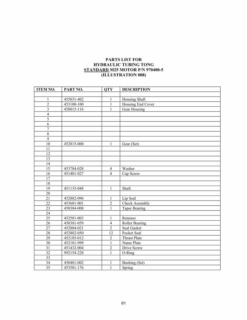
61
PARTS LIST FORHYDRAULIC TUBING TONG
STANDARD M25 MOTOR P/N 970400-5(ILLUSTRATION 008)
ITEM NO. PART NO. QTY DESCRIPTION
1 455031-402 1 Housing Shaft2 453100-100 1 Housing End Cover3 458015-116 1 Gear Housing456789
10 452815-000 1 Gear (Set)1112131415 453784-028 4 Washer16 451401-027 4 Cap Screw171819 451135-048 1 Shaft2021 452882-096 1 Lip Seal22 453681-001 2 Check Assembly23 450384-008 1 Taper Bearing2425 452581-003 1 Retainer26 450381-059 4 Roller Bearing27 452884-021 2 Seal Gasket28 452882-050 12 Pocket Seal29 452185-012 2 Thrust Plate30 452181-999 1 Name Plate31 451432-004 2 Drive Screw32 992154-228 1 O-Ring3334 450481-002 1 Bushing (Set)35 453581-176 1 Spring

62

63

64

65