
OIL AND GAS - roehm.biz
24
OIL AND GAS Clamping technology for crude oil and natural gas industries
Transcript of OIL AND GAS - roehm.biz

OIL AND GASClamping technology for crude oil and natural gas industries

2
CRUDE OIL AND NATURAL GAS - THE ENERGY OF TODAY
RÖHM is the specialist for clamping technology with a wide product range, unrivaled with regard to
variety. This solutions for special requirements are also unlimited in the oil and gas extraction areas.
The crude oil and natural gas industries are still the center
of the worldwide energy production today. The extraction
and further processing of these two raw materials require
top precision and maximum safety. RÖHM products are
characterized by just these properties. In the past years,
RÖHM was able to increasingly adapt the product range to
the most important industries. Sophisticated products allow
the reliable machining of a wide range of workpieces. It
goes without saying that RÖHM has high safety standards.
RÖHM products are specially tailored to the special needs
of this important market. Our strengths not only involve
offering an especially wide range of standard products, but
also to convince our customers with individually developed
special designs.
3
CONTENT
Machining of PipesOverview Pneumatic Front-End Chucks 4
Operation Guide Pneumatic Front-End Chucks 6
Pneumatic Front-End Chucks
LVE 8
LVE-ES 9
LVE-AZ ES 10
LVE-FAZ EC 11
LVE-VZA 12
Centering Chucks KFG 13
Overview Hydraulic Front-End Chucks 14
Operation Guide Hydraulic Front-End Chucks 16
Machining of BushingsSwivel Chucks 18
Special SolutionsStationary Centering and Clamping Unit 20
Center Drive Chuck 21
Machining of Drill BitsSpecial Solutions 22

4
Possible applicationTwo chucks are mounted on the front and rear sides of
the machine spindle. Via a selection switch on our elec-
tronic control unit DF type 525-90 combined with one
pneumatic control unit LSV type 525-91 each, the two
chucks can be used together or separately and also with
different clamping pressures. This combinations make a
high cutting capacity and high turning precision possible
for the end machining of long pipes.
Air-operated self-contained chucks, sizes 400-1000Characteristic for this chuck is a pneumatic piston
integrated in the chuck body for generating the clam-
ping force. To clamp or unclamp the workpiece, the
compressed air is conducted to the pneumatic piston
while the chuck is stationary via the distributor ring and
non-return valve. The pneumatic piston is screwed
to the clamping piston, with which, in turn, the base
jaws are connected via a wedge hook system. An axial
movement of the pneumatic piston therefore causes a
radial movement of the base jaws.
Distributor ringThe distributor ring has the function of transferring
compressed air from the outside into the chuck. This
means that the distributor ring is always stationary, while
the chuck rotates during workpiece machining. It is
therefore mounted to the spindle box, and is therefore
secured against rotating along. Special seals seal the
gap between the distributor ring and chuck during the
clamping operation so that the pressure can be transfer-
red with no problems.
Important: To prevent the sealing ring from being des-
troyed, the pressure may only be transferred when the
chuck is at a standstill.
Control valveThe control valve has the job of securing the com-
pressed air required for clamping in a closed system
throughout machining. It automatically secures that pis-
ton side which is pressurized, whereby the compressed
air of the opposite-lying piston side is unclamped auto-
matically. The valve can be dismounted as a complete
unit and is available as replacement unit.
APPLICATIONOptimal for the end machining of large and long pipes, e.g. for the oil and gasindustry (especially as front and rear chuck).
TYPEPower chuck with integrated pneumatic cylinder and cylindrical centre mount.3-jaw version with serration 90°.
CUSTOMER BENEFITS Extra-large through-hole Can be easily exchanged with manual clamping chuck Compact system dimensions because it is self-contained Unobstructed bore through spindle thanks to omission of the draw tube Flange and bar machining possible without retrofitting
TECHNICAL FEATURES- Clamping and unclamping only when spindle at standstill- Wedge hook system with integrated clamping cylinder- Control valves maintain the clamping pressure during machining- Short clamping cycle thanks to rapid and clamping stoke (optionally)- Permanent monitoring of the clamping pressure while machining (optionally)
Note: Other versions on request: e.g. front-end chucks for compensating clamping,compensating self-contained chucks and chucks that can be converted from selfcentering to compensating.
Included in scope of delivery: Chuck, chuck and jaw mounting screws, slot nuts (without top jaws)
LVE = air-operated, self-contained chuck
90°
PIPE MACHINING:PNEUMATIC FRONT-END CHUCKS
The pneumatic front-end chucks are optimally suited for machining the ends of pipes, especially large
and long pipes like the ones used for extracting crude oil or natural gas. For this, a chuck is mounted
to the front and rear sides of the machine spindle. This combination allows large chipcutting perfor-
mance at high turning precision.

5
Control systemThe clamping safety mainly depends on the leak-tight-
ness of the closed pneumatic chamber. A pressure drop
during machining causes a reduction in the clamping
force.
The „RÖHM control system“ is used to control the pres-
sure of the closed pneumatic chamber. If the pressure
falls below a defined minimum level, a spring-loaded pin
attached to the rear side of the chuck moves out to the
rear.
At the same height as the pin, a contactless inducti-
ve probe is fastened at a certain radial distance. If the
extended pin moves through the magnetic field of the
probe, an electrical pulse is triggered, which can be used
to shut the machine down.
Wedge hook systemThe axial piston force is transferred and transmitted into
the radial jaw force via the proven wedge hooks. The
large force transfer surfaces guarantee a long service life
and a sustainably high clamping precision.These features
apply both to the chuck with normal jaw stroke as well as
to chucks with rapid and gripping jaw movements.
Components LVE
1. Body
2. Base jaw
3. Piston
4. Protective bush
5. Intermediate washer
6. Piston plate
7. Flange
8. Distributor ring
9. Seal
10. T-Nut
11. Air-vent screw
12. Control valve
13. Jaw fixing screws
14. Chuck fixing screws
11
14
13
4
3
9
7
82
1
5
6
10
12
Control voltage 24 V
Connection R 1/2" inside thread
Weight approx. 3 kg
Dimensions: 280x250x100 mm
(WxHxD)
Item no.: 426560
PNEUMATIC CONTROL UNIT
With dual foot switch, wired, 6m cable
Control voltage 24 V
Dimensions: 300x300x120 mm
(WxHxD)
Width with plug: 340 mm
Item no.:426482 without pressure monitoring426464 with pressure monitoring
CONTROL UNIT FOR DUAL CHUCKS
PIPE MACHINING:PNEUMATIC FRONT-END CHUCKS

6
OPERATION GUIDE LVE
EC
TYPE LVE LVE-ES
Description - Pneumatic front-end chuck
- Concentric clamping
- Pneumatic front-end chuck
- Concentric clamping
- With rapid stroke and clam-
ping stroke
Page 8 9
Characteristics
Machining situation: Bent pipeCentering via centering chuck
Machining situation: Bent pipeCentering by front-end chuck
Machining situation: Exactly straight pipeNo centering required
pneumatic
hydraulicrapid stroke and
clamping stroke
with
compensation
centeringspring
low-maintenance
(Easy Care)
retractable clamping
arms for pre-centering
ring required
g y
ng via centering chuck

7
LVE-AZ ES LVE-FAZ EC LVE-VZA Centering chuck KFG
- Pneumatic front-end
chuck
- Concentric clamping or
with compensation
- With rapid stroke and
clamping stroke
- Front-end chuck
- Clamping with springs,
pneumatic release
- Concentric clamping or
with compensation
- Low-maintenance design
- Pneumatic/spring-opera-
ted front-end chuck
- Concentric clamping or
with compensation
- Retractable clamping
arms for pre-centering the
workpiece
- Pneumatic angle lever
chuck
- Concentric clamping
- Integrated flapper with
stroke inquiry
10 11 12 13
EC
front-end chuck
with centering
ideally
suited
suitedexactly
straight pipe
rear-end
chuckbent pipe
front-end
chuckcentering chuck
fr
wben
ac
straig
nt
exa
ben
8
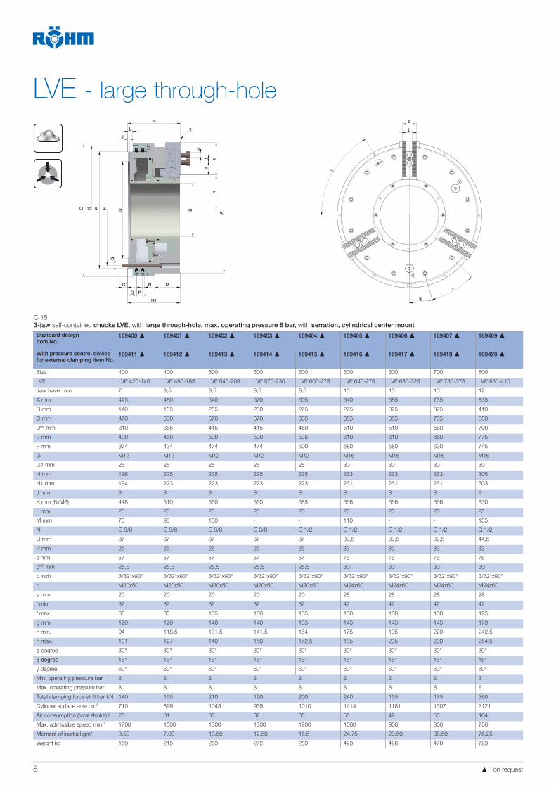
LVE - large through-hole
L
J
H
G1 N
O P
M
H1
B
h
f
d
e
g
A
F
G
EKC
c
D
b
a
ß
α
γ
C 15
3-jaw self-contained chucks LVE, with large through-hole, max. operating pressure 8 bar, with serration, cylindrical center mount
Standard designItem No.
169400 169401 169402 169403 169404 169405 169406 169407 169409
With pressure control device for external clamping Item No.
169411 169412 169413 169414 169415 169416 169417 169418 169420
Size 400 400 500 500 600 600 600 700 800
LVE LVE 420-140 LVE 480-185 LVE 540-205 LVE 570-230 LVE 600-275 LVE 640-275 LVE 680-325 LVE 730-375 LVE 830-410
Jaw travel mm 7 8,5 8,5 8,5 8,5 10 10 10 12
A mm 425 480 540 570 605 640 685 735 835
B mm 140 185 205 230 275 275 325 375 410
C mm 470 530 570 570 605 685 685 735 850
DH6 mm 310 365 415 415 450 510 510 560 700
E mm 400 460 500 500 535 610 610 660 775
F mm 374 434 474 474 500 580 580 630 745
G M12 M12 M12 M12 M12 M16 M16 M16 M16
G1 mm 25 25 25 25 25 30 30 30 30
H mm 196 225 225 225 225 263 263 263 305
H1 mm 194 223 223 223 223 261 261 261 303
J mm 8 8 8 8 8 8 8 8 8
K mm (6xM8) 448 510 550 550 585 666 666 666 830
L mm 20 20 20 20 20 20 20 20 25
M mm 70 90 100 - - 110 - - 155
N G 3/8 G 3/8 G 3/8 G 3/8 G 1/2 G 1/2 G 1/2 G 1/2 G 1/2
O mm 37 37 37 37 37 39,5 39,5 39,5 44,5
P mm 26 26 26 26 26 33 33 33 33
a mm 57 57 57 57 57 75 75 75 75
bH7 mm 25,5 25,5 25,5 25,5 25,5 30 30 30 30
c inch 3/32“x90° 3/32“x90° 3/32“x90° 3/32“x90° 3/32“x90° 3/32“x90° 3/32“x90° 3/32“x90° 3/32“x90°
d M20x50 M20x50 M20x50 M20x50 M20x50 M24x60 M24x60 M24x60 M24x60
e mm 20 20 20 20 20 28 28 28 28
f min. 32 32 32 32 32 42 42 42 42
f max. 85 85 105 100 105 100 100 100 125
g mm 120 120 140 140 135 145 145 145 173
h min. 94 118.5 131.5 141.5 164 175 195 220 242.5
h max. 101 127 140 150 172,5 185 205 230 254.5
degree 30° 30° 30° 30° 30° 30° 30° 30° 30°
15° 15° 15° 15° 15° 15° 15° 15° 15°
y degree 60° 60° 60° 60° 60° 60° 60° 60° 60°
Min. operating pressure bar 2 2 2 2 2 2 2 2 3
Max. operating pressure bar 8 8 8 8 8 8 8 8 8
Total clamping force at 6 bar kN 140 155 210 190 200 240 155 175 360
Cylinder surface area cm2 710 899 1045 939 1010 1414 1181 1307 2121
Air consumption (total stroke) l 20 31 36 32 35 58 49 55 104
Max. admissible speed min-1 1700 1500 1300 1300 1200 1000 900 800 750
Moment of inertia kgm2 3,50 7,00 10,50 12,50 15,5 24,75 29,50 38,50 76,25
Weight kg 150 215 263 272 289 423 426 470 723
on request

9
LVE ES - large through-hole, with rapid and clamping jaw movements
J
L
H
d
fe
gh
B A
MNG1
O P
H1
G
DE FKC
c b
a
ß
α
γ
C 15
3-jaw self-contained chucks LVE, with rapid and clamping jaw movements, with large through-hole, external chucking, max. operating pressure 8 bar, with serration, cylindrical center mountStandard designItem No.
169422 169423 169424 169425 169426 169427 169428 169429 169431
With pressure control de-vice for external clamping Item No.
169433 169434 169435 169436 169437 169438 169439 169440 169442
Size 400 400 500 500 600 600 600 700 800
LVE LVE 470-140 ES LVE 490-185 ES LVE 570-205 ES LVE 570-230 ES LVE 600-275 ES LVE 640-275 ES LVE 680-325 ES LVE 730-375 ES LVE 850-410 ES
Jaw travel mm 19 25,4 25,4 25,4 25,4 25,4 25,4 25,4 25,4
Rapid movement mm 12 16.9 16,9 16.9 16.9 16,9 16.9 16.9 14,9
Clamping movement mm 7 8.5 8,5 8.5 8.5 8,5 8.5 8.5 10,5
A mm 470 490 570 570 605 645 685 735 850
B mm 140 185 205 230 275 275 325 375 410
C mm 470 530 570 570 605 685 685 735 850
DH6 mm 310 365 415 415 450 510 510 560 700
E mm 400 460 500 500 535 610 610 660 775
F mm 374 434 474 474 509 580 580 630 745
G M12 M12 M12 M12 M12 M16 M16 M16 M16
G1 mm 25 25 25 25 25 30 30 30 30
H mm 240 282 282 282 282 308 308 308 322
H1 mm 238 280 280 280 280 306 306 306 320
J mm 8 8 8 8 8 8 8 8 8
K mm (6xM8) 448 510 550 550 585 666 666 716 830
L mm 20 20 20 20 20 20 20 20 25
M mm - 140 100 - - 150 - - -
N G 3/8 G 3/8 G 3/8 G 3/8 G 3/8 G1/2 G 1/2 G 1/2 G 1/2
O mm 37 37 37 37 37 39,5 39,5 39,5 44,5
P mm 26 26 26 26 26 33 33 33 33
a mm 57 57 57 57 57 75 75 75 75
bH7 mm 25,5 25,5 25,5 25,5 25,5 30 30 30 30
c inch 3/32“x90° 3/32“x90° 3/32“x90° 3/32“x90° 3/32“x90° 3/32“x90° 3/32“x90° 3/32“x90° 3/32“x90°
d M20x50 M20x50 M20x50 M20x50 M20x50 M24x60 M24x60 M24x60 M24x60
e mm 20 20 20 20 20 28 28 28 28
f min. 32 32 32 32 32 42 42 42 42
f max. 80 80 95 95 90 95 95 95 120
g mm 112 112 130 130 125 140 140 140 170
h min. 126 132.6 142,1 154.6 177.1 182,6 202.6 227.6 234,6
h max. 145 158 167,5 180 202.5 208 228 253 260
degree 30° 30° 30° 30° 30° 30° 30° 30° 30°
degree 15° 15° 15° 15° 15° 15° 15° 15° 15°
degree 60° 60° 60° 60° 60° 60° 60° 60° 60°
Min. operating pressure bar 2 2 2 2 2 2 2 2 3
Max. operating pressure bar 8 8 8 8 8 8 8 8 8
Total clamping force at 6
bar kN
120 150 210 170 180 185 180 200 325
Cylinder surface area cm2 700 862 1024 895 958 1203 1181 1307 2121
Air consumption (totalstroke) l 32 42 50 45 46 58 57 63 113
Max. admissible speed min-1 1500 1300 1200 1200 1100 900 800 750 750
Moment of inertia kgm2 6,50 8,75 15,50 15,00 19,00 30,5 35,25 45,75 84,50
Weight kg 200 267 348 334 356 515 505 554 785
on request

10
LVE-AZ ES
on request
LVE-AZ ES 570-220 KK15
LVE-AZ ES 650-275 KK15 - KK20
LVE-AZ ES 760-375 KK20
Item no. 169519 169520 169521
Jaw stroke mm 25,4 25,4 25,4
Rapid/clamping mm 15,9/9,5 15,9/9,5 15,9/9,5
Min./max. Operating pressure bar 2/8 2/8 3/8
Gripping force concentric kN at 6bar 155 180 240
Gripping force comp. kN at 6bar 75 85 100
Max. Speed min-1 1200 1000 750
-Z-/-A- Cylinder area cm² 1015/520 1360/680 1620/680
-Z-/-A- Air consumption l 50/70 67/90 80/100
Weight kg 535 730 925
Moment of inertia kgm² 25,00 45,00 80,00
A mm 570 650 760
B mm 220 275 375
C mm 570 685 780
DH6 mm 415 510 590
E mm 500 615 710
F Pitch diameter mm 470 555 640
G/G1 mm M20/30 (9x) M20/35 (9x) M20/35 (12x)
H mm 382 382 382
H1/H2 mm 375/417 375/(417) 422 375/422
J mm 10 10 10
K Pitch diameter (12x30°) M8-20 mm 555 670 765
L mm 10 10 10
M mm - 220 220
N Pneumatic connection G 3/4 G 3/4 G 3/4
O mm 25 25 25
P mm 22 22 22
a mm 61 75 75
bH7 mm 25,5 30 30
c Serration inch 3/32"x90° 3/32"x90° 3/32"x90°
d Screw DIN 912-12.9 mm M20x55 M24x65 M24x65
e min. 20 25 25
f min./max. 32/90 40/95 40/95
g mm 128 140 140
h min./max. 154,1/179,5 179,4/205,0 232,1/257,5
a degree 22,5° 25° 20°
b degree 22,5° 25° 20°
g degree 30° 30° 30°

11 on request
LVE-FAZ EC
LVE-FAZ EC 675-275 LVE-FAZ EC 825-395 LVE-FAZ EC 1000-570
Item no. 169516 169517 169518
Jaw stroke mm 18,0 22,0 22,0
Min./max. Opening pressure bar 3/5 5/8 5/8
Max. Gripping force kN30/60/90
(3/6/9 Federn)
90/135/180
(6/9/12 Federn)
90/135/180
(6/9/12 Federn)
Max. Speed min-1 1000 750 450
Cylinder area cm2 2170 2890 3790
Air consumption l 50 60 80
Weight kg 525 900 1150
Moment of inertia kgm² 35,00 95,00 190,00
A mm 675 825 1000
B mm 275 395 570
C mm 750 900 1075
DH6 mm 510 700 870
E mm 680 830 1000
F Pitch diameter (12x30°) mm 640 785 960
G/G1 mm M12/25 M16/30 M16/30
H mm 298 320 320
H1 mm 290 310 310
J mm 8 10 10
K Pitch diameter (12x30°) M8-20
mm730 880 1055
L mm 20 20 20
M mm 205 225 225
N Pneumatic connection inch G 3/4 G 3/4 G 3/4
O mm 25 25 25
a mm 60 80 80
bH7 mm 25,5 30 30
c Serration inch 3/32"x90° 3/32"x90° 3/32"x90°
d Screw DIN 912-12.9 mm M20x45 M24x65 M24x65
e min. 14 28 28
f min./max. 32/115 40/105 40/105
g mm 145 155 155
h min./max. mm 184,5/202,5 238,0/260,0 328,0/350,0
a degree 30° 30° 30°
b degree 15° 15° 15°
g degree 30° 30° 30°
EC

12
LVE-VZA
on request
LVE-VZA 760-275 LVE-VZA 860-375 LVE-VZA 960-475
Item no. 169522 169523 169514
Clamping jaw stroke mm 20 20 20
+/- Compensation mm ±5 ±6 ±6
Centering jaw stroke mm 38,5 38,5 38,5
Min./max. Opening pressure bar 4/8 4/8 4/8
Max. Gripping force 3/6/9/12 Springs kN 40/80/120 40/80/120 40/80/120/160
Max. Centering pressure bar 3 3 3
Max. Centering force kN at 3 bar 85 100 120
Max. Speed min-1 750 500 450
Min. Air consumption opening l 50 75 115
Air consumption center. l 80 95 110
Weight kg 1250 1475 1705
Moment of inertia kgm² 107,50 170,00 252,50
A mm 760 860 960
B mm 275 375 475
C mm 900 1000 1100
DH6 mm 415 560 680
E mm 825 925 1025
F Pitch diameter (9x40° / 12x30°) mm 540 640 740
G/G1 mm M24/-- M24/-- M24/--
H mm 496 496 496
H1/H2 mm 490/580 490/580 490/580
J mm 12 12 12
K Pitch diameter (12x30°) M8-20 mm 885 985 1085
L mm 70 70 70
M/M1 mm 172,5/297,5 172,5/297,5 172,5/297,5
N Pneumatic connection inch G 3/4 G 3/4 G3/4
O mm 87,5 87,5 87,5
P mm 22 22 22
Q min./max. 50/195 50/195 50/195
a/a1 mm 80/60 80/60 80/60
b/b1H7 mm 30/22 30/22 30/22
c Serration inch 3/32"x90° 3/32"x90° 3/32"x90°
c1g6 mm 22 22 22
d / d1 Screw DIN 912-12.9 mm M24x60 / M16x60 M24x60 / M16/60 M24x60 / M16/60
e min./max. mm 20/70 20/70 20/70
f / f1 mm 42 / 50 42/50 42/50
g mm 175 175 175
h min./max. mm 190,0/210,0 240,0/260,0 290,0/310,0
h1 min./max. mm 175,5/214,0 225,5/264,0 275,5/314,0
g degree 30° 30° 30°
13 on request
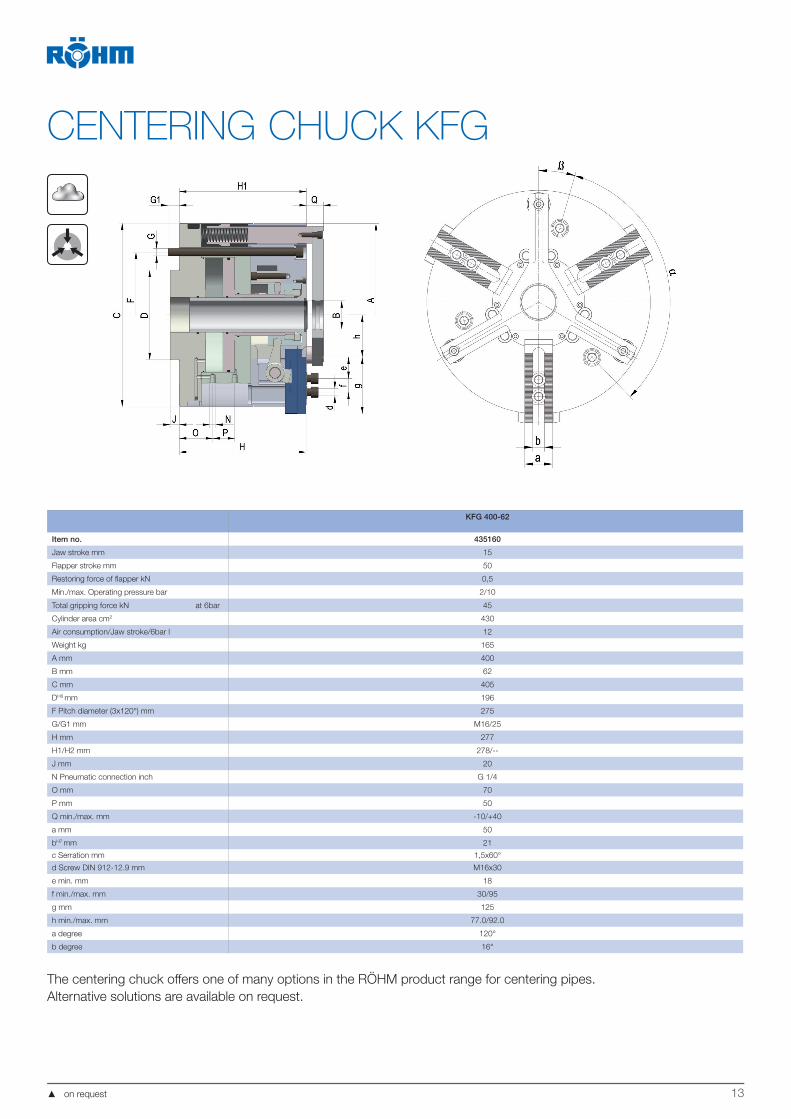
CENTERING CHUCK KFG
KFG 400-62
Item no. 435160
Jaw stroke mm 15
Flapper stroke mm 50
Restoring force of flapper kN 0,5
Min./max. Operating pressure bar 2/10
Total gripping force kN at 6bar 45
Cylinder area cm2 430
Air consumption/Jaw stroke/6bar l 12
Weight kg 165
A mm 400
B mm 62
C mm 405
DH6 mm 196
F Pitch diameter (3x120°) mm 275
G/G1 mm M16/25
H mm 277
H1/H2 mm 278/--
J mm 20
N Pneumatic connection inch G 1/4
O mm 70
P mm 50
Q min./max. mm -10/+40
a mm 50
bH7 mm 21
c Serration mm 1,5x60°
d Screw DIN 912-12.9 mm M16x30
e min. mm 18
f min./max. mm 30/95
g mm 125
h min./max. mm 77.0/92.0
a degree 120°
b degree 16°
The centering chuck offers one of many options in the RÖHM product range for centering pipes.
Alternative solutions are available on request.

14
PIPE MACHINING: HYDRAULIC FRONT-END CHUCKS
The hydraulic front-end chucks are optimally suited for machining the ends of pipes, especially large
and long pipes like the ones used for extracting crude oil or natural gas. For this, one chuck is moun-
ted to the front and one to the rear side of the machine spindle. This combination allows large chip-
cutting performance at high turning precision.
Actuation HVE-IZDuring pipe machining, the clamping system is decoupled
from the supply via relief valves. A pressure accumulator
ensures a sufficient resupply. A sensor system detects
any drop in pressure. The HVE-IZ chuck is actuated via
injection cylinders. These are arranged radially with respect
to the rotary axis.
Actuation HVE-EKThe HVE-EK chuck has stationary actuation, which is
decoupled from the rotating system during machining. The
stationary actuating unit is located between the chuck and
spindle box, and is separated from the rotating compo-
nents.
Setup and mode of operationRÖHM offers two concepts for hydraulically actuating the
front-end chucks:
HVE-IZ: Actuation is done via injection cylinder
HVE-EK: Stationary actuation which is decoupled during
rotation
The two variants can be used both with centric clamping
as well as clamping with compensation. For this, the floa-
ting clamping claw disc is merely fastened with two bolts,
or released for compensating clamping. The clamping jaws
with rapid and clamping stroke ensure large strokes with
short stroke times. The hydraulically operated chucks are
available with central lubrication.
The individual clamping chucks are supplied either
via a distributor flange for each chuck, on the front and
rear side of the spindle box
via a distributor flange on the rear side of the spindle
box and supply of the front-end chuck via the oil supply
pipe or
via a distributor flange on the front side of the spindle
box and supply of the rear-end chuck via the oil supply
pipe
To couple the injection cylinder, it is necessary to exactly
position the machine spindle. Here, the injection cylinder
is monitored by limit switches. Decoupling is done without
pressure. The generously dimensioned interface from the
stationary to rotating areas allows short switching times, as
little as one second per clamping function.
15
PIPE MACHINING:HYDRAULIC FRONT-END CHUCKS
1
2
3
4
5
6
35
8
7
4
2
1
14
15
16
12
13
9
1011
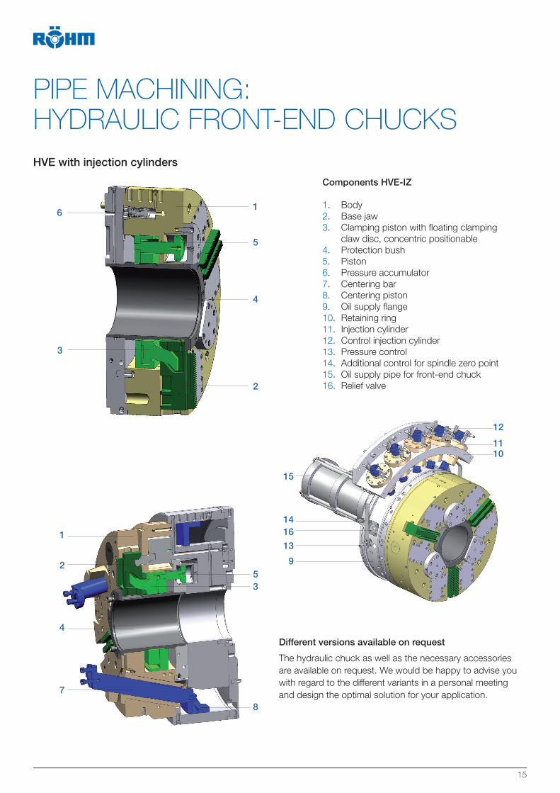
Components HVE-IZ
1. Body
2. Base jaw
3. Clamping piston with floating clamping
claw disc, concentric positionable
4. Protection bush
5. Piston
6. Pressure accumulator
7. Centering bar
8. Centering piston
9. Oil supply flange
10. Retaining ring
11. Injection cylinder
12. Control injection cylinder
13. Pressure control
14. Additional control for spindle zero point
15. Oil supply pipe for front-end chuck
16. Relief valve
HVE with injection cylinders
The hydraulic chuck as well as the necessary accessories
are available on request. We would be happy to advise you
with regard to the different variants in a personal meeting
and design the optimal solution for your application.
Different versions available on request
16
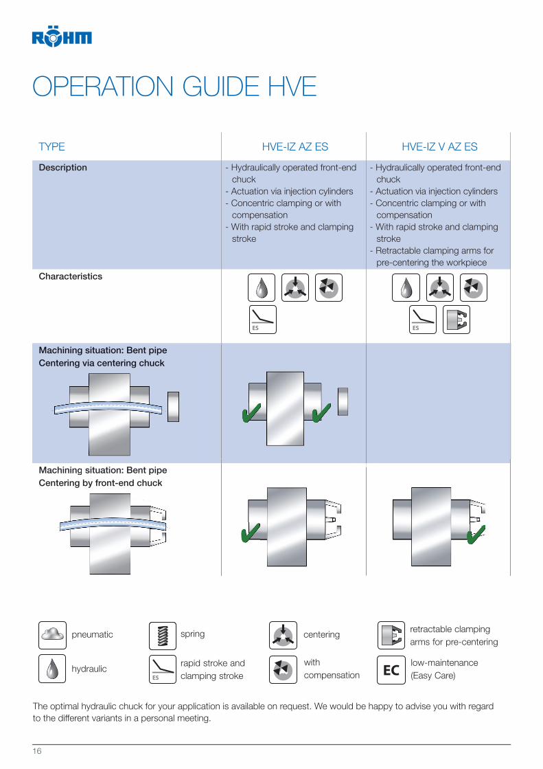
OPERATION GUIDE HVE
TYPE HVE-IZ AZ ES HVE-IZ V AZ ES
Description - Hydraulically operated front-end
chuck
- Actuation via injection cylinders
- Concentric clamping or with
compensation
- With rapid stroke and clamping
stroke
- Hydraulically operated front-end
chuck
- Actuation via injection cylinders
- Concentric clamping or with
compensation
- With rapid stroke and clamping
stroke
- Retractable clamping arms for
pre-centering the workpiece
Characteristics
Machining situation: Bent pipeCentering via centering chuck
Machining situation: Bent pipeCentering by front-end chuck
pneumatic
hydraulicrapid stroke and
clamping stroke
with
compensation
centeringspring
low-maintenance
(Easy Care)
retractable clamping
arms for pre-centering
The optimal hydraulic chuck for your application is available on request. We would be happy to advise you with regard
to the different variants in a personal meeting.
Centering by front-end chuckC i b f d h k
Machining situation: Bent pipeCentering via centering chuck
Machining situation: Bent pipeC i b f d h k
EC

17
HVE-EK AZ ES HVE-EK V AZ ES Centering chuck
- Hydraulically operated front-end
chuck
- Stationary actuation
- Concentric clamping or with com-
pensation
- With rapid stroke and clamping
stroke
- Hydraulically operated front-end
chuck
- Stationary actuation
- Concentric clamping or with com-
pensation
- With rapid stroke and clamping
stroke
- Retractable clamping arms for pre-
centering the workpiece
From a wide range of centering op-
tions, we will select the right centering
chuck for your machining application
front-end chuck
with centering
ideally
suited
suitedexactly
straight pipe
rear-end
chuckbent pipe
front-end
chuckcentering chuck

18
BUSHING MACHINING: SWIVEL CHUCKS
Swivel chucks are optimally suited for machining bushings or connection pieces on both sides. With
the swivel axis, which lies 90° relative to the rotary axis, the workpiece is brought into the respective
machining positions fully automatically.
Setup and mode of operationThe swivel chuck has a closed chuck body, in which a
ring, which can be swiveled by 180°, is supported with two
gear racks. This serves as a clamping ring and has three
concentric clamping jaws and three compensating clam-
ping jaws. The clamping ring is fixed laterally on the outer
diameter via two indexing bolts. The compact design of the
chuck ensures a favorable ratio of workpiece diameter to
chuck size and weight.
Machining in one setup offers two decisive advantages:
Maximum axial precision
Minimum setup effort
ActuationThe swivel chucks are supplied with the required energy
via a 9- or 11-way oil distributor. The oil distributors are
located at the end of the spindle. The matching oil distribu-
tors and hydraulic units are available on request.
ControlA check is done via a feedback cylinder on the hydraulic
unit in the swivel positions 0° and 180° and during locking.
Even if there is a pressure drop, the clamping as well as
the locking are maintained by means of safety valves.

19
HSFZ 560 HSFZ 710 HSFZ 860
Idem no. 439237 439022 439023
Size mm 560 710 860
Total stroke per jaw mm 8 10 10
Recommended clamping stroke per jaw mm 6 7 7
Clamping reserve per jaw mm 2 3 3
Operating pressure bar 45 45 45
Total gripping force kN at 45 bar 130 159 159
Max. Speed min-1 1000 800 650
Weight kg 360 650 920
Moment of inertia kgm² 14 38 86
A mm 560 710 860
B mm 216 280 430
C mm 376 475 550
D mm 312 395 470
Spindle connection DIN 55021 size 15 DIN 55026 size 11 DIN 55026 size 20
E mm 410 280 520
F Pitch diameter mm 330 (6x60°) 235 (6x60°) 463,6 (12x30°)
G / G1 mm M24 / 36 (4x) M20 / 30 (6x) M24 / 36 (8x)
H mm 21 21 24
Xmax
Max. Work piece diameter mm 160 220 370
Ymax
Max. Interference circle diameter mm 405 516 666
Max. Work piece length Z, depending on
Work piece diameter X
(at centric operation) mmZ = √Y² - X²
The power-operated swivel chuck KSFZ is suitable as an
alternative clamping solution for bushings. The workpiece
is clamped at four points via two concentric clamping jaws.
The clamping jaws are actuated via a clamping cylinder on
the end of the spindle. Concentric clamping swivel chucks
are available from a diameter of 210 mm to 820 mm and
according to the individual wishes of the customer.
POWER-OPERATED SWIVEL CHUCK KSFZ
Another option for machining bushings is to use a LVE or LVE-ES front-end chuck. With this, the workpiece can be ma-
chined in two setups. The corresponding data can be found on pages 8 and 9.
PNEUMATIC FRONT-END CHUCK LVE
20
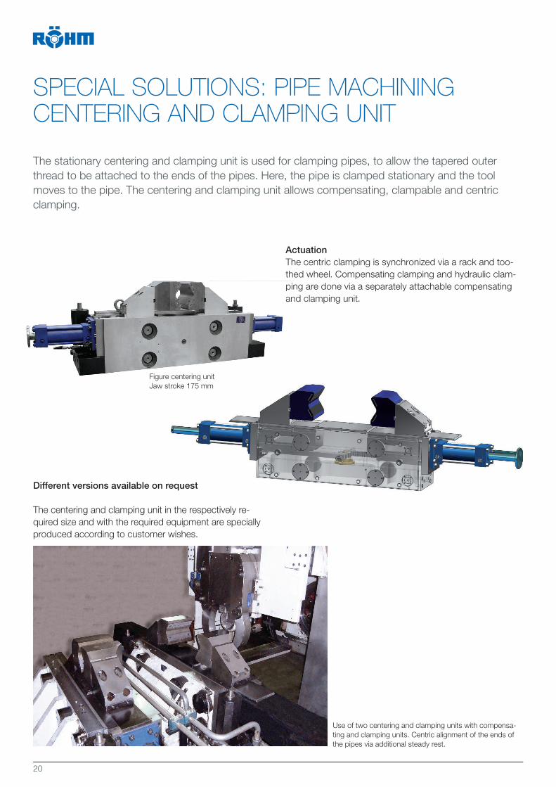
SPECIAL SOLUTIONS: PIPE MACHININGCENTERING AND CLAMPING UNIT
The stationary centering and clamping unit is used for clamping pipes, to allow the tapered outer
thread to be attached to the ends of the pipes. Here, the pipe is clamped stationary and the tool
moves to the pipe. The centering and clamping unit allows compensating, clampable and centric
clamping.
ActuationThe centric clamping is synchronized via a rack and too-
thed wheel. Compensating clamping and hydraulic clam-
ping are done via a separately attachable compensating
and clamping unit.
th
pin
an
Figure centering unit
Jaw stroke 175 mm
Different versions available on request
The centering and clamping unit in the respectively re-
quired size and with the required equipment are specially
produced according to customer wishes.
Use of two centering and clamping units with compensa-
ting and clamping units. Centric alignment of the ends of
the pipes via additional steady rest.
21
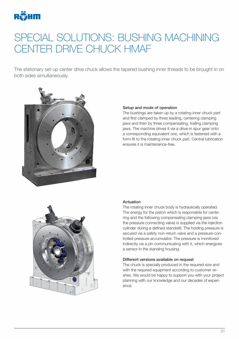
SPECIAL SOLUTIONS: BUSHING MACHINING CENTER DRIVE CHUCK HMAF
The stationary set-up center drive chuck allows the tapered bushing inner threads to be brought in on
both sides simultaneously.
Setup and mode of operationThe bushings are taken up by a rotating inner chuck part
and first clamped by three leading, centering clamping
jaws and then by three compensating, trailing clamping
jaws. The machine drives it via a drive-in spur gear onto
a corresponding equivalent one, which is fastened with a
form-fit to the rotating inner chuck part. Central lubrication
ensures it is maintenance-free.
ActuationThe rotating inner chuck body is hydraulically operated.
The energy for the piston which is responsible for cente-
ring and the following compensating clamping jaws (via
the pressure connecting valve) is supplied via the injection
cylinder during a defined standstill. The holding pressure is
secured via a safety non-return valve and a pressure-con-
trolled pressure accumulator. The pressure is monitored
indirectly via a pin communicating with it, which energizes
a sensor in the standing housing.
Different versions available on requestThe chuck is specially produced in the required size and
with the required equipment according to customer wi-
shes. We would be happy to support you with your project
planning with our knowledge and our decades of experi-
ence.

22
SPECIAL SOLUTIONS: DRILL BIT MACHINING
RÖHM offers individual special solutions for machining drill bits. Thanks to numerous, often very dif-
ferent contours, which often occur in crude oil and natural gas extraction, specially designed chucks
are necessary for machining drill bits. Extreme precision as well as a high degree of safety and mo-
dern production are top priorities. The workpieces can be clamped in on the head side. This allows
the thread to be machined.
Drill bit requirementsThe drill bit must meet numerous requirements for drilling.
In the case of crude oil or natural gas extraction, drilling is
done both on land as well as on the sea floor. The drill bit
must penetrate through different layers of rock. This not
only requires high demands on the material of the head,
but also extremely exact contours. The numerous fast
movements which the head must execute during drilling
machining require considerable precision, which can only
be achieved with exact dimensions and shape precision.
JawsThe perfect adjustment of the chuck to the workpiece to
be machined also requires the jaws to be adjusted. A wide
range of standard jaws and different specially designed
jaws round off the product range for machining drill bits.
Different versions available on requestPlease request clamping chucks for machining drill bits for
the crude oil and natural gas industry directly from RÖHM.
The chuck is produced according to the workpiece requi-
rements.

23

RÖHM GmbHHeinrich-Röhm-Straße 50
89567 Sontheim/Brenz
Germany
Tel +49 7325 16 0
Fax +49 7325 16 510
www.roehm.biz Id.-Nr. 1242310/0819