OHIO University Mechanical Engineering Conceptual … rollers subsystem included rollers in Figure...
41
OHIO University Mechanical Engineering Conceptual Design Report GOOD EARTH BEAN SHELLER Team Green Bean Chris Allen Mark Hritz Andrew Janosik Dan Knuckles Sean Mefferd Michael Seiser 1/13/2012
Transcript of OHIO University Mechanical Engineering Conceptual … rollers subsystem included rollers in Figure...
OHIO University Mechanical Engineering Conceptual Design Report
GOOD EARTH BEAN SHELLER
Team Green Bean
Chris Allen
Mark Hritz
Andrew Janosik
Dan Knuckles
Sean Mefferd
Michael Seiser
1/13/2012

Page 1 of 22
1.0 Concept Generation
1.1 Problem Statement for Concept Generation
Due to the gap between small gardens and large commercial farms, there is a need for automated
mechanical systems to perform time consuming tasks on medium scale farms. Farms of this size
include those run by independent farmers or not-for-profit farms that operate on a volunteer
basis. In particular, there is a need for a machine that will accept a variety of bean pods as input
and produce shelled beans as output, with little to no work required by the operator.
The first step in concept generation was to identify the methods currently employed to
accomplish this task. The black box model was then used as a basis for each member of the team
to generate various complete system concepts. Upon identifying successful methods to remove
beans from pods, the black box was designated as a complete system that takes bean pods in and
outputs shelled beans. Each member of the team is required to define their complete system
including all subsystems. Circular brainstorming was then employed to identify the strengths,
weaknesses, and possible opportunities for improvement of each concept.
1.2 Patent Search
The patent search performed by the group resulted in a large variety of concepts that have been
previously designed. The patented concepts varied in scale and method. The patents also varied
in age, with some dating back to the mid 1800’s. The patents were sorted by method of operation
and several of the most relevant patents to our concept design are shown below.
1.2.1 Roller Method Patents
The first group of patents shown use the “roller method” for de-shellling beans. In general,
patents for this method were the oldest. Also, these patented concepts are for a small scale
operation. Figure 1.1 shows a patented roller method “pea sheller.”
[The rest of this page intentionally left blank]

Page 2 of 22
Figure 1.1: Roller Method [1]
The concept shown above is from 1864. It uses a hand crank to drive the main two rollers as
well as a conveyor feed system. The conveyor is driven by a pulley system. The gap between
the two rollers can be easily adjusted with a screw mechanism at the top of the machine. The
beans are separated from their pods after they move through the rollers. This method of
separation is different from most of the other roller method designs. The most typical method of
separation is to have the peas stay on the feed side of the rollers while the pods move to the other
side. An additional patent is shown below in Figures 1.2 and Figure 1.3.
Figure 1.2: Double Roller Mechanism [2]

Page 3 of 22
In Figure 1.2 and Figure 1.3, two sets of rollers are used to de-shell the beans. When the beans
go through the first set of rollers, they are sliced open by the bottom roller. The top roller has
ridges on it to help pull the beans through. This process is shown in Figure 1.2. The next set of
rollers are placed close together so that the pods get pulled through but the beans are left behind
as shown in Figure 1.2.
Figure 1.3: “Pre-slicing” method [2]
Another common design of roller systems is to have some type of gripping features on the
rollers. One patent that incorporates this design is shown in Figure 1.4.
Figure 1.4: Sheller with Studded Rollers [3]
This patent is for a small scale sheller, and has two very small studded rollers.
Page 4 of 22
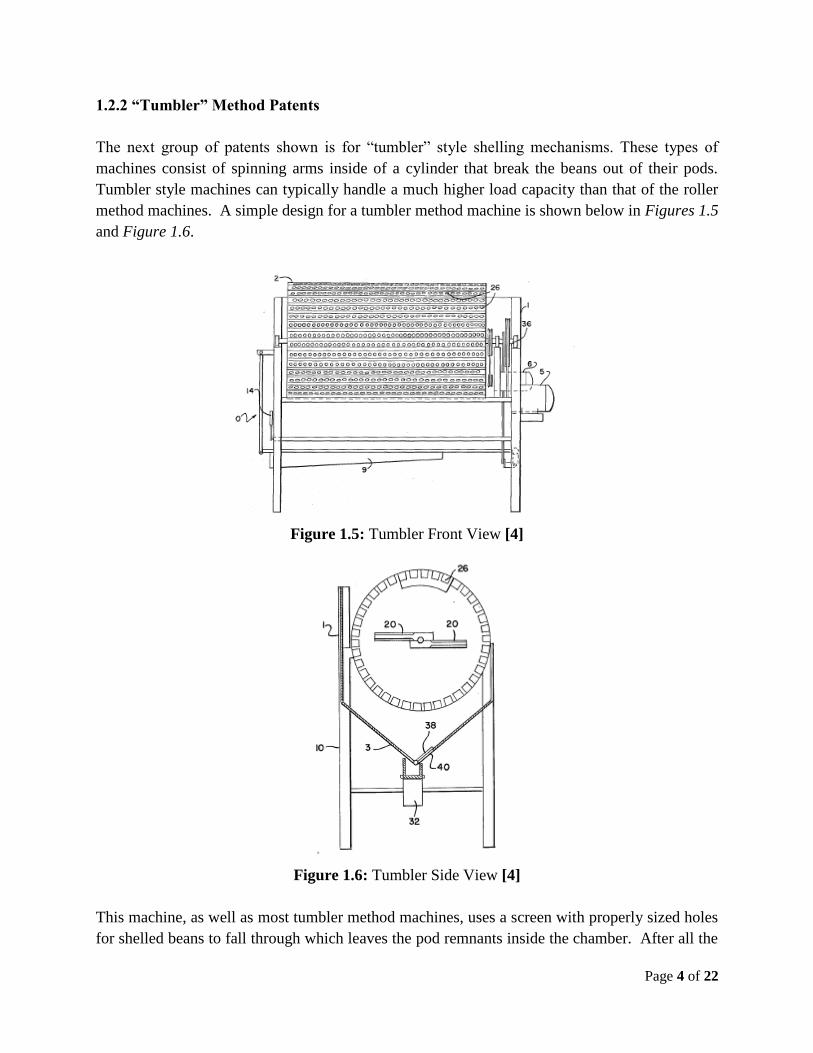
1.2.2 “Tumbler” Method Patents
The next group of patents shown is for “tumbler” style shelling mechanisms. These types of
machines consist of spinning arms inside of a cylinder that break the beans out of their pods.
Tumbler style machines can typically handle a much higher load capacity than that of the roller
method machines. A simple design for a tumbler method machine is shown below in Figures 1.5
and Figure 1.6.
Figure 1.5: Tumbler Front View [4]
Figure 1.6: Tumbler Side View [4]
This machine, as well as most tumbler method machines, uses a screen with properly sized holes
for shelled beans to fall through which leaves the pod remnants inside the chamber. After all the
Page 5 of 22
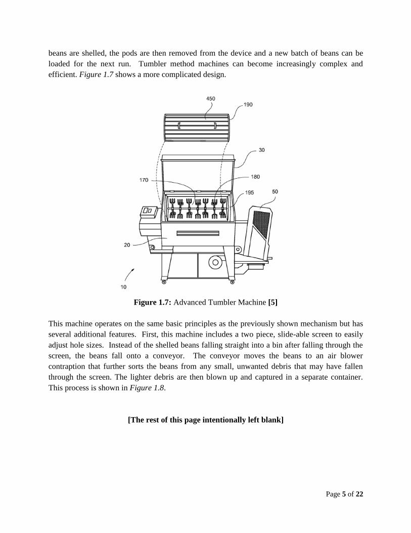
beans are shelled, the pods are then removed from the device and a new batch of beans can be
loaded for the next run. Tumbler method machines can become increasingly complex and
efficient. Figure 1.7 shows a more complicated design.
Figure 1.7: Advanced Tumbler Machine [5]
This machine operates on the same basic principles as the previously shown mechanism but has
several additional features. First, this machine includes a two piece, slide-able screen to easily
adjust hole sizes. Instead of the shelled beans falling straight into a bin after falling through the
screen, the beans fall onto a conveyor. The conveyor moves the beans to an air blower
contraption that further sorts the beans from any small, unwanted debris that may have fallen
through the screen. The lighter debris are then blown up and captured in a separate container.
This process is shown in Figure 1.8.
[The rest of this page intentionally left blank]

Page 6 of 22
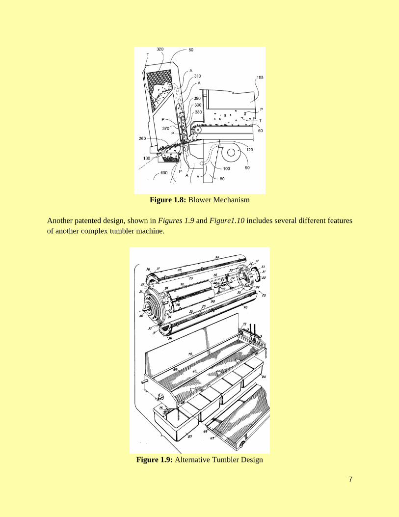
Figure 1.8: Blower Mechanism [5]
Another patented design, shown in Figure 1.9, includes several different features of another
complex tumbler machine.
Figure 1.9: Alternative Tumbler Design [6]

Page 7 of 22
The first unique feature in this design is that the cylindrical drum turns as rows of beaters turn.
The patent calls out a beaters to drum rotational speed ratio of 5:1. The drum spins in the
opposite direction as the beaters. Another different feature of this design is that the beaters have
free spinning forks at the ends. The patent calls out several different types of interchangeable
tips that can be used at the ends of the beaters for different applications. This design also
includes a method for further sorting beans from hull debris after the screen of the main drum.
The design uses offset shafts on pulleys, to make two sets of screens vibrate. The vibration
motion moves the beans over the screens and sorts them accordingly into collection buckets.
1.2.3 “Shearing” Method Patents
The next method of patents is for the “shearing” method. This method of shelling beans is not as
prominent as the roller or tumbler methods. Only one patent was found for a machine of this
type. The design is show in Figure 1.10.
Figure 1.10: Shearing Mechanism [7]
This device uses a hopper to feed the beans down. Once at the bottom of the hopper, the beans
are grabbed by teeth from a spinning disc. The beans are then dragged across a stationary set of
teeth and are torn open. As the beans are freed from their pods, they fall down out of the
mechanism. The ground up pods also fall into the same area.

Page 8 of 22
1.3 Concept Generation
Initial concept generation started with each individual researching existing machines and
methods for shelling beans. This yielded two basic methods for shelling and separating beans.
The first method found was what will be called the “roller method” in which the beans are forced
through two rollers which squeezes the beans out of their pods almost like a toothpaste tube. The
second method that was found will be called the “tumbler method” in which beans are placed in
a rotating drum with a spinning shaft featuring fingers in the middle that will hit the pods and
cause them to break open. Once these three methods were bench marked, a variation of the 5-3-
5 brainstorming method was used to generate variations on what is already being deployed in the
industry. This process yielded new ideas and variations on the two methods.
To further develop new ideas and variations, each team member was asked to come up with as
many full systems as they could for each removal method. This was a key step in allowing the
team to have a very interactive and successful brainstorming session. In the team brainstorm all
of the complete systems were analyzed and broken down into subsystems where appropriate.
This break down into subsystems allowed the team to look at a system as a whole and with
interchangeable subsystems which generated many new ideas, combinations, and variations.
When deciding how to power the machine, it was determined that the two most feasible methods
were human powered and electric. Either method would utilize a single belt driven system to
turn the moving parts of the machine. An electric motor was chosen for two reasons. The first
reason to use an electric motor is because our goal for the amount of people required to run the
machines would ideally be one person. If this singular person has to pedal a bike, he or she is no
longer able to do other processes which would be required during operation. The second reason
is the speeds required for operation would require a complex gearbox system which would
complicate the design unnecessarily.
[The rest of this page intentionally left blank]

Page 9 of 22
1.3.1 Roller Method
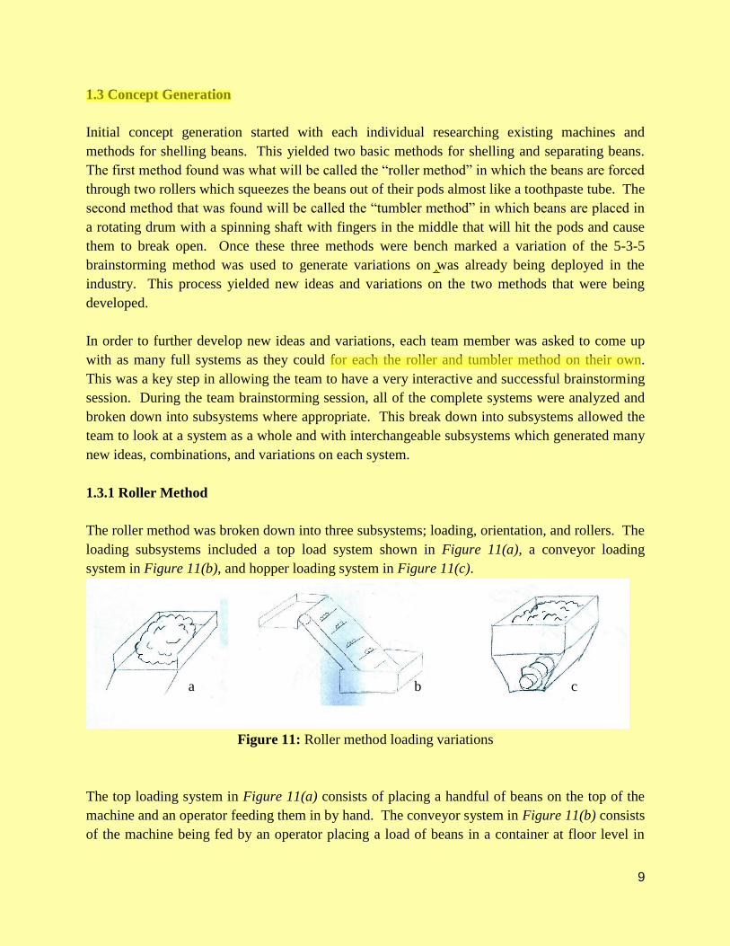
The roller method was broken down into three subsystems; loading, orientation, and rollers. The
loading subsystems included a top load system shown in Figure 11(a), a conveyor loading
system in Figure 11(b), and hopper loading system in Figure 11(c).
Figure 11: Roller method loading variations
The top loading system in Figure 11(a) entails placing a handful of beans on the top of the
machine and feeding them in by hand. The conveyor system in Figure 11(b) consists of the
machine being fed by an operator placing a load of beans in a container at floor level in which a
conveyor would transport the beans to the top at a controlled rate. The hopper system in Figure
11(c) consists of an operator putting a load of beans into a hopper that would then feed the
machine at a rate controlled by the speed of the auger.
The orientation subsystem is a way to orient the bean pods perpendicular to the rollers so they
can pass through the rollers in the correct position. The orientation subsystem for the roller
method included an angled system with fins in Figure 12(a), an angled system with corrugation
in Figure 12(b), a flat system with fins and a conveyor in Figure 12(c), and an angled system
with fins and rollers in Figure 12(d).
Figure 12: Roller method orientation variations
All of the systems in Figure 12(a-d) are all different methods designed to orient the beans in a
perpendicular manner to the rollers.

Page 10 of 22
The rollers subsystem is the part of the machine that actually takes the full pods and separates the
beans from hull. The rollers subsystem included rollers in Figure 13(a), rollers with pre-rollers
in Figure 13(b), rollers with pre-rollers blades in Figure 13(c), and angled rollers in Figure
13(d).
Figure 13: Roller system variations
The roller system in Figure 13(a) consist of two rollers the are spaced closely enough together to
allow only the hull of the bean through the back side and force the beans out of the pod on the
front side. The rollers with pre-rollers in Figure 13(b) implement the same method but use
smaller rollers in front of the main rollers to help with feeding and bean separation. The rollers
with pre-roller blades in Figure 13(c) implement the same method as the pre-rollers but also cut
the pods as they pass through the rollers. The angled rollers in Figure 13(d) are fed vertically
instead of horizontally and have the beans roll down the angled rollers after separation.
[The rest of this page intentionally left blank]
Page 11 of 22
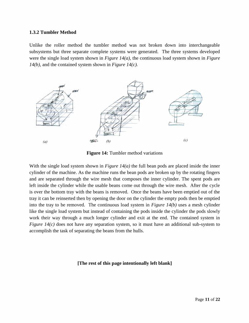
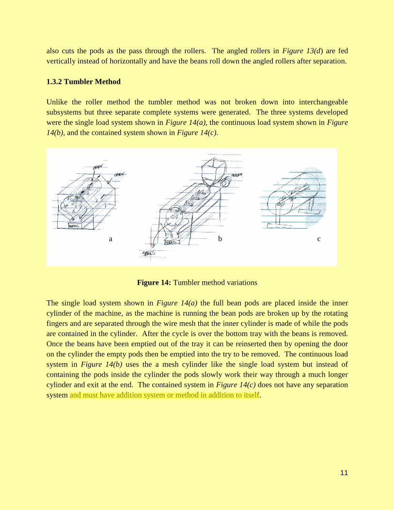
1.3.2 Tumbler Method
Unlike the roller method the tumbler method was not broken down into interchangeable
subsystems but three separate complete systems were generated. The three systems developed
were the single load system shown in Figure 14(a), the continuous load system shown in Figure
14(b), and the contained system shown in Figure 14(c).
Figure 14: Tumbler method variations
With the single load system shown in Figure 14(a) the full bean pods are placed inside the inner
cylinder of the machine. As the machine runs the bean pods are broken up by the rotating fingers
and are separated through the wire mesh that composes the inner cylinder. The spent pods are
left inside the cylinder while the usable beans come out through the wire mesh. After the cycle
is over the bottom tray with the beans is removed. Once the beans have been emptied out of the
tray it can be reinserted then by opening the door on the cylinder the empty pods then be emptied
into the tray to be removed. The continuous load system in Figure 14(b) uses a mesh cylinder
like the single load system but instead of containing the pods inside the cylinder the pods slowly
work their way through a much longer cylinder and exit at the end. The contained system in
Figure 14(c) does not have any separation system, so it must have an additional sub-system to
accomplish the task of separating the beans from the hulls.
[The rest of this page intentionally left blank]

Page 12 of 22
2.0 Concept Screening and Evaluation
2.1 Concept Screening
The team’s concept generation determined several subsystems to accomplish the tasks of
loading, orienting, bean removal, and pod separation. The roller method requires a subsystem
that orients the beans perpendicular to the rollers for proper removal, while the tumbler method
requires no orientation. Also, the tumbler method requires a subsystem that will separate the
shelled beans from the empty pods, while the roller method separates the pod from the bean
when it is removed. Due to the difference in removal method between the tumbler and the
rollers, it was necessary to evaluate the subsystems for loading, orienting, and separating
individually. Each subsystem was then put into a matrix and compared to other variations based
on the following:
● ease of use - how easy it is for the operator to use the machine
● load handling - how well the machine can handle a large load without jamming or failing
● manufacturability - how difficult it will be for the team to manufacture
● versatility - the capability to shell different types of beans
● simplicity - how simple the overall design is
● rate - how fast the machine can remove the beans and separate the empty pods
● certainty of success - the team’s overall certainty that the machine will function properly
Each variation was scored on a 1-5 scale with 1 being the lowest, 3 being neutral, and 5 being the
highest.
2.1.1 Roller Method
The roller method compared the variations in each of the loading, orienting, and roller
subsystems to each other based on the previously stated criterion. Table 2.1 shows the matrix
used to compare the different loading subsystems of the roller method, while Tables 2.2 and 2.3
present the orientation and roller subsystems.
[The rest of this page intentionally left blank]
Page 13 of 22
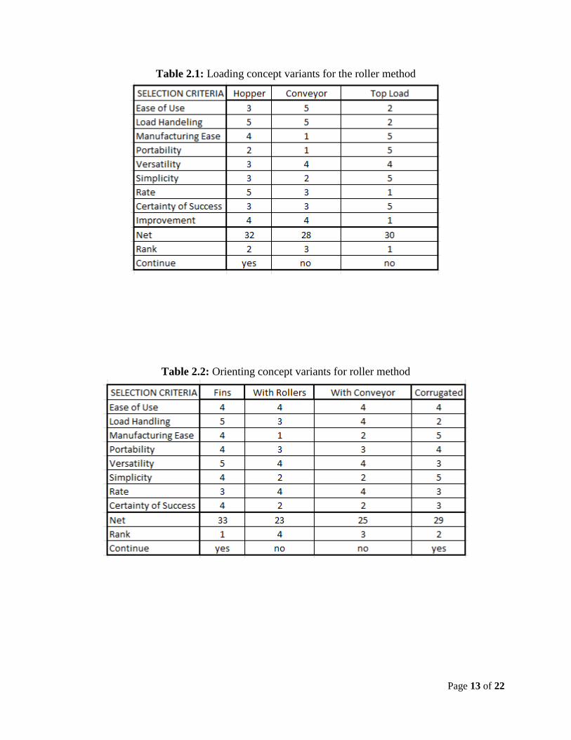
Table 2.1: Loading concept variants for the roller method
Table 2.2: Orienting concept variants for roller method
Page 14 of 22
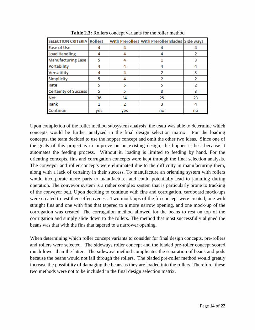
Table 2.3: Rollers concept variants for the roller method
Upon completion of the roller method subsystem analysis, the team was able to determine which
concepts would be further analyzed in the final design selection matrix. For the loading
concepts, the team decided to use the hopper concept and omit the other two ideas. Since one of
the goals of this project is to improve on an existing design, the hopper is best because it
automates the feeding process. Without it, loading is limited to feeding by hand. For the
orienting concepts, fins and corrugation concepts were kept through the final selection analysis.
The conveyor and roller concepts were eliminated due to the difficulty in manufacturing them,
along with a lack of certainty in their success. To manufacture an orienting system with rollers
would incorporate more parts to manufacture, and could potentially lead to jamming during
operation. The conveyor system is a rather complex system that is particularly prone to tracking
of the conveyor belt. Upon deciding to continue with fins and corrugation, cardboard mock-ups
were created to test their effectiveness. Two mock-ups of the fin concept were created, one with
straight fins and one with fins that tapered to a more narrow opening, and one mock-up of the
corrugation was created. The corrugation method allowed for the beans to rest on top of the
corrugation and simply slide down to the rollers. The method that most successfully aligned the
beans was that with the fins that tapered to a narrower opening.
When determining which roller concept variants to consider for final design concepts, pre-rollers
and rollers were selected. The sideways roller concept and the bladed pre-roller concept scored
much lower than the latter. The sideways method complicates the separation of beans and pods
because the beans would not fall through the rollers. The bladed pre-roller method would greatly
increase the possibility of damaging the beans as they are loaded into the rollers. Therefore, these
two methods were not to be included in the final design selection matrix.

Page 15 of 22
2.1.2 Tumbler Method
The tumbler method compared the variations of separating, loading, and the overall performance
of the full systems. Since each tumbler concept entails a specific combination of each loading
method and separating concept, the net score is most important in this case. For example, the
single load can only be used with top loading and two stage separation. Thus the net score of the
three necessary concepts for each method were combined in Table 2.7 in order to determine the
optimal combination for the tumbler method.
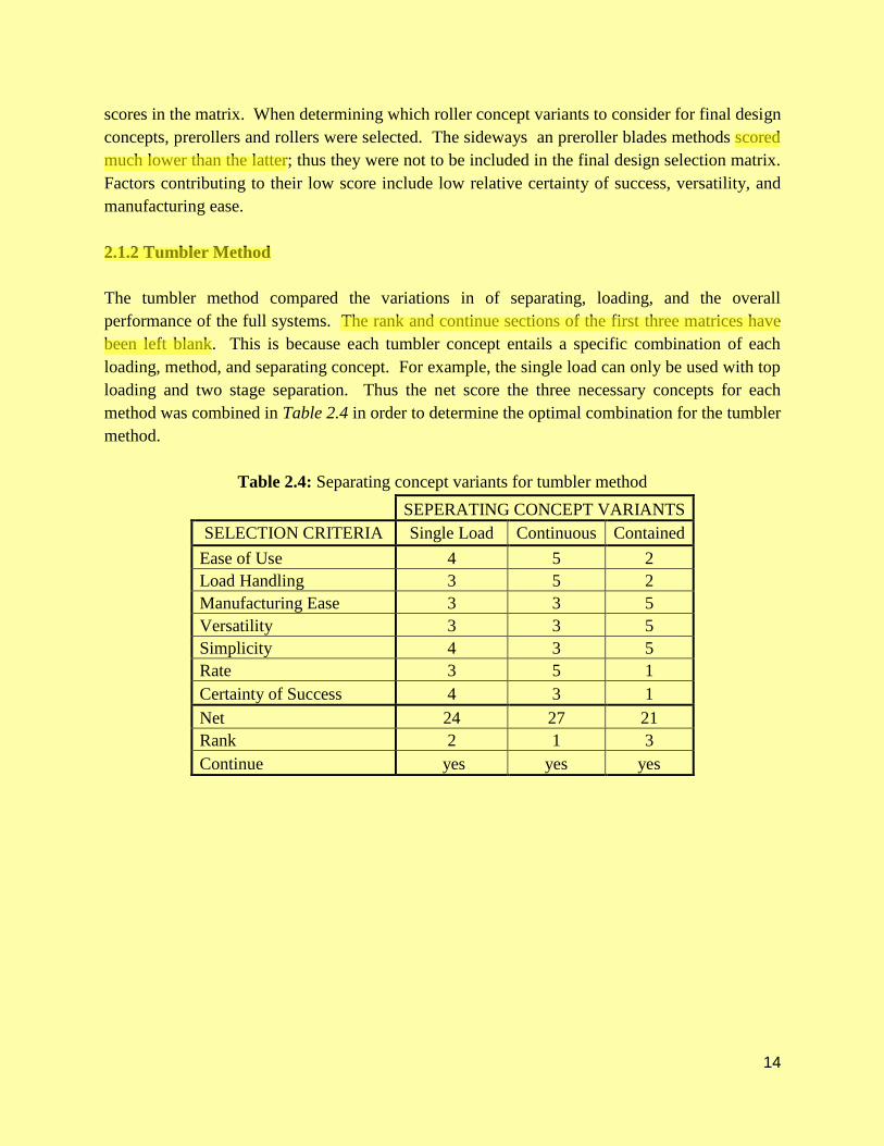
Table 2.4: Separating concept variants for tumbler method
Table 2.5: Method concept variants for tumbler method
[The rest of this page intentionally left blank]

Page 16 of 22
Table 2.6: Loading concept variants for tumbler method
Table 2.7: Analysis of cumulative tumbler method concepts
Upon analysis of cumulative tumbler method concepts, the single load and continuous methods
were chosen for further analysis in the final design selection matrix, since they both received the
highest score (83). The contained method was not included in any further design matrices.
2.2 Data and Calculations for Feasibility and Effectiveness Analysis
Before proceeding with the design, it was necessary to evaluate each of the potential concepts in
terms of feasibility and effectiveness. Feasibility refers to the likelihood of actually completing
the design within our budget and skill set, while effectiveness refers to how well the design will
accomplish the required task. The evaluation for feasibility was concerned with cost of materials
and manufacturability, or the difficulty in actually creating a successful prototype, which
includes the complexity of the design. Since it is important that this machine can be operated by
any able-bodied adult, the weight of a load of beans was considered. Since each individual load
will weigh less than 10 lbs and it will not need to be lifted past the maximum of 80 inches, this
should be manageable for even the weakest operator. The evaluation for effectiveness was
concerned with the rate at which beans were successfully removed from their pods, along with
how well the requirements for weight and size were met. The first step in this analysis was to
benchmark currently available products that employ the bean removal methods used in the
preliminary conceptual designs. This benchmarking provided an understanding of whether or not

Page 17 of 22
a currently available design could meet the customer requirements. Beyond benchmarking,
inspections of potential designs were completed to evaluate the cost of materials and the
difficulty in machining the required parts.
2.2.1 Roller Method
One of the most popular roller-style bean shellers currently available on the market is the Little
Pea Sheller, by Taylor Manufacturing Company, Incorporated. This machine can process beans
at a rate of 3 bushels per hour, meeting the ideal processing rate established in the team’s
specifications. This indicates that this method of bean removal will be effective, and the machine
also meets the specifications for weight and dimensions. The drawback to this machine is its cost
of $475, so the goal for Team Green Bean would be to accomplish the same task at a cheaper
cost [8]. This leads to an evaluation of feasibility, specifically an evaluation of material cost and
manufacturability. The main area of concern is the method of bean removal, meaning the moving
rollers that pull the bean pod through and squeeze the beans out. Keeping this in mind,
manufacturability is not an issue at all. The only thing that needs to be done is to produce two
parallel rollers, both powered, that turn in opposite directions.
2.2.2 Tumbler Method
A currently available machine that employs the tumbler method is the TaMoCo Huller, also by
Taylor Manufacturing Company, Incorporated. The machine can process 7.5 bushels per hour,
far exceeding the specifications established by the team [8]. This indicates that the method will
be effective, but there are far more variables involved with this method than there are with the
roller method. This means that the method will be effective if executed properly, but perhaps not
feasible. Along with the uncertainty of feasibility, there are several moving parts involved with
this method. There is a rotating drum, a rotating shaft, and several beaters attached to the rotating
shaft that swing freely. The necessity of all of these parts increases the cost of materials, and
greatly decreases the ease of manufacturing. These additional difficulties make the tumbler
method the more difficult approach.
[The rest of this page intentionally left blank]
Page 18 of 22
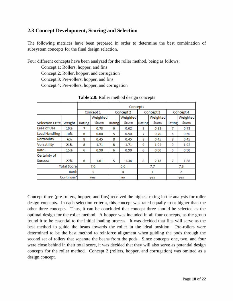
2.3 Concept Development, Scoring and Selection
The following matrices have been prepared in order to determine the best combination of
subsystem concepts for the final design selection.
Four different concepts have been analyzed for the roller method, being as follows:
Concept 1: Rollers, hopper, and fins
Concept 2: Roller, hopper, and corrugation
Concept 3: Pre-rollers, hopper, and fins
Concept 4: Pre-rollers, hopper, and corrugation
Table 2.8: Roller method design concepts
Concept three (pre-rollers, hopper, and fins) received the highest rating in the analysis for roller
design concepts. In each selection criteria, this concept was rated equally to or higher than the
other three concepts. Thus, it can be concluded that concept three should be selected as the
optimal design for the roller method. A hopper was included in all four concepts, as the group
found it to be essential to the initial loading process. It was decided that fins will serve as the
best method to guide the beans towards the roller in the ideal position. Pre-rollers were
determined to be the best method to reinforce alignment when guiding the pods through the
second set of rollers that separate the beans from the pods. Since concepts one, two, and four
were close behind in their total score, it was decided that they will also serve as potential design
concepts for the roller method. Concept 2 (rollers, hopper, and corrugation) was omitted as a
design concept.
Page 19 of 22
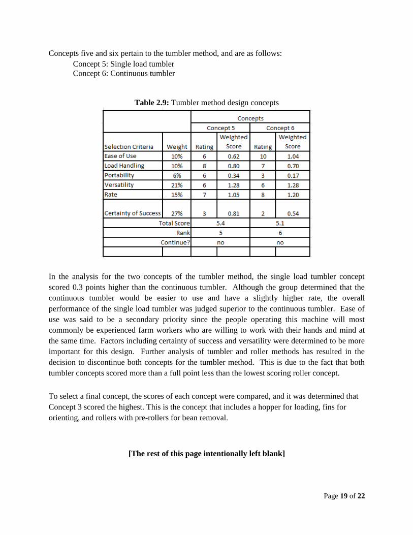
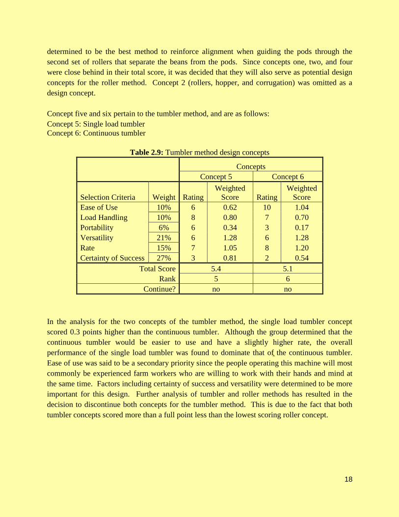
Concepts five and six pertain to the tumbler method, and are as follows:
Concept 5: Single load tumbler
Concept 6: Continuous tumbler
Table 2.9: Tumbler method design concepts
In the analysis for the two concepts of the tumbler method, the single load tumbler concept
scored 0.3 points higher than the continuous tumbler. Although the group determined that the
continuous tumbler would be easier to use and have a slightly higher rate, the overall
performance of the single load tumbler was judged superior to the continuous tumbler. Ease of
use was said to be a secondary priority since the people operating this machine will most
commonly be experienced farm workers who are willing to work with their hands and mind at
the same time. Factors including certainty of success and versatility were determined to be more
important for this design. Further analysis of tumbler and roller methods has resulted in the
decision to discontinue both concepts for the tumbler method. This is due to the fact that both
tumbler concepts scored more than a full point less than the lowest scoring roller concept.
To select a final concept, the scores of each concept were compared, and it was determined that
Concept 3 scored the highest. This is the concept that includes a hopper for loading, fins for
orienting, and rollers with pre-rollers for bean removal.
[The rest of this page intentionally left blank]

Page 20 of 22
3. Final Design Concept
The final concept selection was to use the roller method as our means of shelling and separating
the beans and empty pods. The pre-roller design was selected to help assist in feeding the main
rollers as well as assisting in guiding the shelled beans to into the correct bin. The angled fin
orientation systems without the conveyor or roller assistance was selected as a simple and
effective way to orient the pods perpendicular to the rollers. The hopper was selected to provide
a simple and user friendly loading system. Figure 3.1 shows a solid model of the concept with
approximate dimensions (inches).
Figure 3.1: Final Conceptual Design
The conceptual design thus far has approximate dimensions that are open to change pending
results of testing and prototyping. The specific dimensions along with power transmission will
be selected in the future and presented in the final design report.

Page 21 of 22
Works Cited
[1] Price, George B. “Pea Sheller.” No. 43,864. 16 August, 1864.
[2] Hawkins, James M. “Pea and Bean Sheller.” No. 2,183,769. 28 July, 1938.
[3] Aikele, Andreas Jr. “Pea-Sheller.” No. 937,270. 27 July, 1908.
[4] Welborn, Woodrow W. “Vegetrable Peas and Separating the Hulls Therefrom and the
Like.” No. 4,024,877. 24 May, 1977.
[5] Taylor, George., and Taylor, Brett A. “Legume Sheller and Method of Use Thereof.” No.
12/205,094. 5 September, 2008.
[6] Taylor, George F. “Shelling Machine.” No. 5,052,992. 1 March, 1976.
[7] Young, Ellis R. “Pea and Bean Sheller.” No. 308,589. 25 November, 1884.
[8] Taylor Manufacturing Company, inc. “Green Pea and Bean Shelling Equipment”
11/14/2011. www.peasheller.com.

OHIO University Mechanical Engineering Conceptual Design Report
GOOD EARTH BEAN SHELLER
Team Green Bean
Mark Hritz
Michael Seiser
Sean Mefferd
Dan Knuckles
Andrew Janosik
Chris Allen
11-17-2011
GGK
Text Box
> Good start on CD and pretty good discussion of CD process your team is following. > Design report quality meets most expectations but could be improved by editing & better citations. > The evidence for CD scoring and selection ratings needs to be strengthened, images showing human interaction throughout all modes of operation need to be included to fully define the concept, and some physical mock-ups and calculations need to be completed before the concept can be fully developed and approved. Also, please include the completed CD selection checklist and evidence of project mentor feedback relative to final concept selection in your final draft of the CD report. > Please see comments throughout report and in CD presentation.
2
1.0 Concept Generation
1.1 Problem Statement for Concept Generation
Due to the gap between small gardens and large commercial farms, there is a need for automated
mechanical systems to perform time consuming tasks on medium scale farms. Farms of this size
include those run by independent farmers or non-profit farms that operate on a volunteer basis. In
particular, there is a need for a machine that will accept a variety bean pods as input and produce
shelled beans as output, with little to no work required by the operator.
The first step in concept generation was to identify the methods currently employed to
accomplish this task. The black box model was then used as a basis for each member of the team
to generate various complete system concepts. Upon identifying successful methods to remove
beans from pods, the black box was designated as a complete system that takes bean pods in and
outputs shelled beans. Each member of the team was required to define their complete system
including all subsystems. Circular brainstorming was then employed to identify the strengths,
weaknesses, and possible opportunities for improvement of each concept.
1.2 Patent Search
The patent search performed by the group resulted in a large variety of concepts that have been
previously designed. The patented concepts that were found varied in scale and method. The
patents also varied in age, with some dating back to the mid 1800’s. The patents were sorted by
method of operation and several of the most relate able patents to our concept design are shown
below.
1.2.1 Roller Method Patents
The first group of patents shown uses the “roller method” for de-shelling beans. In general,
patents for this method were the oldest. Also, these patented concepts are for a small scale
operation. Figure 1.1 shows a patented roller method “pea sheller.”
GGK
Cross-Out
GGK
Replacement Text
relevant
GGK
Comment on Text
Excellent job on the content in this section. You should include the actual patent numbers and citations for the images and ideas that are used directly from those patents.

3
Figure 1.1: Roller Method “Pea Sheller”; No. 43,364
The concept shown above is from 1864. It uses a hand crank to drive the main two rollers and a
conveyor feed system. The conveyor is driven by a pulley system. The gap between the two
rollers can be easily adjusted with a screw mechanism at the top of the machine. The beans are
separated from their pods after they move through the rollers. This method of separation is
different from most of the other roller method designs. The most typical method of separation is
getting the peas to stay on the feed side of the rollers while the pods move to the other side.
Another patented concept is shown below in Figures 1.2 and Figure 1.3.
Figure 1.2: Double Roller Mechanism

4
In this design, two sets of rollers are used to de-shell the beans. When the beans go through the
first set of rollers, they are sliced open by the bottom roller. The top roller has ridges on it to
help pull the beans through. This process is shown in Figure 1.2. The next set of rollers are
placed close together so that the pods get pulled through but the beans are left behind as shown
in Figure 1.2.
Figure 1.3: “Pre-slicing” method
Another common design of roller systems is to have some type of gripping features on the
rollers. One patent that incorporates this design is shown in Figure 1.4.
Figure 1.4: Sheller with Studded Rollers
The above patent is for a small scale sheller which has two very small studded rollers.

5
1.2.2 “Tumbler” Method Patents
The next group of patents shown is for “tumbler” style shelling mechanisms. These types of
machines consist of spinning arms inside of a cylinder that break the beans out of their pods.
Tumbler style machines can typically handle a much higher load capacity than that of the roller
method machines. A simple design for a tumbler method machine is shown below in Figures 1.5
and Figure 1.6.
Figure 1.5: Tumbler Front View
Figure 1.6: Tumbler Side View

6
This machine, along with most tumbler machines, uses a screen with holes made to the proper
size for shelled beans to fall through and leaving the pod remnants inside the chamber. After all
the beans are shelled, the pods are removed from the device, and a new batch of beans can be
loaded for the next run. Tumbler method machines can become increasingly complex and
efficient. Figure 1.7 shows a more complicated design.
Figure 1.7: Advanced Tumbler Machine
This machine operates on the same basic principles as the previously shown mechanism but has
several additional features. First, this machine includes a two piece sliding screen that allows for
easy hole size adjustment. Instead of the shelled beans falling straight into a bin after falling
through the screen, the beans fall onto a conveyor. The conveyor moves the beans to an air
blower contraption that further sorts the beans from any small, unwanted debris that may have
fallen through the screen. The debris is lighter than the beans, and blows up into a separate
container. This process is shown in Figure 1.8.
7
Figure 1.8: Blower Mechanism
Another patented design, shown in Figures 1.9 and Figure1.10 includes several different features
of another complex tumbler machine.
Figure 1.9: Alternative Tumbler Design

8
The first unique feature in this design is that the cylindrical drum both turns and rows the beaters.
The patent calls out a rotational speed ratio of the beaters to drum of 5:1. The drum spins in the
opposite direction as the beaters. Another different feature of this design is that the beaters have
free spinning forks at the ends. The patent calls out several different types of interchangeable
tips that can be used at the ends of the beaters for different applications. This design also
includes a method for further sorting beans from hull debris after the screen of the main drum.
The design uses offset shafts on pulleys to make two sets of screens vibrate. The vibration
motion moves the beans over the screens and sorts them accordingly into collection buckets.
1.2.3 “Shearing” Method Patents
The next method of patents is for the “shearing” method. This method of shelling beans is not as
prominent as the roller or tumbler methods. Only one patent was found for a machine of this
type. The design is shown in Figure 1.10.
Figure 1.10: Shearing Mechanism
This device uses a hopper to feed the beans down. Once at the bottom of the hopper, the beans
are grabbed by teeth from a spinning disc. The beans are then dragged across a stationary set of
teeth and are torn open. As the beans are freed from their pods, they fall down out of the
mechanism. The ground-up pods fall into the same area.
9
1.3 Concept Generation
Initial concept generation started with each individual researching existing machines and
methods for shelling beans. This yielded two basic methods for shelling and separating beans.
The first method found was what will be called the “roller method” in which the beans are forced
through two rollers which squeezes the beans out of their pods almost like a toothpaste tube. The
second method that was found will be called the “tumbler method” in which beans are placed in
a rotating drum with a spinning shaft with fingers in the middle that will hit the pods and cause
them to break open. Once these three methods were bench marked a variation of the 5-3-5
brainstorming method was used to generate variations on was already being deployed in the
industry. This process yielded new ideas and variations on the two methods that were being
developed.
In order to further develop new ideas and variations, each team member was asked to come up
with as many full systems as they could for each the roller and tumbler method on their own.
This was a key step in allowing the team to have a very interactive and successful brainstorming
session. During the team brainstorming session, all of the complete systems were analyzed and
broken down into subsystems where appropriate. This break down into subsystems allowed the
team to look at a system as a whole and with interchangeable subsystems which generated many
new ideas, combinations, and variations on each system.
1.3.1 Roller Method
The roller method was broken down into three subsystems; loading, orientation, and rollers. The
loading subsystems included a top load system shown in Figure 11(a), a conveyor loading
system in Figure 11(b), and hopper loading system in Figure 11(c).
Figure 11: Roller method loading variations
The top loading system in Figure 11(a) consists of placing a handful of beans on the top of the
machine and an operator feeding them in by hand. The conveyor system in Figure 11(b) consists
of the machine being fed by an operator placing a load of beans in a container at floor level in
a b c
GGK
Cross-Out
GGK
Inserted Text
what
GGK
Cross-Out
GGK
Comment on Text
edit
GGK
Comment on Text
Well organized section with good level of detail. It would be helpful to show one or more representative system-level sketches from this early brainstorming.

10
which a conveyor would transport the beans at a controlled rate to the top. The hopper system in
Figure 11(c) consists of an operator putting a load of beans into a hopper that would then feed
the machine at a controlled rate by the speed of the auger.
The orientation subsystem is a way to orient the bean pods perpendicular to the rollers so they
can pass through the rollers in the correct position. The orientation subsystem for the roller
method included an angled system with fins in Figure 12(a), an angled system with corrugation
in Figure 12(b), an angled system is fins and rollers in a Figure 12(c), and a flat system with fins
and a conveyor in Figure 12(d).
Figure 12: Roller method orientation variations
All of the systems in Figure 12(a-d) are all different methods designed to orient the beans in a
perpendicular manner to the rollers.
The rollers subsystem is the part of the machine that actually takes the full pods and separates the
beans from hull. The rollers subsystem included rollers in Figure 13 (a), rollers with pre-rollers
in Figure 13(b), rollers with pre-rollers blades in Figure 13 (c), and angled rollers in Figure
13(d).
Figure 13: Roller system variations
The roller system in Figure 13(a) consist of two rollers the are spaced closely enough together to
allow only the hull of the bean through the back side and force the beans out of the pod on the
front side. The rollers with pre-rollers in Figure 13(b) implement the same method but with
smaller rollers in front of the main rollers to help with feeding and bean separation. The rollers
with pre-roller blades in Figure 13(c) also implements the same method as the pre-rollers but
a b c d
a b c d
11
also cuts the pods as the pass through the rollers. The angled rollers in Figure 13(d) are fed
vertically instead of horizontally and have the beans roll down the angled rollers after separation.
1.3.2 Tumbler Method
Unlike the roller method the tumbler method was not broken down into interchangeable
subsystems but three separate complete systems were generated. The three systems developed
were the single load system shown in Figure 14(a), the continuous load system shown in Figure
14(b), and the contained system shown in Figure 14(c).
Figure 14: Tumbler method variations
The single load system shown in Figure 14(a) the full bean pods are placed inside the inner
cylinder of the machine, as the machine is running the bean pods are broken up by the rotating
fingers and are separated through the wire mesh that the inner cylinder is made of while the pods
are contained in the cylinder. After the cycle is over the bottom tray with the beans is removed.
Once the beans have been emptied out of the tray it can be reinserted then by opening the door
on the cylinder the empty pods then be emptied into the try to be removed. The continuous load
system in Figure 14(b) uses the a mesh cylinder like the single load system but instead of
containing the pods inside the cylinder the pods slowly work their way through a much longer
cylinder and exit at the end. The contained system in Figure 14(c) does not have any separation
system and must have addition system or method in addition to itself.
a b c
GGK
Comment on Text
edit

12
2. Concept Screening and Evaluation
2.1 Concept Screening
Through the team’s concept generation each different method was broken down either into
separate full systems or interchangeable subsystems. Each full system or subsystem was then
put into a matrix and compared to other variations based on ease of use, load handling,
manufacturing ease, portability, versatility, simplicity, rate, and certainty of success. Each
criteria pertains to the following: ease of use refers to how easy it is for the operator to use the
machine; load handling refers to how large of a load can be put into the machine with out it
jamming or failing; manufacturing ease refers to how difficult it will be for the team to make;
versatility refers to the capability to shell different types of beans; simplicity refers to how
simple the overall design is; rate refers to how fast the machine can separate the shelled beans
from their pods, and certainty of success refers to the team’s overall certainty if the machine can
be built and work. Each variation was scored on a 1-5 scale with 1 being the lowest, 3 being
neutral, and 5 being the highest.
2.1.1 Roller Method
The roller method compared the variations in each of the loading, orientation, and roller
subsystems to each other based on the previously stated criteria. Table 2.1 shows the matrix
used to compare the different loading subsystems of the roller method, Table 2.2 shows the
matrix used to compare the different orientation methods of the roller method, and Table 2.3
show the matrix used to compare the various rollers.
Table 2.1: Loading concept variants for the roller method
LOADING CONCEPT VARIANTS
SELECTION CRITERIA Hopper Conveyor Top Load
Ease of Use 3 5 2
Load Handling 5 5 2
Manufacturing Ease 4 1 5
Portability 2 1 5
Versatility 3 4 4
Simplicity 3 2 5
Rate 5 3 1
Certainty of Success 3 3 5
Improvement 4 4 1
Net 32 28 30
Rank 2 3 1
Continue yes no yes
GGK
Comment on Text
Good information, and it is acceptable the way it is written, but It seems that a simple table or bullet list would be a better communication tool for these 'definitions.'
GGK
Comment on Text
Please talk about your approach to comparing the core systems (rollers vs tumblers) before jumping right in. It appears that you decided that you could not compare them until each was integrated into a full system, so you used a filtering process to determine accessory components for each to allow the final comparison. If that is true, describe it first. Also, I am not sure why the loading system is unique between roller and tumbler method, but you have treated it separately. Please explain why that is necessary.

13
Table 2.2: Orienting concept variants for roller method
ORIENTING CONCEPT VARIANTS
SELECTION CRITERIA Fins With Rollers With Conveyor Corrugated
Ease of Use 4 4 4 4
Load Handling 5 3 4 2
Manufacturing Ease 4 1 2 5
Portability 4 3 3 4
Versatility 5 4 4 3
Simplicity 4 2 2 5
Rate 3 4 4 3
Certainty of Success 4 2 2 3
Net 33 23 25 29
Rank 1 4 3 2
Continue yes no no yes
Table 2.3: Rollers concept variants for the roller method
ROLLERS CONCEPT VARIANTS
SELECTION CRITERIA Rollers With
Prerollers
With Preroller
Blades Side ways
Ease of Use 4 4 4 4
Load Handling 4 4 4 2
Manufacturing Ease 5 4 1 3
Portability 4 4 4 4
Versatility 4 4 2 3
Simplicity 5 4 2 2
Rate 5 5 5 2
Certainty of Success 5 5 3 3
Net 36 34 25 23
Rank 1 2 3 4
Continue yes yes no no
Upon completion of the roller method subsystem analysis, the team was able to determine which
concepts would be further analyzed in the final design selection matrix. For the loading
concepts, the team decided to use the hopper concept and omit the other two ideas. Originally,
top loading was going to be continued but since one of the goals of this project is to improve on
an existing design, the the hopper would be an improvement whereas the top loading concept
already exists. For the orienting concepts, fins and corrugation concepts were kept through the
final selection analysis, and the conveyer and roller concepts were eliminated due to their low
GGK
Highlight
GGK
Comment on Text
Why? Without some explanation of the numbers used in the tables and what the team and customer thinks the real improvement is, you do not have a convincing argument.
GGK
Comment on Text
What were the differentiators that led to the low scores relative to the corrugated and fins. It seems to me that all you did was select gravity fed versus an active feed system. But I do not know what you are basing this evaluation on. I doubt you can know what will work until you build a mockup and test some beans to see if gravity fed orienting works. This should be an easy mockup and should be done before trying to justify a decision on the orienting subsystem.
14
scores in the matrix. When determining which roller concept variants to consider for final design
concepts, prerollers and rollers were selected. The sideways an preroller blades methods scored
much lower than the latter; thus they were not to be included in the final design selection matrix.
Factors contributing to their low score include low relative certainty of success, versatility, and
manufacturing ease.
2.1.2 Tumbler Method
The tumbler method compared the variations in of separating, loading, and the overall
performance of the full systems. The rank and continue sections of the first three matrices have
been left blank. This is because each tumbler concept entails a specific combination of each
loading, method, and separating concept. For example, the single load can only be used with top
loading and two stage separation. Thus the net score the three necessary concepts for each
method was combined in Table 2.4 in order to determine the optimal combination for the tumbler
method.
Table 2.4: Separating concept variants for tumbler method
SEPERATING CONCEPT VARIANTS
SELECTION CRITERIA Single Load Continuous Contained
Ease of Use 4 5 2
Load Handling 3 5 2
Manufacturing Ease 3 3 5
Versatility 3 3 5
Simplicity 4 3 5
Rate 3 5 1
Certainty of Success 4 3 1
Net 24 27 21
Rank 2 1 3
Continue yes yes yes
GGK
Comment on Text
Again, without some discussion all you are saying is 'trust us.' Explain the logic of the argument which is organized in the table, do not just point to the table and say that is the reason. You would especially want to make the case that you have enough info to judge these alternatives. For example what is the certainty of success rating based on?
GGK
Comment on Text
?
GGK
Comment on Text
Same comments as in above section.

15
Table 2.5: Method concept variants for tumbler method
METHOD CONCEPT VARIANTS
SELECTION
CRITERIA Single Load Continuous Contained
Ease of Use 3 5 2
Load Size 3 5 3
Manufacturing Ease 4 2 5
Portability 4 2 5
Versatility 4 4 4
Simplicity 4 3 5
Rate 3 5 2
Certainty of Success 4 3 4
Net 29 29 30
Rank 2 2 1
Continue yes yes yes
Table 2.6: Loading concept variants for tumbler method
LOADING CONCEPT VARIANTS
SELECTION CRITERIA Hopper Top Load
Ease of Use 2 3
Load Handling 5 2
Manufacturing Ease 4 5
Portability 2 5
Versatility 3 4
Simplicity 3 5
Rate 5 1
Certainty of Success 3 5
Net 27 30
Rank 2 1
Continue yes yes
Table 2.7: Analysis of cumulative tumbler method concepts
Method Separation Loading Total
Single Load 29 24 30 83
Continuous 29 27 27 83
Contained 30 21 30 81
16
Upon analysis of cumulative tumbler method concepts, the single load and continuous methods
were chosen for further analysis in the final design selection matrix, since they both received the
highest score (83). The contained method was not included in any further design matrices.
2.2 Data and Calculations for Feasibility and Effectiveness Analysis
Before proceeding with the design, it was necessary to evaluate each of the potential concepts in
terms of feasibility and effectiveness. Feasibility refers to the likelihood of actually completing
the design within our budget and skill set, while effectiveness refers to how well the design will
accomplish the required task. The evaluation for feasibility was concerned with cost of materials
and manufacturability, or the difficulty in actually creating a successful prototype, which
includes the complexity of the design. The evaluation for effectiveness was concerned with the
rate at which beans were successfully removed from their pods, along with how well the
requirements for weight and size were met. The first step in this analysis was to benchmark
currently available products that employ the bean removal methods used in the preliminary
conceptual designs. This benchmarking provided an understanding of whether or not a currently
available design could meet the customer requirements. Beyond benchmarking, inspections of
potential designs were completed to evaluate the cost of materials and the difficulty in machining
the required parts.
2.2.1 Roller Method
Before proceeding with the design, it was necessary to evaluate each of the potential concepts in
terms of feasibility and effectiveness. Feasibility refers to the likelihood of actually completing
the design within our budget and skill set, while effectiveness refers to how well the design will
accomplish the required task. The evaluation for feasibility was concerned with cost of materials
and manufacturability, or the difficulty in actually creating a successful prototype, which
includes the complexity of the design. The evaluation for effectiveness was concerned with the
rate at which beans were successfully removed from their pods, along with how well the
requirements for weight and size were met. The first step in this analysis was to benchmark
currently available products that employ the bean removal methods used in the preliminary
conceptual designs. This benchmarking provided an understanding of whether or not a currently
available design could meet the customer requirements. Beyond benchmarking, inspections of
potential designs were completed to evaluate the cost of materials and the difficulty in machining
the required parts.
2.2.2 Tumbler Method
Before proceeding with the design, it was necessary to evaluate each of the potential concepts in
terms of feasibility and effectiveness. Feasibility refers to the likelihood of actually completing
the design within our budget and skill set, while effectiveness refers to how well the design will
accomplish the required task. The evaluation for feasibility was concerned with cost of materials
and manufacturability, or the difficulty in actually creating a successful prototype, which
includes the complexity of the design. The evaluation for effectiveness was concerned with the
rate at which beans were successfully removed from their pods, along with how well the
GGK
Comment on Text
These scores are so close, and the uncertainty in your ratings so large, that you cannot use the small score difference to select one over the other. It basically says they are the same, so you would need to use another method to differentiate.
GGK
Comment on Text
Good introduction to this section. You will need to include the torque, speed and power requirements for the main roller and tumbler systems (likely from benchmarking) and a comparison of those requirements to human power, and/or the ballpark cost of a motor to provide those requirements.
GGK
Comment on Text
Just a repeat of last section
GGK
Comment on Text

17
requirements for weight and size were met. The first step in this analysis was to benchmark
currently available products that employ the bean removal methods used in the preliminary
conceptual designs. This benchmarking provided an understanding of whether or not a currently
available design could meet the customer requirements. Beyond benchmarking, inspections of
potential designs were completed to evaluate the cost of materials and the difficulty in machining
the required parts.
2.3 Concept Development, Scoring and Selection
The following matrices have been prepared in order to determine the best combination of
subsystem concepts for the final design selection. Four different concepts have been analyzed
for the roller method, being as follows:
Concept 1: Rollers, hopper, and fins
Concept 2: Roller, hopper, and corrugation
Concept 3: Prerollers, hopper, and fins
Concept 4: Prerollers, hopper, and corrugation
Table 2.8: Roller method design concepts
Concepts
Concept 1 Concept 2 Concept 3 Concept 4
Selection
Criteria Weight Rating
Weighted
Score Rating
Weighted
Score Rating
Weighted
Score Rating
Weighted
Score
Ease of Use 10% 7 0.73 6 0.62 8 0.83 7 0.73
Load Handling 10% 6 0.60 5 0.50 7 0.70 6 0.60
Portability 6% 8 0.45 8 0.45 8 0.45 8 0.45
Versatility 21% 8 1.71 8 1.71 9 1.92 9 1.92
Rate 15% 6 0.90 6 0.90 6 0.90 6 0.90
Certainty of
Success 27% 6 1.61 5 1.34 8 2.15 7 1.88
Total Score 7.0 6.6 7.7 7.3
Rank 3 4 1 2
Continue? yes no yes yes
Concept three (prerollers, hopper, and fins) received the highest rating in the analysis for roller
design concepts. In each selection criteria, this concept was rated equally to or higher than the
other three concepts. Thus, it can be concluded that concept three should be selected as the
optimal design for the roller method. A hopper was included in all four concepts, as the group
found it to be essential to the initial loading process. It was decided that fins will serve as the
best method to guide the beans towards the roller in the ideal position. Prerollers were
GGK
Comment on Text
Same
GGK
Comment on Text
I am not convinced that you have the information needed to make final selection of a concept. If you think you do, be very clear about what you are basing your ratings on and why you think that is sufficient evidence. I really think you need some subsystem mockups before you can finalize your concept.
GGK
Comment on Text
I am confused about how this adds additional information compared to the subsystem analysis. What is different for the subsystems when evaluated as a system?
18
determined to be the best method to reinforce alignment when guiding the pods through the
second set of rollers that separate the beans from the pods. Since concepts one, two, and four
were close behind in their total score, it was decided that they will also serve as potential design
concepts for the roller method. Concept 2 (rollers, hopper, and corrugation) was omitted as a
design concept.
Concept five and six pertain to the tumbler method, and are as follows:
Concept 5: Single load tumbler
Concept 6: Continuous tumbler
Table 2.9: Tumbler method design concepts
Concepts
Concept 5 Concept 6
Selection Criteria Weight Rating
Weighted
Score Rating
Weighted
Score
Ease of Use 10% 6 0.62 10 1.04
Load Handling 10% 8 0.80 7 0.70
Portability 6% 6 0.34 3 0.17
Versatility 21% 6 1.28 6 1.28
Rate 15% 7 1.05 8 1.20
Certainty of Success 27% 3 0.81 2 0.54
Total Score 5.4 5.1
Rank 5 6
Continue? no no
In the analysis for the two concepts of the tumbler method, the single load tumbler concept
scored 0.3 points higher than the continuous tumbler. Although the group determined that the
continuous tumbler would be easier to use and have a slightly higher rate, the overall
performance of the single load tumbler was found to dominate that of the continuous tumbler.
Ease of use was said to be a secondary priority since the people operating this machine will most
commonly be experienced farm workers who are willing to work with their hands and mind at
the same time. Factors including certainty of success and versatility were determined to be more
important for this design. Further analysis of tumbler and roller methods has resulted in the
decision to discontinue both concepts for the tumbler method. This is due to the fact that both
tumbler concepts scored more than a full point less than the lowest scoring roller concept.
GGK
Cross-Out
GGK
Replacement Text
judged superior to

19
3. Final Design Concept
The final concept selection was to use the roller method as our means of shelling and separating
the beans and empty pods. The pre-roller design was selected to help assist in feeding the main
rollers as well as assisting in guiding the shelled beans to into the correct bin. The angled fined
orientation systems without the conveyor or roller assistance was selected as a simple and
effective way to orient the pods perpendicular to the rollers. The hopper and auger combination
was selected to provide a simple and user friendly loading and feed rate system. Figure 3.1
shows a solid model of the concept with approximate dimensions (inches).
Figure 3.1: Final Conceptual Design
The conceptual design thus far has approximate dimensions that are open to change pending
results of testing and prototyping. The specific dimensions along with power source and power
transmission will be selected in the future and give in the final design report.
GGK
Sticky Note
This looks like a clogging problem waiting to happen. You could use an adverse consequences matrix to better include clogging and other 'failure modes' in your concept decisions. Also, as designed less than 50% of the rollers are used - you could significantly shorten the roller width to reduce cost and increase durability if you go with this type of method for 'aligning' the beans.
GGK
Sticky Note
I am not sure what value this adds if you already have the height needed for a gravity feed system.
GGK
Sticky Note
I did not see any discussion of the transportation (portability) subsystem. This needs some conceptual design work.