Notice of Proposed Rulemaking: Pipeline Damage Prevention Programs Docket ID PHMSA-2009-0192
Ohio Gas AssociationPHMSA Pipeline Safety Event
September 15, 2017Kyle Grupenhof, PE
1
Focus: Hydrostatic Testing of Steel Pipelines & Facilities Pros and Cons Code Requirements Pressure Test Design
◦ Establishment of Minimum & Maximum Test Pressures Pressure Test Operations
◦ Filling & Stabilization◦ Testing & Documentation◦ Dewatering & Cleaning
Record Keeping Environmental Permitting Safety Concerns
2
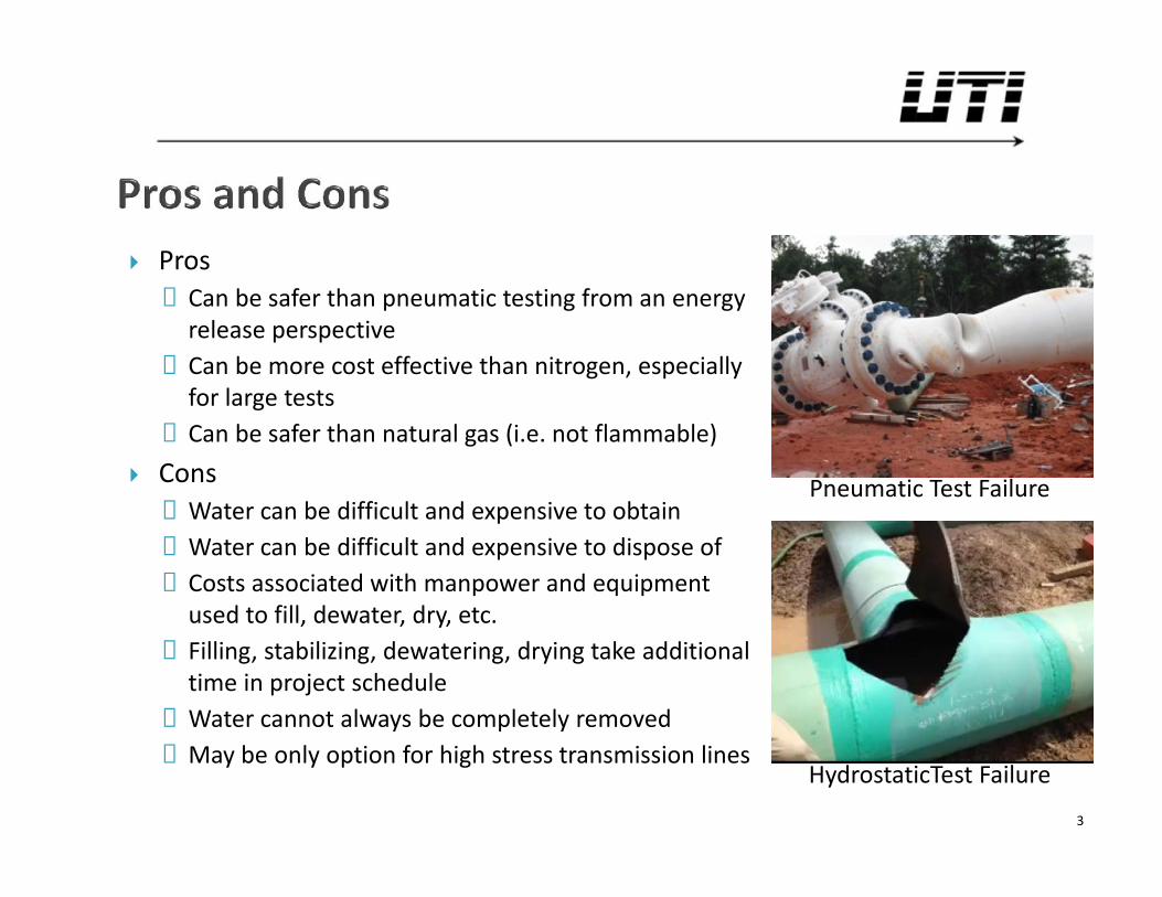
Pros◦ Can be safer than pneumatic testing from an energy
release perspective◦ Can be more cost effective than nitrogen, especially
for large tests◦ Can be safer than natural gas (i.e. not flammable)
Cons◦ Water can be difficult and expensive to obtain◦ Water can be difficult and expensive to dispose of◦ Costs associated with manpower and equipment
used to fill, dewater, dry, etc.◦ Filling, stabilizing, dewatering, drying take additional
time in project schedule◦ Water cannot always be completely removed◦ May be only option for high stress transmission lines
3
Pneumatic Test Failure
HydrostaticTest Failure
§192.503 – General Requirementsa) No person may operate a new segment of pipeline, or return to
service a segment of pipeline that has been relocated or replaced,until:
1) It has been tested in accordance with this subpart [Subpart J] and§192.619 to substantiate the maximum allowable operating pressure; and
2) Each potentially hazardous leak has been located and eliminated.b) The test medium must be liquid, air, natural gas, or inert gas that is:
1) Compatible with the material of which the pipeline is constructed;2) Relatively free of sedimentary materials; and3) Except for natural gas, nonflammable
4
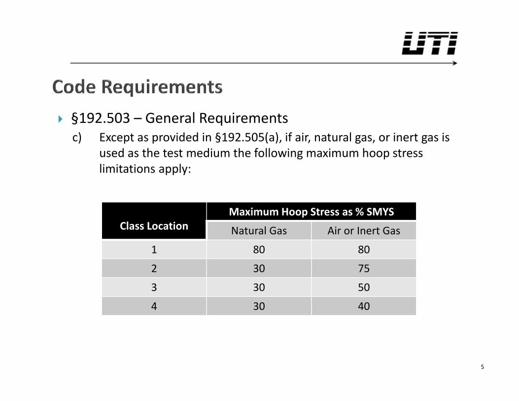
§192.503 – General Requirementsc) Except as provided in §192.505(a), if air, natural gas, or inert gas is
used as the test medium the following maximum hoop stresslimitations apply:
5
Class LocationMaximum Hoop Stress as % SMYS
Natural Gas Air or Inert Gas
1 80 80
2 30 75
3 30 50
4 30 40
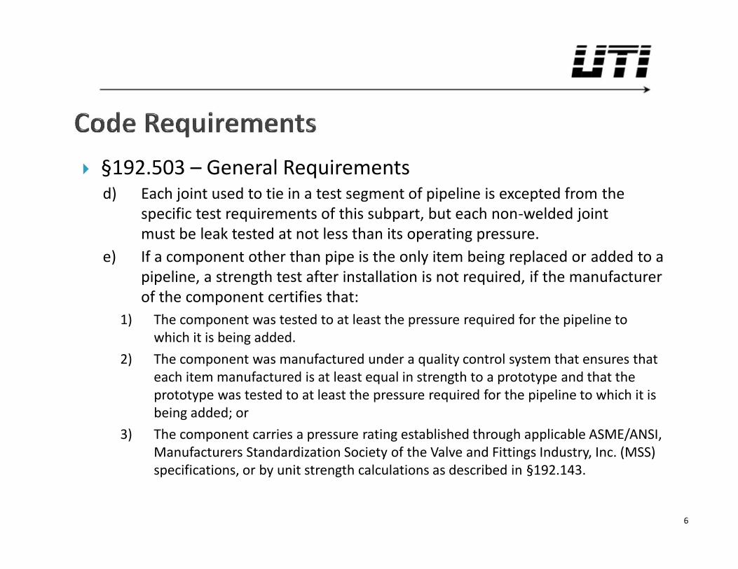
§192.503 – General Requirementsd) Each joint used to tie in a test segment of pipeline is excepted from the
specific test requirements of this subpart, but each non-welded jointmust be leak tested at not less than its operating pressure.
e) If a component other than pipe is the only item being replaced or added to apipeline, a strength test after installation is not required, if the manufacturerof the component certifies that:
1) The component was tested to at least the pressure required for the pipeline towhich it is being added.
2) The component was manufactured under a quality control system that ensures thateach item manufactured is at least equal in strength to a prototype and that theprototype was tested to at least the pressure required for the pipeline to which it isbeing added; or
3) The component carries a pressure rating established through applicable ASME/ANSI,Manufacturers Standardization Society of the Valve and Fittings Industry, Inc. (MSS)specifications, or by unit strength calculations as described in §192.143.
6
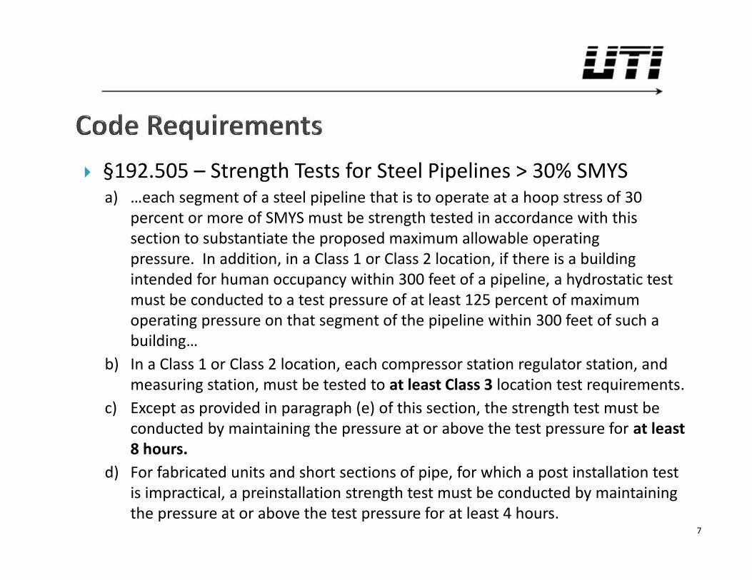
§192.505 – Strength Tests for Steel Pipelines > 30% SMYSa) …each segment of a steel pipeline that is to operate at a hoop stress of 30
percent or more of SMYS must be strength tested in accordance with thissection to substantiate the proposed maximum allowable operatingpressure. In addition, in a Class 1 or Class 2 location, if there is a buildingintended for human occupancy within 300 feet of a pipeline, a hydrostatic testmust be conducted to a test pressure of at least 125 percent of maximumoperating pressure on that segment of the pipeline within 300 feet of such abuilding…
b) In a Class 1 or Class 2 location, each compressor station regulator station, andmeasuring station, must be tested to at least Class 3 location test requirements.
c) Except as provided in paragraph (e) of this section, the strength test must beconducted by maintaining the pressure at or above the test pressure for at least8 hours.
d) For fabricated units and short sections of pipe, for which a post installation testis impractical, a preinstallation strength test must be conducted by maintainingthe pressure at or above the test pressure for at least 4 hours.
7
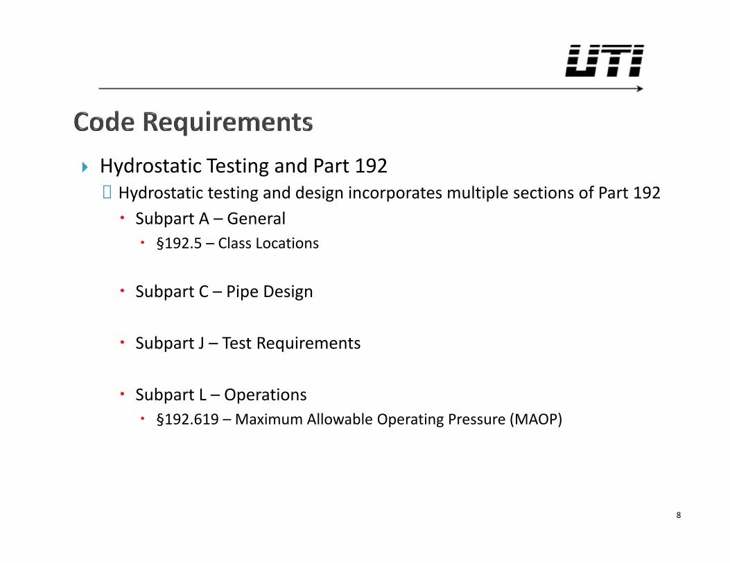
Hydrostatic Testing and Part 192◦ Hydrostatic testing and design incorporates multiple sections of Part 192 Subpart A – General §192.5 – Class Locations
Subpart C – Pipe Design
Subpart J – Test Requirements
Subpart L – Operations §192.619 – Maximum Allowable Operating Pressure (MAOP)
8
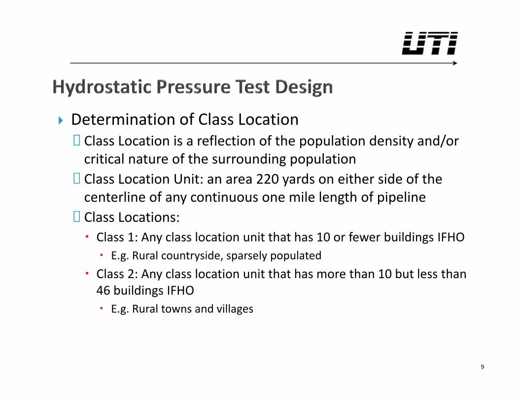
Determination of Class Location◦ Class Location is a reflection of the population density and/or
critical nature of the surrounding population◦ Class Location Unit: an area 220 yards on either side of the
centerline of any continuous one mile length of pipeline◦ Class Locations: Class 1: Any class location unit that has 10 or fewer buildings IFHO E.g. Rural countryside, sparsely populated
Class 2: Any class location unit that has more than 10 but less than46 buildings IFHO E.g. Rural towns and villages
9
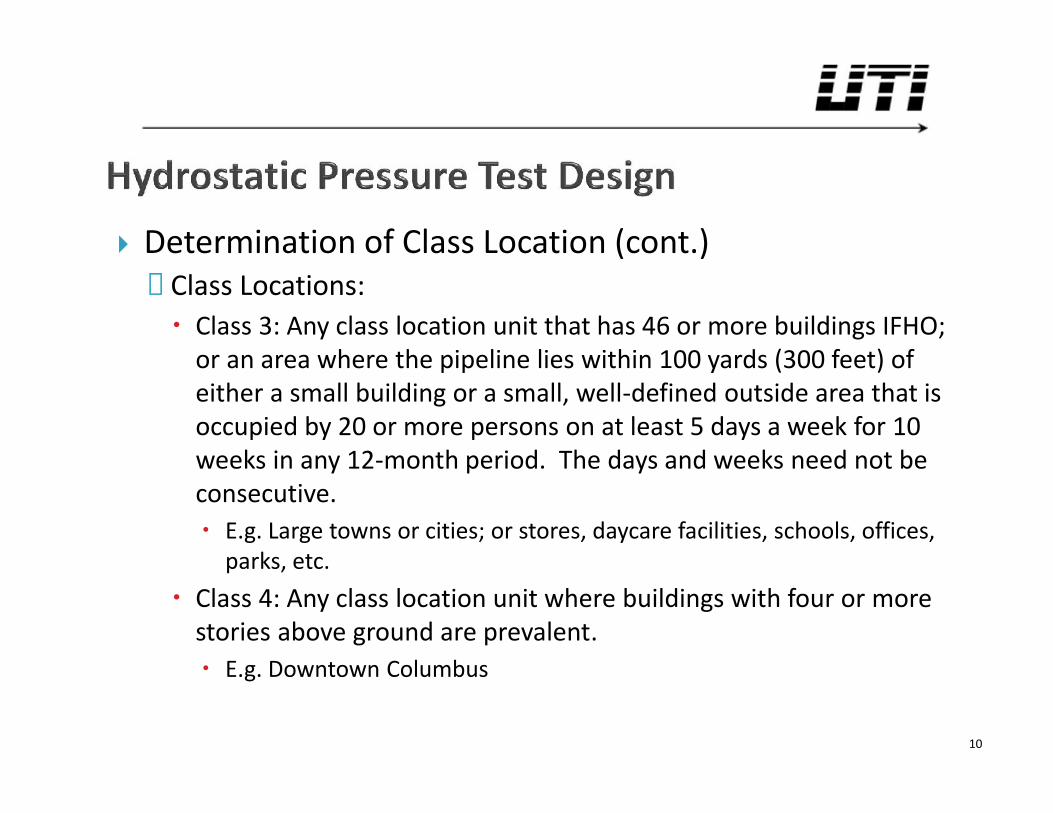
Determination of Class Location (cont.)◦ Class Locations: Class 3: Any class location unit that has 46 or more buildings IFHO;
or an area where the pipeline lies within 100 yards (300 feet) ofeither a small building or a small, well-defined outside area that isoccupied by 20 or more persons on at least 5 days a week for 10weeks in any 12-month period. The days and weeks need not beconsecutive. E.g. Large towns or cities; or stores, daycare facilities, schools, offices,
parks, etc. Class 4: Any class location unit where buildings with four or more
stories above ground are prevalent. E.g. Downtown Columbus
10
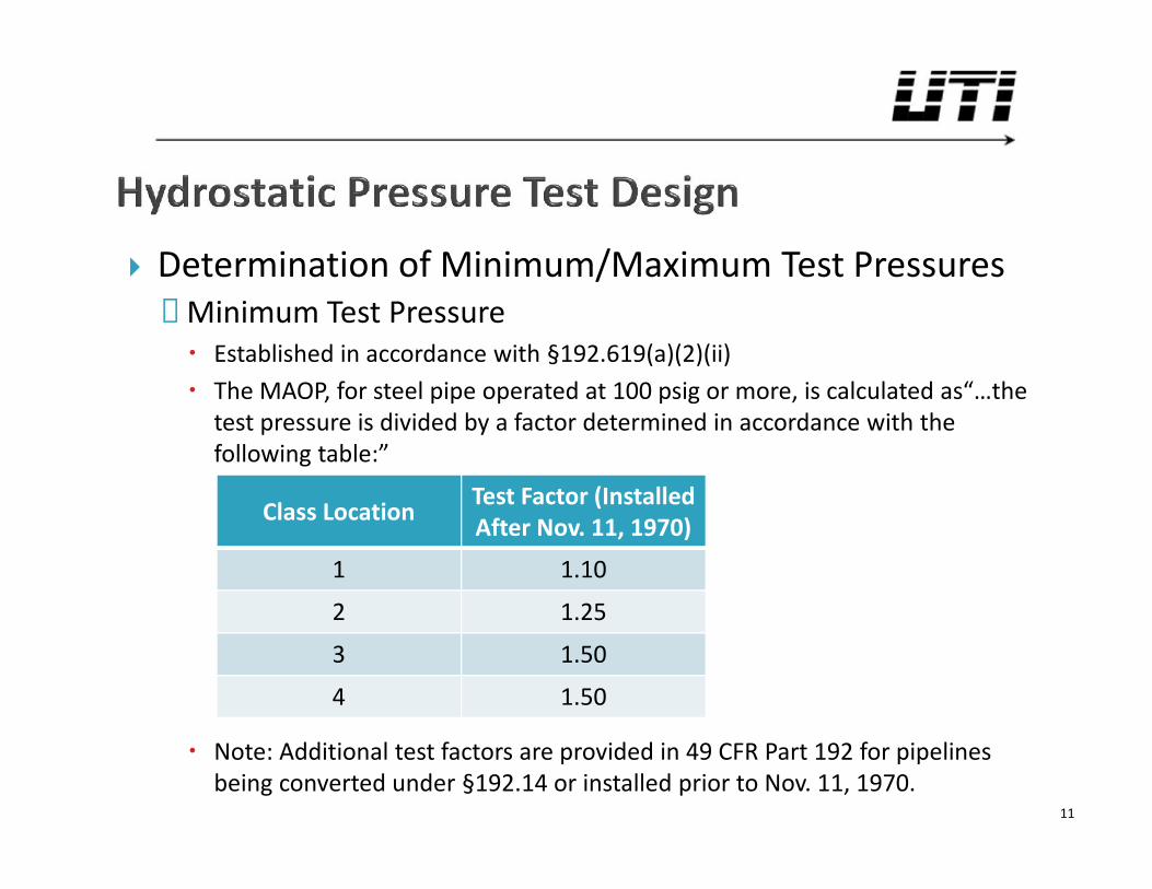
Determination of Minimum/Maximum Test Pressures◦ Minimum Test Pressure Established in accordance with §192.619(a)(2)(ii) The MAOP, for steel pipe operated at 100 psig or more, is calculated as“…the
test pressure is divided by a factor determined in accordance with thefollowing table:”
Note: Additional test factors are provided in 49 CFR Part 192 for pipelinesbeing converted under §192.14 or installed prior to Nov. 11, 1970.
11
Class Location Test Factor (InstalledAfter Nov. 11, 1970)
1 1.10
2 1.25
3 1.50
4 1.50
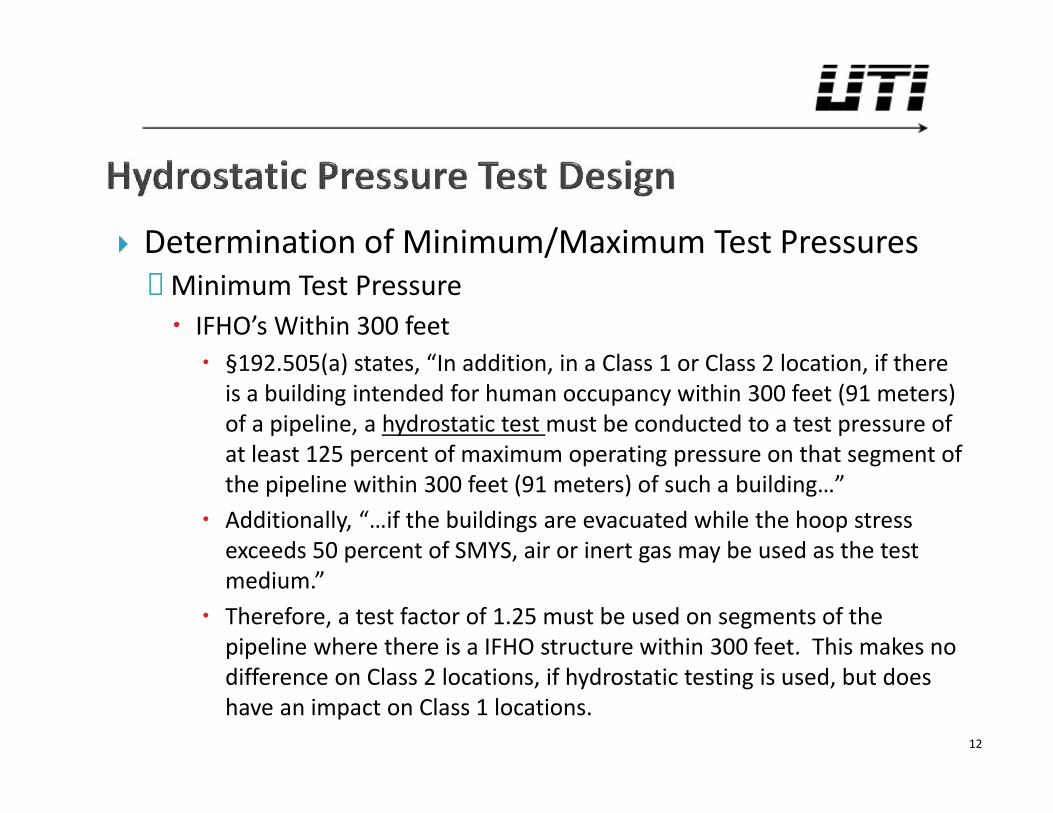
Determination of Minimum/Maximum Test Pressures◦ Minimum Test Pressure IFHO’s Within 300 feet §192.505(a) states, “In addition, in a Class 1 or Class 2 location, if there
is a building intended for human occupancy within 300 feet (91 meters)of a pipeline, a hydrostatic test must be conducted to a test pressure ofat least 125 percent of maximum operating pressure on that segment ofthe pipeline within 300 feet (91 meters) of such a building…” Additionally, “…if the buildings are evacuated while the hoop stress
exceeds 50 percent of SMYS, air or inert gas may be used as the testmedium.” Therefore, a test factor of 1.25 must be used on segments of the
pipeline where there is a IFHO structure within 300 feet. This makes nodifference on Class 2 locations, if hydrostatic testing is used, but doeshave an impact on Class 1 locations.
12
Determination of Minimum/Maximum Test Pressures◦ Minimum Test Pressure Example: A pipeline has a design MAOP of 1,480 psig and is
located entirely within a Class 1 Location (Test Factor = 1.10 per§192.619(a)(2)(ii)). What is the minimum test pressure required,throughout the pipeline, to satisfy an MAOP of 1,480 psig?
1,480 × 1.10 = 1,628 What if it was located in a Class 2 Location (Test Factor = 1.25 per
§192.619(a)(2)(ii))?
1,480 × 1.25 = 1,85013
Determination of Minimum/Maximum Test Pressures◦ Maximum Test Pressure Limited by safe operating pressure of components to be tested Specified Minimum Yield Strength (SMYS) of Pipe Example: 20” 0.375” WT Grade X52 API-5L PSL-2 Pipe SMYS = 1,950 psig SMYS limitations vary by operator – UTI has seen 95% to 110% SMYS Maximum Test Pressure of Component Ratings ASME B16.5 (Flanges & Flanged Fittings), §2.6
“Flanged joints and flanged fittings may be subjected to system hydrostatic tests at apressure of 1.5 times the 38°C (100°F) rating rounded off to the next higher 1 bar (25psi) increment. Testing at any higher pressure is the responsibility of the user, takinginto account the requirements of the applicable code or regulation.”
ANSI 600 Flange Pressure Rating = 1480 psig Max. Test Pressure = 1.5 x 1,480 = 2,220 => 2,225 psig (next higher 25 psig increment)
UTI has seen instances where an operator obtains an approval letter from themanufacturer to allow a test pressure higher than that stated in ASME B16.5
14
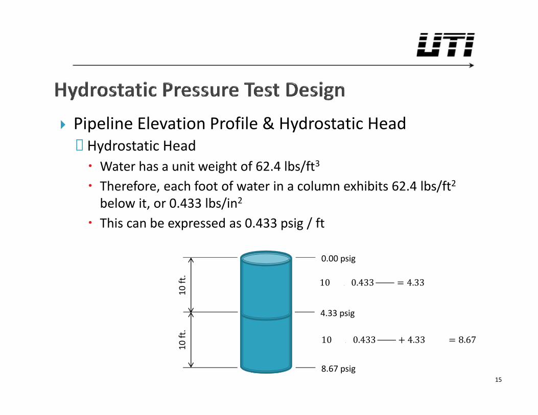
Pipeline Elevation Profile & Hydrostatic Head◦ Hydrostatic Head Water has a unit weight of 62.4 lbs/ft3
Therefore, each foot of water in a column exhibits 62.4 lbs/ft2
below it, or 0.433 lbs/in2
This can be expressed as 0.433 psig / ft
15
0.00 psig
10 ft
.
4.33 psig
8.67 psig
10 ft
.
10 0.433 = 4.3310 0.433 + 4.33 = 8.67
Pipeline Elevation Profile & Hydrostatic Head◦ Hydrostatic Head Example: If a pressure gauge on a pipeline filled with water reads
1,000 psig, what will the pressure be at a location, along thepipeline, 100 feet below?
1,000 + 100 × 0.433 / = 1,043.3 Likewise, what will the pressure be at a location 100 feet above?
1,000 − 100 × 0.433 / = 956.7 Note: Hydrostatic Head is independent of slope of pipe, etc. It
only matters how many vertical feet of water is below.16
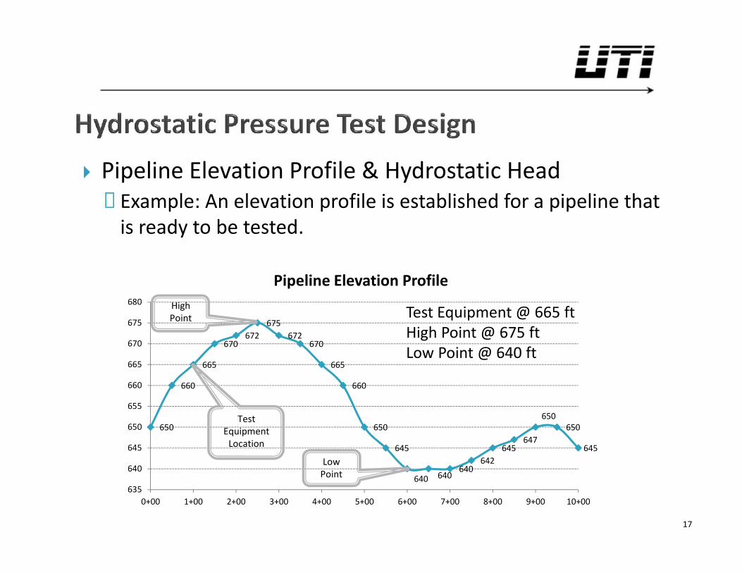
Pipeline Elevation Profile & Hydrostatic Head◦ Example: An elevation profile is established for a pipeline that
is ready to be tested.
17
650
660
665
670672
675672
670
665
660
650
645
640 640640
642645
647
650650
645
635
640
645
650
655
660
665
670
675
680
0+00 1+00 2+00 3+00 4+00 5+00 6+00 7+00 8+00 9+00 10+00
Pipeline Elevation Profile
TestEquipment
Location
HighPoint
LowPoint
Test Equipment @ 665 ftHigh Point @ 675 ftLow Point @ 640 ft
Pipeline Elevation Profile & Hydrostatic Head◦ Example (cont.):
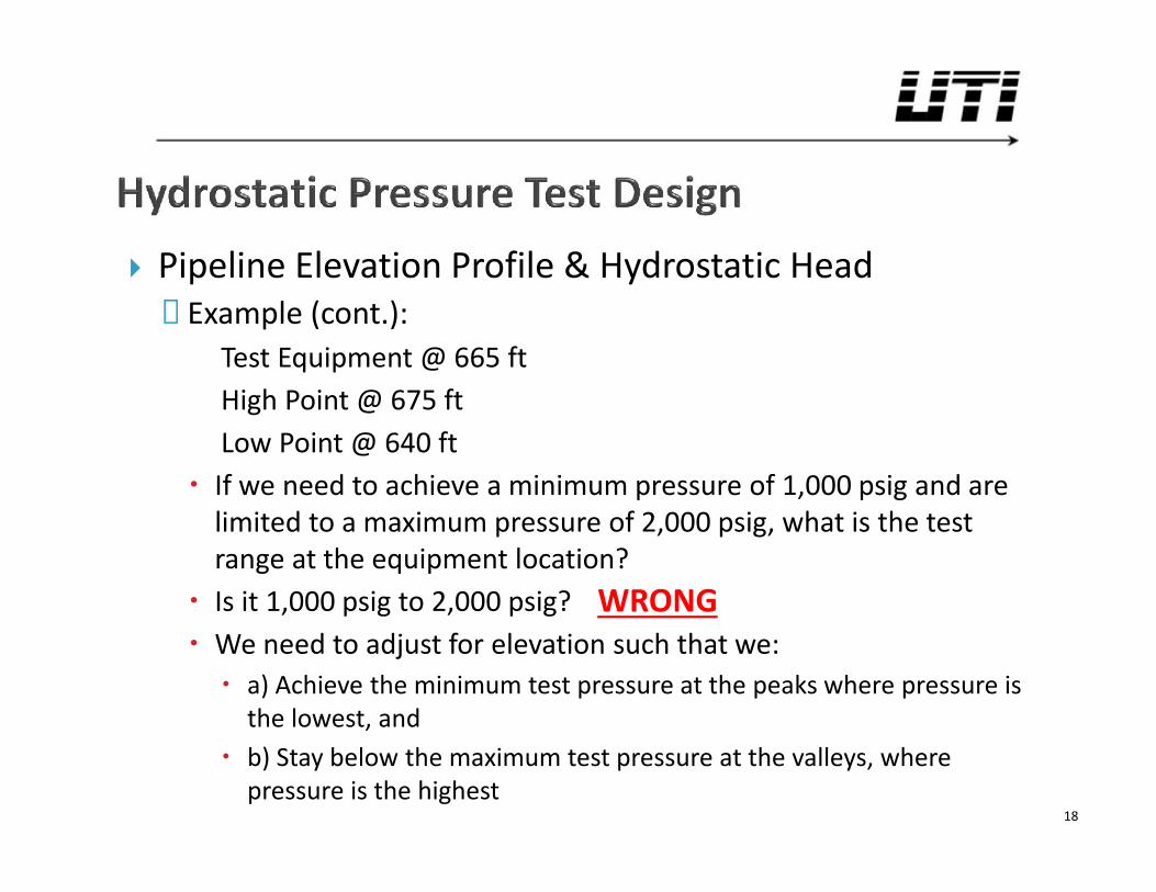
Test Equipment @ 665 ftHigh Point @ 675 ftLow Point @ 640 ft
If we need to achieve a minimum pressure of 1,000 psig and arelimited to a maximum pressure of 2,000 psig, what is the testrange at the equipment location? Is it 1,000 psig to 2,000 psig? We need to adjust for elevation such that we: a) Achieve the minimum test pressure at the peaks where pressure is
the lowest, and b) Stay below the maximum test pressure at the valleys, where
pressure is the highest18
WRONG
Pipeline Elevation Profile & Hydrostatic Head◦ Example (cont.):
19
650
660
665
670672
675672
670
665
660
650
645
640 640640
642645
647
650650
645
635
640
645
650
655
660
665
670
675
680
0+00 1+00 2+00 3+00 4+00 5+00 6+00 7+00 8+00 9+00 10+00
Pipeline Elevation Profile
TestEquipment
Location
HighPoint
LowPoint
Elev.(ft)
Min. Pressure(psig)
Max. Pressure(psig)
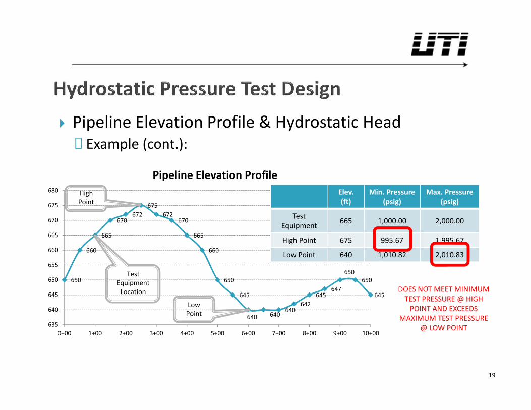
TestEquipment 665 1,000.00 2,000.00
High Point 675 995.67 1,995.67
Low Point 640 1,010.82 2,010.83
DOES NOT MEET MINIMUMTEST PRESSURE @ HIGH
POINT AND EXCEEDSMAXIMUM TEST PRESSURE
@ LOW POINT
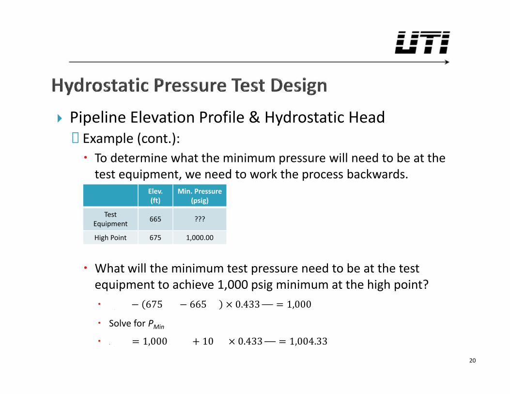
Pipeline Elevation Profile & Hydrostatic Head◦ Example (cont.): To determine what the minimum pressure will need to be at the
test equipment, we need to work the process backwards.
What will the minimum test pressure need to be at the testequipment to achieve 1,000 psig minimum at the high point? − 675 − 665 × 0.433 = 1,000 Solve for PMin = 1,000 + 10 × 0.433 = 1,004.33
20
Elev.(ft)
Min. Pressure(psig)
TestEquipment 665 ???
High Point 675 1,000.00
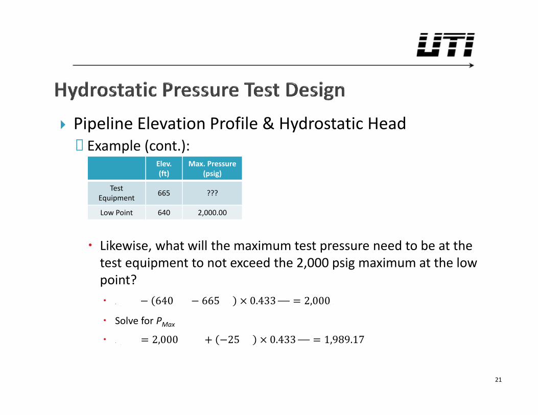
Pipeline Elevation Profile & Hydrostatic Head◦ Example (cont.):
Likewise, what will the maximum test pressure need to be at thetest equipment to not exceed the 2,000 psig maximum at the lowpoint? − 640 − 665 × 0.433 = 2,000 Solve for PMax = 2,000 + −25 × 0.433 = 1,989.17
21
Elev.(ft)
Max. Pressure(psig)
TestEquipment 665 ???
Low Point 640 2,000.00
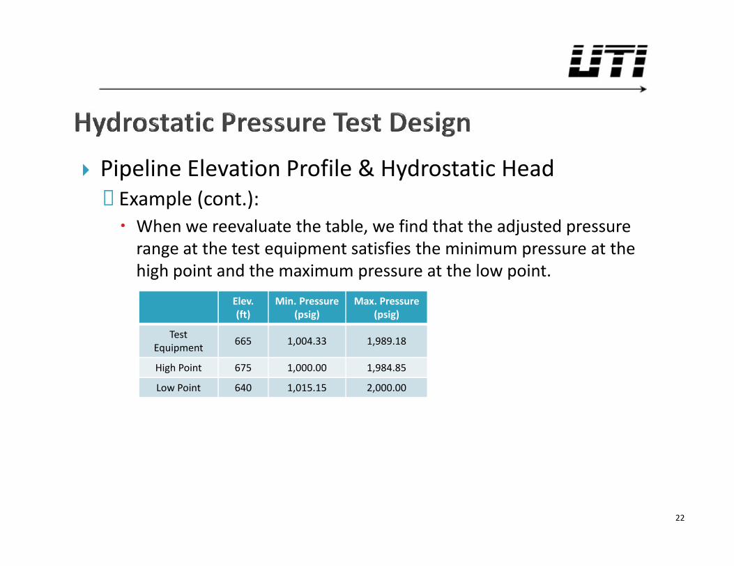
Pipeline Elevation Profile & Hydrostatic Head◦ Example (cont.): When we reevaluate the table, we find that the adjusted pressure
range at the test equipment satisfies the minimum pressure at thehigh point and the maximum pressure at the low point.
22
Elev.(ft)
Min. Pressure(psig)
Max. Pressure(psig)
TestEquipment 665 1,004.33 1,989.18
High Point 675 1,000.00 1,984.85
Low Point 640 1,015.15 2,000.00
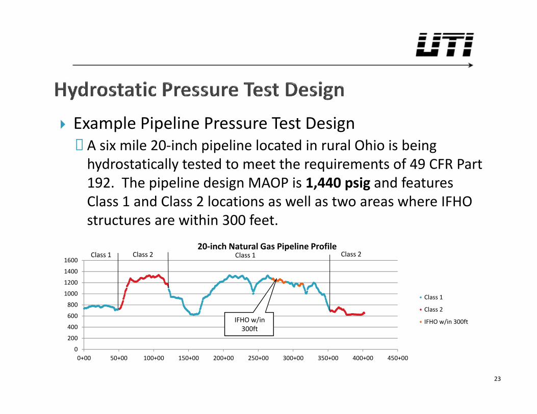
Example Pipeline Pressure Test Design◦ A six mile 20-inch pipeline located in rural Ohio is being
hydrostatically tested to meet the requirements of 49 CFR Part192. The pipeline design MAOP is 1,440 psig and featuresClass 1 and Class 2 locations as well as two areas where IFHOstructures are within 300 feet.
23
0
200
400
600
800
1000
1200
1400
1600
0+00 50+00 100+00 150+00 200+00 250+00 300+00 350+00 400+00 450+00
20-inch Natural Gas Pipeline Profile
Class 1
Class 2
IFHO w/in 300ft
Class 2 Class 2Class 1Class 1
IFHO w/in300ft
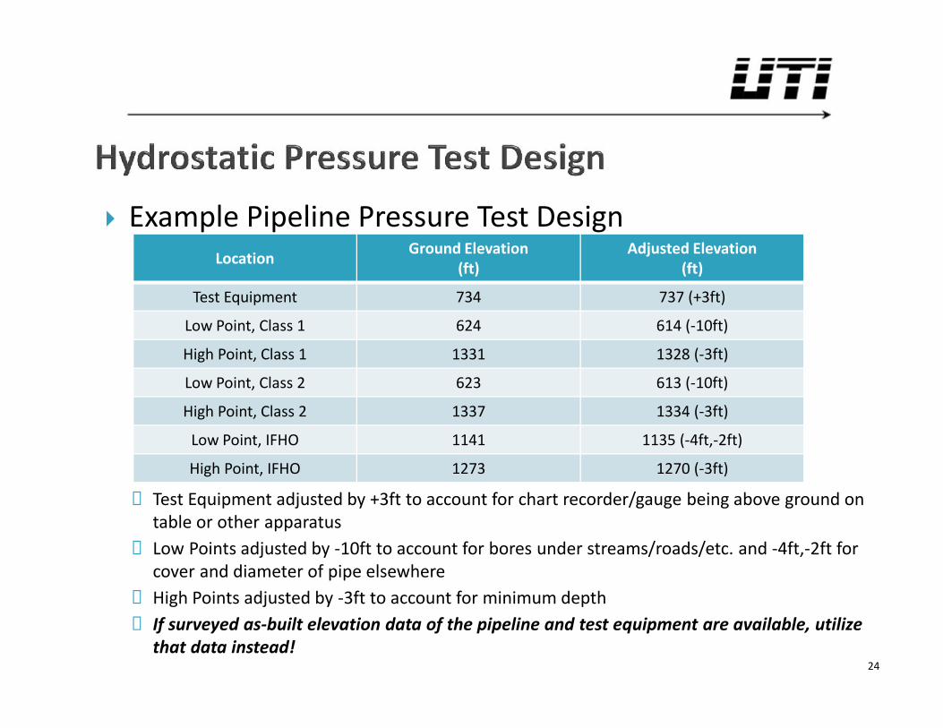
Example Pipeline Pressure Test Design
◦ Test Equipment adjusted by +3ft to account for chart recorder/gauge being above ground ontable or other apparatus
◦ Low Points adjusted by -10ft to account for bores under streams/roads/etc. and -4ft,-2ft forcover and diameter of pipe elsewhere
◦ High Points adjusted by -3ft to account for minimum depth◦ If surveyed as-built elevation data of the pipeline and test equipment are available, utilize
that data instead!24
Location Ground Elevation(ft)
Adjusted Elevation(ft)
Test Equipment 734 737 (+3ft)
Low Point, Class 1 624 614 (-10ft)
High Point, Class 1 1331 1328 (-3ft)
Low Point, Class 2 623 613 (-10ft)
High Point, Class 2 1337 1334 (-3ft)
Low Point, IFHO 1141 1135 (-4ft,-2ft)
High Point, IFHO 1273 1270 (-3ft)
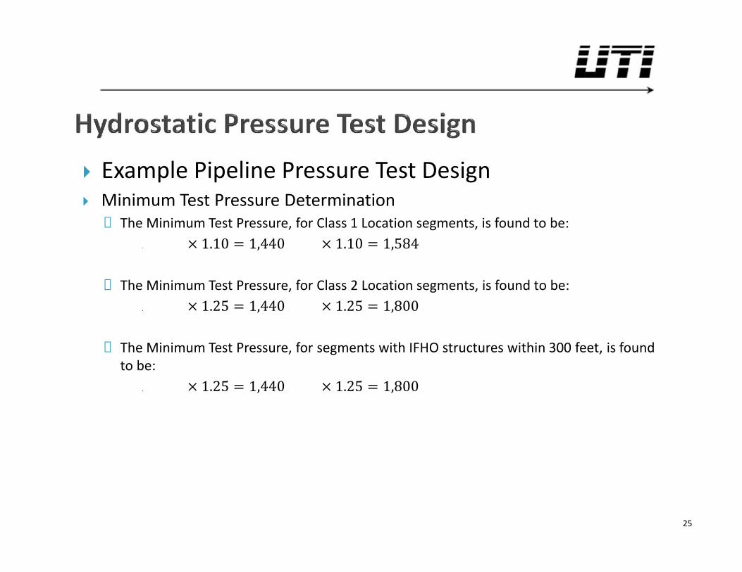
Example Pipeline Pressure Test Design Minimum Test Pressure Determination
◦ The Minimum Test Pressure, for Class 1 Location segments, is found to be:× 1.10 = 1,440 × 1.10 = 1,584◦ The Minimum Test Pressure, for Class 2 Location segments, is found to be:× 1.25 = 1,440 × 1.25 = 1,800◦ The Minimum Test Pressure, for segments with IFHO structures within 300 feet, is found
to be: × 1.25 = 1,440 × 1.25 = 1,800
25
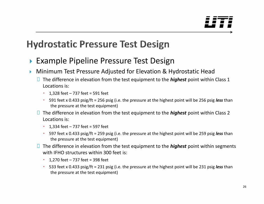
Example Pipeline Pressure Test Design Minimum Test Pressure Adjusted for Elevation & Hydrostatic Head
◦ The difference in elevation from the test equipment to the highest point within Class 1Locations is: 1,328 feet – 737 feet = 591 feet 591 feet x 0.433 psig/ft = 256 psig (i.e. the pressure at the highest point will be 256 psig less than
the pressure at the test equipment)◦ The difference in elevation from the test equipment to the highest point within Class 2
Locations is: 1,334 feet – 737 feet = 597 feet 597 feet x 0.433 psig/ft = 259 psig (i.e. the pressure at the highest point will be 259 psig less than
the pressure at the test equipment)◦ The difference in elevation from the test equipment to the highest point within segments
with IFHO structures within 300 feet is: 1,270 feet – 737 feet = 398 feet 533 feet x 0.433 psig/ft = 231 psig (i.e. the pressure at the highest point will be 231 psig less than
the pressure at the test equipment)
26
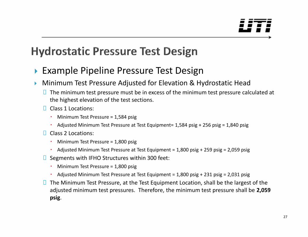
Example Pipeline Pressure Test Design Minimum Test Pressure Adjusted for Elevation & Hydrostatic Head
◦ The minimum test pressure must be in excess of the minimum test pressure calculated atthe highest elevation of the test sections.
◦ Class 1 Locations: Minimum Test Pressure = 1,584 psig Adjusted Minimum Test Pressure at Test Equipment= 1,584 psig + 256 psig = 1,840 psig
◦ Class 2 Locations: Minimum Test Pressure = 1,800 psig Adjusted Minimum Test Pressure at Test Equipment = 1,800 psig + 259 psig = 2,059 psig
◦ Segments with IFHO Structures within 300 feet: Minimum Test Pressure = 1,800 psig Adjusted Minimum Test Pressure at Test Equipment = 1,800 psig + 231 psig = 2,031 psig
◦ The Minimum Test Pressure, at the Test Equipment Location, shall be the largest of theadjusted minimum test pressures. Therefore, the minimum test pressure shall be 2,059psig.
27
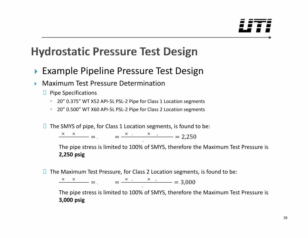
Example Pipeline Pressure Test Design Maximum Test Pressure Determination
◦ Pipe Specifications 20” 0.375” WT X52 API-5L PSL-2 Pipe for Class 1 Location segments 20” 0.500” WT X60 API-5L PSL-2 Pipe for Class 2 Location segments
◦ The SMYS of pipe, for Class 1 Location segments, is found to be:× × = = × . × ,. = 2,250The pipe stress is limited to 100% of SMYS, therefore the Maximum Test Pressure is2,250 psig
◦ The Maximum Test Pressure, for Class 2 Location segments, is found to be:× × = = × . × ,. = 3,000The pipe stress is limited to 100% of SMYS, therefore the Maximum Test Pressure is3,000 psig
28
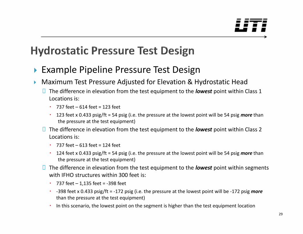
Example Pipeline Pressure Test Design Maximum Test Pressure Adjusted for Elevation & Hydrostatic Head
◦ The difference in elevation from the test equipment to the lowest point within Class 1Locations is: 737 feet – 614 feet = 123 feet 123 feet x 0.433 psig/ft = 54 psig (i.e. the pressure at the lowest point will be 54 psig more than
the pressure at the test equipment)◦ The difference in elevation from the test equipment to the lowest point within Class 2
Locations is: 737 feet – 613 feet = 124 feet 124 feet x 0.433 psig/ft = 54 psig (i.e. the pressure at the lowest point will be 54 psig more than
the pressure at the test equipment)◦ The difference in elevation from the test equipment to the lowest point within segments
with IFHO structures within 300 feet is: 737 feet – 1,135 feet = -398 feet -398 feet x 0.433 psig/ft = -172 psig (i.e. the pressure at the lowest point will be -172 psig more
than the pressure at the test equipment) In this scenario, the lowest point on the segment is higher than the test equipment location
29
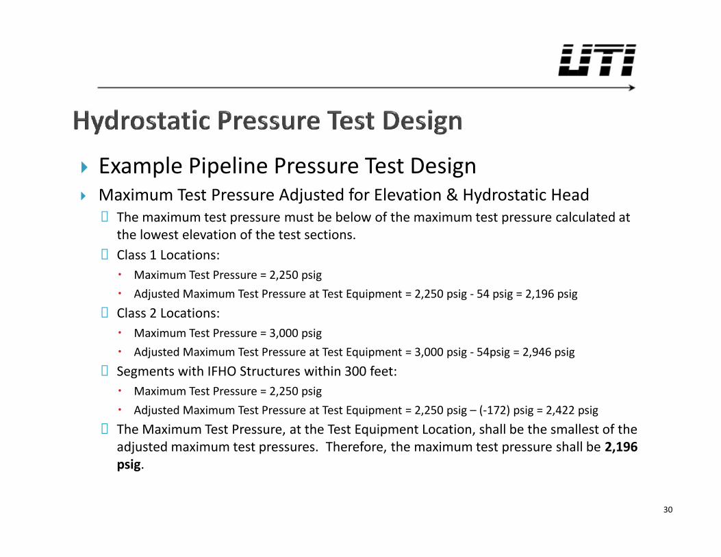
Example Pipeline Pressure Test Design Maximum Test Pressure Adjusted for Elevation & Hydrostatic Head
◦ The maximum test pressure must be below of the maximum test pressure calculated atthe lowest elevation of the test sections.
◦ Class 1 Locations: Maximum Test Pressure = 2,250 psig Adjusted Maximum Test Pressure at Test Equipment = 2,250 psig - 54 psig = 2,196 psig
◦ Class 2 Locations: Maximum Test Pressure = 3,000 psig Adjusted Maximum Test Pressure at Test Equipment = 3,000 psig - 54psig = 2,946 psig
◦ Segments with IFHO Structures within 300 feet: Maximum Test Pressure = 2,250 psig Adjusted Maximum Test Pressure at Test Equipment = 2,250 psig – (-172) psig = 2,422 psig
◦ The Maximum Test Pressure, at the Test Equipment Location, shall be the smallest of theadjusted maximum test pressures. Therefore, the maximum test pressure shall be 2,196psig.
30
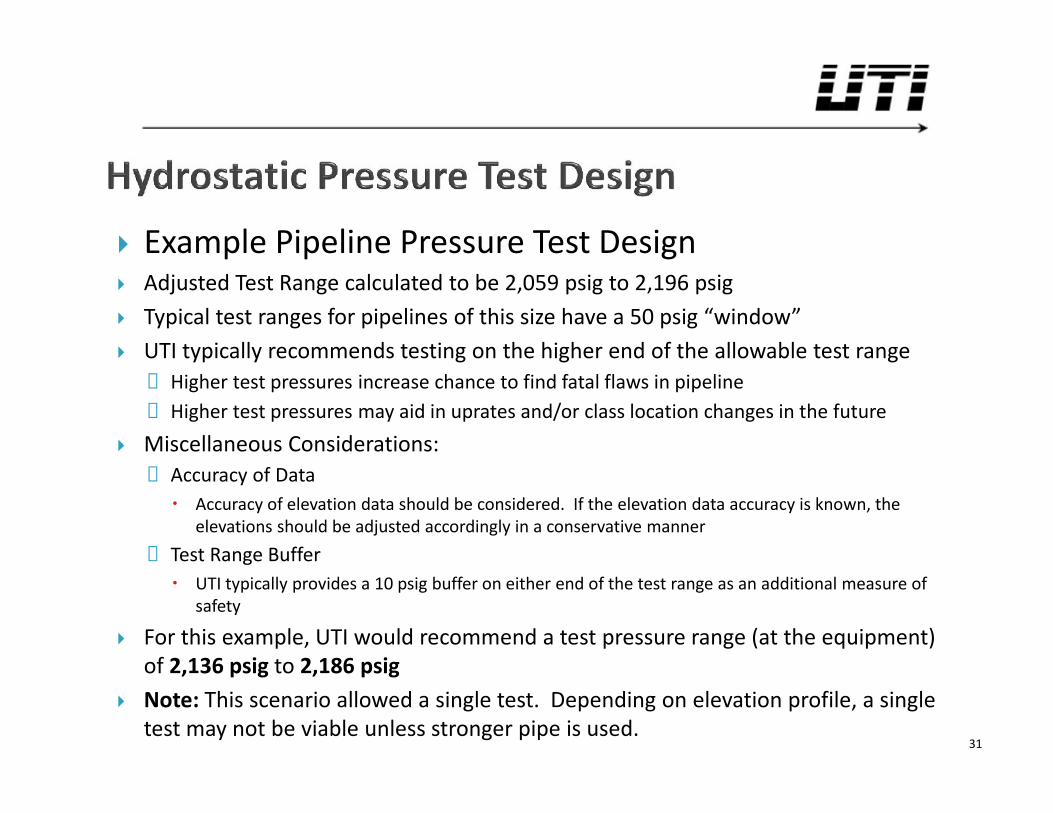
Example Pipeline Pressure Test Design Adjusted Test Range calculated to be 2,059 psig to 2,196 psig Typical test ranges for pipelines of this size have a 50 psig “window” UTI typically recommends testing on the higher end of the allowable test range
◦ Higher test pressures increase chance to find fatal flaws in pipeline◦ Higher test pressures may aid in uprates and/or class location changes in the future
Miscellaneous Considerations:◦ Accuracy of Data Accuracy of elevation data should be considered. If the elevation data accuracy is known, the
elevations should be adjusted accordingly in a conservative manner◦ Test Range Buffer UTI typically provides a 10 psig buffer on either end of the test range as an additional measure of
safety
For this example, UTI would recommend a test pressure range (at the equipment)of 2,136 psig to 2,186 psig
Note: This scenario allowed a single test. Depending on elevation profile, a singletest may not be viable unless stronger pipe is used.
31
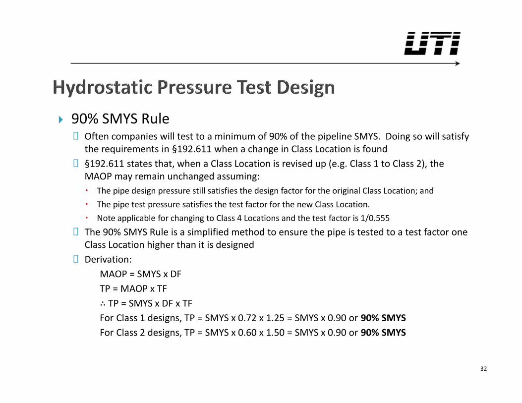
90% SMYS Rule◦ Often companies will test to a minimum of 90% of the pipeline SMYS. Doing so will satisfy
the requirements in §192.611 when a change in Class Location is found◦ §192.611 states that, when a Class Location is revised up (e.g. Class 1 to Class 2), the
MAOP may remain unchanged assuming: The pipe design pressure still satisfies the design factor for the original Class Location; and The pipe test pressure satisfies the test factor for the new Class Location. Note applicable for changing to Class 4 Locations and the test factor is 1/0.555
◦ The 90% SMYS Rule is a simplified method to ensure the pipe is tested to a test factor oneClass Location higher than it is designed
◦ Derivation:MAOP = SMYS x DFTP = MAOP x TF∴ TP = SMYS x DF x TFFor Class 1 designs, TP = SMYS x 0.72 x 1.25 = SMYS x 0.90 or 90% SMYSFor Class 2 designs, TP = SMYS x 0.60 x 1.50 = SMYS x 0.90 or 90% SMYS
32
Spike Hydrostatic Testing◦ Resulted from findings that hydrostatic testing is not effective in exposing
defects along the circumference of the pipe (Michael Baker Jr., Inc., 2004)◦ Additional measure for operators to expose defects in pipelines◦ Not required by, nor does it directly satisfy 49 CFR Part 192◦ Typical pressure test range of 100% to 110% of SMYS◦ Typical duration of one (1) hour per AGA and CEPA (Canadian Energy Pipeline
Association). ASME recommends only ten (10) minutes.
33
UTI’s Method for Test Design◦ UTI utilizes a proprietary spreadsheet for calculating test ranges◦ Allows for input of pipe/fitting/PRC specifications, elevations, etc.◦ Greatly increases the speed of test design process◦ Reduces potential for human error in test calculations, etc.◦ Provides a neat, orderly form for records◦ Greatly simplifies process of test design for complex pipelines with multiple
classes, pipe specifications, and fittings/flanges/valves
34
Filling & Dewatering Pipelines◦ Filling Filling the pipeline with water should be done slowly and in a controlled manner to
eliminate any shock to the system and remove any trapped air. Often pigs are pushed ahead to keep the water column intact to prevent mixing. The water can, especially on large diameter and/or long pipelines, take hours or days to
stabilize. Often a chart is placed on the test header during fill to observe the stabilization. Water should be clean and free of debris. Depending on source & quality, water may
require chemical treatment. Pressure up in stages to reduce shock to system. Allow to stabilize (overnight, when
possible).
35
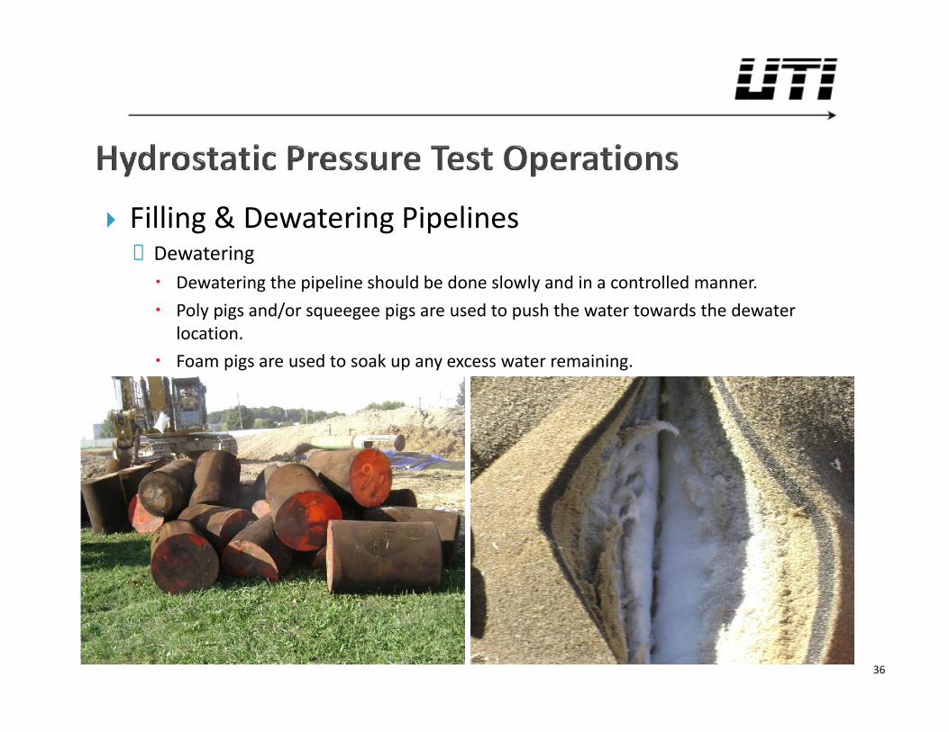
Filling & Dewatering Pipelines◦ Dewatering Dewatering the pipeline should be done slowly and in a controlled manner. Poly pigs and/or squeegee pigs are used to push the water towards the dewater
location. Foam pigs are used to soak up any excess water remaining.
36
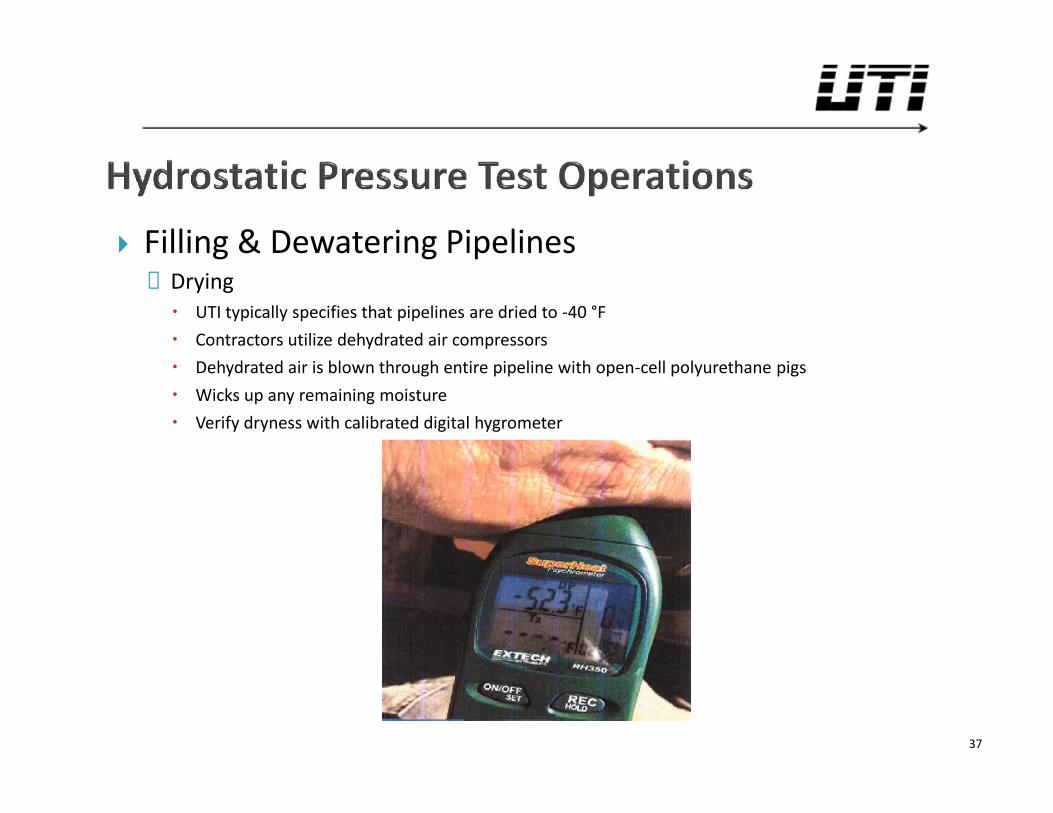
Filling & Dewatering Pipelines◦ Drying UTI typically specifies that pipelines are dried to -40 °F Contractors utilize dehydrated air compressors Dehydrated air is blown through entire pipeline with open-cell polyurethane pigs Wicks up any remaining moisture Verify dryness with calibrated digital hygrometer
37
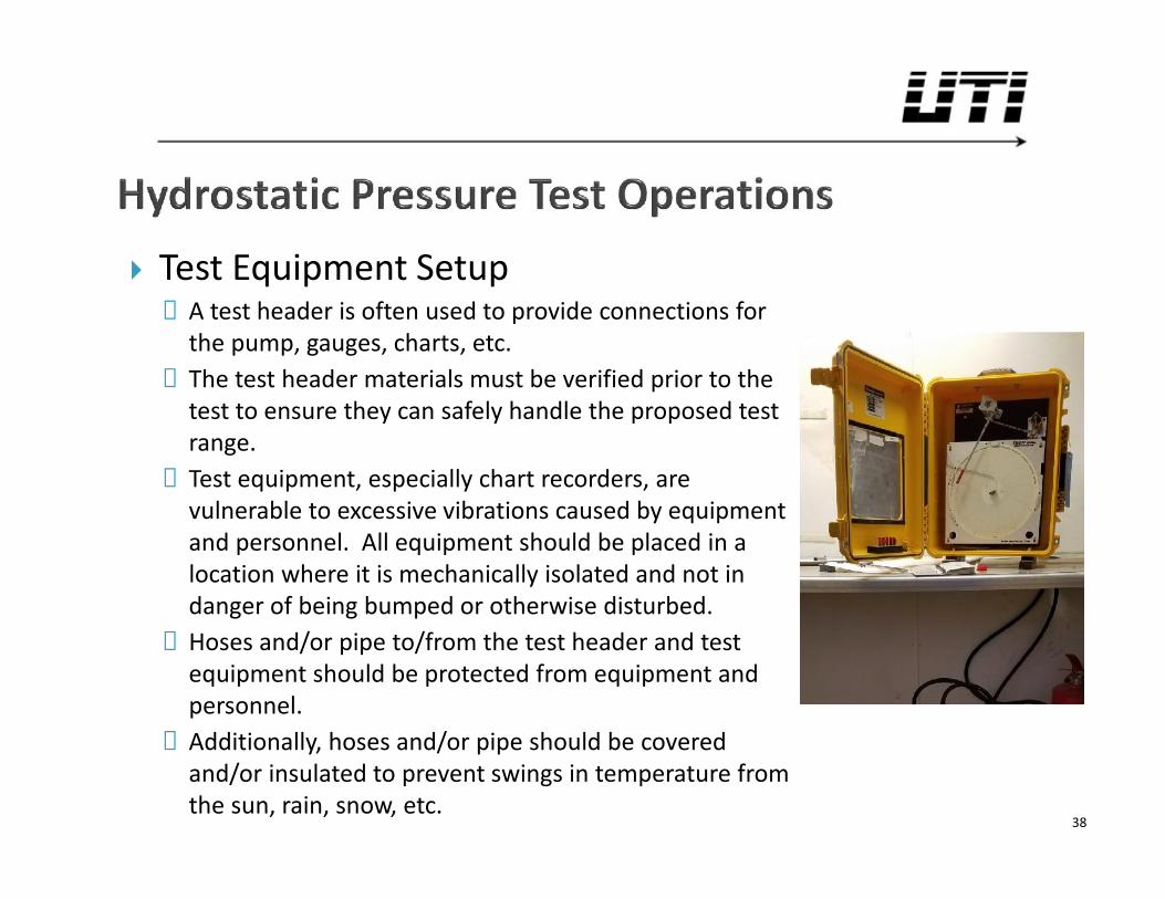
Test Equipment Setup◦ A test header is often used to provide connections for
the pump, gauges, charts, etc.◦ The test header materials must be verified prior to the
test to ensure they can safely handle the proposed testrange.
◦ Test equipment, especially chart recorders, arevulnerable to excessive vibrations caused by equipmentand personnel. All equipment should be placed in alocation where it is mechanically isolated and not indanger of being bumped or otherwise disturbed.
◦ Hoses and/or pipe to/from the test header and testequipment should be protected from equipment andpersonnel.
◦ Additionally, hoses and/or pipe should be coveredand/or insulated to prevent swings in temperature fromthe sun, rain, snow, etc.
38
Test Preparation◦ Verify test equipment location matches that shown on the test design◦ Verify pipe, fittings, flanges, valves, etc. in test Must match those described on test design Stop operation if material to be tested does not match test design
◦ Verify all equipment calibrations and retain copies Serial numbers must match calibration records Calibration dates must be within acceptable time range
◦ Verify all equipment is in good working order with new batteries, if applicable◦ Verify all equipment is connected properly◦ Step up pressure on pipeline, to the target test pressure, in multiple sections Hold after each step to allow stabilization and check for leaks Number of step ups and hold times are dependent on size of pipeline, among other
factors◦ Step up to final target test pressure and disconnect all pumps◦ Begin test
39
Test Operation◦ UTI typically records pressure and temperature readings in fifteen minute
increments Readings are relayed in real time to engineering and operations groups for continuous
monitoring If any issues arise, they may be corrected or the test restarted immediately rather than
delaying until the end of the test◦ Inspectors and/or contractors should check for leaks at various times
throughout the test Check all visible locations, especially threaded and bolted connections Frequency of leak checks should be determined by the operator
◦ Pumping and/or bleeding of pressure should not be permitted without approvaland detailed documentation as to the reason
◦ Upon completion but prior to depressurizing, inspectors send pressure readingsand photos of charts to engineering and operations to verify test completenessand validity
40
Test Acceptance◦ In order to accept a hydrostatic pressure test, the following items should
be considered: Test chart and/or pressure gauge depict pressures within the test range for a
continuous eight (8) hours All equipment calibration records are current and accounted for No leaks were found, per §192.503(a)(2) Any rise or fall in pressure must be able to be directly attributed to temperature,
weather, precipitation, etc. (i.e. not a leak) In cases where pressure drops are thought to be attributed to temperature, UTI’s
senior management and the client review all data and make the final determination(i.e. not inspection or contractors)
If no determination can be justified, the test may be extended until the pressure isobserved to continuously and consistently rise (as temperatures increase)
UTI has found some operators will make a determination of no leaks if the testpressure is found to not fall over a continuous one (1) hour period. This could befollowed up with a leak survey after commissioning as additional assurance.
41
Documentation & Record Keeping◦ Test records are the pedigree of the pipeline!◦ Per §192.517(a), “Each operator shall make, and retain for the useful life of the
pipeline, a record of each test performed…”◦ Per the same section, the operator must retain the following information, at a
minimum: The operator's name, the name of the operator's employee responsible for making the
test, and the name of any test company used Test medium used Test pressure Test duration Pressure recording charts, or other record of pressure readings Elevation variations, whenever significant for the particular test Leaks and failures noted and their disposition
42
Documentation & Record Keeping◦ In addition, UTI recommends keeping the following records, where applicable Test equipment calibration records Test equipment makes and models Dates and times of readings Sign off from company, inspector, contractor, and engineering Notes of type of weather experienced and any noticeable affects on the test Drawings and/or detailed description of what was tested (especially when pipelines or
facilities are tested in multiple segments and breakpoints are not obvious)
43
Water Supply & Disposal◦ Water from municipal water supplies ideal given high quality Permit or agreement typically required
◦ Water from streams, ponds, etc. may introduce silt, sand, debris, and bacteria Permit may be required (e.g. ODNR water withdrawal permit) Debris can be strained out prior to introduction to pipeline Presence of bacteria requires chemical treating
◦ Water discharged overland or back into streams Permit typically required (e.g. OEPA Hydrostatic Discharge Permit #OH000002 Water must be collected and tested Requirements differ for new pipelines vs. used pipelines
Environmental controls required to eliminate erosion◦ Water discharged to tanks and disposed of off site Water must be disposed of at approved site Can be less expensive and quicker process on smaller jobs
44
Communication◦ Personnel on site should have readily available means of communication with all other
personnel involved◦ Examples include radios, cellphones, line-of-sight, etc.
Boundaries & Barriers◦ Barriers, tape, fencing, etc. should be erected around the test area◦ Stage personnel and/or erect signs at all points of ingress along the pipeline to warn of
the test/restrict access◦ All non-essential personnel and the public should be kept at a safe distance◦ Only essential personnel should be allowed in the test area and should only remain there
as needed to safely and effectively operate the test.◦ In special circumstances, equipment may be used to act as a barrier between the test
area and nearby structures
General Safety◦ Keep equipment in good, safe operating condition◦ Keep hoses, pipes, etc. out of traveled areas, covered, or well marked to avoid tripping
hazards
45
TOTAL CAPABILITIES IN THE PIPELINE INDUSTRY
UTILITY TECHNOLOGIES INTERNATIONAL CORPORATIONwww.uti-corp.com
QUESTIONS?