Offshore Wind Turbines supported by monopiles - … og doktoroppgaver/Thesis defence... · Offshore...
44
Offshore Wind Turbines supported by monopiles Installation Technology, a Passive Damper, and a Study on the Breaking Wave Induced Vibrations PhD thesis defense, UiS, 21 st June, 2013 Arunjyoti Sarkar PhD Student, UiS Prof. Ove T. Gudmestad Advisor, UiS Prof. Daniel Karunakaran Advisor, UiS / Subsea 7
Transcript of Offshore Wind Turbines supported by monopiles - … og doktoroppgaver/Thesis defence... · Offshore...
Offshore Wind Turbines supported by monopiles
Installation Technology, a Passive Damper, and a Study on the Breaking Wave Induced Vibrations
PhD thesis defense, UiS, 21st June, 2013
Arunjyoti Sarkar
PhD Student, UiS
Prof. Ove T. Gudmestad Advisor, UiS
Prof. Daniel Karunakaran Advisor, UiS / Subsea 7
Marine Operations for Offshore Wind Turbine
Sequence of presentation
1. Background: current technical challenges and towards solution – research questions
2. Installation of monopile: existing method, asociated problems and suggested solution
3. Installation of upper structures: existing methods, associated problems and suggested solution
4. A passive damper concept: theoretical and experimental study
5. Dynamics of an offshore wind turbine in breaking waves
6. Summary
Slide 2
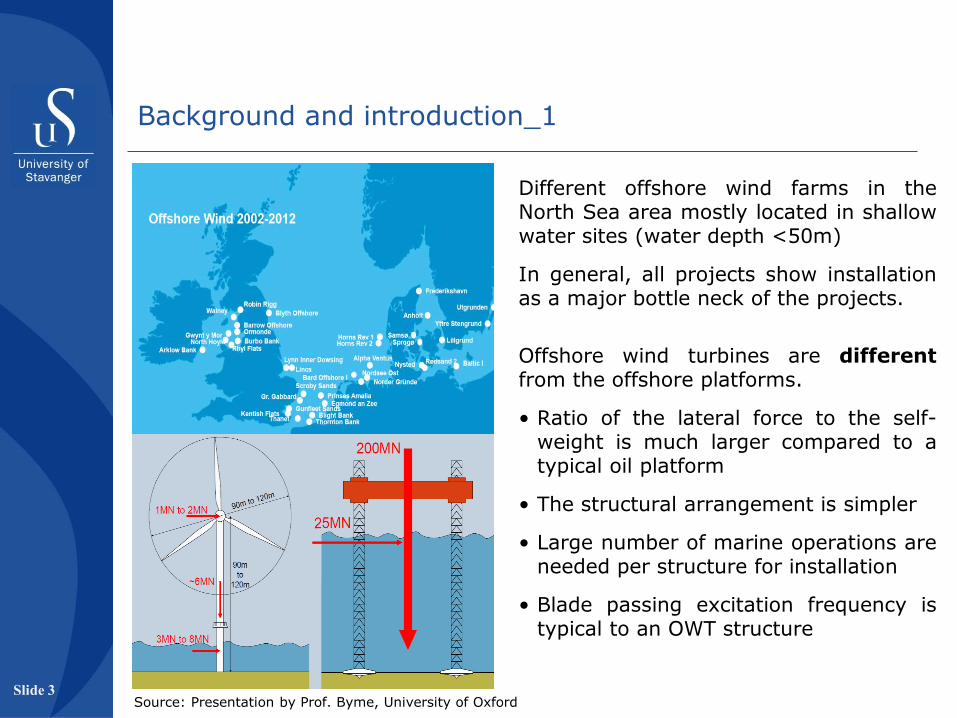
Different offshore wind farms in the North Sea area mostly located in shallow water sites (water depth <50m)
In general, all projects show installation as a major bottle neck of the projects.
Offshore wind turbines are different from the offshore platforms.
• Ratio of the lateral force to the self-weight is much larger compared to a typical oil platform
• The structural arrangement is simpler
• Large number of marine operations are needed per structure for installation
• Blade passing excitation frequency is typical to an OWT structure
Background and introduction_1
Source: Presentation by Prof. Byme, University of Oxford
Slide 3

Offshore Wind Turbines – overview of different components
1. Foundation
2. Transition piece
3. Tower
4. Nacelle
5. Blades
Source: Presentation by Prof. Byme, University of Oxford
Currently, the monopile solution is more attractive compared to others
- widely field proven
- simple geometry to fabricate and to connect with the upper structures
- easier transportation compared to other solutions
Slide 4
Background and introduction_2
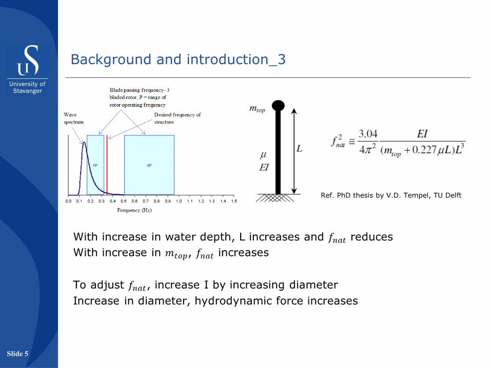
Ref. PhD thesis by V.D. Tempel, TU Delft
Slide 5
Background and introduction_3
Background and introduction_4
Challanges of the current OWT projects
• 40 GW offshore wind energy by 2020 in the EU (baseline scenario).
– This is difficult to achieve with the current installation technology; average time for a single unit installation is large.
(in Dogger Bank, 90 WTGs are installed in 1.5 – 2 years; more than 500 WTGs to be installed in phase 1)
• In future, the problems with existing installation technology will be more as the support structures are expected to be bigger.
– The industry is moving to intermediate water depths (~50m)
– The offshore wind generators are becomming bigger (> 5 MW)
Slide 6

Towards solution
(main considerations)
– Reduce the total number of installation
– Reduce the time required for a single installation
– Increase the weather window by increasing the allowable installation seastate
– Further optimize the support structures for deeper water (~50m)
Background and introduction_5
Slide 7
Background and introduction_6
The goal of this work
To develop new installation method that can reduce number of marine operation. Two operations are considered
(1) installation of a monopile
(2) installation of fully integrated upper structure
To develop new structural general arrangements and installation aids required for the inatallation methodology.
To increase the allowable installation seastate.
To develop a passive damping device that may help to optimise the support structures further in future.
To study the characteristics of breaking wave induced vibrations.
Slide 8
Background and introduction_6
Research methodology
Identifying the reasons for which the existing installation methods provides low operating seastate, and find alternative solutions.
Showing the technical feasibility of the proposed installation methods by numerical analysis.
Developing new structural general arrangements and installation aids required for the inatallation methodology.
Developing a damping device that is a hybrid of a TLCD and a TMD.
Working on a numerical approach to carry out study on the breaking wave induced vibration by using existing tools.
Slide 9
Overview of marine operations for offshore installation
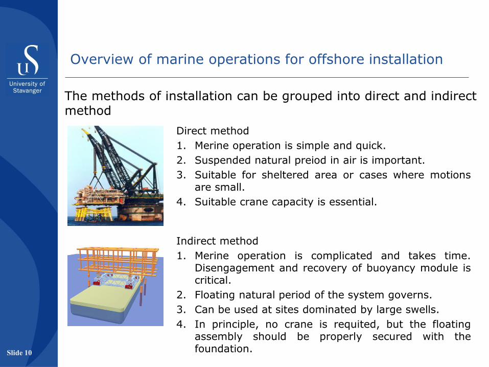
The methods of installation can be grouped into direct and indirect method
Direct method
1. Merine operation is simple and quick.
2. Suspended natural preiod in air is important.
3. Suitable for sheltered area or cases where motions are small.
4. Suitable crane capacity is essential.
Indirect method
1. Merine operation is complicated and takes time. Disengagement and recovery of buoyancy module is critical.
2. Floating natural period of the system governs.
3. Can be used at sites dominated by large swells.
4. In principle, no crane is requited, but the floating assembly should be properly secured with the foundation.
Slide 10

Installation of a monopile
Installation of a monopile by SSIP structure
Objectives:
• To formulate an alternative installation methodology.
• To develop a configuration of the required installation aid.
• To carry out a technical feasibility on the onsite application of the methodology and establish the design requirements of the installation aid.
Slide 12

The existing installation methods mainly use the Jack-up type installation vessel to perform the marine operations.
A jack-up vessel can withstand large seastate when standing on seabed.
During work mode transfer (standing to floating or vice versa), the self-weight quickly passes between leg reaction and buoyancy –> impact load in the lifting mechanism.
The lifting systems are commonly designed to withstand such loads for a seastate of HS 1.5m.
Installation of a monopile – problem of existing approach_1
Slide 13
Source: Tiranr PL, Perol C, Stability and operations of jack-ups
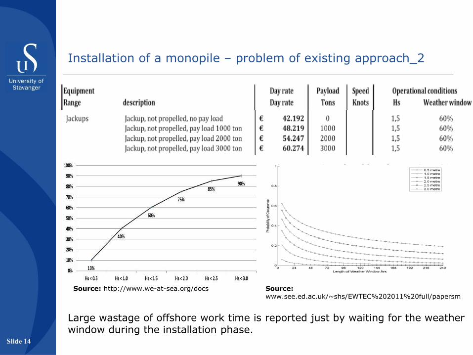
Source: http://www.we-at-sea.org/docs
Large wastage of offshore work time is reported just by waiting for the weather window during the installation phase.
Source: www.see.ed.ac.uk/~shs/EWTEC%202011%20full/papersm
Slide 14
Installation of a monopile – problem of existing approach_2

A floating vessel has 6 rigid body degrees of freedom.
Anchoring firmly with seabed and using DP system can provide sufficient stability.
This approach has been used in Sheringhum Shoal project, allowable installation seastate was low.
At higher water depth, the mooring lines become flexible and the vessel loses the desired stability.
Two possible solutions –
1. Design jack-ups that can withstand 2.5m Hs;
2. Use a floating vessel which don’t have any mode transfer load case.
Option 2 is chosen for this work, as vessels available with O&G industry may be used.
Slide 15
Installation of a monopile – problem of existing approach_3

For a jacket structure, the piles are installed after the jacket rests on the mudmat, either through the legs or the guides. In Alpha Ventus, jackets are placed over pre-installed piles which are driven by using a temporary suvmerged template type structure to get accurate relative position. The suggested solution for monopile installation:
isolation of the marine operations from the vessel by using a template structure, termed as an SSIP structure.
This structure will support the monopile during the initial phase of driving.
Installation of a monopile – other methods
Slide 16
Source: presentation from Norwind installer
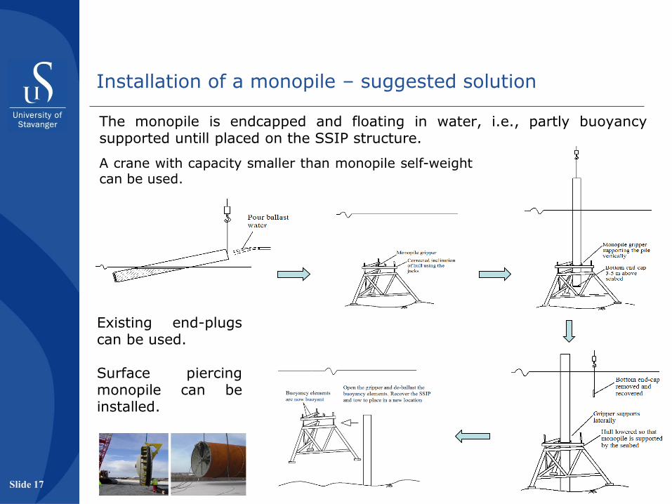
The monopile is endcapped and floating in water, i.e., partly buoyancy supported untill placed on the SSIP structure.
Existing end-plugs can be used. Surface piercing monopile can be installed.
A crane with capacity smaller than monopile self-weight can be used.
Installation of a monopile – suggested solution
Slide 17
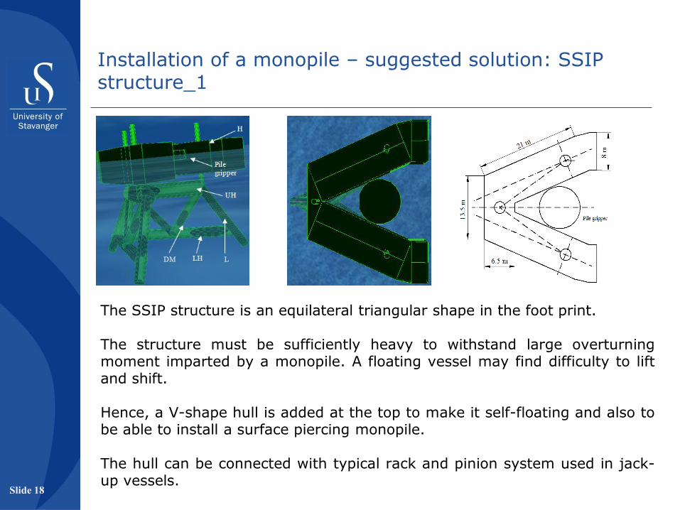
The SSIP structure is an equilateral triangular shape in the foot print. The structure must be sufficiently heavy to withstand large overturning moment imparted by a monopile. A floating vessel may find difficulty to lift and shift. Hence, a V-shape hull is added at the top to make it self-floating and also to be able to install a surface piercing monopile. The hull can be connected with typical rack and pinion system used in jack-up vessels.
Installation of a monopile – suggested solution: SSIP structure_1
Slide 18

The standing mode is checked in RIFLEX, two critical load cases are identified.
Case 1: when pile’s self weight supported by SSIP
Case 2: when pile’s self weight is transferred to seabed and SSIP provides only lateral support.
The lateral support is modelled by roller contact surface option in RIFLEX.
• Analysis inputs: Seabed - stiff clay, C = 250 kPa Footing – circular type Monopile - Ø6.0m, L60m Water depth - 50m Seastate – 2.5m Hs (JONSWAP spectrum) Current - 1.0 m/s throughout the water depth • For structural check, API-RP-2A and AISC manual for
steel construction have been used.
Installation of a monopile – suggested solution: SSIP structure_2
Slide 19
Observations:
The SSIP can be used to install a monopile at 2.5m Hs from a floating vessel in the North Sea area. Overturning moment and the sliding bearing capacity are the main design challenge. The diagonal members need to be grouted to increased the self-weight of the structure to resist the overturning moment. Existing end-caps can be directly used in this methodology. The configuration presented here is suitable for 50m water depth. For higher / lower water depth, a different configuration is required. Disadvantage of the method is that the marine operation will be irreversible. A possible contingency operation should be considered. Overall complexity in this method is more, but the benifit is expected from the gain in weather window and reduction in the average installation time.
Installation of a monopile – suggested solution: SSIP structure_3
Slide 20
Installation of a fully integrated upper strutcure
(FIUS)
Objectives:
• To formulate a possible configuration of an FIUS suitable for the installation methodology.
• To formulate an installation methodology for an FIUS on a foundation.
• To develop a configuration of the required installation aid.
• To carry out a technical feasibility on the onsite application of the methodology and establish the design requirements of the installation aid.
Slide 21
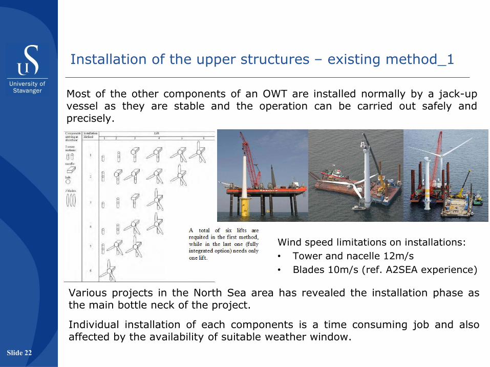
Most of the other components of an OWT are installed normally by a jack-up vessel as they are stable and the operation can be carried out safely and precisely.
Various projects in the North Sea area has revealed the installation phase as the main bottle neck of the project.
Individual installation of each components is a time consuming job and also affected by the availability of suitable weather window.
Installation of the upper structures – existing method_1
Wind speed limitations on installations:
• Tower and nacelle 12m/s
• Blades 10m/s (ref. A2SEA experience)
Slide 22

A fully integrated option has been attempted in the Beatrice project.
The allowable installation seastate was low and the option was found to be unattractive.
Since, a large mass is located at the top of the tower, floating stability of such a fully integrated system is sensitive.
Installation of the upper structures – existing method_2
Slide 23

A float-over method is an indirect method which is used to install large topside structures in verious projects.
Such an approach can be beneficial if a fully integrated system can be made sufficiently stable by adding external buoyancy.
A telescopic tower can be used to lower the COG of the structure which will provide realistic demand on the external buoyancy to be used.
Orientation of the blades is essential to avoid hudrodynamic loading on the blades.
Installation of the upper structures – other methods
Gudmestad et al. 2009
Slide 24
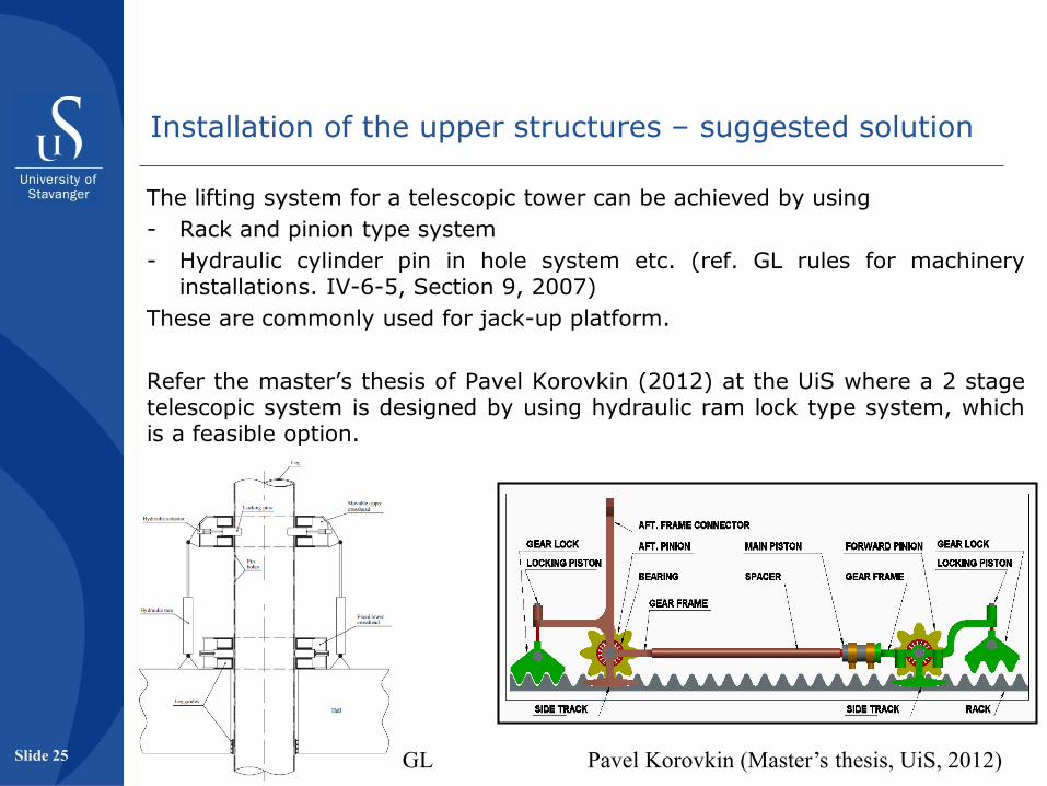
The lifting system for a telescopic tower can be achieved by using
- Rack and pinion type system
- Hydraulic cylinder pin in hole system etc. (ref. GL rules for machinery installations. IV-6-5, Section 9, 2007)
These are commonly used for jack-up platform.
Refer the master’s thesis of Pavel Korovkin (2012) at the UiS where a 2 stage telescopic system is designed by using hydraulic ram lock type system, which is a feasible option.
GL Pavel Korovkin (Master’s thesis, UiS, 2012)
Installation of the upper structures – suggested solution
Slide 25
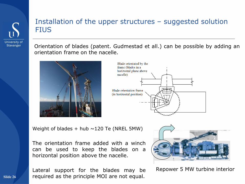
Orientation of blades (patent. Gudmestad et all.) can be possible by adding an orientation frame on the nacelle.
Repower 5 MW turbine interior
Weight of blades + hub ~120 Te (NREL 5MW)
The orientation frame added with a winch can be used to keep the blades on a horizontal position above the nacelle.
Lateral support for the blades may be required as the principle MOI are not equal.
Installation of the upper structures – suggested solution FIUS
Slide 26
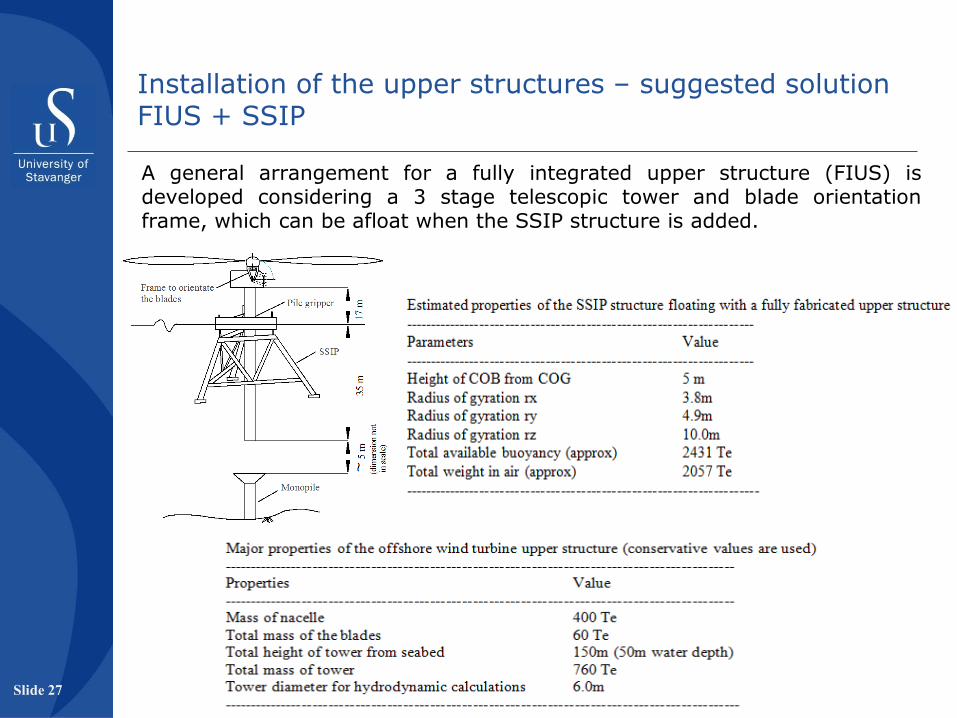
A general arrangement for a fully integrated upper structure (FIUS) is developed considering a 3 stage telescopic tower and blade orientation frame, which can be afloat when the SSIP structure is added.
Installation of the upper structures – suggested solution FIUS + SSIP
Slide 27
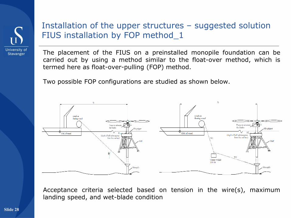
The placement of the FIUS on a preinstalled monopile foundation can be carried out by using a method similar to the float-over method, which is termed here as float-over-pulling (FOP) method. Two possible FOP configurations are studied as shown below.
Installation of the upper structures – suggested solution FIUS installation by FOP method_1
Acceptance criteria selected based on tension in the wire(s), maximum landing speed, and wet-blade condition
Slide 28

Observations:
An FIUS can be installed by the FOP method at a seastate of Hs 2.5m in the North Sea area. The large hull of the SSIP attracts significant amount of hydrodynamic loading. The effect of mutual motion of the two floating bodies affects the chance of slack. Adding a clump weight in the wire reduces the chance of slack wire. Addition of a designed shoch absorber is important as the maximum landing speed is larger than assumed allowable speed (0.2 m/s) Winch speed is not modelled here. The winch in heave compensation mode can be used for a softer landing of the structure. All results of the SSIP for installing a monopile and a FIUS structure is summarized in Appended paper 4.
Installation of the upper structures – suggested solution FIUS installation by FOP method_2
Slide 29

A passive damper device
Pendulum type liquid column damper (PLCD)
Objectives:
• To develop a new passive damping concept which can be used where the space is constrained, and tuning can be easier.
• To formulate the mathematical model of the damper.
• To fabricate a physical model in the labiratory and carry out experimental studies.
• To validate the mathematical model.
Slide 30
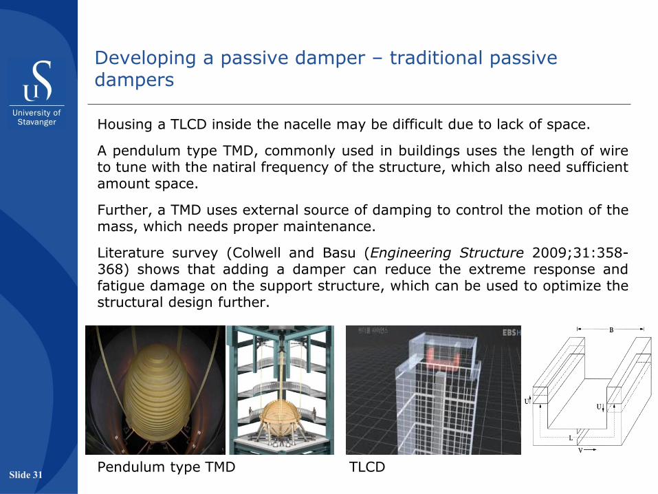
Housing a TLCD inside the nacelle may be difficult due to lack of space.
A pendulum type TMD, commonly used in buildings uses the length of wire to tune with the natiral frequency of the structure, which also need sufficient amount space.
Further, a TMD uses external source of damping to control the motion of the mass, which needs proper maintenance.
Literature survey (Colwell and Basu (Engineering Structure 2009;31:358-368) shows that adding a damper can reduce the extreme response and fatigue damage on the support structure, which can be used to optimize the structural design further.
Pendulum type TMD TLCD
Developing a passive damper – traditional passive dampers
Slide 31
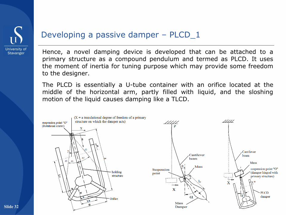
Hence, a novel damping device is developed that can be attached to a primary structure as a compound pendulum and termed as PLCD. It uses the moment of inertia for tuning purpose which may provide some freedom to the designer.
The PLCD is essentially a U-tube container with an orifice located at the middle of the horizontal arm, partly filled with liquid, and the sloshing motion of the liquid causes damping like a TLCD.
Developing a passive damper – PLCD_1
Slide 32
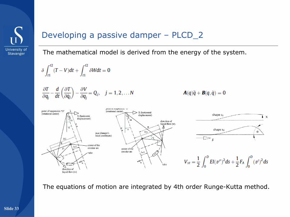
The mathematical model is derived from the energy of the system.
Developing a passive damper – PLCD_2
The equations of motion are integrated by 4th order Runge-Kutta method.
Slide 33
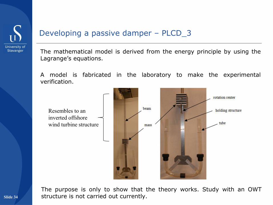
The mathematical model is derived from the energy principle by using the Lagrange’s equations.
A model is fabricated in the laboratory to make the experimental verification.
The purpose is only to show that the theory works. Study with an OWT structure is not carried out currently.
Resembles to an
inverted offshore
wind turbine structure
Developing a passive damper – PLCD_3
Slide 34

Good agreement between the theoretical and experimental results validates the mathematical model.
Developing a passive damper – PLCD_4
Slide 35
Detailed results in Appended paper 5:
Sarkar A, Gudmestad OT. Pendulum type liquid column damper (PLCD) for controlling vibrations of a structure – Theoretical and experimental study. Engineerig Structures 2013;49:221-233.
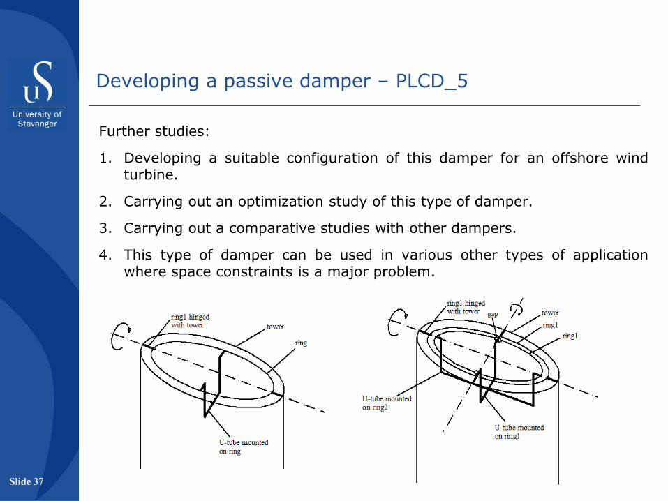
Further studies:
1. Developing a suitable configuration of this damper for an offshore wind turbine.
2. Carrying out an optimization study of this type of damper.
3. Carrying out a comparative studies with other dampers.
4. This type of damper can be used in various other types of application where space constraints is a major problem.
Developing a passive damper – PLCD_5
Slide 37

Dynamics of a 5MW OWT strutcure under the actions of breaking waves and wind
Objectives:
• To study the dynamic characteristics of an offshore wind turbine under the action of breaking wave impact load for
(a) with and without aerodynamic damping
(b) with fixed and flexible foundation
(c) with zero wind speed and operating wind speed
• To use a more accurate approach to estimate the breaking wave induced forces
• To use the existing softwares to carry out the study Slide 38

Breaking waves can excite large vibration in an OWT structure at a shallow water site.
The purpose of this study is to find out how the structure behaves in such a load case (DAF, max acceleration at the nacelle etc.), and whether a review of the design approach is required.
Studying the dynamics of an offshore wind turbine numerically is the so-called aero-hydro-servo-elastic problem.
Modelling the whole problem (breaking wave + wind) in a single CFD software will be time consuming for a large sensitivity study.
Here, it is carried out in two stages.
1. First the breaking wave induced hydrodynamic force on a vertical pile (Ø 6.0m) is estimated separately in a CFD model by Mr. Sung-Jin Choi (UiS/DNV).
2. These forces are then applied in an OWT model in HAWC2 (Risø, Denmark) through a dll program to study the dynamic response of the structure.
Dynamics of a 5MW OWT strutcure under the actions of breaking waves and wind_1
Slide 39

Contribution from Mr. Choi
• Developing the necessary tools to carry out studies on the shallow water waves by using a Navier-Stoke’s solver.
• Validating the same by comparing with the results obtained from tests carried out on a 0.7m diameter vertical pile in the Hannover University.
• Estimating the impact forces on a monopile (Ø6.0m) by using the same CFD tool for wave height 10.4 m and period 11.3 s (plunging breaker)
These time series are then applied on an OWT structure modelled in HAWC2 using a dll interface written in FORTRAN.
Dynamics of a 5MW OWT strutcure under the actions of breaking waves and wind_2
Slide 40
The study is carried out for three foundation assumptions, which are:
1. Fixed at the seabed
2. Fixed at a depth two times the pile diameter below the seabed
3. Flexible foundation modelling the pile-soil interaction by using the p-y curves (following API-RP-2A WSD). HAWC2 provides facility to model lateral springs.
Dynamics of a 5MW OWT strutcure under the actions of breaking waves and wind_3
Slide 41
The study is carried out for three wind states, which are:
1. No aerodynamic damping and no wind
2. With aerodynamic damping and no wind (zero wind speed)
3. With aerodynamic damping and wind speed of 8.0 m/s.
Resultant damping without aerodynamic damping ~1%
Resultant damping with aerodynamic damping ~ 0.23 (log decreement)
These are in the range of values presented in literature (ref. Appended paper 6)
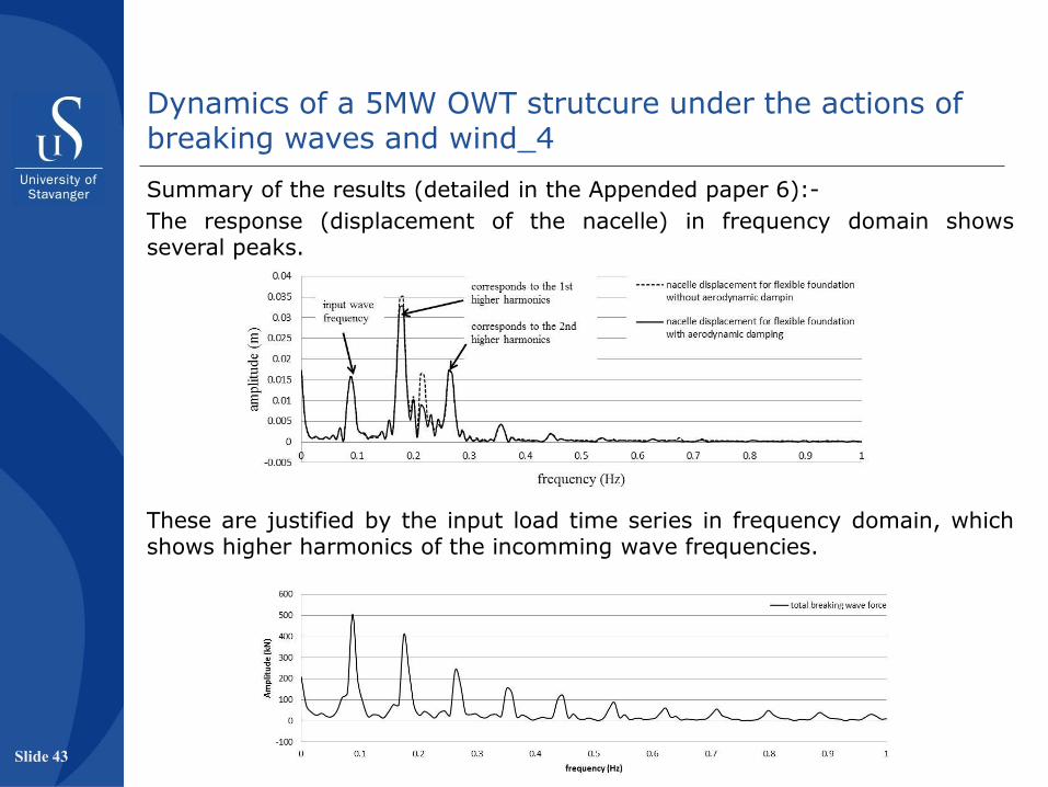
These are justified by the input load time series in frequency domain, which shows higher harmonics of the incomming wave frequencies.
Summary of the results (detailed in the Appended paper 6):-
The response (displacement of the nacelle) in frequency domain shows several peaks.
Dynamics of a 5MW OWT strutcure under the actions of breaking waves and wind_4
Slide 43
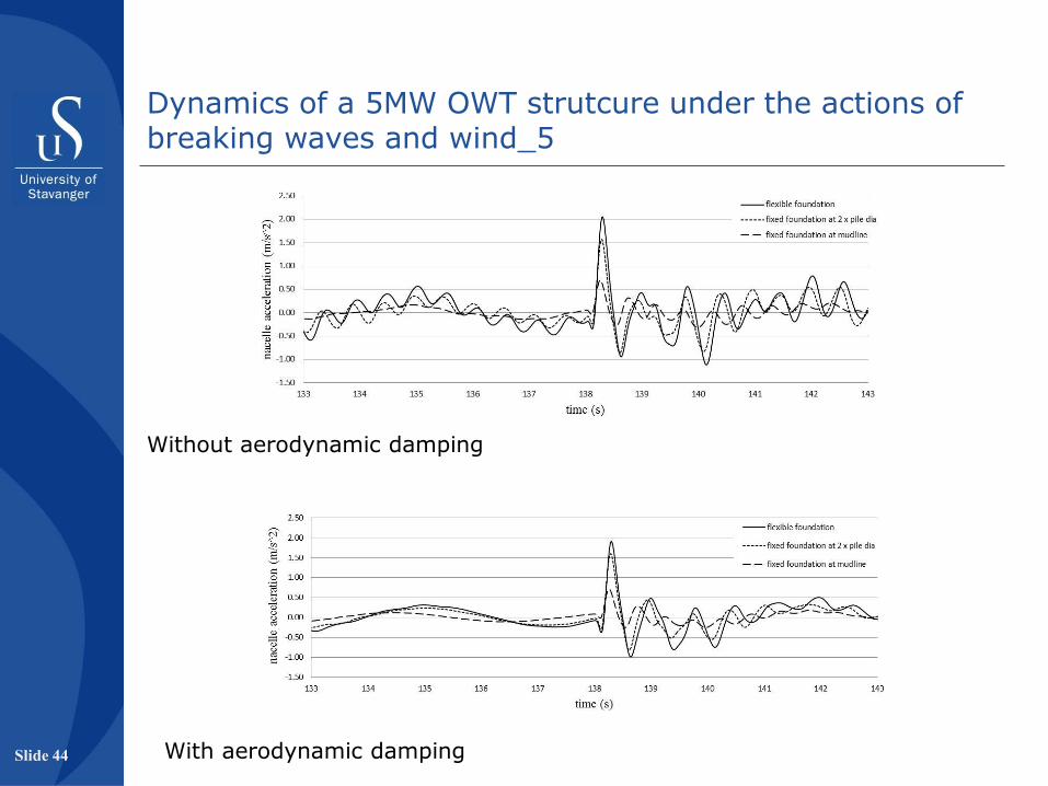
Without aerodynamic damping
With aerodynamic damping
Dynamics of a 5MW OWT strutcure under the actions of breaking waves and wind_5
Slide 44

Ovservations:
1. The individual slamming duration is very small compared to the natural frequency of an OWT structure supported by monopile. Hence, large DAF within the load duration is not expected.
(here, tn = 4.34s, tp = 0.207s)
2. It the second peak coincides with the structure’s frequency, the response will be larger.
3. The structure’s response at the nacelle increases for a flexible foundation compared to a foundation fixed foundations.
4. Aerodynamic damping is not large enough to reduce the peak response.
5. Maximum nacelle acceleration is estimated to be 2.0 m/s2. This will increase if the condition at point 2 occures.
Dynamics of a 5MW OWT strutcure under the actions of breaking waves and wind_6
Slide 45

• A submerged support structure can be used to instal a monopile at a higher seastate compared to the existing installation methods.
• Float-over method can be adopted to instal a fully integrated upper structure along with a telescopic tower and a blade orientation frame
• A passive damping device derived from the configuration of a TMD and a TLCD can be usefull to reduce the response of a cantilever strutcure.
• Higher harminiocs present in repeated breaking waves are expected to cause resonating vibration in an offshore wind turbine, producing large acceleration at the nacelle level. Hence, it is advisable to avoid sites where breaking wave porbability exists.
Summary
Slide 46

Thank you