OFFHAND GRINDING OF TOOLS AND SELECTION …astakhov.tripod.com/MC/Grinding-Selection.pdfCHAPTER 5...
24
CHAPTER 5 OFFHAND GRINDING OF TOOLS AND SELECTION OF CARBIDE TOOLING CHAPTER LEARNING OBJECTIVES Upon completing this chapter, you should be familiar with the following: Identify and explain the use of grinding equipment. Identify and explain the use of grinding wheels. Identify and explain the use of single-point cutting tools. Identify and explain the use of carbide tools One requirement for advancement in the MR rating is the ability to grind and sharpen some of the tools used in the machine shop. The equipment used for this purpose includes bench, pedestal, carbide, and chip breaker grinders and precision grinding machines. This chapter explains the use of these grinders and how to grind small tools by using the offhand grinding technique. (We’ll cover precision grinding machines in a later chapter.) In grinding, you use the cutting action of an abrasive to remove metal. In offhand grinding you hold the workpiece in your hand and position it against the grinding surface. You must have experience and practice to do this accurately and safely. You also must know how to install grinding wheels on pedestal and bench grinders and how to sharpen or dress them. Before you can properly grind small handtools, single-edged cutting tools, and twist drills, you must know the terms used to describe their angles and surfaces. You also must know the composition of the material from which each tool is made and the operations for which the tool is used. Advancing technology has made carbides the dominate cutting tool in machine shops. You must understand carbide terminology and the use of carbide tools. GRINDING SAFETY The grinding wheel is a fragile cutting tool that operates at high speeds. Therefore, the safe operation of bench and pedestal grinders is as important as proper grinding techniques. Follow all posted safety precautions. Review your equipment operators manual for other safety precautions and any chapters of Navy Occupational Safety and Health (NAVOSH) Program Manual for Forces Afloat, OPNAV Instruction 5100.19B, that apply to the equipment. BENCH AND PEDESTAL GRINDERS Bench grinders (fig. 5-1) are small, self-contained, and usually mounted on a workbench. Use them to grind and sharpen small tools such as lathe, planer, Figure 5-1.—Bench grinder. 5-1
Transcript of OFFHAND GRINDING OF TOOLS AND SELECTION …astakhov.tripod.com/MC/Grinding-Selection.pdfCHAPTER 5...
CHAPTER 5
OFFHAND GRINDING OF TOOLSAND SELECTION OF CARBIDE TOOLING
CHAPTER LEARNING OBJECTIVES
Upon completing this chapter, you should be familiar with the following:
Identify and explain the use of grinding equipment.
Identify and explain the use of grinding wheels.
Identify and explain the use of single-point cutting tools.
Identify and explain the use of carbide tools
One requirement for advancement in the MRrating is the ability to grind and sharpen some of thetools used in the machine shop. The equipment usedfor this purpose includes bench, pedestal, carbide, andchip breaker grinders and precision grindingmachines. This chapter explains the use of thesegrinders and how to grind small tools by using theoffhand grinding technique. (We’ll cover precisiongrinding machines in a later chapter.)
In grinding, you use the cutting action of anabrasive to remove metal. In offhand grinding youhold the workpiece in your hand and position itagainst the grinding surface. You must haveexperience and practice to do this accurately andsafely. You also must know how to install grindingwheels on pedestal and bench grinders and how tosharpen or dress them.
Before you can properly grind small handtools,single-edged cutting tools, and twist drills, you mustknow the terms used to describe their angles andsurfaces. You also must know the composition of thematerial from which each tool is made and theoperations for which the tool is used.
Advancing technology has made carbides thedominate cutting tool in machine shops. You mustunderstand carbide terminology and the use of carbidetools.
GRINDING SAFETY
The grinding wheel is a fragile cutting tool thatoperates at high speeds. Therefore, the safe operationof bench and pedestal grinders is as important asproper grinding techniques. Follow all posted safetyprecautions. Review your equipment operatorsmanual for other safety precautions and any chaptersof Navy Occupational Safety and Health (NAVOSH)Program Manual for Forces Afloat, OPNAVInstruction 5100.19B, that apply to the equipment.
BENCH AND PEDESTAL GRINDERS
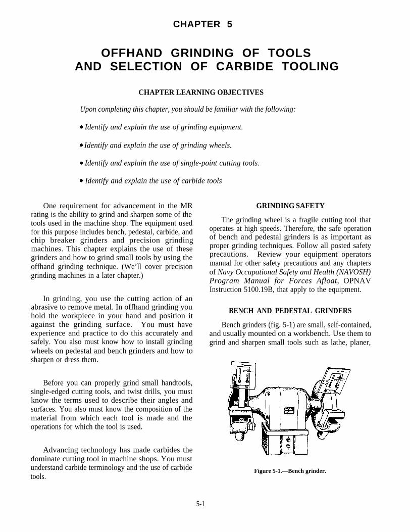
Bench grinders (fig. 5-1) are small, self-contained,and usually mounted on a workbench. Use them togrind and sharpen small tools such as lathe, planer,
Figure 5-1.—Bench grinder.
5-1

and shaper cutting tools; twist drills; and handtoolssuch as chisels and center punches. These grinders donot have installed coolant systems; however, acontainer of water is usually mounted on the front ofthe grinder.
Bench grinders usually have grinding wheels upto 8 inches in diameter and 1 inch thick. A wheelguard encircles the grinding wheel except for thework area. An adjustable toolrest steadies theworkpiece. You can move it in or out or swivel it toadjust to grinding wheels of different diameters. Anadjustable eyeshield made of safety glass should bemounted on the upper part of the wheel guard.Position this shield to deflect the grinding wheelparticles away from you.
Pedestal grinders (fig. 5-2) are usually heavy-duty bench grinders mounted on a pedestal fastened tothe deck. They usually have the features of a benchgrinder plus a coolant system, which includes a pump,storage sump, hose, and fittings to regulate and carrythe coolant to the wheel surface.
GRINDING WHEELS
A grinding wheel is made of two basic elements:(1) the abrasive grains, and (2) the bonding agent.You can think of the abrasive grains as many
28 .61
Figure 5-2.—Grinding on a pedestal grinder. Figure 5-3.—Grinding wheel shapes.
single-point tools embedded in a toolholder orbonding agent. Each of these grains removes a verysmall chip from the workpiece as it makes contact oneach revolution of the grinding wheel.
An ideal cutting tool is one that will sharpen itselfwhen it becomes dull. This, in effect, happens to theabrasive grains. As the individual grains become dull,the pressure on them causes them to fracture andpresent new sharp cutting edges to the work. Whenthe grains can fracture no more, the pressure becomestoo great and they are released from the bond,allowing a new layer of sharp grains to contact thework.
SIZES AND SHAPES
The size of a grinding wheel is determined by itsdiameter in inches, the diameter of its spindle hole,and the width of its face. Grinding wheels have toomany shapes to list in this manual, but figure 5-3shows those used most often. The type numbers arestandard and all manufacturers use them. The shapesare shown in cross-sectional views. The job willdictate the shape you should use.
WHEEL MARKINGS AND COMPOSITION
Grinding wheel markings are composed of sixstations, each of which identifies a characteristic of
5-2

Figure 5-4.—Standard marking system for grinding wheels (except diamond).
the wheel. Since different grinding jobs require differentabrasives, you should learn this identification systemso you can identify the grinding wheel you need for agiven job. The six stations are (1) type of abrasive,(2) grain size, (3) bond grade, (4) structure, (5) type ofbond, and (6) the manufacturer’s record symbol.Figure 5-4 shows the six stations that identify nearlyall abrasives except diamond, which we’ll explain inlater paragraphs. Follow the stations in the figurefrom left to right as you read an explanation of eachstation in the following paragraphs:
1. Type of abrasive: There are two types ofabrasives: natural and manufactured. Naturalabrasives, such as emery, corundum, and diamond,are used only in honing stones and in special types ofgrinding wheels. The common manufacturedabrasives are aluminum oxide and silicon carbide.They have superior qualities and are more economicalthan natural abrasives. Aluminum oxide (designatedby the letter A in station 1) is used to grind steel andsteel alloys and for heavy duty work such as to clean
up steel castings. Silicon carbide (designated by theletter C in station 1) is harder but not as tough asaluminum oxide. It’s used mostly to grind nonferrousmetals and carbide tools. The abrasive in a grindingwheel makes up about 40 percent of the wheel.
2. Grain size: Grain sizes range from 10 to 500.The size is determined by the size of mesh of a sievethrough which the grains can pass. Grain size is ratedas follows: coarse: 10, 12, 14, 16, 18, 20, 24;medium: 30, 36, 46, 54, 60; fine: 70, 80, 90, 100, 120,150, 180; and very fine: 220, 240, 280, 320, 400, 500,600. Fine grain wheels are preferred to grind hardmaterials-they have more cutting edges and will cutfaster than coarse grain wheels. Coarse grain wheelsare generally preferred to remove metal quickly fromsofter materials.
3. Bond grade (hardness): The bond grade runsfrom A to Z, (soft to hard). It’s a measure of thebond’s ability to hold the abrasive grains in the wheel.A grade of soft or hard does not mean that the bond or
5-3

the abrasive is soft or hard; it means that the wheel haseither a small amount of bond (soft grade) or a largeamount of bond (hard grade). Figure 5-5 showsmagnified portions of both soft-grade and hard-gradewheels. You can see that a part of the bond surroundsthe abrasive grains, and the remainder of the bondforms into posts that hold the grains to the wheel andhold them apart from each other. The wheel with thelarger amount of bonding material (hard grade) hasthick bond posts and offers great resistance togrinding pressures. The wheel with the least amountof bond (soft grade) offers less resistance.
4. Structure: The structure is designated bynumbers from 1 to 15. It refers to the open spacebetween the grains, as shown in figure 5-5. Wheelswith grains that are very closely spaced are said to bedense; when grains are wider apart, the wheels aresaid to be open. Open-grain wheels will remove moremetal faster than close-grain wheels. Also, dense, orclose grain, wheels normally produce a finer finish.Structure makes up about 20 percent of the grindingwheel.
5. Bond type: The bond makes up the remaining40 percent of the grinding wheel and is one of its mostimportant parts. The bond determines the strength ofthe wheel. The five basic types of bond are vitrified,silicate, rubber, resinoid, and shellac. We willdescribe each of them in the following paragraphs:
Vitrified bond is designated by the letter V.About 75 percent of all grinding wheels are made withvitrified bond. It is not affected by oil, acid, or water.Vitrified bond wheels are strong and porous, and rapidtemperature changes have little effect on them.Vitrified bond is composed of special clays. Whenheated to approximately 2300°F, the clays form aglasslike cement. Do NOT run vitrified bond wheelsfaster than 6,500 surface feet per minute (sfpm).
Silicate bond is designated by the letter S. Thisbond is made of silicate of soda. Silicate bond wheelsare used mainly on large, slow rpm machines where acooler cutting action is wanted. Silicate bond wheelsare softer than vitrified wheels, and they release thegrains more readily. Silicate bond wheels are heatedto approximately 500°F when they are made. Likethe vitrified bond wheel, do not run this one at a speedgreater than 6,500 sfpm.
Rubber bond wheels are designated by theletter R. The bond consists of rubber with sulphuradded as a vulcanizing agent. The bond is made intoa sheet into which the grains are rolled. The wheel is
Figure 5-5.—How bond affects the grade of the wheel. WheelA, softer; wheel B, harder.
stamped out of this sheet and heated in a pressurizedmold until the vulcanizing action is complete. Thesewheels are very strong and elastic, and they are usedas thin cutoff wheels. They produce a high finish andyou can run them at speeds between 9,500 and 16,000sfpm.
Resinoid bond wheels are designated by theletter B. Resinoid bond is made from powdered orliquid resin with a plasticizer added. The wheels arepressed and molded to size and fired at approximately320°F. The wheels are shock resistant and verystrong and they are used for rough grinding and ascutoff wheels. Like rubber bond wheels, you can runthese wheels at a speed of 9,500 to 16,000 sfpm.
Shellac bond wheels are designated by theletter E. They are made from a secretion from Lacbugs. The abrasive and bond are mixed, molded toshape, and baked at approximately 300°F. Shellacbond wheels give a high finish and have a cool cuttingaction when used as cutoff wheels. You also can runthese wheels at speeds between 9,500 and 12,500sfpm.
6. Manufacturer’s Record Symbol: The sixthstation of the grinding wheel marking is the manu-facturer’s record. This may be a letter or number, orboth. The manufacturer uses it to designate bondmodifications or wheel characteristics.
5-4

DIAMOND WHEELS
Diamond grinding wheels are classed bythemselves. They can be made from natural ormanufactured diamonds, and they are very expensive.Their cutting speeds range from 4,500 to 6,000surface feet per minute. Use them with care and onlyto grind carbide cutting tools. They are markedsimilarly to aluminum-oxide and silicon-carbidewheels, although there is not a standard system. Theusual diamond abrasive wheel identification systemuses seven stations as follows:
1. Type of abrasive, designated D for natural andSD for manufactured.
2. Grit size, which can range from 24 to 500. A100-grain size might be used for rough work,and a 220 for finish work. In a Navy machineshop, you might find a 150-grain wheel anduse it for both rough and finish grinding.
3. Grade, designated by letters of the alphabet.
4. Concentration, designated by numbers. Theconcentration, or proportion of diamonds tobond, might be numbered 25, 50, 75, or 100,going from low to high.
5. Bond type, designated B for resinoid, M formetal, and V for vitrified.
6. Bond modification (This station may or maynot be used).
7. Depth of the diamond section. This is thethickness of the abrasive layer and rangesfrom 1/32 to 1/4 inch. Cutting speeds rangefrom 4,500 to 6,000 surface feet per minute.
GRINDING WHEEL SELECTIONAND USE
You should select a grinding wheel that has theproper abrasive, grain, grade, and bond for the job.Base your selection on such factors as the physicalproperties of the material to be ground, the amount ofstock to be removed (depth of cut), the wheel speedand work speed, and the finish required.
To grind carbon and alloy steel, high-speed steel,cast alloys and malleable iron, you probably shoulduse an aluminum oxide wheel. Silicon carbide is themost suitable for nonferrous metals, nonmetallicmaterials, and cemented carbides.
Generally, you’ll choose coarser grain wheels togrind softer and more ductile materials. Also use
coarse-grain wheels to remove a large amount ofmaterial (except on very hard materials). If you needa good finish, use a fine grain wheel. If the machineyou are using is worn, you may need to use a hardergrade wheel to offset the effects of that wear. Youalso can use harder grade wheel if you use a coolantwith it. Refer to your machine’s operators manual toselect grinding wheels for various operations.
Figure 5-6 shows the type of grinding wheel usedon bench and pedestal grinders. When you replacethe wheel, be sure the physical dimensions of the newwheel are correct for the grinder. Check the outsidediameter, the thickness, and the spindle hole. Ifnecessary, use an adapter (bushing) to decrease thesize of the spindle hole so it fits your grinder.
You should use A3605V (coarse) and A60M5V(fine or finish) wheels to grind or sharpen single pointtool bits such as those for a lathe, planer, or shapermade from high-carbon or high-speed steel. Use anA46N5V wheel for stellite tools. These wheels havealuminum oxide as an abrasive material; use them togrind steel and steel alloys only. If you use them oncast iron, nonferrous metal, or nonmetallic materials,you may load or pin the wheel when particles of thematerial are imbedded in the wheel’s pores. Thisstrains the wheel and could cause it to fail andpossibly injure someone.
WHEEL INSTALLATION
You must install the wheel of a bench or pedestalgrinder properly or it will not operate properly andmay cause accidents. Before you install a wheel,inspect it for visible defects and “sound” it to learn ifit has invisible cracks.
To sound a wheel, hold it up by placing a hammerhandle or a short piece of cord through the spindlehole. Use a nonmetallic object such as a screwdriverhandle or small wooden mallet to tap the wheel lightlyon its side. Rotate the wheel 1/4 of a turn (90°) andrepeat the test. A good wheel will give out a clearringing sound. If you hear a dull thud, the wheel iscracked and should not be used.
Figure 5-6.—Grinding wheel for bench and pedestal grinders.
5-5

Figure 5-7.—Method of mounting a grinding wheel.
Look at figure 5-7 as you read the followingexplanation about wheel installation. Note thatblotters are used on both sides of a wheel. A blotterensures even pressure on the wheel and dampens thevibration between the wheel and the shaft. A paperblotter may be no more than 0.0025 inch thick and aleather or rubber blotter no more than 0.125 inch.
1. Be sure the shaft and flanges are clean and freeof grit and old blotter material. Place the inner flangein place and follow it with a blotter.
2. Mount the wheel against the inner blotter andbe sure it fits on the shaft without play. There shouldbe a 0.002- to 0.005-inch clearance. You may need toscrape or ream the lead bushing in the center of thewheel to get this clearance. NEVER FORCE THEWHEEL ONTO THE SHAFT. You may force thewheel out of axial alignment or cause it to crack whenit is used.
3. Install the second blotter, followed by theouter flange. Note that the flanges are recessed sothey provide an even pressure on the wheel. Theflanges should be at least one-third the diameter of thewheel.
4. Install the washer and secure the nut. Tightenthe nut enough to hold the wheel firmly; if you tightenit too much, you may damage the wheel.
TRUING AND DRESSING THE WHEEL
Grinding wheels, like other cutting tools, requirefrequent reconditioning of cutting surfaces to performefficiently. Dressing is the process of cleaning theircutting faces. This cleaning breaks away dullabrasive grains and smooths the surface so that thereare no grooves. Truing is the removal of materialfrom the cutting face of the wheel so that the surfaceruns absolutely true to some other surface such as thegrinding wheel shaft.
Use the wheel dresser shown in figure 5-8 to dressgrinding wheels on bench and pedestal grinders. Todress a wheel with this tool, start the grinder and let itcome up to speed. Set the wheel dresser on the rest asshown in figure 5-8 and bring it in firm contact withthe wheel. Move the wheel dresser across theperiphery of the wheel until the surface is clean andapproximately square with the sides of the wheel.
Several things can get a grinding wheel out ofbalance. For instance, it may be out of round, and youcan usually correct the problem by dressing thewheel. Or, it may get out of balance if part of thewheel is immersed in coolant. If this happens,remove the wheel and bake it dry. If the wheel getsout of balance axially, it probably will not affect theefficiency of the wheel on bench and pedestalgrinders. To correct axial unbalance, remove thewheel and clean the shaft spindle, the hole, and theflanges.
Figure 5-8.—Using a grinding wheel dresser.
5-6

WHEEL CARE AND STORAGE
It’s easy to damage or break grinding wheels ifyou mishandle them or store them improperly.Whenever you handle them, take care not to dropthem or bump them against other hard objects.
Store grinding wheels in a cabinet or on shelveslarge enough to allow selection of a wheel withoutdisturbing the other wheels. The storage space shouldprotect against high humidity, contact with liquids,freezing temperatures, and extreme temperaturechanges. Also secure grinding wheels aboard ship toprevent them from being damaged when the ship is atsea. Stack thin cutoff wheels on a rigid surfacewithout any separators or blotters between them.Stack flaring cup wheels flat with the small endstogether. Store all other types of wheels upright ontheir rims with blotters between them. A sheet metalcabinet lined with felt or corrugated cardboard toprevent wheel chipping makes good storage.
CARBIDE TOOL GRINDER
The carbide tool grinder (fig. 5-9) looks muchlike a pedestal grinder with the toolrest on the sideinstead of the front. The main components of thecarbide tool grinder are a motor with the shaftextended at each end to mount the grinding wheels,the pedestal that supports the motor and is fastened tothe deck, wheel guards mounted around the
Figure 5-9.—Carbide tool grinder.
circumference and back of the grinding wheels as asafety device, and an adjustable toolrest mounted infront of each wheel to support the tool bits while theyare being ground.
While you grind on the periphery of the wheel ona pedestal grinder, you will grind on the side of thewheel on a carbide tool bit grinder. The straight cupwheel (fig. 5-10) is similar to the wheels used on mostcarbide tool bit grinders. Some carbide tool grindershave a straight cup wheel on one side of the grinderand a straight wheel, such as the type used on apedestal or bench grinder, on the other side.
The adjustable toolrest has an accurately groundgroove or keyway across the top of its table. Thisgroove holds a protractor attachment that you can setto the desired cutting edge angle. The toolrest willalso adjust to permit grinding the relief angle.
If your carbide tool grinder has a coolant system,be sure you direct an ample, steady stream of coolantat the point where the tool meets the wheel. Anirregular flow may allow the tool to heat up and thenbe quenched quickly.your grinder has nocool in the air; do NOT dip it in water when itbecomes hot.
which may crack the carbide. Ifcoolant system, let the carbide
Carbide-tipped tool bits may have either disposableor brazed cutting edges. The disposable-tip tool bitneeds no sharpening; just dispose of the tips whentheir cutting edges become dull. Sharpen thebrazed-tip tool bit on the carbide tool bit grinder.
For best results with carbide-tipped tool bits, usea silicon-carbide wheel for roughing and a diamondimpregnated wheel for finishing.
Figure 5-10.—Crown on the working face of a wheel for acarbide tool bit grinder.
5-7

Figure 5-11.—Chip breaker grinder.
CHIPBREAKER GRINDER
A chip breaker grinder (fig. 5-11) is a specializedgrinding machine. It grinds grooves or indentationson the top surface of carbide tools to control thedirection and length of the chips produced in cuttingmetal. Later in this chapter, we’ll describe the typesof chip breakers that are commonly ground on carbidetools.
The chip breaker grinder has a vise you can adjustto four different angles to hold the tool to be ground.These angles are the side cutting edge, back rake, siderake, and chip breaker, and we’ll explain them later inthis chapter. The vise is mounted so you can move itback and forth under the grinding wheel. Both thecross feed used to position the tool under the grindingwheel and the vertical feed used to control the depthof the chip breaker are graduated in increments of0.001 inch.
The chip breaker grinder uses a diamond wheel.It is usually a type 1 straight wheel but differs fromother type 1 wheels because it is normally less than
1/4 inch thick. An SD150R100B grinding wheel isnormally recommended.
Chip breaker grinders have a coolant system thateither floods or slowly drips coolant onto the toolbeing ground. The main objective is to prevent thegrinding wheel from loading up or glazing over fromthe grinding operation.
CUTTING TOOL MATERIALS
The materials used to make machine cutting toolsmust be hard enough to cut other metals, be wearresistant, have impact strength to resist fracture, andkeep their hardness and cutting edge at hightemperatures. Several different materials are used forcutting tools, and each one has properties differentfrom the others. Selection of a cutting tool materialdepends upon the metal to be cut and the conditionsunder which it will be cut.
HIGH-SPEED STEEL
High-speed steel is a widely used cutting toolmaterial. High-speed steel tools can maintain theirhardness and abrasion resistance under the hightemperatures and pressures generated during thegeneral cutting process. Although the hardness of ahigh-speed tool (Rc 60-70) is not much greater thanthat of carbon-steel tools, high-speed steel begins tolose its hardness at a tempering temperature of 1,000°to 1,100°F. Machine shops generally use two types ofhigh-speed tools: tungsten high-speed steel andmolybdenum high-speed steel. These designationsshow the major alloying element in each of the twotypes. Both types resist abrasive wear, remain hard athigh temperatures, and keep a similar degree ofhardness. The molybdenum high-speed steel istougher than the tungsten and is more effective inmachinery operations where interrupted cuts aremade. In an interrupted cut, such as cuttingout-of-round or slotted material, the cutter contactsthe material many times in a short period of time.This “hammering” effect dulls or breaks cutters thatare not tough enough to withstand the shock effect.
CAST ALLOYS
Cast alloy tool steel usually contains varyingamounts of cobalt, chrome, tungsten, and molybdenum.Tools made from these steels are generally moreefficient than tools made from high-speed steel,retaining their hardness up to an operating tempera-ture of approximately l,400°F. This characteristic
5-8

allows cutting speeds approximately 60 percentgreater than for high-speed steel tools. However, castahoy tools are not as tough as the high-speed steeltools and they cannot bear the same cutting stresses,such as interrupted cuts. Clearances ground on castalloy cutting tools are less than those ground onhigh-speed steel tools because of the lower degree oftoughness. Tools made from this metal are generallyknown as Stellite, Rexalloy, and Tantung.
CEMENTED CARBIDE
A carbide, generally, is a chemical compound ofcarbon and metal. The term commonly refers tocemented carbides, the cutting tools made of tungstencarbide, titanium carbide, or tantalum carbide, andcobalt in various combinations. A typical compositionof cemented carbide is 85 to 95 percent carbides oftungsten and the remainder a cobalt binder for thetungsten carbide powder.
Cemented carbides are made by compressingvarious metal powders and sintering (heating to weldparticles together without melting them) thebriquettes. Cobalt powder is used as a binder for thecarbide powder.
Carbides have greater hardness at both high andlow temperatures than high-speed or cast alloys. Attemperatures of 1,400°F and higher, carbides maintainthe hardness required for efficient machining. Thismakes possible machining speeds of approximately400 fpm in steels. The addition of tantalum increasesthe red hardness of a tool material. Cementedcarbides are extremely hard tool materials (aboveRc90), have a high compressive strength, and resistwear and rupture.
Cemented carbides are the most widely used toolmaterial in the machining industry. They areparticularly useful for cutting tough alloy steels thatquickly break down high-speed tool steels. Variouscarbide grades and insert shapes are available and youshould make the correct selection to machine aparticular material. We’ll now briefly discussbrazed-on tip carbides. Since mechanically-held tip(insert type) carbides are more widely used, we willdiscuss them in more depth later in the chapter.
Brazed-on Tip
The brazed-on carbide-tip cutting tool was thefirst carbide cutting tool developed and madeavailable to the metal cutting industry. A brazed-ontip can be easily ground to machine such jobs. The
various styles of tools required in machinery, such asturning, facing, threading, and grooving are availablewith different grades of carbide tips already brazedonto steel shanks. You can also get small carbideblanks and have them brazed onto shanks.
When you use cutting tools with brazed-oncarbide tips, chip control may be provided by eitherfeeds and speeds or by chip breaker grooves groundinto the top of the carbide tip. The best way to grind achip breaker is to use a chip breaker grinder with adiamond impregnated wheel. The depth of the chipbreakers averages about 1/32 inch, while the widthvaries with the feed rate, depth of cut and materialbeing cut. Grind the chip breaker narrow at first andwiden it if the chip does not curl and break quicklyenough. You may also use these same types of chipbreakers on high-speed steel cutters.
Mechanically Held Tip (Insert Type)
Mechanically held carbide inserts are available inseveral different shapes—round, square, triangular,diamond threading, and grooving—and in differentthicknesses, sizes, and nose radii. In the followingparagraphs, we’ll discuss the most important criteriayou’ll need to select an insert.
OPERATING CONDITIONS.—You must usethree variables to establish metal removal rate: speed,feed, and depth of cut. Cutting speed has the greatesteffect on tool life. A 50 percent increase in cuttingspeed will decrease tool life by 80 percent. A 50percent increase in feed will decrease tool life by 60percent. The cutting edge engagement or depth of cutis limited by the size and thickness of the carbideinsert and the hardness of the material beingmachined. Hard materials require decreased feed,speed, and depth of cut. The depth of cut is limited bythe strength and thickness of the carbide insert, therigidity of the machine and setup, the horsepower ofthe machine, and the amount of material to beremoved.
Edge wear and cratering are the most frequenttool breakdowns and they occur when friction andabrasion break down the tool relief surface. They arealso caused by the tearing away of minute carbideparticles from the built-up edge. The cutting edge isusually chipped or broken in this case. Lack ofrigidity, too much feed, or too slow a speed causeschipped or broken inserts.
Thermal shock is caused by sudden heating andcooling that causes a tool to crack, then break. This
5-9

Figure 5-12.—Three causes of tool breakage.
most likely will occur when an inadequate amount ofcoolant is used. If you can’t keep the work and toolflooded with coolant, it’s usually better to machinedry.
Figure 5-12 shows three of the causes of toolbreakage.
The following list shows some of the things youcan do to overcome the problems of tool edgebreakdown:
If edge wear occurs:
Decrease machining speed.
Increase feed.
Change to a harder, more wear-resistantcarbide grade.
If the cutting edge is chipped or broken:
Increase speed.
Decrease feed and/or depth of cut.
Change to a tougher grade carbide insert.
Use negative rake.
Hone the cutting edge before use.
Check the rigidity and tooling overhang.
When there is buildup on the cutting edge.
Increase speed.
Change to a positive rake tool.
Change to a grade containing titanium.
Increase the side cutting edge angle.
Decrease feed.
CEMENTED CARBIDE GRADES.—Cementedcarbides have been organized into grades. Properties
that determine grade include hardness, toughness, andresistance to chip welding or cracking, The propertiesof carbide tools may vary by the percentages of cobaltand titanium or tantalum carbides. Properties mayalso vary during the processing by the grain size ofcarbides, density, and other modifications. Sometungsten carbide inserts are given a titanium carbidecoating (about 0.0003 in. thick) to help them resistcratering and edge breakdown.
The grades of carbides have been organizedaccording to their suitable uses by the CementedCarbide Producers Association (CCPA). When youselect a carbide, use a table made up of those suitableuses rather than make your choice based oncomposition. The following list shows cementedcarbide grades with specific chip removalapplications:
C-1
C-2
C-3
C-4
C-5
C-6
C-7
C-8
Roughing cuts (cast iron and nonferrousmaterials
General purpose (cast iron and nonferrousmaterials
Light finishing (cast iron and nonferrousmaterials
Precision boring (cast iron and nonferrousmaterials
Roughing cuts (steel)
General purpose (steel)
Finishing cuts (steel)
Precision boring (steel)
The hardest of the nonferrous/cast iron grades isC-4 and the hardest of the steel grades is C-8. Thissystem does not specify the particular materials, alloy,or machining operations. It combines experiencegained from using carbides and manufacturer’srecommendations to select the proper grade ofcarbide.
5-10

Figure 5-13.—Surface finish vs nose radius chart.
NOSE RADIUS.—Selecting the nose radius can beimportant because of tool strength, surface finish, orperhaps the need to form a fillet or radius on the work.To determine the nose radius according to strengthrequirements, use the chart shown in figure 5-13.Consider that the feed rate, depth of cut, and workpiececondition determine strength requirements.
Large radii are strongest and can produce the bestfinishes, but they also can cause chatter between tooland workpiece. For example, the dashed line on thechart shows that a 1/8-inch radius would be required
Figure 5-15.—Side view of rake angles.
for turning at a feed rate of 0.015 inch to obtain a100 microinch finish. A 1/4-inch radius would berequired with a 0.020-inch feed rate.
INSERT SHAPES.—Indexable inserts (fig. 5-14)are clamped in toolholders of various designs. Eachof these inserts has several cutting edges. After youhave used all of the edges, discard the insert.
Round inserts have the greatest strength and, likelarge radius inserts, they offer higher feed rates withequal finishes.
Square inserts have lower strength and fewerpossible cutting edges than round tools, but they aremuch stronger than triangular inserts
Triangular inserts have the greatest versatility.For example, you can use them in combinationturning and facing operations where round or squareinserts are often not adaptable to such combinations.Because the included angle between cutting edges isless than 90°, you also can use triangular inserts fortracing operations. The main disadvantages are theirreduced strength and fewer cutting edges per insert.
RAKE ANGLE.—When selecting rake angles(fig. 5-15), you need to consider the machiningconditions. Use negative rake where there is maximum
28.479Figure 5-14.—Indexable inserts.
5-11

28.480
Figure 5-16.—Toolholders for carbide inserts.
rigidity of the tool and work and where you canmaintain high machining speeds. Negative rake toolsrequire more horsepower. Under these conditions,negative rake tools are stronger and producesatisfactory results.
You may use negative rake inserts on both sides,doubling the number of cutting edges per insert. Thisis possible because end and side relief are provided bythe angle of the toolholder rather than by the shape ofthe insert.
Use positive rake inserts where rigidity of the tooland work is reduced and where high cutting speedsare not possible; for example, on a flexible shaft ofsmall diameter. Positive rake tools cut with less forceso deflection of the work and toolholder should bereduced. High cutting speeds (sfpm) are often notpossible on small diameters because of limitations inspindle speeds.
INSERT SIZES.—Select the smallest insert thatcan sustain the required depth of cut and feed rate.The depth of cut should always be as great aspossible. The rule of thumb is to select an insert withcutting edges 1 1/2 times the length of cutting edgeengagement. The feed for roughing mild steel shouldbe approximately 1/10 the depth of cut.
TOOLHOLDER AND BORING BARSTYLES. —Tool style pertains to the configuration oftoolholders and boring bars used to hold a carbide
insert. To determine style, you need to knowsomething about the particular machine tool you areusing and the operations you will do on it. Figures5-16 and 5-17 show some of the styles available fortoolholders and boring bars.
TOOLHOLDER AND CARBIDE INSERTIDENTIFICATION. —The carbide and toolholdermanufacturers and the American StandardsAssociation (ASA) have adopted a system to identifytoolholders and inserted carbides. The system is usedto call out the toolholder geometry and to identifyinserts. You’ll find these charts in manufacturer’scatalogs; copy them and keep them in your toolbox.
We have given you an overview on carbides;certainly not everything you need to know. You alsomust work with personnel who know how to use themand then learn by using them yourself. Also, anumber of carbide manufacturers offer schools to helpyou understand carbides and their uses.
CERAMIC
Other than diamond tools, ceramic cutting toolsare the hardest and most heat resistant available to themachinist. A ceramic cutting tool can machine metalsthat are too hard for carbide tools, and they cansustain cutting temperatures up to 2,000°F.Therefore, you can use ceramic tools at cutting speedstwo to four times greater than cemented carbide tools.
5-12

28.481
Figure 5-17.—Boring bars for carbide inserts.
Ceramic cutting tools are available as either solidceramic or as ceramic coated carbide. They come inseveral of the insert shapes available in cementedcarbides and they are secured in the toolholder by acl amp.
Whenever you handle ceramic cutting tools, bevery careful because they are very brittle and will nottolerate shock or vibration. Be sure your lathe setupis very rigid and do not take interrupted cuts. Also besure the lathe feed rate does not exceed 0.015 to 0.020
inch per revolution. Any greater rate will subject, theinsert to excessive forces and may cause it to fracture.
GROUND SINGLE-POINT,HIGH-SPEED CUTTING TOOLS
A single-point or single-edged cutting tool hasonly one cutting edge as opposed to two or more onother tools. Drill bits are multiple-edged cutters;most lathe tools are single edged. To properly grind asingle-point cutting tool, you must know the reliefangles, the rake angles, and the cutting edge anglesthat are required for specific machines and materials.You also must know what materials are generally usedas cutting tools and how tools for various machinesdiffer.
CUTTING TOOL TERMINOLOGY
Figure 5-18 shows the application of the anglesand surfaces we use to discuss single-point cuttingtools. Notice there are two relief angles and two rakeangles and that the angle of keenness is formed bygrinding a rake angle and a relief angle. We’ll discuss
Figure 5-18.—Applications of tool terminology.
5-13

the angles that have to be ground on a high-speedsingle-point cutting tool in the following paragraphs.
Side Rake
Side rake is the angle at which the top surface ofthe tool bit is ground away making a slope either awayfrom or toward the side cutting edge. Figure 5-18,view A, shows a positive side rake angle. When theside rake is ground toward the side cutting edge, theside rake has a negative angle. The amount of siderake influences to some extent the size of the angle ofkeenness. It causes the chip to “flow” to the side ofthe tool away from the side cutting edge. A positiveside rake is most often used on ground single-pointtools. Generally, the side rake angle will be steeper(in the positive direction) to cut the softer metals andwill decrease as the hardness of the metal increases.A steep side rake angle in the positive direction causesthe chip produced in cutting to be long and stringy.Decreasing the angle will cause the chip to curl up andbreak more quickly. A negative side rake isrecommended when the tool will be subjected toshock, such as an interrupted cut or when the metalbeing cut is extremely hard.
Back Rake
The back rake is the angle at which the top surfaceof the tool is ground away mainly to guide thedirection of the flowing chips. It is ground primarilyto cause the chip to “flow” back toward the shank ofthe tool. Back rake may be positive or negative. It’spositive (fig. 5-18, view B) if it slopes downwardfrom the nose toward the shank, and it’s negative if areverse angle is ground. The rake angles help formthe angle of keenness and direct the chip flow awayfrom the point of cutting. The same general recom-mendations concerning positive or negative side rakeangles apply to the back rake angle.
Side Relief
The side relief (fig. 5-18, view A) is the angle atwhich the side of the tool is ground to prevent the toolbit from rubbing into the work. The side relief angle,like the side rake angle, influences the angle ofkeenness. A tool with proper side relief causes theside thrust to be concentrated on the cutting edgerather than rub on the flank of the tool.
End Relief
The end relief (fig. 5-18, view B) is the angle atwhich the end surface of the tool is ground so that thefront face edge of the tool leads the front surface.
Angle Of Keenness
The angle of keenness or wedge angle (fig. 5-18,view A) is formed by the side rake and the side reliefground in a tool. The angle of keenness is equal to90° minus the sum of the side rake and side reliefangles. Generally this angle is smaller for cutting softmaterials.
Side Cutting Edge
The side cutting edge angle (fig. 5-18, view C) isground on the side of the tool that is fed into the-work.This angle can vary from 0° for cutting to a shoulder,up to 30° for straight turning. An angle of 15° isrecommended for most rough turning operations. Inturning long slender shafts, a side cutting edge anglethat is too large can cause chatter. Since the pressureon the cutting edge and the heat generated by thecutting action decrease as the side cutting edge angleincreases, the angle should be as large as themachining operation will allow.
End Cutting Edge
The end cutting edge angle (fig. 5-18, view C) isground on the end of the tool to permit the nose tomake contact with the work without the tool draggingthe surface. An angle of from 8° to 30° is commonlyused, with approximately 15° recommended for roughturning operations. Finish operations can be madewith the end cutting edge angle slightly larger. Toolarge an end cutting edge angle will reduce thesupport given the nose of the tool and could causepremature failure of the cutting edge.
Nose
The nose (fig. 5-18, view C) strengthens the tip ofthe tool, helps to carry away the heat generated by thecutting action, and helps to obtain a good finish. Atool whose nose is ground to a straight point will failmuch more rapidly than one with a slight radius orrounded end ground or honed on it. However, toolarge a radius will cause chatter because of excessivetool contact with the work. Normally, you should use
5-14

Figure 5-19.—Chip breakers.
a radius of from 1/64 to 1/32 inch in turningoperations.
GROUND-IN CHIP BREAKERS
Chip breakers are indentations ground on the topsurface of the tool to reduce or prevent the formationof long and dangerous chips. The chip breaker willcause the chips to curl up and break into short, safe,manageable chips. You normally grind chip breakerson roughing tools, but you can grind them onfinishing tools used to machine soft ductile metals.Figure 5-19 shows four of the several types of chipbreakers.
The dimensions given are general and can bemodified to compensate for the various feed rates,depths of cut, and types of material being machined.Grind the groove-type chip breaker carefully toprevent it from coming too close to the cutting edge;that reduces the life of the tool because there is lesssupport of the cutting edge. You can use the diamondwheel on a chip breaker grinder to grindcarbide-tipped tools. Grind high-speed tools with analuminum oxide grinding wheel. You can use a benchgrinder for this purpose if you dress the wheel until ithas a sharp edge. Or, you can clamp the tool in auniversal vise that you can set to compound angles ona surface or tool and cutter grinder.
SHAPES OF HIGH-SPEED ENGINELATHE CUTTING TOOLS
Figure 5-20 shows the most popular shapes ofground high-speed lathe tool cutter bits and their
applications. Each of the types shown is described inthe following paragraphs:
Left-hand turning tool: Grind this tool formachining work by feeding it from left to right asshown in figure 5-20, view A. The cutting edge is onthe right side of the tool and the top of the tool slopesdown away from the cutting edge.
Round-nose turning tool: This tool is forgeneral all-round machine work and is used to makelight roughing cuts and finishing cuts. You shouldusually grind the top of the cutter bit with side rake sothe tool may be fed from right to left. You maysometimes grind the cutter bit flat on top so you canfeed the tool in either direction (fig. 5-20, view B).
Right-hand turning tool: This is just theopposite of the left-hand turning tool and is designedto cut when fed from right to left (fig. 5-20, view C).The cutting edge is on the left side. This is an idealtool for roughing cuts and general all-round machinework.
Left-hand facing tool: Use this tool for facingon the left-hand side of the work as shown in figure5-20, view D. The direction of feed is away from thelathe center. The cutting edge is on the right-handside of the tool and the point of the tool is sharp topermit machining a square corner.
Threading tool: Grind the point of thethreading tool to a 60° included angle to machineV-form screw threads (fig. 5-20, view E). Usually,you should grind the top of the tool flat and leaveclearance on both sides of the tool so it will cut onboth sides.
Right-hand facing tool: This tool is just theopposite of the left-hand facing tool. Use it to facethe right end of the work and to machine the right sideof a shoulder. (See fig. 5-20, view F.)
Square-nosed parting (cut-off) tool: Theprincipal cutting edge of this tool is on the front. (Seefig. 5-20, view G.) Both sides of the tool must haveenough clearance to prevent binding and should beground slightly narrower at the back than at thecutting edge. Use this tool to machine necks andgrooves, square corners, and to cut off.
Boring tool: Usually, you should grind aboring tool in the same shape as the left-hand turningtool so the cutting edge is on the front side of thecutter bit and may be fed in toward the headstock.
5-15

Figure 5-20.—Lathe tools and their application.
5-16

Internal-threading tool: The internal-threading(inside-threading) tool is the same as the threadingtool in figure 5-20, view E, except that it is usuallymuch smaller. Boring and internal-threading toolsmay require larger relief angles when you use them insmall diameter holes.
GRINDING HIGH-SPEED ENGINELATHE CUTTING TOOLS
Machining techniques and the materials beingmachined limit the angles of a tool bit. However, whengrinding the angles, you also must consider the type oftoolholder and the position of the tool with respect to theaxis of the workpiece. The angular offset and theangular vertical rise of the tool seat in a standard lathe
28 .302
toolholder affect the cutting edge angle and the endclearance angle of a tool when it is set up for machining.The position of the point of the tool bit with respect tothe axis of the workpiece, whether higher, lower, or oncenter, changes the amount of front clearance.
Figure 5-21 shows some of the standard tool-holders used in lathe work. Notice the angles at whichthe tool bits sit in the various holders. You must considerthese angles with respect to the angles ground in the toolsand the angle that you set the toolholder with respect tothe axis of the work. Also, notice that a right-handtoolholder is offset to the LEFT and a left-handtoolholder is offset to the RIGHT. For most machiningoperations, a right-hand toolholder uses a left-handturning tool and a left-hand toolholder uses a right-handturning tool. Study figures 5-20 and 5-21 carefully tohelp you understand this apparent contradiction. Also,take into consideration that if you use a quick changetoolpost and toolholder (fig. 5-22), your end relief angleand your back rake angle will change.
The contour of a cutting tool is formed by the sidecutting edge angle and the end cutting edge angle ofthe tool. Views A through G of fig. 5-20 show the
Figure 5-21.—Standard lathe toolholders.
Figure 5-22.—Quick change toolpost and toolholder.
recommended contours of several types of tools.There are no definite guidelines on either the form orthe included angle of the contour of pointed tool bits,so you normally will forms the contour as you prefer.For roughing cuts, the included angle of the contourof pointed bits generally should be made as large aspossible and still provide clearance on the trailing sideor end edge. Tools for threading, facing betweencenters, and parting have specific shapes because ofthe form of the machined cut or the setup used.
The basic steps are similar when you grind asingle-edged tool bit for any machine. The differenceis in shapes and angles. Machinery’s Handbookshows the recommended angles under the section onsingle-point cutting tools. Use a coolant when yougrind tool bits. Finish the cutting edge by honing it onan oilstone. Figure 5-23 shows the basic steps you
Figure 5-23.—Grinding and honing a lathe cutter bit.
5-17

should use to grind a round-nose turning tool. We’lldescribe each of the steps in the following paragraphs:
1. Grind the left side of the tool, holding it at thecorrect angle against the wheel to form thenecessary side clearance. Use the coarsegrinding wheel to remove most of the metal,then finish on the fine grinding wheel. (If yougrind the cutting edge on the periphery of awheel less than 6 inches in diameter, it will beundercut and will not have the correct angle.)Keep the tool cool while you grind it.
2. Grind the right side of the tool, holding it atthe required angle to form the right side.
3. Grind the radius on the end of the tool. Asmall radius (approximately 1/32 inch) ispreferable because a large radius may causechatter. Hold the tool lightly against the wheeland turn it from side to side to produce thedesired radius.
4. Grind the front of the tool to the desired frontclearance angle.
5. Grind the top of the tool, holding it at therequired angle to obtain the necessary siderake and back rake. Try not to remove toomuch of the metal. The more metal you leaveon the tool, the better the tool will absorb theheat produced during cutting.
6. Hone the cutting edge all around and on topwith an oilstone until you have a keen cuttingedge. Use a few drops of oil on the oilstone.Honing will improve the cutting quality of thetool, produce a better finish on the work, andcause the cutting edge to stand up much longerthan one that is not honed. The cutting edgeshould be sharp in order to shear off the metalrather than tear it off.
SHAPER AND PLANER TOOLS
Shaper and planer cutting tools arc similar inshape to lathe tools but differ mainly in their reliefangles. These tools are held practically square withthe work and do not feed during the cut; therefore,relief angles are much less than those in turningoperations. The nomenclature of shaper and planertools is the same as that for lathe tools; and theelements of the tool, such as relief and rake angles,are in the same relative positions as those shown infigure 5-18.
Several types of tools are required for shaper orplaner operations. Although the types differconsiderably in shape, the same general rules governthe grinding of each type.
To be sure you have an efficient cutting tool, grindthe side relief and end relief of the tool to give aprojecting cutting edge. If the clearance is insufficient,the tool bit will rub the work, causing excessive heat andproducing a rough surface on the work. If the tool isgiven too much relief, the cutting edge will be weak andwill tend to break during the cut. The fRont and sideclearance angles should seldom exceed 3° to 5°.
In addition to relief angles, the tool bit must slopeaway from the cutting edge. This slope is known asside rake and reduces the power required to force thecutting edge into the work. The side rake angle isusually 10° or more, depending upon the type of tooland the metal being machined. Roughing toolsshould have no back rake although a small amount isgenerally required for finishing.
The shape and use of various standard shaper andplaner cutting tools are illustrated in figure 5-24 anddescribed in the following paragraphs:
Roughing tool: This tool (fig. 5-24, view A) isvery efficient for general use and is designed to takeheavy cuts in cast iron or steel. You will generallygrind it for left-hand operation as illustrated. Forspecial applications, you can reverse the angles forright-hand cuts. Do not give this tool any back rakealthough the side rake may be as much as 20° for softmetals. Do finishing operations on small flat pieceswith the roughing tool if a fine feed is used.
Figure 5-24.—Standard shaper and planer tools.
5-18

Downcutting tool: You may grind and set thistool (fig. 5-24, view B) for either right- or left-handoperation and use it to make vertical cuts on edges, sides,and ends. It is substantially the same as the roughingtool, with the exception of its position in the toolholder.
Shovel-nose tool: You may use this tool (fig.5-24, view C) for downcutting in either a right- orleft-hand direction. It requires a small amount of backrake and the cutting edge should be the widest part ofthe tool. Make the corners slightly rounded to givethem longer life.
Side tool: This tool (fig. 5-24, view D) comesin both right- and left-hand versions required to finishvertical cuts. You also may use these tools to cut orfinish small horizontal shoulders to avoid changingtools after you make a vertical cut.
Cutting-off tool: You should give this tool(fig. 5-24, view E) relief on both sides to allow freecutting action as the depth of cut is increased.
Squaring tool: This tool (fig. 5-24, view F) issimilar to a cutting-off tool and you can make it in anydesired width. Use the squaring tool mostly to finishthe bottoms and sides of shoulder cuts, keyways, andgrooves.
Angle cutting tool: This tool (fig. 5-24, viewG) is adapted for finishing operations and is generallyused following a roughing operation made with thedowncutting tool. You may grind this tool for right-or left-hand operation.
Shear tool: This tool (fig. 5-24, view H) is usedto produce a high finish on steel and should be operatedwith a fine feed. Grind the cutting edge to form a radiusof 3 to 4 inches, twisted to a 20° to 30° angle, and give ita back rake in the form of a small radius.
Gooseneck tool: This tool (fig. 5-24, view I) isused to finish cast iron. You must forge it so thecutting edge is behind the backside of the tool shank.This feature allows the tool to spring away from thework slightly, reducing the tendency to gouge orchatter. Round off the cutting edge at the corners andgive it a small amount of back rake.
GRINDING HANDTOOLS
You should keep hand tools in the best usablecondition. To do that, you must sharpen cutting edgesfrequently and true or shape certain other tools forspecial purposes. Shape or sharpen chisels, punches,
Figure 5-25.—Grinding a center punch with a bench grinder.
screwdrivers, and other handtools on an abrasivegrinding wheel. We will explain the sharpening ofthese tools in the following paragraphs:
Center punches: To sharpen a center punch,rest your hand on the tool rest of the grinder andcradle the end of the punch between the index fingerand thumb of one hand, as shown in figure 5-25.Move the punch into light contact with the rotatinggrinder wheel, with the center line of the punchforming about a 45° angle with the face of the wheel.This will give the approximate 90° included anglerequired for a center punch. With the thumb andindex finger of the other hand, rotate the punch asshown by the directional arrow in figure 5-25. Dipthe punch in coolant frequently during the process.
Screwdriver tips: Figure 5-26, views A and C,are the front views of a properly dressed common
Figure 5-26.—Shapes of screwdrivers when properly dressed.
5-19

Figure 5-27.—Checking the squareness of the end of ascrewdriver.
Figure 5-29.—Sharpening a cold chisel.
screwdriver. Views B and D are the side views.Dress the edges so the blade is symmetrical in shape,then square off the end. Check the squareness of theend by using a square. If the blade and shank appearto be parallel, the tip is square. See figure 5-27.
To sharpen this chisel, hold it to the wheel, restingit on the tool rest as shown in figure 5-29. Notice thatthe index finger, curved beneath the chisel, ridesagainst the front edge of the tool rest. This ensurescontrol of the chisel and will help you grind a single,equal bevel on each side.
Next, grind the faces of the blade so they areparallel at the tip as shown in views B and D of figure5-26. The thickness of the blade at the tip should besuch that the tip will just enter the slot of the screwyou intend to turn. With such a tip thickness, and thesides parallel, the screwdriver will have the leasttendency to climb out of the screw slot when thescrew is being turned. When grinding, do not let thetip get too hot or it will be softened.
Metal-cutting chisels: These chisels aredesigned to cut cold metal, so we often use the generalterm cold chisel to describe them. The 60° angleshown in figure 5-28, is for a general-use cold chisel.Increase this angle to cut harder materials anddecrease it for softer materials.
Let the chisel rest lightly against the wheel whilegrinding. This will develop less heat and the aircurrents created by the wheel will have the maximumcooling effect. Be sure the cutting edge is kept cool or
Figure 5-30.—Specifications for grinding a regular point twistdrill.
Figure 5-28.—Proper angle for a general use cold chisel.Figure 5-31.—Specifications for grinding a flat point twist
drill.
5-20

Figure 5-32.—Grinding drill lip correctly.
it may be softened. You may also want to dip thechisel in a coolant.
SHARPENING TWIST DRILLS
When grinding twist drills, it is most importantthat you meet the following criteria: (1) drill point
angles must be equal and correctly sized, (2) cuttinglips must be of equal length, (3) the clearance behindthe cutting lips must be correct, and (4) the chisel-edgeangle must be correct. All four are equally importantwhen grinding either a regular point (fig. 5-30) used forgeneral purposes, or a flat point (fig. 5-31) used todrill hard and tough materials.
Figure 5-32 shows the results of correct lipgrinding and how equal drill point angles and twoequal length cutting lips help achieve correct drillresults.
Figure 5-33 shows a drill being checked duringgrinding. The drill-point gauge is being held againstthe body of the drill and has been brought down towhere the graduated edge of the gauge is in contactwith one cutting edge. In this way, both the drill-pointangle and the length of the cutting edge (or lip) arechecked at the same time. The process is repeated forthe other side of the drill.
You determine lip clearance behind the cutting lipat the margin by inspection. This means you look atthe drill point and approximate the lip-clearance angle(see figs. 5-30, view B, and 5-31, view B), or compareit to the same angle that has been set on a protractor.The lip-clearance angle is not necessarily a definiteangle, but it must be within certain limits. Notice thatthis angle ranges from 8° to 12° in figure 5-30, view Band from 6° to 9° in figure 5-31, view B. Whateverangle in the range is used, however, lip clearanceshould be the same for both cutting lips.
Figure 5-33.—Checking the drill point angle cutting edge.
5-21

There must be lip clearance behind the entirelength of the cutting edge lip that extends from themargin of the drill to the chisel edge. This means thatthere must be “relief’ behind the cutting lip along itsentire length.
When you grind lip clearance, use thelip-clearance angle and the chisel-edge angle (shownin figs. 5-30, view C and 5-31, view C) as your guideto the amount of clearance you have ground into thedrill behind the cutting lip along its entire length. Thegreater these angles are, the more clearance there willbe behind their respective ends of the cutting lip. Toomuch lip clearance occurs when both the lip-clearanceangle and the chisel-edge angle exceed their toplimits. This weakens the cutting edge or lip byremoving too much metal directly behind it. Too littleor no lip clearance prevents the cutting edge fromproducing a chip, and the drill bit will not drill a hole.
To sharpen a twist drill, first ensure the grinder isready. If necessary, dress the face of the wheel andadjust the toolrest. Start the grinder, let it come up tospeed, and begin. Hold the twist drill as shown infigure 5-34, view A, which is a top view of the firststep in grinding a drill. In the first step, be sure theaxis of the drill makes an angle of about 59° (half ofthe drill-point angle) with the face of the wheel asshown in fig. 5-34, view A. Hold the cutting liphorizontal. Figure 5-35 is a side view of the samedrill position shown in figure 5-34, view A.
The actual grinding of the drill point consists ofthree definite motions of the shank of the drill whileyou hold the point lightly against the rotating wheel.These three motions are (1) to the left, (2) clockwiserotation, and (3) downward.
Figure 5-34.—Three steps for grinding a twist drill with agrinder.
Figure 5-35.—Grinding a twist drill with a grinder (initialposition.
Figure 5-34 shows the motion to the left in threeviews as the angle between the face of the wheel andthe drill decreases from about 59° to about 50°.
In figure 5-34, the rotation arrows in views A, B,and C show the clockwise motion. The change in theposition of the cutting lip and tang also showsrotation.
Because figure 5-34 is a top view, the downwardmotion is not noticeable. However all three motionsare apparent when you compare the final position ofthe drill in figure 5-36 to the view in figure 5-35. Allthree motions taking place at the same time combineto produce the requirements mentioned earlier in thissection: (1) equal and correctly sized drill-pointangles, (2) equal-length cutting lengths, (3) correctclearance behind the cutting lips, and (4) correct
Figure 5-36.—Grinding a twist drill with a grinder (finalposition.
5-22

Figure 5-37.—Grinding a twist drill for brass.Figure 5-38.—Thinning the web of a twist drill.
chisel-edge angle. Use a drill-point gauge (fig. 5-33)and inspection to be sure you have met these fourrequirements.
THINNING THE WEB OF A TWISTDRILL
SHARPENING A TWIST DRILL TODRILL BRASS
Repeated sharpening shortens a drill and thatincreases the web thickness at the point. This mayrequire web thinning.
To sharpen a drill to drill brass, hold the cuttinglip against the right side of the wheel as shown infigure 5-37. Grind the flute slightly flat, in line withthe axis of the drill, to greatly reduce the includedangle of the cutting lip. This will give the drill thescraping action needed for brass rather than thecutting action used for steel. It will prevent thetendency of the drill bit to be sucked into the holebeing drilled. This can be especially troublesomewhen you drill through a pilot hole.
To thin the web of a drill, hold the drill lightly tothe face of a round-faced wheel, as shown in figure5-38, view A, and thin the web for a short distancebehind the cutting lip and into the flutes. This isshown in figure 5-38, view B. Notice that the cuttinglip is actually (but only slightly) ground back,reducing its included angle a small amount but notenough to affect the operation of the drill.
5-23