of welded by Ultrasonic Needle Peening Fatigue life … · Fatigue life improvement of welded...
23
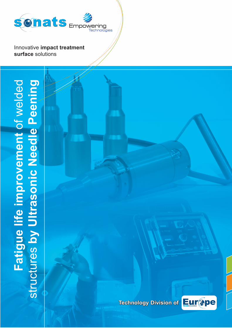
Technology Division of Innovative impact treatment surface solutions Fatigue life improvement of welded structures by Ultrasonic Needle Peening
Transcript of of welded by Ultrasonic Needle Peening Fatigue life … · Fatigue life improvement of welded...
Technology Division of
Innovative impact treatment surface solutions
Fatig
ue li
fe im
prov
emen
t of w
elde
d st
ruct
ures
by
Ultr
ason
ic N
eedl
e Pe
enin
g

Technology Division of Europe TechnologiesSONATS_WP/UNP_Rev0
Table of Content
1. Abstract .................................................................................................................................. 4
2. UNP Effects ............................................................................................................................ 42.1. Modificationoftheweldtoegeometry ............................................................................. 52.2. Compressiveresidualstresses........................................................................................ 6
3. Process parameters ............................................................................................................... 63.1. MechanicalVibrationfrequencyandNeedleImpactfrequency ...................................... 63.2. Amplitudeofvibration ...................................................................................................... 83.3. UltrasonicNeedlePeeningPower ................................................................................... 93.4. Geometryanddiametersofimpactors/needles ............................................................... 9
4. Fatigue Recommendations ................................................................................................. 104.1. IIWrecommendations.................................................................................................... 104.2. Classificationsocietiesapproaches............................................................................... 10
4.2.1. AmericanBureauofShipping–ABS ................................................................ 104.2.2. Lloyd’sRegister–LR ..........................................................................................114.2.3. BureauVERITAS ...............................................................................................11
4.3. AmericanAssociationofStateHighwayandTransportationOfficials(AASHTO) andFederalHighwayAdministration(FHWA)Recommendations .................................11
5. Results with SONATS UNP equipment .............................................................................. 125.1. Publishedstudies ......................................................................................................... 12
5.1.1. FatigueLifeEnhancementofWeldedStructuresusingSTRESSONIC® UltrasonicNeedlePeening16 .......................................................................... 125.1.2. FatiguebehavioronHFhammerpeenedlongitudinalattachments ............... 135.1.3. FatiguelifeimprovementofweldedstructuresbyUltrasonicNeedle PeeningcomparedtoTIGdressing ................................................................ 145.1.4. US Navy: Systematic review of the UIT parameters on residual stresses ofsensitizedAA5456 and field based residual stress measurements for predicting andmitigatingstresscorrosioncracking ............................................................................ 15
5.2. StudiesinProgress ....................................................................................................... 155.2.1. SociétéNationaledesCheminsdeFer-SNCF-France ................................. 155.2.2. Mechanismsunderstandingofhammerpeeningeffectinweldedstructureunderfatigueloading ............................................................................................................... 165.2.3. FATIGUE BEHAVIOUR OF ARC WELDED ASSEMBLIES: PATHS OFIMPROVEMENT .......................................................................................................... 16

Technology Division of Europe TechnologiesSONATS_WP/UNP_Rev0
6. SONATS Experience ............................................................................................................ 166.1. Civilengineeringstructures ........................................................................................... 166.2. Heavymachinery ........................................................................................................... 176.3. Shipbuilding ................................................................................................................... 176.4. Energy ........................................................................................................................... 176.5. Defense ......................................................................................................................... 186.6. Automatedpeeningsolutions ........................................................................................ 18
7. References ............................................................................................................................ 19
Révision Modifications Date Writer0 Issue 2014,December8th P.LEFEVRE

Technology Division of Europe TechnologiesSONATS_WP/UNP_Rev0
1. AbstrAct
Conventional Hammer Peening is a well-known post-weld treatment for fatigue lifeimprovement. This method is applied to theweldtoeonly.UltrasonicNeedlePeening(UNP)(alsocalledUltrasonic Impact Treatment (UIT) or HighFrequency Mechanical Impact (HFMI)) is aprocess achieving the same effect, but withmuchprocesscontrolcomparedtoconventionalneedle peening. UNP is also faster and farless harmful for the operator.Moreover UNPprocesscanbeusedbyanyoperatorafteronlyone day of training. For these reasonsmanyindustrieshaveshownastronginterestforthisinnovativetechnology.
This document describes SONATS research,in-field experiences and knowledge aboutUltrasonicNeedle Peening. It is dedicated toany people (Engineers, welders, operators,controllers)whoareinterestedinthisprocess.
NOTE: Many designations are used to describe the process which consists in using high frequency mechanical vibrations to put in movement impactors or needles to throw against the metal surface area to be treated:
- UIT for Ultrasonic Impact Treatment, - UNP for Ultrasonic Needle Peening, - UP for Ultrasonic Peening, - or HFMI for High Frequency Mechanical Impact
treatment).
In this document we will, most of time, use “Ultrasonic Needle Peening” or “UNP”.
Figure 1 : SONATS StressVoyager® UNP System
2. UNP EffEcts
AccordingtoP.J.HaagensenandS.J.Maddox1,“Theweldtoeisaprimarysourceoffatiguecrackingbecauseof theseverityof thestressconcentration itproduces”.For this reason, theweld toe can be considered as a“notch”.
Hammer Peening or Needle Peening is anancestral process,which consisted in strikingmanuallyaweldby themeansofahammer,to improve its surface finish and resistance.Later, pneumatic and magnetostrictive toolshave been developed to help the operator.Nowadays, the principle is still the same butthe equipment design has been improved.The latest technologiesareusingpiezoeffectfor electrical to mechanical vibration. Thevibrating element, named Sonotrode, is thenuse toprovide thekineticenergy toaneedle(or impactor). Thanks to thosemodern tools,the influence of the operator on the processapplication is close to zero, with little effortsandhightreatmentspeed.
ResearchaboutUNPstartedinthelatefifties2 and sixties in the USSR 3 4 5 . Extensiveresearch have been carried out later in thenineties, on structural steels 6, high strengthsteel and aluminum 7 8, showing each time ahighlevelofimprovementintermoffatiguelife.In1996, the International InstituteofWeldingpublishedaspecification9andin1999thefirst“GuideforapplicationofUIT”10.

Technology Division of Europe TechnologiesSONATS_WP/UNP_Rev0
On thisbasis,many industries started topayattentiontothiseffectiveanduser-friendlypost-weldimprovementtechniques.
Theweldtoeimprovementmethodsrelyontwomainprinciples:
• Weldtoegeometrymodification,• ResidualStressesModification.
Ultrasonic Needle Peening acts on bothphenomenon to finally achieve high levelfatiguelifeimprovementofthetreatedweldeddetail.
2.1. Modification of the weld toe geometry
Conventionalmethodsofpostweldtreatments,such as TIG dressing or weld toe grindingconsistofincreasingtheradiusatthetransitionbetweenthebasematerialandtheweldseam.UNPachievedthesameeffectbythemeanofhigh frequency impacts, able to induce localdeformation,andcreatingacontrolledgrooveattheweldtoe.
The following picture presents the geometrymodification after UNP/UIT compared to “aswelded”orotherposttreatmentmethods.
Figure 2: Image illustrating weld to geometries for “as welded” condition and after post treatment
(burr grinding UIT and TIG dressing)11
The treatmentshouldbeapplieduniformlyallalongtheweldtoewithoutanydiscontinuities.Thegroovecreatedbysuccessiveimpactscanberepresentedasfollowing.
largeur
rayon
profondeur
Métal de base
Métal d’apport
Figure 3: UNP groove scheme
Results observed in the literature, present awide range of groove sizes. Galtier and al12
measured after UIT on 2 steel grades, radiifrom0.8mmto2.0mmanddepthfrom0.17mmto0.4mm.Yildirim & Marquis 13 studied the effect ofseveral HFMI tools, the radii weremeasuredfrom1.80mm to 4.55mm,Width from2.39 to5.45mmandDepthfrom0.16mmto0.29mm.
Another study carried out by Yekta and Al14 shows the following groove sizes for oneequipment with several different peeningtreatmenttimes.
Figure 4 : Radius (from 1.17 to 2.37 mm) and Depth (from 0.16 to 0.36mm) according to several peening
conditions 14
All geometries presented in these 3 studiesleadtoahighlevelofimprovementintermsoffatiguelife,byusingdifferentUNPequipment,treatmentprocedureandonseveralmaterials.

Technology Division of Europe TechnologiesSONATS_WP/UNP_Rev0
In 2013, Marquis and Barsoum15 compiled46 studies from the last decade to createprocedures and quality assurance guidelinesabouttheUNPprocess.Inthisdocument,wecanread“TheHFMIindentationdepthfollowingtreatment should be 0.2–0.6 mm while theresultingwidthistypically2–5mm”.
NOTE: These values are given as typical geometries; it results from a complete coverage of the weld toes by impacts (also called 100% coverage).
2.2. Compressive residual stresses
ThesecondeffectofUltrasonicNeedlePeeningis the introduction of beneficial compressiveresidual stresses. Depending on the tool,intensityofthetreatmentandmaterial,thelevelofintroducedcompressioncanvary.
The following graph presents residual stressprofiles obtain after treatment by UNPequipmentonS355;severalsetupconditionshavebeencharacterized.Thesemeasurementshave been performed by XRay diffraction atSONATSLaboratory(Carquefou,France).
Direction transversale
Con
train
tes
rési
duel
les
(MPa
)
non martelé
Figure 5: Residual stress distribution (transversal direction) at the surface and into depth, weld toe
location
The red curve corresponds to “As welded”specimen, high tensile residual stresses isobserveddownto1.6mm.After UNP, we observe high compressiveresidualstressesdowntomorethan1.4mmforallconditions.Asforshotpeening(orUltrasonicShot Peening), compression introduced isbeneficialforthefatiguelife,actingagainsttheservice loads.
Yildirim & Marquis 13 observe similar results,“tensile residualwere foundatallof theweldtoes measured. Values ranged from +185 to+552MPa. For theHFMI-treated specimens,compressiveresidualstressesweremeasuredin31of the32HFMIgroovesstudiedprior tofatiguetesting.ThesingleHFMIgroovewhichshowedtensile residualstresshadavalueofonly52MPa.Thecompressiveresidualstressesbefore fatigue testingwere−53 to−457MPaforthehigh-strengthsteelspecimens.”
Following this investigation, authors concludethatUNPimpartscompressivestressesinweldtoesbeingtreatedforallthetestedequipment’s.
3. ProcEss PArAmEtErs
The UNP/UIT/HFMI process is monitoredby several parameters, influence of theseparametersarediscussedinthisparagraph.
3.1. Mechanical Vibration frequency and Needle Impact frequency
OnanUltrasonicPeeningsystem,ahighvoltageelectrical signal is created by an UltrasonicGenerator.This signal is then converted to amechanical vibration at the same frequency,either by a piezo-electrical converter or amagnetostrictiveconverter.When the Needle (or Impactor) is in contactwiththevibrationsurface,itgainskineticenergyand is thrown against the part to be treated.Then theneedlemovesback to the vibratingsurfaceforthenextcycle.Therefore theMechanicalVibration frequencyand the Needle Impact frequency should bedissociated.
Technology Division of Europe TechnologiesSONATS_WP/UNP_Rev0
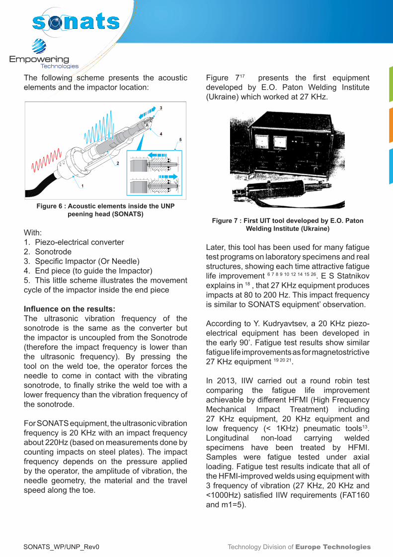
The following scheme presents the acousticelementsandtheimpactorlocation:
Figure 6 : Acoustic elements inside the UNP peening head (SONATS)
With:1. Piezo-electricalconverter2. Sonotrode3. SpecificImpactor(OrNeedle)4. Endpiece(toguidetheImpactor)5. Thislittleschemeillustratesthemovementcycleoftheimpactorinsidetheendpiece
Influence on the results:The ultrasonic vibration frequency of thesonotrode is the same as the converter buttheimpactorisuncoupledfromtheSonotrode(therefore the impact frequency is lower thanthe ultrasonic frequency). By pressing thetool on theweld toe, the operator forces theneedle to come in contact with the vibratingsonotrode,tofinallystriketheweldtoewithalowerfrequencythanthevibrationfrequencyofthesonotrode.
ForSONATSequipment,theultrasonicvibrationfrequencyis20KHzwithanimpactfrequencyabout220Hz(basedonmeasurementsdonebycounting impactsonsteelplates).The impactfrequency depends on the pressure appliedbytheoperator,theamplitudeofvibration,theneedle geometry, the material and the travelspeedalongthetoe.
Figure 717 presents the first equipmentdeveloped by E.O. Paton Welding Institute(Ukraine)whichworkedat27KHz.
Figure 7 : First UIT tool developed by E.O. Paton Welding Institute (Ukraine)
Later,thistoolhasbeenusedformanyfatiguetestprogramsonlaboratoryspecimensandrealstructures,showingeachtimeattractivefatiguelifeimprovement6 7 8 9 10 12 14 15 26.ESStatnikovexplainsin18,that27KHzequipmentproducesimpactsat80to200Hz.ThisimpactfrequencyissimilartoSONATSequipment’observation.
AccordingtoY.Kudryavtsev,a20KHzpiezo-electrical equipment has been developed intheearly90’.Fatiguetestresultsshowsimilarfatiguelifeimprovementsasformagnetostrictive27KHzequipment19 20 21.
In 2013, IIW carried out a round robin testcomparing the fatigue life improvementachievablebydifferentHFMI(HighFrequencyMechanical Impact Treatment) including27 KHz equipment, 20 KHz equipment andlow frequency (< 1KHz) pneumatic tools13. Longitudinal non-load carrying weldedspecimens have been treated by HFMI.Samples were fatigue tested under axialloading.FatiguetestresultsindicatethatalloftheHFMI-improvedweldsusingequipmentwith3frequencyofvibration(27KHz,20KHzand<1000Hz)satisfiedIIWrequirements(FAT160andm1=5).

Technology Division of Europe TechnologiesSONATS_WP/UNP_Rev0
This round robin test and previous studies clearly show that the vibration frequency has no influence on the fatigue life improvement generated by UNP/UIT process. Important parameter is the frequency of impact, and its reproducibility.
A smooth and complete continuity of grooveshould be produced by operator on theweldtoes.Thanks to itsconsistentpeening impactfrequencyandamplitude,SONATSequipmentallowsamuchquickerprocesswithoutharmfulconditions for the operator. Low frequencypneumatic tools suffer from a lack of controlon impact frequency and amplitude, andinduceharmfulpeeningconditionswhichmakedifficultforanoperatortoachieveabrightandcontinuousgroove.
3.2. Amplitude of vibration
Avibration isdefinedby its frequencyand itsamplitude. Usually, when the frequency ofvibration increases, theamplitudedecreases.SONATS StressVoyager® UNP equipment isabletoworkintherangeof10µmp/pto60µmp/p.
The Figure 8 below presents the sinusoidalultrasonic wave.
Figure 8 : Sinusoidal wave
Thehigh levelofenergyto treat theweld toeis obtained thanks to small displacement atreallyhighspeed,inducingahighaccelerationoftheimpactor.Smallamplitudeisuserfriendlycompared to high amplitude obtained at lowfrequency by pneumatic equipment (severalmillimetersofdisplacement).
The amplitude of vibration should be easilymodified depending on the material to treat.To achieve IIW requirements (groove size),SONATSusuallyusesthefollowingamplitudeofvibration:
Table 1 : Typical sonotrode’s amplitude of vibration for SONATS StressVoyager® UNP equipment
SONATSperformedfatiguetestwith60µmp/pamplitude achieving high level of fatigue lifeimprovement16.AndréGlatierandAl12, used an amplitude of vibration of the sonotrode equalto40µmp/ptotreatHighStrengthSteel,thefatiguelifeoftheT-Jointspecimenismorethantwicethan“as-welded”.
Theamplitudeofvibrationisnotconsideredasakeyparameterinalargemajorityofpublications.Thus the influence of this parameter on thefatiguelifeimprovementhasnotbeenstudied.Eveniftheinfluenceoftheamplitudeissmallwithrespecttothefatiguelifeimprovement,ithas a real influence on the treatment speedandequipmentdrivability,andthereforeonthegroovecontinuityandquality.Forthisreason,aperfectcontrolofthevibrationamplitudeofthesonotrodeisreallyimportant.
Technology Division of Europe TechnologiesSONATS_WP/UNP_Rev0
3.3. Ultrasonic Needle Peening Power
Somestudiestalkaboutthepowerconsumptionoftheultrasonicequipment.It’saconsequenceofseveralparameterswhichare:• Convertertechnology(Piezoelectricor
Magnetostrictive)• DesignandManufacturingqualityofthe
equipment• Pressureappliedbytheoperatoronthetool• Materialtobetreated• Amplitudeofvibration
Dependingon theseparameters theeffectiveequipment power consumption can bemultipliedby10toachieveidenticalfatiguelifeimprovement.
SONATSequipmentpowerconsumptionrangesfrom10watts(withoutloads)to150watts(duringthe treatment), this low energy consumptioncomes from piezo electrical converter whichisveryefficientcompared tomagnetostrictivetransducer. For magnetostrictive transducers,amajorityofelectricalpowerisconvertedintoheat,thatiswhywatercoolingisnecessary.
For piezo electrical converters which aremore efficient, the electrical power is mainlyconverted into mechanical vibration which isthentransmittedtotheweldtoe.Aircoolingissufficient.
Thepowerconsumptionoftheequipmentisaconsequenceoftheparameterlistedbefore;ithasnoparticularsignificationonthequalityoftheUNPtreatment.
3.4. Geometry and diameters of impactors/needles
Impactors also called needles or strikers areusuallymadeofhardsteel.
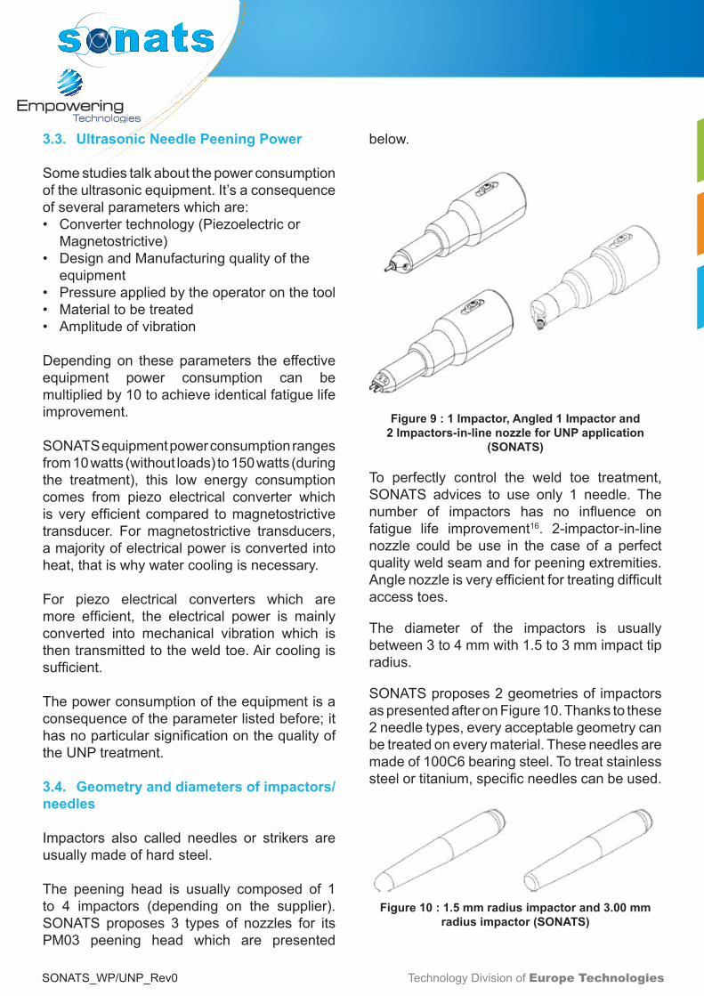
The peening head is usually composed of 1to 4 impactors (depending on the supplier).SONATS proposes 3 types of nozzles for itsPM03 peening head which are presented
below.
Figure 9 : 1 Impactor, Angled 1 Impactor and 2 Impactors-in-line nozzle for UNP application
(SONATS)
To perfectly control the weld toe treatment,SONATS advices to use only 1 needle. Thenumber of impactors has no influence onfatigue life improvement16. 2-impactor-in-linenozzle could be use in the case of a perfectqualityweldseamandforpeeningextremities.Anglenozzleisveryefficientfortreatingdifficultaccess toes.
The diameter of the impactors is usuallybetween3to4mmwith1.5to3mmimpacttipradius.
SONATSproposes2geometriesofimpactorsaspresentedafteronFigure10.Thankstothese2needletypes,everyacceptablegeometrycanbetreatedoneverymaterial.Theseneedlesaremadeof100C6bearingsteel.Totreatstainlesssteelortitanium,specificneedlescanbeused.
Figure 10 : 1.5 mm radius impactor and 3.00 mm radius impactor (SONATS)
Technology Division of Europe TechnologiesSONATS_WP/UNP_Rev0
4. fAtigUE rEcommENdAtioNs
These paragraphs detail the UNP processrecommendations according to InternationalInstitute of Welding (IIW), classificationsocieties, and professional associations ontransportationinfrastructures.
4.1. IIW recommendations
WithrespecttoPostWeldTreatmentMethods, the following document isconsideredasreferenceworldwide:
“IIWRecommendationsonPostWeldFatigueLife Improvement of Steel and AluminiumStructures”22
This document has been created in order tostandardize theoptimumapplicationmethodsforburrgrinding,TIGdressing,hammerpeeningandneedlepeening.Itisalsoincludingdesignresistancecurvesbasedonbothnominalstressassessmentmethodandonthestructuralhot-spotstressmethod.ThisIIWguidelinedoesnottake into account Ultrasonic Needle Peeningmethodyet.However,in2013IIWpublishedasetof2complementarydocumentscalled:
• Fatiguestrengthimprovementofsteelstructuresbyhigh-frequencymechanicalimpact:proposedproceduresandqualityassuranceguidelines15.
• Fatiguestrengthimprovementofsteelstructuresbyhigh-frequencymechanicalimpact:proposedfatigueassessmentguidelines 23
SONATSstronglyadvisesanyoneinterestedinUNPprocess,toreadthese2documents.
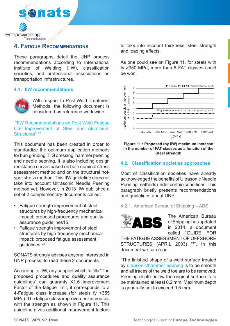
AccordingtoIIW,anysupplierwhichfulfills“Theproposed procedures and quality assuranceguidelines” can guaranty X1.6 ImprovementFactorof the fatigue limit, itcorresponds toa4-Fatigue class increase (for steels fy <355MPa).Thefatigueclassimprovementincreaseswith thestrengthasshown inFigure11.Thisguidelinegivesadditionalimprovementfactors
to take into account thickness, steel strengthandloadingeffects.
AsonecouldseeonFigure11,forsteelswithfy>950MPa,morethan8FATclassescouldbewon.
Figure 11 : Proposed (by IIW) maximum increase in the number of FAT classes as a function of the
Steel strength
4.2. Classification societies approaches
Most of classification societies have alreadyacknowledgedthebenefitsofUltrasonicNeedlePeeningmethodsundercertainconditions.Thisparagraph briefly presents recommendationsandguidelinesaboutUNP.
4.2.1. AmericanBureauofShipping–ABS
The American BureauofShippinghasupdatedin 2014, a documentcalled “GUIDE FOR
THEFATIGUEASSESSMENTOFOFFSHORESTRUCTURES (APRIL 2003) 24”. In thisdocumentwecanread:
“Thefinishedshapeofaweldsurfacetreatedbyultrasonic/hammerpeeningistobesmoothandalltracesoftheweldtoearetoberemoved.Peeningdepthbelowtheoriginalsurfaceistobemaintainedatleast0.2mm.Maximumdepthisgenerallynottoexceed0.5mm.

Technology Division of Europe TechnologiesSONATS_WP/UNP_Rev0
Providedtheserecommendationsarefollowed,whenusingtheABSS-Ncurves,a credit of 2 on fatigue lifemaybepermittedwhensuitabletoe grinding or ultrasonic/hammer peeningare provided. Credit for an alternative lifeenhancementmeasuremaybegrantedbasedon the submission of a well-documented,project-specificinvestigationthatsubstantiatestheclaimedbenefitofthetechniquetobeused.”
4.2.2. Lloyd’sRegister–LR
The following table presents the post-weldmethods (including UNP) improvement factoraccordingtoLloyd’sregisters.
Table 2 : Improvement factor of fatigue life for several post-weld improvement methods (including
UIT) according to Lloyd’s Register
4.2.3. BureauVERITAS
The following recommendation ispresentedinBVdocument“RulesfortheClassificationofOffshoreUnits“26
Figure 12 : Accepted Post welding treatment by Bureau VERITAS
Figure 13: Fatigue assessment procedure
4.3. American Association of State Highway and Transportation Officials (AASHTO) and Federal Highway Administration (FHWA) Recommendations
In United States of America, as in Europeor in Japan, some existing welded bridgesare prone to fatigue failure. The US FederalHighwayAdministration(FHWA)estimatesthat$76 billion are necessary to repair deficientbridges across the United States. For thisreason, in 1996 the FHWA decided to studythe “Post-Weld treatment of a welded bridgegirderbyUltrasonicImpactTreatment”26 ,thisprocesshasbeen judgedasverycompetitivecomparedtoconventionalmethods,toextendthe fatigue life and reduces themaintenancecosts of existing welded bridges. Later,Pr.RoyandPr.Wright fromLehighUniversity,experimentally investigated the fatigue
Technology Division of Europe TechnologiesSONATS_WP/UNP_Rev0
performancebridgegirderswithweldedgirdersand cover plates.Medium strength steel andhigh strength steel have been tested withseveral combinations of cover platesweldingconfigurations. The conclusion of this studywas fora largemajorityofspecimens, failurelocatedattheweldtoeofthecoverplates,with1to4categorydetailimprovementaccordingtoAASHTO.This recommendation is presentedinthefollowingdocument:
“AASHTO LRFD Bridge Construction Specifications - Second Edition 2004 (2008 Interim Revisions)”
5. rEsUlts with soNAts UNP EqUiPmENt
5.1. Published studies
SONATShasa20years’experienceinresearchfor impact surface treatment activated byultrasounds.Mostoftheseresearchprogramshave been conducted under confidentialagreementswithend-customers.
This paragraph presents some publishedpapers with respect to SONATS UltrasonicNeedlePeeningequipment.
5.1.1. Fatigue Life Enhancement of WeldedStructures using STRESSONIC® UltrasonicNeedlePeening16
TheFrenchInstituteofWelding,incollaborationwith SONATS, conducted a study aimed toevaluate Ultrasonic Needle Peening processcapability to increase the fatigue life ofweldedcomponents.Theresultsof thisstudyhave been presented at ICSP11 Conference(Indiana,USA-2011).
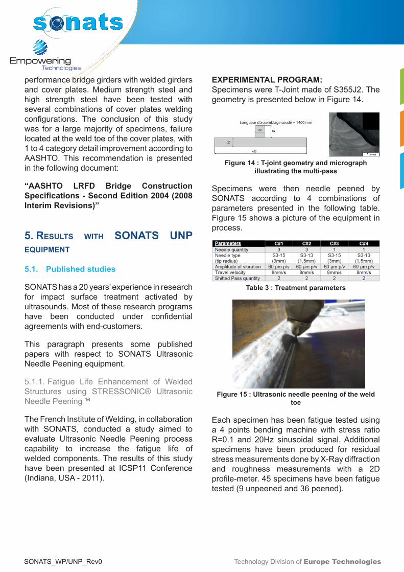
EXPERIMENTAL PROGRAM:SpecimenswereT-JointmadeofS355J2.ThegeometryispresentedbelowinFigure14.
Longueur d’assemblage soudé = 1400 mm
Figure 14 : T-joint geometry and micrograph illustrating the multi-pass
Specimens were then needle peened bySONATS according to 4 combinations ofparameters presented in the following table.Figure15showsapictureoftheequipmentinprocess.
Table 3 : Treatment parameters
Figure 15 : Ultrasonic needle peening of the weld toe
Eachspecimenhasbeenfatiguetestedusinga 4 points bendingmachinewith stress ratioR=0.1 and 20Hz sinusoidal signal.Additionalspecimens have been produced for residualstressmeasurementsdonebyX-Raydiffractionand roughness measurements with a 2Dprofile-meter.45specimenshavebeenfatiguetested(9unpeenedand36peened).

Technology Division of Europe TechnologiesSONATS_WP/UNP_Rev0
RESULTS:As expected, the Ultrasonic Needle peeningtreatmenthascreatedaplasticdeformationoftheweldtoesbygeneratingagroovealongtheweldtoe.ForeachcombinationofparametersresidualcompressivestressesareobservedasshowninFigure16.
Figure 16 : Residual stress profiles in the longitudinal and transversal direction for as welded
and UNP specimens
For each combination of parameters, fatiguelife improvement isobservedcompared toasweldedresultsasshowninFigure17.
Figure 17 : Fatigue test results for as welded, UNP treated specimens and IIW publication 28
Figure 18 : Stress range at 2e6 cycles
The resultsshowan improvementup to50%in stress range at 2 million cycles. Fatiguelifewasincreasedat leastbyaratioof3andup to 5 for 350Mpa stress range. The UITcondition, set 2 from study XIII-1817-00, hasbeen used for comparison and validation ofcurrentwork.Betweenbothstudiesresultsarefound comparable.Whatever parameter sets,we still observed a significant enhancementfor all specimens.This demonstrates the lowinfluenceofvariedparameterssuchasneedleradiusandneedlequantity.
5.1.2. FatiguebehavioronHFhammerpeenedlongitudinalattachments29
The objective of this study is to evaluatethe fatigue strength of UNP on longitudinalattachment welded joints in bending with astressratioR=0.1.
Figure 19 : Specimen geometry and treated weld toe
Siximprovedspecimensweretestedataloadlevelfixedandoneas-welded.Theresultswerecomparedwithprecedentstudiesonthesamespecimenswithdifferentweldimprovements.

Technology Division of Europe TechnologiesSONATS_WP/UNP_Rev0
Figure 20 : Fatigue life time observed on longitudinal attachment for different Post-weld
treatment including UNP (by SONTAS)
As illustrated on Figure 20, if one comparesHF Hammer peening (SONATS) results with“as-welded” results, we observe a meanlife time equal 740.000 cycles for UNP and320.000 cycles for “aswelded” specimens. Itcorresponds toa2.3 fatigue life improvementfactor.
5.1.3. Fatigue life improvement of weldedstructures by Ultrasonic Needle PeeningcomparedtoTIGdressing30
Twoimprovementtechniqueswerestudied:• TIGdressing• UltrasonicNeedlePeening
These post weld treatments are intended innewstructurestoincreasethefatiguestrengthandalsoforpostrepairoperationsorupgradingofexistingshipbuildingstructures.
EXPERIMENTAL PROCEDURES:Thematerial considered in thiswork is a hotrolledS355NL,gradewidelyused insurfaceshipbuildingbyDCNS.The plate’s dimensions are 3000mm length,700mmwidthand12mmthickness.Figure21presentsthegeometryofthespecimenbeforemachining.
Figure 21: Non-load carrying attachment welded on 12 mm thickness plate
The weld is then treated by SONATS (seeFigure 22) before machining of the fatiguespecimens.
Figure 22 : Ultrasonic Needle Peening equipment and operation by SONATS
Specimens after machining are rectangularplates(400mmlengthand80mmwidth)
Fatigue tests were conducted, on TIG andUNP treated specimens, under axial loadingon electrohydraulic machines at 5-10Hz infunctionofthemaximalstressapplied.

Technology Division of Europe TechnologiesSONATS_WP/UNP_Rev0
RESULTS:Residual stressmeasurementwasperformedintheUNPtreatedarea(SeeFigure23)
Figure 23 : Residual stress measurement by XRay diffraction
Residual compressive stresses are observedindepthupto1.7mmaftertreatmentbyUNP.
Figure24summarizestheΔσ-Ncurvesat2sdtvforthetwopost-weldtreatmentsandas-weldedspecimens. Results are obtained in traction-compression R=-1. The red line correspondstothedesigncurveFAT100MPaaccordingtoIIWrecommendation
Figure 24 : Δσ-N curves for as welded, TIG dressed and UNP treated specimens
Highlevelofimprovementisobservedforbothmethods,betterresultsareobtainedbyUNP.As presented by the authors, the calculatedFATforasweldedspecimenis137MPa,254MPaforTIGDressingand357MPaforUNP.
5.1.4. USNavy:Systematicreviewof theUITparameterson residualstressesofsensitizedAA5456 and field based residual stressmeasurements for predicting and mitigatingstresscorrosioncracking31
This thesis focuses on the use of x-raydiffractiontomeasureresidualstressesaroundwelds inaluminumshipstructuresboth in thelaboratory and in the field. Tensile residualstresses are often generated during weldingand, in sensitized aluminum structures, cancause extensive stress corrosion cracking.Peeningtechniques,suchasultrasonicimpacttreatment (UIT by SONATS), can mitigateand even reverse these tensile residualstresses. This research uses x-ray diffractiontomeasureresidualstressesaroundwelds inAA5456beforeandafterUIT.Inparticular,weexamined the importance of UIT parameterssuchaspeeningamplitudeandpinsize.AuthorfoundthatallcombinationsofUITparametersremoved the tensile residual stresses andresultedincompressivestressseveralhundredmicronsbelowtheweldsurface.Theexactlevelofcompressiveresidualstresswassensitivetothepinsizeusedwithasmaller,butmeasurable,dependenceuponthedisplacementamplitude. 5.2. Studies in Progress
5.2.1. SociétéNationaledesCheminsdeFer-SNCF-France
As presented in the IIW Document” XIII-2545-14”32 ,SNCF is leadingastudy. Itaimsto establish the fatigue criteria for ultrasonicneedle peened fillet welds under frequentlyobserved service loads. Specimens made offine-grainedsteelare testedusing twostressratios.Theprogramwillbeendedbyperformingfatiguetestsonrealsizecomponents.

Technology Division of Europe TechnologiesSONATS_WP/UNP_Rev0
5.2.2. Mechanisms understanding of hammerpeeningeffectinweldedstructureunderfatigueloading
IncollaborationwithCETIM(CentreTechniquedesIndustriesMécaniques),anexpertresearchcenter, and other companies, SONATS isinvolved in a research program aimed tounderstandtheUNPeffectinweldedstructures.
Ifalltheresults,mainlyfromtheliteraturesurvey,suggest that conventional or HFMI peeningcouldbetheoptimalsolutionforimprovingthefatiguestrength,forthecrackedorfatiguejointrepair,somequestionsstillarise:• WhatistheHFMIpeeningefficiencyforthe
differentdomainsoffatigue(lowcycles,limitedenduranceorhighcycles)?
• Whataretheinfluencingparameters(residualstress,geometryoftheweldtoe,hardening...)?
• Whataretheinvolvedmechanisms?
Insummary,theon-goingstudyis:“Why,howand under which conditions of solicitations,HFMIpeeningiseffectiveinweldedstructure?“.
5.2.3. FATIGUE BEHAVIOUR OF ARCWELDED ASSEMBLIES: PATHS OFIMPROVEMENT33
InordertotakeadvantageofUltraHighStrengthSteels (AHSS) in the automotive industry,ARCELORMITALwouldliketoproposeto itscustomersanefficientandrobotizedpostweldtreatmentmethod.Thethicknessofthetestedsamples is 2 mm (as currently observed inautomotiveindustry).
Inafirststep,severalpost-weldimprovementmethodshavebeen tested,TIGdressingandUNP by SONATS have been selected dueto the interesting fatigue life improvementobservedaftertreatmentwiththesetechniques.Additionaltestsareongoinginordertoconfirmpreviousresults.
6. soNAts ExPEriENcE
SONATS was founded in 1991 and hasmore than20yearsofexperience in residualstress measurements and surface impactstreatmentsactivatedbyultrasound for fatiguelife improvements. This paragraph presentssomechosenexamplesofourexperienceonUNPfeaturedprojects(Pleaseconsultusifyouwanttoknowmoreabout).
6.1. Civil engineering structures
StressVoyager®UNPoffersaportablesolutioneasy to use and has been accepted by thePortAuthority of NewYork to extend the lifeof the George Washington Bridge’s upperlevel structural steel deck (2014). ExtensiveUNP operations have been conducted bythe contractor American Bridge during aboutone year (See American Bridge Journal -AB Connections, Summer 2012 on www.americanbridge.net).
Figure 25 : George Washington Bridge
Beside this remarkable example,StressVoyager®UNPhasbeenusedonbridgerepairs, or new bridges, in USA, Canada,Europe and Asia. SONATS / ETI providesStressVoyager®UNPequipmentleasingafterdedicatedtrainingforbridgework.

Technology Division of Europe TechnologiesSONATS_WP/UNP_Rev0
6.2. Heavy machinery
Manufacturers of heavy haulage constructionequipmentengagedSONATS/ETIforasolutionto ensure optimum weld Quality Assurancewasmaintainedoncriticalstructuresandweldjoints,withverypositiveresults.
Figure 26 : Example of Wheel loader part
UNPwasaddedbyourend-customersintotheirspecificationsasamethodof fatiguestrengthandlifeenhancement.
6.3. Shipbuilding
Manufacturers engaged SONATS/ ETI toultrasonically needle peen the critical weldedareaonseveralNordicseastankersrudderstoimprovefatiguestrengthandfatiguelife.
Figure 27 : Nordic Sea Tanker Rudder repair
SONATS provided UNP service onsite topreventcrackingfromfatigueandtensilestress.Treatmenthasbeenveryefficientassincenomorecrackshavebeenobserved.
Besidethisrepairprojectexample,SONATSandits US Subsidiary Empowering Technologies,havebeenengagedtotreatneworusedshipstructures(bothforSteelorAluminum).

Technology Division of Europe TechnologiesSONATS_WP/UNP_Rev0
6.4. Energy
SONATSEngineeringServicesteamwascalledin by customer study department to evaluatethefeasibilitytoimpartbeneficialcompressivestresses on critical welded areas.
Objectivewas to increase themaximum loadresistanceonadefineddesignofWindturbineto adapt to a different applicative condition.SONATS deployed Engineers and UNPoperators to collaborate with Wind EnergyCompanyand to treatweldconnectionsonanacellewithhardaccessibleworkenvironments(seeFigure28).
Figure 28 : Wind turbine nacelle
TheWindturbinenacelleworkstooktwoweekswithtwocrewstocomplete.
6.5. Defense
SONATS developed a unique device ableto needle peened very largewelded area onaluminumframesofamphibiousmotorvehicles.It results to a high surface finish quality andimproveresistancetocorrosion.
Figure 29 : Aluminium frame of an amphibious military heavy equipme
6.6. Automated peening solutions
SONATS/ETIisdevelopingaroboticdeviceinordertoapplyUNPtechnologyinanautomated,controlled,repeatableprocess(seeFigure30).
Figure 30 : Robotic UNP on automotive chassis
Technology Division of Europe TechnologiesSONATS_WP/UNP_Rev0
7. rEfErENcEs
1P.J.HaagensenandS.J.Maddox,IIWRecommendationson Post Weld Fatigue Life Improvement of Steel andAluminiumStructuresXIII-2200r7-07,2007
2A. V. Mordvintseva “Ultrasonic treatment of weldedjoints” - “Ultrasound application inwelding”МMoscow,CLTINIIEofElectricalIndustry,1959,pages32-43.
3I.I. Mukhanov, Yu. M. Golubev, V.N. Philimonenko“Ultrasonic strengthening of machine steel parts”-ProceedingsoftheNovosibirskScienceandTechnologyConference on Machine Building, ch. 1. Novosibirsk:NTOMashprom,1964,p.27-39.
4Langenecker,EffectofSonicandUltrasonicRadiationof Safety Factors of Rockets and Missiles, “JournalAIAA”,№1,1963.
5E. Konovalov, V. Drozdov, M. Tyavlovsky “Dynamicstrength of metals”, “Science and Engineering”PublishingHouse,Minsk1963,300pages.
6V.I. Trufiakov, E.S. Statnikov, P.P. Mikheev and A.Z.KuzmenkoTheEfficiencyofUltrasonicImpactTreatmentfor Improving the Fatigue Strength of Welded Joints,1998,IIWDocumentXIII-1745-98
7P. J. Haagensen1, E.S. Statnikov2 and L. Lopez-Martinez3-Introductoryfatiguetestsonweldedjointsinhighstrengthsteelandaluminiumimprovedbyvariousmethods including Ultrasonic Impact Treatment (UIT),1998,IIWDoc.XIII-1748-98.
8P.Castellucci ,V.I.Troufiakov, P.P. Mikheev ,E.CH.Statnikov–Lemartelageparultras-sonsdessouduresenacierHLE–Soudageet techniquesconnexesMai/Juin1991
9E.CH.Statnikov,V.I.Trufiakov,P.P.MikheevandYu.F.Kudryavtsev.Specificationforweldtoeimprovementbyultrasonic impact treatment. IIWDoc.XIII–1617-96.(1996)
10E.S.Statnikov.GuideforapplicationofUITimprovingfatiguelifeofweldedstructures.IIW/IISDoc.XIII–1757–99(1999).
11M.M. Pedersen, O.Ø. Mouritsen, M.R. Hansen, J.G.Andersen, J. Wenderb. Comparison of Post WeldTreatment of High Strength Steel Welded Joints inMediumCycleFatigueXIII-2272-09,2009
12André Galtier, Efim Statnikov , The Influence of
13Ultrasonic Impact Treatment on Fatigue Behavior ofWeldedJointsinHigh-StrengthSteel,IIW/IISDocumentXIII-1976–03,2003
14HalidCanYildirim&GaryB.Marquis,A round robinstudy of high-frequency mechanical impact (HFMI)-treated welded joints subjected to variable amplitudeloading,WeldWorld(2013)57:437–447
15Rana Tehrani Yekta, Kasra Ghahremani, ScottWalbridge,Effectofqualitycontrolparametervariationsonthefatigueperformanceofultrasonicimpacttreatedwelds–InternationaljournalOffatigue-2013
16Gary Marquis & Zuheir Barsoum, Fatigue strengthimprovement of steel structures by high-frequencymechanical impact: proposed procedures and qualityassuranceguidelines,WeldWorldDOI10.1007/s40194-013-0077-8,2013
17V.Defontaines,P.Montherat,F.Chateau,O.Brière,FatigueLifeEnhancementofWeldedStructuresusingSTRESSONIC®UltrasonicNeedlePeening-ICSP11-Feb.2011
18V.I. Trufyakov, P.P.Mikheev,Yu. F. Kudryavtsev andD.N. Reznik, Fatigue Endurance of Welded Joints,ResidualStressesandFatigueImprovementTreatments,PaperpresentedattheShipStructuresSymposium’93,1993
19E S Statnikov, Vladislav Korostel, Nikolay Vekshin,G Marquis, Development of Esonix ultrasonic impacttreatmenttechniques,XIII-2098-06,2006
20Y.Kudryavtsev,J.Kleiman,A.Lugovskoy,L.Lobanov,V. Knysh, O. Voitenko, G. Prokopenko, Rehabilitationand Repair of Welded Elements and Structures byUltrasonicPeening,IIWDocumentXIII-2076-05,2005
21Y. Kudryavtsev, J. Kleiman, A. Lugovskoy, G.Prokopenko, Fatigue Life Improvement of TubularWelded Joints by Ultrasonic Peening, IIW DocumentXIII-2117-062006
22Luis Lopez Martinez , Per J. Haagensen, LIFEEXTENSIONofCLASSFandClassF2DETAILSUSINGULTRASONICPEENING,IIWDoc.XIII-2143,2006
23P. J. Haagensen and S. J. Maddox, IIWRecommendations on Post Weld Fatigue LifeImprovement of Steel andAluminium Structures, XIII-2200r7-07(Revised06July2010)
24GaryB.Marquis, EevaMikkola,HalidCanYildirim,

Technology Division of Europe TechnologiesSONATS_WP/UNP_Rev0
25Zuheir Barsoum , Fatigue strength improvement ofsteel structures by high-frequencymechanical impact:proposed fatigue assessment guidelines, Weld WorldDOI10.1007/s40194-013-0075-x,2013
26American Bureau of Shipping, Commentary on theguidefortheFatigueassessmentofoffshorestructures,April2003UpdatedinJuly2014
27Bureau VERITAS, Rules for the Classification ofOffshoreUnits,May2014edition
28WilliamWright,PE-Post-WeldtreatmentofaweldedbridgegirderbyUltrasonicimpactTreatment,1996
29Sougata Roy , JohnW. Fisher, BenT. Yen, Fatigueresistance of welded details enhanced by ultrasonicimpacttreatment(UIT),InternationalJournalofFatigue25(2003)1239–1247
30E.S. Statnikov, V.O. Muktepavel, V.I. Trufyakov, P.P.Mikheev, A.Z. Kuzmenko, A. Blomqvist, EfficiencyEvaluation of Ultrasonic Impact Treatment (UIT) ofWeldedJoints inWeldox420Steel inaccordancewiththeIIWProgram,2000
31I. Huther, H.P Lieurade, Work in progress Francerelatedtofatigueofweldedcomponentsandstructures,IIWDocXIII-2436-12,2012
32Marc Bousseau, Thierry Millot, Fatigue lifeimprovementofweldedstructuresbyultrasonicneedlepeeningcomparedtoTIGdressing,IIS/IIWCommissionXIIIDOCXIII-2125-06,2006
33M. E. Haggett, Thesis : SYSTEMATIC REVIEWOFUIT PARAMETERS ON RESIDUAL STRESSES OFSENSITIZEDAA5456ANDFIELDBASEDRESIDUALSTRESS MEASUREMENTS FOR PREDICTINGANDMITIGATING STRESS CORROSION CRACKING,NAVALPOSTGRADUATESCHOOLMarch2014
34I. Huther, HP. Lieurade,Work in progress in Francerelatedtofatigueofweldedcomponentsandstructures,IIWDocXIII-2545-14,2014
35Michel Duchet, Matthieu Amblard, Laurent Cretteur,Stéphanie Michaut, Jacques Goudemez, BastienWeber, Olivier Brière, Vincent Desfontaine, FATIGUEBEHAVIOUROFARCWELDEDASSEMBLIES:PATHSOFIMPROVEMENT,Fatiguedesign2011

Technology Division of Europe TechnologiesSONATS_WP/UNP_Rev0
CONTACT
2RuedelaFonderie-B.P2053644475CARQUEFOUCEDEXFRANCETel.:+33(0)251700494Fax:+33(0)251700583E-mail:[email protected]
Suite319,GreystoneParkOfficeSector5511–Highway280,Birmingham,AL35242USAPhone:+12564044929E-mail:contact@empowering-technologies.comwww.empowering-technologies.com

Technology Division of Europe TechnologiesSONATS_WP/UNP_Rev0
Technology Division of Europe TechnologiesSONATS_WP/UNP_Rev0