
Nike, nike fuelband. nike fuelband se, nike sport, bracelet nike, sport

8 .
i
A THEORETICAL INVESTIGATION ~
ROLLING MOTIO'N OF THE NlKE CAJUN
AND NlKE APACHE ROCKET VEHICLES
: A ' . . L! . I
I - ,
. CSFTI PRICE(S) $
~ AMUSTI965 Hard copy (HC) A m
r . Microfiche (M F)
ff 653 July 65
https://ntrs.nasa.gov/search.jsp?R=19650022971 2018-08-27T23:53:02+00:00Z

c
A THEORETICAL INVESTIGATION OF THE
ROLLING MOTION OF THE
NIKE CAJUN AND N I K E APACHE ROCKET
VEHICLES
BY
Roger J. Hawks
National Aeronautics and Space Administration Goddard Space F l i g h t Center
Greenbelt, Marylapd
ACKNOWLEDGEMENT
The fo l lowing paper was o r i g i n a l l y published as a t h e s i s submitted to the Faculty of t h e Co l l ege of Engi- neering, Univers i ty of Cincinnati, i n p a r t i a l f u l f i l l m e n t of the requirements for t h e degree of Bachelor of Sc ience i n Aerospace Engineering, 1965.
i

4
TABLE O F CONTENTS
SIYM~LS.*............~.......~e....*...**.......o....o......~...., v
S ~ A R Y . . . . . . . . . . . . , . . . . .0~.*. . . . . . . .* . . . . . . . , . . . . . . . . . . . . . .0. . .* . 1
T N T R O D U C T I O N . . . . . . . . . . . . . . . . . . . . . . . . . . . . . . . . . . . . . . . . . . . . . . . . . . . , . . 1
DERIVATION O F THE ROLL EQUATION.., ................................ 2
CALCULATION OF ROLL DAMPING C O E F F I C I E N T . . . . . . . . . . . . . . . . . . . . . . . . . . , 4
CALCULATION O F ROLL FORCING COEFFICIENT. . . . . . . . . . . . . . . . . . . . . . . . ..* 8
R E S U L T S . . . . . . . . . . . . . . . . . . . . . . . . . . . . . . . . . . . . . . . * . . . . . . * * . . . . . . . . . . . 12
C O N C L U S I O N S . . . . , . . . . . . . . . . , . . . . . . . . . . . . ~ ~ . . . . . . . . . . . . . . . . . . . . . . . . . 12
R E F E R E N C E S . . . . . . . , . . . . . . . . , . . . . . . . . . . . . . . . . . . . . . . . . . . . . . . . . . . * . . . . 13
.-
iii
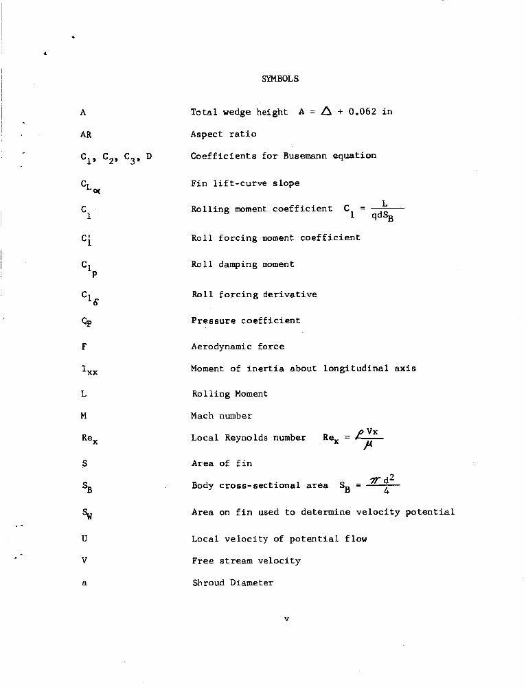
SYMBOLS
.-
P C l
T o t a l wedge height
Aspect r a t i o
C o e f f i c i e n t s f o r Busemann equat ion
A = A + 0.062 i n
Fin l i f t - c u r v e s l o p e
- L - ‘1 qdSB Rol l ing moment c o e f f i c i e n t
Rol l f o r c i n g moment c o e f f i c i e n t
Ro l l damping moment
Roll f o r c i n g d e r i v a t i v e
P r e s s u r e c o e f f i c i e n t
Aerodynamic f o r c e
Moment of i n e r t i a about l o n g i t u d i n a l a x i s
Rol l ing Moment
Mach number
Local Reynolds number
Area of f i n
Rex = e P
- T d 2 4 Body c r o s s - s e c t i o n a l area SB -
Area on f i n used t o determine v e l o c i t y p o t e n t i a l
Local v e l o c i t y of p o t e n t i a l f low
Free stream v e l o c i t y
Shroud Diameter
V

. 4
b Fin span
C F in chord
d Body diameter
h Wedge chord
m Wedge shape parameter
Roll ra te
Dynamic p res su re q = 1 / 2 p v 2
Fin semi- span s = 1/2b
Local v e l o c i t y i n x d i r e c t i o n
P
S
U
uo P e r t u r b a t i o n v e l o c i t y i n x d i r e c t i o n
X Coordinate p a r a l l e l t o l o n g i t u d i n a l a x i s
Y Coordinate normal to l o n g i t u d i n a l axis a long f i n
Coordinate normal t o f i n z
r Supersonic source s t r e n g t h
Wedge he igh t A = h t a n 6 A Rol l ang le
Angle of attack
Compress ib i l i ty f a c t o r (3 6 6'
Wedge ang le
Boundary l a y e r t h i ckness
F in t a p e r r a t i o A = 2 h
vi

P cr
E 7 ru P
ss
P
r
t
6
Local a i r deQs i ty
Fin mid-chord sweepback a n g l e
General chord-wise c o o r d i n a t e of p o i n t on f i n
General span-wise coord ina te of p o i n t on f i n
Local a i r v i s c o s i t y
V e l o c i t y p o t en t i a 1
SUBSCRIPTS
Steady- s t a g e
Roll
Root
Tip
Wedge
v i i

c
.
A THEORETICAL INVESTIGATION OF THE ROLLING MOTION OF THE N I K E CAJUN AND NIKE APACHE ROCKET VEHICLES
SUMMARY DJ- 72/ An attempt h a s ,been made t o t h e o r e t i c a l l y p r e d i c t t h e r o l l rate of
t h e second s t a g e of t h e Nike Cajun and Nike Apache sounding rocket vehi - c l e s . The one-degree-of-freedom r o l l equat ion w a s der ived. General express ions w e r e obtained f o r t h e r o l l damping c o e f f i c i e n t d e r i v a t i v e of a sounding rocke t i n both subsonic and supersonic f l i g h t . Analy t ic ex- p r e s s i o n s f o r t h e r o l l f o r c i n g moment c o e f f i c i e n t due t o f i n t r a i l i n g - e d g e wedges are p resen ted f o r t h e subsonic and supersonic f l i g h t regimes.
These equa t ions have been appl ied t o t h e Cajun and Apache v e h i c l e s and t h e r e s u l t s compared t o wind tunnel and f r e e - f l i g h t test results. The r o l l damping c o e f f i c i e n t s are i n e x c e l l e n t agreement wi th wind tunne l resul ts , bu t t h e r o l l f o r c i n g c o e f f i c i e n t s do no t agree. Nei ther t h e t h e o r e t i c a l nor t h e wind tunne l fo rc ing c o e f f i c i e n t s gave a r o l l h i s t o r y as obta ined i n f r e e - f l i g h t tests. The t h e o r e t i c a l l y p red ic t ed r o l l h i s - t o r y does, however, show s e v e r a l p rev ious ly unexplained c h a r a c t e r i s t i c s of the f r e e - f l i g h t - r o l l h i s t o r y .
I NT RO DU CTI 0 N
The Nike Cajun and Nike Apache are two-stage, unguided sounding rocke t s used by NASA f o r upper atmosphere and meteoro logica l research . The f i r s t s t a g e of both v e h i c l e s i s a s o l i d - p r o p e l l a n t Nike M5-El booster . f i r e d 16 seconds a f t e r f i r s t stage burnout and burns f o u r ( 4 ) seconds for t h e Cajun o r 6.5 seconds f o r the Apache. The Nike Cajun can l i f t an 80 pound payload approximately 100 m i l e s and t h e Nike Apache w i l l ach ieve an apogee of 150 m i l e s wi th t h e same payload.
Th i s boos t e r burns f o r 3.5 seconds. The second s t a g e i s
Except f o r t h e p r o p e l l a n t and the nozzle , t h e Cajun and t h e Apache A s t h e Cajun and Apache v e h i c l e s are geometr i - v e h i c l e s are i d e n t i c a l .
c a l l y i d e n t i c a l , aerodynamically they can be cons idered t o be t h e same veh ic l e , which i s usua l ly c a l l e d the Capache veh ic l e . w i l l be fol lowed h e r e a f t e r when r e f e r r i n g t o t h e gene ra l veh ic l e .
Th i s p r a c t i c e
The Capache v e h i c l e has a diameter of 6.5 inches and a f i n span of 25.5 inches. i s b e s t desc r ibed as swept-back and tapered wi th streamwise t i p s . normal second s t a g e Capache f l i g h t condi t igns t h e lead ing and t r a i l i n g edges a r e ' s u p e r s o n i c . of 7.5 inches .
I t i s equipped wi th four ( 4 ) cruc i form f i n s whose planform Under .
The f i n s are mounted on a shroud having a diameter F igure 1 i s a ske tch of t h e Capache vehic le .

. .
- 2-
As t h e Nike Cajun i s unguided i t must be s p i n - s t a b i l i z e d t o a t t a i n good payload a t t i t u d e i n space. by mounting s p i n t a b s o r wedges on t h e t r a i l i n g edges of a l l f o u r f i n s . The wedges extend f u l l span and r o l l rate c o n t r o l i s obta ined by changing t h e va lues of wedge a n g l e and wedge area. It i s most convenient t o u s e wedges of a given cons tan t chord, thereby reducing t h e c o n t r o l problem t o only one parameter , wedge he ight . i n F igu re 2.
Roll i s achieved i n t h e Capache v e h i c l e
Wedge dimensions and placement are shown
When t h e magnitudes of t h e r o l l rate and t h e p i t c h frequency are s i m i - Th i s coupl ing usua l ly r e s u l t s i n p i t c h - lar, a p i t c h - r o l l coupl ing occurs .
r o l l resonance o r "rol l lock-in". Rol l l ock - in produces uns t ab le f l i g h t and, i f t h e dynamic p r e s s u r e i s s u f f i c i e n t l y h igh , i s o f t e n c a t a s t r o p h i c . Ca lcu la t ions of t y p i c a l p i t c h f requencies show t h a t t h e t h e o r e t i c a l r i g i d body p i t c h frequency of t h e Capache v e h i c l e i s above 5 c y c l e s p e r second a t second s t a g e sepa ra t ion , decays t o 2 cyc le s p e r second a t second s t a g e i g n i t i o n , peaks a t 2.5 c y c l e s p e r second j u s t b e f o r e Capache burnout, and then decays a sympto t i ca l ly t o zero (F igure 3 ) .
Two methods are a v a i l a b l e f o r prevent ing p i t c h - r o l l resonance. The f i r s t i s to hold t h e r o l l rate as c l o s e t o zero as poss ib l e . however, o f t e n r e s u l t s i n poor veh ic l e a t t i t u d e i n space. I n o r d e r t o o b t a i n good a t t i t u d e i n space, t h e v e h i c l e must b e r o l l e d . To prevent r o l l lock- in t h e r o l l rate should pass through t h e lock- in po in t (where t h e r o l l rate and p i t c h frequency are equal) with as h igh a r o l l a c c e l e r a t i o n as poss ib l e . The r o l l ra te a t Capache burnout should a l s o be a t least 5 r p s t o prevent lock-in a t t h a t time.
This method,
DERIVATION OF THE ROLL EQUATION
The r o l l i n g motion of a rocke t v e h i c l e i s desc r ibed by t h e b a s i c dynamic equat ion
The r o l l i n g moment L i s t h e sum of t h r e e terms, t h e f o r c i n g moment, t he damping moment, and t h e induced moment. The f o r c i n g moment i s a func t ion of c o n t r o l d e f l e c t i f n (or wedge angle) 6 , t h e damping moment i s a f u n c t i o n of r o l l ra te , and t h e induced moment i s a f u n c t i o n of ang le of a t t a c k o( and r o l l a n g l e 4 . For t h e purposes of t h i s ana ly- sis, t h e ang le of a t t a c k i s assumed to b e ze ro so t h a t t h e r e are no i n - duced r o l l i n g moments. (For roll lock-in t o occur t h e r e must be induced
@
.

-3 -
r o l l i n g moments p re sen t , However, t h i s a n a l y s i s i s i n t e r e s t e d i n de te rmining t h e r o l l rate and i s not designed t o ana lyze r o l l lock-in o t h e r than t o avoid i t s occurrence,)
Under t h i s l i n e a r theory, two r o l l i n g moment c o e f f i c i e n t d e r i v a t i v e s are def ined. These d e r i v a t i v e s , t h e f o r c i n g d e r i v a t i v e and t h e damping d e r i v a t i v e are def ined as fo l lows:
(b) Damping moment c o e f f i c i e n t :
A
Theref ore ,
S u b s t i t u t i n g i n t o equat ion (11, s impl i fy ing and changing v a r i a b l e s g i v e s
Wind tunne l test results g i v e t h e t e r m Cj56 as a func t ion of Mach number. The t e r m i s def ined to b e i d e n t i c a l w i th c' for t h e purposes of t h i s a n a l y s i s . That i s , 4
C ' E C s 1 Q6 ( 6 )

- 4-
For a s t e a d y - s t a t e r o l l i n g motion
i f i s f i n i t e . Therefore,
Equat ions ( 5 ) and ( 8 ) have been p rogramed f o r s o l u t i o n on a d i g i t a l computer .
CALCULATION OF ROLL DAMPING COEFFICIENT
The next s t e p of t h e a n a l y s i s involves de te rmina t ion of t h e r o l l i n g moment c o e f f i c i e n t s . As t h e Capache v e h i c l e normally o p e r a t e s w i th t h e l ead ing edges of t h e f i n s supersonic , va lues of t h e c o e f f i c i e n t s f o r Mach numbers less than 1.4 are needed only to show t r e n d s and do n o t r e q u i r e a high degree of accuracy. Therefore , s imple s t r i p theory w i l l b e used f o r t h e subsonic regime.
Consider ing a chordwise s t r i p (F igu re 41,
S u b s t i t u t i n g f o r t h e gene ra l chord i n terms of t a p e r r a t i o and non- dirnensional iz ing g ives

- 5-
which, upon i n t e g r a t i n g r e s u l t s i n
Thus
For a f l a t p l a t e i n incompressible flow, t h e l i f t - c u r v e s l o p e i s 2 77-. Cor rec t ing for compress ib i l i t y , sweepback, and a s p e c t r a t i o (Ref, 1) t h e l i f t - c u r v e s l o p e becomes
Combining equa t ions (12) and 413) f o r a f o u r f i n n e d v e h i c l e g i v e s
The damping moment on a supersonic f i n i s g iven by
L =-& c, Y d Y dK P
where C i s an unknown fur 'ct ion, P
(15)

Thus,
- 6-
(17)
From t h e l i n e a r i z e d Bernoul l i equat ion,
2 p vu, c, = ? (18)
o r simply,
4 4 c,= v (19)
The p e r t u r b a t i o n v e l o c i t y i s most e a s i l y found by r ep lac ing t h e f i n wi th a d i s t r i b u t e d shee t of supersonic sources. i s then given by t h e X-der iva t ive of t h e v e l o c i t y p o t e n t i a l of t h e s e sources . That i s ,
The p e r t u r b a t i o n v e l o c i t y
- ( 2 0 )
uo - a x
Hence,
The v e l o c i t y p o t e n t i a l of t h e d i s t r i b u t e d sources i s (Ref. 21,

where i i s t h e source s t r e n g t h , a n d S, i s some region on t h e f i n def ined by i n t e r s e c t i o n s between t h e Mach forecone of t h e p o i n t (q , 9 1 and t h e edges of t h e f i n (F igure 5 ) . The pressure c o e f f i c i e n t i s t h e r e f o r e
n 4 r r \ \
For a r o l l i n g f i n a t z e r o angle of a t t a c k t h e source s t r e n g t h i s
r’7) V -- - I- -
Theref ore ,
, r r
Combining equat ion (25) with equation (17) g i v e s
(24)
The r a t h e r cumbersome i n t e g r a t i o n s of equat ion (26) have been c a r r i e d out by Malves tu to e t a1 (Ref. 3 ) f o r t h e case of subsonic lead ing edges and by Harmon and J e f f r e y s (Ref. 4) f o r t h e supersonic lead ing edges. both cases t h e r e s u l t s have been presented as des ign char t s . have been used h e r e to determine t h e damping moment c o e f f i c i e n t s as needed.
I n These c h a r t s
The above method, equat ion (261, n e g l e c t s t h e e f f e c t s of f in-body i n - t e r f e r e n c e . T h i s i s i n keeping wi th t h e s tandard p r a c t i c e of n e g l e c t i n g body e f f e c t s when t h e ra t io of body r r d l u s t o f i n semi-span is less than 0.30. modified t o
If i t is d e s i r a b l e t o i n c l u d e body e f f e c t s , equat ion (24) can be

-8-
f o r q < q ( R e f . 51,
t i o n s (13) and (26) w a s compared with d a t a taken i n wind-tunnel tests (Ref. 6).
The damping moment c o e f f i c i e n t f o r t h e Capache as computed from equa-
Exce l l en t agreement r e s u l t e d (F igure 6 ) ,
CALCULATION OF ROLL FORCING COEFFICIENT
The f low f i e l d over t h e wedge producing t h e f o r c i n g moment i s q u i t e complex, and s t r a igh t fo rward mathematical s o l u t i o n s are n o t a v a i l a b l e as above, The v a r i o u s Mach l i n e s emanating from t h e l ead ing edge r o o t and t i p i n t e r s e c t i n such a manner t h a t a t low Mach numbers none of t h e wedge exper iences two-dimensional f low, and a t h ighe r Mach numbers only a small p o r t i o n of t h e wedge exper iences two-dimensional f low (Figure 7). t o Evvard 's l i n e a r a e r o f o i l theory , however, t h e s e Mach l i n e s do no t a f f e c t t h e two-dimensional n a t u r e of t h e flow a t zero a n g l e of a t t ack . The only p o r t i o n of t h e wedge t h a t would dev ia t e from two-dimensional f low would be i n t h e r eg ions behind t h e Mach l i n e s emanating from t h e j u n c t i o n s of t h e lead ing edge of the wedge with t h e body and the t i p . n e g l i g i b l e when compared t o t h e t o t a l area of t h e wedge.
According
These reg ions are
A f u r t h e r complicat ion of the f low over t h e wedge i s due t o t h e presence of t h e boundary layer . By assuming t h a t a l o c a l Reynolds number of 5 x lo5 i s s u f f i c i e n t t o assure a t u r b u l e n t boundary l aye r , and making t h e added and r a t h e r g r o s s assumption t h a t t h e Inconel cap on t h e l ead ing edge of t h e f i n a c t s as a t r i p , t h e genera l statement can be made t h a t t h e boundary l a y e r i n t h e v i c i n i t y of t h e wedge i s of a f u l l y developed t u r b u l e n t na ture .
For the purpose of boundary layer c a l c u l a t i o n s , a 1/5 power v e l o c i t y d i s t r i b u t i o n w a s assumed f o r the tu rbu len t boundary layer :
For t h i s v e l o c i t y d i s t r i b u t i o n the boundary l a y e r t h i ckness i s (Ref. 7 )
I .

A boundary l a y e r t h i ckness h i s t o r y w a s prepared f o r a t y p i c a l Apache
Th i s p o i n t i s t h e p o i n t of minimum boundary l a y e r t h i ckness on t h e t r a j e c t o r y using t h e boundary layer t h i ckness a t t h e t i p of t h e t r a i l i n g edge, wedge. From t h i s h i s t o r y (F igu re 8) it w a s determined t h a t , even a t mini- mum boundary l a y e r th ickness , t h e boundary l a y e r t h i ckness i s g r e a t e r than wedge height .
Another p o i n t t o be considered i s boundary l a y e r separa t ion i n the compression co rne r formed by t h e i n t e r s e c t i o n of t h e wedge with t h e f i n . Th i s s epa ra t ion and t h e subsequent reattachment produce an a d d i t i o n a l shock wave. o t h e r ob l ique shock i s formed a t the reat tachment point . from t h e i d e a l f low case of one obl ique shock extending from t h e corner. Kuehn (Ref. 8) has measured t h e p re s su re d i s t r i b u t i o n s produced by sepa- r a t i o n of t u r b u l e n t boundary layers i n such corners . By numerical ly i n t e g r a t i n g t h e measured p r e s s u r e d i s t r i b u t i o n to o b t a i n t h e r e s u l t a n t f o r c e p e r u n i t width, i t has been determined t h a t viscous e f f e c t s i n genera l reduced t h e r e s u l t a n t f o r c e a c t i n g by 5% from t h e i d e a l va lue , r e g a r d l e s s of whether s epa ra t ion occurs i n t h e corner. be gene ra l ly ignored i n computing fo rc ing moments.
An ob l ique shock i s formed at t he sepa ra t ion p o i n t and an- Th i s d e v i a t e s
Thus, boundary l a y e r e f f e c t s w i l l
The aerodynamic f o r c e on t h e wedge i s given by I
and t h e r o l l i n g moment i s
For incompressible flow,

- 10-
by B e r n o u l l i ' s equa t ion . From p o t e n t i a l f l o w t h e o r y ( R e f . 91,
m u= V.X where
Thus,
m = n - 6
26
(33)
(34)
P C
f o r i n c o m p r e s s i b l e f l o w . b le subsonic f l o w g i v e s
Applying t h e P r a n d t l - G l a u e r t r u l e f o r compressi-
. -
S u b s t i t u t i n g i n t o equat ion (31) g ives
and hence
2 2 s -a l h - 7T+6 "I

-11-
as t h e f o r c i n g moment c o e f f i c i e n t for subsonic flow.
The p r e s s u r e c o e f f i c i e n t f o r supersonic f low is i n gene ra l given by Busemann's o b l i q u e shock equat ion f o r two-dimensional flow:
Two approximations t o t h e Busemann equat ion are i n use. i s the well-known Ackeret equat ion
The l i n e a r form
and a t h i r d - o r d e r form due t o Bonney (Ref, 10) i s
n
L, - %
Both approximations were used wi th equat ion (31) t o gene ra t e f o r c i n g moment c o e f f i c i e n t s . It w a s found t h a t the l i n e a r form gave a b e t t e r
... agreement wi th t h e wind tunne l data. S u b s t i t u t i n g equat ion (40) i n t o equat ion (31) and i n t e g r a t i n g g ives
o r

- 12-
The f o r c i n g moment genera ted by equat ions (38) and ( 4 3 ) i s p l o t t e d i n F igu re 9, a long wi th wind tunne l data f o r a r e p r e s e n t a t i v e va lue of 6 Agreement between t h e o r e t i c a l and wind tunne l d a t a i s n o t good.
.
RESULTS
Both t h e o r e t i c a l and wind tunnel f o r c i n g moment c o e f f i c i e n t s w e r e used t o p r e d i c t t h e r o l l h i s t o r i e s of s eve ra l Capache f l i g h t s . Nei ther s e t of c o e f f i c i e n t s produced a r o l l h i s t o r y which agreed wi th t h e measured fP-Lght r o l l rate (F igu re 10) . A t some p o r t i o n s of t h e f l i g h t t h e p r e d i c t e d saiLes were as milch as 60% i n e r r o r compared to t h e f l i g h t measured values . a t t empt s 20 c o r r e l a t e t h e d i f f e r e n c e s between p r e d i c t e d r o l l rates and meastred f l i g h t va lues wi th f l i g h t parameters have f a i l e d .
A l l
Severa l e f f e c t s are probably r e spons ib l e f o r t h e s e d iscrepancles . There Fs evidence t h a t a e r o e l a s t i c and j e t plumage e f f e c t s have a s t r o n g e f f e c t on t h e f l i g h t r o l l rate. Also t h e e f f e c t of t h e boundary l a y e r ?& t h e r o l l rate cannot be discounted. Boundary l a y e r w a s ignored i n t h e t h e o r e t i c a l c a l c u l a t i o n s c a r r i e d out here . The Reynolds number i n t h e wind tunnel tests w a s much lower than t h e f l i g h t Reynolds numbers. Thus, i n t h e wind tunne l tests, t h e boundary l a y e r bui ld-up w a s n o t r e p r e s e n t a t i v e of f l i g h t cases .
CONCLUSIONS
1. Although t h e equat ions der ived h e r e do n o t g i v e a h igh ly a c c u r a t e dezc r%pt ioz of t h e r o l l h i s t o r y of t h e Nike Capache vehfc l e i 2 f l i g h t , they are a d e f i n i t e improvement on t h e equa t ions used by Cooper and Mamone (Ref. 11) and by Jenk ins (Ref. 12).
2. The equa t ions , as der ived here , wh i l e no t a c c u r a t e enough f o r a ro l l lock - in s tudy , do g ive s u f f i c i e n t l y a c c u r a t e r o l l rate p r e d i c t i o n s f o r gene ra l use i n p lanning t h e payload requirements f o r t h e experiment and t h e t e l eme t ry

- 13-
REFERENCES
1, Shapi ro , Ascher H, , The Dynamics and Thermodynamics of Compressible F l u i d Flow, Volume 1, Ronald P r e s s , New York, 1953,
2. Evvard, John C., NACA TN 1382, " D i s t r i b u t i o n of Wave Drag and L i f t i n t h e V i c i n i t y of Wing T i p s a t Supersonic Speeds", Washington, J u l y 1947,
3, Malves tu to , Frank S., Jr., Kenneth Margol i s , and Herber t S. Ribner , NACA Rept. 970, " T h e o r e t i c a l L i f t and Damping i n Roll a t Supersonic Speeds of Thin Sweptback Tapered Wings w i t h Streamwise T i p s , Sl;bsor.ic Leading Edges, and Supersonic T r a i l i n g Edges", Washington, 1950.
4. Harmon, Sidney M. and I s a b e l l a J e f F r e y s , NACA TN 2114, " T h e o r e t i c a l L i f t and Damping i n Roll of Thin Wings w i t h A r b i t r a r y Sweep and Taper a t Supersonic Speeds, Supersonic Leading and T r a i l i n g Edges", Washington, May 1950.
5. Tucker, Warren A, and Robert 0. P i l a n d , NACA TN 2151, "Es t imat ion of t h e Damping i n R o l l of Supersonic- lead ing-edge Wing-body Combinations", Washington, J u l y 1950.
6. Fa langa , Ralph A, , NASA TN D-2576, "Supersonic I n v e s t i g a t i o n o f a Spinning and Nonspinning Model of a Cajun ( o r Apache) Rocket V e h i c l e w i t h R o l l - c o n t r o l Tabs", Washington, J a n u a r y 1965.
7. Tabakoff , Widen, Unpublished L e c t u r e s on "Viscous Flow", U n i v e r s i t y of C i n c i n n a t i , 1963.
8. Kuehn, Donald M . , NASA MEMO 1-21-59Aa "Experimental I n v e s t i g a t i o n of t h e P r e s s u r e R i s e Required f o r the I n c i p i e n t S e p a r a t i o n of T u r b u l e n t Scundary Layers i n Two-Dimensional Supersonic Fiow", Washington, February 1959.
9. S c h l i c h t i n g , Hermann, Boundary Layer Theory, 4 t h Edz, M c G r a w - H i l l , New York, 1960.
10. Bonney, E. A r t h u r , Engineer ing Supersonic Aerodynamics, M c G r a w - H i l l , New York, 1950.
11. Cooper, E a r l and R u s s e l l Mamone, A t l a n t i c Research C o r p o r a t i o n , Space V e h i c l e s Group Report 7903-2-01, " F e a s i b i l i t y Study Nike Apache Rocket System w i t h F i b e r g l a s s Payload", Pasadena, C a l i f o r n i a , 30 A p r i l 1961.
12. J e n k i n s , Reed B., "Cajun-Apache Rol l Rate", Unpublished Repor t , Goddard Space F l i g h t Center .

I I
,1 lo
-6.75"
1
- 6.5"
1
Figure 1 - Gpacne Vehicle
15

B
c VIEW A - A
DETAIL B I 0.062"
Figure 2- Spin Tab
16

. -
17

Figure 4- Strip Theory On Fins
18

Figure 5 - Coordinate System onl Fin
19

n
r Z
1 I I I 1 I 0 (Y
I I
0 0 0 8 W 0 * -4
I -
I I I i
d 1N313133303 3NldWVa 1108 - '3
20

M=1.75
Figure 7a- Mach Lines for Flow Over Fin
\
21

.
_ -
e
M=6.0
Figure 7b- Mach Lines for Flow Over Fin
22

.
23

--1 w Z 5 I-
o
I I I I 1 I I I I 1 I I ? - - 0 7 2 0 ? r ? - ? m
o o o d lN313133303 9N13103 1101 - :3
2
u)
m
cy
e w
P 3 Z I U
, Q z
8
t 0
cy 0
3
24

.
,
.
, I -
I I I I I 0 c * c) N 0 v)
. aN033S 2l3d 5313D-31W 1 1 0 U