
of in - U.S. Silica in AFS Safety & Health ... This manual was prepared under the direction of the...
80
of in AFS Safety & Health Committee (10Q) Principal Author: Robert C. Scholz, PE, CIH Contributing Authors: Thomas J. Slavin, CIH, CSP, CPEA, CSHM Kay Rowntree, CIH
Transcript of of in - U.S. Silica in AFS Safety & Health ... This manual was prepared under the direction of the...
of
in
AFS Safety & Health Committee (10Q)
Principal Author:
Robert C. Scholz, PE, CIH
Contributing Authors:
Thomas J. Slavin, CIH, CSP, CPEA, CSHMKay Rowntree, CIH

Control of Silica Exposure in Foundries
November 2007
AFS Safety and Health Committee (10-Q)
Principal Author
Robert C. Scholz, PE, CIH
Contributing Authors Thomas J. Slavin, CIH, CSP, CPEA, CSHM
Kay Rowntree, CIH
With Case Histories by:
Kennedy Valve
Arne Feyling
Mike Mazuir
Tom Shaw
Wescast Industries, Inc.
Michelle Schaefer
Acme Foundry, Inc.
Don Pusa
Mark McCullough
Grede Foundries, Inc.
Peter Mark
This document was developed as a product of the American Foundry Society (AFS)/Occupational Safety
and Health Administration (OSHA) Alliance.
Published and distributed
by the
American Foundry Society
Schaumburg, Illinois 60173
www.afsinc.org
Copyright © 2007
ISBN 978-0-87433-312-1
Printed in the United States of America All rights reserved. No part of this book may be reproduced in any form or by any means, electronic, mechanical, photocopying, recording or otherwise, without prior permission of the publisher. The American Foundry Society, Inc., as a body, is not responsible for the statements and opinions advanced in this publication. Nothing contained in any publication of the Society is to be construed as granting right, by implication or otherwise, for manufacture, sale or use in connection with any method, apparatus or product covered by letters patent, nor as insuring anyone against liability for infringement of letters patent. Edited by Susan P. Thomas/AFS
i
Table of Contents
Purpose .....................................................................................................................................................iii
Foreword ...................................................................................................................................................v
1. Silica in the Foundry ..............................................................................................................1-1
1.1 Silica (Quartz) is Common................................................................................................1-1
1.2 If it is Just Sand Why is it Hazardous?............................................................................1-3
1.3 Size Matters.........................................................................................................................1-6
1.4 Size Matters II .....................................................................................................................1-9
1.5 Dust Exposure Limits ........................................................................................................1-9
1.6 Historical Exposure Levels .............................................................................................1-10
1.7 Summary ...........................................................................................................................1-14
2. How to Manage Silica Exposure in Foundries ..............................................................2-1
2.1 Why is Monitoring Important? ........................................................................................2-1
2.2 Understanding Exposure Risk .........................................................................................2-2
2.3 Data Gathering and Review .............................................................................................2-3
2.4 Identifying Employees with Similar Exposures and Obtaining Data ........................2-7
2.5 Interpreting the Results.....................................................................................................2-8
2.6 Recordkeeping and Working with Industrial Hygiene Consultants..........................2-8
2.7 Respiratory Protection for Silica ......................................................................................2-9
2.8 Medical Surveillance Programs for Employees Exposed to Silica ............................2-12
3. How to Identify and Control Sources of Silica Dust Exposure ................................3-1
3.1 Real-Time Dust Exposure Monitoring ............................................................................3-1
3.2 Respirable Dust Concentration Mapping of the Workplace........................................3-3
3.3 Scope of Exposure Control Methods ...............................................................................3-5
3.4 Exposure Control Focuses on Process and Material Handling ...................................3-6
3.5 Ventilation of Silica Dust Sources ....................................................................................3-7
3.6 Silica Exposure Control Program Strategy .....................................................................3-8
ii
List of Tables
Table 1-1 Settling Rate for Quartz Particles in Still Air.............................................................1-9
Table 2-1 Silica Nomenclature and Materials that may Contain Crystalline Silica ..............2-3
Table 2-2 Foundry Process Variables Affecting Silica Exposure Potential ............................2-4
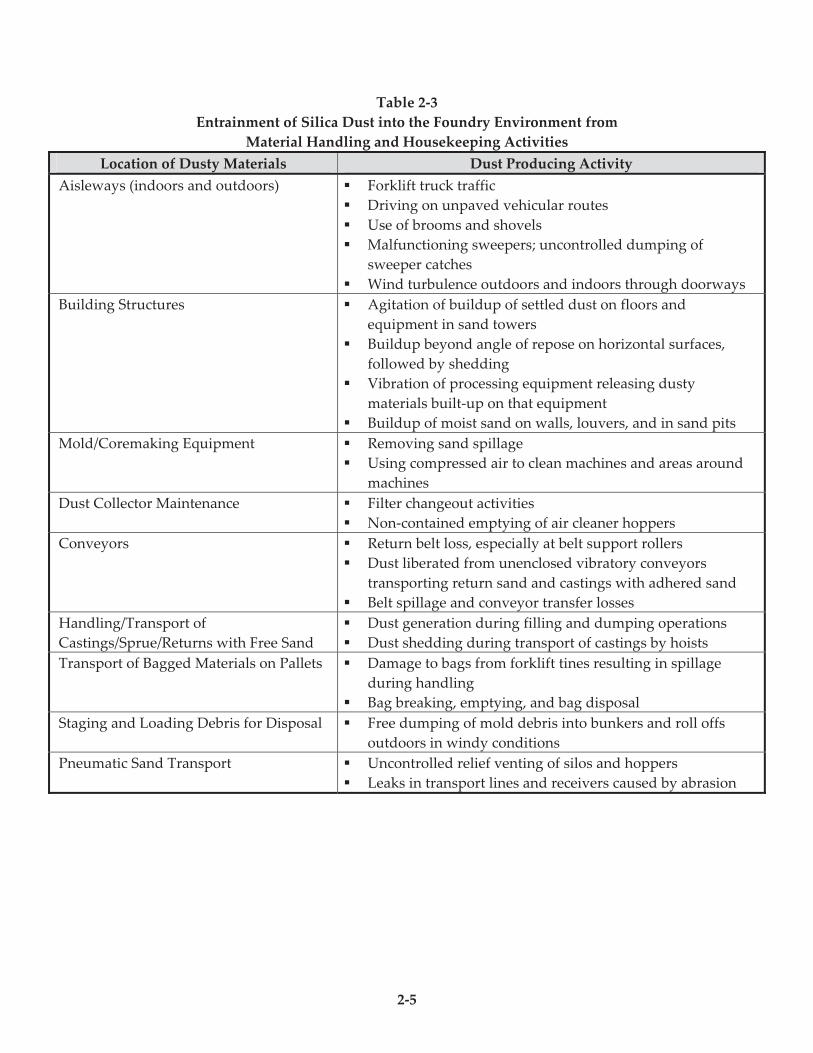
Table 2-3 Entrainment of Silica Dust into the Foundry Environment from Material
Handling and Housekeeping Activities ....................................................................2-5
Table 2-4 OSHA's Assigned Protection Factors .......................................................................2-11
List of Figures
Figure 1-1 Quartz is a form of crystalline silica ...........................................................................1-2
Figure 1-2 The lungs provide a very large surface areafor the exchange of oxygen and
carbon dioxide between the body and the environment.........................................1-5
Figure 1-3 Number of deaths of U.S. residents aged 15 or older with silicosis recorded
as an underlying or contributing cause on the death certificate ............................1-7
Figure 1-4 Silicosis: Most frequently recorded industries on death certificate,
U.S. residents aged 15 and over, selected states and years .....................................1-8
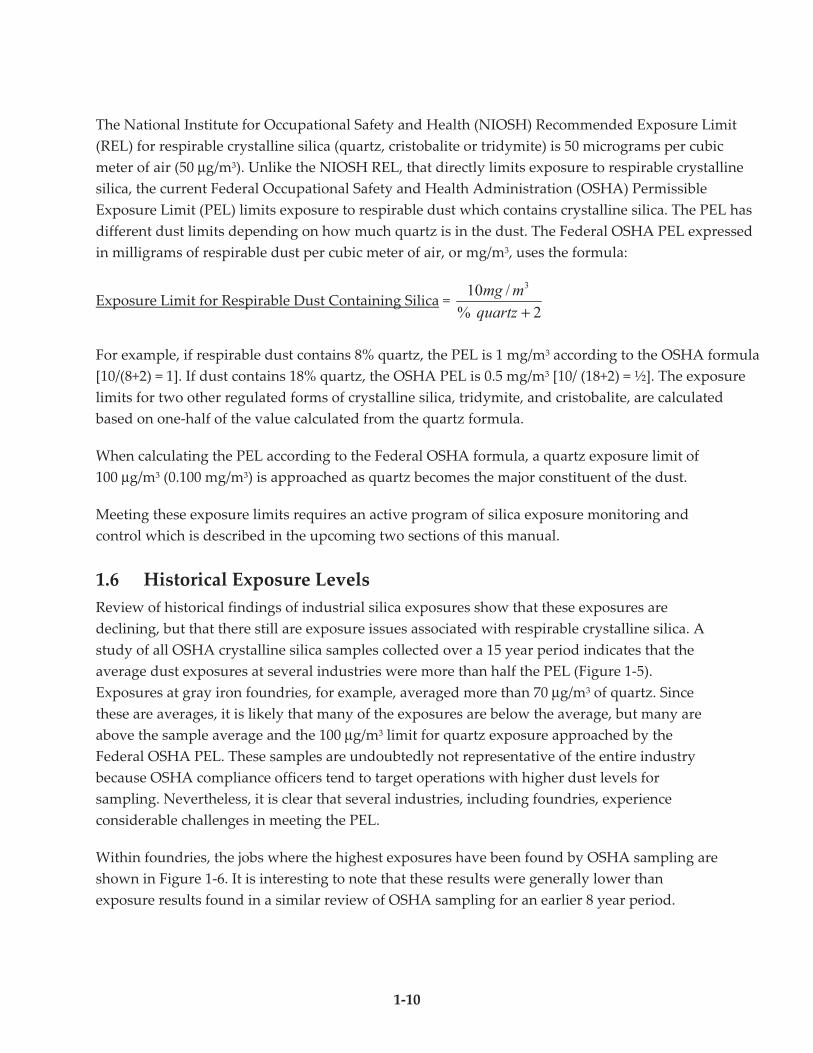
Figure 1-5 Crystalline silica exposure levels measured by OSHA for several industries ...1-11
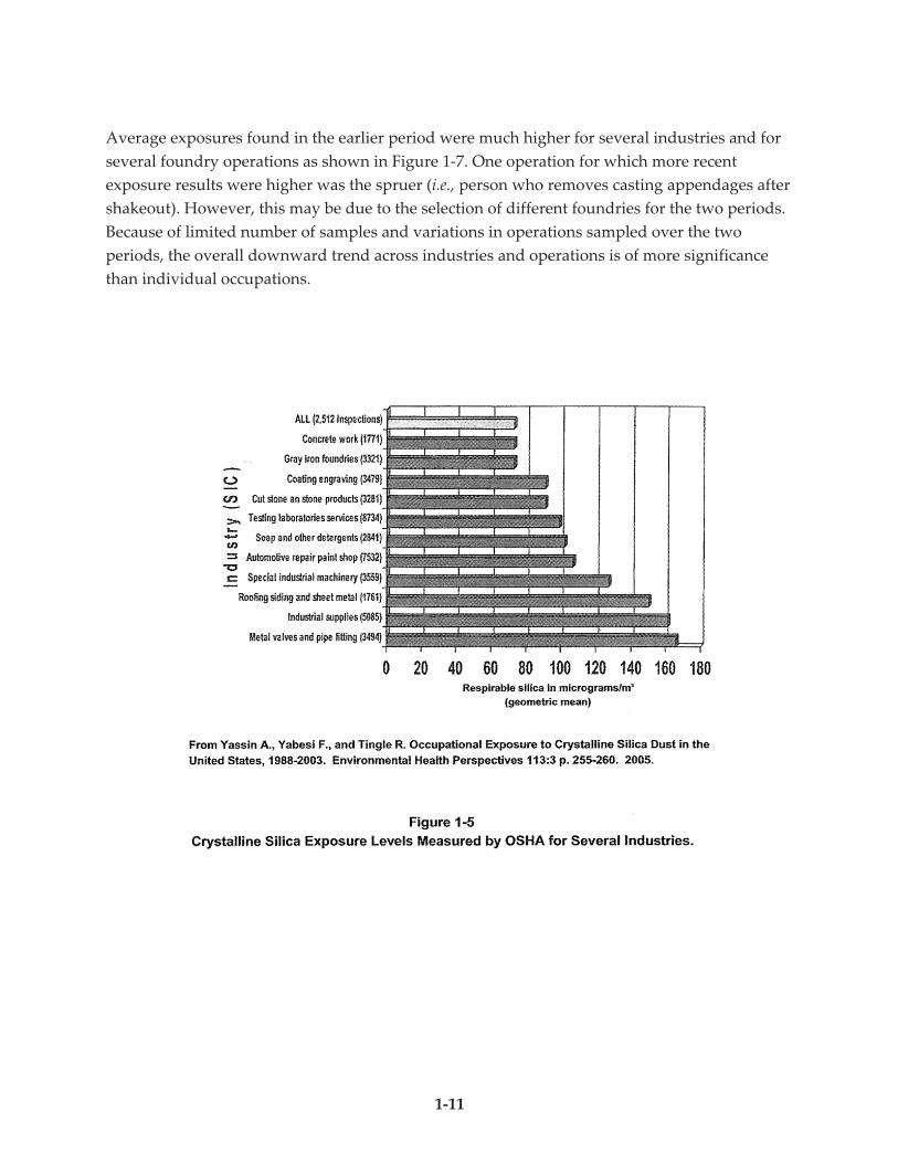
Figure 1-6 Crystalline silica exposure levels measured by OSHA for several
foundry operations .....................................................................................................1-12
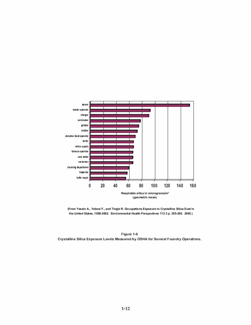
Figure 1-7 Reduction in crystalline silica exposures measured by OSHA
over two different time periods ................................................................................1-13
Figure 3-1 Worker is wearing a portable real-time monitor for respirable dust ....................3-2
Figure 3-2 Standing profile of respirable particulate matter in a foundry facility .................3-4
Figure 3-3 Air contaminant exposure control program ...........................................................3-10
List of Case Histories
Case History A—Silica Dust Control Improvement: Grinding of Iron Castings with Portable Tools,
Kennedy Valve—Elmira, New York .....................................................................A-1
Case History B—Heat Relief and Improved Air Quality in Foundries,
Westcast Industries, Inc.—Wingham, Ontario, Canada..................................... B-1
Case History C—Clearing the Air at Acme Foundry: Integrated Engineering Design of a New Casting
Cleaning and Finishing Facility, Acme Foundry, Inc.—Coffeyville, Kansas ...... C-1
Case History D—Ventilation Upgrade Reduces Silica Exposure at Grede Foundries, Inc.,
Grede Foundries, Inc.—Reedsburg, Wisconsin ...................................................D-1
iii
Purpose
This document was developed as a product of the American Foundry Society
(AFS)/Occupational Safety and Health Administration (OSHA) Alliance. This manual was
prepared under the direction of the AFS Safety and Health Committee (10-Q) to provide
foundries with information that can help control the potential hazards of respirable crystalline
silica. Silica exposure control has been pursued by foundries for many years. This publication is
intended to provide useful technical information for foundries and to show how important it is
to share best practices in the control of worker exposures to silica.

iv
v
Foreword
This manual focuses on the essential elements for success of any air contaminant exposure control
program in industry: management commitment; worker involvement; hazard assessment and
communication; exposure monitoring; operational and maintenance procedures for the process
and its ventilation; housekeeping; respiratory protection and medical monitoring.
Limiting silica exposures is an ongoing process, not something that is done once and put to rest.
A coordinated program is warranted, with planning and review, similar to any effective
program of quality control.
Case histories are a unique contribution of this publication. The authors of these case histories
represent a class of foundry professionals who have a clear vision of how the work environment
should be managed. Their dedication to the cause of creating a healthy and safe foundry
environment is manifested in their writing. A sincere thank you goes out to these professionals.
A special appreciation goes to principal author Bob Scholz and contributing authors Tom Slavin
and Kay Rowntree whose technical knowledge and skills are shared with the metal casting
industry. Additionally, our thanks also go out to the following individuals who served as
reviewers.
AFS 10-Q Safety and Health Committee
Jim Barry, P.E.
Greg Hillmann, CIH
Gary Mosher, CIH
The AFS 10-Q Committee meets quarterly and is open to persons committed to foundry safety
and health who either work at foundries or who serve the needs of foundries. The committee is
always looking for new members to carry on our mission with efforts such as this one to
support the need for updated information and guidance.
Fredrick H. Kohloff, CSHM
Director, Environmental Health & Safety
American Foundry Society, Inc.

vi
1-1
Section 1
Silica in the Foundry Thomas J. Slavin CIH, CSP, CPEA, CSHM
International Truck & Engine Corp., Warrenville, IL
The same sand that fills a child’s sand box is associated with the risk of silicosis in foundry
operations. How can this be? Are children safe when playing in the sand at home or on the
beach? If so, why is silica exposure a risk to foundry workers? All this and more will be
explained in this section.
1.1 Silica (Quartz) is Common
Silica occurs virtually everywhere on the earth’s surface. It is present in most rock, gravel, sand,
and soil. Lake or river bed sand that is used in many foundries is about 95 percent silica; granite
contains 25 to 40 percent silica, shale 22 percent and sandstone 67 percent. The form of silica in
all of these materials is quartz, a crystalline structure. Two other crystalline forms of silica are
less common, namely: cristobalite and tridymite.
Cristobalite can sometimes be encountered in a foundry because it can be formed by very high
temperature conversion of quartz. Cristobalite is also encountered as an ingredient in some core
washes and refractory materials. In both cases, cristobalite is most likely to show up in cleaning
room dust exposures and during refractory removal. Tridymite is not usually found in
foundries.
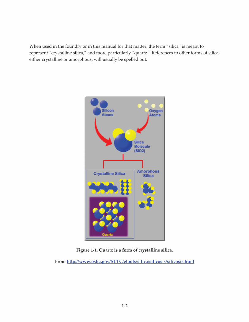
To complete the picture, silica (chemically silicon dioxide or SiO2) also occurs in non-crystalline or
amorphous forms as shown in Figure 1-1. Glass is one example of an amorphous form. Glass is
made by heating crystalline silica until it becomes molten and then rapidly cooling it to prevent
crystallization. Another example of amorphous silica is diatomaceous earth, which consists of the
fossilized remains of diatoms (microscopic unicellular marine or freshwater colonial algae having
cell walls impregnated with silica). Diatomaceous earth is now used for a variety of purposes
including filtration. Diatomaceous earth can also be converted to crystalline silica (cristobalite) by
calcining or applying very high heat.
There is a tendency to employ verbal conservation (shortcuts in terminology) when discussing
crystalline silica. The predominant health hazards and associated health standards all involve
crystalline silica, principally quartz that is respirable (i.e., small enough in size to be able to be
drawn into the gas-exchange region of the lung).
1-2
When used in the foundry or in this manual for that matter, the term “silica” is meant to
represent “crystalline silica,” and more particularly “quartz.” References to other forms of silica,
either crystalline or amorphous, will usually be spelled out.
Figure 1-1. Quartz is a form of crystalline silica.
From http://www.osha.gov/SLTC/etools/silica/silicosis/silicosis.html
1-3
1.2 If It Is Just Sand Why Is It Hazardous?
Quartz has been associated with several health problems, but the principal concern is silicosis.
Silicosis is a progressive, disabling lung disease caused by breathing dust containing respirable
particles of crystalline silica. The silica particles become lodged in the air sacs of the lung,
causing inflammation and scarring that damages the sacs. Consequently, the free exchange of
oxygen and carbon dioxide is prevented between the blood and the air. Small bonded masses
called nodules form and over time the nodules grow, making breathing increasingly difficult.
Other symptoms may include severe and chronic cough, fatigue, loss of appetite, chest pains,
and fever.
The particle size, dust concentration and duration of dust exposure are important factors which
determine the extent of the development of silicosis. NIOSH has classified three types of
silicosis: acute, accelerated and chronic.
! Chronic silicosis is the most common form and typically develops after more than 10
to 20 years of exposure. Symptoms can range from very mild to disabling or even
fatal.
! Accelerated silicosis, although rare, can occur with high exposures over a period of
time from 5 to 15 years. Symptoms are the same as chronic or ordinary silicosis
except that they appear sooner and can progress rapidly. Similar symptoms of
scarring and inflammation progress faster in accelerated silicosis than chronic
silicosis. Accelerated silicosis usually leads to death within a few years of its
development.
! Acute silicosis can occur with exposure to very high concentrations occurring in a
short period of time ranging from a few weeks to 5 years. It occurs in occupations
such as sandblasting and tunnel work. Again, the disease occurs in the same way as
chronic or ordinary silicosis, except much faster and is almost always fatal.
The human body has developed amazing defense mechanisms against toxic materials. In the
upper respiratory system, the tissues of the nose and throat are lined with cilia and coated with
a thin layer of mucous. The cilia are hair-like structures that work together to push the mucous
along and force it to flow up and out of the respiratory system. The airways of the upper
respiratory system have several bends and turns. Larger particles tend to travel in a straight line
instead of following the twists and turns of the airway and so they end up striking the side of
the airway and getting carried along the mucous stream. That is why when people are exposed
to a dusty environment they often notice deposits of dust in their nose several hours later as the
mucociliary escalator slowly eliminates the particles.
1-4
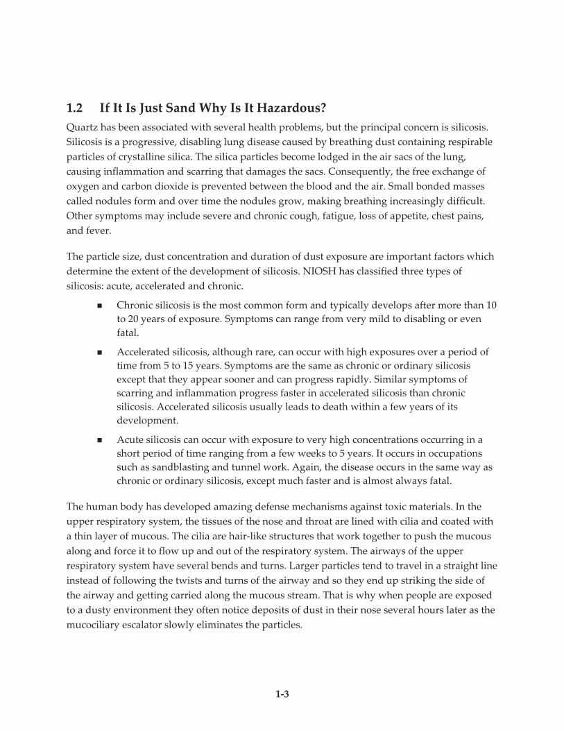
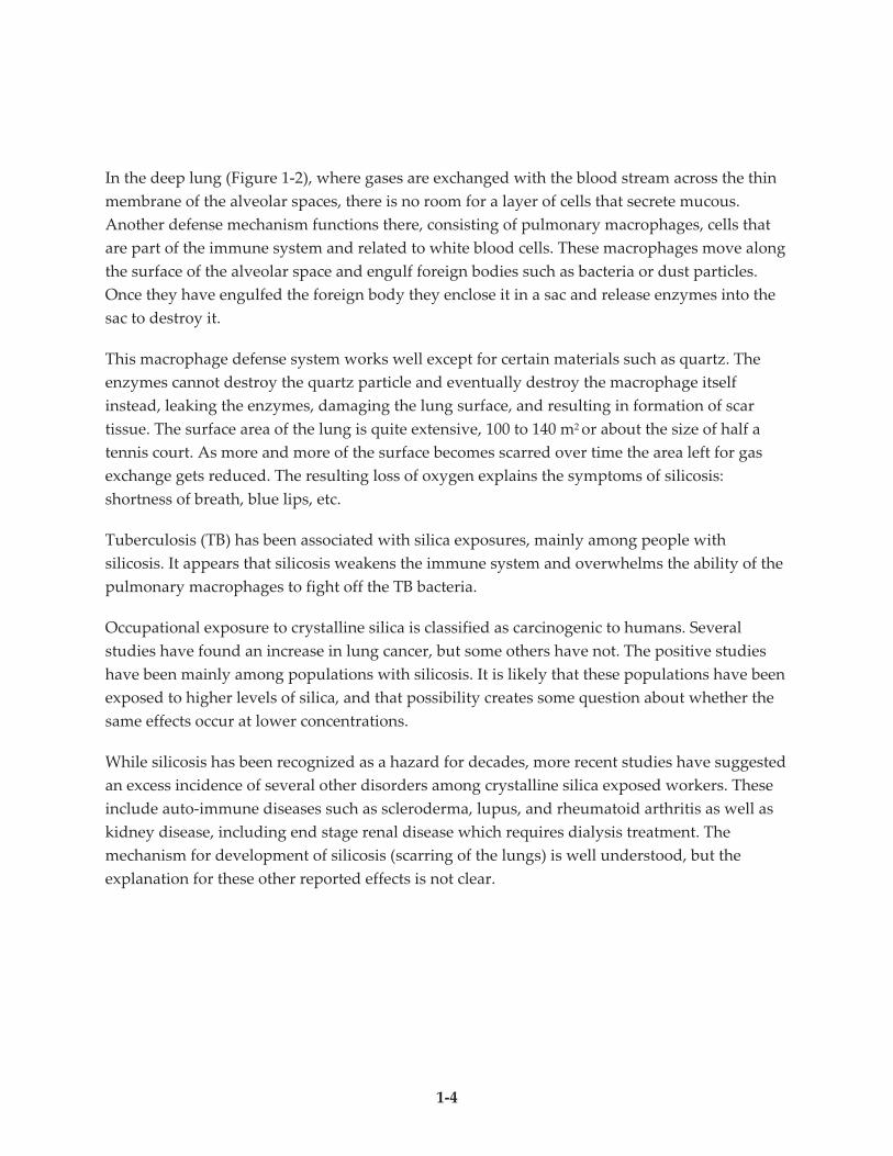
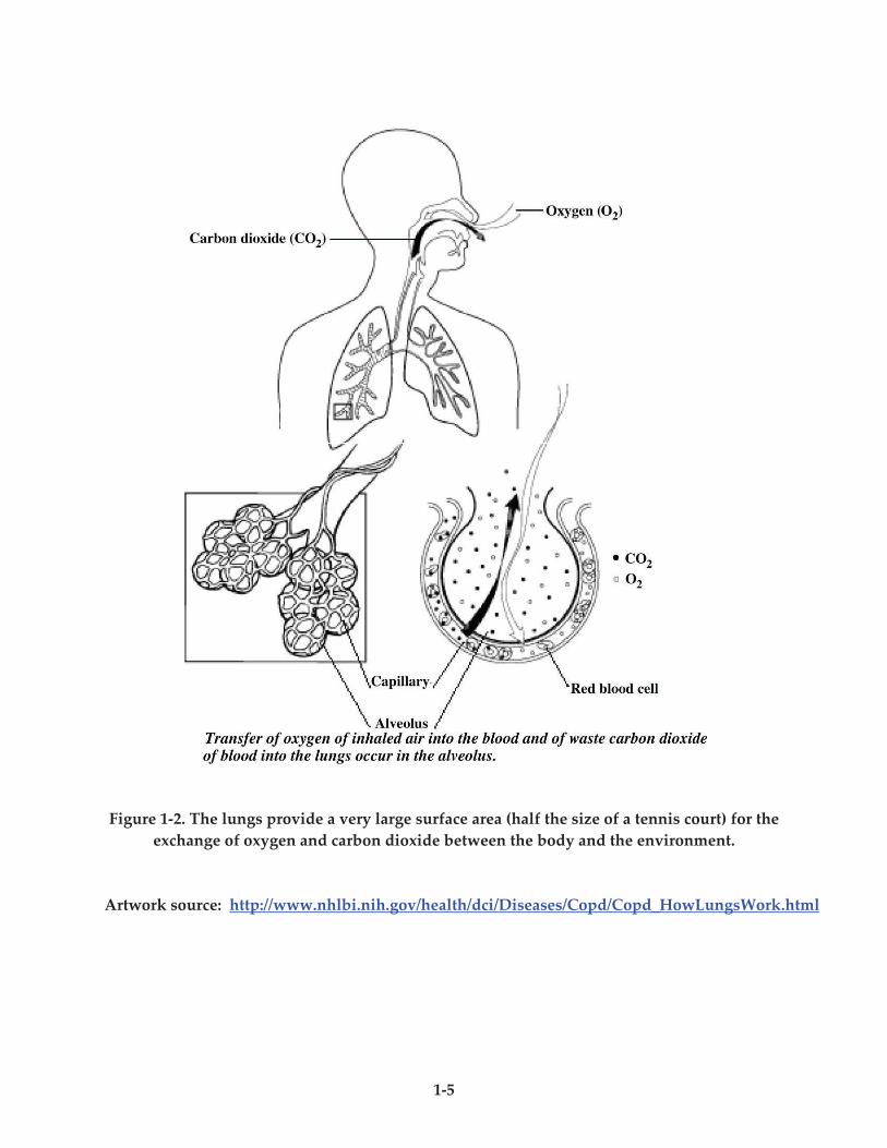
In the deep lung (Figure 1-2), where gases are exchanged with the blood stream across the thin
membrane of the alveolar spaces, there is no room for a layer of cells that secrete mucous.
Another defense mechanism functions there, consisting of pulmonary macrophages, cells that
are part of the immune system and related to white blood cells. These macrophages move along
the surface of the alveolar space and engulf foreign bodies such as bacteria or dust particles.
Once they have engulfed the foreign body they enclose it in a sac and release enzymes into the
sac to destroy it.
This macrophage defense system works well except for certain materials such as quartz. The
enzymes cannot destroy the quartz particle and eventually destroy the macrophage itself
instead, leaking the enzymes, damaging the lung surface, and resulting in formation of scar
tissue. The surface area of the lung is quite extensive, 100 to 140 m2 or about the size of half a
tennis court. As more and more of the surface becomes scarred over time the area left for gas
exchange gets reduced. The resulting loss of oxygen explains the symptoms of silicosis:
shortness of breath, blue lips, etc.
Tuberculosis (TB) has been associated with silica exposures, mainly among people with
silicosis. It appears that silicosis weakens the immune system and overwhelms the ability of the
pulmonary macrophages to fight off the TB bacteria.
Occupational exposure to crystalline silica is classified as carcinogenic to humans. Several
studies have found an increase in lung cancer, but some others have not. The positive studies
have been mainly among populations with silicosis. It is likely that these populations have been
exposed to higher levels of silica, and that possibility creates some question about whether the
same effects occur at lower concentrations.
While silicosis has been recognized as a hazard for decades, more recent studies have suggested
an excess incidence of several other disorders among crystalline silica exposed workers. These
include auto-immune diseases such as scleroderma, lupus, and rheumatoid arthritis as well as
kidney disease, including end stage renal disease which requires dialysis treatment. The
mechanism for development of silicosis (scarring of the lungs) is well understood, but the
explanation for these other reported effects is not clear.
1-5
Figure 1-2. The lungs provide a very large surface area (half the size of a tennis court) for the
exchange of oxygen and carbon dioxide between the body and the environment.
Artwork source: http://www.nhlbi.nih.gov/health/dci/Diseases/Copd/Copd_HowLungsWork.html
1-6
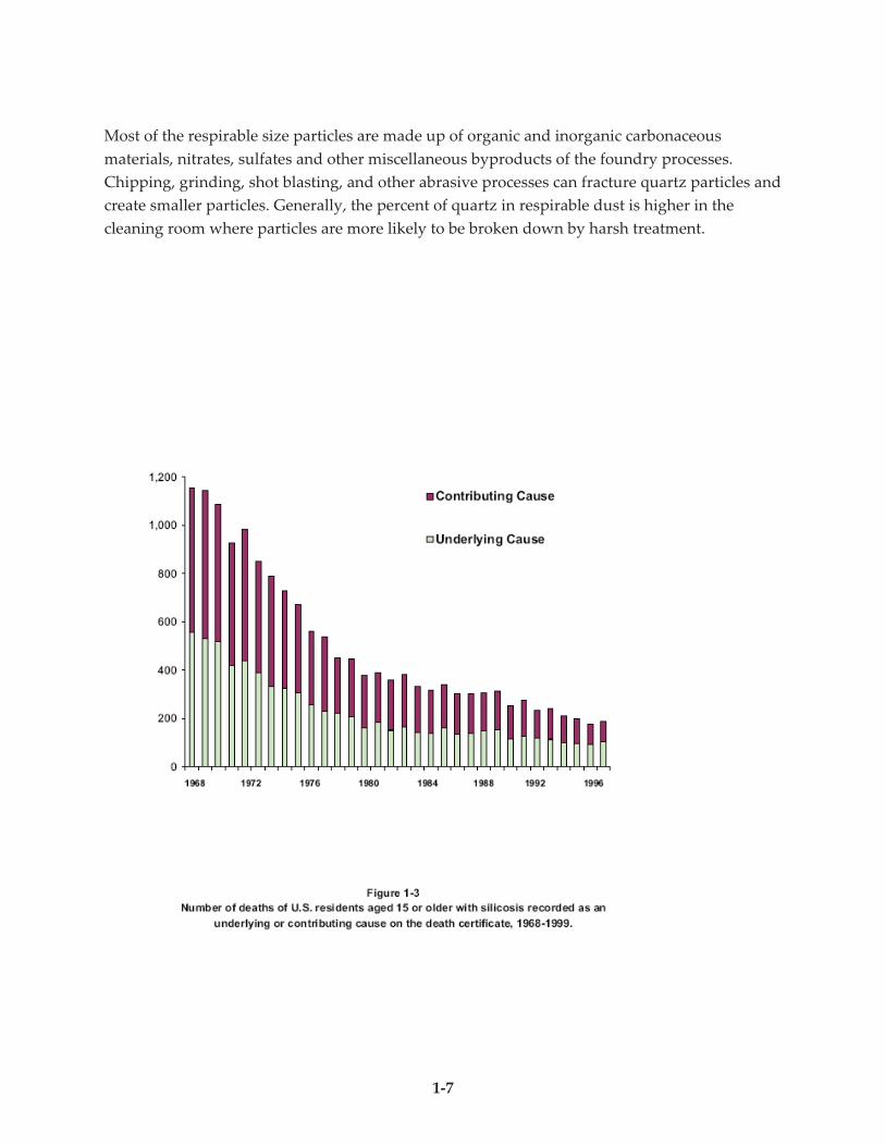
The good news is that silicosis-related deaths have been declining according to Centers for
Disease Control (CDC) records. Figure 1-3 shows that for 1968 to 1999 deaths due to silicosis as
a primary or contributing cause declined from 1,200 to about 200 per year. The chart may
underestimate the number of deaths because not every state is included in the report, but the
clear downward trend is the key point.
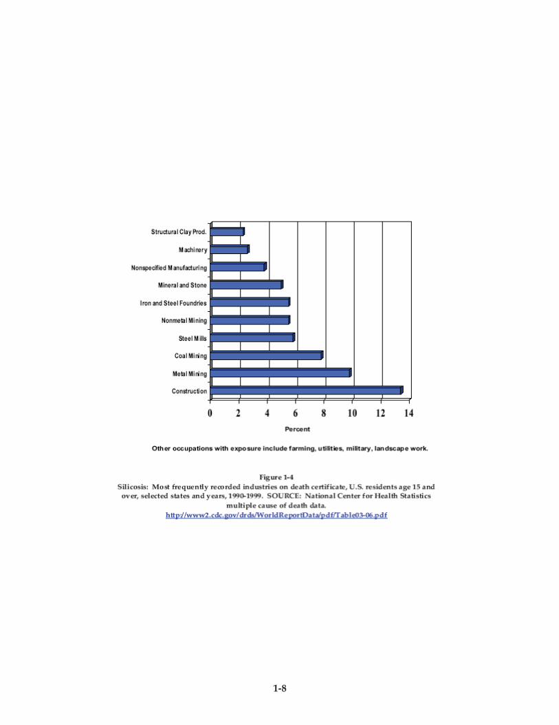
In an analysis of occupationally associated deaths, foundry work was one of the more common
occupations reported on silicosis death certificates (Figure 1-4). Construction and mining were
cited more often. Both of these industries have developed and implemented better dust controls
such as wet cutting methods and better substitutes for silica sand in abrasive blasting
operations, so it is hoped that the number of silicosis deaths will decline.
1.3 Size Matters
Back to the initial question of why quartz is hazardous to those exposed at work, but not in a
child’s sand box. The answer comes mainly down to particle size. Particle size is important
because only very small particles, which we refer to as respirable size particles, reach the deep
areas of the lung where scarring occurs. The sand particles on a beach or river bank are mostly
much larger than this. The foundry air contains a mixture of large quartz particles and some
smaller particles that have been reduced in size by various foundry processes.
Particles as large as 100 microns can be inhaled, but most of these are trapped in the nose and
throat. A micron is 1 micrometer or 1 millionth of a meter. Particle sizes down to 10 microns are
deposited in the upper (thoracic) region of the respiratory system. To reach the deep lung a
particle must be about 5 microns or less in diameter. To put that in perspective, a human hair is
about 75 microns in diameter and the limit of visibility with the naked eye is 50 microns.
Therefore, if a particle is big enough to be visible it is too big to reach the deep lung. An exception
to that rule is created by something called the Tyndall effect, whereby a light beam such as a ray
of sunlight shining through a crack in the side of a barn reflects off tiny specks of dust as small as
2 microns and illuminates them. Small particles illuminated by a light beam in this manner often
appear to be floating rather than falling.
Quartz sand particles are very large in physiologic terms and so hard that they are not easily
broken down into smaller particles that can be inhaled and travel to the deep lung. Although
more than 95 percent of the incoming sand may be quartz, the respirable dust in a foundry
typically contains only around 0 to 15 percent quartz.
1-7
Most of the respirable size particles are made up of organic and inorganic carbonaceous
materials, nitrates, sulfates and other miscellaneous byproducts of the foundry processes.
Chipping, grinding, shot blasting, and other abrasive processes can fracture quartz particles and
create smaller particles. Generally, the percent of quartz in respirable dust is higher in the
cleaning room where particles are more likely to be broken down by harsh treatment.
1-8
1-9
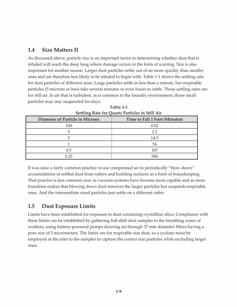
1.4 Size Matters II
As discussed above, particle size is an important factor in determining whether dust that is
inhaled will reach the deep lung where damage occurs in the form of scarring. Size is also
important for another reason. Larger dust particles settle out of air more quickly than smaller
ones and are therefore less likely to be inhaled to begin with. Table 1-1 shows the settling rate
for dust particles of different sizes. Large particles settle in less than a minute, but respirable
particles (5 microns or less) take several minutes or even hours to settle. Those settling rates are
for still air. In air that is turbulent, as is common in the foundry environment, those small
particles may stay suspended for days.
Table 1-1
Settling Rate for Quartz Particles in Still Air
Diameter of Particle in Microns Time to Fall 1 Foot (Minutes)
100 0.02
5 2.5
2 14.5
1 54
0.5 187
0.25 590
It was once a fairly common practice to use compressed air to periodically “blow down”
accumulations of settled dust from rafters and building surfaces as a form of housekeeping.
That practice is less common now as vacuum systems have become more capable and as more
foundries realize that blowing down dust removes the larger particles but suspends respirable
ones. And the intermediate sized particles just settle on a different rafter.
1.5 Dust Exposure Limits
Limits have been established for exposure to dust containing crystalline silica. Compliance with
these limits can be established by gathering full-shift dust samples in the breathing zones of
workers, using battery-powered pumps drawing air through 37 mm diameter filters having a
pore size of 5 micrometers. The limits are for respirable size dust, so a cyclone must be
employed at the inlet to the sampler to capture the correct size particles while excluding larger
ones.
1-10
The National Institute for Occupational Safety and Health (NIOSH) Recommended Exposure Limit
(REL) for respirable crystalline silica (quartz, cristobalite or tridymite) is 50 micrograms per cubic
meter of air (50 µg/m3). Unlike the NIOSH REL, that directly limits exposure to respirable crystalline
silica, the current Federal Occupational Safety and Health Administration (OSHA) Permissible
Exposure Limit (PEL) limits exposure to respirable dust which contains crystalline silica. The PEL has
different dust limits depending on how much quartz is in the dust. The Federal OSHA PEL expressed
in milligrams of respirable dust per cubic meter of air, or mg/m3, uses the formula:
Exposure Limit for Respirable Dust Containing Silica = 2%
/103
+quartz
mmg
For example, if respirable dust contains 8% quartz, the PEL is 1 mg/m3 according to the OSHA formula
[10/(8+2) = 1]. If dust contains 18% quartz, the OSHA PEL is 0.5 mg/m3 [10/ (18+2) = ½]. The exposure
limits for two other regulated forms of crystalline silica, tridymite, and cristobalite, are calculated
based on one-half of the value calculated from the quartz formula.
When calculating the PEL according to the Federal OSHA formula, a quartz exposure limit of
100 µg/m3 (0.100 mg/m3) is approached as quartz becomes the major constituent of the dust.
Meeting these exposure limits requires an active program of silica exposure monitoring and
control which is described in the upcoming two sections of this manual.
1.6 Historical Exposure Levels
Review of historical findings of industrial silica exposures show that these exposures are
declining, but that there still are exposure issues associated with respirable crystalline silica. A
study of all OSHA crystalline silica samples collected over a 15 year period indicates that the
average dust exposures at several industries were more than half the PEL (Figure 1-5).
Exposures at gray iron foundries, for example, averaged more than 70 µg/m3 of quartz. Since
these are averages, it is likely that many of the exposures are below the average, but many are
above the sample average and the 100 µg/m3 limit for quartz exposure approached by the
Federal OSHA PEL. These samples are undoubtedly not representative of the entire industry
because OSHA compliance officers tend to target operations with higher dust levels for
sampling. Nevertheless, it is clear that several industries, including foundries, experience
considerable challenges in meeting the PEL.
Within foundries, the jobs where the highest exposures have been found by OSHA sampling are
shown in Figure 1-6. It is interesting to note that these results were generally lower than
exposure results found in a similar review of OSHA sampling for an earlier 8 year period.
1-11
Average exposures found in the earlier period were much higher for several industries and for
several foundry operations as shown in Figure 1-7. One operation for which more recent
exposure results were higher was the spruer (i.e., person who removes casting appendages after
shakeout). However, this may be due to the selection of different foundries for the two periods.
Because of limited number of samples and variations in operations sampled over the two
periods, the overall downward trend across industries and operations is of more significance
than individual occupations.
1-12
1-13

1-14
Summary
Although quartz is a very common material, it poses little risk unless it is fractured into
respirable size particles that can reach the deep lung and cause scarring. Industrial processes
such as mining, construction and foundries can produce exposures to fine quartz particles that
cause silicosis, a disabling and often deadly disease. The good news is that the incidence of
silicosis related deaths has dramatically declined over the past 40 years. In addition, the levels
of occupational exposure to quartz have also declined over the past 20 years. Given that there is
a long latency period between exposure and development of disease, it is likely that lowered
exposure levels of the past 20 years will result in even lower incidence of silicosis in the years to
come. Furthermore, if workplaces could all comply with the OSHA PEL (in 1998 and 1999 more
than 40 percent of OSHA crystalline silica samples exceeded the PEL) occupational exposures
would continue to decline and the incidence of silicosis would be reduced even further in the
future.
2-1
Section 2
How to Manage Silica Exposure in Foundries Kay Rowntree, CIH
Industrial Hygiene Sciences LLC, Waterford, WI
Health damage to foundry workers from exposure to respirable crystalline silica can be
prevented through a consistent program of identifying and monitoring employees at risk, and
then using the means available to control exposures. Important aspects of an industrial hygiene
program to protect workers are presented in this section.
2.1 Why is Monitoring Important?
The potential hazard of respirable silica dust to the lungs relates to how much silica dust is
breathed, which is not the same for every foundry worker. The parameter typically used to
describe the quantity of dust breathed is the average concentration of respirable dust in the
breathing zone, along with its silica content. This data is referred to as time-weighted average
(TWA) exposure and it is gathered with instruments worn by the worker while doing the job.
Measuring the TWA silica exposure should be the mainstay of all silica exposure management
programs for foundries. This sampling allows a foundry to prioritize exposure control
initiatives on the basis of health risk.
Collecting representative air samples for silica is an essential part of protecting employee
health. While dusty operations may obviously need to be controlled, most managers need to see
data (usually air monitoring data) to decide if a new or improved control measure is necessary.
Air monitoring is important for the following reasons:
! to determine which employees need to be protected and how much protection is
necessary
! to assess whether controls are effective or are remaining effective
! to evaluate whether work practices need to be changed to reduce exposures
! to comply with OSHA regulations. If exposures are over OSHA PELs, there is an
expectation on OSHA’s part that employees will be protected with personal protective
equipment until feasible engineering controls or work practice changes can reduce
exposures below the PEL.
2-2
Evaluating and managing employee exposures to silica seems like it should be a straight
forward task: pick an employee to monitor, the employee wear a sampling device, obtain the
results, decide whether the employee is overexposed and then select controls that will reduce
exposures. But have the right employees been selected to monitor? How many times do you
need to monitor a job? Has the correct sampling procedure been used? What does the data
mean? These are critical questions to answer if the data obtained is going to be used to
determine if additional protective measures are needed to reduce employee risk.
Silica exposures are not uniformly distributed in a foundry. Developing a systematic approach
to assessing exposures and then managing the risk will help direct industrial hygiene and
control resources to those exposures of most concern. The following are steps that can be used
to assess exposures:
! Understand the exposure risk
! Use prescribed methods to take samples
! Identify similar exposure groups
! Obtain data from these different exposure groups
! Interpret the data properly and use it to make decisions about reducing risk
2.2 Understanding Exposure Risk
It is clear that the risk of developing silica related disease is related to the concentration of
crystalline silica or quartz in the dust. Materials that contain more crystalline silica therefore
present a higher risk than those with lower percentages of silica. This does not mean, however,
that low silica content materials do not create exposures. If enough dust is generated by a
process, overexposures can still occur.
At times, identifying where silica exposures can occur is quite easy - dust is seen and exposure is
assumed - but there are many exposures that are less obvious or infrequent and therefore easily
overlooked. Absence of visible dust does not mean there is not exposure (see Subsection 1.3). In
addition, the confusing nature of silica terminology makes it easy to miss potential exposures
when reviewing materials used in foundries.
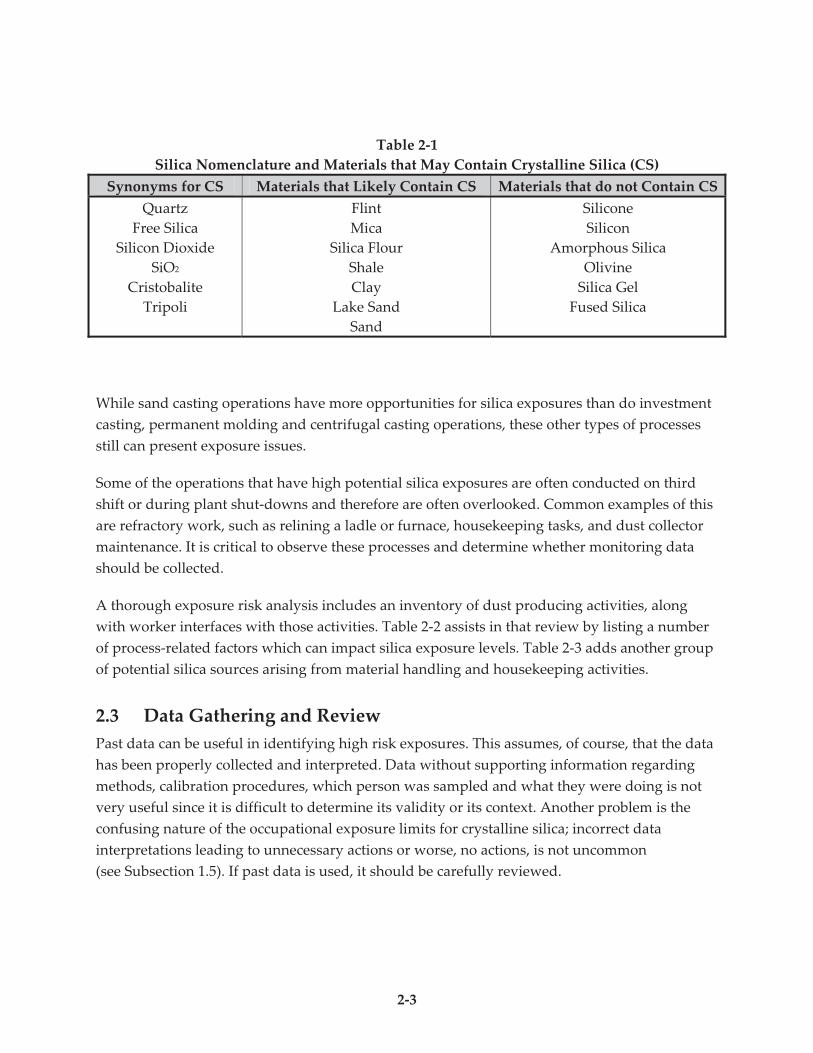
Table 2-1 lists materials that may contain crystalline silica as well as acronyms used for
crystalline silica. Material Safety Data Sheets (MSDS), if well prepared, should indicate whether
or not a material contains crystalline silica. Unfortunately, not all MSDSs clearly identify
whether or not crystalline silica is present in the product.
2-3
Table 2-1
Silica Nomenclature and Materials that May Contain Crystalline Silica (CS)
Synonyms for CS Materials that Likely Contain CS Materials that do not Contain CS
Quartz
Free Silica
Silicon Dioxide
SiO2
Cristobalite
Tripoli
Flint
Mica
Silica Flour
Shale
Clay
Lake Sand
Sand
Silicone
Silicon
Amorphous Silica
Olivine
Silica Gel
Fused Silica
While sand casting operations have more opportunities for silica exposures than do investment
casting, permanent molding and centrifugal casting operations, these other types of processes
still can present exposure issues.
Some of the operations that have high potential silica exposures are often conducted on third
shift or during plant shut-downs and therefore are often overlooked. Common examples of this
are refractory work, such as relining a ladle or furnace, housekeeping tasks, and dust collector
maintenance. It is critical to observe these processes and determine whether monitoring data
should be collected.
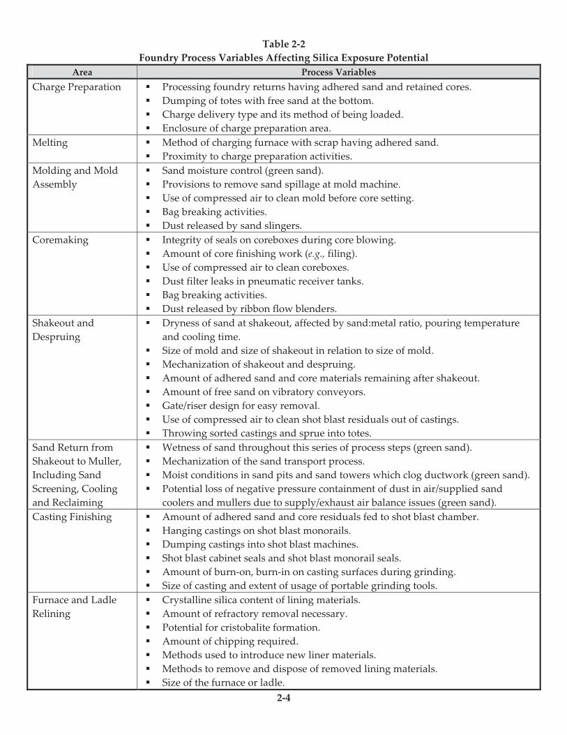
A thorough exposure risk analysis includes an inventory of dust producing activities, along
with worker interfaces with those activities. Table 2-2 assists in that review by listing a number
of process-related factors which can impact silica exposure levels. Table 2-3 adds another group
of potential silica sources arising from material handling and housekeeping activities.
2.3 Data Gathering and Review
Past data can be useful in identifying high risk exposures. This assumes, of course, that the data
has been properly collected and interpreted. Data without supporting information regarding
methods, calibration procedures, which person was sampled and what they were doing is not
very useful since it is difficult to determine its validity or its context. Another problem is the
confusing nature of the occupational exposure limits for crystalline silica; incorrect data
interpretations leading to unnecessary actions or worse, no actions, is not uncommon
(see Subsection 1.5). If past data is used, it should be carefully reviewed.
2-4
Table 2-2
Foundry Process Variables Affecting Silica Exposure Potential
Area Process Variables
Charge Preparation " Processing foundry returns having adhered sand and retained cores.
" Dumping of totes with free sand at the bottom.
" Charge delivery type and its method of being loaded.
" Enclosure of charge preparation area.
Melting " Method of charging furnace with scrap having adhered sand.
" Proximity to charge preparation activities.
Molding and Mold
Assembly
" Sand moisture control (green sand).
" Provisions to remove sand spillage at mold machine.
" Use of compressed air to clean mold before core setting.
" Bag breaking activities.
" Dust released by sand slingers.
Coremaking " Integrity of seals on coreboxes during core blowing.
" Amount of core finishing work (e.g., filing).
" Use of compressed air to clean coreboxes.
" Dust filter leaks in pneumatic receiver tanks.
" Bag breaking activities.
" Dust released by ribbon flow blenders.
Shakeout and
Despruing
" Dryness of sand at shakeout, affected by sand:metal ratio, pouring temperature
and cooling time.
" Size of mold and size of shakeout in relation to size of mold.
" Mechanization of shakeout and despruing.
" Amount of adhered sand and core materials remaining after shakeout.
" Amount of free sand on vibratory conveyors.
" Gate/riser design for easy removal.
" Use of compressed air to clean shot blast residuals out of castings.
" Throwing sorted castings and sprue into totes.
Sand Return from
Shakeout to Muller,
Including Sand
Screening, Cooling
and Reclaiming
" Wetness of sand throughout this series of process steps (green sand).
" Mechanization of the sand transport process.
" Moist conditions in sand pits and sand towers which clog ductwork (green sand).
" Potential loss of negative pressure containment of dust in air/supplied sand
coolers and mullers due to supply/exhaust air balance issues (green sand).
Casting Finishing " Amount of adhered sand and core residuals fed to shot blast chamber.
" Hanging castings on shot blast monorails.
" Dumping castings into shot blast machines.
" Shot blast cabinet seals and shot blast monorail seals.
" Amount of burn-on, burn-in on casting surfaces during grinding.
" Size of casting and extent of usage of portable grinding tools.
Furnace and Ladle
Relining
" Crystalline silica content of lining materials.
" Amount of refractory removal necessary.
" Potential for cristobalite formation.
" Amount of chipping required.
" Methods used to introduce new liner materials.
" Methods to remove and dispose of removed lining materials.
" Size of the furnace or ladle.
2-5
Table 2-3
Entrainment of Silica Dust into the Foundry Environment from
Material Handling and Housekeeping Activities
Location of Dusty Materials Dust Producing Activity
Aisleways (indoors and outdoors) " Forklift truck traffic
" Driving on unpaved vehicular routes
" Use of brooms and shovels
" Malfunctioning sweepers; uncontrolled dumping of
sweeper catches
" Wind turbulence outdoors and indoors through doorways
Building Structures " Agitation of buildup of settled dust on floors and
equipment in sand towers
" Buildup beyond angle of repose on horizontal surfaces,
followed by shedding
" Vibration of processing equipment releasing dusty
materials built-up on that equipment
" Buildup of moist sand on walls, louvers, and in sand pits
Mold/Coremaking Equipment " Removing sand spillage
" Using compressed air to clean machines and areas around
machines
Dust Collector Maintenance " Filter changeout activities
" Non-contained emptying of air cleaner hoppers
Conveyors " Return belt loss, especially at belt support rollers
" Dust liberated from unenclosed vibratory conveyors
transporting return sand and castings with adhered sand
" Belt spillage and conveyor transfer losses
Handling/Transport of
Castings/Sprue/Returns with Free Sand
" Dust generation during filling and dumping operations
" Dust shedding during transport of castings by hoists
Transport of Bagged Materials on Pallets " Damage to bags from forklift tines resulting in spillage
during handling
" Bag breaking, emptying, and bag disposal
Staging and Loading Debris for Disposal " Free dumping of mold debris into bunkers and roll offs
outdoors in windy conditions
Pneumatic Sand Transport " Uncontrolled relief venting of silos and hoppers
" Leaks in transport lines and receivers caused by abrasion
2-6
Common errors found in silica data include:
! Not using size separation devices (i.e., cyclones) to collect the dust samples or using
incorrect flow rates when using cyclones
! Lack of calibration data
! Assuming respirable dust and respirable quartz (or silica) are the same. They are
not! Respirable silica is only one component of respirable dust (see Subsection 1.3).
Because only respirable particles are of interest for silica exposures, a size selective sampling
device, a cyclone, which separates out particles by size, is necessary to collect silica samples.
Various types of cyclones are available, all operating in a similar manner but each collecting
slightly different ranges of particle sizes. Large particles spin out of the air stream and settle out
in the bottom of the cyclone while the smaller, respirable sized particles stay in the airstream
and get deposited on a collection filter. In this way, the larger, separated particles are excluded
from the exposure sample. The speed of the air stream going into the cyclone is critical in
determining where the size break will occur. Each manufacturer of cyclones specifies a flow rate
that must be used for that particular cyclone in order to ensure that only the respirable fraction
of dust is collected on the filter. For example, the MSA 10 mm nylon cyclone uses a flow rate of
1.7 lpm (liters per minute) while the SKC aluminum cyclone uses 2.5 lpm. Flow rates that are
higher than the cyclone rating cause more particles to drop out of the air stream, including
some of the respirable ones. Conversely, flow rates that are less than the cyclone rating allow
some larger particles to pass through and be collected on the filter as respirable particles. Past
data should be reviewed to find out how it was collected. If past sampling data was not
collected using cyclones with the correct flow rate for that specific cyclone, the data cannot be
relied upon.
The flow rate is determined through the use of a precision calibration device that measures
airflow through the collection device. To have accurate data, the calibration device used must
be a primary standard or be traceable back to a primary standard. Devices such as soap bubble
meters (both automatic and manual), frictionless calibrators or rotometers that are periodically
certified against a primary standard are reliable methods of calibration. The flow rate gauge on
an air sampling pump, if one is provided, may or may not be accurate - even these need to be
verified each time they are used to ensure they are correct. Air sampling records should specify
the calibration method used and, again, if that information is not available, the data collected
may be questionable.
Samples are analyzed by a laboratory for the amount of respirable dust on the filter (weight
gain, reported as milligrams per cubic meter), the amount of respirable quartz or silica (reported
2-7
as milligrams per cubic meter) and the percent of silica in the sample. The respirable quartz value
can then be compared to the American Conference of Governmental Industrial Hygienists
(ACGIH) Threshold Limit Value (TLV) or to the OSHA PEL for respirable quartz in certain
states that have state OSHA programs. For comparison with the Federal OSHA PEL, the
amount of respirable dust (quartz plus non-quartz) is used (see Subsection 1.5).
TWA sampling, by its very nature, is limited in its ability to identify silica exposure sources,
since it averages the contributions of all dust sources in the air that the worker breathes.
However, visual surveillance of workers throughout the workshift and time study of their
activities and locations, when combined with TWA sampling results and worker feedback, can
produce insights into probable sources of dust exposure. Analyzing the sources of silica dust
exposure is further pursued in Section 3 which follows.
Gaining a good understanding of a dust exposure requires more detailed observation of the
sampling activity than simply assuring that the sampling apparatus is functioning properly.
This distinction should be kept in mind when providing instructions to exposure sampling
personnel. Further discussion of conditions for gathering meaningful exposure samples are
presented under the topic of baseline exposure monitoring in Subsection 3.4.
TWA sampling as an industrial hygiene tool is intended to evaluate all of the activities
conducted during the workshift, whether they are operational, maintenance, or housekeeping.
2.4 Identifying Employees with Similar Exposures and Obtaining Data
It is not necessary to sample every worker but it is well known that an individual’s work
practices can impact the results of sampling. For example, one employee doing a refractory
relining task may not place a ventilation duct close to the point of dust generation while another
does. One employee may use compressed air to blow off equipment while another does not.
Observations can help explain differences in air sampling results and also determine which
workers are represented by the sample.
For small foundries, it may be necessary to sample a large percentage of workers because they
might be doing unique tasks. For large operations, sampling everyone is not cost effective and
the selection of workers must be made based on an understanding of the processes and the
variables that impact exposures. For example, if there are 20 employees cleaning castings, some
working on large castings, others on small ones, some working with downdraft booths and
others with no ventilation, sampling of an employee in each of those four different subgroups
would be reasonable since their silica exposures could vary. More certainty could be obtained
by sampling two or more employees in each group to help deal with individual variability in
work practices.
2-8
How often employees should be sampled is a difficult question to answer. It is better to base
decisions on observations or process changes than to base it on a calendar schedule (e.g.,
quarterly or annual monitoring). Clearly, if an operation has changed, exposures could also
have changed and remonitoring is important. Beyond that, some priorities for remonitoring are
as follows:
! Jobs where exposures exceeded the PEL, especially those that were much higher than
the PEL.
! Jobs which had exposures close to the PEL, another approach is that jobs/tasks where
exposures were 50 percent or more of the PEL should be remonitored.
! Jobs where, during previous sampling, conditions did not represent “typical”
exposures for that task/job or where foundry production activities in general were not
typical.
! Jobs where observations indicate an individual’s work practices may be different than
others doing the same task.
2.5 Interpreting the Results
Variability rather than consistency is the norm in industrial hygiene sampling and it is not wise
to base control judgments on only one set of samples. If a task/job shows that exposures are
clearly over the PEL, it is easier to make the decision that action is necessary, although repeat
sampling to validate the results is still useful. If exposures are well below the PEL, additional
control improvements may not be warranted as long as it is certain that the results represent the
range of exposures that could occur for the task/job. For example, if an employee has a low
result but one of the dusty processes he or she normally performs was not done on the day of
sampling, then it is risky to make a decision not to improve exposure controls any further. As
the results converge on the PELs, decision making becomes more difficult and more data is
advised to be certain that an appropriate decision is being made especially with regard to the
need for personal protection (i.e., respirators).
In all cases, employees must be informed of the results of the sampling and any actions
warranted by the sampling results. Moreover, employers must maintain records of the
sampling and allow workers access to those records (CFR 1910.1020).
2.6 Recordkeeping and Working with Industrial Hygiene Consultants
While some foundries may decide to collect their own air sampling data, others will rely upon
industrial hygiene consultants to collect the data for them, interpret results and prepare reports.
2-9
No matter who collects the data, it is important that the person understand the need to prepare
a good sampling strategy, carry out that strategy and interpret the results correctly.
Detailed notes are essential to understanding the meaning of sampling data. Sample data that
consists of the laboratory report without any supporting information about what went on
during the sampling can create problems. For example, high dust concentrations may be due to
a malfunctioning ventilation system on the day samples were taken. If that critical information
is not captured in notes, the employer may conclude that additional ventilation is necessary.
Conversely, a dusty job may only run for half of a shift due to a production upset; thus lowering
average exposure over the workshift. A field data collection form should be prepared and used
to record data about who was sampled, equipment used, times of sampling, conditions of
sampling, calibration data, unusual things that may have taken place during the sampling
period and other observations. This data form should become part of the permanent exposure
record that also includes the laboratory report, chain of custody or laboratory submission form
and any other pertinent information. Exposure monitoring records need to be maintained for 30
years to meet the requirements of OSHA’s Standard 1910.1020, “Access to Employee Exposure
and Medical Records.”
Many foundries choose to use an external industrial hygiene consultant to collect their data.
Consultants should be selected who are familiar with foundry processes, who are proficient in
collecting silica samples and who adhere to widely accepted industrial hygiene practices for the
collection of data. The American Board of Industrial Hygiene (ABIH) maintains a website with a
current list of individuals who are certified industrial hygienists (CIHs). The list indicates
whether or not they offer consulting services. Be aware that even some CIHs and employees of
OSHA consultation programs have incorrectly interpreted silica results and as a result provided
misinformation based on the sampling results and the need to take action. It is important to ask
questions of prospective consultants to determine their knowledge about the foundry industry,
experience in collecting silica samples, procedures, reporting formats, turnaround times,
laboratories used and pricing practices. Checking references and asking for certificates of
insurance are also suggested.
2.7 Respiratory Protection for Silica
The primary methods for controlling exposures to respirable silica are through engineering and
work practice improvements. These methods are further described in Section 3 of this manual.
The OSHA Respiratory Standard (CFR 1910.134) addresses situations where there is risk of
overexposure during the course of implementing silica exposure control methods as well as in
the case where feasible control methods, once installed, are not shown to provide adequate
protection. Employing respiratory protection does not eliminate the potential hazard but it
greatly reduces risk of occupational disease caused by breathing silica-containing dust.
2-10
Respirators used to protect employees from silica exposures fall into four categories:
! Half-mask air purifying respirators which include both disposable units and
elastomeric facepiece styles fitted with disposable filters.
! Powered Air-Purifying Respirators (PAPRs) consisting of a battery operated fan
equipped with filters to blow clean air across the face. They may fit tight or loose
against the face.
! Supplied-air or airline respirators operated in a continuous flow or demand flow
mode.
! Self-Contained Breathing Apparatus (SCBA), probably the least likely style to be used.
The OSHA Respiratory Standard (1910.134) should be reviewed for details on the regulatory
requirements for respirators. Because of variations in people’s faces, offering a variety of sizes
and styles may be necessary to obtain a good fit with tight-fitting respirators (i.e., those that seal
against the face). Loose fitting respirators do not have the same fitting problems; however an
adequate supply of clean air must be assured to maintain a positive pressure inside the
respirator and prevent infiltration of air contaminants. Employees must also understand how
respirators work, what they will protect against and how to use, store, clean and maintain them.
Employees who wear respirators must be medically qualified to wear the chosen respirator and
must be fit-tested when tight-fitting face piece styles are used. The only exception is for
employees who wear a filtering facepiece respirator (i.e., a dust mask) on a voluntary basis.
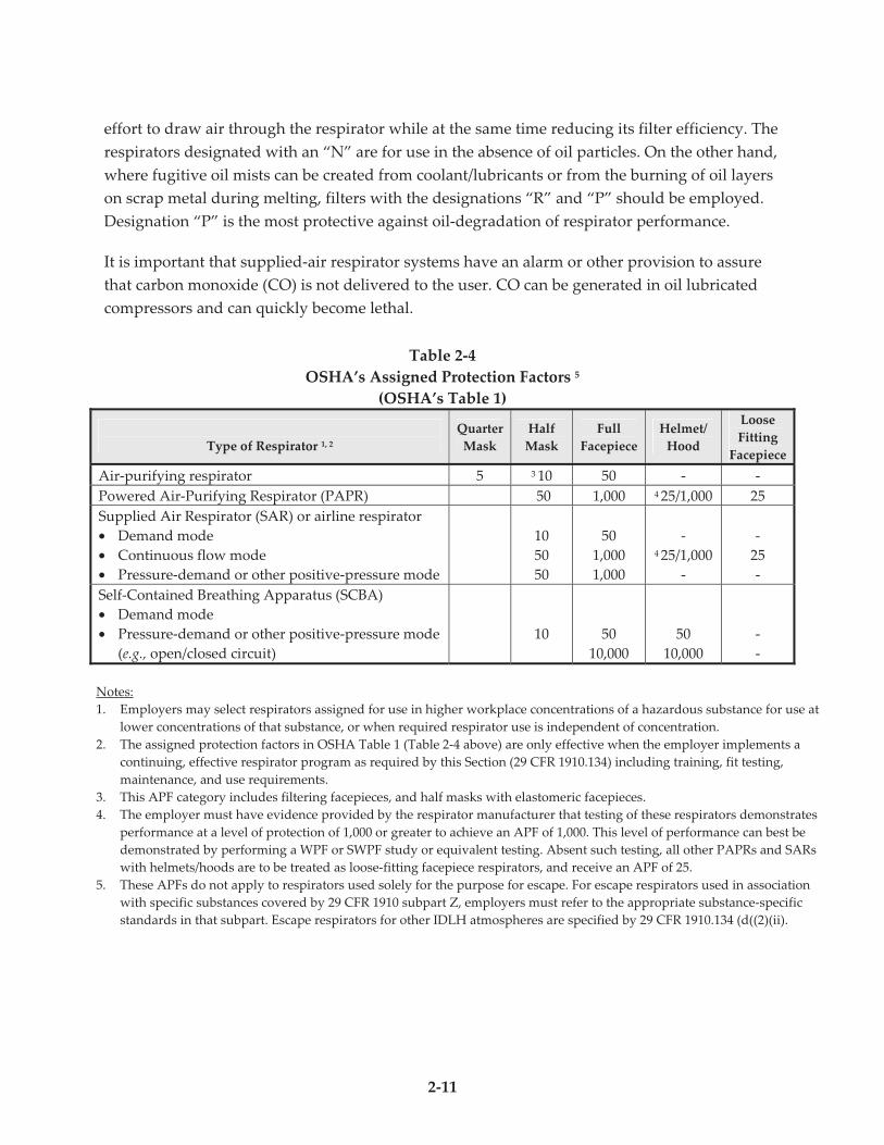
Respirators have Assigned Protection Factors (APFs) that indicate the degree of protection
offered by that class of respirator. OSHA issued new APFs in 2006 and Table 2-4 should be
consulted for details. Disposable half-mask respirators and half-mask elastomeric face piece
respirators have the same APF of 10. This means they can be used in situations where the
exposures are up to 10 times the PEL. PAPRs and supplied-air respirators have APFs of 25 for
loose hoods or helmets, unless the manufacturer can demonstrate that they can actually achieve
a higher APF by testing.
Another number associated with respirators is the filtering efficiency. For silica protection, non-
powered, air-purifying, particulate-filter respirators should carry either a N95 or a N100
designation, indicating that the filter material is efficient enough to remove respirable dust. A
N95 designation means the respirator is capable of removing 95 percent of particles that are 0.3
microns in size.
Beyond filter efficiency, there is another consideration, filter degradation, which must be taken
into account when selecting nonpowered, air-purifying, particulate-filter respirators. Oil
particles can rapidly cause the pore spaces of the filter material to plug, thus increasing the
2-11
effort to draw air through the respirator while at the same time reducing its filter efficiency. The
respirators designated with an “N” are for use in the absence of oil particles. On the other hand,
where fugitive oil mists can be created from coolant/lubricants or from the burning of oil layers
on scrap metal during melting, filters with the designations “R” and “P” should be employed.
Designation “P” is the most protective against oil-degradation of respirator performance.
It is important that supplied-air respirator systems have an alarm or other provision to assure
that carbon monoxide (CO) is not delivered to the user. CO can be generated in oil lubricated
compressors and can quickly become lethal.
Table 2-4
OSHA’s Assigned Protection Factors 5
(OSHA’s Table 1)
Type of Respirator 1, 2
Quarter
Mask
Half
Mask
Full
Facepiece
Helmet/
Hood
Loose
Fitting
Facepiece
Air-purifying respirator 5 3 10 50 - -
Powered Air-Purifying Respirator (PAPR) 50 1,000 4 25/1,000 25
Supplied Air Respirator (SAR) or airline respirator
• Demand mode
• Continuous flow mode
• Pressure-demand or other positive-pressure mode
10
50
50
50
1,000
1,000
- 4 25/1,000
-
-
25
-
Self-Contained Breathing Apparatus (SCBA)
• Demand mode
• Pressure-demand or other positive-pressure mode
(e.g., open/closed circuit)
10
50
10,000
50
10,000
-
-
Notes:
1. Employers may select respirators assigned for use in higher workplace concentrations of a hazardous substance for use at
lower concentrations of that substance, or when required respirator use is independent of concentration.
2. The assigned protection factors in OSHA Table 1 (Table 2-4 above) are only effective when the employer implements a
continuing, effective respirator program as required by this Section (29 CFR 1910.134) including training, fit testing,
maintenance, and use requirements.
3. This APF category includes filtering facepieces, and half masks with elastomeric facepieces.
4. The employer must have evidence provided by the respirator manufacturer that testing of these respirators demonstrates
performance at a level of protection of 1,000 or greater to achieve an APF of 1,000. This level of performance can best be
demonstrated by performing a WPF or SWPF study or equivalent testing. Absent such testing, all other PAPRs and SARs
with helmets/hoods are to be treated as loose-fitting facepiece respirators, and receive an APF of 25.
5. These APFs do not apply to respirators used solely for the purpose for escape. For escape respirators used in association
with specific substances covered by 29 CFR 1910 subpart Z, employers must refer to the appropriate substance-specific
standards in that subpart. Escape respirators for other IDLH atmospheres are specified by 29 CFR 1910.134 (d((2)(ii).
2-12
2.8 Medical Surveillance Programs for Employees Exposed to Silica
The purpose of a medical surveillance program, often called health screening, is to identify
changes in health early enough so that intervention can take place to prevent illness from
occurring. It is important to detect pre-existing conditions that might place the exposed
employee at increased risk, and to establish a baseline for future health monitoring. Physicians
familiar with the health effects of silica should be consulted when establishing and maintaining
a medical surveillance program. Examination of the respiratory system and cardiovascular
system should be stressed.
In the case of silica, various recommendations have been made regarding who should be
screened, what tests should be performed and how often they should be performed. Many
OSHA health standards require medical surveillance when employees are exposed at or above
the Action Level (AL), typically set at one-half of the PEL. There is some consensus about what
should be included in an examination for employees exposed to silica:
! Physical examination, health and work history.
! Chest x-ray which is classified according to the latest ILO (International Labor
Organization) guidelines by NIOSH Certified “B” Readers. These physicians have
demonstrated that they are proficient in classifying chest x-rays for diseases such as
silicosis through examinations administered by NIOSH. There are not many NIOSH
Certified B Readers but it is very important that one be used to read the x-rays to
ensure that early changes are properly identified. NIOSH maintains a list of certified B-
Readers on their website (http://www.cdc.gov/niosh/topics/chestradiography/breader-
list.html) that is searchable by state.
! Pulmonary function testing (PFTs), although some experts feel that routine PFTs are
not useful for early detection of silica related lung disease since most abnormalities
detected are due to conditions not related to work. If PFTs are done, they should be
performed by someone who has demonstrated proficiency in conducting the tests.
! A TB test for workers who show evidence of silicosis and who have not been
previously tested
The frequency of the examinations will vary depending on the advice of the physician
administering the examination. OSHA has recommended in their Special Emphasis Program for
Silica that examinations should be conducted upon hire (baseline), at least every 5 years for
those with less than 20 years of exposure and every 2 years for those with more than 20 years of
exposure to silica. More frequent examinations are needed for employees showing signs of
silicosis. An examination should also be given upon termination of employment. Other groups
such as the American College of Occupational and Environmental Medicine (ACOEM)
2-13
recommend a different schedule although their schedule also varies depending on how long the
employee has been exposed and whether or not there is evidence of disease.
What should be done with employees who exhibit abnormalities consistent with silicosis?
OSHA recommends in their Special Emphasis Program that employees who have a positive
chest x-ray (reading of 1/0 or greater) be placed in a mandatory respiratory protection program
and referred to a physician specializing in lung disease for further follow-up. The affected
employee should also be counseled about silicosis prevention, safe work practices, and smoking
cessation.
As with any occupational medical surveillance program, a close working relationship with the
medical provider needs to be established and employers must understand the ethical and legal
obligations medical professionals must adhere to regarding medical records, information
disclosure and employee counseling.

2-14
3-1
Section 3
How to Identify and Control Sources of
Silica Dust Exposure Robert C. Scholz, P.E., CIH
RMT, Inc., Brookfield, WI
To manage silica dust exposure in foundries effectively, it is necessary to identify and control
significant sources of airborne silica dust. There are many potential sources of silica dust in
foundries which use silica sand for moldmaking and coremaking (Tables 2-2 and 2-3).
Identifying which sources are significant and establishing ways to control exposures from
these sources can be challenging. This section identifies a strategy to meet this challenge.
In Section 2, personal exposure monitoring was described to identify workers at risk of being
over-exposed to respirable silica dust. This method averages the silica exposure concentration
over the entire workshift. Silica exposure concentration can vary over the workshift,
depending on worker involvement with dust-producing processes and the background air
silica concentrations of those parts of the foundry in which the worker spends time. There are
air sampling methods available to evaluate the causes of exposure that relate to the work
operation itself and the causes of exposure that relate to the foundry air environment. In the
field of industrial hygiene, these sampling methods are commonly referred to as”engineering
sampling” methods. This section describes some engineering air sampling methods and goes
on to list the control measures which can address the root causes of silica exposure.
3.1 Real-Time Dust Exposure Monitoring
Current technology permits measuring and recording exposure to respirable particulate
matter (PM) in real-time using available portable instruments. One of the principal benefits
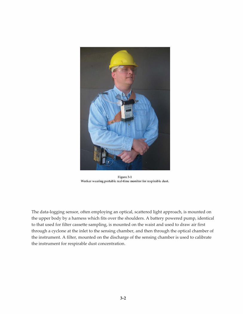
this technique has provided is a growing appreciation for the fact that dusty activities which
occur over short periods can result in significant impacts on overall time-weighted-average
(TWA) exposure. Figure 3-1 shows a setup typical of what was used in Kennedy Valve’s
program to improve the dust exposure protection provided by bench grinding ventilation
(Case History A).
3-2
The data-logging sensor, often employing an optical, scattered light approach, is mounted on
the upper body by a harness which fits over the shoulders. A battery powered pump, identical
to that used for filter cassette sampling, is mounted on the waist and used to draw air first
through a cyclone at the inlet to the sensing chamber, and then through the optical chamber of
the instrument. A filter, mounted on the discharge of the sensing chamber is used to calibrate
the instrument for respirable dust concentration.
3-3
Analyzing the dust calibration filter for silica content can provide the average silica
percentage of the dust concentration measured with this instrument over time. It should be
noted; however, that since silica content of the dust varies continuously, knowing average
silica content of the dust does not allow one to generate a real-time plot of silica concentration
from this data. The method is limited to assessing respirable dust levels.
The data logged by the instrument is subsequently downloaded. A correlation to
real-time activities is provided either by manual note taking with notations of time, or by
simultaneous video recording.
3.2 Respirable Dust Concentration Mapping of the Workplace
Industrial ventilation engineering experience has shown that air contaminants migrate and
concentrate in the workplace environment depending on the locations and emission rates of
fugitive air contaminant sources and on ventilation rates and patterns. In some cases, personal
sampling apparatus has been used to gather “area samples” of the foundry workplace. The
limitation of this method is that a significant number of areas samples are needed to
adequately characterize background air quality. An alternative method is available that can
allow mapping of respirable dust concentration levels everywhere in the foundry. The data
can be gathered using the same real-time analyzer that was prescribed for personal exposure
monitoring in Section 3.1. The method is further described in the AFS publication, “Managing
the Foundry Indoor Air Environment,” Section 8, contact the AFS e-store at:
http://www.afsinc.org/estore . The method is also described in AFS Transaction 01-152, “A
Measurement Method to Pinpoint and Assess High Contaminant Zones within Foundries,”
contact the AFS Library at: http://www.afslibrary.com .
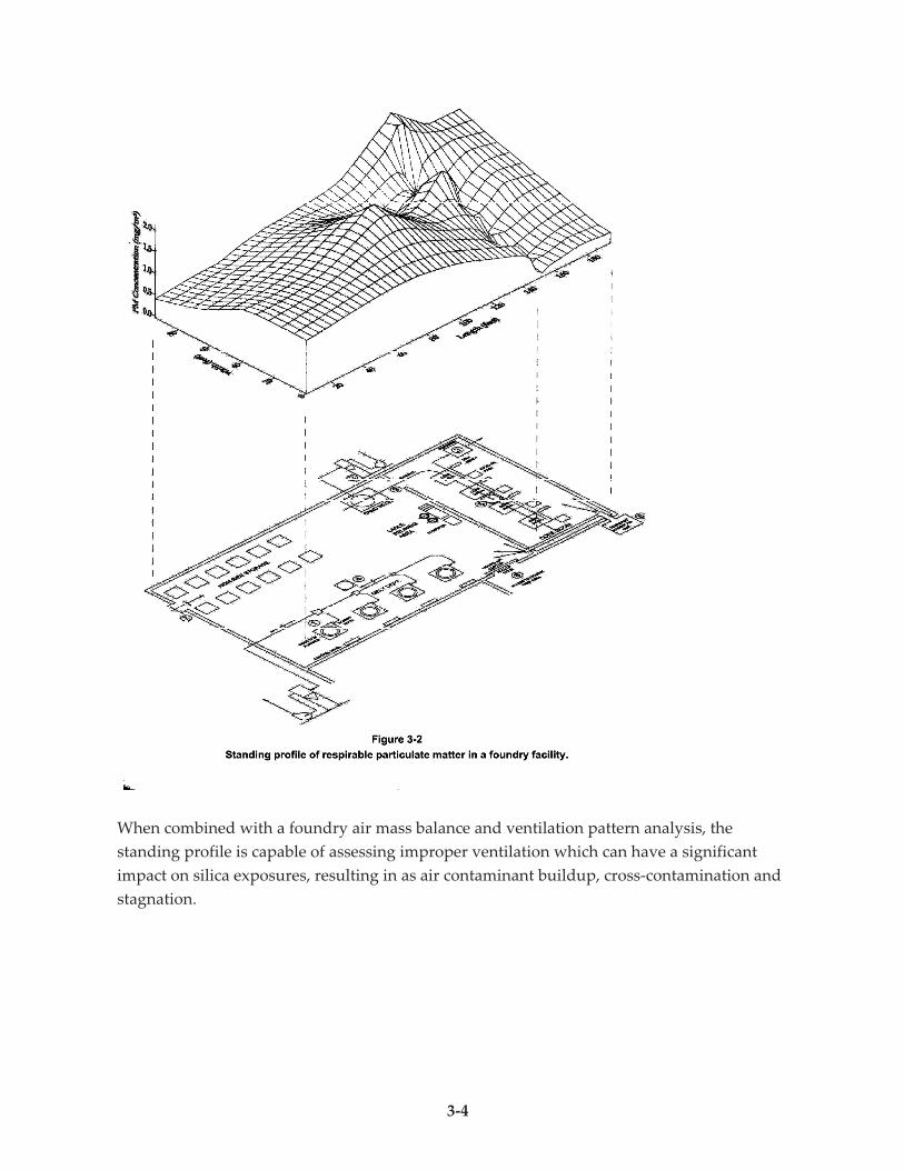
The dust concentration map can be presented as a plan view contour mapping of
concentrations which occur throughout the foundry at breathing zone height. An example of
mapping of respirable dust concentration in a foundry is shown in Figure 3-2. The foundry
layout is shown beneath the contour map. This contour was produced by gathering readings
of respirable PM at a series of points throughout the area of interest or throughout the entire
foundry. For this reason, the method is sometimes called “grid sampling.”
Experience in dust concentration mapping in foundries has demonstrated that these
concentration patterns are quite stable. For this reason, they are sometimes referred to as
“standing profiles.”
3-4
When combined with a foundry air mass balance and ventilation pattern analysis, the
standing profile is capable of assessing improper ventilation which can have a significant
impact on silica exposures, resulting in as air contaminant buildup, cross-contamination and
stagnation.
3-5
3.3 Scope of Exposure Control Methods
There are provisions which can be made in the design, operation, and maintenance of foundry
processes, equipment, and facilities to reduce the silica exposure hazard. Exposure controls
can be generally classified as engineering controls, work practice controls, and administrative
controls.
Engineering controls are the primary method for controlling exposures to respirable silica
dust. Engineering controls focus on:
! Process equipment, material handling, tools, materials, and procedures. Process
control involves maintenance as well as operation.
! Facility, with its layout, work surfaces, traffic routes, and housekeeping provisions.
(The term “facility” as used here includes all of the space in which foundry
operations are conducted, both indoors and out).
! Ventilation systems, including both local and general supply and exhaust systems.
The field of industrial hygiene has traditionally categorized engineering controls for air
contaminant hazards as: substitution, isolation, and ventilation. Substitution is a broad term
used to include techniques for replacement of hazardous materials, processes, or pieces of
equipment with less or nonhazardous ones. Substituting with a low or no silica-containing
material is a prime example of this silica exposure control technique. Isolation of hazards is
done by interposing a barrier between the worker and the hazard. Isolation can involve a
physical barrier, a suitable distance between the worker and the hazard or a time lapse to
provide a safety factor against exposure.
Work practice controls include specific actions taken by workers to minimize the generation
and dispersion of dust into their own breathing zones as well as into the breathing zones of
nearby workers or into the general inplant environment. Some fundamental work practices
are:
! Good housekeeping;
! Appropriate personal hygiene practices;
! Periodic inspection and maintenance of process and engineering control equipment;
! Proper procedures to perform a task;
! Appropriate supervision to assure that proper procedures are followed.
Administrative controls include options such as exposure monitoring, medical surveillance,
education and training. Administrative controls can involve limiting exposure in structuring
work assignments.
3-6
3.4 Exposure Control Focuses on Process and Material Handling
In foundries using silica sand for moldmaking and coremaking, making quality castings
requires close control of sand systems. This close control has a significant impact on the
production and dispersion of silica dust into the foundry environment. Here are some
examples of process areas where good foundry sand management can reduce the potential for
exposure to silica dust.
Green Sand Compaction
Proper compaction is critical to green sand molding. Besides providing the correct mixture of
ingredients, it is also essential to maintain moisture and temperature control. When
temperature of molding sand rises above 120°F, molding sand dries out quickly and loses its
compactability. The amount of moisture required for compaction is sufficient to suppress the
emission of fines from molding sand.
Surface Finish at the Molten Metal Interfaces with Molds and Cores
Mold and core surfaces are intended to minimize metal penetration (e.g., burn-on, burn-in)
which shot blasting cannot effectively remove. Excessive metal penetration results in the need
for dust-producing manual grinding operations.
Maintenance of Seals during Blowing of Sand into Molds and Cores
Seals on pressure blown sand systems are necessary for complete filling of mold and core
boxes. Seal leaks on the other hand, result in dispersion of dust and loss of sand delivery
efficiency.
Shakeout Efficiency
The term “shakeout” as used here includes all mechanical methods such as dump-off
conveyors, vibrating tables, rotary drums, and preblast conveyors which are used to achieve
the separation of the cast metal from mold and core materials prior to handling and processing
the casting and its appendages. Employing shakeout techniques which are effective at
removing adhered sand and cores from castings is critical for several reasons:
! To minimize dust exposure during manual despruing and sorting operations and all
casting finishing operations that follow. These casting finishing processes provide
some of the greatest challenges to the use of local exhaust ventilation to control
worker exposures.
3-7
! To reduce wear and tear on shot blast equipment as well as to confront the challenge
to the dust control provisions of that equipment when excess sand is removed by
blasting equipment.
! To reduce adhered sand and cores on foundry returns, which causes dust issues in
the charge preparation and melting areas, which ultimately creates excess dross and
reduces the life of furnace linings. Furnace relining operations have high silica
exposure potential; extending the life of furnace linings reduces the amount of this
work which is required.
Sand Containment in Material Handling Systems
Of the foundry process variables affecting silica exposure potential listed in Table 2-2, about
one-fourth directly involve material handling of silica-bearing materials and many other items
involve feeding, processing, and discharge of this material. Dust control from silica-bearing
materials is facilitated when these materials are contained and prevented from falling onto
floor surfaces that are traversed by workers and vehicles. Even during material handling and
processing of sand in mechanized systems there is potential for significant dust emissions
from:
• Conveyor belt spillage and spillage at transfer points;
• Return belt shedding of adhered materials;
• Leaks in pneumatic transfer lines;
• Vibratory dispersal of dust from oscillating conveyors.
Material handling spillage can occur in relatively inaccessible or confined conditions,
necessitating manual cleanup with its dust exposure hazards.
3.5 Ventilation of Silica Dust Sources
Silica dust that is controlled at the source through local ventilation can be prevented from
entering either the breathing zones of workers located close to those sources or the general
inplant air environment.
Local exhaust ventilation to isolate and capture the dust sources is a method that is generally
understood. Local supply air techniques which are equally essential for effective dust
exposure control are not as well understood. A relatively new technique for supply air to fixed
work stations called “supply air island” uses a low velocity distribution of air from a close
overhead position either directly above or to the side and angled downward at the worker.
This supply air envelops the worker, yet it does not interfere with exhaust hood capture and it
reduces the need for disruptive portable, circulating fans. Wescast Industries, Inc. in Case
3-8
History B describes how they have successfully employed the supply air island approach to
protect workers from silica exposure and are now continuing to refine it.
Integrated ventilation design involving area-wide balanced supply and exhaust is a strategy
which Acme Foundry has advanced in its design of a ferrous casting finishing facility (Case
History C).
Information on how to design foundry ventilation is available in a number of sources, among
them:
! “Industrial Ventilation Manual of Recommended Practice” of the American
Conference of Governmental Industrial Hygienists (ACGIH). This manual,
updated every three years, is available at:
American Conference of Governmental Industrial Hygienists
1330 Kemper Meadow Drive
Cincinnati, Ohio 45240-1634
513-742-2020
www.acgih.org
! “Managing the Foundry Indoor Air Environment” written by the 10Q Safety and
Health Committee of AFS. Sections 5 through 7 of this manual include detailed
discussions concerning the use of ventilation to control dust emissions in
sandcasting operations. This manual is available at:
American Foundry Society
1695 N. Penny Lane
Schaumburg, IL, 60173
800-537-4237
www.afsinc.org/estore
3.6 Silica Exposure Control Program Strategy
The ideal situation for gathering exposure samples and assessing the need to improve
exposure control is for all of the silica control measures used at a foundry to be in place and
functioning as designed during exposure monitoring. Sampling under this condition is termed
“baseline exposure monitoring.” Where this occurs, exposure sampling in turn is able to
define the capability of the exposure controls. If such sampling indicates an overexposure
condition, exposure control improvements are thereby shown to be warranted. If, on the other
hand, not all controls are functioning properly at the time of the sampling, a condition is
created which does not define control capability and is very difficult to interpret.
3-9
Figure 3-3 presents a flow chart associated with use of the baseline exposure monitoring
approach. On the bottom of the figure, the logic is presented in a flowchart. On the top of the
figure, the procedure is presented as a series of steps to be taken.
As can be seen in Step 1, the baseline conditions include all facets of exposure control. Continuous
operation at baseline conditions is sought, not focus on “doing it right” during exposure testing.
Checklists are useful to confirm that baseline conditions are being met continuously. In some
foundries, the operation of ventilation devices is decentralized and it may not be obvious that all of
the needed ventilation devices, including powered makeup air devices, are operating as planned.
Some foundries conduct regular, periodic ventilation assessment and when they follow-up on
ventilation system issues identified by these evaluations, these foundries achieve continuous
compliance with baseline conditions. The AFS Manual, “Managing the Foundry Indoor Air
Environment” presents a strategy in Section 9 for maintaining ventilation system performance.
Step 2 allows for correction of issues prior to sampling. In certain cases, it may be necessary to
continue to Step 3 without having resolved all issues when the time period to resolve an issue
would unreasonably postpone the assessment.
The need to thoroughly monitor the exposure sampling conducted in Step 3 which was
discussed in Subsection 2.5 cannot be overemphasized.
If overexposures are identified in Step 4, further effort is required in Steps 5 and 6 to evaluate
and resolve exposure sources. Foundry experience has shown that it is cost effective to
demonstrate potential silica exposure control improvements on a prototype basis before
instituting them on a permanent basis. Case History A by Kennedy Valve describes a
controlled development program undertaken in an isolated setting in a foundry to optimize
the control of grinding dust prior to implementing the new technique in the entire grinding
operation. Case History D by Grede Foundry describes a program which was implemented to
upgrade an existing degating and sorting station, using exposure monitoring to assess and
redirect the effort.
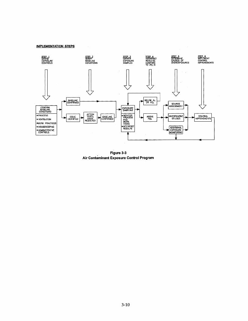
3-10
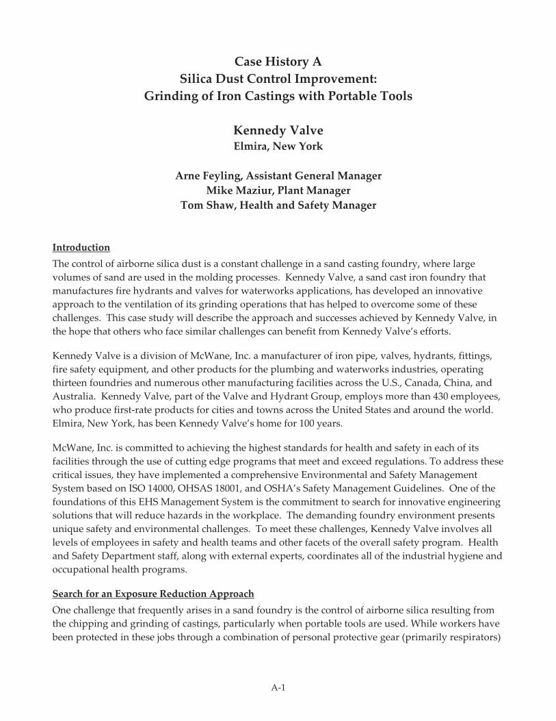
A-1
Case History A
Silica Dust Control Improvement:
Grinding of Iron Castings with Portable Tools
Kennedy Valve Elmira, New York
Arne Feyling, Assistant General Manager
Mike Maziur, Plant Manager
Tom Shaw, Health and Safety Manager
Introduction
The control of airborne silica dust is a constant challenge in a sand casting foundry, where large
volumes of sand are used in the molding processes. Kennedy Valve, a sand cast iron foundry that
manufactures fire hydrants and valves for waterworks applications, has developed an innovative
approach to the ventilation of its grinding operations that has helped to overcome some of these
challenges. This case study will describe the approach and successes achieved by Kennedy Valve, in
the hope that others who face similar challenges can benefit from Kennedy Valve’s efforts.
Kennedy Valve is a division of McWane, Inc. a manufacturer of iron pipe, valves, hydrants, fittings,
fire safety equipment, and other products for the plumbing and waterworks industries, operating
thirteen foundries and numerous other manufacturing facilities across the U.S., Canada, China, and
Australia. Kennedy Valve, part of the Valve and Hydrant Group, employs more than 430 employees,
who produce first-rate products for cities and towns across the United States and around the world.
Elmira, New York, has been Kennedy Valve’s home for 100 years.
McWane, Inc. is committed to achieving the highest standards for health and safety in each of its
facilities through the use of cutting edge programs that meet and exceed regulations. To address these
critical issues, they have implemented a comprehensive Environmental and Safety Management
System based on ISO 14000, OHSAS 18001, and OSHA’s Safety Management Guidelines. One of the
foundations of this EHS Management System is the commitment to search for innovative engineering
solutions that will reduce hazards in the workplace. The demanding foundry environment presents
unique safety and environmental challenges. To meet these challenges, Kennedy Valve involves all
levels of employees in safety and health teams and other facets of the overall safety program. Health
and Safety Department staff, along with external experts, coordinates all of the industrial hygiene and
occupational health programs.
Search for an Exposure Reduction Approach
One challenge that frequently arises in a sand foundry is the control of airborne silica resulting from
the chipping and grinding of castings, particularly when portable tools are used. While workers have
been protected in these jobs through a combination of personal protective gear (primarily respirators)
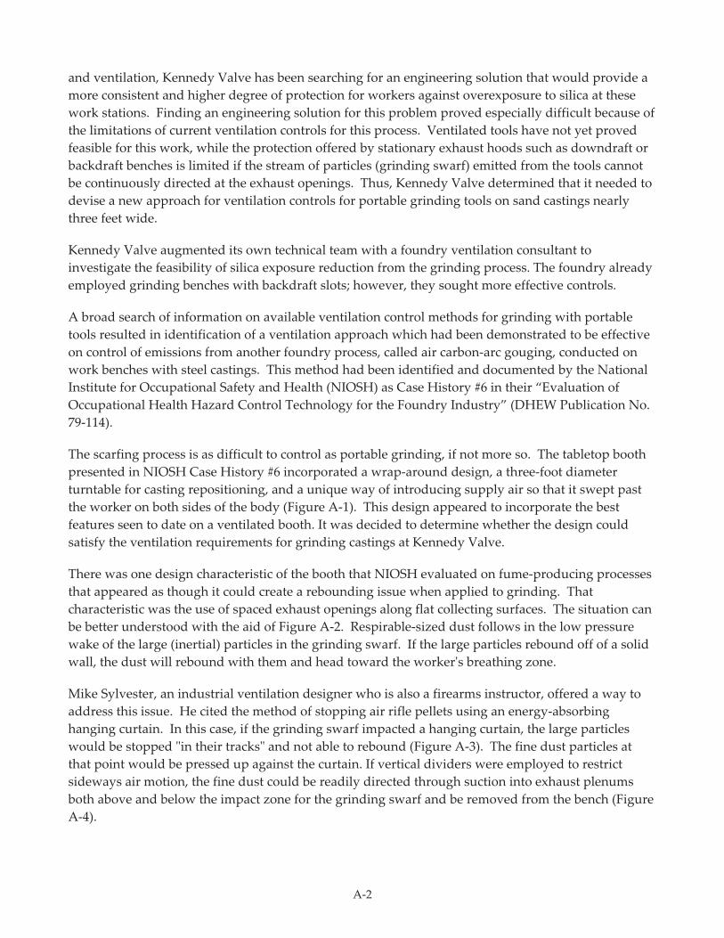
A-2
and ventilation, Kennedy Valve has been searching for an engineering solution that would provide a
more consistent and higher degree of protection for workers against overexposure to silica at these
work stations. Finding an engineering solution for this problem proved especially difficult because of
the limitations of current ventilation controls for this process. Ventilated tools have not yet proved
feasible for this work, while the protection offered by stationary exhaust hoods such as downdraft or
backdraft benches is limited if the stream of particles (grinding swarf) emitted from the tools cannot
be continuously directed at the exhaust openings. Thus, Kennedy Valve determined that it needed to
devise a new approach for ventilation controls for portable grinding tools on sand castings nearly
three feet wide.
Kennedy Valve augmented its own technical team with a foundry ventilation consultant to
investigate the feasibility of silica exposure reduction from the grinding process. The foundry already
employed grinding benches with backdraft slots; however, they sought more effective controls.
A broad search of information on available ventilation control methods for grinding with portable
tools resulted in identification of a ventilation approach which had been demonstrated to be effective
on control of emissions from another foundry process, called air carbon-arc gouging, conducted on
work benches with steel castings. This method had been identified and documented by the National
Institute for Occupational Safety and Health (NIOSH) as Case History #6 in their “Evaluation of
Occupational Health Hazard Control Technology for the Foundry Industry” (DHEW Publication No.
79-114).
The scarfing process is as difficult to control as portable grinding, if not more so. The tabletop booth
presented in NIOSH Case History #6 incorporated a wrap-around design, a three-foot diameter
turntable for casting repositioning, and a unique way of introducing supply air so that it swept past
the worker on both sides of the body (Figure A-1). This design appeared to incorporate the best
features seen to date on a ventilated booth. It was decided to determine whether the design could
satisfy the ventilation requirements for grinding castings at Kennedy Valve.
There was one design characteristic of the booth that NIOSH evaluated on fume-producing processes
that appeared as though it could create a rebounding issue when applied to grinding. That
characteristic was the use of spaced exhaust openings along flat collecting surfaces. The situation can
be better understood with the aid of Figure A-2. Respirable-sized dust follows in the low pressure
wake of the large (inertial) particles in the grinding swarf. If the large particles rebound off of a solid
wall, the dust will rebound with them and head toward the worker's breathing zone.
Mike Sylvester, an industrial ventilation designer who is also a firearms instructor, offered a way to
address this issue. He cited the method of stopping air rifle pellets using an energy-absorbing
hanging curtain. In this case, if the grinding swarf impacted a hanging curtain, the large particles
would be stopped "in their tracks" and not able to rebound (Figure A-3). The fine dust particles at
that point would be pressed up against the curtain. If vertical dividers were employed to restrict
sideways air motion, the fine dust could be readily directed through suction into exhaust plenums
both above and below the impact zone for the grinding swarf and be removed from the bench (Figure
A-4).
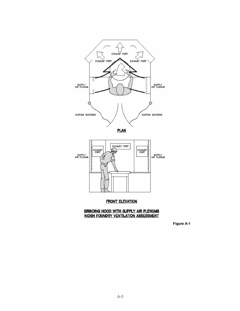
A-3
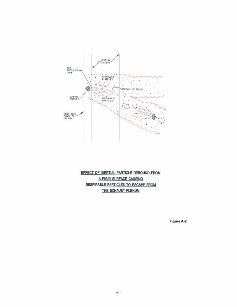
A-4
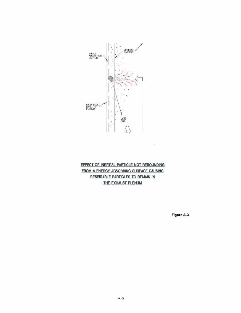
A-5
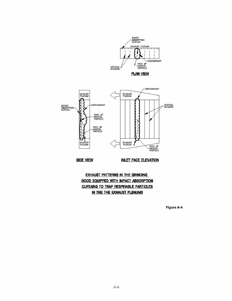
A-6
A-7
Demonstration of Dust Control Effectiveness
Figure A-5 shows the method in the form considered suitable for the demonstration phase at
Kennedy Valve. A prototype grinding booth was constructed for the demonstration and
subsequently tested in an isolated part of the facility, where the potential for cross-contamination
from any other silica-producing process was eliminated. Figure A-6 shows the grinding booth
following the prototype demonstration, in its current form for production grinding. Castings are
moved on and off of the work surface by overhead hoist. After the castings are set down on the
workbench, they may be rotated via a turntable for better access to surfaces to be ground, to assist the
ergonomic aspects of the work, and to allow the grinding swarf to be directed as far as possible into
the capture zones. The worker can initiate the turntable using a “bump” switch which does not
require hand use and, thus, does not slow down the grinding operation.
In the process of evaluating the ventilated grinding booth, respirable dust was measured in the
breathing zone of the grinding operator and in the general background air next to the grinding booth.
For this purpose, two real-time particle sensors (Thermo Electron Corporation Model PDR 1200
dataRAM) were used. Each sampling inlet was fitted with a cyclone to remove the non-respirable
portion of dust. These instruments simultaneously logged respirable dust during grinding operations
that were also video recorded. The particle sensor data was subsequently downloaded to a computer
and graphed.
A battery-powered (SKC) pump drew air at a regulated flow rate through each instrument to produce
an active sample. The pumps were calibrated before and after each measurement session using a
Mini-Buck M-30 primary standard calibrator.
Since the particle sensors did not provide a real-time measure of silica in the dust, it was used to
evaluate general dust control from the process. Follow-up testing would ultimately be necessary to
determine the time-weighted-average (TWA) of respirable silica dust throughout a workshift in
which both respirable dust levels and silica content of that dust were measured and averaged.
The first testing was done on a single type of casting (i.e., large fitting with 4-inch flanges) selected to
eliminate variability of the work in the initial assessment. Figure A-7 shows personal worker
exposure to respirable dust during the grinding of multiple castings over a 35-minute duration.
Multiple tool positions were used as the operator removed material using a portable grinder from all
internal and external surfaces around the casting. The resultant data profile consisted of a relatively
level baseline exposure with a number of spikes. The time-weighted average throughout this
grinding session was 0.455 mg/m3, a value which was relatively independent of the rapidly decaying
data spikes (i.e., the exposure associated with the spikes did not measurably affect the average dust
exposure). From a visual standpoint, the only obvious exposure was associated with the manner in
which dust was emitted from the inside of the casting in a “chimney effect” during internal grinding.
This dust was discharged very close to the breathing zone before it was withdrawn by the push of the
supply air and the pull of the hood exhaust. The dust produced by one particular task was directed
in such a way that the exhaust hood could not directly capture it.
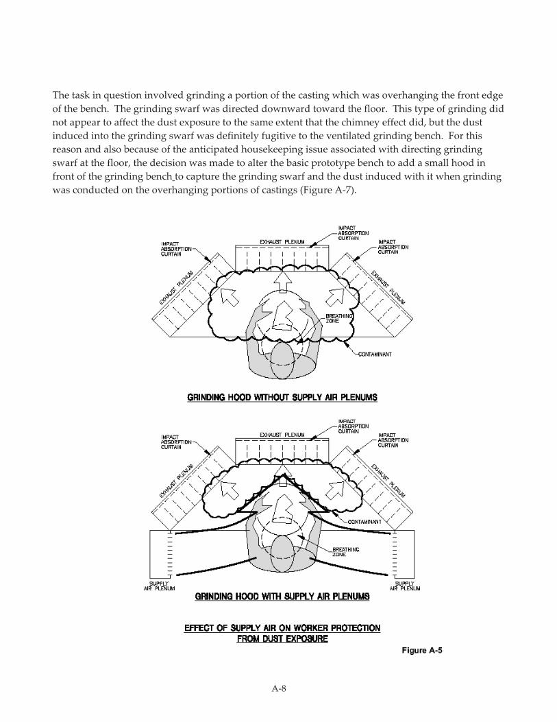
A-8
The task in question involved grinding a portion of the casting which was overhanging the front edge
of the bench. The grinding swarf was directed downward toward the floor. This type of grinding did
not appear to affect the dust exposure to the same extent that the chimney effect did, but the dust
induced into the grinding swarf was definitely fugitive to the ventilated grinding bench. For this
reason and also because of the anticipated housekeeping issue associated with directing grinding
swarf at the floor, the decision was made to alter the basic prototype bench to add a small hood in
front of the grinding bench to capture the grinding swarf and the dust induced with it when grinding
was conducted on the overhanging portions of castings (Figure A-7).
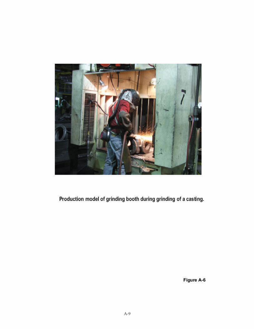
A-9
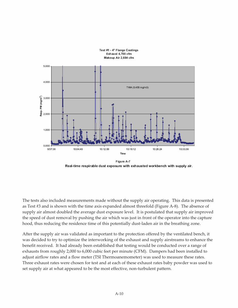
A-10
The tests also included measurements made without the supply air operating. This data is presented
as Test #3 and is shown with the time axis expanded almost threefold (Figure A-8). The absence of
supply air almost doubled the average dust exposure level. It is postulated that supply air improved
the speed of dust removal by pushing the air which was just in front of the operator into the capture
hood, thus reducing the residence time of this potentially dust-laden air in the breathing zone.
After the supply air was validated as important to the protection offered by the ventilated bench, it
was decided to try to optimize the interworking of the exhaust and supply airstreams to enhance the
benefit received. It had already been established that testing would be conducted over a range of
exhausts from roughly 2,000 to 6,000 cubic feet per minute (CFM). Dampers had been installed to
adjust airflow rates and a flow meter (TSI Thermoanemometer) was used to measure these rates.
Three exhaust rates were chosen for test and at each of these exhaust rates baby powder was used to
set supply air at what appeared to be the most effective, non-turbulent pattern.
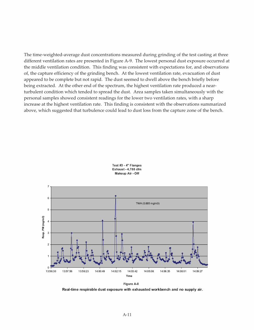
A-11
The time-weighted-average dust concentrations measured during grinding of the test casting at three
different ventilation rates are presented in Figure A-9. The lowest personal dust exposure occurred at
the middle ventilation condition. This finding was consistent with expectations for, and observations
of, the capture efficiency of the grinding bench. At the lowest ventilation rate, evacuation of dust
appeared to be complete but not rapid. The dust seemed to dwell above the bench briefly before
being extracted. At the other end of the spectrum, the highest ventilation rate produced a near-
turbulent condition which tended to spread the dust. Area samples taken simultaneously with the
personal samples showed consistent readings for the lower two ventilation rates, with a sharp
increase at the highest ventilation rate. This finding is consistent with the observations summarized
above, which suggested that turbulence could lead to dust loss from the capture zone of the bench.
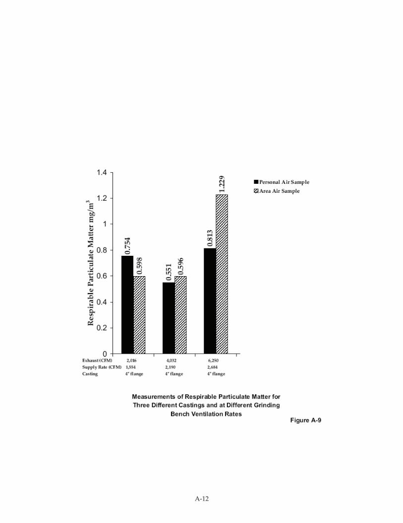
A-12
A-13
Full Scale Operations
After successful completion of the prototype test program, fifteen production booths were
constructed and installed in the renovated finishing area. These benches have consistently controlled
silica exposures during grinding to below OSHA’s Permissible Exposure Level (PEL) for Kennedy
Valve’s grinding needs when operating at exhaust rates down to 3,000 CFM and supply airflow rates
at half of that flow rate. The supply air is provided by a tempered (i.e., heated in winter) makeup air
unit with proportional heater control for steady temperature conditions.
The particles which are “stilled” through contact with the enclosure walls readily fall out into
collection areas in the workbench. This feature has reduced the loading of abrasive particles on the
filter media in the baghouse. Prototype demonstration is recommended for incorporating an
approach such as this into different foundry settings. The expected effectiveness would be dependent
on a number of variables, key among them:
! Extent of sand burn-in/burn-on on the castings.
! Effectiveness of shot blasting in removing sand material from surfaces.
! Amount of grinding performed on a casting.
! Proportion of grinding internal to the casting.
! Ability to perform all grinding on top of the workbench.
Conclusion
Kennedy Valve workers performing this grinding have long been protected via controls like a
respirator program. Only this past year, through the team effort of internal and external resources,
has the use of engineering controls been able to reduce worker exposures to levels consistently below
the current OSHA PEL for silica. The worker in Figure A-6 voluntarily continues to wear the air-
supplied helmet. Workers appreciate the eye and face protection and the stream of air circulating
around the head. Spikes in exposure are not impossible with any local ventilation method applied to
manual processes; the air supplied helmet provides a safety factor against these spikes. Although not
easy, we are closer to our goal of state-of-the-art processes, including worker protection, for cleaning a
variety of castings.

A-14
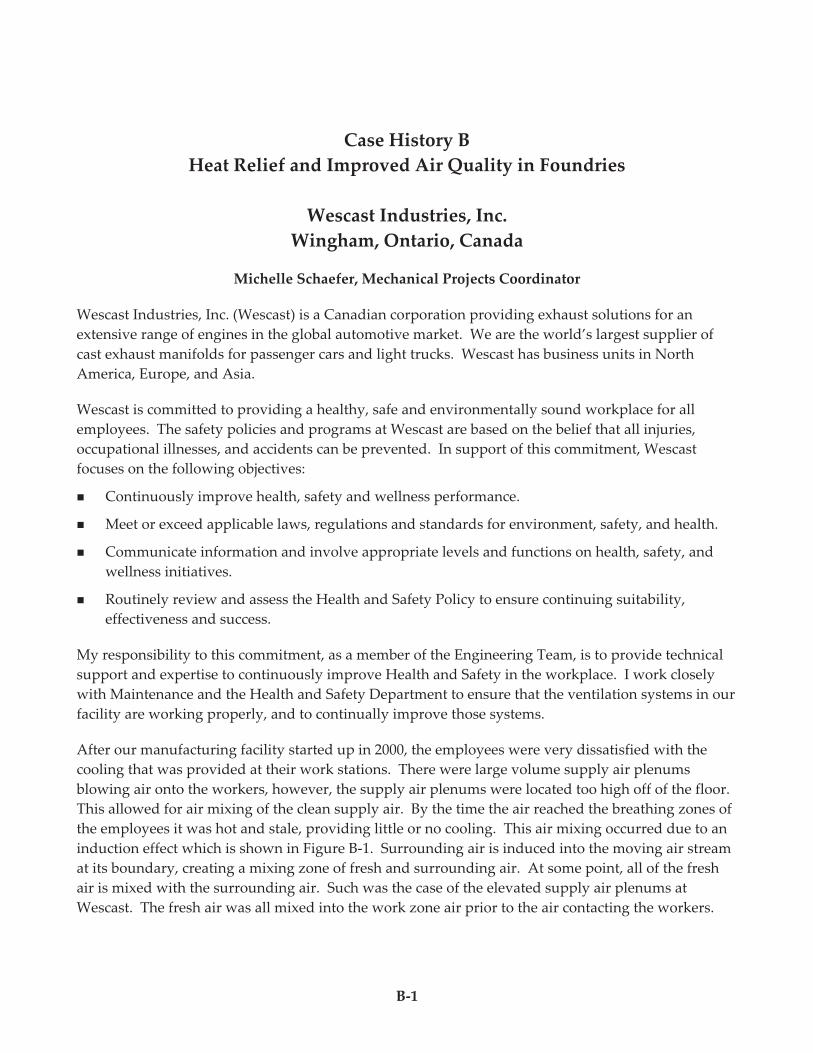
B-1
Case History B
Heat Relief and Improved Air Quality in Foundries
Wescast Industries, Inc.
Wingham, Ontario, Canada
Michelle Schaefer, Mechanical Projects Coordinator
Wescast Industries, Inc. (Wescast) is a Canadian corporation providing exhaust solutions for an
extensive range of engines in the global automotive market. We are the world’s largest supplier of
cast exhaust manifolds for passenger cars and light trucks. Wescast has business units in North
America, Europe, and Asia.
Wescast is committed to providing a healthy, safe and environmentally sound workplace for all
employees. The safety policies and programs at Wescast are based on the belief that all injuries,
occupational illnesses, and accidents can be prevented. In support of this commitment, Wescast
focuses on the following objectives:
! Continuously improve health, safety and wellness performance.
! Meet or exceed applicable laws, regulations and standards for environment, safety, and health.
! Communicate information and involve appropriate levels and functions on health, safety, and
wellness initiatives.
! Routinely review and assess the Health and Safety Policy to ensure continuing suitability,
effectiveness and success.
My responsibility to this commitment, as a member of the Engineering Team, is to provide technical
support and expertise to continuously improve Health and Safety in the workplace. I work closely
with Maintenance and the Health and Safety Department to ensure that the ventilation systems in our
facility are working properly, and to continually improve those systems.
After our manufacturing facility started up in 2000, the employees were very dissatisfied with the
cooling that was provided at their work stations. There were large volume supply air plenums
blowing air onto the workers, however, the supply air plenums were located too high off of the floor.
This allowed for air mixing of the clean supply air. By the time the air reached the breathing zones of
the employees it was hot and stale, providing little or no cooling. This air mixing occurred due to an
induction effect which is shown in Figure B-1. Surrounding air is induced into the moving air stream
at its boundary, creating a mixing zone of fresh and surrounding air. At some point, all of the fresh
air is mixed with the surrounding air. Such was the case of the elevated supply air plenums at
Wescast. The fresh air was all mixed into the work zone air prior to the air contacting the workers.
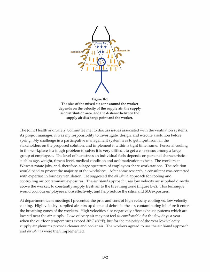
B-2
The Joint Health and Safety Committee met to discuss issues associated with the ventilation systems.
As project manager, it was my responsibility to investigate, design, and execute a solution before
spring. My challenge in a participative management system was to get input from all the
stakeholders on the proposed solution, and implement it within a tight time frame. Personal cooling
in the workplace is a tough problem to solve; it is very difficult to get a consensus among a large
group of employees. The level of heat stress an individual feels depends on personal characteristics
such as age, weight, fitness level, medical condition and acclimatization to heat. The workers at
Wescast rotate jobs, and, therefore, a large spectrum of employees share workstations. The solution
would need to protect the majority of the workforce. After some research, a consultant was contacted
with expertise in foundry ventilation. He suggested the air island approach for cooling and
controlling air contaminant exposures. The air island approach uses low velocity air supplied directly
above the worker, to constantly supply fresh air to the breathing zone (Figure B-2). This technique
would cool our employees more effectively, and help reduce the silica and SO2 exposures.
At department team meetings I presented the pros and cons of high velocity cooling vs. low velocity
cooling. High velocity supplied air stirs up dust and debris in the air, contaminating it before it enters
the breathing zones of the workers. High velocities also negatively affect exhaust systems which are
located near the air supply. Low velocity air may not feel as comfortable for the few days a year
when the outdoor temperatures exceed 30°C (86°F), but for the majority of the year low velocity
supply air plenums provide cleaner and cooler air. The workers agreed to use the air island approach
and air islands were then implemented.
Figure B-1
The size of the mixed air zone around the worker
depends on the velocity of the supply air, the supply
air distribution area, and the distance between the
supply air discharge point and the worker.
Fresh Air
Induced Air
Air Mixing Air Mixing
Induced Air
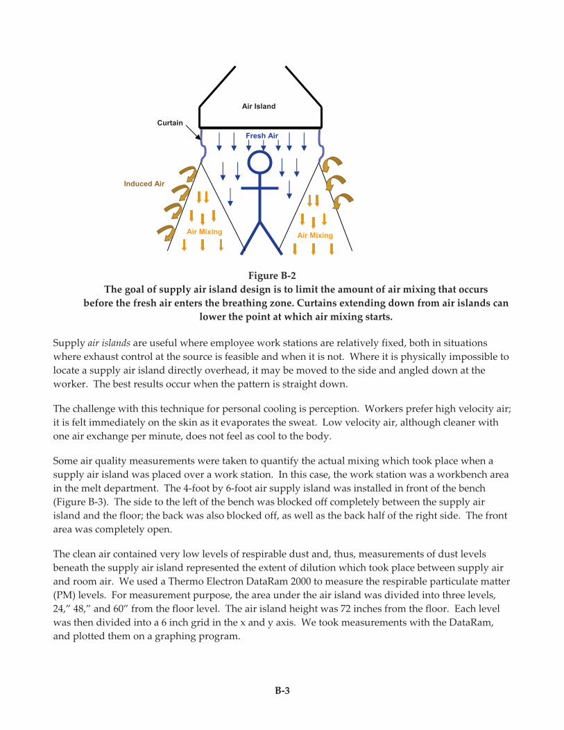
B-3
Figure B-2
The goal of supply air island design is to limit the amount of air mixing that occurs
before the fresh air enters the breathing zone. Curtains extending down from air islands can
lower the point at which air mixing starts.
Supply air islands are useful where employee work stations are relatively fixed, both in situations
where exhaust control at the source is feasible and when it is not. Where it is physically impossible to
locate a supply air island directly overhead, it may be moved to the side and angled down at the
worker. The best results occur when the pattern is straight down.
The challenge with this technique for personal cooling is perception. Workers prefer high velocity air;
it is felt immediately on the skin as it evaporates the sweat. Low velocity air, although cleaner with
one air exchange per minute, does not feel as cool to the body.
Some air quality measurements were taken to quantify the actual mixing which took place when a
supply air island was placed over a work station. In this case, the work station was a workbench area
in the melt department. The 4-foot by 6-foot air supply island was installed in front of the bench
(Figure B-3). The side to the left of the bench was blocked off completely between the supply air
island and the floor; the back was also blocked off, as well as the back half of the right side. The front
area was completely open.
The clean air contained very low levels of respirable dust and, thus, measurements of dust levels
beneath the supply air island represented the extent of dilution which took place between supply air
and room air. We used a Thermo Electron DataRam 2000 to measure the respirable particulate matter
(PM) levels. For measurement purpose, the area under the air island was divided into three levels,
24,” 48,” and 60” from the floor level. The air island height was 72 inches from the floor. Each level
was then divided into a 6 inch grid in the x and y axis. We took measurements with the DataRam,
and plotted them on a graphing program.
Induced Air
Air Mixing
Curtain
Fresh Air
Air Mixing
Air Island
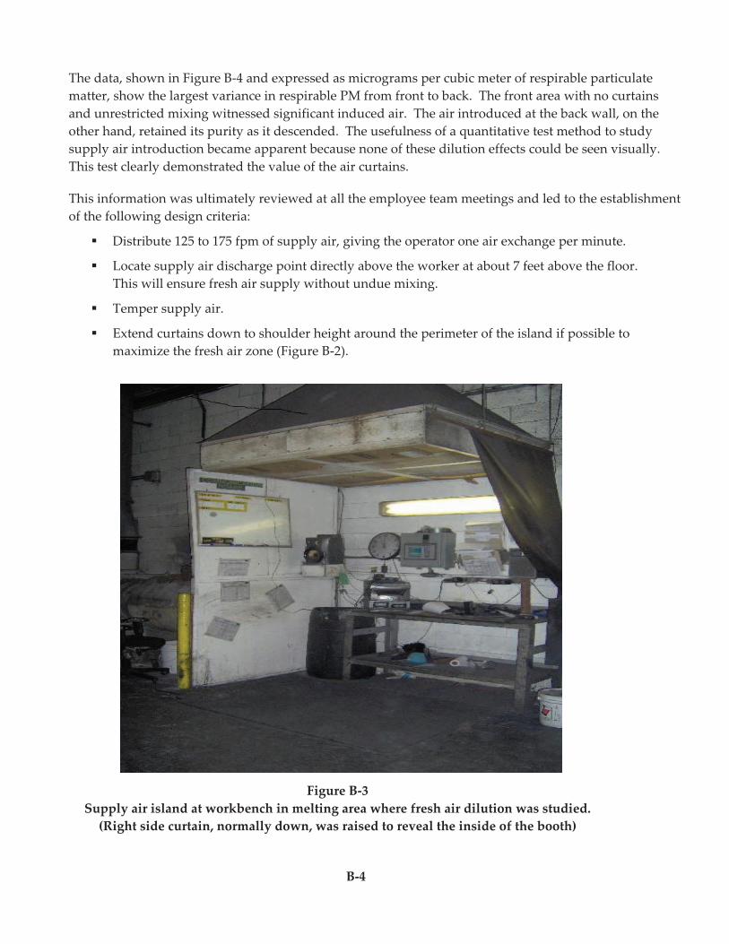
B-5
The data, shown in Figure B-4 and expressed as micrograms per cubic meter of respirable particulate
matter, show the largest variance in respirable PM from front to back. The front area with no curtains
and unrestricted mixing witnessed significant induced air. The air introduced at the back wall, on the
other hand, retained its purity as it descended. The usefulness of a quantitative test method to study
supply air introduction became apparent because none of these dilution effects could be seen visually.
This test clearly demonstrated the value of the air curtains.
This information was ultimately reviewed at all the employee team meetings and led to the establishment
of the following design criteria:
" Distribute 125 to 175 fpm of supply air, giving the operator one air exchange per minute.
" Locate supply air discharge point directly above the worker at about 7 feet above the floor.
This will ensure fresh air supply without undue mixing.
" Temper supply air.
" Extend curtains down to shoulder height around the perimeter of the island if possible to
maximize the fresh air zone (Figure B-2).
Figure B-3
Supply air island at workbench in melting area where fresh air dilution was studied.
(Right side curtain, normally down, was raised to reveal the inside of the booth)
B-4
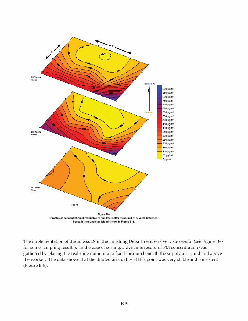
B-5
The implementation of the air islands in the Finishing Department was very successful (see Figure B-5
for some sampling results). In the case of sorting, a dynamic record of PM concentration was
gathered by placing the real-time monitor at a fixed location beneath the supply air island and above
the worker. The data shows that the diluted air quality at this point was very stable and consistent
(Figure B-5).
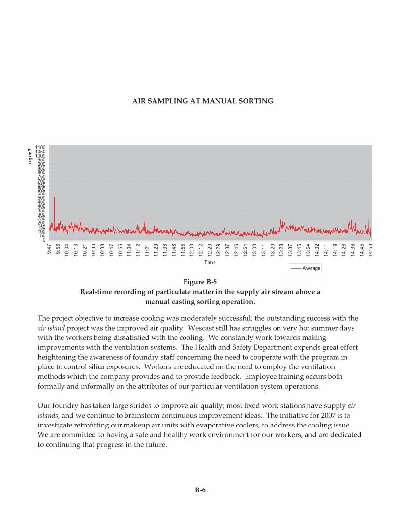
B-6
Figure B-5
Real-time recording of particulate matter in the supply air stream above a
manual casting sorting operation.
The project objective to increase cooling was moderately successful; the outstanding success with the
air island project was the improved air quality. Wescast still has struggles on very hot summer days
with the workers being dissatisfied with the cooling. We constantly work towards making
improvements with the ventilation systems. The Health and Safety Department expends great effort
heightening the awareness of foundry staff concerning the need to cooperate with the program in
place to control silica exposures. Workers are educated on the need to employ the ventilation
methods which the company provides and to provide feedback. Employee training occurs both
formally and informally on the attributes of our particular ventilation system operations.
Our foundry has taken large strides to improve air quality; most fixed work stations have supply air
islands, and we continue to brainstorm continuous improvement ideas. The initiative for 2007 is to
investigate retrofitting our makeup air units with evaporative coolers, to address the cooling issue.
We are committed to having a safe and healthy work environment for our workers, and are dedicated
to continuing that progress in the future.
AIR SAMPLING AT SORT
050
100150200250300350400450500550600650700750800850900950
100010501100115012001250130013501400145015001550160016501700175018001850190019502000
9:4
7
9:5
6
10
:04
10
:13
10
:21
10
:30
10
:38
10
:47
10
:55
11
:04
11
:12
11
:21
11
:29
11
:38
11
:46
11
:55
12
:03
12
:12
12
:20
12
:29
12
:37
12
:46
12
:54
13
:03
13
:11
13
:20
13
:28
13
:37
13
:45
13
:54
14
:02
14
:11
14
:19
14
:28
14
:36
14
:45
14
:53
Time
ug
/m3
Average
Wescast Target Limit
AIR SAMPLING AT MANUAL SORTING
C-1
Case History C
Clearing the Air at Acme Foundry
Integrated Engineering Design of a New Casting Cleaning and Finishing Facility
Acme Foundry, Inc. Coffeyville, Kansas
Don Pusa, Vice President, Engineering
Mark McCullough, Maintenance Supervisor
Acme Foundry, Inc. is located in Coffeyville, Kansas, and produces 19,000 tons/year of gray iron
castings, primarily for the hydraulic valve industry. The foundry has recently planned and
implemented an expansion of its cleaning and finishing area to meet the increasing casting demand.
From the inception of this project, Acme Foundry committed itself to creating a processing facility
that would be a safe, productive, and desirable workplace. Accordingly, engineering was
coordinated so that appropriate consideration was given to, among other things, material flow,
ergonomics, silica dust exposure, stack emissions, noise, climate control, and lighting. What has
resulted from this integrated engineering program is a production facility that meets company goals
and satisfies the needs of customers and the community-at-large. This article is intended to
summarize the program, highlighting some of its features and test results.
Engineering Effort
The engineering effort was supervised by Don Pusa and was supported by plant engineering and
maintenance staff. Outside consultants were employed as needed. A team was thus formed which
assured the desired project integration by deliberating all engineering issues face-to-face to achieve
consensus on the design prior to any construction commitments by the foundry. After design
concepts were finalized, plans and specifications for construction were drawn up and used to solicit
competitive bids.
Cleaning and Finishing Processes
The cleaning and finishing department was earmarked for expansion prior to undertaking a planned
molding department renovation and expansion. From a casting processing standpoint, the expansion
of cleaning and finishing began downstream of the desprueing and shot blasting operations. After
castings are blasted, they are now segregated by size as they are transported into cleaning and
finishing. Large castings (50 to 300 pounds) move along roller conveyors to casting grinding booths,
where they are hoisted onto ventilated workbenches (Figure C-1).
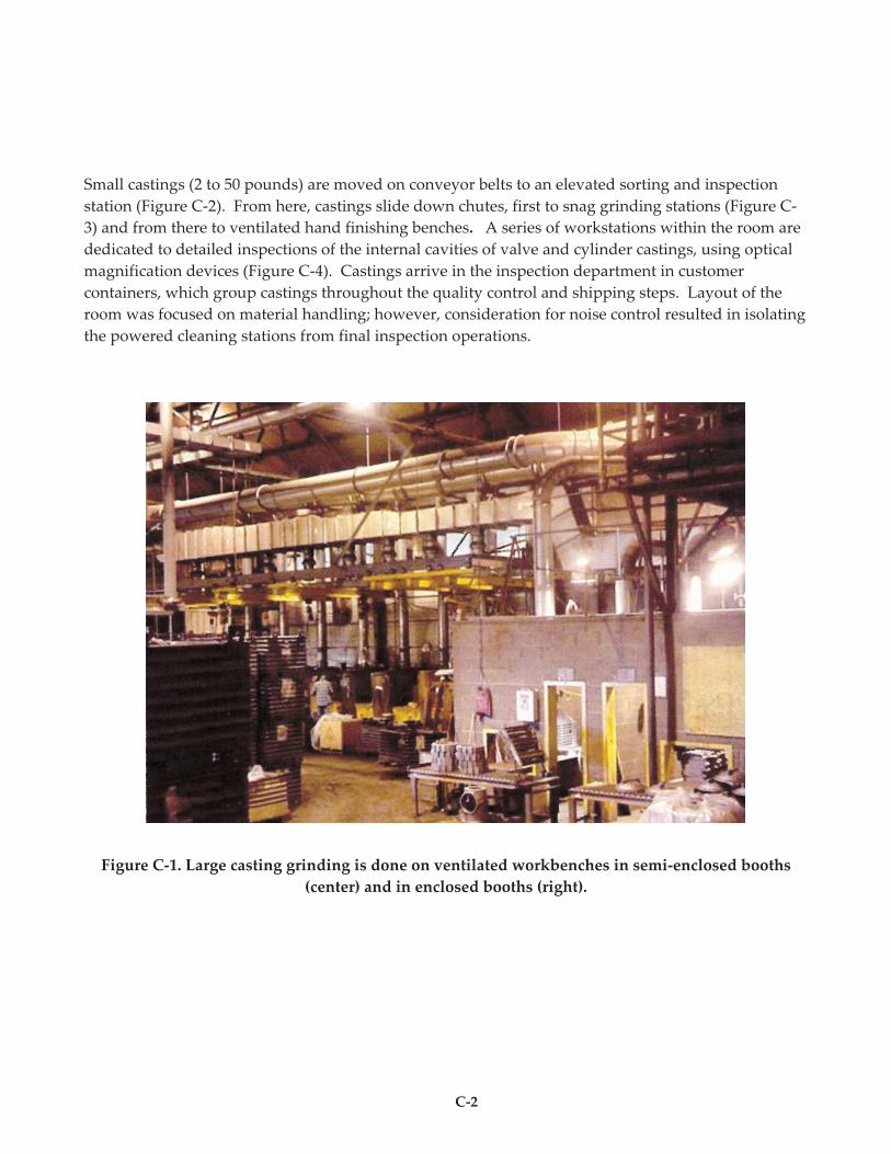
C-2
Small castings (2 to 50 pounds) are moved on conveyor belts to an elevated sorting and inspection
station (Figure C-2). From here, castings slide down chutes, first to snag grinding stations (Figure C-
3) and from there to ventilated hand finishing benches. A series of workstations within the room are
dedicated to detailed inspections of the internal cavities of valve and cylinder castings, using optical
magnification devices (Figure C-4). Castings arrive in the inspection department in customer
containers, which group castings throughout the quality control and shipping steps. Layout of the
room was focused on material handling; however, consideration for noise control resulted in isolating
the powered cleaning stations from final inspection operations.
Figure C-1. Large casting grinding is done on ventilated workbenches in semi-enclosed booths
(center) and in enclosed booths (right).
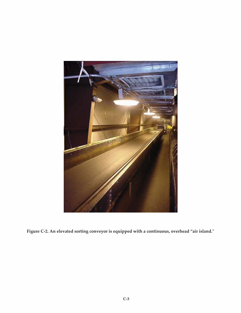
C-3
Figure C-2. An elevated sorting conveyor is equipped with a continuous, overhead “air island.”
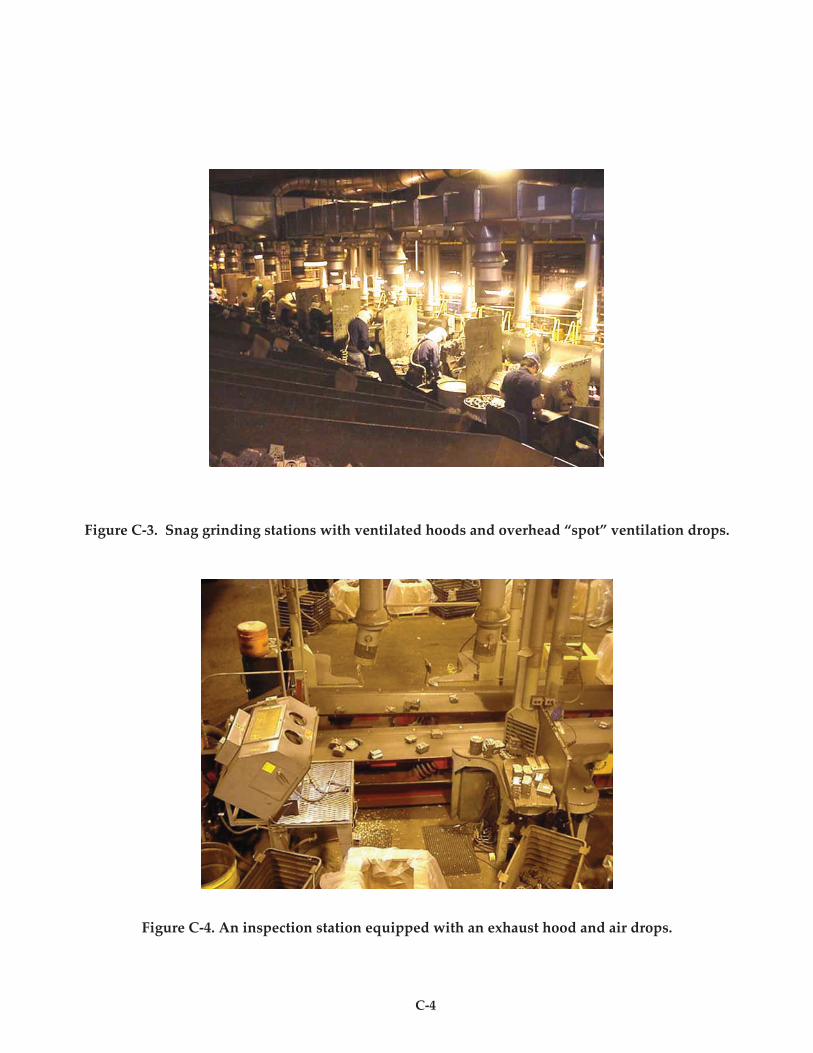
C-4
Figure C-3. Snag grinding stations with ventilated hoods and overhead “spot” ventilation drops.
Figure C-4. An inspection station equipped with an exhaust hood and air drops.
C-5
Dust Control and Climate Control
All dust-producing cleaning and finishing operations are locally exhausted (98 stations). The close
capture hoods employed were designed based on parameters recommended in the “Industrial
Ventilation Manual” of the American Conference of Governmental Industrial Hygienists (ACGIH).
The hoods are manifolded and ducted to a series of air cleaners, most of which are located on an
elevated mezzanine within the department. The indoor location was selected because it was desired
to recirculate the cleaned exhaust back into the foundry.
Cartridge-type collectors were employed to accommodate the available height of the mezzanine. One
air cleaner, a non-recirculating baghouse handling snag grinders, was located outdoors. A baghouse
was selected for snag grinding to guard against the bridging of cartridge pleats with fibers. Bridging
has been known to occur with the use of the high-speed, vitreous bonded wheels used on foundry
snag grinders. Precautions against blinding were taken in all cartridge filters by using open pleat
designs.
Dust consolidation and disposal was simplified through the use of a pneumatic transport system. It
transfers the collected dust from all of the air cleaners on the mezzanine to a single ground-level
filtered receiver where the dust is automatically loaded into large sacks.
Recirculation of cleaned exhaust air back into the cleaning and finishing area is very reliable because
of the use of a three-stage filter system. Air passing through the primary dust collectors is
automatically refiltered by secondary dust collectors, referred to as safety monitoring filters (SMF). If
a cartridge in a primary filter unit develops a leak, the SMF will filter out any dust leakage through its
automatically recleaned filters and signal that there is a leakage. High efficiency, particulate air
(HEPA) filters are employed as a final stage, to backup the recirculation system.
The air mass balance of the new casting cleaning facility is presented in Figure C-5. The facility has
positive pressure in those foundry areas that are attached to the system. This pressure is created by
tempered (i.e., heated or evaporatively cooled) makeup air units, which direct air to 98 individual
adjustable air drops at the workstations. These air drops are preferred by workers because they are
located close above their heads and are individually adjustable in terms of amount and direction of
the air. Their use completely eliminates the need for pedestal fans to cool workers. The roof fans and
sidewall supply fans provide summer heat relief only.
The entire ventilation system is continuously monitored by a programmable computer with a touch
screen. Airflow parameters are controlled within preset ranges, with alarms to indicate any
out-of-range parameter.
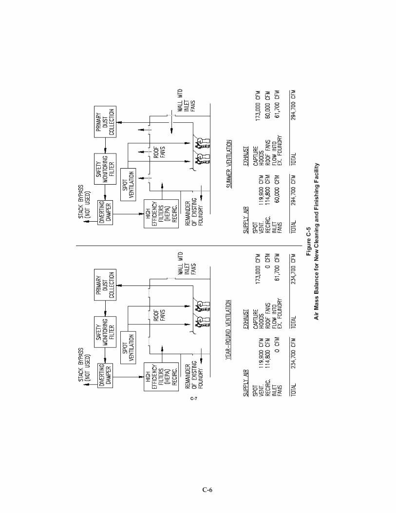
C-6
C-7
Ventilation System Performance
Following completion of construction and commencement of process operation, air sampling was
conducted to assure that stack emissions met the limits set by permit and that exposure of the
workers to respirable silica met the Occupational Safety and Health Administration’s (OSHA)
permissible exposure level (PEL). Worker training is ongoing in the new facility to educate workers
how to process a myriad of different size and shape castings while conducting the work in such a way
that the maximum effectiveness of exhaust capture hoods is realized.
Summary
Acme Foundry, its employees, customers, and neighbors are reaping the benefits of a well-engineered
foundry process addition. The same good results are anticipated for the ongoing program of
expanding and upgrading the foundry’s molding and casting department, which is being conducted
in the same integrated fashion.

C-8
D-1
Case History D
Ventilation Upgrade Reduces Silica Exposure
at
Grede Foundries, Inc. Reedsburg, Wisconsin
Peter Mark, Sr. Safety, Health, and Environmental Engineer
Grede Foundries, Inc. was established in 1920 and is an international leader in the foundry industry.
Grede has eight foundries in the United States and a joint venture in Mexico that produce gray iron,
ductile iron, steel, and aluminum castings. The Reedsburg, Wisconsin, plant was acquired by Grede
Foundries in 1951 and in 1954 was converted to produce ductile iron castings. The 300,000 square-foot
facility can generate up to 130,000 tons of ductile iron castings: calipers, crankshafts, flanges, yokes,
bearing caps, carriers, cases, knuckles, and exhaust manifold castings per year.
The safety and health culture established at Grede Foundries can be summed up with the following
statement: “No job is so important and no service so urgent that we cannot take time to perform our work in a
safe and healthful manner.”
Grede’s safety record has been continually improving for more than a decade. With the use of a
specially-designed safety manual, specific training, attitude seminars, safety audits, certifications,
hard work, and commitment, Grede has reduced the incidence of OSHA recordable cases to 1.9 cases
per 100 employees per year. The national average for iron and steel foundries is 14.8.
Although the company’s record exceeds the industry average, Grede believes safety and health is a
managed function and the goal is to manage accidents and job-related illness out of the workplace.
Part of this effort involves monitoring the air quality within the workplace. Grede Foundries has a
very aggressive industrial hygiene testing program and works diligently to minimize employee
exposures to hazardous chemicals using engineering controls, employee rotation and respiratory
protection devices.
Over the last several years, the Grede facility in Reedsburg has been working to improve employee
air quality (silica exposures) in the knockoff areas, concentrating on eliminating the source of the dust.
Exceptional silica exposure reductions were made in the cold knockoff area from a Disamatic mold
line. Process changes were made to achieve these exposure reductions and are detailed as follows.
Process Background
The knockoff process is conducted by one operator working within a booth. Much of the knockoff
operation is completed by manually striking the castings against the edge of the vibratory conveyor
or against the top of the metal sorting barrier. The trunk of the worker is bent slightly forward over
D-2
the conveyor during the course of the knockoff work. Dust is generated during the vibratory
conveying of the castings through the booth as well as by the knockoff process itself. As much of the
residual sand as possible is removed from the castings prior to entering the booth on a vibratory
conveyor. Minimizing adhered sand is essential to protecting workers from dust exposure whose
breathing zones are close to the dust source.
At the workstation, a local exhaust hood behind the conveyor was intended to pull dust back away
from the worker and evacuate the dust (Figure D-1). Supply air was located above and behind the
worker to support this airflow pattern and keep the air environment inside the enclosure well diluted.
The exhaust rate from the booth was around 8,000 cfm (ft3/min). In order to allow the operation of an
auto knockoff device on a monorail, the top of the side draft hood was angled back from the base
(normally the top of a side draft hood angles forward from the base). The “opposite” angle of the side
draft hood drew the emissions away from the point of dust generation (vibratory conveyor) in an
arced pattern which raised the airborne dust toward the breathing zone prior to drawing the air into
the capture hood.
The worker’s forward leaning of his upper body caused the air to “roll” in front of the operator and
confine some of the dust generated by the process into the vicinity of the breathing zone. Makeup air
was pushed unrestricted into the plenum over the workers head. Most of the makeup air exited the
front of the plenum and went directly to the collection exhaust hood, which was believed to multiply
the “rolling” action of the air in front of the worker. Much of the air behind the operator was stagnant
and became saturated with dust and silica. When the worker stood up straight during process breaks
his breathing zone was in the stagnant dust-saturated air.
Process Changes Made to Reduce Exposure
The makeup air was redistributed through the air supply plenum over the worker’s head by dividing
the plenum in two sections, front and back. The front section (closest to the worker) would have a
controlled airflow velocity of 125 to 175 ft/min using 25 percent perforations and the back section
would have a lower airflow velocity with 50 percent open perforations.
A baffle plate was added in front of the worker near the back side of the conveyor. The baffle plate
extended from the ceiling of the booth downward to the middle of the exhaust inlet opening. A
rubber material was used for the baffle plate to prevent injury if the worker accidentally struck the
plate while raising his hand/arm during the knockoff process.
The redistribution of the air in the plenum above the operator caused all the air in the booth to move
downward to about waist level and then over to the collection exhaust hood. The baffle caused the
dust emissions from the conveyor to cut under the baffle and “roll” behind the baffle away from the
worker’s breathing zone.
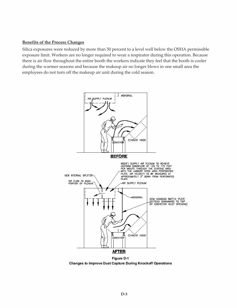
D-3
Benefits of the Process Changes
Silica exposures were reduced by more than 50 percent to a level well below the OSHA permissible
exposure limit. Workers are no longer required to wear a respirator during this operation. Because
there is air flow throughout the entire booth the workers indicate they feel that the booth is cooler
during the warmer seasons and because the makeup air no longer blows in one small area the
employees do not turn off the makeup air unit during the cold season.

American Foundry Society1695 N. Penny Lane
Schaumburg, IL 60173www.afsinc.org
ISBN: 978-0-87433-312-1
EC0702