OF COMPUTER AIDED DATABASE flflll flll I hEohhohEEmhhEI ...
148
RD-AtiM 782 DEVELOPMENT OF COMPUTER AIDED DATABASE DESIGN AND 1/2 MRINTENANCE TOOLS(U) AIR FORCE INST OF TECH WRIGHT-PATTERSON AFB OH SCHOOL OF ENGINEERING UNCLASSIFIED E R JRNKUS DEC 84 AFIT/GCS/EE/84D-iS F/G 9/2 NL I hEohhohEEmhhEI flflll flll EElllElllllEEE
Transcript of OF COMPUTER AIDED DATABASE flflll flll I hEohhohEEmhhEI ...

RD-AtiM 782 DEVELOPMENT OF COMPUTER AIDED DATABASE DESIGN AND 1/2MRINTENANCE TOOLS(U) AIR FORCE INST OF TECHWRIGHT-PATTERSON AFB OH SCHOOL OF ENGINEERING
UNCLASSIFIED E R JRNKUS DEC 84 AFIT/GCS/EE/84D-iS F/G 9/2 NL
I hEohhohEEmhhEIflflll flllEElllElllllEEE

Q.611111 .0 L611
I LL1-2.8
MICROCOPY RESOLUTION TEST CHARTNATIONAL BUREAU OF STANDARDS- 1963-A
.... . . . . . . . . . . .. . . . . . . . . . .. . .. . . . . . . . . .

REPR&IM)C*D AT'GOVERNMIT EXPENSE
0
DEVELOPMENT of COMPUTER AIDED DATABASE
DESIGN and MAINTENANCE TOOLS
THESIS
_'_ AFIT/GCS/EE/84D-/O Edward R. Jankus
+2Lt. USAF
4 UI
-_ " DTICLA" STATEMENTA_, IEL.CTE
Appowed I= public nleuq MR296vdutbmo ulimited____0
DEPARTMENT OF THE AIR FORCE BAIR UNIVERSITY
AIR FORCE INSTITUTE OF TECHNOLOGY
ILWright-Patterson Air Force Base, Ohio
85 03 13 104+. '.' .+- . , .., ,., -. .. . . .- . ' ,..+ ,..+, . , -- , . . .. - - , ,. . . .- , .- +8 5. , , . . .

AFIT/GCS/EE/84D-1O
DEVELOPMENT of COMPUTER AIDED DATABASE
PZSIGN and MAINTENANCE TOOLS
THESIS
AFIT/GCS/EE/84D-/# Edward R. Jankus
2Lt. USAF
Approved for public release; distribution unlimited
DTICSA 2~! 9

..4 AFIT/GCS/EE/84D-IO
DEVELOPMENT of COMPUTER AIDED DATABASE
DESIGN and MAINTENANCE TOOLS
THESIS
Presented to the Faculty of the School of Engineering
of the Air Force Institute of Technology
Air University (ATC)
In Partial Fulfillment of the
up Requirements for the Degree of
Master of Science
Edward R. Jankus, B.S.
Second Lieutenant, USAF
December 1984
Approved for public release; distribution unlimited
- .-.. - - .-- , . <. . o. . - • °o -° . , ° . t. K ,. •. .. . ° soe"" "'"

-J-
Preface
The purpose of this study was to perform a requirements
analysis of the database administrator's tasks and identify
those areas where CAD tools could be used to enhance the job.
To this extent, it was decided to develop several user
friendly systems for the DBA to define functional
dependencies of relations in a relational database, and
implement the code necessary to normalize unnormalized
relations into Third Normal Form.
With the work accomplished in this thesis as a basis,
other CAD database tools can be developed and the
normalization tool extended to include up to Fifth Normal
Form.
Throughout this thesis effort I have had a great deal of
help from others. I would like to express my deepest
appreciation and thanks to my thesis advisor Dr. Thomas C.
Hartrum, for his patience, understanding and assistance in
all of my times of need. I also wish to thank Dr. Henry
Potoczny, who as my thesis reader provided many constructive
insights. Not forgotten is Dan Zambon, LSI-11 lab engineer,
who provided assistance and encouragement thoughout the
implementation of this effort.
Finally, a special thanks to my wife Leilani for her
concern and never-ending belief in me, and to my parents
whom I can never thank enough.
Edward R. Jankus
ii
*. ' - . . .
--- ,* ...--
A . . . r .\.. Q.-

K- • - .. r"r V .
L
Table of Contents
Page.'-Preface .ii . . . . . . .
Peae..........** **o..........
List of Figures ..... ............ . . . . v
List of Tables ...... ................. vi
Abstract . . . . ................ vii
I. Introduction...... . . . . . .
Background ................. 1Problem.. ............ 3Scope . ............. . 3Approach ......... ............... 4Sequence of Presentation . . . . . . . 5
II. Requirements Definition .... ..........
Planning Phase . . . . . . . . . . . . 7Design Phase . .. .......... 7Operation and Control ........... 8Usage .................... 8Database Design ........... ... 8Computer Aided Design Tools 11Selection Criteria .......... 14The Selection ............. 18
III. Normalization Process Requirements Analysis
Introduction . . .......... 21Background . . ............... 21First Normal Form .......... 23Second Normal Form .......... .. .24
Third Normal Form 26Concept of Minimal over ....... 27Normalization Implementation . 34
Module BREAKOUT . . ....... 38Module REMOVE SUBS ....... 39Module TRANS DEPEND . . ..... 40Moul REGROUP .......... 42*. Module RGOP..................4
Module REMOVE DUPL . ....... 43Module NEWREL .. .......... 43
Test Criteria . . . . . . . . . . . . 44
iii
0° ' - " " " ° " " ° " " " " " " " " % " 2 ° ° " " °" " " " ' °"" ' " " " " " " °

Page
IV. Specifying Functional Dependencies ....
Introduction . ........... 46Methods for InputtingFunctional Dependencies ....... . 46
Voice Input. . .. ........ 48Touch Screen Input ......... 49Mouse Input .......... . 50Light Pen Input .. ......... 51Keyboard Input ... ......... 52Digitizer Pad Input ....... 52
Input and Output Enhancements . . .. 53Methods Selected ... ......... . . . 53
V. Normalization Tool ............
Overview .............. 55Defining Functional Dependencies:Screen Input Method . . . . . . . . . 58Defining Functional Dependencies:Mouse Input Method . ......... 63
VI. Testing, Suggestions andRecommendations .... .............. 69
Bibliography ...... .................. 73
Appendix A: User's Guide to AutomatedNormalization Tool . . . . . . . . . 74
Appendix B: Article Summary . . . . . . . . . . 88
Appendix C: Peripheral Devices . . . . . . . . . 110
Appendix D: Travis' NormalizationPsuedo Code ... ............ 124
Vita ......... ...................... 132
iv
... ... ... . ..- ............................................................. ]

List of Figures
Figure Page
1. Supplier Relation ...... ................ 22
2. Relation FIRST ......................... 24
3. Relations SECOND and SPQ ... ............ 25
4. Relations SC and CS ..... ............... .. 26
5. Structure Chart for module NORMALIZE ...... .. 36
6. Data Flow Diagram for module NORMALIZE ..... 37
7. Structure Chart for Normalization Tool ..... 56
8. Structure Chart for module FD .. .......... .. 59
9. Structure Chart for module MOUSEFD ........ .. 64
10. Structure Chart for Normalization Facility . . . 75
11. Cleveland Cadonics Card Modes of Operation . . . 119
12. Tektronics Operating Mode Changes .. ........ 122
INSPECTFD. [ 3
4AI
u°.S.p m. U
v
21I

List of Tables
Table Page
I. Database Design Tools Selection Matrix . . . . 16
Il. Summamouse Remote Settings ............. 112
III. Summamouse Status Data Format...........113
IV. Bit Pad One Data Format..............115
vi

AFIT/EE/GCS/84D-1O
Abstract
This thesis investigated what the tasks of the database
administrator are and detailed a list of computer aided
tools to assist the DBA in performing those tasks. A
selection criteria was established and two of the tools were
implemented.
The first tool implemented was an interactive user-
friendly Automated System for Normalizing Relations into
Third Normal Form. The basis for this tool is the concept of
a 'minimal cover' as presented by Jeffrey Ullman. If a
minimal cover is deduced from the set of functional
dependencies of an unnormalized relation, the resultant
relations are in Third Normal Form.
The second tool explores the user friendly graphics area.
It is a new front-end to the normalization tool that uses a
mouse to allow the DBA to specify the functional dependencies
that go into the normalization process. " Together, these
tools provide a very useful and complete system for the DBA
to normalize relations in a Relational Database.
[/'-'-1 -
v
vii
*4l ' - . , < " " " - -" " , '- -, " ''. "' -. " , - -" " .- . ., " -. . , :
.

Development of Computer Aided Database
Design and Maintenance Tools
I. Introduction
Background
The design, development and maintenance of a database can
be a very time consuming and complex task. One of the many
responsibilities of the database administrator (DBA) is to
make sure that the database performs efficiently and
consistently, with data integrity and limited data
redundancy. A key to this is to ensure that the database is
properly set up.
A relational database consists of tables (relations)
which themselves consist of unordered sets of entries. EachWof these entries is a meaningful collection of related
information about the objects around which the relation was
composed. Each table entry is called a tuple (row). Tuples
are themselves composed of fields called attributes
(columns).
In order for a database to perform with any merit,
certain design constraints must be built into the system.
Normalization theory, a useful aid in the database design
process, is based on the concept of normal forms. A relation
is said to be in a particular normal form if it satisfies a
certain specified set of constraints.
There are numerous normal forms and generally theiI iI.U
2' . .. . . ,. . . "

'higher' the normal form that the DBA can get a relation
into, the better. In other words, 3NF is more desirable than
2NF, which is more desirable than lNF. This is true because
the higher normal forms remove more of the undesirable
properties that lead to the insertion/deletion anomalies that
cause data inconsistency and loss of data integrity.
Normalization of relations is only one of the DBA's tasks
that can be enhanced through the use of computer aided design
(CAD) tools. CAD tools are user friendly interactive
programs that often simulate the behavior of some system or
task to the display console operator for further interactive
design and testing. For example, CAD programs have been used
extensively to design computer chips. Through interaction
with the program, the user designs the chip layout and
subsequently tests it on a simulator (another CAD tool) to
determine if it works. The user can then go back and make
any desired changes in the layout any number of times before
a prototype is ever built. Such a procedure saves time and
money and is used in many applications.
While a database is not a physical entity like a chip is,
it too requires design layout and testing. It would
therefore seem reasonable to try to create some CAD tools for
the DBA to use to handle his complex and time consuming tasks
faster, easier and more effectively.
2.,°-°

Problem
The purpose of this thesis is to solve two problems.
First, since the DBA has many tasks that he must perform, any
time saved on any of the tasks is beneficial. Normalization
is but one of the major tasks facing the DBA. The problem
with normalization is that getting relations into the desired
normal form is not always a trivial task. Like an art, it
often takes much time and does not present an obvious answer.
Obscure data dependencies may get past the DBA and foul the
system.
The second problem is to define the various tasks of the
DBA in the design, development and maintenance of a database,
and determine what other tasks can be improved through the
use of CAD tools. Hence, this study should have direct
application in the rapidly expanding database area.
Scope
The requirements analysis of the DBA's tasks was
performed to identify those areas where CAD tools could be
used. From the outcome of this search it was determined that
two tools would be implemented in this thesis.
The first tool is a tool to normalize unnormalized
relations into Third Normal Form. This entails completing
the work started by Travis [6] in this area, and carrying it
out to generate up to 3NF. In order to accomplish this, all
of the code that Travis wrote was translated to Whitesmith
'C'. There are several reasons for doing this. Whitesmith
3
4
-| - . . . o - - . -...--- ..-----. 2 - . fi

,-J . .' .- . n . - . - ° . - . - Q • . - o.-i--i . r . -. r - -. -.- - • . .
'C' is a more versatile language and has a better compiler
than the UCSD Pascal used by Travis, and the UCSD used by
Travis is no longer being run in the LSI-11 labs. In
addition, the interactive portion of Travis' system that
allows the DBA to determine functional dependencies was
redesigned to make use of the some of the capabilities of 'C'
and the H-29 terminals.
The second tool selected complements the normalization
tool. It is a completely redesigned user friendly front end
for the normalization tool that uses a mouse to make it
easier for the DBA to input functional dependencies.
Approach
In order to accomplish this study, first an in-depth
literature review was undertaken to explore other current
efforts in computer aided database design, and to find those
areas of the DBA's tasks that would benefit most from
computer aided tools. Very little work has been recorded in
these areas. With the literature review completed, the next
step was to detail the findings and select the tools to be
implemented.
The focus of the study then turned to implementing the
normalization tool. The first step was to examine the design
and code already written by Travis [6], to determine how it
works and to complete the design. Taking a top-down
structured approach, and using various graphics and user
interface concepts, the remaining modules were coded and
4

* U
tested until they worked for 3NF.
Once the normalization tool was completed, the attention
of the study was directed towards interfacing a Summagraphics
mouse to the LSI-11 system and designing the interface to use
the mouse to input the functional dependencies used in the
normalization process. This interface was designed in a top-
down structured fashion and implemented.
Finally, recommendations for future work on computer aided
database design were noted and detailed in the conclusion of
this thesis.
Sequence of Presentation
The remainder of this thesis is divided into five
chapters and four appendices. Chapter II is the requirements
definition chapter that describes the DBA's tasks and
outlines some of the possible tools that can be implemented
to assist the DBA. Chapter II also details the selection of
the tools implemented and explains why they were selected.
Chapter III details the normalization process and
presents an overview of normal forms. It details the
concepts of minimal cover that is used as a basis for the
normalization tool and presents the test case used to test
the software. Also included is a section on implementation
details of how the software is designed and how it works.
Chapter IV presents a discussion of various methods for
inputting functional dependencies and selects both of the
interfaces implemented to specify functional dependencies for
5
. - . -. - - .

the normalization tool. The methods selected are an improved
"version of Travis' keyboard entry system and a method which
uses a mouse to input the functional dependencies.
Chapter V details the Normalization tool driver and how
it works. The chapter also details the keyboard entry and
mouse method for inputting functional dependencies.
Chapter VI presents the conclusions obtained from
performing this thesis and recommendations for future
research and projects.
The four appendices at the end of this thesis contain the
User's Guide to the Normalization tool, an article summary of
this thesis, a detailed discussion of the peripheral devices
used, and the pseudo code developed by Travis.
6
"o "
-....................-......(s .'-..B.'

II. REQUIREMENTS DEFINITION
Before designing tools for the database administrator
to use, it is necessary to answer the somewhat nebulous
question, "what are the tasks of the database administrator?".
To answer this question several interviews and a literature
search were performed. A good overview of the DBA's duties
was found in the text by Weldon [12], and includes among
other things, the following suggestions:
Database Planning Phase:
1. Define database goals in support of organizationalgoals.
2. Develop and revise plans to achieve database goals,in particular, plan the transition to the databaseenvironment.
3. Assess the impact of changes in technology and* information requirements on the database.
4. Evaluate and select hardware and software to be used
to support database operations.
Database Design Phase:
5. Control the database design process through theintegration of data needs and the scheduling ofapplication development.
6. Provide expertise on methods for requirementsanalysis, database design and on the DBMS.
7. Make decisions concerning design trade-offs.
8. Guide and consolidate logical database design,and provide expertise in data modeling, definingdata, and integrating user's views.
9. Perform the physical design of the database, andselect storage and access methods.
10. Maintain a physical data description or datadictionary.
I-

Database Operation and Control:
11. Set and enforce data standards for data definition,
application coding, testing and system design.
12. Develop and install procedures for error detectionand resolution.
13. Set policies for database backup and recovery.
14. Establish and enforce a comprehensive databasesecurity policy that includes user authorization,internal controls, and controls on personnel.
15. Develop and monitor database performance indicators.
16. Resolve database operational problems through finetuning, reorganization, or redesign.
17. Maintain the DBMS and related software.
Database Usage:
18. Build, maintain, and distribute information about thedatabase to users, operators, and system developers.
119. Select the data dictionary package to be used.
20. Define and enforce standards for data naming, coding,documentation, and system development procedures[12:12-13].
Database Design
The design of a database remains somewhat an art, often
marked by the use of ad hoc methods of design. These ad hoc
methods often create a product that falls short of the
target. The reason is that there are many things to be con-
sidered when designing a database and ad hoc methods rarely
take all things into consideration. What is needed is a more
systematic and structured approach to database design, one
that lends itself to the use of computer aided design tools.
AU
r8

The DBA faces several major problems when designing a
database. First, he must determine the data requirements,
i.e., the portion of the 'world' to be represented. As with
any major software development project, finding out what the
users really need/want is one of the most difficult tasks,
for often the user himself is unsure of what he really wants.
Secondly, the DBA must consolidate the requirements of
several applications or departments into a unified set for
shared use. Third, the DBA must design for the future, that
is, anticipate changes in usage and design so that changes in
the system can be made without an entire redesign.
Once the data requirements are established, they must be
mapped into the logical data model and the physical storage
structures that are supported by the DBMS. Regardless of the
WDBMS used, the database design should follow the basic
standards of database design in order to minimize data
redundancy, avoid insertion and deletion anomalies, provide
adequate performance, and provide for ease in design changes
[13:283].
One structured iterative methodology for logical database
design suggested by Hubbard [5], and Vetter [10], goes as
follows:
1). Derive the local view (the representation of the dataelements and relationships that are required in thedatabase to support a given function), for one or two ofthe most important functions or applications to besupported by the database. This will form the frameworkof the design.
9

2). Invoke conceptual design procedures to gather, record and-. edit the data requirements of the organization.
* 3). Organize the data requirements into structures such assegments and hierarchies, for the given DBMS to be used.This logical design along with the conceptual design,forms the logical model of the database.
4). Select the next most important function or applicationand add its local view to the model and rederive thelogical model.
5). If any incompatibilities exist between the old andnew logical models, identify them and make corrections(trade offs).
6). Continue this process until all functions or applicationsare integrated and all inconsistencies, such as naminginconsistencies, are removed.
7). The edited composite model represents the unstructuredinternal view of the integrated database, but it is notyet complete. To complete the process, futurerequirements should be considered and processed in orderto help insure that the database structure developed isone that is flexible to change.
8). Finally, the result of this procedure yields the completemodel representing the unstructured internal view of theintegrated database. From this model the completelogical model and then a physical model can be derived.
As a practical consideration, this type of structured
iterative approach is usually not feasible by using purely
manual design techniques. Such a methodology is desirable
however, because it can provide a significant quality control
capability to the design process [5:23]. For these reasons,
all of the computer aided design tools discussed will be
useful in achieving such a structured iterative design.
I0I
10
.. -.- .°'-. -* . . . . . . -- ." "

Computer Aided Design Tools
Research and interviews into the idea of using computer
aided design tools to assist the DBA have met with mixed
results. First, since database design is still pretty much
an art, most people could not really come up with areas where
they felt computer aided design tools would be useful.
However, continued literature research revealed several good
design methodologies which in themselves provide opportunity
for computer aids. Many of the ideas found deal with
providing the DBA with some sort of report to assist him in
design trade-offs, finding errors in design, and increasing
design efficiency while at the same time reducing design time.
The following is a list of potential design tools discovered
through interviews and an extensive literature review:
For use in general database design:
1. One aid to database design would be a tool to help theDBA determine the functional specifications that the enduser desires. By producing exact formats of the desiredscreens and reports, computer aids can help end userssee how well the report will meet their needs.Experience also indicates that when this type of approachis used, the data requirements are less likely to changeduring the design process [5:24].
2. When integrating the various user's views, an alphabeticallist of names along with where they are used, and a listshowing the contexts in which all the qualifications ofthe data names are used, would be helpful in findingsynonyms, homonyms, and other naming inconsistencies.It could also be used to detect problems andinconsistencies in usage, format and meaning of the dataitem in the various local views [5:47].
3. An 'intersecting data elements report' containing a listof all data elements having more than one key. Such a
list could be used to help identify naming inconsistencies
II

and redundant data [5:96].
4. A data element usage matrix showing which data elementsare used by which functions [5:97]. This matrix is moreor less a condensed form of the list of #2, in a somewhatgraphical representation.
5. An interactive graphics display for the cononical designtechnique. It could draw the graphs and list theattributes and relations as the entities were added tothe graph. The graph defines the records with theirkeys and attributes and shows the associations betweenthe records [1:65].
6. Use of PSL/PSA to analyze requirements, design the globallogical database, define the database process, design thephysical database, and simulate database operation [2].
7. A tool to assist the DBA in conveniently meshingindividual subschemas or views together into the globallogical model. Naming and other inconsistencies wouldhave to be resolved by the DBA, perhaps interactivelywith the use of some of the forementioned design reports[10:73].
8. A local view report that gives the contributions of eachlocal view in the final logical view derived. Thisreport could be useful to a DBA who wants to evaluate theeffect of an application on the overall design [5:97].
9. Physical design tools. An on line system for thedesigner to make and specify physical design choices andoptions. A conversational terminal session can guidethe designer in selecting device type, access methods,block size, secondary data set groups, pointer options,and ordering choices [5:135-136].
Tools for relational database design:
10. A list of the transitive dependencies identified andremoved from the design. This could be useful to thedesigner who may want to reinsert some of thedependencies, at the expense of redundancy, in orderto gain performance and validity benefits [5:95].
11. A list of functional dependencies removed to obtainfunctional dependence. This could be used by the DBA toreinsert a dependency if it is important to the way theorganization functions. At a cost of increased dataredundancy, it may be better to have the dependency existfor performance reasons, or to more accurately or
12
4

conveniently represent the organization's requirements as" . they really are [5:128].
12. Identification of domains. A list of domains representedby the data elements, and of which elements (key orattribute) belong to which domain. The primary use ofthis would be for determining the potential for naturaljoins between derived relations [5:122].
13. Produce performance weights and relation sizes to assistthe designer with efficiency considerations such as:,
a) frequency of use of individual relations
b) frequency of use of the attributes within a relationc) frequency of need for joins [5:125-126].
14. A derived relations report showing the most frequentlyderived relations [5:127]. If the need for space-and-timecostly joins is too great, it may be desirable to createan extra view to contain that information that is derivedvia the join operation. This report and that of #15, gohand in hand with the frequency reports of #13.
15. A suggested joins report listing relations having commonelements. This could note which relations must be joinedto support the functional requirements of the database[5:127]. Also possible is a list of all the othernatural joins that are dynamically possible in thedatabase. This can be useful when new applications orfunctions are added to the database.
16. A redundant attributes report containing a list of dataelements appearing as attributes in more than onerelation [5:128].
17. A user friendly interactive tool to take a set offunctional dependencies, as specified by the DBA, andreduce the unnormalized relations to Third NormalForm [6]. Such a tool would help the DBA handle thiscomplex and time-consuming task faster, easier, and moreeffectively.
13. A user friendly (graphical or voice) interface to pointto attributes when defining functional dependencies.Such a tool could be especially useful as part of anormalization tool that requires the user to specify thefunctional dependencies for the normalization process. 2
19. A method for documenting the changes which relationsexperience during normalization. This could give theDBA and users access to what actually occurred throughthe execution of the normalization process [6:71].
13
:~~~~~~~~~~~~~~~~~~~.........-...:.: ...... ..........................? ::,- ... :: . . .. .. _- -; .-... - .' ....-. :.-.-' i., . .

20. A report stating which relations are affected by theaddition of new fields. Such a tool could be usefulto the DBA who may need to make trade-offs in designwhen a new function must be added to the database.It is also useful as an integrity constraint to insurethat no relations are inadvertently missed.
21. A tool to generate and help the designer evaluatealternative minimal covers to best suit theorganization's needs and/or requirements. This could bea tool to generate the 'best' set of functionaldependencies to meet the organization's needs, possiblyin terms of performance or convenience.
Selection Criteria
After defining the DBA's tasks and examining some
possible database design tools, it was necessary to choose
which tools would be implemented in this thesis. In order to
select the tools to be implemented, five selection criteria
were used. Each of the criteria was applied to each of the
database design tools, and the results are shown in matrix
form in Table 1.
The first set of criteria deals with the utility of a
given tool. Some tools may be useful in only one of the
three design phases (conceptual, logical, or physical), while
other tools may be useful in one or more of these phases. In
general, a tool that can be used throughout the database
development process is more valuable to the DBA than a tool
that has limited use. This statement requires some
qualification. In general, a tool that can be used in more
than one phase is more useful than one that is used in only
one phase, unless the latter is a tool that vastly reduces
14
4!
" " " ."".-"."° "",...................................................."....".......................... "," " "-"'."° "- " " " -

4l
the design efforts of a given phase. For example, a tool to
normalize relations in a relational database would take care
of the majority of work required in the logical design phase,
and as such, would be a very important tool even though its
use is limited to the logical design phase.
In the selection criteria matrix of Table 1, each tool
received an 'X' to represent its usefulness in one or more of
the design phases.
The second criteria is that of feasibility. Given the
current AFIT environment, time constraints and equipment,
does it seem feasible to implement a given tool in the short-
run, or even the long-run? Each tool has an 'S' under it if
it is achievable in the short-run (one thesis), an 'L' if it
is achievable in the long-run (several theses), or a '?' for
a tool that is not implementable given the current set of
constraints.
In selecting a tool for implementation as part of this
thesis, it was desirable to select from those that were
feasible in the short-run. The reasoning behind this
decision is two-fold. First, if the tool could be designed
and implemented in the short-run, it would be possible to get
useful feedback about the tool, by letting one of the
database classes here at AFIT work with it. Second, by
designing and actually implementing a tool, it would be
assured of development, and not fall by the wayside waiting
for somebody else to finish it. In other words, a usable
15I
, '

Table IDatabase Design Tools Selection Matrix
rier'%a u liv i in Dato , ,O I c a M o derI A p p e a
TOOL Des~qri Phse Psn sePhase
1 X L G Y 42 X X S G N 23 X X S G N 14 X X S _G N 15 X L G Y 46 X X X ? G Y I7 X L G Y 38 X S G N 29 X L D Y 1
10 X S D N 411 X S D N 312 X S D N 213 X L D N 114 X S D N 215 X S D N 216 X S D N 317 X S D Y 518 X S D Y 519 X S D N 320 X S D N 221 _ X L D Y 5
Key:L: Long-term G: General Y: Yes
S: Short-term D: Data N: NoModel
?: Unknown Dependent
16
.. - .. . . . .. . . . - . . ... .. --.....-..--.-. •.....-..... .. .-'- - . . . ..-;.. -

finished product would result.
The third set of selection criteria deals with whether or
not a tool is dependent on a particular data model
(relational, network or hierarchical). Tools that are data
model dependent are denoted with a 'D' in the selection
matrix, while the tools that are general in nature and
independent of the data model used, are denoted with a 'G'.
In selecting a tool for this thesis, it was desirable to
select one that was either general in nature or dependent on
the relational data model since those tools could be more
easily implemented given the current AFIT environment.
The fourth selection criteria concerns the interactive
design aspect. Interactive tools can aid the database
designer in making decisions and can reduce the time needed
for design by doing most of the work required. Interactive
tools can be very user-friendly and easier to use than report-
generating tools because they do not generate a paper mill
for the DBA to read and interpret. Each of the tools has a
'Y' under it if it is interactive, and a 'N' if it is not.
In selecting tools for implementation in this thesis,
emphasis was put on those tools which are interactive.
The last selection criteria is the all-encompassing,
"appeal to the author". I rated each of the tools on a scale
from 1-5 (low-high), for their personal appeal. From my
literature research and personal interests, I have come
across tools that are more interesting to me than others,
17
.. -. . .. . - . . .

- .. ..
namely, interactive tools and tools for relational or general
design. I believe this to be a valid selection criteria
since it certainly helps a project to have a particular
interest in the work one is doing.
The Selection
After considering the tools and selection criteria, the
decision was made to work on implementing two of the
forementioned tools. This section explains which of the
tools were selected and why.
The first tool to be implemented is the tool to take a
set of functional dependencies of relations for a relational
database and reduce these unnormalized relations to 3NF
(tool #17). The reasoning for picking this tool follows.
,. The normalization tool is a tool that is useful only i..
the logical design phase, but it is a tool that does most of
the work that has to be done in the logical design phase.
Once the functional dependencies are specified and the
relations normalized, the task is essentially complete. None
of the other tools has such a profound impact on a given
phase of the design process.
The normalization tool is definitely feasible within the
scope of this thesis. This tool would actually complete the
thesis by Travis [6], which set the framework for a system to
define the functional dependencies of relations for the
normalization tool to use. The work to be completed entails
the completion of the coding and implementation of the part
18

that does the actual normalization. When completed, this
tool will represent a usable finished product.
This tool is dependent on the relational data model but
that does not pose any problem since the groundwork for this
tool has already been laid by Travis. Also, relational
database systems are becoming very popular because of their
relative simplicity, so any useful tool that can help in this
growing area is beneficial.
The fact that this is an interactive tool makes it even
more attractive. As previously mentioned, interactive tools
can be very user-friendly and much easier to use than report-
generating tools. As such, this tool will be much easier to
use than trying to do the normalization process by hand.
Finally, the normalization tool has a lot of appeal. It
can save the DBA a vast amount of time and perform the
normalization process more effectively, freeing the DBA to
tend to his/her other duties.
The second tool to be worked on is the user friendly
(graphical or voice) interface to specify attributes when
defining functional dependencies (tool #18). This tool will
go along nicely with the normalization tool being developed.
It could be used to specify the functional dependencies
required as input to the normalization process.
This tool is of primary use in the logical design phase,
along with the normalization tool. The difference is that
this tool is an interface to the other. It is through this
19
t " 4

interface that the DBA must interact with the normalization
*tool. In order to make the normalization tool more user-
friendly and effective, a good interface is needed.
This tool is feasible under the time constraints of this
thesis, and equipment such as voice and various graphics
2.$ tools are available for use here at AFIT. The interface
would be the finishing touch for the normalization tool, so
the concern about data model dependence is not significant.
Furthermore, the use of various graphics devices in this
interface may be applicable for use in tools designed for
other data models.
The interface will obviously be interactive in order to
make the DBA's job easier. This will also help to promote
the use of the tool. The user-friendly interface also has a
great deal of designer appeal. It is part of a wide-open
area, where many new ideas can be conceived, developed and
evaluated for their potential. As new and better graphical
tools are developed, interest in the the man-machine
interface area is certain to grow.
In summary, the normalization and interface tools were
chosen for implementation because they go together well
to constitute a very useful and complete tool for the DBA in
the logical design phase of a relational database.
Furthermore, the design of the the user-friendly interface is
a very interesting and challenging area that holds much
promise in the design of future computer aided design tools.
2
- 20
20
.............................................
" " ° ~ * ". " * ° . . * ." . * " -. " "" " ° e*" ' ' "" ' *'" *° " " * . *" " " - * -" - **" ""°° • -" .-.. ". -" "•

III. NORMALIZATION PROCESS REQUIREMENTS ANALYSIS
Introduction
Before discussing the normalization process developed by
Travis and implemented in this thesis, a brief overview
of the concepts necessary to understand normalization in
general is given in this chapter. From there, the discussion
centers around the actual methodology used to normalize
relations in this thesis. Finally, implementation and
testing details are presented for the normalization tool.
Background
At this point, the term functional dependency (FD)I-
becomes significant. Functional dependency is defined as
follows:
Given a relation (table) R, attribute (column) Y of R isfunctionally dependent on attribute X of R, if each X valuein R has only one Y value in R associated with it [4:240].
In other words, each value of the attribute X will
functionally determine one and only one value for attribute Y
in relation R. Throughout this thesis, notation of the form
A -- > (B,C), denotes the functional dependency that
attribute 'A' functionally determines attributes 'B' and 'C'.
For example, in order to specify that a persons 'social
security number' (SSNO) determines his/her 'NAME' we would
write, SSNO -- > NAME, meaning that any given ssno will
determine one and only one name.
Another important concept is that of full functional
21
bI

dependence. According to Date [4:241],
"Attribute Y is fully functionally dependent on attribute Xif it is functionally dependent on X and not functionallydependent on any proper subset of X."
In other words, there can not exist a proper subset X' of the
attributes that make up X such that Y is functionally
dependent on X'. For example, in the SUPPLIER relation shown
in Figure 1 below, attribute CITY is functionally dependent
on the composite attribute (SUPPLIER,STATUS). CITY is not
fully functionally dependent on (SUPPLIER,STATUS), however,
because CITY is also functionally dependent on SUPPLIER
alone. Throughout this paper, the term functional dependenceI$
will be taken to mean full functional dependence unless
otherwise stated.
SUPPLIER SNAME STATUS CITY
S1 Smith 20 LondonS2 Jones 10 ParisS3 Blake 30 ParisS4 Clark 20 LondonS5 Adams 30 Athens
Figure 1. Supplier Relation [4:92]
The normalization process uses the predefined functional
dependencies to produce a collection of new relations,
equivalent to the original relation, but in a more desirable
form from the database point of view. Numerous normal forms
exist and generally the higher the normal form that the DBA
can get a relation into, the better (3NF > 2NF > 1NF). This
22
4 q*1

improvement results from the higher normal forms removing
more of the undesirable properties that lead to the insertion
and deletion anomalies that ultimately cause data
inconsistency and loss of data integrity.
Another important concept is that of keys. A key is a
collection of one or more attributes with values that can
uniquely identify each of the tuples (rows) of the relation.
Some relations contain more than one attribute combination
that uniquely identifies tuples in the relation. All of the
attribute combinations containing this property are called
candidate keys. The database administrator must decide which
candidate key to use, and this key then becomes the primary
key.
First Normal FormW
A database designer often starts with a raw relation or
data of the form:
SUPPLIER CITY STATUS PART# QUANTITY
S1 London 20 P1 20P2 10P3 1
S2 Paris 10 P1 12P4 18
The rules of normalization state that a relation in 1NF
contains attributes with atomic (single) values only. A
trivial process, placing a relation into 1NF requires that
the attribute(s) consisting of multiple values be broken up
into two or more single attributes as shown in relation FIRST
23
L%
.. . . . . . . . , . - .- • - - - . , . . . • , . - .' .' - " 2 "
" .

in Figure 2 [4:238].
SUPPLIER PART# QUANTITY CITY STATUS
Si P1 20 London 20Si P2 10 London 20$1 P3 1 London 20S2 Pi 12 Paris 10S2 P4 18 Paris 10
Figure 2. Relation FIRST.
Getting a relation into 1NF allows us to refer to each
attribute separately (needed for updates) and provides the
basis for further normalization.
Second Normal Form
Examining relation FIRST of Figure 2, it is easy to see
that some problems exist. First, the relation contains a lot
of data redundancy. The same CITY and STATUS values exist
for all like values of SUPPLIER. This redundancy of data
becomes very expensive in terms of the extra storage required
to hold the redundant data and in terms of the multiple
updates required, for example, if a SUPPLIER's status
changes. Every tuple in the relation would have to be
searched to find all of the tuples containing the given
supplier. This could take an unreasonable amount of time for
large relations. Also, if even a single tuple is missed in
the update, the data would become inconsistent [4:243].
The definition for 2NF states that a relation is in 2NF
24

~f. .~- 1).it is in LNF* 2). every attribute not a member of a candidate key is
functionally dependent on each candidate key of therelation [4:246].
Relation FIRST of Figure 2, while in INF, fails to satisfy
the requirements for 2NF. In order to get it into 2NF the
DBA must first determine the key for the relation. One
possible key could be (SUPPLIER,PART) -- >
(CITY,STATUS,QUANTITY), but it can also be seen that SUPPLIER
alone determines CITY & STATUS. When a subset of the key
determines some of the attributes, a partial dependency
exists, often causing data redundancy [4:244]. The DBA
removes these partial dependencies by splitting the table up
into two or more separate tables based on the functional
- dependencies of the relation (see Figure 3). For example,
since SUPPLIER -- > (STATUS, CITY), a new relation (table)
is constructed containing these attributes. Similarly,
since (SUPPLIER, PART#) -- > QUANTITY, a separate table is
constructed for those attributes.
SUPPLIER STATUS CITY SUPPLIER PART# QUANTITY
S1 20 London Sl PI 20S2 10 Paris S1 P2 10
S1 P3 IS2 PI 12S2 P4 18
Figure 3. Relations SECOND and SPQ.
25
.. ... . . .. . ,

Third Normal Form
The relations SPQ and SECOND have eliminated the data
redundancy problem but a problem still exists in the SECOND
table. SECOND has a non-key attribute (STATUS) dependent on
the key (SUPPLIER) thru another attribute (CITY). In other
words, SUPPLIER --> CITY; CITY --> STATUS; and
SUPPLIER --> STATUS thru CITY. The dependency of STATUS on
SUPPLIER, although it is functional, is also transitive via
CITY since each SUPPLIER value determines a CITY value and
this in turn determines the STATUS value. This implied
transitive dependency is not allowed in 3NF relations because
this transitivity leads to update problems [4:248]. For
example, it is not possible to state that a supplier in Rome
has a status of 50 until there is an actual supplier in Rome
because until such a supplier exists, there is no appropriate
primary key value. Likewise, deletion problems also exist.
Examining the functional dependencies of relation
SECOND reveals that it can be put into 3NF by breaking it up
into two new tables, SC and CS (see Figure 4), in order to
reflect the functional dependencies SUPPLIER --> CITY and
CITY --> STATUS.
SUPPLIER CITY CITY STATUS
Si London London 20S2 Paris Paris 10
Figure 4. Relations SC and CS.
26
. •• = ., +-+ == •,+++ + ' - .

Even with the data split up into several separate
relational structures, it is still possible to obtain the
original structure if so desired. Taking a join of the
relations created gives back the original relation, FIRST.
Called a lossless decomposition because no information is
lost, this desirable feature plays an important role in
database decomposition (4:247].
An aid to the database administrator, third normal form
(3NF) allows the database to grow and evolve naturally. With
relations in 3NF the database contains only limited data
redundancy, and updates are possible without the problems
encountered in the previous normal forms. For example, it
is now possible to have information on cities and their
status, where no supplier yet exists.
Concept of Minimal Cover
One way to normalize relations into 3NF, and in fact the
method used in this thesis, is based on the concept of a
minimal cover. By constructing a minimal set of functional
dependencies, the resultant family of dependencies is
automatically in 3NF [9:223-225]. We say that a set of
functional dependencies, F, is minimal if:
1). Every right hand side (RHS) of a functional dependency
in F has a single attribute, such as ABC --> D. This rule
guarantees that no attribute on the RHS is redundant
[9:224].
2). For all dependencies X -- > A in F, if the dependency
27
X -- > A is deleted, the resulting family is no longer
equivalent. This rule guarantees that no dependency in F is
redundant, since if a redundancy existed, the deletion of
X -- > A would leave an equivalent family of functional
dependencies.
3). For no functional dependencies X -- > A in F, and
proper subset Z of X, is F - [X -- > A] U [Z -- > A] equivalent
to F. This rule says that no attributes on the left hand
side (LHS) of the dependency are redundant [9:224].
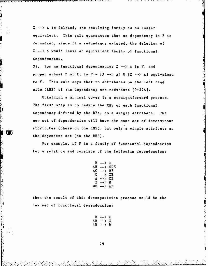
Obtaining a minimal cover is a straightforward process.
The first step is to reduce the RHS of each functional
dependency defined by the DBA, to a single attribute. The
new set of dependencies will have the same set of determinant
attributes (those on the LHS), but only a single attribute as
the dependent set (on the RHS).
For example, if F is a family of functional dependencies
for a relation and consists of the following dependencies:
AB -- > XDE
AC -- > BEC -- > XBA -- > CXX--B
DE -- > AB
then the result of this decomposition process would be the
new set of functional dependencies:
B--XAB -- > CAB -- > D
28

A
AC -- > BAC -- > EC -- >XC -- >BA-->CA -- >XX-->B
DE --> ADE -- > B
An important concept of the above decomposition is that
all previously defined dependencies can still be obtained
from the new set, so there is no loss of information
[9:225]. This is an example of a lossless decomposition.
The second step is to remove dependencies that contribute
redundant definitions. In other words, remove those
dependencies that have a subset of the original dependency
while determining the same single attribute. For example,
the dependencies broken out by step one can be reduced to the
set:
B -- > X
AB -- > D
AB -- > EAC --> E
* AC--> CA -- >XX -- >B
DE -- > ADE -- > B
The result was the elimination of the two dependencies
AB -- > C and AC -- > B. AB -- > C was eliminated because the
two dependencies AB -- > C and A--> C, achieve the same result
" D
t. 29
-.. : - . , .. ' . . . ... " " ". . o-

-. 7V
but A -- > C does it more efficiently. Since A -- > C has a
determinant set of attributes that is a subset of AB --> C,
the procedure says to eliminate the dependency with the
larger set of attributes and keep the dependency with smaller
set. In other words, since 'A' will get you 'C', there is
no need to carry along the extra attribute 'B'. The same
argument holds for AC --> B and C -- > B.
The third step in developing a minimal cover is to remove
any redundant explicit transitive dependencies that exist.
Any implicit transitive dependencies that exist are removed
in the final step of the process by separating them into
different relations. This is explained further in the last
step. With the remaining dependencies from step 2
AB -- > CAB -- > DAB -- > E
AC -- > BAC -- > EC -- >X
C -- >BA -- >CA -- >X
DE -- > ADE -- > B
we examine the RHS of each dependency and see if there are
any dependencies with a single attribute on the determinant
(LHS) that are the same as the attribute in question. The
first dependency, B --> X has the first attribute to satisfy 9the conditions searched for, since attribute X is also found
30

- - on the LHS of X -- > B. With this in mind, since B X-->
and X -- > B, it can be trivially deduced in this case that
B -- > B implicitly. The final check is to see if this
implied dependency exists explicitly. Since it does not exist
explicitly as well as implicitly in this example, nothing
can be removed in the first pass.
The fifth dependency, C -- > X, is the next dependency to
meet the criteria, since attribute X is also found on the LHS
of X -- > B. With this in mind, since C -- > X and X -- > B, it
can be deduced that C --> B implicitly. A search of the list
of dependencies reveals that C -- > B also exists explicitly
as well as implicitly, therefore the explicit dependency
should be removed to eliminate the transitive dependency.
Similarly, since A -- > C , C -- > X and A -- > X all exist in
the list of dependencies, A -- > X must be removed.
This process is repeated for the entire list of dependencies
until all redundant transitive dependencies have been removed
and the list of attributes on the RHS is exhausted.
The result of these three steps, shown below, is a
minimal cover (set) F for the given original unnormalized
relation. Each dependency, if treated as a separate
relation, would satisfy the definition of a 3NF relation
[9:242].
B- X
AB -- > DAB --> EAC -- > E MinimalC -- > X Cover
31*i- - - - - -- - - - - - - - - - - . ,. . .t{2

" A-->C
DE -- > ADE -- > B
This normalization process can be taken two steps further
to save space and reduce the amount of redundant data that is
stored in memory. First, rather than create a relation
(table) for each of the functional dependencies in the
minimal cover, it would be better to first collect those
functional dependencies with identical determinant attribute
sets (LHS) into groups. Doing this to the minimal set above
yields the new "minimal cover":
AB -- > DE
AC -- > E
A -- >C
DE -- > BA
Now instead of 9 relations and 24 attributes, it is possible
to build 7 relations with a total of only 19 attributes.
This step can result in substantial savings in space,
especially for large databases.
It is possible to further reduce the number of relations
created by realizing that several of the functional
dependencies contain the same attributes, although in a
different arrangement, but the same none the less. Since
they do contain the same attributes, there is no need to
create a separate relation for each since this would in
32
. . . .. .".

essence create a duplicate table. For example, in this case
X -- > B and B -- > X. A relation created containing B and X
embodies both dependencies so it is only necessary to carry
one of them along. This results in the elimination of
X -- > B. Similarly, since both AB -- > DE and DE -- > AB still
remain and contain the exact same attributes, DE -- > AB can
be eliminated. This step was not considered in Travis'
original design.
The final step is to actually create the new relations
from the remaining functional dependencies. Creating a new
relation for each of the remaining dependencies guarantees
that any implicit transitive dependencies will be removed
(remember all explicit transitive dependencies were removed
earlier in the third step of the process). The new relations
are composed of the attributes that were involved in the
functional dependency that the relation was constructed from.
Each of the attributes of the new relation will have the same
domain as was in the original relation. The results of the
normalization process for this case would look like the
following 5 relations:
Relation Name: NewRelationlAttributes: BX
Key: B
Relation Name: NewRelation2Attributes: ABDE
Key: AB
Relation Name: NewRelation3Attributes: ACE
Key: AC
33
• '. '° . . . . . / '° -' °. • , . " -".' . , " " '. ." " • , °,". , ,° "° °' °. ", , " " [ ' '1 - -• '- T [ ' °1 " ' ' °L ,' " " " • °- ." " ° - I

Relation Name: NewRelation4Attributes: CX
Key: C
Relation Name: NewRelation5Attributes: AC
Key: A
The new relation names would have to be supplied by the DBA
at the time of their creation.
.- The result of this procedure yields relations in 3NF. It
is coincidental that there were 7 functional dependencies
defined originally and 5 resulting relations. In general,
there is no way to predict the precise outcome of the
procedure because if the functional dependencies were
supplied in a different order, a different but equally valid
minimal cover would probably result. Regardless of the order
@ the functional dependencies are supplied, however, the
procedure is guaranteed to remove data redundancy and
transitive dependencies, resulting in 3NF relations [9:224].
Normalization Implementation
The normalization portion of the system consists of 7
major modules and is based somewhat on the pseudo-code
developed by Travis (Appendix D]. All code is written in
Whitesmith 'C' so as to be compatible with the LSI-11's in
the AFIT digital engineering lab. Module NORMALIZE is the
0 executive driver module that calls each of the 6 submodules
in turn in order to normalize relations in accordance with
Ullman's concept of a minimal cover. Each module is designed
34
• ~~~~.... ..-. ".. -. . .... .... ..... ....- .. . ..,. . .',...-'-. . ..,.. '. ; ' ... ,. ,' . "'.

to perform one specific function. The modules are sequential
in nature, in other words, one procedure follows the other
with the output of one procedure as the input to the next
procedure until the last procedure is executed. In addition,
normalize calls a print function, PRINTFDS, after each step
in the process in order to provide the DBA with a step by
step view of the functional dependencies as they go through
the normalization process. This information is stored in
an archive file along with the names of the new relations
created and the old relation definitions, to provide an
audit trail in case questions arise in the future about the
new relations, the old relation or the functional
dependencies that were defined. This information can be very
useful in performing joins on the database in order to get
back the original relation. It can also be used as a
learning tool to demonstrate the steps in the normalization
process. This is in effect an implementation of tool #19
(see Chapter 2).
The 6 modules that NORMALIZE calls to perform the actual
normalization are: BREAKOUT, REMOVESUBS, TRANSDEPEND,
REGROUP, REMVEDUPL and NEWREL. Each routine performs one of
the steps in the normalization process as just defined in the
previous section. A structure chart and data flow diagram for
the normalization process can be found in Figures 5 and 6,
respectively.
35
4.

-
4
-~
I
N
0za,
7-4
I
0
C.)
a)
0
4
:4
4-
36
q
--- ~ -- U., - *

100
4a -
)
r-44 4.4
P4~- E! 0
M) +1' 0)9
4-1 0
1+4
04-
.C,I 4 J )01
0 04
.4 +3 -
:3+0
or-4-4 0)
P44
37 -

-" This normalization process differs from that originally
devised by Travis. Travis started by sorting the functional
dependencies in descending order. This step was determined
to be not worth the effort because the only benefit was to
simplify the TRANSDEPEND module somewhat, but it did not
seem worth the extra time and effort spent in sorting.
Travis also does not have a module to eliminate
dependencies that would result in duplicate relations being
created. Numerous other variations have been made to improve
the design and will be elaborated upon as they become
relevant.
Module NORMALIZE references a global pointer to the
relation structure currently being normalized. This makes it
easier for each of the sequential modules to work on the
relation by avoiding the passing of pointers to pointers on
down the line as each module is called.
Module BREAKOUT
Module BREAKOUT performs the first step in the process by
traversing the linked list of functional dependencies and
separating those dependencies that have multiple dependent
attributes into as many new dependencies as there are
attributes in the dependent set.
BREAKOUT starts with the first dependency in the list and
creates a new functional dependency structure for it. The
determinant attribute set is simply linked to the old
determinant set rather than recreating those structures for
38
* " q . .". . ' -. i , ~ ,

each attribute in the dependent set. This is more efficient
and saves time and space by having only one copy of the
determinant set around. Travis' design calls for the
creation of a copy of the determinant set for each of the
attributes in the dependent set.
BREAKOUT then assigns one of the dependent attributes to
the new dependency and then frees that particular attribute
from the dependent list. This continues until all dependent
attributes have been assigned to a new dependency. BREAKOUT
continues down the linked list until all functional
dependencies have been broken down into dependencies with a
single attribute dependent set.
Module REMOVE SUBS
REMOVESUBS is the module that removes those functional
dependencies which have subsets of determinant attributes as
determinant attributes of other functional dependencies. A
key to finding those dependencies with subsets is realizing
that only those dependencies with equal dependent attributes
need be examined.
The module works by using several pointers to examine the
list of functional dependencies. Mainptr is set to the head
of the list and Auxptr is used to traverse the list to try to
find a dependency with a like dependent attribute. Another
pointer, Trailptr, is used to follow Auxptr down the list and
is used when it is determined that Auxptr's dependency must
be removed. If a dependency is found with a like dependent
39 i
I ______
• . .- .,-, - . . . . . . . . -. - -. , . - . . . . - - . .. . . . - . ,. . .. <

4attribute, then the check is made to determine if a
determinant subset is present, and if one is, which of the
dependencies must be removed.
The determination is done by counting the number of
attributes in Auxptr's and Mainptr's functional dependencies.
Then, the name of each of Mainptr's determinant attributes is
compared to every attribute in Auxptr's determinant list, and
a count of the number of matches is taken. If the number of
matches is equal to the number of attributes of Auxptr's
determinant set, then it is Mainptr that should be removed.
If the number of matches is equal to the number of attributes
in Mainptr's determinant set then Auxptr is removed. If the
number of matches does not equal either of those two, then
there is no subset present for the pair of dependencies under
scrutinization, and Auxptr and Trailptr are advanced down the
list to try again. When Auxptr reaches the end of the list,
Mainptr is advanced one and Auxptr is reset to point to the
dependency one ahead of Mainptr and the process starts again.
The procedure ends once Mainptr has traversed the entire list.
Module TRANS DEPEND
TRANSDEPEND is the module that searches the functional
dependency list for any explicit transitive dependencies that
may exist and removes them if present. This module uses four
pointers to traverse the list and one trailptr which is used
to delete a dependency from the linked list. The four
pointers are Mainptr, Single, Auxl, and Aux2. Mainptr is the
40
.° .

pointer that traverses the linked list of functional
dependencies searching for the first dependency of a
transitive dependency situation. Mainptr is advanced down
the list after no transitive dependencies are found or after
there are no more transitive dependencies to be removed.
Single is a stationary pointer that points to the first
dependency in the list that has a single attribute for it's
determinant attribute set. It is used to establish a
starting point for Auxl and Aux2 to start searching for
transitivity from. If no single is found, the module
returns. The reason for this will become obvious in the next
paragraph.
Auxl starts out pointing to Single and is advanced down
the list (stopping only on those functional dependencies that
have single attributes in their determinant sets), until the
first part of a transitive dependency is found. The reason
for considering only dependencies with single attributes in
their determinant sets, is that since each dependent
attribute set is a single attribute, all multiple determinant
attribute sets can be ignored. If Auxl can not find the
first part of a transitive dependency, Mainptr is advanced
and Auxl reset to try again with the new dependency pointed
at by Mainptr.
If the first part of a transitivity is found, then Aux2
comes into action. Aux2 like Auxl, starts at Single and
traverses the linked list stopping only on dependencies with
41
.4. . . . . . . . .. . . ... ..

single attribute determinant sets. Aux2 tries to find the
last part of the functional dependency. If it is found it is
deleted, otherwise the explicit transitive dependency does
not exist and Auxl is moved one down the list to try again.
Module REGROUP
Module REGROUP consolidates into a single functional
dependency all of those dependencies that have identical
determinant attribute sets. This consolidation helps to
promote one of the main ideas behind databases: eliminating
redundancy of data. By regrouping those functional
dependencies with identical determinant sets, fewer relations
are created in the final step of the process.
REGROUP uses three pointers: Mainptr, Auxptr, and
Headptr. Mainptr starts at the head of the list and is
advanced down the list when no more dependencies can be
regrouped with Mainptr's functional dependency. Auxptr goes
down the list one dependency at a time looking for equal
determinant sets. If one is found, Auxptr's dependent
attribute is added to Mainptr's determinant set. This is
done by pointer manipulation rather than creating a new
structure for the new dependent attribute. The old
dependency is then deleted from the list with the aid of
Headptr, which stays one dependency behind Auxptr. This
process continues until Mainptr reaches the end of the list.
42
.~~. . .. .

• . - - -*°;-.---.-.-•-. - - .
Module REMOVE DUPL
Module REMOVEDUPL was not part of Travis' design but was
added because like REGROUP, it results in eliminating some
data redundancy. Furthermore, it produces a more correct
result since it is unlikely that the DBA would want two
relations in the database with the exact same attributes in
each.
The module again uses three pointers to traverse the list
of functional dependencies. Mainptr points to the first
dependency and is advanced when all duplicates are removed or
none are found. Auxptr moves down the list one dependency at
a time, followed by Trailptr, looking for a dependency with
the same amount of attributes. If Auxptr finds a dependency
with the same number of attributes there is a chance of
having a duplicate dependency (as far as the dependency
having the same attributes, order is not significant).
Having found such a dependency, all of the attributes in
Mainptr's dependency are compared to all of the attributes of
Auxptr's dependency. If the number of matches is equal to
the number of attributes then a duplicate has been found and
Auxptr's functional dependency is removed from the list.
The procedure continues until Mainptr reaches the end of the
list.
Module NEWREL
The final step is to actually create the new relations
from the regrouped functional dependencies. It is NEWREL's
43
i ".7•• .U

job to create a record structure to hold the relation
definition and query the DBA to produce a unique name for
each new relation. To assist the DBA, a list of the current
relations is displayed along with the names of the attributes
that will be put into the new relation. The module checks to
make sure that the name supplied for the new relation is not
a duplicate and then it initializes all values in the
relation definition. The initialization will access
information that was in the original relation definition,
such as domains and security information, as well as setting
the NORMALIZE switch for the relation so that the system will
not attempt to normalize it again.
After NEWREL creates all of the new relations from the
normalization of the old relation, NEWREL prints a copy of
the relation to the archive file and then removes the old
relation from the linked list of relations. With the
completion of NEWREL, control is returned to the NORMALIZE
module which in turn returns control to MAIN.
Test Criteria
The family of functional dependencies F which was used to
explain the minimal cover technique, was also used to test
the normalization software. This test was limited to the
normalization software itself and assumes that the procedures
developed by Travis perform correctly. While this test case
is specific in nature, because it follows Ullman's proven
minimal cover technique [9:223], the only "proof" necessary
44
4

is to show that the software has been designed and coded
correctly, and performs according to Ullman's procedures.
Before testing the package as a whole, each module was tested
individually, with one module being added and tested at a
time. The results of the tests were easy to follow since the
software was designed to print the results of each step to
the archive file.
Since all cases can not be tested, a specific test was
run to ensure that the routines worked correctly for 1 to 3
iterations of the loops inside each module (i.e. multiple
transitive dependency elimination), since it seems to be that
the biggest problem with modules containing loops that do not
perform correctly is that they tend to work for 0, 1 or
infinite iterations. As far as loops are concerned, the test
designed checks to make sure that the software correctly
performs up to 3 iterations. As for the correctness of the
results produced, since the minimal cover technique used is
fairly simple to follow, it can be done on paper first for
any test case and order of functional dependencies, and then
run using the normalization system to check the results.
The results of the tests were exactly as expected and
paralleled the steps the DBA would perform on paper if he had
done the normalization work by hand (see the example in the
minimal cover section). Again, the trail left by the normal-
ization software in the archive file was extremely valuable
in debugging and checking the correctness of the results.
45
* . . ... . . i . f'. ' * . * -- =.< ,' ' i ., : - ~ -- ' ' '

IV. SPECIFYING FUNCTIONAL DEPENDENCIES
Introduction
A key to any normalization system is the ability for the
DBA to specify the functional dependencies that will be used
to normalize a relation. Various input methods can be
realized and it was decided to investigate the possibilities
for their user-friendliness and feasibility in this study.
The following sections describe the various methods
considered and point out their strengths and weaknesses.
After considering the possibilities, two methods were
o e-,e1. ind these methods are described in detail in the
,.t" n r which covers the normalization tool.
Metho'2ds f')r Inputting Functional Dependencies
Regirdless of the method used to input functional
dependencies, certain criteria must be met. First, and most
basically, any automated system to normalize relations is
still dependent on the user to supply it with the functional
dependencies needed to normalize relations. Since only the
user (through the DBA) knows how the data are dependent on
each other, there is no way a system can normalize a relation
if it is not given the set of functional dependencies that
exist because knowledge of the functional dependencies cannot
be deduced from the names of the attributes given.
Therefore, since the user must interact with the system, the
interaction should be made as convenient and simple to
4: 464
. . . . .. .

understand as possible.
Second, in order to aid in the interaction, the system
should provide the user with a continuous listing of the
attributes contained within the relation to be normalized.
By doing so, the system helps the user to 'select' the name
of an attribute displayed in front of him, rather then having
the DBA remember all of the attributes in the relation.
Third, the actual specification of functional
dependencies should be as simple and quick as possible. The
software should be designed to accommodate the DBA. For
example, rather than having the DBA type in an attribute's
complete name, let the DBA specify an attribute by typing in
a short key number that is displayed alongside each of the
attributes.
There are two main methods which can be used to define
functional dependencies: to use some device to 'pick' an
option, attribute, etc., or to use some device to input the
desired option. Traditionally the approach taken was that of
making the user input the option desired. This method is
simpler to implement but is usually not as user friendly.
Making the user type in all responses can be an error prone,
tedious process. With the advent of various graphics devices
there has been an awakening to the concept of user
friendliness. User friendliness means making the tool easy
for the user to work with so that the user can concentrate on
the work he is trying to accomplish, rather than making the
47

T 1. .W, -d - 7
user concentrate on the tool and the job at the same time.
By making the tool so that the user does not have to be a
typist to use it, it generally becomes easier to use. In
order to accomplish this, many user friendly tools have taken
the approach where the user need only select or 'pick' a
response or action. This category of tools makes use of
state-of-the-art graphics devices such as light pens, mice,
touch screens, voice input, digitizer pad input and
joysticks. Each of these can be used to develop a tool where
the user can select or 'pick' options off of the screen. It
should be noted that although keyboard entry was not included
in the above options, it too can be used to develop a user
friendly tool but it does not lend itself to a 'pick' tool
(although one could conceivably be developed using the arrow
keys on the keyboard to move around and the return key to
signal the selection).
Since the purpose of this study is to develop user
friendly tools for the DBA to use, it was decided to employ
the selection method over the user input method. The
following paragraphs describe some of the various user
friendly input methods.
Voice Input. One of the most convenient ways to specify
functional dependencies is probably voice input. This
essentially frees the DBA's hands for other things. Such a
system is certainly feasible and one of the problems with
voice input systems (keying on a specific word) would be made
48
4|

easier by the fact that the DBA could say phrases such as,
"Name determines Rank", and the key phrase in every
functional dependency would be 'DETERMINES'. The system
could display the attributes on the screen for the DBA who
could talk his way through the normalization process as if he
were thinking aloud. Voice feedback could be added to give
instructions as well as tell the DBA what functional
dependency he just specified.
Certain problems do remain that make voice input systems
expensive and not yet perfected. One big problem is that
current technology has not yet solved some of the pattern
recognition problems of voice systems. For example, some
people pronounce words slightly differently than others and
the systems often have to be tailored to one person's speech
1W patterns. Even then, problems exist when a person develops a
cold and does not talk as the system expects. As technology
improves, this method will certainly be most appealing.
Touch Screen Input. Another relatively new technology
that could be used effectively is the touch screen terminal.
The system could display the attributes on one screen and
instructions on the same screen or another screen, and have
the user touch the attributes that belong in a functional
dependency. The system would have to prompt the user by
asking him to select determinant attributes and after he
selected one, ask if there are any more determinant
attributes. The same would have to be done with dependent
49

attributes. To answer the system, the DBA could touch a
yes/no box on the screen.
Touch screens seem to be another good input device that
allows the user to concentrate solely on the screen. The
main drawbacks seem to be making the user press a location on
the screen for what he wants, the need to clean the screen
often to assure performance, and their relatively high cost.
Mouse Input. There are several ways to use a mouse to
input functional dependencies. One way would be to use the
mouse to draw a line from attribute to attribute to define
the determinant attributes, and then refresh the screen and
repeat the procedure for the dependent attributes. This
scheme has several inherent problems however. The first
problem is the difficulty in figuring out which attribute is
being drawn to. The second problem is that the screen can
quickly become a cluttered mess if there are many determinant
or dependent attributes to draw to.
A better approach would be to use the mouse as a cursor
mover for the user to pick out attributes in the determinant
and dependent sets. In other words, as the user moves the
mouse around its pad, the cursor would be moved correspond-
ingly around the screen. The user could press one of the
mouse's keys when he has the cursor positioned over the
desired attribute. That attribute would then be selected and
highlighted in reverse video. This method is less tricky
than drawing but still requires that the user place the
50

cursor within a relative tolerance distance to the attribute.
--" .In either scenario, the system would require two CRT's to
be effective. One screen would be used to prompt the DBA and
provide instructions. The other screen would be used to
display the attributes and work with the mouse.
The mouse has some benefits and disadvantages as far as
user friendliness is concerned. As stated above, the user
must get the mouse's position within a specified distance of
the target attribute in order to select it. This would seem
a drawback to the mouse. Requiring this of the user can make
the tool more tedious than it is worth. Unlike touch screen
where you concentrate on the screen and 'pick' with the touch
of a finger, using the mouse requires the user to concentrate
on the screen and the manipulation of the mouse at the same
time. The main advantages of the mouse seem to be that it is
a cheaper and more available technology.
Light Pen Input. The light pen is another of the 'pick'
devices that could be used to input functional dependencies.
The system would first prompt the DBA to select determinant
attributes. With the light pen, the DBA would pick an
attribute after which the system would have to ask the user
if there are any more determinant attributes. The DBA would
have to answer by either typing his response or possibly
using the light pen to pick a response off of the screen.
Dependent attributes would be selected in the way after all
determinant attributes have been selected.
51
..........................................................................

T. -'7 -6 .- . - - -
Keyboard Input. The keyboard entry system is the most
conventional method of entry and should not be ignored. It
is certainly the least expensive approach and is probably the
best understood. Keyboard entry was the approach taken by
Travis to input functional dependencies.
The system tells the user that the relation has been
selected to be normalized and then instructs him to select
determinant attributes first, by typing in their
corresponding key number. After each attribute, the system
asks the user whether or not there are any more determinant
attributes. After all of the determinant attributes have
been specified, the process is repeated for the dependent
attribute set.
There are a variety of variations in which the user
interface could be set up. Perhaps the best is with two
screens, one for displaying a full screen of attributes, and
the other for instructions and prompts.
Digitizer Pad Input. A digitizer pad could be used in
conjunction with a high resolution graphics display as a
drawing or sketch pad for the DBA to 'draw' functional
dependencies in the same way that the DBA might draw them
with paper and pencil when he tries to define the functional
dependencies of a relation. For example, the DBA could draw
a bubble around the determinant attributes and then draw a
line to the dependent attributes. This method is similar to
the mouse input method and basically has the same benefits
52
"bI

-. - - - - ;7 . -. -7 -'.7 .v
and weaknesses. While the digitizer pad is more suitable to
drawing, the drawing could get very messy quickly. Also, it
would be hard to detect which attributes are circled and
there is a problem of trying to selectively erase an
erroneous line without erasing the entire screen.
Input and Output Enhancements
Regardless of the method used to input functional
dependencies, there are several options that can be added for
enhancement: color, reverse video, blinking, reordering or
indenting attributes that have been selected, and voice
feedback. For example, color could be used to color key
attributes one color, determinant attributes in another
color, and dependent attributes in a third color. Color
seems to attract attention to itself and can be used to
highlight important objects or the object of current
interest. When color is not available, highlighting or
reverse video can be used to show the attribute(s) selected.
Indenting and/or reordering of attributes can be used in
conjunction with any of the other methods in order to offset
selected attributes from the rest of the pack. Voice
feedback can also be very useful to prompt the user or get
his attention, especially when using more than one screen.
4 Methods Selected
The selection of functional dependency input methods was
based on several criteria: availability of the input device,
53

time available, and usefulness of the device in defining
functional dependencies. Of the previously mentioned
devices, only the mouse, digitizer pad and keyboard entry are
currently available for use in the LSI-11 labs. This cut the
selection down to three possible devices. Of these three,
two devices, the mouse and digitizer pad, can perform the
same basic functions and since it was desired to select
'different' input methods for comparison, it was decided to
select only one of these devices. Finally, because of time
constraints, the decision was made to implement a functional
dependency input method using the mouse.
The second method selected, the keyboard entry system,
was selected because it was the method partially implemented
by Travis, and a simple method was needed to input functional
* dependencies in order to test the normalization software
developed in this thesis.
The detailed descriptions of these input tools can be
found in Chapter 5 which details the workings of the
normalization tool interfaces.
54
D o 3, . ,. -. . . . o , -. ., ,'. . ... . . .. . . . . . . . . , . . .,. .. .-. , . . .. ... . . , .. . . . . .- ..- ..- .- i

V. NORMALIZATION TOOL
Overview
The tool to normalize relations into 3NF consists of two
main parts. The first part, the interactive user segment
which queries the DBA for functional dependencies, was
designed by Travis and completed in this thesis effort.
Basically, the interactive user segment provides a method for
the DBA to specify functional dependencies of relations to be
normalized. The second part is the actual set of routines
to do the normalization (discussed in Chapter 3). This part
is hidden from the user until the normalization is completed
and the user is queried to supply names for the new relations
created.
IThe upper level structure of the normalization tool for
the keyboard entry system is shown in Figure 7. The MAIN
module calls FILEOPENER which reads the input file that has
been created by Roth's [7] DBMGR program. DBMGR is written
in PASCAL and is currently executable only on CPM systems so
the data file should be created using DBMGR on a CPM system
and then transferred to an RT-ll formatted disk. This file,
SETUP.DAT, is then read and searched for the CPM end of file
(Control Z) which is subsequently removed along with any
trailing garbage in the file. The SETUP.DAT file is not
actually modified, instead, the file is rewritten to a file
called SETUP2.DAT which is then used to build the linked list
structure that holds the relations of the database.
55
.-" " - - -" - . . . ."- - - . '- --. • " " -' ' ". . ' . " " " " -6 " -: ' " " - ." - " '

ZVI
rM 0H
560

Once the file has been cleaned up, MAIN then calls GETREL
which reads the domain definitions from the SETUP2.DAT file
and immediately writes them back out to the output file
(OUTPUT.DAT). GETREL then reads in the relation definitions
and sets up the linked list structure for the relations and
their attributes. MAIN then goes down the linked list and
finds those relations that are not normalized and that have a
zero tuple count (the system can not normalize a relation
with data in it). When one is found, FD is called to query
the DBA for the functional dependencies that will be used to
normalize the relation. FD also sets up the functional
dependency structure for the normalize routines to use. Once
all of the functional dependencies have been specified, MAIN
calls PRINTFD to print the list of functional dependencies
to the archive file for future reference.
The normalization driver routine, NORMALIZE, is then
called to perform the actual normalization of the relation in
accordance with the functional dependencies specified
(details of the normalization process can be found in Chapter
3). Once this has been completed, the old relation is output
to the archive file for future reference, and the new
relation(s) are inserted into the linked list structure.
MAIN continues this process until all relations have been
processed or the DBA exercises his option to quit, in which
case the work completed up to that point will be saved in the
appropriate files. The final results of the normalization
57

tool are stored in two files, OUTPUT.DAT and ARCHVE.DAT.
OUTPUT.DAT contains the relation definitions for normalized
relations. ARCHVE.DAT contains the old relation, the
functional dependencies used to normalize it, and the names
of the relations created from it.
Defining Functional Dependencies: Screen Input Method
When an unnormalized relation is found (that contains no
data, i.e. tuplecount equals zero), MAIN calls the FD module
to query the DBA for the functional dependencies that will be
needed for the normalization module. The upper level
structure chart of FD is shown in Figure 8. When FD is
called, the system displays the message to the DBA:
"Relation xxxx is selected to be normalized", where xxxx is
the name of the relation. This is used to inform the DBA of
exactly which relation is being manipulated.
Next, a message is displayed to inform the user that the
first step is to define the determinant attribute set (the
attributes of functional dependencies on the left hand side).
The system follows a sequence of steps that entails
listing all of the attributes of the relation, asking the
user to choose one as a determinant attribute, and then
asking if there are any more determinant attributes to be
selected.
To aid the DBA in knowing exactly which attributes are in
the relation being normalized, module SHOWATTRIBS displays
attributes on the screen, four attributes to a line, with 20
58
., . . .'. . . - - ". '- " " i i , '
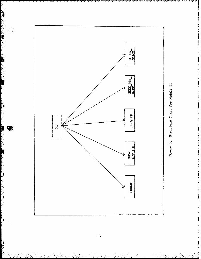
JlJ
.,I
m0
i"fb. I. ... ". . ..- _... .... . . _ ... .. . .. _-'. -'

*" . lines of display per screen. If more than 80 attributes
exist, module SCREEN is called. SCREEN pauses screen action
in order to give the user time to review his options. When
the DBA is ready, the DBA can hit any key for a continuation
of the listing. Each attribute is displayed with a unique
identifying number that allows the DBA to reference each
attribute without having to type in the name, by typing in
its number instead. By having the DBA type in only the key
number of the attribute, the process of specifying functional
dependencies is made faster, easier and less prone to typing
errors.
When the DBA enters the key number for the attribute
he/she wishes to select, the system checks to make sure that
it is a valid attribute number. If it is not a valid key
number, the system rejects the input and tells the user that
the input just made was out of range, try again. When the
user inputs a valid key number, FD calls the SEEKATRNAME
module to run down the list of the given relation's
attributes (find the key number element in the list) and
return the name of the attribute selected. The system then
displays the name selected to the user to show him the name
that was selected (user feedback). The name of the attribute
returned is also used to build the functional dependency.
After the DBA inputs a determinant attribute, the system
asks if there are any more to determinant attributes to be
named. If there are, the attributes are displayed again and
60
i "4.. ., . .. - " " - "- . "" '."""""""" ' '" . - ' -- '.•. " ' ' ' " " '- . . . . , """""'" - .; '''

the procedure is repeated. If not, 'he system proceeds to
the naming of the dependent attributes (those on the RHS).
As with the determinant attributes, the system sends the user
an introductory message, a listing of attributes, a query for
the naming of an attribute, and then the question asking the
DBA if there are any more dependent attributes to be named.
When the last dependent attribute of the functional
dependency is selected, FD calls SHOWFD to display the
functional dependency that was just defined. The DBA is then
given a chance to verify that the dependency shown is
correct. If the DBA decides that he/she no longer desires
the functional dependency or has made a mistake in defining
it, the dependency is destroyed. If the DBA verifies the
dependency, then module FD calls CHECKMATCH to make sure the
dependency just defined is not a trivial functional
dependency (one such as A -- > AB, where an attribute on the
determinant side also appears on the dependent side of the
functional dependency). If a trivial dependency is found,
FD writes a message to the user telling him the dependency
was trivial and then removes the functional dependency from
the linked list. Once it is determined that the functional
dependency specified is valid, the system asks the DBA
whether or not there are any more functional dependencies to
be defined for the current relation. If there are, the
process of defining determinant and dependent attribute sets
is repeated until all functional dependencies for the current
61
- ...-.,-. . . .,. . . . . .. ...... ........... :- . . .

relation have been defined. Once all the functional
dependencies have been defined, control is passed back to
MAIN which immediately calls the NORMALIZE module to
normalize the relation with respect to the functional
dependencies defined for the relation.
Module FD is a self-prompting interactive user-friendly
module that has been designed and implemented for
consistency. The querying for determinant and dependent
attributes are done in a consistent manner. Each section of
the module that requests the naming of attributes produces
its own queries, accepts the responses and displays error
notices in exactly the same manner. By providing similar
procedures, consistently, the system helps reduce processing
errors and increases speed and ease of use.
1W Also, after a relation has been normalized, MAIN asks the
DBA if he/she wants to continue normalizing relations or end
the current session. If the DBA curtails the current
session, all of the relations (normalized or not) are written
to the output file OUTPUT.DAT with their normalization flags.
At a later time, the DBA could rerun the normalization tool
using the last output file as the new input file. The DBA
could then continue to normalize as many unnormalized
relations as desired. This makes the tool more convenient
for the DBA to use.
62.iI
-'"*

- ~ ~ ~ ~ j -7 7 . ~ ' Lw s h- - -
. ....- Definlin Functional Dependencies: Mouse Input Method
Using the mouse to input functional dependencies differs
from the keyboard input method. The upper level structure
chart for the mouse input method is shown in Figure 9.
When the mouse input method is used, upon invoking the
normalization tool a complete set of instructions is given to
the DBA on the first screen and via the Votrax speech
synthesizer, informing him/her how to calibrate the mouse and
use it to define functional dependencies. Every time the
mouse is powered up it must be calibrated to orientate its
optics and circuitry to the mouse pad. This can be done
40easily by moving the mouse diagonally across the mouse pad
from the lower left hand corner to the upper right hand
corner to the upper right hand corner and then placing it
back in its starting corner (bottom left). The mouse
initialization routine will assure that the mouse has been
calibrated and informs the DBA if it has, or tell the DBA to
repeat the process.
When an unnormalized relation is found and the mouse
input method is being used, MAIN calls the MOUSEFD module to
query the DBA for the functional dependencies that will be
used to normalize the relation. The mouse method, like the
keyboard entry method, makes use of two CRTs. One CRT is
* used to display instructions and prompts to the DBA while the
* -: second CRT is used to display the attributes and specify the
functional dependencies.
63
..... ............................. -.... ... .......................-~~~~~~~~~~~~~~~~~~~~~...-.-.........-.............,. . . ............... ,..... ....-. -'.'' ,, .... ,-, .,,,.--.
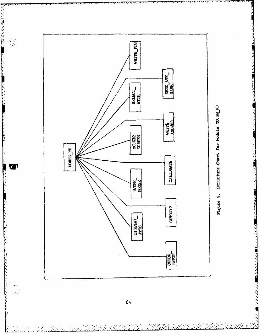
0244
r~l 0
'4
CM)
=12
64
* - r y 7 W S ,S - - - pi v r Lj -. . .- . - r - r r .. = - - . . -. e
When an unnormalized relation is found, the system
displays the message to the DBA: "Relation xxxx is selected
to be normalized", where xxxx is the name of the relation.
As with the keyboard entry system, this message is used to
inform the DBA of exactly which relation is being
manipulated.
Next, a message is displayed to inform the DBA that the
first step will be to define the determinant attribute set
for a functional dependency. The list of attributes are then
displayed on the second screen by module DISPLAYATTS, with
three attributes to a line and a new line every other line,
for a total of 24 attributes per screen display. If there
are more attributes the DBA can press the right and middle
keys of the mouse to get an additional listing. The reason
that only 24 attributes are listed per screen in the mouse
method (as opposed to 80 in the keyboard entry system), is to
make it easier for the DBA to select attributes by moving the
mouse. If too many attributes are displayed at once, the
screen will become too cluttered for the DBA to be able to
manipulate the cursor position via the mouse in order to
select an attribute. Also, since attributes would be so
close together on the screen, it would require the DBA to
move the cursor (via the mouse) within a very fine distance
of the desired attribute. In other words, the DBA would have
to have painstaking precision in selecting an attribute
because if he was off the target by a little bit he could
65
................ S. S.. .- -' ' -. lll*lll ililllll

mistakenly select the wrong attribute. Placing a fair amount
of space between attributes makes the selection process
easier since the screen is less cluttered (and therefore
easier to read) and DBA does not need 'deadly precision with
a mouse' in order to succeed.
With the attributes displayed on the second screen, the
DBA can now proceed by moving the mouse along the mouse pad
(which correspondingly moves the cursor) until he comes upon
the desired attribute. The cursor is moved by reading the
mouse's coordinates on the mouse pad with module TWEEKMOUSE.
The coordinates are then calibrated by module CALIBRATE and
then passed to module MOUSE2SCREEN in order to convert the
coordinates into row and column numbers (needed for direct
cursor addressing). Finally, module GOTOXY2 is passed the
row and column number and performs the direct cursor
addressing needed to move the cursor to the corresponding
location on the screen.
To select the desired attribute the DBA presses the
center key on the mouse which causes MOUSEFD to call the
SELECT ATTR module. SELECT ATTR then calculates the number
of the attribute selected by the location of the cursor. The
SEEKATRNAME module then runs down the list of the given
relation's attributes and returns the name of the attribute
4 selected. That attribute is then displayed in reverse video
to show the DBA which attribute he selected.
After a determinant attribute has been selected the
66

system asks the DBA if there are any more determinant
attributes to be named. This is done via the first screen and
the Votrax (in order to get the DBA's attention). The DBA
can answer the system's questions by pressing the left key
on the mouse for 'no' and the right key for a 'yes'. Module
WAIT4ANSWER waits until there is a change in the status of
either the left or right keys. If there are more determinant
attributes to be specified, the attributes are displayed
again and the process is repeated.
When all of the determinant attributes for a functional
dependency have been specified the system proceeds to the
naming of the dependent attributes. The procedure is exactly
the same as with the determinant set except for the system
message telling the DBA to select dependent attributes.
After the last dependent attribute of the functional
dependency has been specified, the system calls SHOWFD to
display the functional dependency that was just defined.
This gives the DBA an opportunity to verify that the
dependency shown is correct, by pressing the right key of the
mouse to answer yes or the left key to answer no. If the DBA
decides that he/she no longer desires the dependency or has
made a mistake in defining it, the dependency is destroyed.
If the DBA verifies the functional dependency, the system
then calls CHECK-MATCH to make sure the functional dependency
just specified was not trivial, and removes it if it was.
Then the system asks the DBA (via the first screen and the
q _
'e 67
i~i :; i :[ :• "'• -''''" " "' "" -"' " ' '" " '

.............
Votrax) if there are any more functional dependencies to be
defined for the current relation. If there are, the process
of defining determinant and dependent attributes is repeated
until all functional dependencies for the current relation
have been defined. Once all functional dependencies have
been defined, module WRITEFDS is called to write the
functional dependencies to a file (FDFILE.DAT). When all
functional dependencies have been defined for all of the
relations the DBA wishes to normalize, control is returned to
MAIN which then closes files and completes execution.
To normalize the relations when the mouse method is used,
it is necessary to run a second program (P2NORM) which reads
in the relations and their functional dependencies, recreates
their linked-list structures, and then calls the NORMALIZE
module to normalize the unnormalized relations with respect
to the functional dependencies that have been defined. As
with the keyboard entry method, the DBA is required to type
in the names for the newly created relations.
It was necessary to divide up the program to define
functional dependencies with the mouse and normalize the
relations into two parts because of the size of the code and
the memory limits of the LSI-11 systems. Program P2NORM
contains the modules to perform the normalization and
functions exactly like the normalization tool used with the
screen input method, creating the same results and files.
68
I

:%'
C VI. TESTING, CONCLUSIONS AND RECOMMENDATIONS
Testing
The Normalization system was tested using both the
keyboard entry method and the mouse method for defining
functional dependencies. Several students that had taken the
database courses here at AFIT volunteered to try both methods
and answer questions concerning user-friendliness, ease-of-
use, and preference of tool (mouse or keyboard). On a scale
of 1-5 (with one being excellent and five being unacceptable),
user-friendliness received an average score of 2.2 for the
keyboard method and 1.4 for the mouse method. Ease-of-use
received average scores of 2.0 and 1.8. There was no clear
preference of tool, about half of the people preferred the
mouse method, the other half the keyboard entry method.
In less than a half hour, the students were able to learn
how to use both of the input methods, successfully define
functional dependencies, and subsequently normalize relations
without much difficulty. Most of the criticism dealt with
the speech quality of the Votrax, the somewhat laborous mouse
calibration procedure, and a few minor details concerning the
screen displays.
Conclusions
The goals of this thesis effort were to investigate the
tasks of the DBA and outline those areas where computer aided
tools would be most useful. Once this was established,
69
I

twenty-one tools were described and a selection process was
devised to select those tools to be implemented in this
thesis. The normalization tool selected was a completion of
the work started by Travis [6] and is integrated with the
standards of the database created by Roth [7].
With the initial research completed and the tools for
implementation selected, the effort of this thesis was
divided into two main areas of design, implementation and
testing: the front ends to the normalization tool which
allow the DBA to specify functional dependencies, and the
part to do the actual normalization of relations to 3NF.
While still in the analysis stage of Travis' design it was
determined that the entire system should be moved from the
UCSD PASCAL used by Travis to Whitesmith 'C' in order to
*avoid the problems encountered by Travis [6:691. This
involved rewriting and redesigning Travis' code to run under
Whitesmith 'C'. During the process, several errors in the
original design were corrected and numerous improvements were
made to take advantage of the 'C' language and the H-29
terminal's capabilities. One design flaw corrected in the
early stages was the addition of a module to eliminate any
trivial functional dependencies specified (since they are not
used to normalize a relation and would not have been removed
by the other modules of the normalization system).
After Travis' work was recaptured, with the FD screen
method for entering functional dependencies working, the next
4 *7
7 0 . - + - - . - ,k . ' % .- . • - + + " .- " " , " . + " - + + + . . 5

7~ 7 1 -
* step was to implement the normalization process from Travis'
pseudo code. After careful analysis of Travis' design it was
determined that the design was incomplete. In order to
complete the design several changes were made. First, the
module to sort functional dependencies was deemed a waste of
time and effort since it only served to simplify the coding
of the module that searches for transitive dependencies.
Second, a module to remove dependencies that have exactly the
same attributes was added (after the 'normalization' process
but before the new relations were created) to prevent the
creation of more than one relation with exactly the same
attributes in each relation, since creation of duplicate
relations is likely to defeat the purpose of database
management. Also added were modules to write to a file the
original relation, the functional dependencies used to
normalize it, and the names of the new relations created.
These routines provide an excellent way of maintaining a
record of the manipulated relations.
After the normalization modules were implemented and
tested the focus of the study turned to designing a new
interface for the normalization tool that uses a mouse as the
input device. The design and implementation of the basic
modules to allow the user to select attributes from the
screen (as opposed to typing in their key numbers) was
designed and implemented to a working stage. Future effort
should be directed at putting the finishing touches on the
71
L A _.,_q

implementation to make the mouse input front-end a more
complete user friendly tool.
Recommendations
This thesis effort, by investigating the tasks of the
DBA, detailed areas where computer aided tools could be used
to assist the DBA. Future thesis efforts could certainly
design and implement some or all of the twenty-one tools that
were described in Chapter 2. Another area that deserves
attention is the investigation, design and implementation of
a system to carry the normalization process up to 5NF. This
would be a challenging thesis for someone interested in
databases because, at the time of this thesis, there were no
published algorithms to perform the normalization to 5NF.
Furthermore, normalizing relations past 3NF can produce
undesirable relations. The challenges would include coming
up with the algorithms and determining when a relation should
be carried out to 5NF. Also, a utility could be added to the
normalization routines to handle the case of disjoint
functional dependency sets (where all of a relation's
attributes are not used).
The design and implementation of other front-ends to the
normalization tool is another fruitful area in the user
friendly design area. The front-ends suggested in Chapter 4
or any variations of the existing front-ends could be
implemented and then comparison tested by having an AFIT
database class work with each of the front-ends.
72

BIBLIOGRAPHY
1. Allred, Dean, "Consolidated AFIT Database," (Thesis)School of Engineering, Air Force Institute ofTechnology, Wright-Patterson AFB, Ohio, 1980.
2. David W. Taylor Naval Ship research and DevelopmentCenter. Information Systems Design Methodology: GlobalLogical Data Base Design. Bethesda Md. Aug 1982.
3. Cleveland Cadonics User's Manual. Cleveland CadonicsInc., 1982.
4. Date, C. J., An Introduction to Database Systems. (ThirdEdition) Massachusetts: Addison-Wesley PublishingCompany, 1982.
5. Hubbard, George. Computer Assisted Database Design.New York: Van Nostrand Reihnhold Company, 1981.
6. Travis, Charles, "Interactive Automated System forNormalization of Relations," (Thesis) School ofEngineering, Air Force Institute of Technology, Wright-Patterson AFB, Ohio, 1983.
7. Roth, Mark A., "The Design and Implementation of aPedagogical Relational Database System," (Thesis)School of Engineering, Air Force Institute ofTechnology, Wright Patterson AFB, Ohio, 1979.
8. Summamouse Technical Reference. Summagraphics
Corporation Publlication 84-DSMI-830. Fairfield, Conn.August, 1983.
9. Ullman, jeffrey D., Principles of Database Systems.(Second Edition) Maryland: Computer Science Press,1982.
10. Vetter, M. and Maddison, R., Database DesignMethodology. New Jersey: Prentice Hall, 1981.
11. Votrax Type N Talk User's Manual. Votrax Division ofFederal Srew Works, Troy Michigan, 1981.
12. Weldon, Jay-Louise. Database Administration. New York:Plenum Press, 1981.
13. Wilson, Max. "A Requirements and Design Aid forRelational Databases," IEEE SOFTE. 1981: p. 2 8 3- 2 9 3 .
73
.. . . . . . " . ... . *.. . . . . . . . . ."

APPENDIX A
User's Guide To The AFIT Relational Database System
Relation Normalization Facility
Introduction and Overview
The Relation Normalization Facility described in this
document is a program to provide the Database Administrator
(DBA) with the ability to normalize relations to Third Normal
Form (3NF). This facility contains two different front ends
that the DBA can use to interact with the program. The first
method is designed to be used primarily with the use of two
CRT terminals and a keyboard, and is written in Whitesmith
'C'. The second method for inputting functional dependencies
is also designed to be used with two CRT terminals and is
e# written in Whitesmith 'C', but in uses a Summamouse to define
the functional dependencies. The Normalization facility is
intended to be run on the LSI-11 microcomputers of the AFIT
Digital Engineering Lab under control of the RT-11 operating
system, version 4.0
The tool to normalize relations into 3NF consists of two
main parts. The first part, the interactive user segment
which queries the DBA for functional dependencies, was
designed by Travis and completed in this thesis effort.
Basically, the interactive user segment provides a method for
the DBA to specify functional dependencies of relations to be
normalized. The second part is the actual set of routines to
do the normalization (discussed in Chapter 3). This part is
74
1i ... .. i/'JJ liillJ i

hidden from the user until the normalization is completed and
* -the user is queried to supply names for the new relations
created.
The upper level structure of the relation normalization
facility for the keyboard entry method is shown in Figure 10.
MAIN calls FILEOPENER to open the input and output files as
well as calling the GETREL, FD, PRINTFD, NORMALIZE and PUTREL
modules when appropriate to do so.
MAI
0FD PR32iTFD
GLE= NORMLUIZE FUTREL
Figure 10 Structure Chart For Normalization Facility
750, . .. .

K
How to Use the Relational Normalization Facility: Keyboard
Entry Method.
To start the system, execute the file NORM on the disk
marked 'Keyboard Fd Entry Method'. The system disk must be a
Whitesmith 'C' disk and the data disk must contain the data
file containing the relation definitions and the NORM
program. When the system is run, MAIN calls FILEOPENER
which reads the input file that has been created by Roth's
[7] DBMGR program. DBMGR is written in Pascal and is
currently executable only on CPM systems so the data file
should be created using DBMGR on a CPM based system and then
transferred to an RT-11 formatted disk. This file,
SETUP.DAT, is then read and searched for the CPM end of file
(Control Z) which is subsequently removed along with any
trailing garbage in the file. The SETUP.DAT file is not
actually modified, instead, the file is rewritten to a file
called SETUP2.DAT which is then used to build the linked list
structure that holds the relations of the database.
Once the file has been cleaned up, MAIN then calls GETREL
which reads the domain definitions from the SETUP2.DAT file
and immediately writes them back out to the output file
(OUTPUT.DAT). GETREL then reads in the relation definitions
and sets up the linked list structure for the relations and
their attributes. MAIN then goes down the linked list and
finds those relations that are not normalized and that have a
zero tuple count (the system can not normalize a relation
76
.1

L with data in it). When one is found, FD is called to query
the DBA for the functional dependencies that will be used to
normalize the relation. FD also sets up the functional
dependency structure for the normalize routines to use. Once
all of the functional dependencies have been specified, MAIN
calls PRINT FD to print the list of functional dependencies
to the archive file for future reference.
The normalization driver routine, NORMALIZE, is then
called to perform the actual normalization of the relation in
accordance with the functional dependencies specified
(details of the normalization process can be found in Chapter
3). Once this has been completed, the old relation is output
to the archive file for future reference, and the new
relation(s) are inserted into the linked list structure.
MAIN continues this process until all relations have been
processed or the DBA exercises his option to quit, in which
case the work completed up to that point will be saved in the
appropriate files. The final results of the normalization
tool are stored in two files, OUTPUT.DAT and ARCHVE.DAT.
OUTPUT.DAT contains the relation definitions for the
normalized relations. ARCHVE.DAT contains the old relation,
the functional dependencies used to normalize it, and the
names of the relations created from it.
Defining Functional Dependencies: Keyboard Input Method
When an unnormalized relation is found (that contains no
data, i.e. tuplecount equals zero and normalize flag set to
77

false), MAIN calls the FD module to query the DBA for the
functional dependencies that will be needed for the
normalization module. When FD is called, the system displays
the message to the DBA:
"Relation xxxx is selected to be normalized", where xxxx is
the name of the relation. This is used to inform the DBA of
exactly which relation is being manipulated.
Next, a message is displayed to inform the user that the
first step is to define the determinant attribute set (the
attributes of functional dependencies on the left hand side).
The system follows a sequence of steps that entails
listing all of the attributes of the relation, asking the
user to choose one as a determinant attribute, and then
asking if there are any more determinant attributes to be
selected.
To aid the DBA in knowing exactly which attributes are in
the relation being normalized, the attributes are displayed
on the screen foir attributes to a line, with 20 lines of
display per s-reen. If more than 80 attributes exist the
listing is stopped temporarily when the screen is full in
order to give the DBA a chance to review the attributes.
When the DBA is ready, the DBA can hit any key for a
continuation of the listing. Each attribute is displayed
with a unique identifying number that allows the DBA to
reference each attribute without having to type in the name,
by typing in it's number instead followed by a <CR>. By
78

having the DBA type in only the key number of the attribute,
the process of specifying functional dependencies is made
faster, easier and less prone to typing errors.
When the DBA enters the key number for the attribute he
wishes to select, the system checks to make sure that it is
a valid attribute number. If it is not a valid key number,
the system rejects the input and tells the user that the
input just made was out of range, try again. When the DBA
inputs a valid key number, the system will find that
attribute and then display the name selected to the user to
show her/him the name that was selected (user feedback). The
name of the attribute returned is also used to build the
functional dependency.
After the DBA inputs a determinant attribute, the system
asks if there are any more to determinant attributes to be
named. If there are, the DBA types in a 'Y' or 'y', causing
the attributes to be displayed again, and then the process of
specifying a determinant attribute is repeated. If not, the
DBA types any other character (unless otherwise stated, when
a yes/no answer is required, any key pressed other than a 'Y'
or 'y' is considered to be a no answer) and the system
proceeds on to the naming of the dependent attributes (those
on the RHS). As with the determinant attributes, the system
sends the user an introductory message, a listing of
attributes, a query for the naming of an attribute, and then
the question asking if there are any more dependent
79
j'

attributes to be named.
-.- When the last dependent attribute of the functional
dependency is selected, FD displays the functional dependency
that was just defined. The DBA is then given a chance a to
verify that the dependency shown is correct. If the DBA
decides that he/she no longer desires the functional
dependency or has made a mistake in defining it, the
dependency is destroyed. If the DBA verifies the dependency
be typing in a 'y' or 'Y', then FD makes sure the dependency
just defined is not a trivial functional dependency (one such
as A --> AB, where an attribute on the determinant side
also appears on the dependent side of the functional
dependency). If a trivial dependency is found, FD writes a
message to the user telling him the dependency was trivial
and then removes the functional dependency from the linked
list. Once it is determined that the functional dependency
specified is valid, the system asks the DBA whether or not
there are any more functional dependencies to be defined for
the current relation. If there are, the process of defining
determinant and dependent attribute sets is repeated until
all functional dependencies for the current relation have
been defined. Once all the functional dependencies have been
defined, control is passed back to MAIN which immediately
calls the NORMALIZE module to normalize the relation with
respect to the functional dependencies defined for the
relation.
80
''.' -..- - ' " : ' - -' " - ., " i , -':-, - . - -' ' -''".- ". """ "- .-"-' - "-'- -" " "- '

Also, after a relation has been normalized, the system
asks the DBA if he wants to continue normalizing relations or
end the current session. If the DBA curtails the current
session, all of the relations (normalized or not) are written
to the output file OUTPUT.DAT. At a later time, the DBA
could rerun the normalization tool using the last output file
as the new input file. The DBA could then continue to
normalize as many unnormalized relations as he wants or has
time for. This makes the tool more convenient for the DBA to
use.
How to Use the Relational Normalization Facility: Mouse Input
Method.
Because of the size of the code, the Mouse Input Method
is divided up into two separate programs, PINORM and P2NORM.
PINORM is the program in which the functional dependencies
are defined with the mouse and P2NORM reads the functional
dependencies and does the actual normalization of the
relations.
To start the system, execute the file PINORM on the disk
marked 'Mouse Fd Entry Method'. The system disk must be a
Whitesmith 'C' disk and the data disk must contain the data
file containing the relation definitions and the PINORM and
P2NORM programs. When the system is run, MAIN calls
FILEOPENER which reads the input file that has been created
by Roth's [7] DBMGR program. DBMGR is written in Pascal and
is currently executable only on CPM systems so the data file
81

should be created using DBMGR on a CPM based system and then
transferred to an RT-11 formatted disk. This file,
SETUP.DAT, is then read and searched for the CPM end of file
(Control Z) which is subsequently removed along with any
trailing garbage in the file. The SETUP.DAT file is not
actually modified, instead, the file is rewritten to a file
called SETUP2.DAT which is then used to build the linked list
structure that holds the relations of the database.
Once the file has been cleaned up, MAIN then calls GETREL
which reads the domain definitions from the SETUP2.DAT file
and immediately writes them back out to the output file
(OUTPUT.DAT). GETREL then reads in the relation definitions
and sets up the linked list structure for the relations and
their attributes. MAIN then calls MOWSE_UP to give the DBA
instructions on how to get the mouse ready for use and how to
use it to define functional dependencies.
When the DBA has calibrated the mouse, MAIN goes down
the linked list and finds those relations that are not
normalized and that have a zero tuple count (the system can
not normalize a relation with data in it). When one is
found, MOUSEFD is called to query the DBA for the functional
dependencies that will be used to normalize the relation.
Once all of the functional dependencies of a relation have
been specified, MAIN calls WRITEFD to write the list of
functional dependencies to the FDFILE.DAT file for use by
P2NORM.
82
."-:- ;. "; .'i' .i'i' .i.i ?' ' . " " . - ".- -". ".. " " ' ' . .-" " " " ' '"" " " - . _ _ '" " ''' - ' ;- ." i

-
DBA to repeat the process again if the mouse has not been
properly calibrated.
When an unnormalized relation is found and the mouse
input method is being used, MAIN calls the MOUSEFD module to
query the DBA for the functional dependencies that will be
used to normalize the relation. The mouse method, like the
keyboard entry method, makes use of two CRTs. One CRT is
used to display instructions and prompts to the DBA while the
second CRT is used to display the attributes and specify the
functional dependencies.
When an unnormalized relation is found, the system
displays the message to the DBA: "Relation xxxx is selected
to be normalized", where xxxx is the name of the relation.
As with the keyboard entry system, this message is used to
inform the DBA of exactly which relation is being
manipulated.
Next, a message is displayed to inform the DBA that the
first step will be to define the determinant attribute set
for a functional dependency. The list of attributes are then
displayed on the second screen, three attributes to a line
and a new line every other line, for a total of 24 attributes
per screen display. If there are more attributes the DBA can
press the middle key of the mouse to get an additional
listing. The reason that only 24 attributes are listed per
screen in the mouse method (as opposed to 80 in the keyboard
entry system), is to make it easier for the DBA to select
84
* U
__ . .. . - . . . . . . ... , -.-LA.

- -r1I w - 1 - - - --- 9V % - - -. . '. r -
MAIN continues this process until all relations have been
processed or the DBA exercises his option to quit, in which
case the work completed up to that point will be saved in the
appropriate files. The final results of the PINORM are
stored in FDFILE.DAT.
Defining Functional Dependencies: Mouse Input Method
Using the mouse to input functional dependencies differs
from the screen input method. When the mouse input method is
used, upon invoking the normalization tool a complete set of
instructions is given to the DBA on the first screen and via
the Votrax speech synthesizer, informing him how to calibrate
the mouse and use it to define functional dependencies.
Every time the mouse is powered up it must be calibrated to
orientate it's optics and circuitry to the mouse pad. This
can be done easily by moving the mouse diagonally across the
mouse pad from the lower left hand corner to the upper right
hand corner and then placing it back in it's starting corner
(bottom left).
The DBA is then required to 'zero out' the mouse's
coordinates (make sure the origin is set at 0,0) by picking
the mouse up and placing it in the upper right hand corner
and then sliding it down along the diagonal to the bottom
ieft hand corner. This must be done three times to insure
correct results.
The mouse initialization routine will assure that the mouse
has been calibrated and inform the DBA if it has, or tell the
83

attributes by moving the mouse. If too many attributes are
displayed at once, the screen will become too cluttered for
the DBA to be able to manipulate the cursor position via the
mouse in order to select an attribute.
With the attributes displayed on the second screen, the
DBA can now proceed by moving the mouse along the mouse pad
(which correspondingly moves the cursor) until he comes upon
the desired attribute. When moving the mouse it is important
to keep it on the pad at all times.
To select the desired attribute the DBA presses the
center key on the mouse which causes the selected attribute
to be displayed in reverse video in order to show the DBA
which attribute he/she selected.
After a determinant attribute has been selected the
system asks the DBA if there are any more determinant
attributes to be named. This is done via the first screen
and the Votrax (in order to get the DBA's attention). The
DBA can answer the system's questions by pressing the left
key on the mouse for 'no' and the right key for a 'yes'. The
system will wait until there is a change in the status of
either the left or right keys. If there are more determinant
attributes to be specified, the attributes are displayed
again and the process is repeated.
When all of the determinant attributes for a functional
dependency have been specified the system proceeds to the
naming of the dependent attributes. The procedure is exactly
850-

q
- ,.... -. the same as with the determinant set except for the system
message (via the first screen and Votrax) telling the DBA to
select dependent attributes.
After the last dependent attribute of the functional
dependency has been specified, the system displays the
functional dependency just defined on the first screen. The
DBA is then given a chance to verify that the dependency
shown is correct. If the DBA decides that he/she no longer
desires the functional dependency or has made a mistake in
defining it, he/she presses the left key on the mouse and the
dependency is destroyed. If the DBA verifies the dependency
by pressing the right key on the mouse, the system proceeds
to check that the functional dependency specified was not
trivial and removes it if it is. Then the system asks the
DBA (via the first screen and the Votrax) if there any more
functional dependencies to be defined for the current
relation. If there are, the DBA presses the right key on the
mouse and the process of defining determinant and dependent
attributes is repeated until all functional dependencies for
the current relation have been defined. Once all functional
dependencies have been defined, module WRITEFDS is called to
write the functional dependencies to a file (FDFILE.DAT).
When all functional dependencies have been defined for all of
the relations the DBA wishes to normalize, control is
returned to MAIN which then closes files and completes
execution. To normalize the relations when the mouse method
86
4 -

is used, it is necessary to run a second program (P2NORM)
which reads in the relations and their functional
dependencies, recreates their linked-list structures, and
then calls the NORMALIZE module to normalize the unnormalized
relations with respect to the functional dependencies that
have been defined.
It was necessary to divide up the program to define
functional dependencies with the mouse and normalize the
relations, into two parts because of the size of the code and
the memory limits of the LSI-l1 systems. Program P2NORM
contains the modules to perform the normalization and
functions exactly like the normalization tool used with the
screen input method, creating the same results and files.
Normalizing Relations
After the functional dependencies for an unnormalized
relation have been defined the normalization process is
automatically called when the keyboard input method is used
and must be run using P2NORM when the mouse input method is
used. The normalization process itself is transparent to the
DBA until the very end when the new relations are actually
created. At this point the system displays the list of
current relations names on the second screen along with the
attributes that make up each of the new relation(s) and asks
the DBA to input a name for each of the newly created
relation(s) (one relation at a time). The name must be 25
characters or less with no blank spaces in the name.
8
L 87
4
- . ..

AD-Ai5i 782 DEVELOPMENT OF COMPUTER AIDED DATABASE DESIGN RND 2/2MAINTENANCE TOOLS(U) AIR FORCE INST OF TECHWRIGHT-PATTERSON AFB ON SCHOOL OF ENGINEERING N
UNCLASSIFIED E R JRNKUS DEC 84 AFIT/GCS/EE/84D-iB F/G 9/2 N
,mIonsoonshh
I Lm~h~hh

77 T. c- -- - - - - -
L3.
1.2.8
MICROCOPY RESOLUTION TEST CHARTNATIONAL 13UREAU OF STANDARDS- 1963-A
z--- - - - - - - - - - - - -- - - -

APPENDIX B
Development of Computer Aided Database
Design and Maintenance Tools
Introduction
The design, development and maintenance of a database can
be a very time-consuming and complex task. One of the many
responsibilities of the database administrator (DBA) is to
make sure that the database performs efficiently and
consistently, with data integrity and limited data
redundancy. A key to this is to ensure that the database is
properly set up.
A relational database consists of tables(relations) which
themselves consist of unordered sets of entries. Each of
these entries is a meaningful collection of related
information about the objects around which the relation was
composed. Each table entry is called a tuple (row). Tuples
are themselves composed of fields called attributes
(columns).
In order for a database to perform with any merit,
certain design constraints must be built into the system.
Normalization theory, a useful aid in the database design
process, is based on the concept of normal forms. A relation
is said to be in a particular normal form if it satisfies a
certain specified set of constraints.
There are numerous normal forms and generally the
88

'higher' the normal form of a relation, the better. In other
words, 3NF is more desirable than 2NF, which is more
desirable than 1NF. This is so because the higher normal
forms remove more of the undesirable properties that lead to
the insertion/deletion anomalies that cause data
inconsistency and loss of data integrity.
Normalization of relations is only one of the DBA's tasks
that can be enhanced through the use of computer aided design
(CAD) tools. CAD tools are user-friendly interactive
programs that often simulate the behavior of some system or
task to the display console operator for further interactive
design and testing. For example, CAD programs have been used
extensively to design computer chips. Through interaction
with the program, the user designs the chip layout and
subsequently tests it on a simulator (another CAD tool) to
determine if it works. The user can then go back and make
any desired changes in the layout any number of times before
a prototype is ever b.;ilt. Such a procedure saves time and
money and is used in many applications.
While a database is not a physical entity like a chip, it
too requires design layout and testing. It would therefore
seem reasonable to try to create some CAD tools for the DBA
to use to handle his or her complex and time consuming tasks
faster, easier and more effectively.
89

Problem
The purpose of this effort was to solve two problems.
First, since the DBA has many tasks that must be performed,
any time saved on any of the tasks is beneficial.
Normalization is but one of the major tasks facing the DBA.
The problem with normalization is that getting relations into
the desired normal form is not always a trivial task. Like
an art, it often takes much time and does not present an
obvious answer. Obscure data dependencies may get past the
DBA and foul the system.
The second problem is to define the various tasks of the
DBA in the design, development and maintenance of a database,
and determine what other tasks can be improved through the
use of CAD tools. Hence, this study should have direct
application in the rapidly expanding database area.
Scope
The requirements analysis of the DBA's tasks was
performed to identify those areas where CAD tools could be
used. From the outcome of this search it was determined that
two tools would be implemented in this thesis.
The first tool is a tool to normalize unnormalized
relations into Third Normal Form. This entails completing
the work started by Travis in this area, and carrying it out
to generate up to 3NF.
The second tool selected compliments the normalization
tool. It is a completely redesigned user friendly front end
90

for the normalization tool that uses a mouse to make it
easier for the DBA to input functional dependencies.
Approach
In order to accomplish this study, first an in-depth
literature review was undertaken to explore other current
efforts in computer aided database design, and to find those
areas of the DBA's tasks that would benefit most from
computer aided tools. Very little work has been recorded in
these areas. With the literature review completed, the next
step was to detail the findings and select the tools to be
implemented.
The focus of the study then turned to implementing the
normalization tool. The first step was to examine the design
and code already written by Travis (6], to determine how it
works and to complete the design. Taking a top-down
structured approach, and using various graphics and user
interface concepts, the remaining modules were coded and
tested until they worked for 3NF.
Once the normalization tool was completed, the attention
of the study was directed towards interfacing the mouse to
the LSI-11 system and designing the interface to use the
mouse to input the functional dependencies used in the
normalization process. This interface was designed in a top-
down structured fashion and implemented.
91

Sequence of Presentation
The remainder of this paper will discuss some of the
various tasks of the DBA and present 21 computer aided tools
that can be used to assist the DBA in performing those tasks.
The normalization tool and the two interfaces that were
developed to allow the DBA to specify functional dependencies
for the normalization tool are also detailed. Finally,
recommendations for future work on computer aided database
design are presented at the end of this paper.
Designing Tools for the DBA
Before designing tools for the database administrator
to use, it is necessary to answer the somewhat nebulous
question, "what are the tasks of the database administrator?".
To answer this question several interviews and a literature
search were performed. A good overview of the DBA's duties
was found in the text by Weldon [12], and includes among
other things, the following suggestions:
Database Planning Phase:
1. Define database goals in support of organizationalgoals.
2. Develop and revise plans to achieve database goals,in particular, plan the transition to the databaseenvironment.
3. Assess the impact of changes in technology andinformation requirements on the database.
4. Evaluate and select hardware and software to be usedto support database operations.
92
,., .°° .. . : .° r.,•. .. '-* . .... ° . ... . °,...-' .°.-.- .. . . 0-. = . °~ •..-. °"-,- - . -°I 'o

Database Design Phase:% L'* .
5. Control the database design process through theintegration of data needs and the scheduling ofapplication development.
6. Provide expertise on methods for requirements
analysis, database design and on the DBMS.
7. Make decisions concerning design trade-offs.
8. Guide and consolidate logical database design,and provide expertise in data modeling, definingdata, and integrating user's views.
9. Perform the physical design of the database, andselect storage and access methods.
10. Maintain a physical data description or datadictionary.
Database Operation and Control:
11. Set and enforce data standards for data definition,application coding, testing and system design.
12. Develop and install procedures for error detection
and resolution.
13. Set policies for database backup and recovery.
14. Establish and enforce a comprehensive databasesecurity policy that includes user authorization,internal controls, and controls on personnel.
15. Develop and monitor database performance indicators.
16. Resolve database operational problems through finetuning, reorganization, or redesign.
17. Maintain the DBMS and related software.
Database Usage:
18. Build, maintain, and distribute information about thedatabase to users, operators, and system developers.
19. Select the data dictionary package to be used.
20. Define and enforce standards for data naming, coding,
934 q
.. :§~'.f

documentation, and system development procedures. . [12:12-13].
Database Design
The design of a database remains somewhat a black art,
often marked by the use of ad hoc methods of design. These
ad hoc methods often create a product that falls short of the
target. The reason is that there are many things to be con-
sidered when designing a database and ad hoc methods rarely
take all things into consideration. What is needed is a more
systematic and structured approach to database design, one
that lends itself to the use of computer aided design tools.
The DBA faces several major problems when designing a
database. First, he must determine the data requirements,
i.e., the portion of the 'world' to be represented. As with
any major software development project, finding out what the
users really need/want is one of the most difficult tasks,
for often the user himself is unsure of what he really wants.
Secondly, the DBA must consolidate the requirements of
several applications or departments into a unified set for
shared use. Third, the DBA must design for the future, that
is, anticipate changes in usage and design so that changes in
the system can be made without an entire redesign.
Once the data requirements are established, they must be
mapped into the logical data model and the physical storage
structures that are supported by the DBMS. Regardless of the
DBMS used, the database design should follow the basic
94
:. . ." .. .'. v .:, " . - '.- - " - ."- . "% .' " " • "". ' : '..-" ' , '':' -'..'''- -% --9-.'4

standards of database design in order to minimize data
redundancy, avoid insertion and deletion anomalies, provide
adequate performance, and provide for ease in design changes
[13:283].
As a practical consideration, the structured iterative
approach is usually not feasible by using purely manual
design techniques. Such a methodology is desireable
however, because it can provide a significant quality control
capability to the design process [5:23]. For these reasons,
all of the computer aided design tools discussed will be
useful in achieving such a structured iterative design.
Computer Aided Design Tools
Research and interviews into the idea of using computer
UJ * aided design tools to assist the DBA revealed several good
design methodologies which in themselves provide opportunity
for computer aids. Many of the ideas found deal with
providing the DBA with some sort of report to assist him in
design trade-offs, finding errors in design, and increasing
design efficiency while at the same time reducing design time.
The following is a list of potential design tools
discovered through interviews and an extensive liLtrature
review:
For use in general database design:
1. One aid to database design would be a tool to help theDBA determine the functional specifications that the enduser desires. By producing exact formats of the desiredscreens and reports, computer aids can help end users
95
S ." .- - -- - - - --. ". . . " . " . . . .' " " . , -. . - - , . .. ._','-. ." '. ' . .- ", - -

see how well the report will meet their needs.Experience also indicates that when this type of approachis used, the data requirements are less likely to changeduring the design process [5:24].
2. When integrating the various user's views, an alphabeticallist of names along with where they are used, and a listshowing the contexts in which all the qualifications ofthe data names are used, would be helpful in findingsynonyms, homonyms, and other naming inconsistencies.It could also be used to detect problems andinconsistencies in usage, format and meaning of the dataitem in the various local views [5:47].
3. An 'intersecting data elements report' containing a list
of all data elements having more than one key. Such alist could be used to help identify naming inconsistenciesand redundant data [5:96].
4. A data element usage matrix showing which data elementsare used by which functions [5:97]. This matrix is moreor less a condensed form of the list of #2, in a somewhatgraphical representation.
5. An interactive graphics display for the cononical designtechnique. It could draw the graphs and list theattributes and relations as the entities were added tothe graph. The graph defines the records with theirkeys and attributes and shows the associations betweenthe records [1:65].
6. Use of PSL/PSA to analyze requirements, design the globallogical database, define the database process, design thephysical database, and simulate database operation [2].
7. A tool to assist the DBA in conveniently meshingindividual subschemas or views together into the globallogical model. Naming and other inconsistencies wouldhave to be resolved by the DBA, perhaps interactivelywith the use of some of the forementioned design reports[10:73].
8. A local view report that gives the contributions of eachlocal view in the final logical view derived. Thisreport could be useful to a DBA who wants to evaluate theeffect of an application on the overall design [5:97].
9. Physical design tools. An on line system for the
designer to make and specify physical design choices andoptions. A conversational terminal session can guidethe designer in selecting device type, access methods,block size, secondary data set groups, pointer options,
96

and ordering choices (5:135-136].
Tools for relational database design:
10. A list of the transitive dependencies identified andremoved from the design. This could be useful to thedesigner who may want to reinsert some of thedependencies, at the expense of redundancy, in orderto gain performance and validity benefits [5:95].
11. A list of functional dependencies removed to obtainfunctional dependence. This could be used by the DBA toreinsert a dependency if it is important to the way theorganization functions. At a cost of increased dataredundancy, it may be better to have the dependency existfor performance reasons, or to more accurately or
conveniently represent the organization's requirements asthey really are [5:128].
12. Identification of domains. A list of domains representedby the data elements, and of which elements (key orattribute) belong to which domain. The primary use ofthis would be for determining the potential for naturaljoins between derived relations [5:122].
13. Produce performance weights and relation sizes to assistthe designer with efficiency considerations such as:
a) frequency of use of individual relationsb) frequency of use of the attributes within a relationc) frequency of need for joins (5:125-126].
14. A derived relations report showing the most frequentlyderived relations [5:127]. If the need for space-and-timecostly joins is too great, it may be desirable to createan extra view to contain that information that is derivedvia the join operation. This report and that of #15, gohand in hand with the frequency reports of #13.
15. A suggested joins report listing relations having commonelements. This could note which relations must be joinedto support the functional requirements of the database[5:127]. Also possible is a list of all the othernatural joins that are dynamically possible in thedatabase. This can be useful when new applications orfunctions are added to the database.
16. A redundant attributes report containing a list of dataelements appearing as attributes in more than onerelation [5:128].
17. A user friendly interactive tool to take a set of
97

functional dependencies, as specified by the DBA, and". .reduce the unnormalized relations to Third Normal
Form [6]. Such a tool would help the DBA handle thiscomplex and time-consuming task faster, easier, and moreeffectively.
18. A user friendly (graphical or voice) interface to pointto attributes when defining functional dependencies.Such a tool could be especially useful as part of anormalization tool that require the user to specify the
functional dependencies for the normalization process.
19. A method for documenting the changes which relationsexperience during normalization. This could give theDBA and users access to what actually occurred throughthe execution of the normalization process [6:71].
20. A report stating which relations are affected by theaddition of new fields.Such a tool could be usefulto the DBA who may need to make trade-offs in designwhen a new function must be added to the database.It is also useful as an integrity constraint to insurethat no relations are inadvertently missed.
21. A tool to generate and help the designer evaluatealternative minimal covers to best suit theorganization's needs and/or requirements. This could be
qa tool to generate the 'best' set of functionaldependencies to meet the organization's needs, possiblyin terms of performance or convenience.
After considering the utility, feasibility, and appeal
of the tools, it was decided to implement tools #17, #18 and
#19. Together they compose a complete and useful set of
tools for the DBA to use in the design and maintenance of a
relational database.
Normalization Tool
The tool to normalize relations is based on the concept
of a minimal cover as developed by Ullman. By constructing a
minimal set of functional dependencies, the resultant family
of functional dependencies is automatically in Third Normal
98
• .• . . . . . . * -.. , - , . - ." - . -•.......•.. " .... .... . . . . . . .

Form [9:223-225].
The normalization portion of the Normalization Tool
consists of 7 major modules and is based somewhat on the
pseudo-code developed by Travis [Appendix D]. Each of the
modules is sequential in nature and performs a single step in
the minimal cover process, with the output of one moduleIbbecoming the input to the next module.
Ullman states the three requirements necessary for a set
of functional dependencies (FDs) to be a minimal cover.
First, each FD in the set of FDs can have one and only one
dependent attribute (the attribute on the right hand side).
This step entails 'breaking out' any functional dependencies
that have multiple dependent attributes into as many new FDs
as there are dependent attributes in the original FD. The
newly created FDs are then substituted for the the original.
For example, given the FD ABC -- > DE, the result of the
first step would be the functional dependencies ABC -- > D and
ABC -- > E. The original relation with two dependent
attributes is replaced by two new FDs. The meaning of the
first relation has not been lost because later in the process
FDs with similar determinant attribute sets can be regrouped.
The second requirement for establishing a minimal cover
is to remove redundant functional dependencies. This means
removing those FDs that have a subset of determinant
attributes that determines the same set of dependent
attributes. For example, given the FDs AB -- > C and
99
.. 1

A -- > C, the FD AB --> C should be removed because the FD
A -- > C conveys the same information. If A --> C by itself
then there is no reason to retain AB --> C; it is redundant
information.
The third requirement is to remove all transitive
dependencies that exist in the set of FDs. A transitive
dependency exists if a dependency can be removed from the set
of FDs and the resultant set is an equivalent family. For
example, given the FDs: A --> B, A --> C, and B --> C, it
can be seen that A implies C directly in one FD, as well
through attribute B (since A --> B and B --> C). Since a
transitivity exists with B and C, the FD B --> C must be
removed.
Performing these three steps on a set of FDs guarantees
that each dependency, if treated as a relation itself, would
satisfy the definition of a relation in 3NF [9:242].
However, because databases strive to reduce data redundancy,
the process can be taken two steps further.
First, rather than creating a relation for each of the
functional dependencies in the minimal cover, it would be
better to first collect those FDs with identical determinant
attribute sets into groups. For example, given the set of
FDs: A --> B, A --> C, and D --> E, after the minimal cover
technique has been applied the first two FDs can be combined
to form a single FD (A --> BC). This can result in
significant savings in space, especially for large databases.
100
L. t

It is possible to further reduce the number of relations
created by realizing that FDs which contain the same
attributes (in any order) will result in equal relations.
For example, given the FDs A --> BC and C --> BA, the
resulting relation in both cases is one containing
attributes ABC. Therefore there is no need to create a
separate relation for each FD since this would in essence
create a duplicate table in the database (and defeat the
purpose of the database). This step was not considered in
the original design by Travis.
Once these steps have been accomplished, the final step
is to actually create separate relation out of each of the
remaining FDs. As each FD is created, the system displays
the attributes of the FD, along with a list of the current
relations in the database, to the DBA so that he/she can
input a unique name for the newly created relations.
As an added part of the Normalization Tool, after each
step of the process in order to provide the DBA with a step
by step view of the FDs as they go through the normalization
process. This information is stored in an archive file along
with the name of the newly created relations and the old
relation definitions, to provide an audit trail in case
questions arise in the future about the new relations, the
old relations or the functional dependencies that were
defined. This information can be very useful in performing
joins on the database in order to get back the original
101
4 .; . , .. .... .,.. ,. .. .. .., . . . ..., .. .. .. . - . . - - . .. , : ; .- , , . . . ., .. .

16.
relation. It can also be used as a learning tool to
demonstrate the steps in the normalization process.
Methods for Defining Functional Dependencies
There are two main methods which can be used to define
functional dependencies: to use some device to 'pick' an
option, attribute, etc., or to use some device to input the
desired option, attribute, etc. Traditionally the approach
taken was that of making the user input the option desired.
This method is simpler to implement but is usually not as
user friendly. Making the user type in all responses can be
an error prone, tedious process. With the advent of various
graphics devices there has been an awakening to the concept
of user friendliness.
I %, Various devices can be used to input functional
dependencies. Among them are a voice input system, touch
screen input system, mouse input system, light pen input,
keyboard input, and a digitizer pad input system. Regardless
of the method used to input FDs, there are several options
that can be added for enhancement: color, reverse video,
blinking, reordering or indenting attributes that have been
selected, and voice feedback.
The selection of functional dependency input methods was
based on several criteria: availability of the input device,
time available, and usefulness of the device in defining
functional dependencies. Of the previously mentioned
devices, only the mouse, digitizer pad and keyboard entry are
102
" a &a ~." a,~

currently available for use in the LSI-11 lab.
Defining Functional Dependencies: Keyboard Input Method
When an unnormalized relation is found (that contains no
data, i.e. tuplecount equals zero), MAIN calls the FD module
to query the DBA for the functional dependencies that will be
needed for the normalization module. When FD is called, the
system displays the message to the DBA:
"Relation xxxx is selected to be normalized", where xxxx is
the name of the relation. This is used to inform the DBA of
exactly which relation is being manipulated.
Next, a message is displayed to inform the user that the
first step is to define the determinant attribute set (the
attributes of functional dependencies on the left hand side).
The system follows a sequence of steps that entails
listing all of the attributes of the relation, asking the
user to choose one as a determinant attribute, and then
asking if there are any more determinant attributes to be
selected.
To aid the DBA in knowing exactly which attributes are in
the relation being normalized, the attributes are displayed
on the screen four attributes to a line, with 20 lines of
display per screen. If more than 80 attributes exist the
listing is stopped temporarily when the screen is full in
order to give the DBA a chance to review the attributes.
When the DBA is ready, the DBA can hit any key for a
continuation of the listing. Each attribute is displayed
103
---------------------------------------------------• " " " • " o" " " " "° - " • " ° " " " * .'" " ° " * "° " " " ' " ° "

WIW 1. 9 1 -- - - - -b - -1 S - -i & --
with a unique identifying number that allows the DBA to
reference each attribute without having to type in the name,
by typing in it's number instead. By having the DBA type in
only the key number of the attribute, the process of
specifying functional dependencies is made faster, easier and
less prone to typing errors.
When the DBA enters the key number for the attribute he
wishes to select, the system checks to make sure that it is
a valid attribute number. If it is not a valid key number,
the system rejects the input and tells the user that the
input just made was out of range, try again. When the DBA
inputs a valid key number, the system will find that
attribute and then display the name selected to the user to
show him the name that was selected (user feedback). The
name of the attribute returned is also used to build the
functional dependency.
After the DBA inputs a determinant attribute, the system
asks if there are any more to determinant attributes to be
named. If there are, the DBA types a 'Y', causing the
attributes to be displayed again, and then the process of
specifying a determinant attribute is repeated. If not, the
DBA can type any character other than a 'y' and the system
proceeds on to the naming of the dependent attributes (those
on the RHS). As with the determinant attributes, the system
sends the user an introductory message, a listing of
attributes, a query for the naming of an attribute, and then
104
r

the question for if there are any more dependent attributes
to be named.
When the last dependent attribute of the functional
dependency is selected, the system displays the functional
dependency just defined and gives the DBA a chance to verify
it. If the DBA decides he/she has made a mistake in
defining the dependency, the dependency is destroyed.
Otherwise, FD makes sure the dependency just defined is not a
trivial functional dependency (one such as A --> AB, where an
attribute on the determinant side also appears on the
dependent side of the functional dependency). If a trivial
dependency is found, FD writes a message to the user telling
him the dependency was trivial and then removes the
functional dependency from the linked list. Once it is
determined that the functional dependency specified is valid,
the system asks the DBA whether or not there are any more
functional dependencies to be defined for the current
relation. If there are, the process of defining determinant
* -and dependent attribute sets is repeated until all functional
dependencies for the current relation have been defined.
Once all the functional dependencies have been defined,
* . control is passed back to MAIN which immediately calls the
NORMALIZE module to normalize the relation with respect to
. the functional dependencies defined for the relation.
Also, after a relation has been normalized, the system
asks the DBA if he wants to continue normalizing relations or
105
[o-.............. .. - .
. . . . . . * .. 6~~

end the current session. If the DBA curtails the current* .
session, all of the relations (normalized or not) are written
to the output file OUTPUT.DAT. At a later time, the DBA
could rerun the normalization tool using the last output file
as the new input file. The DBA could then continue to
normalize as many unnormalized relations as he wants or has
time for. This makes the tool more convenient for the DBA to
use.
Defining Functional Dependencies: Mouse Input Method
Using the mouse to input functional dependencies differs
from the screen input methcd. When the mouse input method is
used, upon invoking the normalization tool a complete set of
instructions is given to the DBA on the first screen and via
the Votrax speech synthesizer, informing him how to calibrate
the mouse and use it to define functional dependencies.
Every time the mouse is powered up it must be calibrated to
orientate it's optics and circuitry to the mouse pad. This
can be done easily by moving the mouse diagonally across the
mouse pad from the lower left hand corner to the upper right
hand corner and then placing it back in it's starting corner
(bottom left).
The mouse initialization routine will assure that the mouse
has been calibrated and inform the DBA if it has, or tell the
DBA to repeat the process again if the mouse has not been
properly calibrated.
When an unnormalized relation is found and the mouse
106

input method is being used, MAIN calls the MOUSEFD module to
query the DBA for the functional dependencies that will be
used to normalize the relation. The mouse method, like the
keyboard entry method, makes use of two CRTs. One CRT is
used to display instructions and prompts to the DBA while the
second CRT is used to display the attributes and specify the
functional dependencies.
When an unnormalized relation is found, the system
displays the message to the DBA: "Relation xxxx is selected
to be normalized", where xxxx is the name of the relation.
As with the keyboard entry system, this message is used to
inform the DBA of exactly which relation is being
manipulated.
Next, a message is displayed to inform the DBA that the
qV first step will be to define the determinant attribute set
for a functional dependency. The list of attributes are then
displayed on the second screen, three attributes to a line
and a new line every other line, for a total of 24 attributes
per screen display. If there are more attributes the DBA can
press the middle key of the mouse to get an additional
listing. The reason that only 24 attributes are listed per
screen in the mouse method (as opposed to 80 in the keyboard
entry system), is to make it easier for the DBA to select
attributes by moving the mouse. If too many attributes are
displayed at once, the screen will become too cluttered for
the DBA to be able to manipulate the cursor position via the
107

mouse in order to select an attribute.With the attributes displayed on the second screen, the
DBA can now proceed by moving the mouse along the mouse pad
(which correspondingly moves the cursor) until he comes upon
the desired attribute. When moving the mouse it is important
to keep it on the pad at all times.
.- To select the desired attribute the DBA presses the
center key on the mouse which causes the selected attribute
to be displayed in reverse video in order to show the DBA
which attribute she/he selected.
After a determinant attribute has been selected the0
system asks the DBA if there are any more determinant
attributes to be named. This is done via the first screen and
the Votrax (in order to get the DBA's attention). The DBA
can answer the system's questions by pressing the left key
on the mouse for 'no' and the right key for a 'yes'. The
system will wait until there is a change in the status of
*either the left or right keys. If there are more determinant
attributes to be specified, the attributes are displayed
again and the process is repeated.
When all of the determinant attributes for a functional
dependency have been specified the system proceeds to the
naming of the dependent attributes. The procedure is exactly
the same as with the determinant set except for the system
message (via the first screen and Votrax) telling the DBA to
select dependent attributes.
108
0 ' . . - - , . " • , , " , - ." ° . • , ". " , . ' .

F ,After the last dependent attribute of the functional
dependency has been specified, the system gives the DBA the
chance to verify the functional dependency and then checks to
make sure the functional dependency specified was not trivial
and removes it if it is. Then the system asks the DBA (via
the first screen and the Votrax) if there any more functional
dependencies to be defined for the current relation. If
there are, the DBA presses the right key on the mouse and the
process of defining determinant and dependent attributes is
repeated until all functional dependencies for the current
relation have been defined. Once all functional dependencies
have been defined, the functional dependencies are written to
a file. Control is then returned to MAIN who then closes
files and completes execution. The actual normalization is
done by executing another program (P2NORM) which then reads
the functional dependencies and calls the NORMALIZE module to
normalize the relation with respect to the functional
dependencies defined for the relation. Using the mouse to
define the functional dependencies that are subsequently used
to normalize relations is a two-step process because of the
size of the code needed and the memory limits of the LSI-11
systems.
0
6.
109
61
• • , '. " ' -- ' - % " " " " . r . ,' ' "
' ' " ' , . . ' .

rr , . , -: -r -, . L w -- i . y *, W W .Trrr r 'r r:; rr a -'. - .-
I.
APPENDIX C
Peripheral Devices
This appendix contains a description of the various
peripheral devices used in this thesis effort. The devices
presented are the Summamouse, Votrax speech synthesizer, and
the Cleveland Cadonics Graphics card. The discussion of each
is meant to highlight the most pertinent details. For a more
complete description the reader should refer to the cited
manuals.
The Summamouse
Introduction. The mouse used in this thesis effort was a
Summagraphics Corporation Summamouse. It was selected only
because of it's availability, not for any technical
superiorities. As a matter of fact, the Summamouse has one
drawback: it must be carefully calibrated before each use in
order to establish the origin at (0,0). This is explained in
more detail in the section on interfacing, presented later in
this appendix.
The Summamouse operates on a 'mouse pad' that has two
perpendicular sets of stripes, .5mm wide, spaced on 1mm
centers. These sets of stripes absorb different wavelengths
of light, infrared and red. Infrared-absorbing stripes run
along the eleven inch length of the mouse pad, and red-
absorbing stripes run the nine inch width. In addition to
110 *.. . . . . . . . . . . . . . . . . . . . . . ..

_________ ______ .- j.- .-- - . . ..--.
K
sending back information about X and Y coordinates, the mouse
also has three action keys which can be defined by the user.
Calibratina the Mouse. Every time the mouse is powered-
up, it must be calibrated to orientate it's optics and
circuitry to the mouse pad. The mouse pad can be positioned
in either portrait orientation (mouse pad width is less than
it's length) or in landscape orientation (mouse pad width is
greater than it's length). In either case, the mouse must be
placed on the mouse pad with the action keys facing away from
the user.
To orientate the mouse, it must be moved diagonally
across the mouse pad, from the lower left-hand corner to the
upper right-hand corner. Within one second the mouse will
compensate for changes in it's optics and will be prepared to
send data to it's host.
Configuring the Summamouse. The Summamouse can be
configured, by remote commands sent from the host, to send
data in various ways. A copy of the remote commands for
setting these operating characteristics appears in Table II.
The baud rate of the Summamouse is either set at the factory
or equipped with the auto-baud rate feature. The mouse used
in this thesis has the auto-baud rate feature that sets the
mouse's baud rate equal to that of the host. Every time the
mouse is powered-up, the baud rate must be set by sending the
mouse an ASCII SPACE character.
111
. . . . . . . . .. . . . . . - . , , . . . , . o . . . . • o - . - o , o -

Table IISummamouse Remote Settings [8:4]
OPERATING CHARACTERISTICS ASCII CHARACTERS HEX NUMBER
Auto Baud SPACE 20(receive from Summamouse) ACK 06
Output Report Rates:10 characters per second J 4A20 " " K 4B35 " L 4C50 " " R 5270 " " M 4D*100 "i Q 51140 ft " N 4E
Remote Request Mode D 44Remote Trigger Command P 50
Resolution:Dynamic x 78*Linear 1 6C
Transmission Control:Stand-by ESC DC3 13Resume Transmission ESC DC1 11
Status s 73
Diagnostics ENQ 05
Echo k 6B
Reset nul 00
* The Summamouse defaults to this setting, in Incremental
Stream mode.
112
* . . ..,-*.*.. . . * * **. . -' . . .*
S-.-.-*--~-.~ *-*-

There are two methods to receive data, incremental
stream mode or remote request mode. In Incremental stream
mode, X,Y coordinates and action key data are sent to the
host automatically every time the mouse moves or an action
key is pressed or released. A much simpler method to write
driver software is the remote request mode, where the mouse
transmits an output report only when the host sends the ASCII
P remote trigger command. In order to use remote request
mode, the user must first send the mouse an ASCII D to get
into the mode.
One of the features of the Summamouse that came in
very useful in this effort in the interfacing/software
debugging effort, was the status request command, ASCII s.
When the command is sent, the mouse sends back one status
byte of information as shown in Table III.
Table IIIStatus Data Format [8:8]
BIT IF 0 IF 1
0 Uncalibrated Optics calibratedI Orientation not established Orientation established2 Portrait orientation Landscape orientation
3 Special format Regular format4 Infrared LED operating Infrared LED failure5 Red LED operating Red LED failure6 Incremental stream mode Remote request mode7 Not used Not used
Note that the data is sent with bit 0 as the leastsignificant bit (LSB). In this effort, the status bytereceived was a 4f in hex, or in other words all bits were setto 1 except for bits 4, 5, and 7.
113

Interfacing Information. To communicate with the mouse,
the host computer sends remote commands to the Summamouse
over a full duplex, asynchronous, serial, EIA-RS232-C
interface. The mouse then sends back output reports of
movement in the X and Y directions in order to update the
screen cursor. The Summamouse is set up at the factory to
send the information to the host in one of 4 different
formats.
It was this last bit of information, or lack thereof,
that caused many hours of confusion. It seems that nowhere
in the Summamouse technical manual does it tell the user what
format the mouse is set up for. After calling the
Summagraphics office and speaking to one of their engineers,
it was finally established that the mice here at AFIT use the
non-standard Bit Pad One Data Format. The way to tell what
kind of a mouse it is, is to pick it up, look underneath it
for the UPC bar code, and read the first 2 digits. A first
digit of 2 signifies RS232 format, as opposed to the optional
TTL interface. The I for the second digit signifies the Bit
Pad One Data Format. The Bit Pad One Data format itself
presents some inherent problems. In the Bit Pad One
emulation, the Summamouse communicates with the host in the
form of 5 8-bit binary bytes. Each byte contains 7 data bits
and an even parity bit. One start bit precedes each byte,
and the parity bit and one stop bit follow each byte.
In Bit Pad One format, the mouse mimics the Bit Pad One
114

digitizer. The mouse collects 'absolute' positions for
coordinates limited to values between 0 and 4096. The mouse
sends 5 bytes of information every time a remote trigger
command is sent. The first byte contains action key data and
has a 1 in the sixth bit for use as a phasing bit. The
second and third bytes contain the X coordinate; the fourth
and fifth bytes contain the Y coordinate. The Bit Pad One
format is shown in Table IV below.
Table IVBit Pad One Data Format
Stop Bit P 6 5 4 3 2 1 0 Start Bit1 P 1 0 L M R 0 0 01 P 0 X5 X4 X3 X2 Xl XO 01 P 0 Xll X1O X9 X8 X7 X6 01 P 0 Y5 Y4 Y3 Y2 Yl YO 01 P 0 Y11 Y1O Y9 Y8 Y7 Y6 0
Key:
P = Parity (even)Bit 6 - Phasing bit
1 identifies the first byte in the format0 identifies subsequent bytes
L = Left keyM - Middle keyR = Right keyL,M,R = action key indicators: 1- key pressed
0- key not pressedXO-Xll - X bitsYO-Y11 = Y bitsXO,YO = Least significant bit
No sign bits are used in the Bit Pad One format because
the mouse collects "absolute" positions. When the mouse
moves in a 'positive' direction it counts up from low numbers
115

to high numbers, and likewise, when the mouse moves in a
"" 'negative' direction it counts down from high numbers to
lower numbers.
The big problem is to correctly set the origin to (0,0)
on the mouse pad, in order to get full use of the
corresponding CRT size. Before each use, after calibrating
the mouse, the origin must be set by performing the following
ritual. First move the mouse to the lower left hand corner
of the mouse pad. Then lift the mouse up to the upper right
hand corner and move it to the lower left hand corner again.
This ritual must be repeated until the X and Y coordinates
are 0,0. Then the mouse can be lifted and placed anywhere on
the pad, thereby establishing the origin (0,0) at that
location (usually the bottom left hand corner).
While receiv4.ng absolute coordinates is a bonus to
software development, the ritual that must be performed every
time the system is powered up is tedious, for it is
challenging for the average user to get the origin (0,0) in
it's proper location in order to make full use of the CRT.
Finally, for better performance, the mouse pad should be
cleaned often with glass cleaner and a soft cloth. The
optical apertures on the bottom of the mouse should also be
cleaned by blowing out any dirt and wiping the sensor area
carefully with a Q-tip. No other solvents besides a mild
detergent should ever be used on the mouse.
116
.* . . .--

Votrax Speech Synthesizer
The Votrax Type 'N Talk (TNT) is an easy to use voice
synthesizer. It is connected to the system via an RS-232
serial port. The Votrax contains a synthesizer chip and a
text-to-speech translation system that creates speech from a
set of rules describing English, rather than a set of stored
utterances. As such, it is possible to any high level
programming language to send ASCII text strings directly to
the Votrax to speak while the system performs other
functions.
Text can be sent to the Votrax at 75-9600 baud and is
stored in the Votrax's input buffer until full or until a 4
second time out occurs after the last character is sent.
Since the Votrax is a compact system and English is such a
complex language, the Votrax is not capable of producing the
most acceptable pronunciations for all words. This can be
corrected by the user in several ways. One way is to
misspell the word to make it more phonetically correct. The
Votrax user's manual supplies a pronunciation correction
guide to make the task easier (11:20]. For example, the
first vowel of the word "English" is not accurately
pronounced by the Votrax. In order to correct this, the user
would misspell the word as "inglish". The second method is
to break a long word such as "baseball" into two separate
words, "base ball".
There is a third alternative, phonetic programming, where
117
4. . . . . . . . . . . . . . .. . . - . . . . , . -. . - . -

the user sends a word created from a list of phoneme symbols.
This method is much more complicated and is recommended as a
last resort. With a little practice, it was not difficult to
find an acceptable pronunciation for all of the words used as
user feedback in this thesis.
Cleveland Cadonics Graphics Card
Introduction. With the Cleveland Cadonics card there are
four different operational modes that can be used with the
H-29 graphics terminal. The modes available are Native
Graphics mode, Standard Terminal Alphanumeric mode,
Alphagraphics mode and Tektronics mode. Upon power-up, when
the terminal is reset, when a software reset is sent, or when
he keyboard is reset, the terminal will exit from graphics
mode and go into the standard terminal alphanumeric mode.
When this is done, the graphic's video RAM gets cleared and
all graphics parameters are set to their default values.
In order to switch from one mode of operation to another,
the software must send the appropriate command to the
terminal. Figure 11 below shows the commands needed to move
from one mode to another. For example, in order to move from
standard terminal alphanumeric mode to Tektronics mode, a GS
must be sent. Each of the four modes is discussed in the
sections that follow.
118
6
-*.

esc 1 _Native Mode Standard Terminall
CTRL X. B Alphanumeric Mode'
esc 1S, GS; CTRL X
ecesc
CTRL X
Alphagraphics TektroniS Mode Mode
Figure 11Modes of Operation and their Transition Commands [3:5]
1. Standard Terminal Alphanumeric Mode. The standard
terminal alphanumeric mode is the terminal's default mode.
Simply put, it is the mode that the H-29 terminal normally
works in. For a more complete description refer to the
Heathkit H-29 manual.
2. Native Mode. Native graphics mode is the mode where
all native graphics commands are usable. It is based on two
main commands, move commands and line (draw) commands.
A move-to command sets or changes the current screen
position of the virtual pointer. Nothing is written to the
screen when a move is executed. There are three kinds of
moves: absolute, relative and a combination of the two.
For example, an absolute command to move the virtual pointer
119
.,.. . . ,.. ". ,.. .. ." ° /"-''. ............................................................."..-..--.......... ."

to X-30, Y- 100, relative to the position of the origin,
would be M30,100,. To move the virtual pointer a specified
distance from its current position, a relative move is used.
The command is identical to an absolute move, with the
addition of a +/- delimiter used before the X,Y values. For
example, if the virtual pointer is at X-90, Y-50, and a move
command is executed as M+10,-25, the new virtual pointer will
be at X-100, Y-25.
The Line commands also come in the same three formats.
When a line command is executed, a straight line is dr...
from the virtual pointer location to the new coordinate
specified by X and Y. For example, the command L-10,+50,
will subtract 10 from the X coordinate of the virtual pointer
position, add 50 to the Y coordinate, and draw a line between
qthe two points. The virtual pointer is also updated to the
new X,Y position.
Other commands available include a point-at command to
draw a point, a rectangle command to draw a rectangle, an
area command to draw a filled regular area, an erase command,
and several commands to set line attributes and perform
hardware zooming and panning.
3. Alphagraphics Mode. The main purpose for
alphagraphics mode is to be able to label and enter text on
graphics displays. This is done by entering alphagraphics
mode and sending the desired text as character strings from
the host computer, in the same manner that they would be sent
1
120
4!

to a standard alphanumeric terminal from the user's program.
All characters that appear are subject to the current
character orientation, text spacing, and character zoom size
parameters that are determined in the Native mode.
4. Tektronics Mode. Tektronics mode is one of the most
powerful and most versatile modes. The Tektronics mode
supports the following features:
* Alpha mode* Vector and Point modes* Crosshair cursor refresh* Multi-sized hardware text characters* Selective erase* Screen read* Vector line style selection* User definable text parameters such as character
orientation, text spacing, and zoom characterattributes
* All Native mode commands.
In order to use the features available in Tektronics
mode, control commands are sent as shown on the next page in
Figure 12.
Alphagraphics Mode. The Alphagraphics mode allows
the user to display any of 95 printable characters in lower
or upper case. Upon entry into Alphagraphics mode the
character size is set to 1. If the user desires to change
the character size, he can enter Native mode and change the
character zoomsize select number.
121

A-phagraphics Crosshair CursorMode NOTE 2 Refresh
--esc SUB
GS NOTE 1 F esc SUB
S Vector Point Plot
(Graph Mode) FS
*Note 1: US, CR, esc FF, or keyboard RESET.*Note 2: CR, esc FF, or keyboard RESET.
Figure 12Tektronics Operating Mode Changes [3:39]
Vector Mode. Vector mode is where most of the
1drawing takes place. When in Vector mode, all ASCII
characters sent to the terminal are interpreted as
coordinates for a vector line to be drawn. The first
coordinate corresponds to the Native mode Move command and
sets the cursor to the beginning of the line. The second
coordinate corresponds to the Line command and draws a line
from the first point to the second. A vector can be drawn
that does not connect to the previous vector by preceding the
first endpoint by a GS control code, which has the effect of
reinitializing the vector drawing sequence.
The coordinates for the line to be drawn must be sent to
the terminal in the following order and format:
122-. •
J
- .- :-::

High Y byte: P 0 1 Y9 Y8 Y7 Y6 Y5
Low Y byte: P 1 1 Y4 Y3 Y2 Y1 YO
High X byte: P 0 1 X9 X8 X7 X6 X5
Low X byte: P 1 0 X4 X3 X2 Xl XO
The first two bytes make up the Y coordinate, and the last
two bytes make up the X coordinate.
Point Plot Mode. The Point plot mode is very much
like the Point command available in Native mode. When a
coordinate is sent to the terminal while in Point plot mode,
a point is drawn at that location on the screen. The format
for sending coordinates is identical to the one used in
Vector mode.
qy- Crosshair Cursor Mode. When in this mode, a full
screen crosshair cursor appears on the screen. This cursor
can be moved around the screen by hitting one of the four
cursor control keys on the keyboard (arrow keys). Hitting
one of these keys causes the crosshair to move one pixel;
hitting one of these keys with the SHIFT key causes the
crosshair to move 16 pixels in the given direction.
When in Crosshair Cursor mode, striking any key other
than the arrow keys will cause the cursor to disappear, and
the value of that key and the coordinates of the current
cursor position are sent to the host computer and are echoed
back to the terminal where they are accepted as graphic data.
It is possible to turn off the echo feature if desired.
123
* .=.

APPENDIX D
Program Design Language Code
for NORMALIZE Submodules
This appendix contains the original pseudo code used as
the basis for the normalization process used in this thesis.
The pseudo code, developed by Travis [6], uses the concept of
a minimal cover to normalize relations into Third Normal
Form. The six modules presented are: HIGHLOW, BREAKOUT,
RMOVESUBS, RMOVETRANS, REGROUP, and NEWREL.
HIGHLOW sorts functional dependencies in descending
order but was not used in this effort because its only
purpose was to make the programming of RMOVETRANS easier and
it was deemed that it was not worth the time or effort.
BREAKOUT insures that each functional dependency contains
only one attribute in the dependent attribute set.
RMOVESUBS removes dependencies that have subsets of
determinant attribute(s) as determinant attributes in other
functional dependencies which determine the same single
dependent attribute. RMOVETRANS searches the linked list of
functional dependencies and then removes them. REGROUP
consolidates into a single functional dependency, all
dependencies that have similar determinant attribute sets.
NEWREL creates new relations from the regrouped functional
dependencies.
It should be noted that the final design used six modules
124

,.- *. ~ - - - - - "- U.-7 ~-U- VZ7-l r - - - -
as in Travis' design, but the normalization process used in
this thesis does not use the HIGHLOW module. Instead, this
process added a module, REMOVEDUPL, which removes duplicate
functional dependencies that contain the exact same
attributes (since the resulting relations created would be
identical).
Also, the pseudo code developed by Travis was not
entirely correct or complete, and was modified and improved
during the implementation of this thesis. For details of the
changes see the Normalization Implementation section in
Chapter III.
125

Module HIGH-LOW
* PURPOSE : Sort FDs of the relation that NREL points to ** in a descending order, by the number of ** attributes in each FD's determinant ** attribute set. *
* GLOBAL VARIABLES USED: ** NREL - pointer to relation in question. *
* GLOBAL VARIABLES MODIFIED : None *
PROCEDURE HIGH-LOW
BEGINUSE QUICK SORT METHOD FOUND IN FUNDAMENTALS OF DATA
STRUCTURES, HOROWITZ and SAHNI, COMPUTER SCIENCEPRESS, 1976, pp 347-350
END.
126
4 . . .. - - w . 'u. . . . . ° o I - . - .• • " ,°°

ISI
Module BREAKOUT
• PURPOSE: Insure that each functional dependency (FD) *• contains only one attribute in the dependent *• attribute set. This is accomplished by tra- ** versing the linked list of FDs, selecting those** that contain two or more attributes in the ** dependent set, and then creating "new" ** (equivalent) FDs that have the same determi- ** nant set of attribute(s) with a single attri- *• bute as the dependent set (i.e., the FD *• "A B C -- D E" would produce the FDs ** "A B C D" and A B C -- E"). *
• GLOBAL VARIABLES USED: ** NREL - pointer to relation in question *• TFD - functional dependency record structure ** PART - attribute record structure *
* GLOBAL VARIABLES MODIFIED: None *
PROCEDURE BREAKOUT
BEGINSET TPTR1 TO NRELA.NEXTFD head of list *)DOWHILE TPTR<>NIL
BEGINDOWHILE NUMBER DEPENDENT ATTRIBUTES > 1
BEGINCREATE NEW FD STRUCTUREMOVE DETERMINANT SET TO NEW STRUCTUREMOVE Ist DEPENDENT ATTRIBUTE TO NEW STRUCTUREREMOVE 1st DEPENDENT ATTRIBUTE FROM TPTR1A.toptr
listINSERT NEW FD STRUCTURE INTO FD LIST
ENDDOADVANCE TPTR1 DOWN FD LIST ONE RECORD
ENDDOEND. (* BREAKOUT *)
-
4
127
4'
J o , ° ' . ." ° '° - ° ,' ° ." . . . 2 " °" .' ' " ° 'i .' ° ' " .° ' ' - ' -. .-' ° " "

Module RMOVESUBS
* PURPOSE: Remove dependencies which have subsets of ** determinant attribute(s as determinant *• attributes in other functional dependencies *
* which determine the same single dependent *K attribute. *
* GLOBAL ATTRIBUTES USED: *
NREL - pointer to relation in question
* GLOBAL VARIABLES MODIFIED: None
* INTERNAL VARIABLES USED: *• MAINPTR - pointer to FD in question *
• AUXPTR - pointer to possible subset FD *
PROCEDURE RMOVE SUBS
BEGINSET MAINPTR TO 1st FD (* head of list *)SET AUXPTR TO MAINPTRA.NEXTFDDOWHILE MAINPTR* .NEXTPTR<>NIL
BEGINDOWHILE AUXPTR<>NIL
BEGINIF MAINPTR.A TOPTR.A PARTNAME EQUALS
AUXPTRA.TOPTR.A PARTNAME THENIF AUXPTR DETERMINANT SET IS SUBSET OF MAINPTR
DETERMINANT SET THENREMOVE MAINPTR FD
ADVANCE AUXPTR ONE FD DOWN LISTENDDO
ADVANCE MAINPTR ONE FD DOWN IN LISTSET AUXPTR TO MAINPTRA.NEXTPTR
ENDDOEND.
128
I

Module RMOVETRANS
* PURPOSE: Searches linked list of FDs to find tran-.* sitive dependencies and remove them. *
*GLOBAL VARIABLES USED:
NREL - pointer to relation in question *
* GLOBAL VARIABLES MODIFIED: None. *
* INTERNAL VARIABLES USED: ** MAINPTR - pointer to possible 1st dependency of *
* transitive dependency. ** SNGLPTR - pointer to 1st dependency in list that has ** single attribute in determinant set ** AUXPTR1 - extra pointer ** AUXPTR2 - extra pointer *
PROCEDURE RMOVETRANS
BEGINSET SNGLPTR TO 1st FD WITH SINGLE DETERMINANT SETSET MAINPTR TO 1st FD IN LIST (* head of list *)DOWHILE MAINPTRA.NEXTFD<>NIL
BEGINDOWHILE AUXPTR1.NEXTFD<>NIL
BEGINSET AUXPTR1 TO SNGLPTRSET AUXPTR2 TO SNGLPTRIF MAINPTR DEPENDENT ATTRIBUTE SET EQUALS
AUXPTR1's DETERMINANT ATTRIBUTE SET THENDOWHILE AUXPTR2<>NIL
BEGINIF AUXPTR2's FD EQUALS FD MADE UP OF
(MAINPTR's DETERMINANT SET AND AUXPTR1'sDEPENDENT SET) THEN
REMOVE AUXPTR2's FDADVANCE AUXPTR2 DOWN LIST ONE RECORD
ENDDOADVANCE AUXPTR1DOWN LIST ONE RECORD
ENDDOADVANCE MAINPTR DOWN LIST ONE RECORD
ENDDOEND.
129
-... ,.. - I * . ."- -". - '- - . " " "" -" t 4, '; ." , " ." . ..C € < o

Module REGROUP
* PURPOSE: Consolidation into a single functional ** dependency all dependencies that have sim- ** ilar determinant attribute sets. *
* GLOBAL VARIABLES USED: ** NREL - pointer to relation in question *
* GLOBAL VARIABLES MODIFIED: None. *
* INTERNAL VARIABLES USED: ** MAINPTR - pointer to FD in question ** AUXPTR - pointer to possible FD to be joined *
PROCEDURE REGROUP
BEGINSET MAINPTR TO HEAD + 1 OF FD LISTSET AUXPTR TO HEAD + 1 OF FD LISTDOWHILE MAINPTRA .NEXTFD<>NIL
BEGINDOWHILE MAINPTR's DETERMINANT SET EQUALS AUXPTR's
DETERMINANT SET~BEGIN
ADD AUXPTR's DEPENDENT ATTRIBUTE(S) TO MAINPTR'sDEPENDENT ATTRIBUTE SET
DISPOSE OF AUXPTR's FD (* remove it *)ENDDO
ADVANCE MAINPTR DOWN LIST ONE FD RECORDSET AUXPTR TO MAINPTR
ENDDOEND.
1.
130

Module NEW REL
* PURPOSE: Create relations from to regrouped ** functional dependencies *
* GLOBAL VARIABLES USED: *NREL - pointer to relation in question
* GLOBAL VARIABLES MODIFIED: None *
PROCEDURE NEWREL
BEGINDOWHILE NRELA.NEXTFD<>NIL
BEGINCREATE RELATION STRUCTURESET NORMALIZE SWITCH TO "ON"DISPLAY ATTRIBUTESQUERY DBA FOR NEW RELATION NAMEBUILD ATTRIBUTE LIST FROM FD's DETERMINANT AND
DEPENDENT SETSLINK KEYPTR LIST FROM FD's DETERMINANT SETSET NEXT FD TO NILSET SECURITY RECORD FROM NREL SECURITY RECORD INFOSET MODIT, TEMPEXIST, and ATTACH FROM NREL's INFOSET FILER FROM NREL's FILERINSERT THIS NEW RELATION INTO RELATION LIST
IMMEDIATELY BEHIND NREL's RELATIONDISPOSE OF NRELA.NEXTFD (* remove head fd from list *)
ENDDOEND.
131
. . . . . . . .--..... .,*.. . . . .

VITA
2Lt. Edward R. Jankus was born October 11, 1961, in
Chicago, Illinois. He attended high school there and in 1979
attended Illinois Institute of Technology from which he
received the degree of Bachelor of Science in Computer
Science in May 1983. Upon graduation he received an ROTC
commission in the USAF and entered the School of Engineering,
Air Force Institute of Technology, as his initial assignment.
Permanent Address: 7031 S. Fairfield
Chicago, Illinois 60629
,1.
~132
4

UNCLASSIFIEDSECURITY CLASSIFICATION OF THIS PAGE
REPORT DOCUMENTATION PAGE1& REPORT SEth v IEJ ATION lb. RESTRICTIVE MARKINGS
2&. SECURITY CLASSIFICATION AUTHORITY 3. DISTRIBUTION/AVAILASILITY OF REPORT
2b. OECLASSIFICATION/OOWNGRAOING SCHEDULE Approved for public release;distribution unlimited.
4. PERFORMING ORGANIZATION REPORT NUMSER(SI S. MONITORING ORGANIZATION REPORT NUMSER(SI
SAFIT/GCS/EE/84D-106. NAME OF PERFORMING ORGANIZATION IL OFFICE SYMBOL 7& NAME OF MONITORING ORGANIZATION
(If applicable)School of Engineering AFIT/E!G
Sc. ADDRESS (City, State and ZIP Code) 7b. ADDRESS (City. Stat. and ZIP Code)
Air Force Institute of TechnologyWright-Patterson AB, Ohio 45433
e.. NAME OF FUNOING/SPONSORING Sb. OFFICE SYMBOL 9. PROCUREMENT INSTRUMENT IDENTIFICATION NUMBER
ORGANIZATION (If appcab .e)
Rome Air Development Center RADC/COTDSc. ADDRESS (City. State and ZIP Code) 10. SOURCE OF FUNDING NOB.
HQ Rome Air Development Center PROGRAM PROJECT TASK WORK UNIT-ELEMENT NO. NO. NO. No.Griffiss AFB, New York 134.41
11. TITLE Iinctude Security Classification)
See Box 1912. PERSONAL AUTHOR(S)
, Edward Re Jankus, B.S., 2d Lty USAF13. TYPE OF REPORT 13b. TIME COVERED 4. DATE OF REPORT (Yr...Mo.. Day) iS. PAGE COUNT
MS ThesisI FROM TO 1984 December 1421B. SUPPLEMENTARY NOTATION
17. COSATI CODES Il. SUBJECT TERMS (Continue on reverse if nec.-ary and identify by block number)
FIELD GROUP SUB. GR. Data Base, Computer Aided Design, Computer Progrims,09 02 Relatio al Databases, Theses
19. ABSTRACT (Continue on muesve if necessary and identify by block number)
Title: DEVELOPMT OF COMPUTE AIDED DATABASEDESIGN AND MAM TNANCE TOOLS A tpe I., ,Irelc..e: ,AW AFl I904.
LIf E.-W 0L AP.V d ftDef/ for Reseo:, h.nd Pr. essicnal D.gelIopam
Thesis Chaizm=ain: Dr. Thomas C. Hartruin Air Force Institute ol lech..Igj (ATCJ
YWePIAaao AFA 4M s4a
20. OISTRIBUTION/AVAILABILITY OP ABSTRACT 21. ABSTRACT SECURITY CLASSIFICATION
UNCLASSIPIEO/UNLIMITEO MXSAME AS RPT. C OTIC USERS C UNCLASSIFIED
,22.. NAME OF RESPONSIGLE INDIVIDUAL 22b. TELEPHONE NUMBER 22c. OFFICE SYMBOLIclude .A ma Codep
Dr. Thoms C Hartrm 513-255-3576 AFIT/G
O FORM 1473, 83 APR EDITION OP I JAN 73 1 I jSSOLETE. TT 7MrT.A S .TrnSECURITY CLASSIFICATION OF THIS PAGE
. . . . .. . -, ..- -. '. . ' .'.- . -' .'. '..' .'. '.' d . ' '- ". ' I .

T~T TT.A TTT
SECURITY CLASSIFICATION OF THIS PACE
This thesis investigated what the tasks of the database
administrator are and detailed a list of computer aided toolsto assist the database administrator in performing those tasks.A selection criteria was established and two of the tools wereimplemented.
The first tool implemented was an interactive user-friendlyAutomated System for Normalizing Relations into Third Normal Form.The basis for this tool is the concept of a minimal cover aspresented by Jeffrey Ullman. If a minimal cover is deduced fromthe set of functional dependencies of an unnormalized relation,the resultant relations are in Third Normal Form.
The second tool explores the user-friendly graphics area.It is a new front-end to the normalization tool that uses a mouseto allow the database administrator to specify the functionaldependencies that go into the normalization process. Together,these tools provide a very useful and complete tool for thedatabase administrator to normalize relations in a RelationalDatabase.
142
U14CLASSIFIED, SECURITY CLASSIFICATION OF THIS PAGE
-............ ". .' . ". .................. ' % "*-% '..--- .. -. 4. ' %.."- " -" - -. 5"•
."'"""" "- ' "" *°
, '- . '
-. - - ~ ~ -' -~ -. ~ -. ~ ~ -.
.'--. ~ . - - - - -
L
I.
* FILMED4
5-85
i
I
DTIC-w *~> §'--~ .~ ~ .* 2
- - - . *
-.. - .. * .-
........ --
N. - * - * *-~ .-- --