OF...Chief of Surveys (503) 986-3033 Chris Pucci, PLS Const. Automation Surveyor (503) 986-3542...
87
OREGON DEPARTMENT OF TRANSPORTATION 4040 Fairview Industrial Dr. SE MS 4 Salem, OR 97302-1142 (503) 986-3103 Ron Singh, PLS Chief of Surveys (503) 986-3033 Chris Pucci, PLS Const. Automation Surveyor (503) 986-3542 Inspector Tablet Technical Guides 1) Equipment Intro 2) Creating a New Project 3) Connecting to the ORGN 4) Connecting to a GS14 5) FieldGenius Map View Overview 6) Data Collection 7) Staking 8) Working with DGN/DXF files 9) Exporting XML files
Transcript of OF...Chief of Surveys (503) 986-3033 Chris Pucci, PLS Const. Automation Surveyor (503) 986-3542...

OREGON DEPARTMENT
OF TRANSPORTATION
4040 Fairview Industrial Dr. SE MS 4 Salem, OR 97302-1142
(503) 986-3103
Ron Singh, PLS Chief of Surveys (503) 986-3033
Chris Pucci, PLS Const. Automation Surveyor
(503) 986-3542
Inspector Tablet Technical Guides
1) Equipment Intro 2) Creating a New Project 3) Connecting to the ORGN 4) Connecting to a GS14 5) FieldGenius Map View Overview 6) Data Collection 7) Staking 8) Working with DGN/DXF files 9) Exporting XML files
2015 Inspector Gadget Training DT391 Introduction
Oregon Department of Transportation Geometronics September 2015 Page 1 of 4
Inspector Gadgets Tool Kit
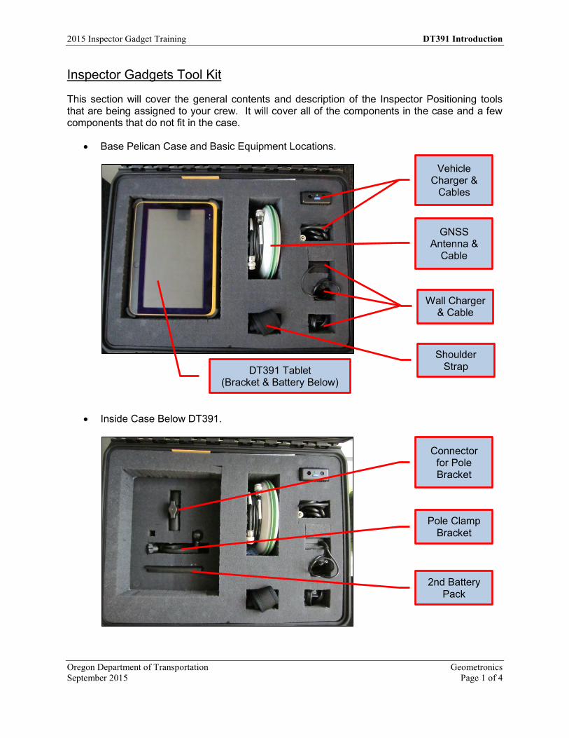
This section will cover the general contents and description of the Inspector Positioning tools that are being assigned to your crew. It will cover all of the components in the case and a few components that do not fit in the case.
Base Pelican Case and Basic Equipment Locations.
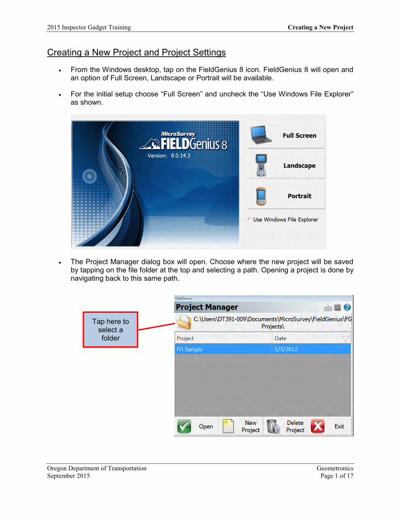
Inside Case Below DT391.
GNSS Antenna &
Cable
Vehicle Charger &
Cables
Wall Charger & Cable
Shoulder Strap DT391 Tablet
(Bracket & Battery Below)
Connector for Pole Bracket
Pole Clamp Bracket
2nd Battery Pack

OREGON DEPARTMENT
OF TRANSPORTATION
4040 Fairview
Industrial Dr. SE MS 4
Salem, OR 97302-1142
(503) 986-3103
Ron Singh, PLS
Chief of Surveys
(503) 986-3033
Kevin LaVerdure, PLS
Lead Surveyor
(503) 986-3017
Tim Weaver, PLS
Survey Support
(503) 986-3035
Chris Pucci, PLS
Const. Automation Surveyor
(503) 986-3542
Geoff Paull, LSI
Survey Crew Chief
(503) 986-3024
FieldGenius Create a New Project
Title Field Genius Create a New Project
Version 8.0 Date September 1, 2015 Author Chris Pucci
Overview This document will cover creating a new project and basic setup of FieldGenius 8.0.
2015 Inspector Gadget Training Creating a New Project
Oregon Department of Transportation Geometronics September 2015 Page 1 of 17
Creating a New Project and Project Settings
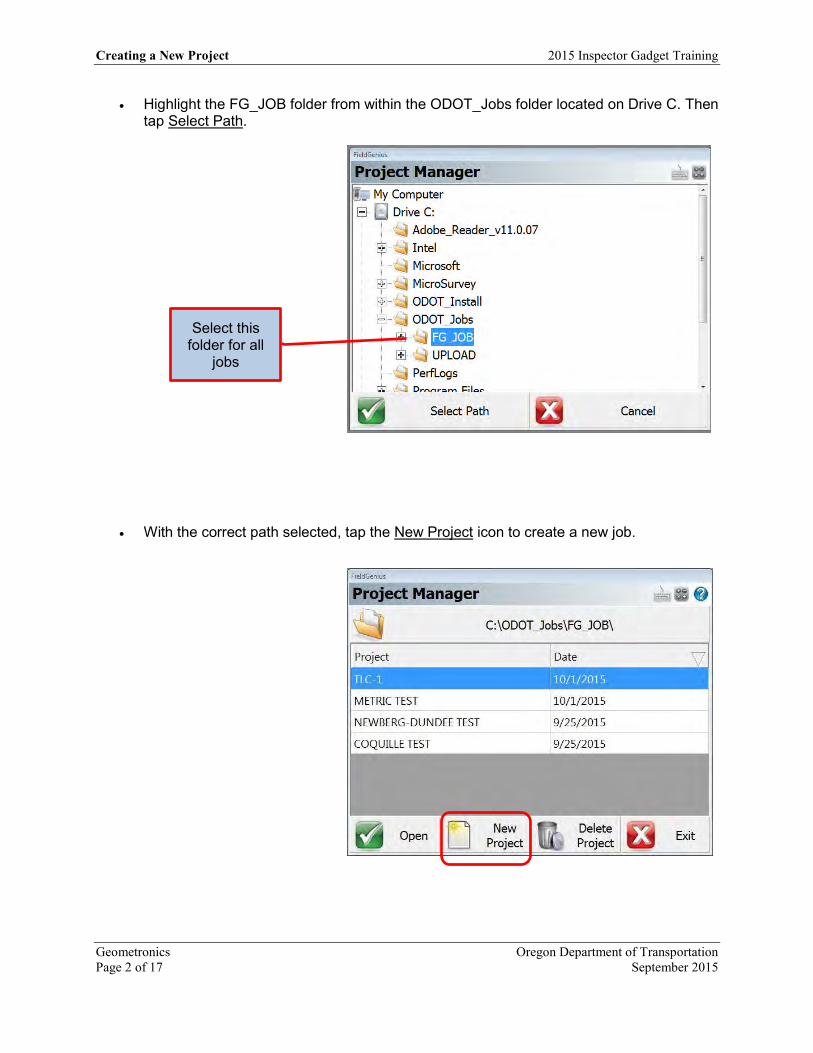
From the Windows desktop, tap on the FieldGenius 8 icon. FieldGenius 8 will open and an option of Full Screen, Landscape or Portrait will be available.
For the initial setup choose “Full Screen” and uncheck the “Use Windows File Explorer” as shown.
The Project Manager dialog box will open. Choose where the new project will be saved by tapping on the file folder at the top and selecting a path. Opening a project is done by navigating back to this same path.
Tap here to select a folder
Creating a New Project 2015 Inspector Gadget Training
Geometronics Oregon Department of Transportation Page 2 of 17 September 2015
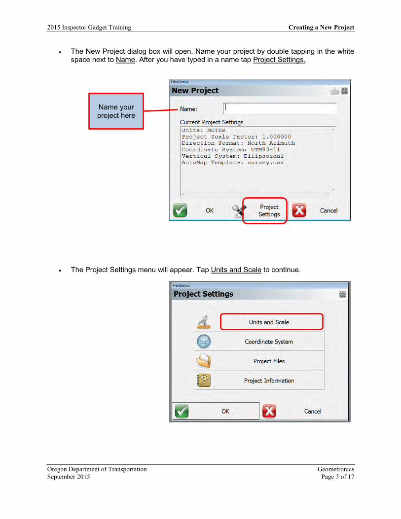
Highlight the FG_JOB folder from within the ODOT_Jobs folder located on Drive C. Then tap Select Path.
With the correct path selected, tap the New Project icon to create a new job.
Select this folder for all
jobs
2015 Inspector Gadget Training Creating a New Project
Oregon Department of Transportation Geometronics September 2015 Page 3 of 17
The New Project dialog box will open. Name your project by double tapping in the white space next to Name. After you have typed in a name tap Project Settings.
The Project Settings menu will appear. Tap Units and Scale to continue.
Name your project here
Creating a New Project 2015 Inspector Gadget Training
Geometronics Oregon Department of Transportation Page 4 of 17 September 2015
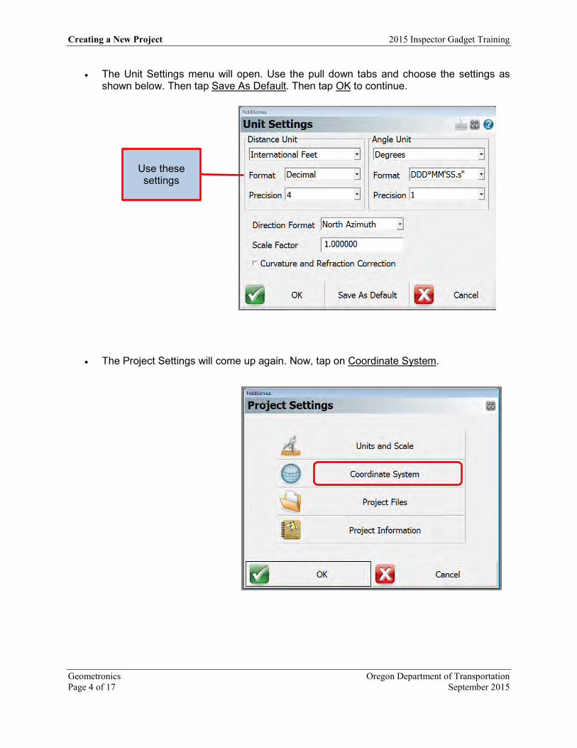
The Unit Settings menu will open. Use the pull down tabs and choose the settings as shown below. Then tap Save As Default. Then tap OK to continue.
The Project Settings will come up again. Now, tap on Coordinate System.
Use these settings
4 1
2015 Inspector Gadget Training Creating a New Project
Oregon Department of Transportation Geometronics September 2015 Page 5 of 17
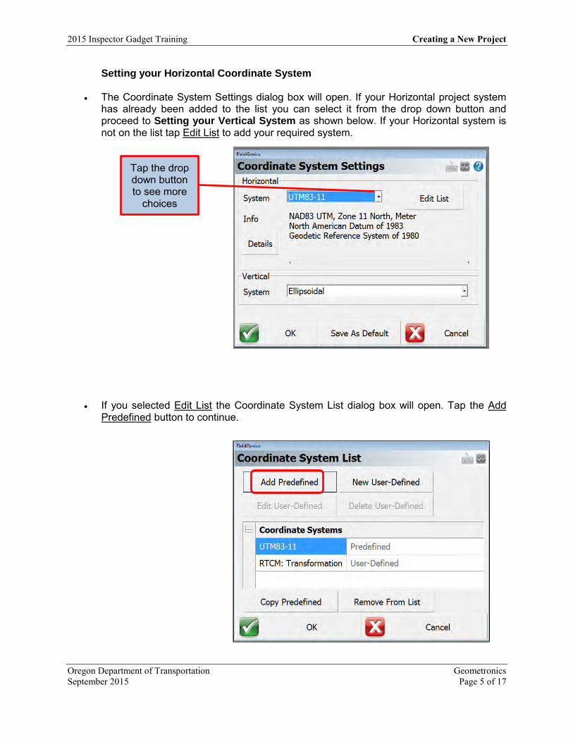
Setting your Horizontal Coordinate System
The Coordinate System Settings dialog box will open. If your Horizontal project system has already been added to the list you can select it from the drop down button and proceed to Setting your Vertical System as shown below. If your Horizontal system is not on the list tap Edit List to add your required system.
If you selected Edit List the Coordinate System List dialog box will open. Tap the Add Predefined button to continue.
Tap the drop down button to see more
choices

Creating a New Project 2015 Inspector Gadget Training
Geometronics Oregon Department of Transportation Page 6 of 17 September 2015
The Add Predefined menu will open. By Group choose “Other US Systems” and by System choose the OCRS coordinate system for your project. Then tap OK. At the Coordinate System List dialog box the new coordinate system will be shown. Tap OK again.
Back at the Coordinate System Settings menu change the Horizontal System to the chosen OCRS system using the drop down button. With your Horizontal system select proceed to Setting your Vertical System below.
Tap the drop down button to select your
system

2015 Inspector Gadget Training Creating a New Project
Oregon Department of Transportation Geometronics September 2015 Page 7 of 17
Setting you Vertical System
On the Coordinate System Settings menu change the Vertical System to “GEOID12A-1.bin”. Tap OK to continue.
The Project Settings dialog box will return. Now tap on the Project Files tab.

Creating a New Project 2015 Inspector Gadget Training
Geometronics Oregon Department of Transportation Page 8 of 17 September 2015
On the New Project Files menu uncheck the box next to Use Template and import ODOT-FG-CODE.csv by tapping the browse button to the right of the field.
From the browse menu navigate to “C:\ODOT_Install\MicroSurvey\ODOT-FG-CODE.csv” Tap Open File.
Tap the browse button to select the correct file

2015 Inspector Gadget Training Creating a New Project
Oregon Department of Transportation Geometronics September 2015 Page 9 of 17
With the correct ODOT file shown tap Continue.
Tap OK at the Project Settings menu to continue

Creating a New Project 2015 Inspector Gadget Training
Geometronics Oregon Department of Transportation Page 10 of 17 September 2015
The New Project menu will be displayed showning all of the settings you have selected. If they are correct Tap OK, if not go back to Project Settings to correct them.
The Instrument Selection menu will be displayed. Tap Close to continue with the project setup.

2015 Inspector Gadget Training Creating a New Project
Oregon Department of Transportation Geometronics September 2015 Page 11 of 17
Loading Construction Files
.xml files
Project files such as .csv and .txt need to be loaded onto the USB drive and uploaded to the tablet.
Project files such as .dtm and .alg need to be converted to .xml and then loaded onto the USB drive to be uploaded to the tablet. Copy the files to :..\ODOT_Jobs\UPLOAD
Insert the USB drive that contains the desired files to be loaded into the tablet.
Tap on the windows icon located on the bottom left of the tablet screen.
Tap on Computer to open Windows Explorer and navigate to C:\ODOT_Jobs\UPLOAD. At this location creating a new folder that is titled the same name as the project it is for is recommended.
Open another Windows Explorer and navigate to the inserted USB located under Devices with Removable Storage.
Either drag and drop the desired files or copy and paste from the USB (pictured right) to the C drive on the tablet (pictured left).

Creating a New Project 2015 Inspector Gadget Training
Geometronics Oregon Department of Transportation Page 12 of 17 September 2015
Open FieldGenius 8 by tapping the icon on the tablet’s desktop.
After tapping on Full Screen, Project Manager will open. Highlight the desired project and tap Open. Note: If needed, navigating to the desired project can be done by tapping the folder at the top.
Tap Continue when the Open Project Files dialog box opens.
For this tutorial tap Close when the Instrument Selection dialog box opens. Connecting to a GPS receiver will be covered in another section.
2015 Inspector Gadget Training Creating a New Project
Oregon Department of Transportation Geometronics September 2015 Page 13 of 17
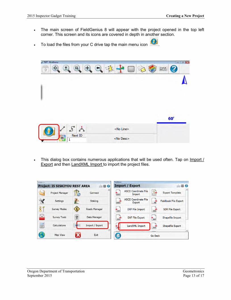
The main screen of FieldGenius 8 will appear with the project opened in the top left corner. This screen and its icons are covered in depth in another section.
To load the files from your C drive tap the main menu icon .
This dialog box contains numerous applications that will be used often. Tap on Import / Export and then LandXML Import to import the project files.
Creating a New Project 2015 Inspector Gadget Training
Geometronics Oregon Department of Transportation Page 14 of 17 September 2015
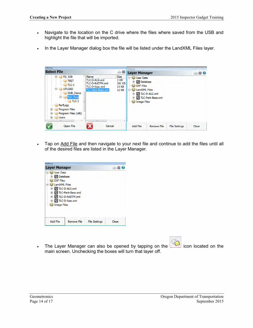
Navigate to the location on the C drive where the files where saved from the USB and highlight the file that will be imported.
In the Layer Manager dialog box the file will be listed under the LandXML Files layer.
Tap on Add File and then navigate to your next file and continue to add the files until all of the desired files are listed in the Layer Manager.
The Layer Manager can also be opened by tapping on the icon located on the main screen. Unchecking the boxes will turn that layer off.

2015 Inspector Gadget Training Creating a New Project
Oregon Department of Transportation Geometronics September 2015 Page 15 of 17
Imported surfaces can be viewed by tapping the icon on the main screen.
Check the surfaces that want to be viewed. Unchecking the boxes will turn that surface off.
The surface can now be viewed on the main screen’s map.

Creating a New Project 2015 Inspector Gadget Training
Geometronics Oregon Department of Transportation Page 16 of 17 September 2015
ASCII files
Loading text files such as control points can be loaded using a similar method. Navigate back to the Import / Export dialog box and tap on ASCII Coordinate File Import.
Tap on Browse for File in the Import Coordinate File dialog box.
Navigate to the desired file and tap on Preview File to view and check the delimitation.
Tap Open File and set the Import Coordinate File fields (above) appropriately.
Use these import
settings

2015 Inspector Gadget Training Creating a New Project
Oregon Department of Transportation Geometronics September 2015 Page 17 of 17
Points from the text file will appear on the main screen.
Coordinates can be checked by tapping the icon.
For more info and help see the FieldGenius Online help videos
http://helpdesk.microsurvey.com/index.php?/Knowledgebase/Article/View/149#GPS

OREGON DEPARTMENT
OF TRANSPORTATION
4040 Fairview
Industrial Dr. SE MS 4
Salem, OR 97302-1142
(503) 986-3103
Ron Singh, PLS
Chief of Surveys
(503) 986-3033
Kevin LaVerdure, PLS
Lead Surveyor
(503) 986-3017
Tim Weaver, PLS
Survey Support
(503) 986-3035
Chris Pucci, PLS
Const. Automation Surveyor
(503) 986-3542
Geoff Paull, LSI
Survey Crew Chief
(503) 986-3024
Inspector Tablet GNSS/ORGN Setup
Title GNSS/ORGN Setup FieldGenius 8.1 Model DT391-P303 Date November 6, 2015 Author Chris Pucci
Overview This document will give instructions for setting up the GNSS and connecting the tablet to the ORGN.
2015 Inspector Gadget Training GNSS/ORGN Setup
Oregon Department of Transportation Geometronics September 2015 Page 1 of 9
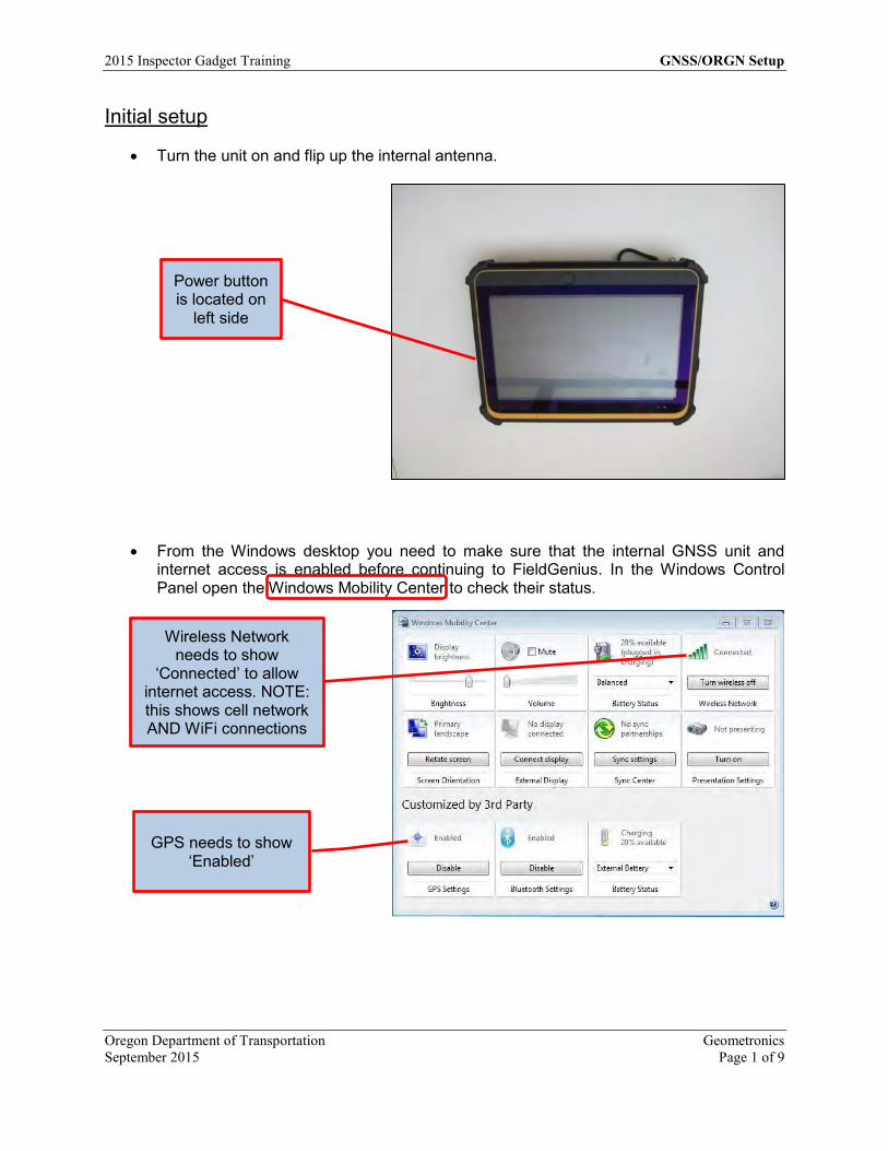
Initial setup
Turn the unit on and flip up the internal antenna.
From the Windows desktop you need to make sure that the internal GNSS unit and internet access is enabled before continuing to FieldGenius. In the Windows Control Panel open the Windows Mobility Center to check their status.
Power button is located on
left side
Wireless Network needs to show
‘Connected’ to allow internet access. NOTE: this shows cell network AND WiFi connections
GPS needs to show ‘Enabled’

GNSS/ORGN Setup 2015 Inspector Gadget Training
Geometronics Oregon Department of Transportation Page 2 of 9 September 2015
FieldGenius GNSS setup
From the Windows desktop tap on the FieldGenius 8 icon. FieldGenius will open.
You can get to the Instrument Selection menu in many ways. Either as a step in setting up a job or if you did not connect to an instrument when setting up the job, Connect will be an option on the Main Menu screen. Tap Connect to select an instrument.
From the Instrument Selection screen, select “GNSS Rover” and select the HEMI P303 ORGN from the drop down in the Instrument Profile menu. Tap Connect to start the HEMI P303 ORGN Connection.
If you have not selected an instrument it will be an option on the Main
Menu
Select GNSS Rover
HEMI P303 is the internal GNSS unit.
HEMI P303 ORGN
2015 Inspector Gadget Training GNSS/ORGN Setup
Oregon Department of Transportation Geometronics September 2015 Page 3 of 9
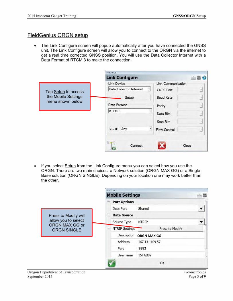
FieldGenius ORGN setup
The Link Configure screen will popup automatically after you have connected the GNSS unit. The Link Configure screen will allow you to connect to the ORGN via the internet to get a real time corrected GNSS position. You will use the Data Collector Internet with a Data Format of RTCM 3 to make the connection.
If you select Setup from the Link Configure menu you can select how you use the ORGN. There are two main choices, a Network solution (ORGN MAX GG) or a Single Base solution (ORGN SINGLE). Depending on your location one may work better than the other.
Tap Setup to access the Mobile Settings menu shown below
Press to Modify will allow you to select ORGN MAX GG or
ORGN SINGLE
9882
ORGN MAX GG

GNSS/ORGN Setup 2015 Inspector Gadget Training
Geometronics Oregon Department of Transportation Page 4 of 9 September 2015
If you Press to Modify from the Mobile Settings menu the NTRIP Casters menu will popup. This is where you select the type of solution that will be used.
The Mobile Settings menu will return and if your selection is listed correctly tap OK to
continue. The Link Configure screen will then popup.
Highlight your choice and tap Select
Tap Connect to establish an internet connection with the
ORGN
9882
9882
ORGN MAX GG
2015 Inspector Gadget Training GNSS/ORGN Setup
Oregon Department of Transportation Geometronics September 2015 Page 5 of 9
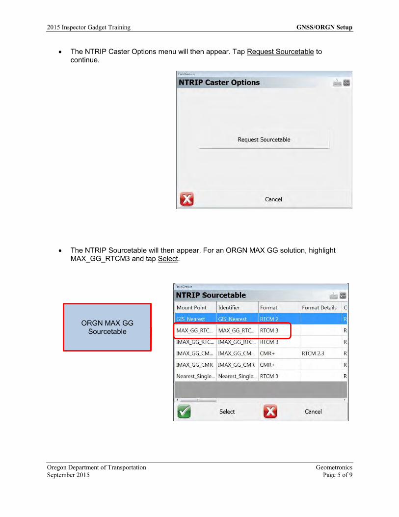
The NTRIP Caster Options menu will then appear. Tap Request Sourcetable to continue.
The NTRIP Sourcetable will then appear. For an ORGN MAX GG solution, highlight
MAX_GG_RTCM3 and tap Select.
ORGN MAX GG Sourcetable
GNSS/ORGN Setup 2015 Inspector Gadget Training
Geometronics Oregon Department of Transportation Page 6 of 9 September 2015
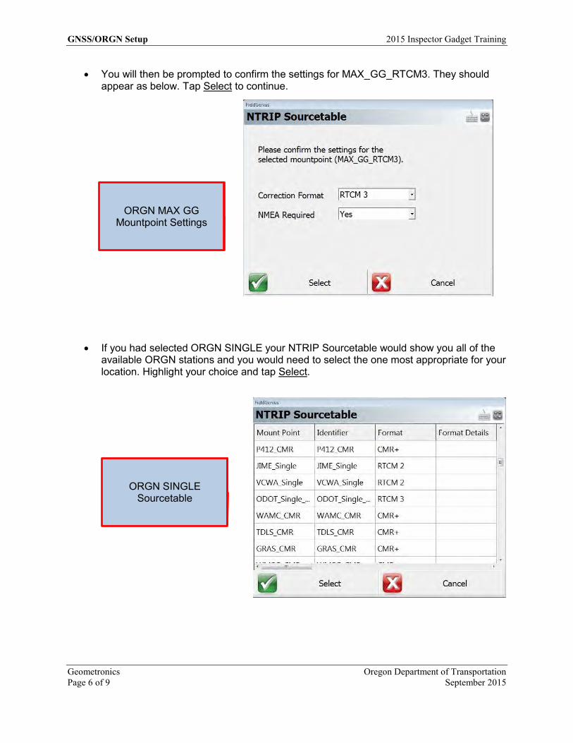
You will then be prompted to confirm the settings for MAX_GG_RTCM3. They should appear as below. Tap Select to continue.
If you had selected ORGN SINGLE your NTRIP Sourcetable would show you all of the available ORGN stations and you would need to select the one most appropriate for your location. Highlight your choice and tap Select.
ORGN SINGLE Sourcetable
ORGN MAX GG Mountpoint Settings

2015 Inspector Gadget Training GNSS/ORGN Setup
Oregon Department of Transportation Geometronics September 2015 Page 7 of 9
The ORGN SINGLE settings are slightly different, NMEA is not required. Tap Select to continue.
You should now be connected. If you are outside and receiving enough GNSS signals you should have an RTK FIXED solution.
ORGN SINGLE Mountpoint Settings
Icon showing you have an RTK Fixed solution
Satellite icon

GNSS/ORGN Setup 2015 Inspector Gadget Training
Geometronics Oregon Department of Transportation Page 8 of 9 September 2015
Tapping the Satellite icon will bring up the Satellite Plot menu showing how many satellites are being tracked. Only GPS satellites are counted on the small icon, but all satellites are shown on the Plot screen.
Tapping the Antenna Height icon will bring up the Antenna Height menu allowing you to change your antenna height which is the height the GNSS antenna is above the point you want to measure. It is critical to enter the correct antenna height if you wish to get an accurate vertical reading.
If you are using the P303 internal antenna, the
Measured Height is how far above the ground you are
holding the tablet
Filled circles are satellites locked and used. Empty
circles are tracked but not used in the solution.

2015 Inspector Gadget Training GNSS/ORGN Setup
Oregon Department of Transportation Geometronics September 2015 Page 9 of 9
If you have attached the external Leica AS10 antenna and mounted it to the fixed length rod you need to change the antenna model and height to get correct readings. You do not need to make any other changes in the unit. It automatically switches to the external antenna when the cable is connected.
Once you have everything setup and you are working in a job you will not need to go
through all of the steps each time you turn on the unit. After starting FieldGenius and selecting a job you will be prompted with the Reconnect menu. You can tap Reconnect and it will connect the GNSS unit and jump you to the Link Configure menu where you can tap Connect to use the ORGN settings from the previous session.
Select User Defined for the Model, 6.562’ for the Measured Height and set the ARP to APC offset to
58.3mm
Reconnect using the previous settings
OREGON DEPARTMENT
OF TRANSPORTATION
4040 Fairview
Industrial Dr. SE MS 4
Salem, OR 97302-1142
(503) 986-3103
Ron Singh, PLS
Chief of Surveys
(503) 986-3033
Kevin LaVerdure, PLS
Lead Surveyor
(503) 986-3017
Tim Weaver, PLS
Survey Support
(503) 986-3035
Chris Pucci, PLS
Const. Automation Surveyor
(503) 986-3542
Geoff Paull, LSI
Survey Crew Chief
(503) 986-3024
Inspector Tablet GNSS GS14 Radio Setup
Title Inspector tablet GNSS GS14 Radio Setup
Version 8.0 Model DT391 w/GS14 Date October 5, 2015 Author Chris Pucci
Overview This document will give instructions for setting up the Leica GS14 as an RTK rover and using a local radio base station.

2015 Inspector Gadget Training GNSS GS14 Radio Setup
Oregon Department of Transportation Geometronics September 2015 Page 1 of 8
Initial setup
From the Windows desktop you need to make sure that Bluetooth is enabled and before continuing to FieldGenius. In the Windows Control Panel open the Windows Mobility Center to check on the Bluetooth status.
If you tap the Bluetooth Icon in the lower right hand portion of the Windows Main screen it will allow you to “Add a Device”. If you have the GS14 unit turned on Windows should show it in the list of devices. Highlight the device and tap Next. Note: Make sure other Bluetooth devices are deactivated or move to an area without other Bluetooth sources.
Bluetooth needs to show Enabled
You can disable the internal GPS to conserve power
This is the serial number of the GS14
unit

GNSS GS14 Radio Setup 2015 Inspector Gadget Training
Geometronics Oregon Department of Transportation Page 2 of 8 September 2015
Windows will ask you to select a pairing option. Select “Pair without using a code”.
When the GS14 has been added it will show the following screen. Select Close.
Use Pair without using a code

2015 Inspector Gadget Training GNSS GS14 Radio Setup
Oregon Department of Transportation Geometronics September 2015 Page 3 of 8
FieldGenius GNSS setup
From the Windows desktop tap on the FieldGenius 8 icon. FieldGenius 8 will open. Open your job as normal and when prompted to Reconnect, tap Select Instrument
GNSS Rover setup
The first time you setup a GS14 unit as a Rover you will need to follow these steps. From the Select Instrument screen pick “GNSS Rover” as your instrument type and tap Add to create a profile for your unit.
Select GNSS Rover
GNSS GS14 Radio Setup 2015 Inspector Gadget Training
Geometronics Oregon Department of Transportation Page 4 of 8 September 2015
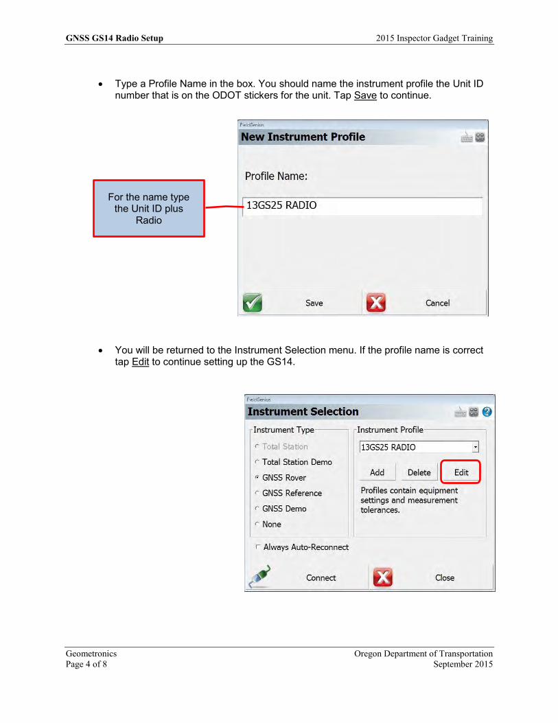
Type a Profile Name in the box. You should name the instrument profile the Unit ID
number that is on the ODOT stickers for the unit. Tap Save to continue.
You will be returned to the Instrument Selection menu. If the profile name is correct tap Edit to continue setting up the GS14.
For the name type the Unit ID plus
Radio

2015 Inspector Gadget Training GNSS GS14 Radio Setup
Oregon Department of Transportation Geometronics September 2015 Page 5 of 8
With the GNSS Profile menu displayed tap the Model and Communication button to set the GS14 rover.
From the Model and Communication menu, set Make to Leica, Model to GS14, Port to Bluetooth. Tap Bluetooth Device List to see a list of available units.
Use these settings for a GS14
Tap here to see the Bluetooth units that
you can choose from

GNSS GS14 Radio Setup 2015 Inspector Gadget Training
Geometronics Oregon Department of Transportation Page 6 of 8 September 2015
From the Bluetooth Device List highlight the correct unit and tap Close to continue.
If all the settings are displayed correctly, tap Connect. You should now be connected to the GS14 unit.
2015 Inspector Gadget Training GNSS GS14 Radio Setup
Oregon Department of Transportation Geometronics September 2015 Page 7 of 8
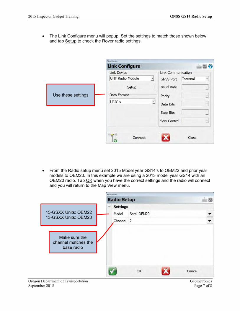
The Link Configure menu will popup. Set the settings to match those shown below
and tap Setup to check the Rover radio settings.
From the Radio setup menu set 2015 Model year GS14’s to OEM22 and prior year models to OEM20. In this example we are using a 2013 model year GS14 with an OEM20 radio. Tap OK when you have the correct settings and the radio will connect and you will return to the Map View menu.
Use these settings LEICA
15-GSXX Units: OEM22 13-GSXX Units: OEM20
Make sure the channel matches the
base radio
GNSS GS14 Radio Setup 2015 Inspector Gadget Training
Geometronics Oregon Department of Transportation Page 8 of 8 September 2015
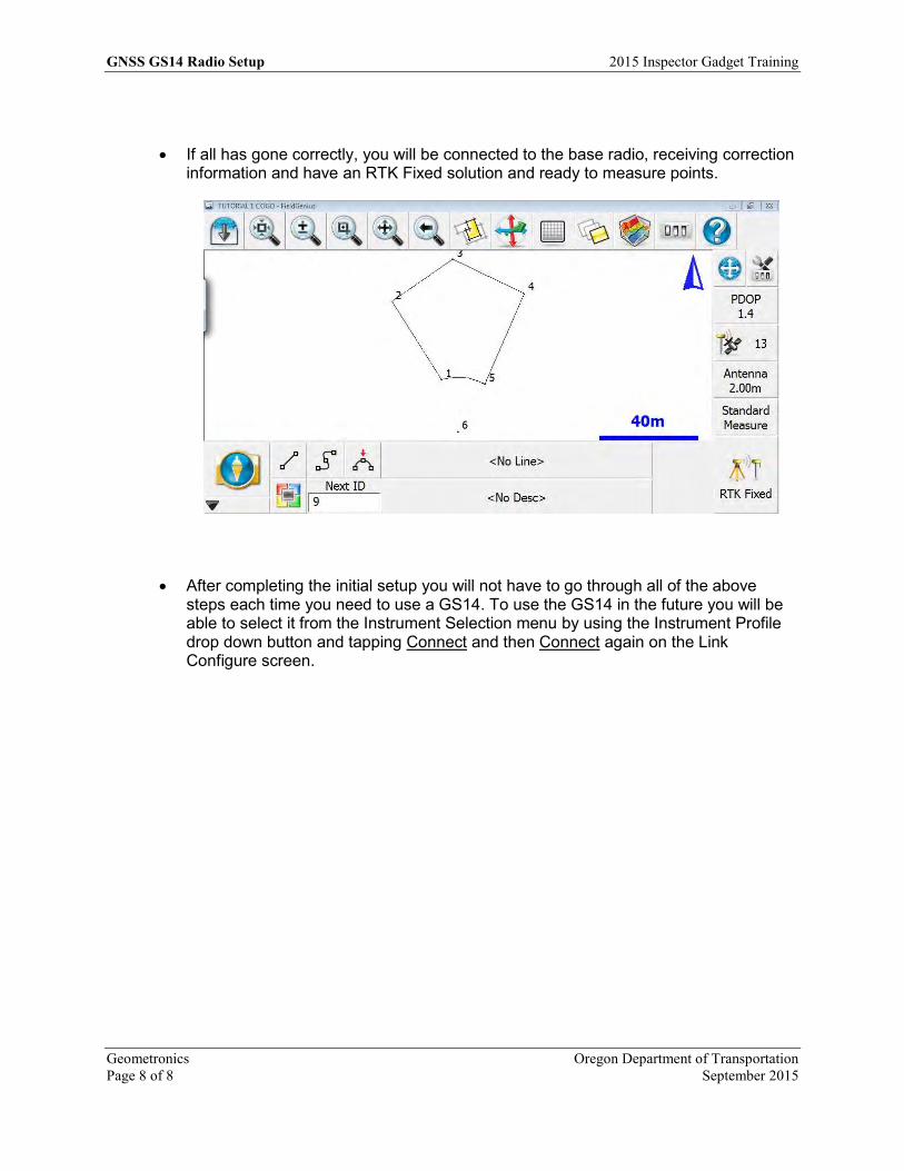
If all has gone correctly, you will be connected to the base radio, receiving correction information and have an RTK Fixed solution and ready to measure points.
After completing the initial setup you will not have to go through all of the above steps each time you need to use a GS14. To use the GS14 in the future you will be able to select it from the Instrument Selection menu by using the Instrument Profile drop down button and tapping Connect and then Connect again on the Link Configure screen.
OREGON DEPARTMENT
OF TRANSPORTATION
4040 Fairview
Industrial Dr. SE MS 4
Salem, OR 97302-1142
(503) 986-3103
Ron Singh, PLS
Chief of Surveys
(503) 986-3033
Kevin LaVerdure, PLS
Lead Surveyor
(503) 986-3017
Tim Weaver, PLS
Survey Support
(503) 986-3035
Chris Pucci, PLS
Const. Automation Surveyor
(503) 986-3542
Geoff Paull, LSI
Survey Crew Chief
(503) 986-3024
FieldGenius Overview Map View
Title FieldGenius Overview Map View Version 8.0 Date September 3, 2015 Author Chris Pucci
Overview This document will cover the Map View screen in FieldGenius 8.0.

2015 Inspector Gadget Training Map View Screen
Oregon Department of Transportation Geometronics September 2015 Page 1 of 3
Map View Screen Overview
For FieldGenius the map view is the main screen for positioning tasks.
Major Button
Main Menu, Will open the Main Menu which contains all the settings, tasks and information
Display Toolbar Buttons (Top Bar)
Opens or closes the Observation Toolbar (Lots of tasks use this window)
Zoom Extents (Will show the full map)
Dynamic Zoom
Map View Screen 2015 Inspector Gadget Training
Geometronics Oregon Department of Transportation Page 2 of 3 September 2015
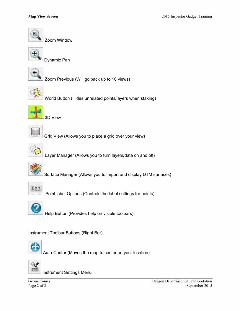
Zoom Window
Dynamic Pan
Zoom Previous (Will go back up to 10 views)
World Button (Hides unrelated points/layers when staking)
3D View
Grid View (Allows you to place a grid over your view)
Layer Manager (Allows you to turn layers/data on and off)
Surface Manager (Allows you to import and display DTM surfaces)
Point label Options (Controls the label settings for points)
Help Button (Provides help on visible toolbars)
Instrument Toolbar Buttons (Right Bar)
Auto-Center (Moves the map to center on your location)
Instrument Settings Menu

2015 Inspector Gadget Training Map View Screen
Oregon Department of Transportation Geometronics September 2015 Page 3 of 3
OR DOP Values or SD/Point Quality Value
Cycles through PDOP, HDOP, VDOP and SD Only shows a number when you have a sensor connected
OR Satellite Plot/List
Antenna menu (Allows you to select which antenna and set the height values)
Measurement Modes menu (Allows you to select the type of measurement)
OR Measure Button / Solution Type, this button will take a shot/position and shows the current solution.
Topo Toolbar Buttons (Bottom Bar)
Draw line Active line type description
Draw best fit curved line
Draw three point arc
Point Database Active point description
Next available point ID

OREGON DEPARTMENT
OF TRANSPORTATION
4040 Fairview
Industrial Dr. SE MS 4
Salem, OR 97302-1142
(503) 986-3103
Ron Singh, PLS
Chief of Surveys
(503) 986-3033
Kevin LaVerdure, PLS
Lead Surveyor
(503) 986-3017
Tim Weaver, PLS
Survey Support
(503) 986-3035
Chris Pucci, PLS
Const. Automation Surveyor
(503) 986-3542
Geoff Paull, LSI
Survey Crew Chief
(503) 986-3024
FieldGenius Data Collection
Title FieldGenius Data Collection
Info Inspector Tablet Version 8.1 Date November 6, 2015 Author Chris Pucci
Overview This document will cover basic data collection using FieldGenius 8.0.

2015 Inspector Gadget Training Data Collection
Oregon Department of Transportation Geometronics September 2015 Page 1 of 7
Data Collection
FieldGenius 8.0 has virtually unlimited features for collecting field data. This guide will cover some of the features that may be the most useful.
Most survey data begins with points. You need points to make lines, curves, arcs, etc.
To collect a point in FieldGenius you should have an RTK Fixed solution, tap the RTK Fixed icon and hold the sensor still until the shot is complete. The GNSS Measurement screen will show you a count down and prompt you to Store Position when a solution has been computed.
Tap Store Position to
collect the point
Data Collection 2015 Inspector Gadget Training
Geometronics Oregon Department of Transportation Page 2 of 7 September 2015
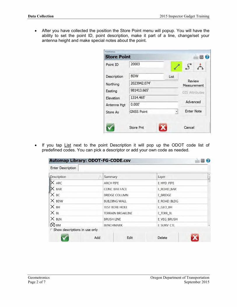
After you have collected the position the Store Point menu will popup. You will have the ability to set the point ID, point description, make it part of a line, change/set your antenna height and make special notes about the point.
If you tap List next to the point Description it will pop up the ODOT code list of
predefined codes. You can pick a descriptor or add your own code as needed.
2015 Inspector Gadget Training Data Collection
Oregon Department of Transportation Geometronics September 2015 Page 3 of 7
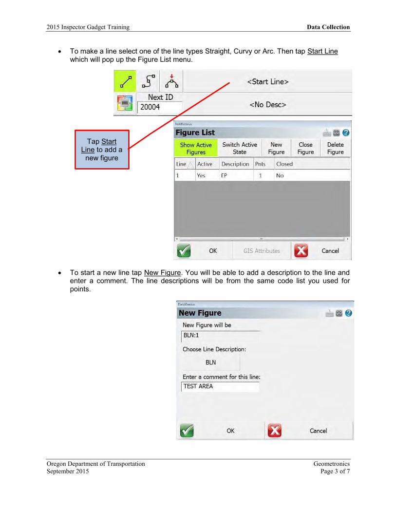
To make a line select one of the line types Straight, Curvy or Arc. Then tap Start Line which will pop up the Figure List menu.
To start a new line tap New Figure. You will be able to add a description to the line and
enter a comment. The line descriptions will be from the same code list you used for points.
Tap Start Line to add a
new figure
Data Collection 2015 Inspector Gadget Training
Geometronics Oregon Department of Transportation Page 4 of 7 September 2015
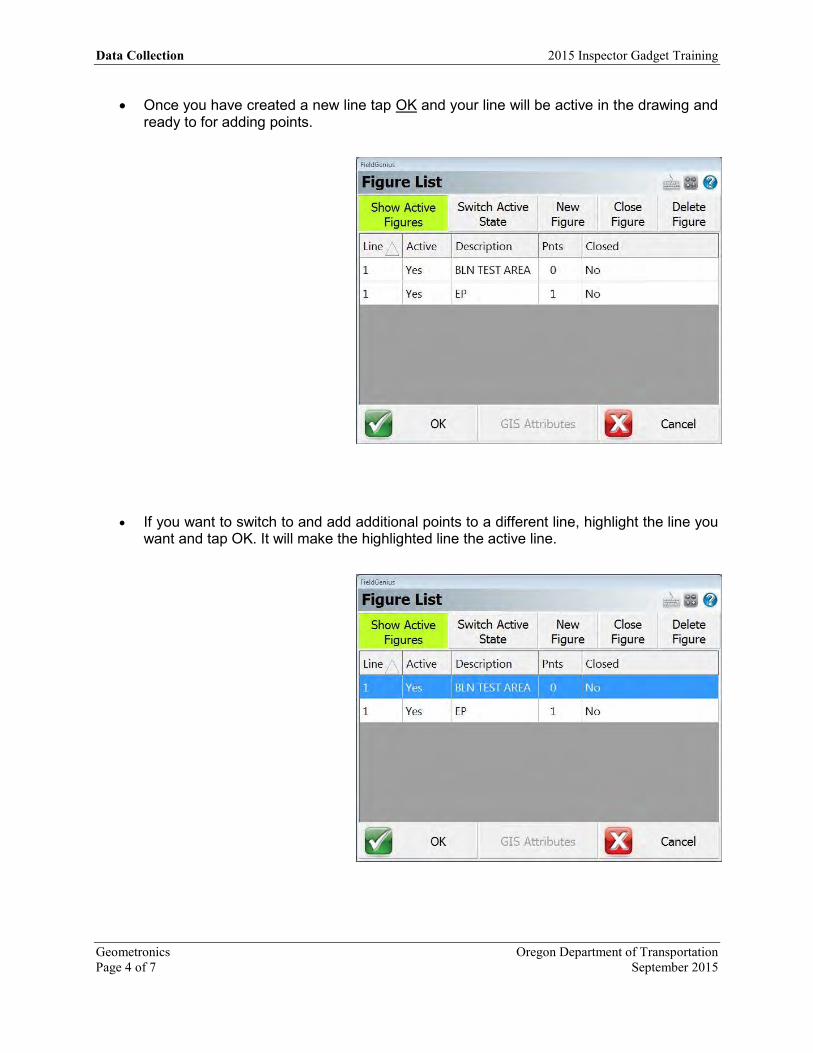
Once you have created a new line tap OK and your line will be active in the drawing and ready to for adding points.
If you want to switch to and add additional points to a different line, highlight the line you want and tap OK. It will make the highlighted line the active line.

2015 Inspector Gadget Training Data Collection
Oregon Department of Transportation Geometronics September 2015 Page 5 of 7
As you start collecting points by tapping the RTK Fixed icon, the points you collect will automatically make a line.
Once you have made a line you can work with it. If you pick a line by tapping one of the segments, the Line Toolbar will open.
Line Tools buttons.
Line Mode Active Line
Active Description
Line Toolbar

Data Collection 2015 Inspector Gadget Training
Geometronics Oregon Department of Transportation Page 6 of 7 September 2015
Set line to Active in the Line List Ends a figure
Reverses the direction of a line Adds points along a line
Deletes a segment from a line Deletes an entire line
Closes a line (To get an area a line must be closed)
Opens the Active Line List Opens the Draw Tool menu
Changes a line from straight to curvy or vice-versa
Opens the Offset Tool Opens the Stake Line Menu
Displays the lines info Closes the Line Tool Bar
To calculate the area created by a line. Store all of the exterior points as one line. When you are finished select the line by tapping any segment, then tap the Close Line button. It will prompt you to make a selection. Choose Yes. Close the Line Tools bar by tapping the red “X”. Reselect the line and tap the Info “i” and your area will be displayed.
Area of the Figure
2015 Inspector Gadget Training Data Collection
Oregon Department of Transportation Geometronics September 2015 Page 7 of 7
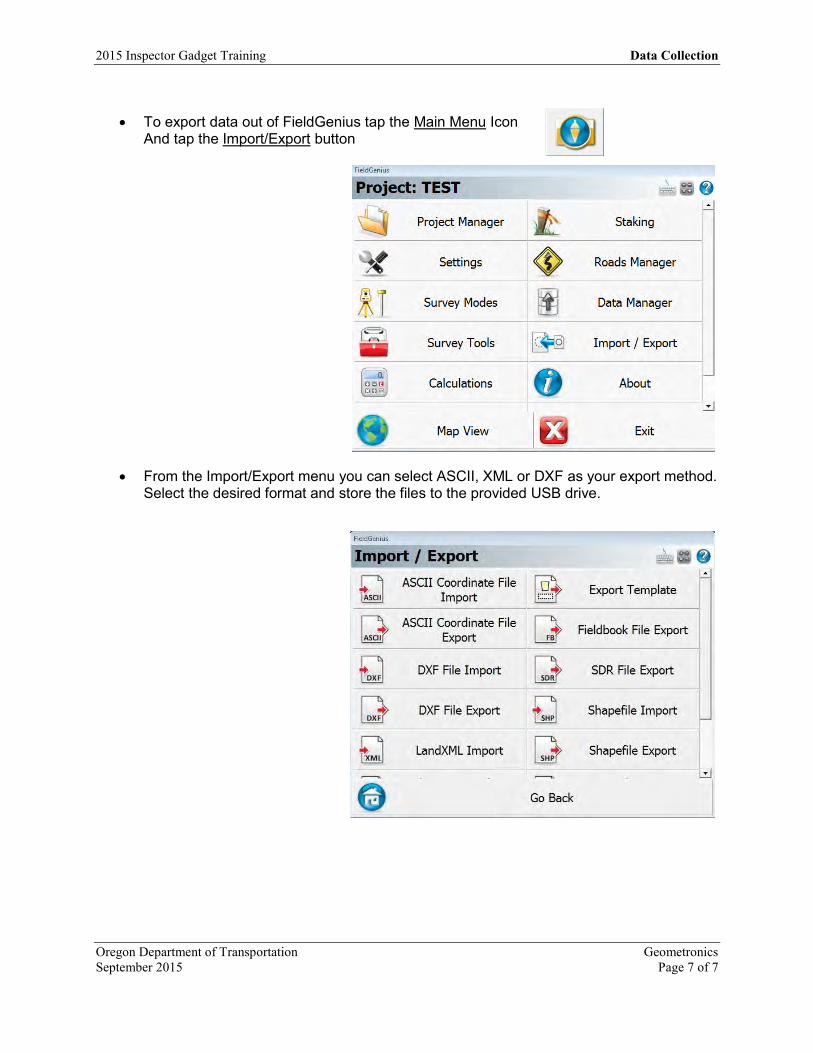
To export data out of FieldGenius tap the Main Menu Icon
And tap the Import/Export button
From the Import/Export menu you can select ASCII, XML or DXF as your export method. Select the desired format and store the files to the provided USB drive.

OREGON DEPARTMENT
OF TRANSPORTATION
4040 Fairview
Industrial Dr. SE MS 4
Salem, OR 97302-1142
(503) 986-3103
Ron Singh, PLS
Chief of Surveys
(503) 986-3033
Kevin LaVerdure, PLS
Lead Surveyor
(503) 986-3017
Tim Weaver, PLS
Survey Support
(503) 986-3035
Chris Pucci, PLS
Const. Automation Surveyor
(503) 986-3542
Geoff Paull, LSI
Survey Crew Chief
(503) 986-3024
FieldGenius Staking
Title FieldGenius Staking Info Inspector Tablet Version 8.1 Date September 8, 2015 Author Chris Pucci
Overview This document will cover basic stake out using FieldGenius 8.0.
2015 Inspector Gadget Training Staking
Oregon Department of Transportation Geometronics September 2015 Page 1 of 11
Point Staking
FieldGenius 8.0 can be used to stake out locations and features from alignments, surface models and coordinate files once the correct files have been loaded for your job.
Open or Create your project in FieldGenius and connect to the sensor.
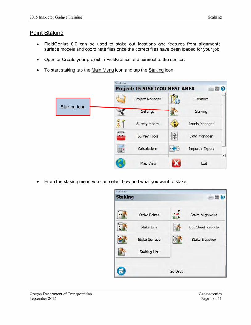
To start staking tap the Main Menu icon and tap the Staking icon.
From the staking menu you can select how and what you want to stake.
Staking Icon
Staking 2015 Inspector Gadget Training
Geometronics Oregon Department of Transportation Page 2 of 11 September 2015
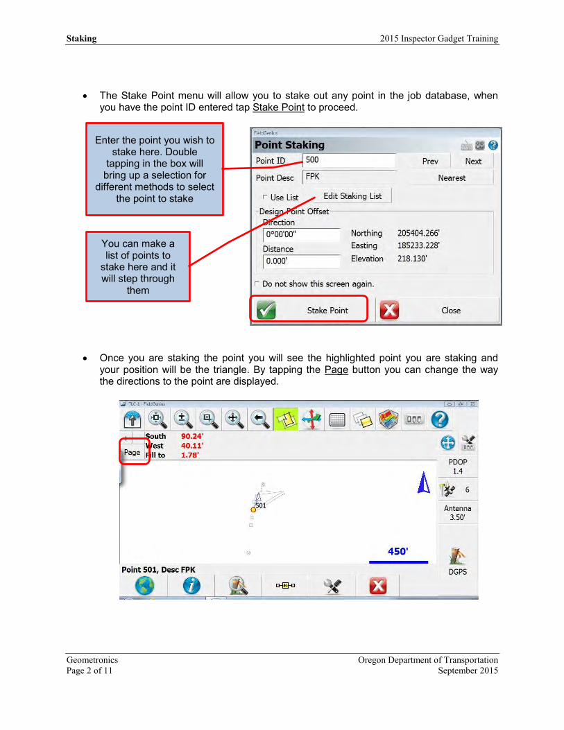
The Stake Point menu will allow you to stake out any point in the job database, when you have the point ID entered tap Stake Point to proceed.
Once you are staking the point you will see the highlighted point you are staking and your position will be the triangle. By tapping the Page button you can change the way the directions to the point are displayed.
Enter the point you wish to stake here. Double
tapping in the box will bring up a selection for
different methods to select the point to stake
You can make a list of points to
stake here and it will step through
them
2015 Inspector Gadget Training Staking
Oregon Department of Transportation Geometronics September 2015 Page 3 of 11
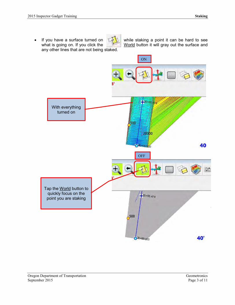
If you have a surface turned on while staking a point it can be hard to see what is going on. If you click the World button it will gray out the surface and any other lines that are not being staked.
With everything turned on
Tap the World button to quickly focus on the point you are staking
ON
OFF

Staking 2015 Inspector Gadget Training
Geometronics Oregon Department of Transportation Page 4 of 11 September 2015
After navigating to the point, you will be able to see how close you are. If you want to re-
measure the point and store the information tap the RTK Fixed icon just like you are collecting data.
If you aren’t using the external antenna, the constructed point is not exactly per plan or the point has been disturbed (moved) you will get a tolerance exceeded error. You can still tap Save Point and Raw Data to collect the point.
Tap here to save point
Distance from calculated point
to collected point
2015 Inspector Gadget Training Staking
Oregon Department of Transportation Geometronics September 2015 Page 5 of 11
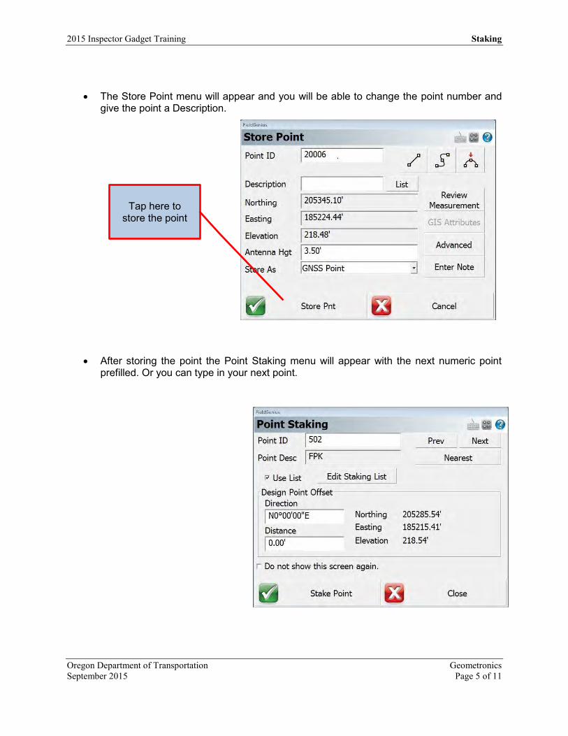
The Store Point menu will appear and you will be able to change the point number and give the point a Description.
After storing the point the Point Staking menu will appear with the next numeric point prefilled. Or you can type in your next point.
Tap here to store the point

Staking 2015 Inspector Gadget Training
Geometronics Oregon Department of Transportation Page 6 of 11 September 2015
Surface Staking
If you select Stake Surface from the Staking menu you will be prompted to select a surface to stake to. The surface must be visible/active before you can select it for staking.
The Surface Manager menu will allow you to turn surface on and off. Select the surface you want to stake.
No visible surfaces. Tap Surface
Manager to select a surface
Select your surface and tap Close to
proceed

2015 Inspector Gadget Training Staking
Oregon Department of Transportation Geometronics September 2015 Page 7 of 11
You should now have a surface listed in your Select Surface menu. Tap Continue to proceed.
You should now have a surface in your Map View and details about your position. If you are outside the limits of the surface model, it will let you know.
Current Position

Staking 2015 Inspector Gadget Training
Geometronics Oregon Department of Transportation Page 8 of 11 September 2015
Once you are within the surface limits you will be given a cut or fill to the design elevation at your point. Remember your elevation is based on the antenna height.
Alignment Staking
To stake an alignment select Stake Alignment from the Staking menu. The Road Manager menu will popup. Highlight the alignment you want to stake and tap Manage Road.
Note: The Alignment or cross section xml must
be loaded into your project before you can
stake it.

2015 Inspector Gadget Training Staking
Oregon Department of Transportation Geometronics September 2015 Page 9 of 11
Tap Stake Road to continue.
The Stake Alignment menu will popup. You can change the Station, Offset and Elevation you wish to stake. After making your selection tap Stake Offset to begin staking.
The centerline at Station 20+00 will
be staked
FieldGenius will stake using both horizontal and vertical
information. If you need to use templates, cross sections or a surface to control the vertical
design, make the proper selection in this detail screen.
Once you have made the proper selection tap Stake Road to
continue.
Staking 2015 Inspector Gadget Training
Geometronics Oregon Department of Transportation Page 10 of 11 September 2015
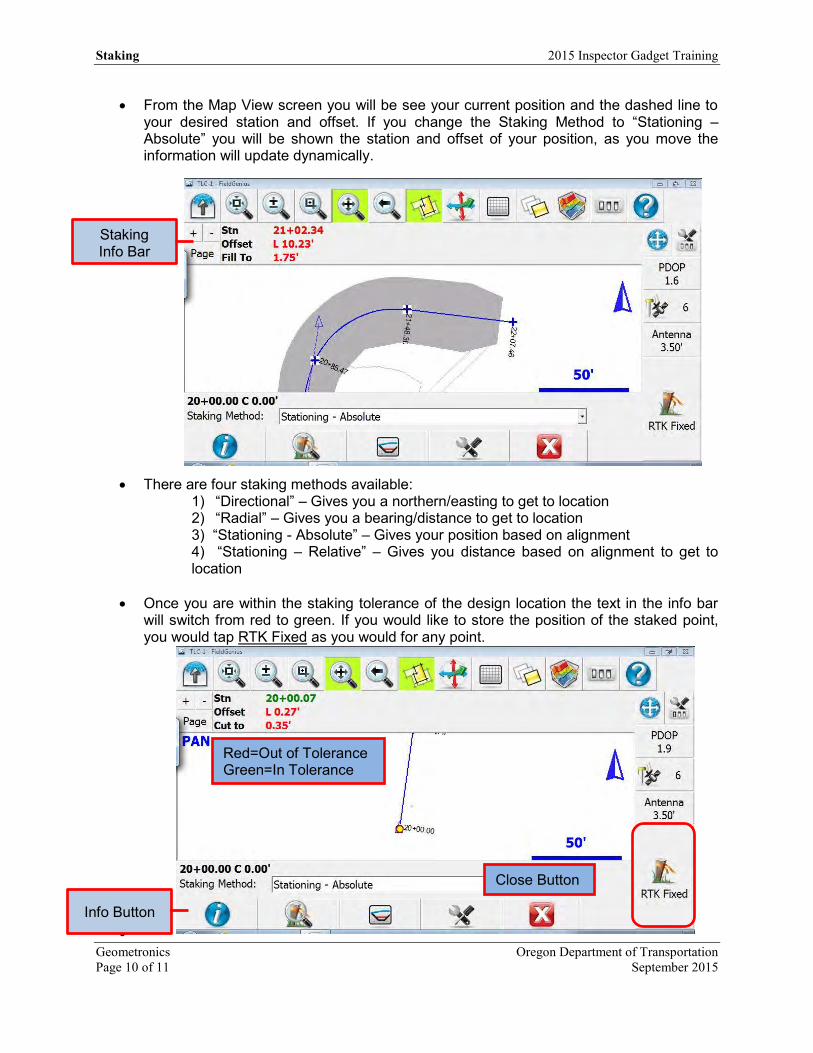
From the Map View screen you will be see your current position and the dashed line to your desired station and offset. If you change the Staking Method to “Stationing – Absolute” you will be shown the station and offset of your position, as you move the information will update dynamically.
There are four staking methods available: 1) “Directional” – Gives you a northern/easting to get to location 2) “Radial” – Gives you a bearing/distance to get to location 3) “Stationing - Absolute” – Gives your position based on alignment 4) “Stationing – Relative” – Gives you distance based on alignment to get to location
Once you are within the staking tolerance of the design location the text in the info bar will switch from red to green. If you would like to store the position of the staked point, you would tap RTK Fixed as you would for any point.
Staking Info Bar
Info Button
Red=Out of Tolerance Green=In Tolerance
Close Button
2015 Inspector Gadget Training Staking
Oregon Department of Transportation Geometronics September 2015 Page 11 of 11
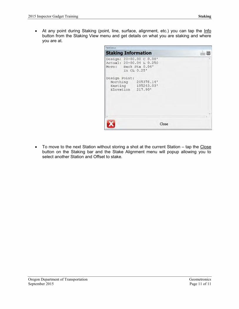
At any point during Staking (point, line, surface, alignment, etc.) you can tap the Info button from the Staking View menu and get details on what you are staking and where you are at.
To move to the next Station without storing a shot at the current Station – tap the Close button on the Staking bar and the Stake Alignment menu will popup allowing you to select another Station and Offset to stake.

OREGON DEPARTMENT
OF TRANSPORTATION
4040 Fairview
Industrial Dr. SE MS 4
Salem, OR 97302-1142
(503) 986-3103
Ron Singh, PLS
Chief of Surveys
(503) 986-3033
Kevin LaVerdure, PLS
Lead Surveyor
(503) 986-3017
Tim Weaver, PLS
Survey Support
(503) 986-3035
Chris Pucci, PLS
Const. Automation Surveyor
(503) 986-3542
Geoff Paull, LSI
Survey Crew Chief
(503) 986-3024
Working with DXF files in FieldGenius
Title Working with DXF files Version FieldGenius 8.1 Date November 4, 2015 Author Chris Pucci
Overview This document will cover using DXF files inside of FieldGenius.
2015 Inspector Gadget Training Working with DXF files
Oregon Department of Transportation Geometronics November 2015 Page 1 of 5
Working with DXF Files
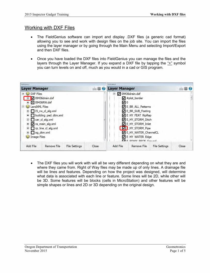
The FieldGenius software can import and display .DXF files (a generic cad format) allowing you to see and work with design files on the job site. You can import the files using the layer manager or by going through the Main Menu and selecting Import/Export and then DXF files.
Once you have loaded the DXF files into FieldGenius you can manage the files and the layers through the Layer Manager. If you expand a DXF file by tapping the “+” symbol you can turn levels on and off, much as you would in a cad or GIS program.
The DXF files you will work with will all be very different depending on what they are and where they came from. Right of Way files may be made up of only lines. A drainage file will be lines and features. Depending on how the project was designed, will determine what data is associated with each line or feature. Some lines will be 2D, while other will be 3D. Some features will be blocks (cells in MicroStation) and other features will be simple shapes or lines and 2D or 3D depending on the original design.

Working with DXF files 2015 Inspector Gadget Training
Geometronics Oregon Department of Transportation Page 2 of 5 November 2015
In the project below we have zoomed in on a section of a drainage design DXF and can see round manholes and square inlet structures with pipes connecting them.
If you select a manhole by tapping it, you will get a selection specific menu bar along the bottom of the screen. If you would like to make a point in the project that you can stake to, tap the Store DXF Insertion Point button and a Store Point box will open.
INLET MANHOLE
2015 Inspector Gadget Training Working with DXF files
Oregon Department of Transportation Geometronics November 2015 Page 3 of 5
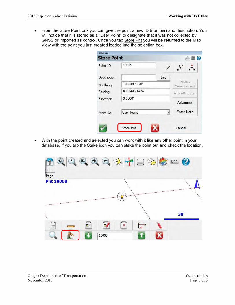
From the Store Point box you can give the point a new ID (number) and description. You will notice that it is stored as a “User Point” to designate that it was not collected by GNSS or imported as control. Once you tap Store Pnt you will be returned to the Map View with the point you just created loaded into the selection box.
With the point created and selected you can work with it like any other point in your database. If you tap the Stake icon you can stake the point out and check the location.
Working with DXF files 2015 Inspector Gadget Training
Geometronics Oregon Department of Transportation Page 4 of 5 November 2015
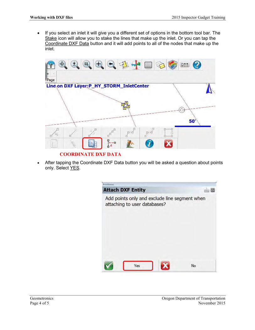
If you select an inlet it will give you a different set of options in the bottom tool bar. The Stake icon will allow you to stake the lines that make up the inlet. Or you can tap the Coordinate DXF Data button and it will add points to all of the nodes that make up the inlet.
After tapping the Coordinate DXF Data button you will be asked a question about points only. Select YES.
COORDINATE DXF DATA

2015 Inspector Gadget Training Working with DXF files
Oregon Department of Transportation Geometronics November 2015 Page 5 of 5
You will now have points at all of the nodes that defined the inlet.
You can use these same procedures on almost any line or feature within a DXF file. If
the lines and features are 3D you will be able to stake the design elevations as well as the design location. If they are only 2D you will only be given a location and the elevation will default to 0.00’.
OREGON DEPARTMENT
OF TRANSPORTATION
Engineering Automation Section
4040 Fairview Industrial Dr. SE MS 4 Salem, OR 97302-1142
(503) 986-3103
Ron Singh, PLS Engineering Automation
Section Manager Chief of Surveys (503) 986-3033
Chris Pucci, PLS Construction Automation
Surveyor (503) 986-3542
Exporting FieldGenius LandXML files for use in
InRoads
Title Exporting LandXML files for use in Inroads Version FG 8.2 Date September, 7 2016 Author Chris Pucci
Overview This document will guide you through the process of exporting LandXML files from FieldGenius and importing them into InRoads.

2016 GNSS Inspector Tablet Training Exporting LandXML files
Oregon Department of Transportation Engineering Automation September 2016 Page 1 of 16
Introduction
• There are many options for exporting data from FieldGenius for use in MicroStation and Inroads. You may find that exporting files in LandXML format is useful for transferring points, lines, and closed figures all with one file. This guide will give you the steps required to export a LandXML file from FieldGenius and import it into InRoads and begin using the data.
• We will start with the assumption you have collected points and lines on your project.

Exporting LandXML files 2016 GNSS Inspector Tablet Training
Engineering Automation Oregon Department of Transportation Page 2 of 16 September 2016
Exporting a LandXML file from FieldGenius
• From the FieldGenius Main Menu select Import/Export

2016 GNSS Inspector Tablet Training Exporting LandXML files
Oregon Department of Transportation Engineering Automation September 2016 Page 3 of 16
• From the Import/Export menu select LandXML Export (Points and Chains)

Exporting LandXML files 2016 GNSS Inspector Tablet Training
Engineering Automation Oregon Department of Transportation Page 4 of 16 September 2016
• You will be prompted to select a location for the file and type a name. (I am saving the file directly to the USB drive to skip a step of transferring the file from the hard drive to the USB drive.)
2016 GNSS Inspector Tablet Training Exporting LandXML files
Oregon Department of Transportation Engineering Automation September 2016 Page 5 of 16
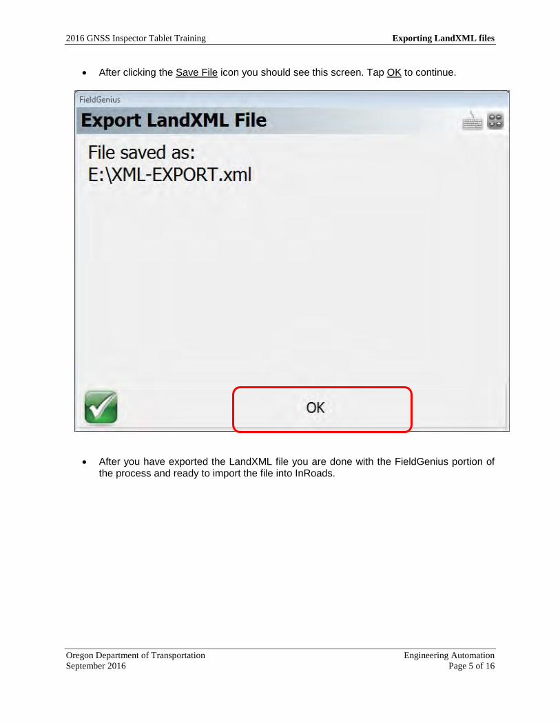
• After clicking the Save File icon you should see this screen. Tap OK to continue.
• After you have exported the LandXML file you are done with the FieldGenius portion of the process and ready to import the file into InRoads.

Exporting LandXML files 2016 GNSS Inspector Tablet Training
Engineering Automation Oregon Department of Transportation Page 6 of 16 September 2016
Importing a LandXML into InRoads
• With a MicroStation file opened and InRoads open, click on the File tab in InRoads and open the LandXML Translator.

2016 GNSS Inspector Tablet Training Exporting LandXML files
Oregon Department of Transportation Engineering Automation September 2016 Page 7 of 16
• From the LandXML translator, click all of the import options ON by checking the boxes, set your feature style to ODOT and click Browse to locate the LandXML file you exported from FieldGenius.

Exporting LandXML files 2016 GNSS Inspector Tablet Training
Engineering Automation Oregon Department of Transportation Page 8 of 16 September 2016
• Browse to your LandXML file and click Open

2016 GNSS Inspector Tablet Training Exporting LandXML files
Oregon Department of Transportation Engineering Automation September 2016 Page 9 of 16
• You will then need to click Apply and then click Close on the LandXML translator. If all has gone as planned you will now have data loaded into InRoads!

Exporting LandXML files 2016 GNSS Inspector Tablet Training
Engineering Automation Oregon Department of Transportation Page 10 of 16 September 2016
• Your points will be located under the Geometry tab in the Cogo Buffer
2016 GNSS Inspector Tablet Training Exporting LandXML files
Oregon Department of Transportation Engineering Automation September 2016 Page 11 of 16
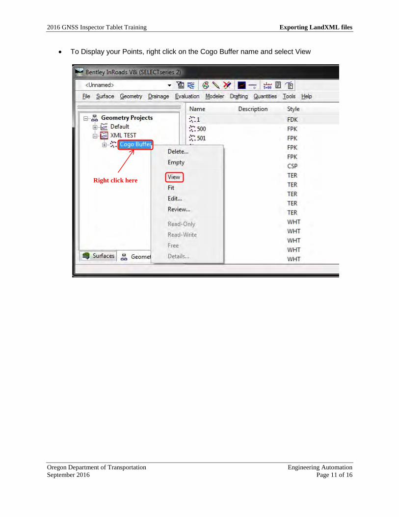
• To Display your Points, right click on the Cogo Buffer name and select View
Right click here

Exporting LandXML files 2016 GNSS Inspector Tablet Training
Engineering Automation Oregon Department of Transportation Page 12 of 16 September 2016
• From the View Horizontal Annotation menu, select all of your points by typing a “*” symbol into the Cogo Points - Include box or by typing the point range you want to display. Once you have the points listed in the selection set, click Apply and then Close. You will now have points displayed in your drawing!
2016 GNSS Inspector Tablet Training Exporting LandXML files
Oregon Department of Transportation Engineering Automation September 2016 Page 13 of 16
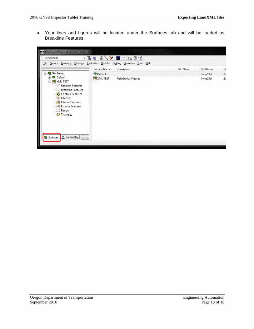
• Your lines and figures will be located under the Surfaces tab and will be loaded as Breakline Features
Exporting LandXML files 2016 GNSS Inspector Tablet Training
Engineering Automation Oregon Department of Transportation Page 14 of 16 September 2016
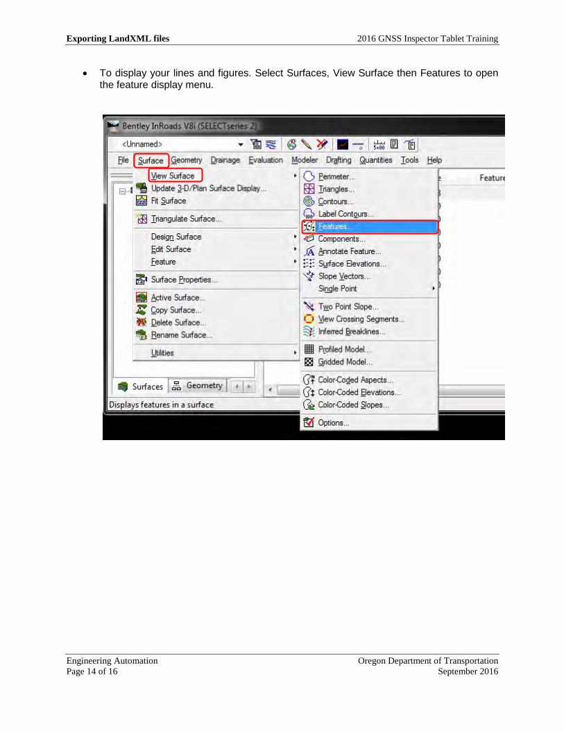
• To display your lines and figures. Select Surfaces, View Surface then Features to open the feature display menu.

2016 GNSS Inspector Tablet Training Exporting LandXML files
Oregon Department of Transportation Engineering Automation September 2016 Page 15 of 16
• The View Features menu will open. It will have all features defaulting to display. You can turn features on and off as needed by highlighting or un-highlighting. Once you have your selection set as you want it, click Apply and then Close. All of your lines and features will be displayed!

Exporting LandXML files 2016 GNSS Inspector Tablet Training
Engineering Automation Oregon Department of Transportation Page 16 of 16 September 2016
• With all of the points and lines displayed, you can work with them any way you want.

Inspector Tablet
A
ntenna Settings – Select HE
MI P303 O
RG
N
configuration for both internal and external antenna A
PR to A
PC A
ntenna Offsets
Internal: +/- 84.3mm
External W
hite (Leica): 58.3mm
External G
ray (AY
IA): 60.0m
m
A
ntenna Height
Internal HEM
I P303 – Distance from
tablet to point External on fixed rod – 6.562 feet // 2m
eters
NT
RIP C
ASTE
R Settings
OR
GN
MA
X G
G: 167.131.109.57, Port 9882
OR
GN
Single: 167.131.109.57, Port 9879
User N
ame: X
XTA
BXX
, Password: G
RA
DE
Data Form
at: RTCM
3
RT
K R
adio Settings G
S14 2015 Models – Satel O
EM22 – C
hannel 2 G
S14 2013 Models – Satel O
EM20 – C
hannel 2
To Access M
ain Menu
Instrument / C
onnection settings To Store a point tap this icon Opens Point D
atabase
T
echnical Questions/Support/H
elp C
hris P
ucci, P
LS
K
evin L
aV
erdure, P
LS
Const. A
uto
matio
n S
urveyo
r
Lea
d S
urveyo
r
Desk (5
03) 9
86-3
542
(50
3) 9
86
-30
17
Cell (5
03) 3
02-5
474