ODOT Traffic Manual - oregon.gov · 4.2 Forest Highway Tri-Agency Committee ... 4.7 Oregon Travel...
166
Traffic Manual 2018 Edition Published January 2018 Oregon Department of Transportation Highway Division—Technical Services Traffic-Roadway Section http://www.oregon.gov/ODOT/Engineering/pages/index.aspx
Transcript of ODOT Traffic Manual - oregon.gov · 4.2 Forest Highway Tri-Agency Committee ... 4.7 Oregon Travel...
Traffic Manual
2018 Edition Published
January 2018
Oregon Department of Transportation Highway Division—Technical Services
Traffic-Roadway Section http://www.oregon.gov/ODOT/Engineering/pages/index.aspx

Oregon Department of Transportation Traffic Manual
Traffic Manual—2018 Edition ODOT Published January 2018 Page ii
Summary of Major Changes for the ODOT Traffic Manual—2018 Edition
Chapter 3–Publications
Updated publication title names.
Chapter 4—Traffic Engineering and Operations Teams
Updated names and descriptions to match committee charters and bylaws.
Chapter 5—Delegated Authority
Added reference to Rumble Strips Section 6.28 for the updated rumble strip policy in Tech Bulletin TR17-03(B).
Updated Audible Pedestrian Signal terminology to match the Signal Policy and Guidelines.
Added reference to the Signal Design Manual for provisions and requirements on pedestrian signal layout related to approvals on moving or relocating pedestrian push buttons.
Chapter 6—Traffic Engineering Practices
Updated Section 6.1 Access Management to match Access Management terminology and OAR references.
Revised Section 6.4 Capacity Analysis to be consistent with Analysis Procedures Manual methods.
Revised Section 6.12.1 Interchange Modification Requests to be consistent with the updated FHWA Interstate Access Policy dated May 22, 2017.
Revised Section 6.14.1 Intersection Traffic Control Study to remove conflicts with Chapter 1 and Appendix C in the Traffic Signal Policy and Guidelines and Section 6.4.1 in the Analysis Procedures Manual.
Updated the name of the ODOT Rail Division to the ODOT Rail & Public Transit Division in various sections.
Corrected typo in SPIS formula in Section 6.10.5.2.
Revised Section 6.16.2 Lane Reduction Transitions to resolve conflicts with the MUTCD, Traffic Line Manual, and Sign Design Manual.
Revised Section 6.23.1 On-Street Parking to be consistent with Section 6.2.2.5 in the Highway Design Manual.
Removed redundant paragraph from Section 6.23.2 Parking Prohibitions and Restrictions.
Oregon Department of Transportation Traffic Manual
Traffic Manual—2018 Edition ODOT Published January 2018 Page iii
Revised 6.24 Pavement Markings to match current Pavement Marking publications and the MUTCD.
Revised Section 6.25.2 Added Stop Lanes to match Rail & Public Transit’s process for modifying a grade crossing.
Updated Section 6.28 Rumble Strips to reference Tech Bulletin TR17-03(B) Policy for Installing Longitudinal Rumble Strips on STIP Projects on State Highways and removed conflicts with the Tech Bulletin.
Updated Section 6.29 Safe Speed on Curves to reference Tech Bulletin TR15-01(B) Statewide Policy for Installing Chevrons, Arrows, and Advisory Speed Plaques and removed conflicts with the Tech Bulletin.
Revised Section 6.31 Sight Distance to reference the MUTCD and Traffic Line Manual for the process to determine Passing Sight Distance instead of the AASHTO Green Book.
Updated contact information for sign requests in Section 6.32 Signs.
Revised Section 6.32.5 Wrong Way Treatments to reference other sections of the MUTCD, Sign Design Manual, and Traffic Line Manual.
Revised Section 6.34.3 Construction Speed Zones to remove conflicts with the updated request process and guidance in the Traffic Control Plans Design Manual.
Updated references to websites in various sections.
Updated ORS references in Section 6.34.6 Photo Radar Speed Enforcement.
Updated Section 6.36 Traffic Signals to resolve conflicts with the Signal Policy and Guidelines.
Added reference in Section 6.42 to the Vertical Clearance Tech Bulletin RD17-02(B) and Highway Directive TRA 07-15.
Revised Section 6.43.2 Portable Traffic Signals to resolve conflicts with the Oregon Temporary Traffic Control Handbook, Traffic Control Plans Design Manual, Traffic Signal Design Manual, and Signal Policy and Guidelines.
Chapter 7—Appendices
Updated Section 7.2 Forms to match forms that are currently in use.
Revised Section 7.4 Crash Analysis. Content in this section was intended to be replaced with the Safety Investigations Manual was published. The Safety Investigations Manual is now published.
Updated definitions of Qualified Personnel to resolve conflict with current TSSU training program and Traversable Median to reference the change in meaning “crosshatching” makes under ORS 811.430.
Oregon Department of Transportation Traffic Manual
Traffic Manual—2018 Edition ODOT Published January 2018 Page iv
TABLE OF CONTENTS
1 INTRODUCTION ........................................................................................................... 1-1
1.1 Traffic Manual ........................................................................................................... 1-1 1.1.1 Goals and Objectives ...................................................................................... 1-1 1.1.2 Purpose .......................................................................................................... 1-1
1.2 Highway Design Manual ............................................................................................ 1-1
2 GENERAL ................................................................................................................... 2-1
2.1 Traffic-Roadway Section ........................................................................................... 2-1 2.1.1 Overview......................................................................................................... 2-1 2.1.2 Organizational Structure ................................................................................. 2-1
2.2 Region Traffic Unit .................................................................................................... 2-3 2.2.1 Region Traffic Design and Operations ............................................................ 2-3 2.2.2 Region Traffic Investigations ........................................................................... 2-4 2.2.3 Region Transportation Safety Coordinator ...................................................... 2-4 2.2.4 Region Intelligent Transportation System (ITS) Activities ................................ 2-4 2.2.5 Region Access Management .......................................................................... 2-4
2.3 Other Traffic Related Units within ODOT ................................................................... 2-4 2.3.1 Intelligent Transportation Systems Unit ........................................................... 2-4 2.3.2 Traffic Systems Services Unit ......................................................................... 2-5 2.3.3 Crash Analysis and Reporting Unit ................................................................. 2-6 2.3.4 Transportation Systems Monitoring Unit ......................................................... 2-6 2.3.5 Transportation Planning Analysis Unit ............................................................ 2-6
3 PUBLICATIONS ............................................................................................................ 3-1
4 TRAFFIC ENGINEERING AND OPERATIONS TEAMS ......................................................... 4-1
4.1 AASHTO Committees ............................................................................................... 4-1 4.1.1 Standing Highway Committee, Subcommittee on Traffic Engineering ............. 4-1 4.1.2 Subcommittee on System Operations and Management ................................ 4-1
4.2 Forest Highway Tri-Agency Committee ..................................................................... 4-1 4.3 Highway Safety Engineering Committee ................................................................... 4-1 4.4 MaxTime Software Users Group ............................................................................... 4-2 4.5 Oregon Historical Marker Committee ........................................................................ 4-2 4.6 Oregon Traffic Control Devices Committee (OTCDC) ............................................... 4-2 4.7 Oregon Travel Experience......................................................................................... 4-2 4.8 Statewide Pavement Marking Committee .................................................................. 4-3 4.9 Pavement Marking Design Working Group ................................................................ 4-3 4.10 Safety Investigations Group ...................................................................................... 4-3 4.11 Signal Timers Group ................................................................................................. 4-4 4.12 Speed Zone Review Panel ........................................................................................ 4-4 4.13 Statewide Grant Review Committee .......................................................................... 4-4 4.14 Traffic Control Plans Discipline Group ....................................................................... 4-4 4.15 Traffic Control Plans Technology Committee ............................................................ 4-5 4.16 Traffic Control Oversight Committee ......................................................................... 4-5 4.17 Traffic –Roadway Section/Transportation Safety Division ......................................... 4-5
Oregon Department of Transportation Traffic Manual
Traffic Manual—2018 Edition ODOT Published January 2018 Page v
4.18 Traffic Operations Leadership Team (TOLT) .............................................................4-5 4.19 Traffic Sign Design Working Group ...........................................................................4-6 4.20 Traffic Signal Design Working Group .........................................................................4-6 4.21 TransPort Committee ................................................................................................4-6 4.22 Traffic Structures Design Working Group ..................................................................4-7
5 DELEGATED AUTHORITY ............................................................................................. 5-1
5.1 Delegated Authorities of the State Traffic-Roadway Engineer ...................................5-1 5.1.1 Traffic Control Devices ................................................................................... 5-1 5.1.2 Traffic Signals and Bicycle/Pedestrian Activated Warning Systems ............... 5-4 5.1.3 Intelligent Transportation System Devices ..................................................... 5-6
6 TRAFFIC ENGINEERING PRACTICES ............................................................................. 6-1
6.1 Access Management .................................................................................................6-1 6.1.1 Overview ........................................................................................................ 6-1 6.1.2 Grants of Access ............................................................................................ 6-2
6.2 Active Warning Signs at Bridges and Tunnels ...........................................................6-3 6.2.1 Background .................................................................................................... 6-3 6.2.2 Criteria ........................................................................................................... 6-3 6.2.3 Considerations ............................................................................................... 6-4 6.2.4 Engineering Study .......................................................................................... 6-4
6.3 Bicycle Facilities ........................................................................................................6-5 6.4 Capacity Analysis ......................................................................................................6-5 6.5 Crash Analysis ..........................................................................................................6-5
6.5.1 Overview ........................................................................................................ 6-5 6.5.2 Crash Analysis Data Sources ......................................................................... 6-6
6.6 Crosswalks ................................................................................................................6-8 6.6.1 Marked Crosswalks at Uncontrolled Locations on State Highways ................. 6-8 6.6.2 Criteria for Establishing Marked Crosswalks on State Highways .................. 6-10 6.6.3 Crosswalk Approval ..................................................................................... 6-19 6.6.4 Crosswalk Closures and Removals .............................................................. 6-20 6.6.5 Crosswalk Safety ......................................................................................... 6-20 6.6.6 Crossing Strategies ...................................................................................... 6-21 6.6.7 Pedestrian Activated Warning Lights ............................................................ 6-23 6.6.8 Textured/Colored Crosswalks ...................................................................... 6-28
6.7 Flashing Beacons .................................................................................................... 6-30 6.7.1 Intersection Control Beacon ......................................................................... 6-30 6.7.2 Warning Beacon .......................................................................................... 6-30 6.7.3 Speed Limit Sign Beacon ............................................................................. 6-31 6.7.4 Stop Beacon ................................................................................................ 6-31
6.8 Freeway Median Crossovers ................................................................................... 6-31 6.8.1 Overview ...................................................................................................... 6-31 6.8.2 Considerations ............................................................................................. 6-31 6.8.3 Criteria ......................................................................................................... 6-32
6.9 Highway Advisory Radio .......................................................................................... 6-32 6.9.1 Guidelines for the Operation of Highway Advisory Radio and Traveler's Advisory Radio on State Highways .......................................................................................... 6-33
6.10 Highway Safety Engineering .................................................................................... 6-33 6.10.1 All Roads Transportation Safety (ARTS) Program ....................................... 6-33 6.10.2 State Strategic Highway Safety Plan ............................................................ 6-34
Oregon Department of Transportation Traffic Manual
Traffic Manual—2018 Edition ODOT Published January 2018 Page vi
6.10.3 Program Management .................................................................................. 6-34 6.10.4 Highway Safety Engineering Committee ....................................................... 6-34 6.10.5 Safety Priority Index System (SPIS) .............................................................. 6-34
6.11 Historical Markers ................................................................................................... 6-36 6.12 Interchanges ........................................................................................................... 6-37
6.12.1 Interchange Modification Request ................................................................. 6-37 6.13 Illumination .............................................................................................................. 6-37
6.13.1 Overview....................................................................................................... 6-37 6.13.2 Temporary Illumination ................................................................................. 6-37 6.13.3 Permanent Illumination ................................................................................. 6-38
6.14 Intersections ............................................................................................................ 6-38 6.14.1 Intersection Traffic Control Study .................................................................. 6-39
6.15 Land Use and Transportation .................................................................................. 6-42 6.16 Lanes ...................................................................................................................... 6-42
6.16.1 Climbing and Passing Lanes......................................................................... 6-42 6.16.2 Lane Reduction Transition ............................................................................ 6-43 6.16.3 Right-Turn Acceleration Lanes ...................................................................... 6-43 6.16.4 Turn Lanes ................................................................................................... 6-43
6.17 Legislature .............................................................................................................. 6-43 6.18 Litigation .................................................................................................................. 6-43 6.19 Manual on Uniform Traffic Control Devices ............................................................. 6-44
6.19.1 Overview....................................................................................................... 6-44 6.19.2 Oregon Supplement to the MUTCD .............................................................. 6-44 6.19.3 Exceptions to the MUTCD ............................................................................ 6-45 6.19.4 Deviations to the MUTCD ............................................................................. 6-45 6.19.5 Requests to Experiment ................................................................................ 6-45 6.19.6 Revisions to the MUTCD (Changes) ............................................................. 6-45
6.20 Naming Highway Facilities ...................................................................................... 6-45 6.21 New Products .......................................................................................................... 6-46 6.22 One-way Operation for Trucks and Buses ............................................................... 6-46 6.23 Parking .................................................................................................................... 6-47
6.23.1 On-Street Parking ......................................................................................... 6-47 6.23.2 Prohibitions and Restrictions......................................................................... 6-47
6.24 Pavement Markings................................................................................................. 6-48 6.24.1 Overview....................................................................................................... 6-48 6.24.2 Advance Stop Bars ....................................................................................... 6-49 6.24.3 No Passing Zones ........................................................................................ 6-50 6.24.4 Two-Way Left Turn Lane .............................................................................. 6-51 6.24.5 Yield Control Markings .................................................................................. 6-51 6.24.6 Colored Pavements ...................................................................................... 6-51 6.24.7 Shared Lane Markings .................................................................................. 6-51
6.25 Railroad Crossings .................................................................................................. 6-53 6.25.1 Overview....................................................................................................... 6-53 6.25.2 Added Stop Lanes ........................................................................................ 6-53
6.26 Road Closures ........................................................................................................ 6-54 6.27 Roundabouts ........................................................................................................... 6-54
6.27.1 Overview....................................................................................................... 6-54 6.27.2 Roundabout Selection Criteria and Approval Process ................................... 6-55
6.28 Rumble Strips.......................................................................................................... 6-59 6.28.1 Shoulder Rumble Strips (SRS) ..................................................................... 6-59 6.28.2 Centerline Rumble Strips (CLRS) ................................................................. 6-60
Oregon Department of Transportation Traffic Manual
Traffic Manual—2018 Edition ODOT Published January 2018 Page vii
6.28.3 Transverse Rumble Strips ............................................................................ 6-60 6.29 Safe Speed on Curves ............................................................................................ 6-62 6.30 Safety Corridors ...................................................................................................... 6-62 6.31 Sight Distance ......................................................................................................... 6-62 6.32 Signs ....................................................................................................................... 6-63
6.32.1 Sign Policy and Guidelines for the State Highway System ........................... 6-63 6.32.2 Right-Turn Permitted Without Stopping (RTPWS) ........................................ 6-65 6.32.3 STOP Sign Applications ............................................................................... 6-65 6.32.4 Variable Message Signs .............................................................................. 6-66 6.32.5 Wrong Way Treatments ............................................................................... 6-67 6.32.6 YIELD Sign Applications .............................................................................. 6-68
6.33 Special Events ......................................................................................................... 6-69 6.34 Speed Zones ........................................................................................................... 6-69
6.34.1 Overview ...................................................................................................... 6-69 6.34.2 Variable Speed Zones .................................................................................. 6-70 6.34.3 Construction Speed Zones ........................................................................... 6-70 6.34.4 School Speed Zone ..................................................................................... 6-70 6.34.5 Vehicle Speed Feedback Sign ..................................................................... 6-71 6.34.6 Photo Radar Speed Enforcement................................................................. 6-72
6.35 Traffic Calming ........................................................................................................ 6-73 6.36 Traffic Signals .......................................................................................................... 6-74
6.36.1 Traffic Signal Approval Process ................................................................... 6-74 6.36.2 Traffic Signal Operations .............................................................................. 6-75 6.36.3 Traffic Signal Enforcement ........................................................................... 6-79
6.37 Traffic Impact Studies .............................................................................................. 6-81 6.38 Truck Routes ........................................................................................................... 6-81
6.38.1 Background .................................................................................................. 6-81 6.38.2 Procedure .................................................................................................... 6-82
6.39 Turn Lanes .............................................................................................................. 6-82 6.39.1 Left-Turn Lanes ............................................................................................ 6-82 6.39.2 Multiple Turn Lanes ..................................................................................... 6-82 6.39.3 Right-Turn Lanes ......................................................................................... 6-84 6.39.4 179B179BShared (or combined) Bike and Right-Turn Lane ......................................... 6-89 6.39.5 180B180BTransit Exceptions to Turn Lanes ................................................................. 6-90 6.39.6 181B181BTwo-Way Left Turn Lanes and Painted Medians .......................................... 6-91
6.40 76B76BTurn Prohibitions ..................................................................................................... 6-92 6.41 77B77BU-turns at Signalized Intersections .......................................................................... 6-92 6.42 78B78BVisibility ................................................................................................................... 6-93 6.43 79B79BWork Zones ............................................................................................................. 6-93
6.43.1 182B182BAnalysis ....................................................................................................... 6-93 6.43.2 183B183BPortable Traffic Signals ................................................................................ 6-95 6.43.3 184B184BOregon Temporary Traffic Control Handbook .............................................. 6-96
7 6B6BAPPENDICES .............................................................................................................. 7-1
7.1 80B80BDefinitions .................................................................................................................7-1 7.2 81B81BForms ........................................................................................................................7-7
7.2.1 Signs .............................................................................................................. 7-7 7.2.2 186B186BPreliminary Traffic Signal Warrant Analysis .................................................... 7-7 7.2.3 187B187BTraffic Signal Warrant Analysis ...................................................................... 7-7 7.2.4 188B188BTraffic Signal Approval Request Form ............................................................ 7-7
Oregon Department of Transportation Traffic Manual
Traffic Manual—2018 Edition ODOT Published January 2018 Page viii
7.2.5 189B189BWorksheet for Determining the Need for a Reduced Speed Zone for Work Zones 7-7 7.2.6 190B190BParking Prohibition Request Form .................................................................. 7-7
7.3 82B82BFiles .......................................................................................................................... 7-8 7.4 83B83BCrash Analysis ........................................................................................................ 7-11 7.5 84B84BTraffic Engineering Programs .................................................................................. 7-11
7.5.1 199B199BBlue Star Memorial Program ......................................................................... 7-11 7.5.2 200B200BImpaired Driving Victim Memorial Signing ..................................................... 7-12
7.6 85B85BLegal Authority ........................................................................................................ 7-15 7.6.1 201B201BCrosswalks ................................................................................................... 7-15 7.6.2 202B202BDelegation of Authority .................................................................................. 7-15 7.6.3 203B203BEmergency Vehicle Preemption .................................................................... 7-15 7.6.4 204B204BFreeway Median Crossovers ........................................................................ 7-15 7.6.5 205B205BIncident Management ................................................................................... 7-15 7.6.6 206B206BJurisdiction .................................................................................................... 7-15 7.6.7 207B207BMultiple Turns at Highway Intersections ........................................................ 7-16 7.6.8 208B208BOne-way Operation, Transit Exceptions ........................................................ 7-16 7.6.9 209B209BParking Prohibitions ...................................................................................... 7-16 7.6.10 210B210BRestrictions by Vehicle Type or Weight ......................................................... 7-16 7.6.11 211B211BSchool Zones ................................................................................................ 7-16 7.6.12 212B212BSpeed Zones ................................................................................................ 7-16 7.6.13 213B213BTraffic Control Device, Appropriate Driver Responses .................................. 7-16 7.6.14 214B214BTraffic Signal Approval Process .................................................................... 7-17 7.6.15 215B215BTransit and HOV Lanes ................................................................................ 7-17 7.6.16 216B216BTurn Prohibitions ........................................................................................... 7-17 7.6.17 217B217BUniform Standards and Placement ............................................................... 7-17 7.6.18 218B218BU-turn Designations ...................................................................................... 7-17
8 7B7BREFERENCES ............................................................................................................. 8-1
9 8B8BGLOSSARY ................................................................................................................. 9-1
Traffic Manual—2018 Edition ODOT Published January 2018 Page 1-1
1 INTRODUCTION
1.1 Traffic Manual
The Traffic Manual focuses on ODOT traffic engineering policies and practices. The manual also clarifies roles and responsibilities, as well as providing information that may be required when considering traffic control changes.
1.1.1 Goals and Objectives
The goals and objectives of the policies and procedures contained in the Traffic Manual are to enhance the safety and efficiency of Oregon’s transportation system by providing guidance for traffic operations, maintenance and project delivery.
1.1.2 Purpose
The material contained in this document is for reference and information purposes only to aid new employees and those unfamiliar with ODOT traffic engineering practices in accessing applicable standards, statutes, rules and policies. Its primary purpose is to provide our customers and new employees with information regarding practices, procedures, and organization. The manual will also clarify roles and responsibilities, as well as provide information that may be required when considering traffic control changes. This manual includes information on where to find policies, procedures, warrants, and design considerations for traffic related items. The manual should not be regarded as policy, rather it should be used for information and training.
Every effort was taken to carefully edit and assemble this manual; however omissions and errors can occur. If you have any questions or comments on the contents, format or wording of this document please submit them in writing to the State Traffic-Roadway Engineer.
State Traffic-Roadway Engineer Oregon Department of Transportation Traffic-Roadway Section 4040 Fairview Industrial Drive SE Salem, OR 97302-1142
1.2 Highway Design Manual
Highway design practices and policies are not found in the Traffic Manual. For issues related to geometric design and roadway engineering, users should consult the Highway Design Manual maintained by the Roadway Engineering Services Unit of the Traffic-Roadway Section.

Traffic Manual—2018 Edition ODOT Published January 2018 Page 2-1
2 GENERAL
2.1 Traffic-Roadway Section
2.1.1 Overview
The Traffic-Roadway Section is within Technical Services, which is part of the Highway Division. Technical Services consists of five sections: Bridge Engineering, Geo-Environmental, Construction, Right of Way, and Traffic—Roadway. There are approximately 340 employees in Technical Services, with an operating budget of approximately $77 million per biennium. Technical Services maintains liaison with the Regions during the Four-Year Statewide Transportation Improvement Program (STIP) plan development and field location design; provides support to the Regions in delivering Oregon Transportation Investment Act (OTIA) projects; identifies and purchases needed right-of-way; develops standards and specifications for all transportation facilities; and provides related design, materials, operations, and construction support services.
The Traffic-Roadway Section has approximately 80 employees and was formed in September 2006 by merging the former Traffic Engineering and Operations Section with the Roadway Engineering Section. Traffic-Roadway Section traffic engineering programs affect all ODOT divisions, the State Police, the Public Utilities Commission, cities and counties, Oregon Travel Experience, motorist services providers, the Speed Zone Review Panel, the Oregon Transportation Safety Committee, and all road users on all public roads in Oregon. The traffic engineering programs at ODOT provide statewide policies and guidelines for all traffic control devices; develops and maintains standards for traffic signals, illumination, signing, striping, and work zone traffic control; provides technical analysis for traffic operation improvements on all state highways; administers the federal Highway Safety Improvement Program (HSIP); manages programs; manages speed zoning for all public roads; monitors traffic speeds; and optimizes operation of statewide traffic signal systems.
2.1.2 Organizational Structure
The Traffic-Roadway Section was reorganized in May 2011 to include six central units: Access Management Unit, Roadway Engineering Services Unit, Office of Project Letting Unit, Geometronics Unit, Traffic Standards and Asset Management Unit, and Traffic Engineering Services Unit. The latter two units which focus exclusively on traffic engineering issues are described in more detail below.
2.1.2.1 Traffic Standards and Asset Management Unit
The Traffic Standards and Asset Management Unit has expertise in a wide variety of installations related to roadway signing, striping, traffic structures, traffic control plans, and traffic signals. The unit’s primary purpose is to develop and maintain standards for design and construction, review contract plans, provide training in design and construction inspection, and asset management of signs, signals, and traffic structures. The unit also provides standard drawings, special provisions, and specialized work as needed. This unit consists of four teams providing expertise in the following areas:
Traffic Manual—2018 Edition ODOT Published January 2018 Page 2-2
Signing and Striping
Provides engineering expertise and maintains standards for all highway signs and pavement markings (see Sign Policy and Guidelines for the State Highway System, and Striping Design Guidelines). The team also develops specifications, maintains standard drawings, reviews new products, and develops manuals to provide training for designers. The team may provide some designs for ODOT regions.
Traffic Signals
Provides engineering expertise for temporary traffic signals, permanent traffic signals, flashing beacons, ramp meters and some portions of weigh stations. The team also develops specifications, maintains standard drawings, and maintains qualified products lists. The team also reviews local agency and developer agreements and plans for traffic control devices, reviews new products, maintains asset management databases, and provides annual training and certification for inspectors of traffic signal construction. The team also produces some designs for Regions on an as requested basis.
Traffic Structures
Provides engineering expertise and designs for sign bridges, cantilever sign supports, traffic signal poles, illumination poles, VMS supports and other miscellaneous traffic structures.
Traffic Control Plans
Develops the standards for traffic control plans for construction projects. When construction projects suspend the normal function of the roadway, a traffic control plan is developed to assure the safety of all road users, and the protection of workers. At the same time, the traffic control plan provides for continuity of the movement of motor vehicles, bicycle and pedestrian traffic while allowing for the efficient completion of the construction project.
Illumination
Provide engineering expertise, designs and standards for roadway illumination.
2.1.2.2 Traffic Engineering Services Unit
The Traffic Engineering Services Unit consists of two work teams. The teams provide engineering services in the following areas:
Safety and Investigations
Provides highway safety analyses; maintain the Safety Priority Index System (SPIS); administers the Highway Safety Improvement Program (HSIP) and Project Safety Management System as well as safety tools used within ODOT; and provides coordination and liaison for safety efforts with other parts of ODOT and outside agencies, including the Highway Safety Engineering Committee and the Oregon Transportation Safety Committee.
The group also provides traffic engineering expertise for research studies, legislative issues, crash analyses, safety reviews, access management issues, review and approval of traffic engineering delegated authorities, speed monitoring, speed zoning, new products, highway litigation and tort liability as well as supporting the Speed Zone Review Panel.
Traffic Manual—2018 Edition ODOT Published January 2018 Page 2-3
The Safety and Investigations group provides expertise for the development and update of traffic engineering policies, procedures and ODOT manuals. The group also gathers and provides input and recommendations for any proposed changes to the Manual on Uniform Traffic Control Devices, maintains and updates the Oregon Supplement to the MUTCD and works with the Oregon Traffic Control Devices Committee (OTCDC) to establish statewide traffic control standards.
Signal Operations
The Signal Operations group prepares traffic signal and signal system timing, and provides engineering expertise in traffic signal operation, installation of traffic signals, traffic signal approvals, vehicle detection systems, traffic signal software and communication development, ramp meter system operations and railroad preemption systems. The Signal Operations team also provides engineering support for transportation operations research and analysis, HOV lane applications, and signal mounted preemption system design (for emergency and transit vehicles). The group also provides expertise for the development of traffic engineering policies, procedures and proposed legislation.
2.2 Region Traffic Unit
A Region Traffic Unit is located in each of the five ODOT Regions throughout the state. The Region Traffic Unit is part of each Region’s Technical Center and reports directly to the Technical Center manager.
Region Traffic Unit staff provide expertise to the region and district staff on current traffic policies and procedures. Staff are responsible for overseeing most traffic engineering design including most signal and sign design for Region projects. Staff actively participate as members of project development teams to help insure that traffic related issues are considered early in the process and to provide traffic information to the team. They also act as the traffic liaison to local agencies on behalf of ODOT.
Members of the unit conduct field investigations at the request of the public, local government, or ODOT personnel. When requested, they conduct engineering investigations, determine appropriate solutions, make written recommendations, and when necessary, request approval of the State Traffic-Roadway Engineer for installation of traffic control devices or modifications to traffic control.
Engineering investigations for changes to traffic control devices often result from safety concerns and can include requests for signs, signals, striping, parking restrictions and speed reductions. They also conduct field safety investigations of the sites and make recommendations for corrective action. Staff also conduct speed zone investigations and/or oversee consultants performing the work and make recommendations for changes to the State Traffic-Roadway Engineer based on the results.
2.2.1 Region Traffic Design and Operations
Region Traffic Unit staff oversee design for all Region projects containing traffic engineering elements including signing, striping, and signals. The units provide expertise in signal timing, operations, and vehicle detection systems. They may also provide expertise for the operation of ramp metering systems. Signal system coordination is done in Regions 1 and 2 by the Region Traffic Unit staff. Regions 3, 4, and 5 signal coordination is handled by
Traffic Manual—2018 Edition ODOT Published January 2018 Page 2-4
Traffic-Roadway Section staff. Some units oversee signing, striping and electrical crews for their region.
2.2.2 Region Traffic Investigations
Staff reviews traffic studies for developments and land use actions for their impacts to the state highway system and make recommendations regarding access, traffic mitigation requirements, safety and operation of the State Highway system. They also review corridor plans and Transportation System Plans (TSPs) for traffic-related issues.
2.2.3 Region Transportation Safety Coordinator
Each Region Traffic Unit has a traffic safety advocate (Region Transportation Safety Coordinator) who is a technical resource for local safety education and law enforcement efforts, and provides access to safety grant funds, materials and training. They handle programs regarding education on child occupant protection, DUII, pedestrian, teen driving, bicycle, and work zone enforcement. They also work with local safety committees on traffic issues.
2.2.4 Region Intelligent Transportation System (ITS) Activities
Region Traffic Units often oversee Intelligent Transportation System (ITS) related activities in their areas. The Traffic Management and Operations Centers monitor and control traffic operations through the latest Intelligent Transportation Systems (ITS) technologies to provide real-time transportation system control, communications, monitoring and information.
The ITS unit is part of the Maintenance and Operations Branch and not part of Traffic-Roadway Section (see ITS unit below).
2.2.5 Region Access Management
Region Traffic Unit staff are often involved in the access management programs for each Region (some Regions incorporate Access Management into the Region Traffic Unit while others incorporate it into Planning). Each Region has a Region Access Management Engineer (RAME) who provides key technical support for access management practices in the region. The RAMEs also provide a valuable communication link between central staff and region staff and act as an ODOT advisory group on access management issues, policies and practices.
2.3 Other Traffic Related Units within ODOT
2.3.1 Intelligent Transportation Systems Unit
Within the Maintenance and Operations Branch, the Intelligent Transportation Systems Unit provides identification, planning, design, specification and deployment of ITS systems including incident management systems, some communication systems and travelers’ information systems. Some of the device types include cameras, weather stations, variable message signs, ramp meters, highway advisory radio (including HAR signs), automatic vehicle location, weather hazard monitoring and warning systems.

Traffic Manual—2018 Edition ODOT Published January 2018 Page 2-5
The Intelligent Transportation Systems Unit is also responsible for maintenance and operations of all ITS devices statewide, development of ITS device standards, strategic planning for ITS deployment within the state, and helping the ODOT regions in the identification of local partnerships and the use of ITS technologies. Other activities include researching of emerging technology, promoting technology partnerships with other public and private sectors, and supporting ITS deployment by other modes.
Another key role of the ITS Unit is coordinating all ITS activities with ODOT’s Information Systems Branch (ISB). Many ITS devices utilize centralized software such as adaptive signal systems and variable speed zone systems. These software systems are installed on ITS servers supported by ODOT ISB staff. Even basic traffic signal functions such as establishing a network connection between a roadside traffic signal controller and the ODOT network requires support by ODOT ISB technicians that support the ITS program.
2.3.2 Traffic Systems Services Unit
Also within the Maintenance and Operations Branch, the Traffic Systems Services Unit provides support for traffic signal testing, turn-on, inspection, and maintenance. The unit also supports the ODOT Intelligent Transportation Systems (ITS) program with expert technical support for ITS systems such as Road Weather Information Systems (RWIS), Highway Advisory Radio (HAR), Bridge Cathodics, Closed-Circuit Television (CCTV) surveillance systems, Fixed and Portable Variable Message Signs (VMS), and data communication networks.
The Traffic Systems Services Unit operates the only approved materials testing laboratory for traffic control products in Oregon. The laboratory operates to ensure compliance with OAR 734-020-0005 which establishes the manual and specifications for traffic control devices within the state and Section 00990.70 of Oregon’s Standard Specifications which describes the testing and turn-on procedures for all new traffic systems installations.
2.3.2.1 Field Applications
Employees of the unit have the responsibility for setting minimum maintenance standards for traffic signal equipment on the state highway system. Employees working with region/district electricians repair and modify all traffic signals maintained by the department. TSSU or Region 1 Signal Maintenance Crews are responsible for periodic inspection and maintenance of signal control equipment at signalized intersections while Region/District electricians are responsible for performing maintenance on other elements of the traffic signal system. Inspections will assist the project manager in assuring compliance with the project plans and specifications.
2.3.2.2 Shop Applications
Employees of the unit have the responsibility for maintaining the following records:
Inventory of all traffic signal control devices;
Records of inspections of existing traffic signal control devices;
Maintenance records of all trouble calls;
Traffic Manual—2018 Edition ODOT Published January 2018 Page 2-6
Environmental testing chamber and turn-on records of control equipment;
Shop repair records of control equipment; and
Documentation of systematic upgrading of equipment.
Shop applications also include environmental testing of all traffic signal equipment used within Oregon. TSSU also provides repair and testing of state maintained control equipment modules.
2.3.3 Crash Analysis and Reporting Unit
Within the Transportation Data Section of the Transportation Development Division, the Crash Analysis and Reporting Unit provides motor vehicle crash data through database creation, maintenance and quality assurance, information and reports, and limited database access. Ten years of crash data is maintained at all times. Fatality Analysis Reporting System is a comprehensive file on fatal crashes in Oregon. The motor carrier file contains detailed information on truck related crashes.
2.3.4 Transportation Systems Monitoring Unit
Also within the Transportation Data Section, the Transportation Systems Monitoring Unit is responsible for the Traffic Monitoring Program, which provides vehicle class, occupancy, and traffic volumes for federal, state, local and private decision makers; they support the Integrated Transportation Information System (ITIS) with traffic, speed limit, parking and terrain information.
2.3.5 Transportation Planning Analysis Unit
Within the Planning Section of the Transportation Development Division, the Transportation Planning Analysis Unit of ODOT is working to determine the present and future needs of the statewide transportation system, and evaluate alternative solutions to growing transportation demands. The Transportation Planning Analysis Unit provides an essential link between long range planning and project development. The Transportation Planning Analysis Unit also reviews system and corridor plans and provides traffic analysis of existing and future traffic demands for projects. The Transportation Planning Analysis Unit participates in technical advisory committees, citizen advisory committees, and project development teams.
2.3.5.1 Analysis Procedures Manual
The Analysis Procedures Manual is a key document produced by the Transportation Planning Analysis Unit and provides the current methodologies, practices and procedures for conducting long term analysis of ODOT plans and projects. Of particular interest to Traffic Manual users are detailed chapters on how to perform intersection analysis, alternatives analysis, and prepare traffic analysis reports.
Traffic Manual—2018 Edition ODOT Published January 2018 Page 3-1
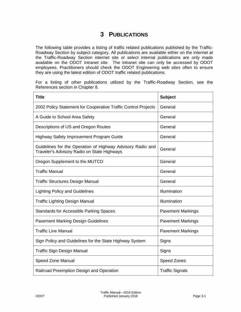
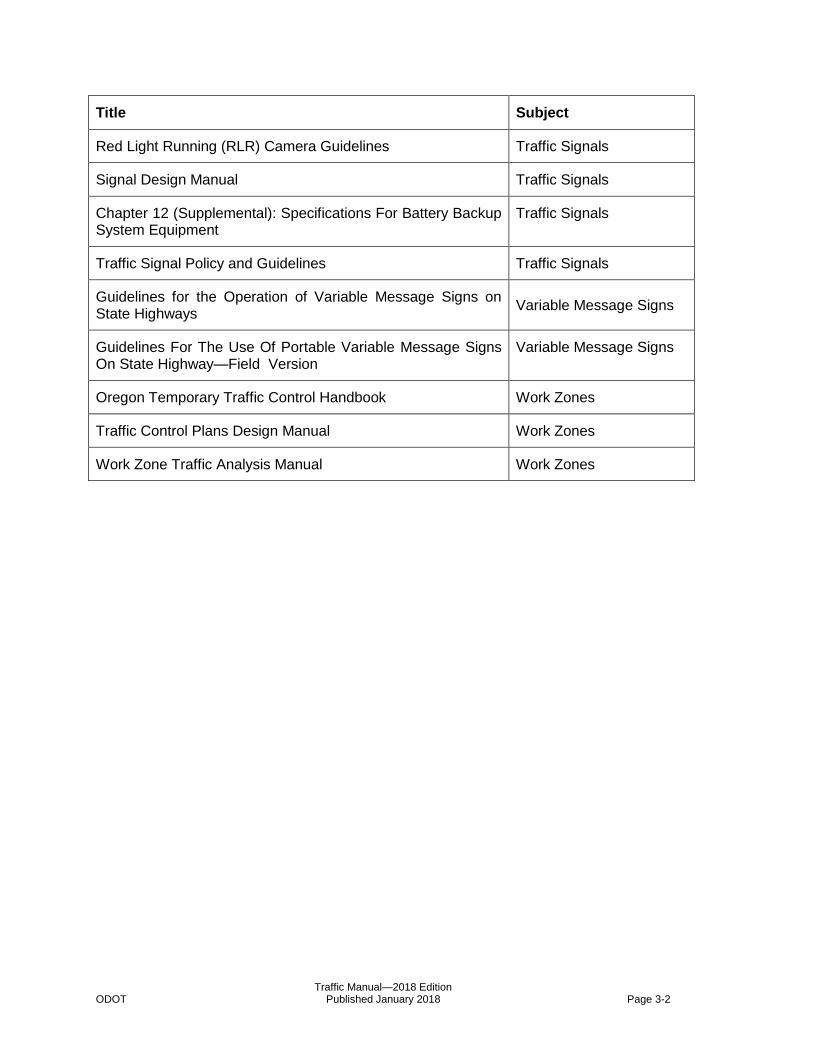
3 PUBLICATIONS
The following table provides a listing of traffic related publications published by the Traffic-Roadway Section by subject category. All publications are available either on the internet at the Traffic-Roadway Section internet site or select internal publications are only made available on the ODOT intranet site. The intranet site can only be accessed by ODOT employees. Practitioners should check the ODOT Engineering web sites often to ensure they are using the latest edition of ODOT traffic related publications.
For a listing of other publications utilized by the Traffic-Roadway Section, see the References section in Chapter 8.
Title Subject
2002 Policy Statement for Cooperative Traffic Control Projects General
A Guide to School Area Safety General
Descriptions of US and Oregon Routes General
Highway Safety Improvement Program Guide General
Guidelines for the Operation of Highway Advisory Radio and Traveler's Advisory Radio on State Highways
General
Oregon Supplement to the MUTCD General
Traffic Manual General
Traffic Structures Design Manual General
Lighting Policy and Guidelines Illumination
Traffic Lighting Design Manual Illumination
Standards for Accessible Parking Spaces Pavement Markings
Pavement Marking Design Guidelines Pavement Markings
Traffic Line Manual Pavement Markings
Sign Policy and Guidelines for the State Highway System Signs
Traffic Sign Design Manual Signs
Speed Zone Manual Speed Zones
Railroad Preemption Design and Operation Traffic Signals
Traffic Manual—2018 Edition ODOT Published January 2018 Page 3-2
Title Subject
Red Light Running (RLR) Camera Guidelines Traffic Signals
Signal Design Manual Traffic Signals
Chapter 12 (Supplemental): Specifications For Battery Backup System Equipment
Traffic Signals
Traffic Signal Policy and Guidelines Traffic Signals
Guidelines for the Operation of Variable Message Signs on State Highways
Variable Message Signs
Guidelines For The Use Of Portable Variable Message Signs On State Highway—Field Version
Variable Message Signs
Oregon Temporary Traffic Control Handbook Work Zones
Traffic Control Plans Design Manual Work Zones
Work Zone Traffic Analysis Manual Work Zones

Traffic Manual—2018 Edition ODOT Published January 2018 Page 4-1
4 TRAFFIC ENGINEERING AND OPERATIONS TEAMS
The Traffic-Roadway Section provides expert staff and administrative support to several teams in specific traffic engineering disciplines on the local, regional, state, and national levels.
4.1 AASHTO Committees
Leader: AASHTO
Membership: varies
Focus: The Traffic-Roadway Section staff participates in two American Association of State Highway and Transportation Officials (AASHTO) committees.
4.1.1 Standing Highway Committee, Subcommittee on Traffic Engineering
Member: State Traffic-Roadway Engineer
Schedule: varies
4.1.2 Subcommittee on System Operations and Management
Member: ITS Unit Manager
Schedule: varies
4.2 Forest Highway Tri-Agency Committee
Leader: Federal Highway Administration, Federal Lands Division
Membership: State Traffic-Roadway Engineer representing ODOT and the Oregon Association of Counties; representatives from the US Forest Service and the Federal Lands Division of FHWA. Also attending the meetings are the Forest Highway (& Enhancement) Program Coordinator as well as representatives from AOC, and staff from FHWA and USFS.
Focus: This group is the authority that decides how the approximately $18 million in Federal Forest Highway money is spent in Oregon.
Schedule: Annual meetings plus supplemental meetings as needed.
4.3 Highway Safety Engineering Committee
Leader: State Traffic-Roadway Engineer
Membership: Traffic-Roadway Section staff, Roadway Manager, Region Traffic Manager(s), FHWA, Safety Division staff
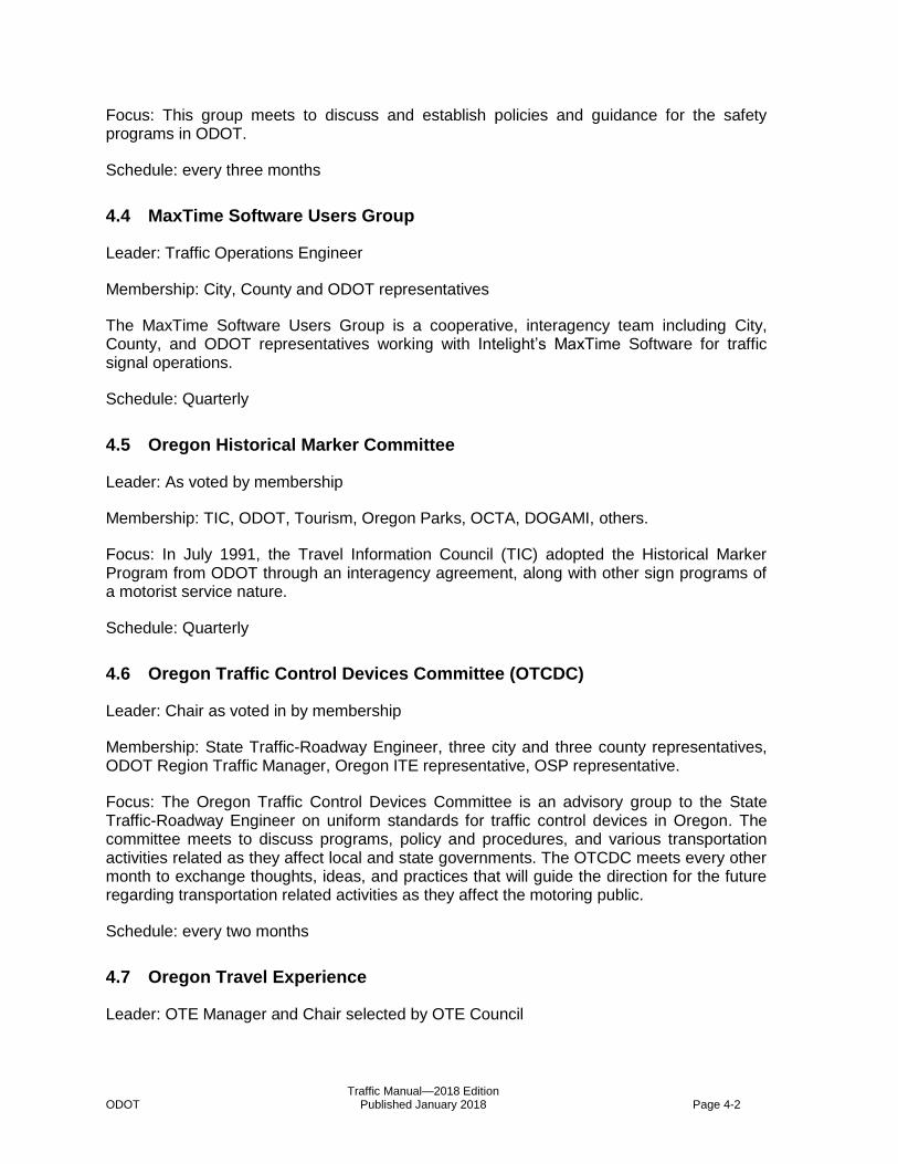
Traffic Manual—2018 Edition ODOT Published January 2018 Page 4-2
Focus: This group meets to discuss and establish policies and guidance for the safety programs in ODOT.
Schedule: every three months
4.4 MaxTime Software Users Group
Leader: Traffic Operations Engineer
Membership: City, County and ODOT representatives
The MaxTime Software Users Group is a cooperative, interagency team including City, County, and ODOT representatives working with Intelight’s MaxTime Software for traffic signal operations.
Schedule: Quarterly
4.5 Oregon Historical Marker Committee
Leader: As voted by membership
Membership: TIC, ODOT, Tourism, Oregon Parks, OCTA, DOGAMI, others.
Focus: In July 1991, the Travel Information Council (TIC) adopted the Historical Marker Program from ODOT through an interagency agreement, along with other sign programs of a motorist service nature.
Schedule: Quarterly
4.6 Oregon Traffic Control Devices Committee (OTCDC)
Leader: Chair as voted in by membership
Membership: State Traffic-Roadway Engineer, three city and three county representatives, ODOT Region Traffic Manager, Oregon ITE representative, OSP representative.
Focus: The Oregon Traffic Control Devices Committee is an advisory group to the State Traffic-Roadway Engineer on uniform standards for traffic control devices in Oregon. The committee meets to discuss programs, policy and procedures, and various transportation activities related as they affect local and state governments. The OTCDC meets every other month to exchange thoughts, ideas, and practices that will guide the direction for the future regarding transportation related activities as they affect the motoring public.
Schedule: every two months
4.7 Oregon Travel Experience
Leader: OTE Manager and Chair selected by OTE Council
Traffic Manual—2018 Edition ODOT Published January 2018 Page 4-3
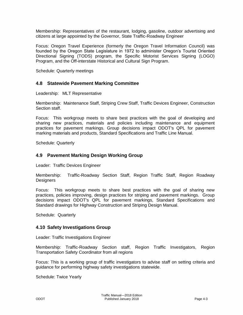
Membership: Representatives of the restaurant, lodging, gasoline, outdoor advertising and citizens at large appointed by the Governor, State Traffic-Roadway Engineer
Focus: Oregon Travel Experience (formerly the Oregon Travel Information Council) was founded by the Oregon State Legislature in 1972 to administer Oregon’s Tourist Oriented Directional Signing (TODS) program, the Specific Motorist Services Signing (LOGO) Program, and the Off-interstate Historical and Cultural Sign Program.
Schedule: Quarterly meetings
4.8 Statewide Pavement Marking Committee
Leadership: MLT Representative
Membership: Maintenance Staff, Striping Crew Staff, Traffic Devices Engineer, Construction Section staff.
Focus: This workgroup meets to share best practices with the goal of developing and sharing new practices, materials and policies including maintenance and equipment practices for pavement markings. Group decisions impact ODOT's QPL for pavement marking materials and products, Standard Specifications and Traffic Line Manual.
Schedule: Quarterly
4.9 Pavement Marking Design Working Group
Leader: Traffic Devices Engineer
Membership: Traffic-Roadway Section Staff, Region Traffic Staff, Region Roadway Designers
Focus: This workgroup meets to share best practices with the goal of sharing new practices, policies improving, design practices for striping and pavement markings. Group decisions impact ODOT's QPL for pavement markings, Standard Specifications and Standard drawings for Highway Construction and Striping Design Manual.
Schedule: Quarterly
4.10 Safety Investigations Group
Leader: Traffic Investigations Engineer
Membership: Traffic-Roadway Section staff, Region Traffic Investigators, Region Transportation Safety Coordinator from all regions
Focus: This is a working group of traffic investigators to advise staff on setting criteria and guidance for performing highway safety investigations statewide.
Schedule: Twice Yearly

Traffic Manual—2018 Edition ODOT Published January 2018 Page 4-4
4.11 Signal Timers Group
Leader: Traffic Operations Engineer
Membership: Traffic-Roadway Section staff, signal timing staff from all regions
Focus: This group meets to discuss traffic signal timing and operations.
Schedule: Quarterly
4.12 Speed Zone Review Panel
Leader: State Traffic-Roadway Engineer designates the Chairperson
Membership: County, City, ODOT, State Police, Safety representative and State Traffic-Roadway Engineer as Secretary.
Focus: The Speed Zone Review Panel (SZRP) reviews contested speed zone cases. The panel receives testimony from the local road authority and makes the final recommendation. The panel is comprised of representatives from the Oregon Transportation Safety Committee, the Oregon State Police, the Association of Oregon Counties, the League of Oregon Cities, and the Department of Transportation.
Schedule: as needed
4.13 Statewide Grant Review Committee
Leader: State Traffic-Roadway Engineer
Membership: State Traffic-Roadway Engineer, District Manager or Permit Specialist, ROW representative, Access Management Engineer, Roadway Representative, Traffic Investigation Engineer, others as needed.
Focus: The Statewide Grant Review Committee (SGRC) reviews applications for grants of access to State Highways.
Schedule: as needed
4.14 Traffic Control Plans Discipline Group
Leader: TCP Engineer
Membership: TCP Designers in each of the five Tech Centers and the two TCP Engineers in Salem
Focus: The function of this Team would be to solidify the design practices being used by the TCP Designers in the Regions. The team would be able to focus on Design Standards, Specifications, Special Provisions, Standard Drawings, Cost Estimating details, Traffic Control Devices on the ODOT Qualified Products List (QPL) and other Temporary Traffic Control issues germane to the development of ODOT Traffic Control Plans.
Traffic Manual—2018 Edition ODOT Published January 2018 Page 4-5
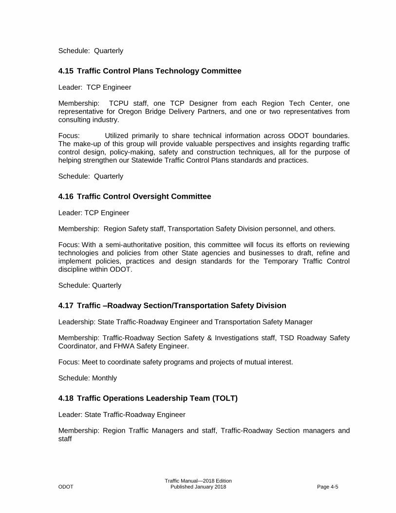
Schedule: Quarterly
4.15 Traffic Control Plans Technology Committee
Leader: TCP Engineer
Membership: TCPU staff, one TCP Designer from each Region Tech Center, one representative for Oregon Bridge Delivery Partners, and one or two representatives from consulting industry.
Focus: Utilized primarily to share technical information across ODOT boundaries. The make-up of this group will provide valuable perspectives and insights regarding traffic control design, policy-making, safety and construction techniques, all for the purpose of helping strengthen our Statewide Traffic Control Plans standards and practices.
Schedule: Quarterly
4.16 Traffic Control Oversight Committee
Leader: TCP Engineer
Membership: Region Safety staff, Transportation Safety Division personnel, and others.
Focus: With a semi-authoritative position, this committee will focus its efforts on reviewing technologies and policies from other State agencies and businesses to draft, refine and implement policies, practices and design standards for the Temporary Traffic Control discipline within ODOT.
Schedule: Quarterly
4.17 Traffic –Roadway Section/Transportation Safety Division
Leadership: State Traffic-Roadway Engineer and Transportation Safety Manager
Membership: Traffic-Roadway Section Safety & Investigations staff, TSD Roadway Safety Coordinator, and FHWA Safety Engineer.
Focus: Meet to coordinate safety programs and projects of mutual interest.
Schedule: Monthly
4.18 Traffic Operations Leadership Team (TOLT)
Leader: State Traffic-Roadway Engineer
Membership: Region Traffic Managers and staff, Traffic-Roadway Section managers and staff
Traffic Manual—2018 Edition ODOT Published January 2018 Page 4-6
Focus: Region Traffic Managers/Engineers from each ODOT Region meet with Traffic-Roadway Section staff and the State Traffic-Roadway Engineer to discuss traffic issues, concerns and operations.
Schedule: Bimonthly
4.19 Traffic Sign Design Working Group
Leader: Sign Engineer
Membership: Traffic-Roadway Section Staff, Region Traffic Sign Design Staff
Focus: This workgroup meets to share best practices with the goal of sharing new practices, policies improving, design practices for traffic signs. Group decisions impact ODOT's QPL for Sign Materials, Standard Specifications and Standard drawings for Highway Construction and Traffic Sign Design Manual.
Schedule: Quarterly
4.20 Traffic Signal Design Working Group
Leader: Traffic Signal Engineer
Membership: Traffic-Roadway Section Staff, Region Traffic Signals Design Staff, Region Traffic Signal Operations Staff (Optional)
Focus: This workgroup meets to share best practices with the goal of sharing new practices, policies improving, design practices for traffic signal systems. Group decisions impact ODOT's QPL for traffic signal equipment (also known as “Blue Sheets”), Standard Specifications and Standard Drawings for Highway Construction and Traffic Signal Design Manual.
Schedule: Quarterly
4.21 TransPort Committee
Leader: Co-Chaired by ODOT and Metro
Member Agencies: ODOT, Clackamas County, Multnomah County, Washington County, City of Portland, Tri-Met, Metro (non-voting).
Key Stakeholder Agencies: City of Gresham, City of Beaverton, Port of Portland, City of Vancouver, Portland State University, FHWA, City of Hillsboro, City of Lake Oswego, City of Tigard, City of Willsonville, City of Vancouver, Clark County WA, C-Tran, RTC, and WSDOT.
Focus: This committee provides a forum for ITS planning and deployment across the agencies in the Portland metropolitan area. ODOT Region 1 staff serves as primary committee members, with statewide ITS staff and Traffic-Roadway staff providing technical support and guidance as needed.

Traffic Manual—2018 Edition ODOT Published January 2018 Page 4-7
Schedule: Monthly
4.22 Traffic Structures Design Working Group
Leader: Traffic Structures Engineer
Membership: Traffic-Roadway Section Staff, Region Traffic Staff, Region Bridge Designers
Focus: This workgroup meets to share best practices with the goal of sharing new practices, policies improving, design practices for Traffic Structures. Group decisions impact ODOT's Standard Specifications and Standard drawings for Highway Construction and Traffic Structures Design Manual.
Schedule: Quarterly


Traffic Manual—2018 Edition ODOT Published January 2018 Page 5-1
5 DELEGATED AUTHORITY
Traffic-Roadway Section staff review field investigations and make recommendations to the State Traffic/Roadway Engineer concerning items of delegated authority. The Delegated Authorities of the State Traffic/Roadway Engineer are derived from Delegation Order TSB 05 dated May 1, 2011 which authorizes the State Traffic/Roadway Engineer to act on the behalf of the Chief Engineer and OAR 734-020-0410 which delegates the authority to approve the installation of traffic control devices on state highways to the State Traffic-Roadway Engineer.1 These responsibilities may require consultation with various individuals or groups to provide expert or professional advice on the matter prior to a final decision by the State Traffic-Roadway Engineer.
5.1 Delegated Authorities of the State Traffic-Roadway Engineer
The State Traffic-Roadway Engineer has been delegated the authority to approve the installation of traffic control devices on state highways by the Oregon Transportation Commission.2 This includes the installation of all new signals, selected modifications to existing signals, and installation of any other traffic control device on state highways.
The following subsections detail the specific Delegated Authorities of the State Traffic-Roadway Engineer. Since traffic signals and ITS devices are more complex types of traffic control devices, they are dealt with in separate subsections at the end of this chapter. The list of delegated authorities is regularly reviewed by Traffic-Roadway Section staff and the Traffic Operations Leadership Team for consistency with Oregon Revised Statutes (ORS), Oregon Administrative Rules (OAR), and Delegation Orders from the Oregon Transportation Commission. The list is revised and updated on an as-needed basis following consultation with the Traffic Operations Leadership Team.
5.1.1 Traffic Control Devices
All delegated authority requests for State Traffic-Roadway Engineer approval should follow roughly the same process for approval:
1. Consultation with the Region Traffic Engineer; and
2. A request sent through the Region Traffic Manager/Engineer with supporting documentation.
5.1.1.1 State Traffic-Roadway Engineer Authority
The following is a list of items that require approval by the State Traffic-Roadway Engineer for use on state highways:
Colored Pavements
Crosswalk Closures and Removals3
Dual Right or Left Turn Lanes
Traffic Manual—2018 Edition ODOT Published January 2018 Page 5-2
Freeway Median Crossovers4
Marked Crosswalks5
Multiway Stop Applications6
One-way Operation for Trucks and Buses7
PREPARE TO STOP WHEN LIGHTS FLASH Sign Applications
Right-Turn Permitted Without Stopping (RTPWS)
Roundabouts
Rumble Strips—Transverse (see 6.28.3 for which applications of Transverse Rumble Strips must be approved by the State Traffic-Roadway Engineer; see Section 6.28 for approval requirements for longitudinal rumble strips).
School Crossings8
Speed Zones—Permanent, Emergency, Construction, Temporary, and School Areas on State Highways 9
STOP Sign Applications on State Highway10
Through Highways at Intersections of the State Highway11
Traffic Signals—Traffic Signal Approval Process, Portable, Modifications (see 5.1.2.3 for a list of modifications that must be approved by the State Traffic-Roadway Engineer), Temporary, or Removal12
Transit Exceptions to Turn Lanes
Truck Routes and Truck Prohibitions
Turn Lanes—Multiple Turn Lanes, Right-Turn Lanes (see 6.39 for a list of conditions that must be approved by the State Traffic-Roadway Engineer), Shared (or combined) Bike and Right-Turn Lane
Turn Prohibitions13 (see 5.1.2.3 for NO TURN ON RED prohibitions; see 6.39 for Turn Prohibitions that may be approved by either the Region Traffic Engineer or Region Access Management Engineer consistent with Oregon Administrative Rules)
UNMUFFLED ENGINE BRAKING PROHIBITED signs on State Highways in concurrence with local jurisdiction14
YIELD Sign Applications on State Highway15
Traffic Manual—2018 Edition ODOT Published January 2018 Page 5-3
5.1.1.2 Region Traffic Manager/Engineer Authority
The Region Traffic Manager/Engineer may authorize standard applications of traffic control devices and some modifications to existing traffic control devices, provided the applications are in compliance with the principles outlined in the Manual on Uniform Traffic Control Devices and applicable ODOT policies and guidelines. The following is a list of items that may be authorized by the Region Traffic Manager/Engineer:
Advance Stop Lines (at marked crosswalks)
Bicycle Lanes
Marking Style for Crosswalks approved by State Traffic-Roadway Engineer (Transverse versus Continental)16
Intersection Control Beacon17
Left and Right Turn Lanes at unsignalized intersections
No Passing Zones18
Parking Prohibitions or Restrictions19
Ramp Meters20
Roadway Illumination21
Rumble Strips—Shoulder, Centerline, Transverse (see 6.28.3 for which applications of Transverse Rumble Strips may be approved by the Region Traffic Engineer; see Section 6.28 for approval requirements for longitudinal rumble strips).
Safe Speed on Curves
Speed Limit Sign Beacon (see 6.7.3 for specific applications allowed on state highways)
Stop Beacon
STOP Sign Applications on cross streets that are not State Highways
Traffic Signals—Modifications (see 5.1.2.3 for a select list of modifications to existing signals that may be approved by the Region Traffic Engineer)
Turn Lanes—Left-Turn Lanes, Right-Turn Lanes (see 6.39 for a select list of conditions that may be approved by the Region Traffic Engineer)
Turn Prohibitions22 (see 5.1.2.3 for NO TURN ON RED prohibitions; see 6.39 for Turn Prohibitions that may be approved by either the Region Traffic Engineer or Region Access Management Engineer consistent with Oregon Administrative Rules)
Vehicle Speed Feedback Sign

Traffic Manual—2018 Edition ODOT Published January 2018 Page 5-4
Warning Beacon
Wrong Way Treatments
YIELD Sign Applications on cross streets that are not State Highways
5.1.2 Traffic Signals and Bicycle/Pedestrian Activated Warning Systems
Traffic signals and bicycle/pedestrian activated warning systems including those in projects approved by the Oregon Transportation Commission (OTC) require State Traffic-Roadway Engineer approval. Approval of locations for such devices is not covered by the OTC’s approval of a STIP project or any other project that is part of a special funding package.23 Any requests for new installations must be reviewed by Traffic-Roadway Section staff and approved by the State Traffic-Roadway Engineer. This provides statewide consistency and assures that the installation of the traffic signal or bicycle/pedestrian activated warning system will improve overall safety and operation of the highway.
5.1.2.1 New Traffic Signal Installations
On major projects, when a project team considers signalization, the Transportation Planning Analysis Unit is contacted to do a preliminary analysis of the projected warrants for a traffic signal. The Transportation Planning Analysis Unit should forward a copy of the warrants and any analysis to the Traffic-Roadway Section as well as the project team. This will provide notice to the Traffic-Roadway Section and provide an early opportunity to identify relevant issues. When the project team decides to recommend a signal on a project, a request should be sent through the Region Traffic Manager, requesting the approval of the State Traffic-Roadway Engineer.
The request should contain the information on the projected warrants, a plan showing the location of proposed traffic signals, safety concerns, planning issues, etc. Any Region Traffic Manager’s concerns should be resolved within the project team environment. Traffic signals approved by the State Traffic-Roadway Engineer are subject to conditions noted on the approval. The Traffic-Roadway Section will maintain the Traffic Signal Approval List.
Applications for new traffic signal installations should follow the procedure outlined in the Oregon Administrative Rules24.
5.1.2.2 New Bicycle/Pedestrian Activated Warning System Installations
On any project where bicycle/pedestrian warning system devices are being considered, both the Region Traffic Unit and the Traffic-Roadway Section are contacted to do a preliminary analysis of the proposed device location and type of device to be installed. When such devices are recommended for installation, a request should be sent to the Region Traffic Unit which will coordinate with the Traffic-Roadway Section in requesting the approval of the State Traffic-Roadway Engineer.
The following is a list of bicycle/pedestrian activated traffic control devices that require approval by the State Traffic-Roadway Engineer for use on state highways:
Active Warning Signs at Bridges and Tunnels
Traffic Manual—2018 Edition ODOT Published January 2018 Page 5-5
Warning Beacons as supplemental emphasis to the W11-2 Pedestrian sign
Rectangular Rapid Flashing Beacons (RRFB)
In-Roadway Lights
Pedestrian Hybrid Beacon
5.1.2.3 Existing Traffic Signals
Modifications to existing traffic signals on state highways must be approved by either the State Traffic-Roadway Engineer or the Region Traffic Manager/Engineer depending on the type of modification. A “modification” has been interpreted to mean a change in the operational function of a traffic signal and includes the addition or deletion of signal phases, modifications which provide or remove split phase operation, addition of equipment not normally a part of a traffic signal design, and the addition or removal of through vehicle lanes or pedestrian crossings at the intersection. Signal revisions and normal maintenance activities such as the replacement of detectors, poles, or controllers and timing adjustments that don’t affect operation do not constitute a “modification.”
The Traffic Operations Leadership Team maintains a list of items associated with traffic signals that may be approved by either the State Traffic-Roadway Engineer or the Region Traffic Manager/Engineer. The following items remain under the approval authority of the State Traffic-Roadway Engineer:
Bicycle Signal Heads
331B331BCCChannelized Right-Turn Lanes
New approaches to existing signalized intersections
Pedestrian Crosswalks—Addition or removal of crosswalks
Preemption Systems—Emergency Service Providers and Public Transit Authorities authorized to use emergency preemption and bus priority systems25
Split phasing—(i.e. opposing through movements do not operate concurrently)
U-turns at Signalized Intersections26
The following items may be approved by the Region Traffic Engineer/Manager or his/her designee (who shall possess a current Professional Engineer’s license) provided the application is consistent with ODOT standards and practices set forth in the Traffic Signal Policy and Guidelines and the Manual on Uniform Traffic Control Devices. Appropriate documentation must be sent to the Traffic-Roadway Section justifying and explaining the type of modification that is planned.
Audible Pedestrian Signals27
Detection—Loop, Video, etc.
Traffic Manual—2018 Edition ODOT Published January 2018 Page 5-6
Lane use signing at signalized intersections
Lanes—Addition or removal of Left-Turn Lanes, Conventional Right-Turn Lanes, or through lanes at signalized intersections
Left and right turn phase modifications except split phasing
NO TURN ON RED signs28
Pedestrian pedestals
Pedestrian push buttons—Move or relocate (see Signal Design Manual for latest provisions and requirements on pedestrian signal equipment layout).
Overlap phasing
Preemption Systems—Addition or removal of emergency preemption and bus priority systems at existing traffic signals based on previous approval of a local Emergency Service Provider or Public Transit Authority by the State Traffic-Roadway Engineer to use such systems
Signal heads—Change out protected left green arrow only to all arrow, Move or realign, Programmed, Supplemental
Signal poles—Replacement
Work zone modifications—Phasing, Signal head locations, etc.
The State Traffic-Roadway Engineer retains the authority to require modifications to any traffic control device, including traffic signals, when deemed necessary for the safety of highway users.
5.1.3 Intelligent Transportation System Devices
ITS devices associated with traffic control require State Traffic-Roadway Engineer approval. Approval of new ITS device locations are not covered by the Oregon Transportation Commission’s approval of STIP projects or any other special funding package approved by the OTC. All ITS traffic control device requests and design plans must be reviewed by both Region Traffic Unit and Intelligent Transportation Systems Unit staff and approved by the State Traffic-Roadway Engineer. This provides statewide consistency and assures that the installation of the ITS device will integrate into the Department’s ITS architecture.
On any project where ITS traffic control devices are being considered, both the Region Traffic Unit and Intelligent Transportation Systems Unit are contacted to do a preliminary analysis of the proposed device location and type of device to be installed. When an ITS traffic control device is recommended for installation, a request should be sent to the Region Traffic Unit which will coordinate with the Intelligent Transportation Systems Unit in requesting the approval of the State Traffic-Roadway Engineer. Only requests forwarded with concurrence of both the Region Traffic Unit and the Intelligent Transportation Systems Unit will be considered for State Traffic-Roadway Engineer Approval.
Traffic Manual—2018 Edition ODOT Published January 2018 Page 5-7
5.1.3.1 State Traffic-Roadway Engineer Authority
The following is a list of ITS traffic control devices that require approval by the State Traffic-Roadway Engineer for use on state highways:
Curve warning systems
Gates (automatically-operated for closing roadways due to weather events such as snow, ice, or flooding, or for other emergencies)
Highway Advisory Radio29
Road condition warning systems with active signing (i.e. ice warning, flood warning, etc.)
Variable Message Signs30
Variable Speed Limit Signs
5.1.3.2 Region Traffic Manager/Engineer Authority
The Region Traffic Manager/Engineer may authorize special applications of some ITS traffic control devices but only after consultation with the Intelligent Transportation Systems Unit and receiving concurrence on applicable design standards and how the device will integrate into the Department’s ITS architecture. The following is a list of ITS traffic control devices and operations that may be authorized by the Region Traffic Manager/Engineer:
Messages other than PSA’s on VMS31
File Code: COM 04
1 Refer to Section 7.6 in Traffic Manual
2 Refer to OAR 734-020-0410
3 Refer to Traffic Line Manual, Section B-15
4 Refer to OAR 734-020-0100 through 0115
5 Refer to Section 6.6.1 in Traffic Manual; Traffic Line Manual
6 Refer to MUTCD, Section 2B.07
7 Refer to OAR 734-020-0125 and 0130
8 Refer to A Guide to School Area Safety
9 Refer to Speed Zone Manual; OAR 734-020-0015; A Guide to School Area Safety
10 Refer to MUTCD, Sections 2B.04 through 2B.07

Traffic Manual—2018 Edition ODOT Published January 2018 Page 5-8
11 Refer to ORS 810.110
12 Refer to ODOT Traffic Signal Policy and Guidelines; OAR 734-020-0400 through 0500
13 Refer to OAR 734-020-0020
14 Refer to ODOT Sign Policy and Guidelines
15 Refer to MUTCD, Sections 2B.08 through 2B.10
16 Refer to Section 6.6.2.6 in Traffic Manual
17 Refer to MUTCD, Section 4K.02
18 Refer to MUTCD, Section 3B.02; Section 6.23.3 in Traffic Manual
19 Refer to OAR 734-020-0020 and 0080 through 0090
20 Refer to Section 6.35.2.8 in Traffic Manual
21 Refer to ODOT Lighting Policy and Guidelines
22 Refer to OAR 734-020-0020
23 Refer to OAR 734-020-400 through 734-020-500
24 Refer to OAR 734-020-400 through 734-020-500
25 Refer to ODOT Traffic Signal Policy and Guidelines
26 Refer to OAR 734-020-0025
27 Refer to ODOT Traffic Signal Policy and Guidelines; OAR 734-020-0400 through 0500
28 Refer to ODOT Sign Policy & Guidelines
29 Refer to ODOT Guidelines for the Operation of Highway Advisory Radio
30 Refer to ODOT Guidelines for the Operation of Variable Message Signs
31 Refer to ODOT Guidelines for the Operation of Variable Message Signs on State Highways

Traffic Manual—2018 Edition ODOT Published January 2018 Page 6-1
6 TRAFFIC ENGINEERING PRACTICES
6.1 Access Management
6.1.1 Overview
Access Management is a comprehensive approach for improving safety and efficiency of traffic operations on transportation facilities, while providing statewide accessibility and mobility. Access management necessitates that a logical, functional hierarchy of all roads in the state be established; that hierarchy should then be reinforced by applying various levels of access management. The Intermodal Surface Transportation Efficiency Act (ISTEA) of 1991 established strong national policy support for the consideration of access management in congestion management and corridor preservation. Standards are established for the different classes of roads in design characteristics such as:
freeway/highway access management
interchange spacing
spacing and control of median openings
signal spacing
intersection spacing
driveway spacing and consolidation
provision of turn lanes, and acceleration and deceleration lanes
These standards usually reflect land-zoning regulations. Implementation of access management has the effect of separating and reducing conflicts, and thereby reducing the likelihood of traffic crashes. The provision of turn lanes removes decelerating vehicles from the traffic stream thus reducing rear-end crashes, and enabling the rest of the traffic stream to flow with less interruption. Consistent interchange spacing (together with full access control) helps ensure driver expectancy and reduces the turbulence caused by merging and diverging freeway traffic. Nationwide, access management has proven to:
reduce crashes,
reduce delays,
reduce travel times and fuel consumption,
help improve traffic signal progression by helping to maintain travel speeds,
Traffic Manual—2018 Edition ODOT Published January 2018 Page 6-2
reduce congestion and environmental pollution, and help meet Congestion Management and Air Quality (CMAQ) goals,
increase capacities of various types of facilities,
improve local economies by improving accessibility to businesses and
expanding their market areas, and
reduce the urgency and pressure on local governments to build more roads to balance the effects of mismanagement of the existing facilities.
6.1.1.1 Criteria
Criteria for the Access Management policies and guidelines are covered in the Oregon Highway Plan and Chapter 734, Division 51 of the Oregon Administrative Rules.
Region Access Management Engineers (RAMEs) play a lead role in individual projects and the development review process. Providing key technical support for access management standards, the RAMEs provide a communication link between central staff and region staff.
They also act as an ODOT advisory group along with central staff on access management issues, reviewing standards, policies and practices and making recommendations.
The Traffic-Roadway Section plays a significant role in the determination of access management standards, with representation on various technical committees as well as oversight of the grants of access process. The Traffic-Roadway Section also ensures that access management standards are met by its involvement in the approval and design of traffic signals and other traffic control devices, lane configurations, U-turns, freeways, interchanges, etc. Review of traffic impact analyses provides the Traffic-Roadway Section an opportunity to determine the effects of new signals on traffic signal progression, check for adequate traffic storage and sight distances, and ensures designs that comply with the access management standards for the class of road facility. Such reviews also ensure the needs of transit, pedestrians, and bicyclists are included in the site and vicinity design.
6.1.2 Grants of Access
A Grant of Access is required to create a new approach where no right of access (access control) exists between the highway and a portion or all of a property abutting the highway.
The issues surrounding the applications for grants of access can be complex. The State Traffic-Roadway Engineer chairs a centralized review committee, the Statewide Grant Review Committee (SGRC), with representatives from various disciplines within ODOT. The role of the committee is to provide consistent and fair decisions across the state, decisions that protect Oregon’s Highway system and are also in the best interests of the traveling public. (See also OAR 734-051-2020)
When an application for an approach to a State Highway is received, ODOT must determine if an approach (either public or private) is legally permissible and if it meets established

Traffic Manual—2018 Edition ODOT Published January 2018 Page 6-3
policies. If it is determined that the approach is in an area where an approach would not violate established policies but has no legal right of access to the highway, an application for a grant of access may be filed. To approve a grant of access ODOT must either determine that access control is no longer necessary or that the approach would benefit the State Highway System. For safety and operational reasons, breaking access control for grants of access is generally difficult to justify.
6.2 Active Warning Signs at Bridges and Tunnels
6.2.1 Background
The Department has installed active warning signs at the entrance to tunnels and on narrow bridge approaches at specific locations on state highways that meet the Criteria and Considerations listed in this section. Standard designs for these active warning signs are maintained in the Sign Policy and Guidelines for the State Highway System. The signs have Flashing Beacons that are activated when bicyclists push a button as they enter the tunnel or cross the bridge. The device is timed for the average cyclist to travel the required distance before the beacons stop flashing. The signs are popular with both drivers and bicyclists. Tunnel applications have been fairly limited due to the low number of tunnels on state highways in Oregon. Requests for applications on narrow bridges have been more frequent in recent years. However, there has been concern over the widespread application of these devices on bridges since Oregon has many bridges and this could represent significant installation and maintenance costs (from $5,000 to more than $20,000 for each).
6.2.2 Criteria
The following criteria have been developed to help guide decision-makers when a request for application to a bridge must be considered. An active warning system for bicyclists on a bridge should be considered when an engineering study demonstrates their need and the location meets the following criteria:
1. There are inadequate shoulders or separation from traffic:
a. For Bicyclists: the shoulders less than 4 feet
b. Other situations where motor vehicles may encroach on bicycle space
2. There is demonstrated bicycle or pedestrian usage (at least 10 pedestrians and/or bicycles per hour for any four hours of the day is the minimum threshold suggested).
3. The public support has been demonstrated by a request from a local government body.
4. There is no other available/practical/safe route, or one cannot be provided at a reasonable cost.
5. Operational techniques (e.g. signing, restriping) cannot improve the situation, or construction measures are not practical or too expensive (e.g. removing fellow guard, adding sidewalks or providing a separate bridge).

Traffic Manual—2018 Edition ODOT Published January 2018 Page 6-4
6. A combination of the following criteria create traffic conditions unacceptable to pedestrians and/or cyclists on the bridge:
a. Speed;
b. ADT (include percentage of trucks, and peak hour, when pedestrians and/or bicyclists may be using the bridge);
c. Sight distance; and
d. Length of bridge.
7. Funding and maintenance have been agreed upon between the District and/or locals as to who will pay for maintenance and power.
6.2.3 Considerations
If all the above conditions are met, consider the following factors when providing a flashing warning system:
1. Historic character of bridge – many older narrow bridges are classified as historic, and the placement of a large warning sign may have a negative aesthetic impact; contact Environmental Section as needed.
2. Placement of sign – can it be placed in such a way that it is visible to motorists for them to adequately see, understand, react and adjust their speed? For Freight Routes in the Oregon Highway Plan (OHP), strong consideration should be given to mounting the sign overhead on a mast arm for bridges or above the tunnel portal to enhance visibility of the sign. If overhead mounting is not possible, then dual signs on opposite sides of the highway should be considered. For other routes, a single sign mounted on the side of the highway may be used.
3. Placement of push button – can they be placed in such a way that pedestrians and/or cyclists can access them easily and see that the warning lights have been activated?
4. For pedestrians – will they be crossing the bridge on either side, coming from both directions? If so, push buttons should be placed in all four quadrants at the bridge ends.
5. Beyond the bridge, do pedestrians and/or cyclists have safe and convenient access to the approach roads? This is especially applicable to freeway interchanges and bridges that terminate at intersections.
6. Local education of the pedestrian and/or bicyclists on the meaning and use of the devices may be needed.
6.2.4 Engineering Study
The Region Traffic Unit should conduct an investigation and analysis of the criteria and considerations as well as any other pertinent information. Written documentation of the investigation as well as a recommendation should be provided. Preliminary design plans
Traffic Manual—2018 Edition ODOT Published January 2018 Page 6-5
detailing proposed locations of signs, push buttons, and electrical connections should be submitted to the Traffic-Roadway Section for review by the State Traffic Signal Engineer. Support of the Region Traffic Unit and approval of the State Traffic-Roadway Engineer under the Delegated Authorities of the State Traffic-Roadway Engineer is required before installation of the signs.
6.3 Bicycle Facilities
The Department of Transportation has adopted the AASHTO publication, Guide for the Development of Bicycle Facilities, to establish bikeway design and construction standards, to establish traffic control devices guidelines for bikeways, and recommend illumination standards. Bicycle facilities are covered by OAR 734-020-0055 and OAR 734-020-0060. (Refer also to Sign Policy and Guidelines for the State Highway System, Traffic Line Manual, Oregon Bicycle and Pedestrian Plan, and OAR 734 Division 56.)
File Code: LOC 03
6.3.1.1 Shared (or combined) Bike and Right-Turn Lane
See 6.38.5
6.4 Capacity Analysis
A capacity analysis is required to determine the existing or future quality of operations (level of service) on a part of a transportation system – freeways, rural highways, intersections, etc. Follow the established Analysis Procedures Manual methods to complete a capacity analysis.
Capacity analysis results usually require a decision to be made involving access management issues, construction of a traffic signal, provision of extra lanes, etc. Some of these can only be approved by the State Traffic-Roadway Engineer under a letter of authority from the Technical Services Manager or through Administrative Rule. Requests for approval should include all necessary documentation of a thorough investigation, and a recommendation from the investigator. Requests from the regions to the Traffic-Roadway Section to carry out a capacity analysis should also be addressed to the State Traffic-Roadway Engineer, with all necessary information. Analysis results that influence decisions made at a local level will be returned to the requester. The Traffic-Roadway Section will support the regions on the analysis, but will normally not take the lead in public meetings that involve these investigations.
File Code: TRA 16-07-21
File Code: TRA 03-00-01
6.5 Crash Analysis
6.5.1 Overview
Crash data is used by transportation engineers to identify and analyze high crash locations, evaluate engineering measures and identify trends in crash occurrences to develop
Traffic Manual—2018 Edition ODOT Published January 2018 Page 6-6
solutions that improve safety. The data can be used to develop a better understanding of the performance of traffic control measures or to study specific sites where a safety problem may exist.
When locations are identified for crash analyses the first step is to gather all crash data relevant to the location. Several reports or tools exist to assist in this step (See Crash Analysis Data Sources). These reports allow data to be summarized by different characteristics, such as date and time, roadside culture, weather conditions, type of crash, types of vehicles, and other information. Preparing collision diagrams to identify patterns can assist the analyst in analyzing the situation. Collecting other data such as volumes and operating speeds can also be helpful.
Site visits and video logs can assist with familiarizing the analyst with physical features, roadway geometry and other site characteristics. Crash and fatality rates for the section should be compared to the statewide average for similar types of highways.
When the analyst has identified and completed analysis of the specific site, they can evaluate which corrective actions might be beneficial and cost effective. Several sources exist which are helpful including: Synthesis of Safety Research Related to Traffic Control and Roadway Elements, December 1982 and Safety Effectiveness of Highway Design Features, November 1992, both published by the Federal Highway Administration. The Traffic-Roadway Section routinely performs crash analysis for environmental documents and corridor studies and can help in the evaluation of specific sites or trends. Contact the Highway Safety Engineering Coordinator for assistance.
6.5.2 Crash Analysis Data Sources
The following discussion identifies data sources for crash analysis. The statistical treatment of the data and other reference material is contained in Section 7.4. Crash Analysis is an important traffic engineering tool used to answer questions about road design, maintenance, and operations. Crash analysis can also be used to learn what questions to ask. The choice and arrangement of the data depend heavily upon the nature of the question, availability of pertinent data, and time available.
Crash data sources readily available to ODOT employees include:
6.5.2.1 Oregon Motor Vehicle Traffic Crash Database
This is the main database compiled and maintained by the Crash Analysis and Reporting Unit. It covers all state, county, and city roadways. All crashes reported to DMV and forwarded to the Crash Analysis and Reporting Unit are entered into the database if there is property damage exceeding a minimum dollar amount, or if there are any injuries. This data can be queried directly by the Crash Analysis and Reporting Unit to provide lists that meet very selective criteria.
The most recent ten years of crash data can be accessed on the ODOT Intranet as part of the Oregon Transportation Management System (OTMS).
Traffic Manual—2018 Edition ODOT Published January 2018 Page 6-7
6.5.2.2 Oregon Traffic Crash Summary
This extract from the main database listed above, has been published annually by the Crash Analysis and Reporting Unit of the Transportation Data Section since 1994. Previously, these reports were published by Driver and Motor Vehicle Services Division. These tables provide selected crash tallies for statewide, countywide, and, in some cases, citywide coverage. Subsets for truck, pedestrian, bicycle, and motorcycle crashes were published until 1987. From 1987 to 1996, the subsets were not published, but printouts were provided directly to the Traffic-Roadway Section. Beginning in 1989, additional subsets were generated for crashes on state highways and for fatal crashes only. The Oregon Traffic Crash Summary book has included all the subsets since 1996. A separate publication of crash rates on state highways is also available.
6.5.2.3 Accident Summary Database
This has been produced annually since 1990. This is a database/software combination for use on a desktop computer to generate reports at the request of the user. The summaries generated by this program are frequently helpful because the answers are often sufficient, or time may be too short to permit more detailed analysis. Each set contains three years of simplified crash data for the entire state highway system, plus estimates of traffic volume for each mainline crash site, plus information on SPIS sites. The crash data are extracted from the main database listed above. Traffic volume estimates come from the mileage control tape for the middle year of the three years covered. SPIS numbers are imported and assigned to each rated milepost.
These three-year databases are coupled with a summary program to produce a summary tally that includes an estimate of the crash rate and traffic volume for the selected section. Each summary must be for one continuous portion of one highway for all three years. The estimate of traffic volume is a simple average of all the volume estimates for each crash site. When a short part of the section specified has high volumes and many crashes but the remainder has low volumes and few crashes, the estimated crash rate will be too low. When appropriate, the crash rate should be corrected manually on the face of the printout using a better estimate of overall volume. Alternatively, separate summaries could be generated for each dissimilar segment.
6.5.2.4 TransGIS Mapping Tool
The TransGIS mapping tool was developed in order to provide a graphical method to display Category 1-5 segment information, SPIS locations, crash data, street and road information, and Average Daily Traffic (ADT) information. TransGIS displays this information on a state map. The user can choose the information that is displayed and can zoom into the map to increase detail, as well as display city and county maps behind this data.
6.5.2.5 Crash Graphing Tool
The Crash Graph Tool was created to automatically create graphs and summary tables of ODOT crash data in Microsoft Excel directly from the "Direction (Vehicle)" report from the State Highway Crash Reports on the ODOT Intranet. The tool is a Microsoft Excel Add-in and can be downloaded from the ODOT Intranet. External customers interested in obtaining the Crash Graph Tool should contact the Traffic-Roadway Section Highway Safety Engineering Coordinator for additional information.
Traffic Manual—2018 Edition ODOT Published January 2018 Page 6-8
6.5.2.6 Hardcopies
These have been generated by the Crash Analysis and Reporting Unit over the years for the State Highway System. These books are extracts of data from the main database listed above. Working libraries of these reports are maintained by the Traffic-Roadway Section and other offices. These books contain lists of crash data for one or five years, and lists of various crash rates for one or five years. These books are the normal source of data for those years no longer available directly from the mainframe computer.
6.5.2.7 Crash Rate Tables
These have been published annually by the Crash Analysis and Reporting Unit since at least 1948. Tables in the front of the book list statewide crash rates for several categories of the State Highway System. More tables list the crash rates for selected sections of each state highway, as well as a rural/urban break out. Additional tables list intersection crash data and fatal crash data.
6.5.2.8 Traffic Volume Tables
These have been published annually by the Transportation Data Section since at least 1939. There are no crash data in this book. It contains volume estimates for the entire state highway system. These volumes can be used for calculating crash rates. Information provided for automatic traffic recorders can be used in some instances to learn about seasonal or about weekend vs. weekday crash rates.
File Code: TRA 03-00-01
6.6 Crosswalks
6.6.1 Marked Crosswalks at Uncontrolled Locations on State Highways
6.6.1.1 Policy overview
The Traffic-Roadway Section issued a technical bulletin in April 2006 to provide direction to project delivery teams and District Managers relating to the establishment of marked crosswalks at uncontrolled locations on state highways as part of Statewide Transportation Improvement Program (STIP) and Oregon Transportation Investment Act (OTIA) projects and each District’s pavement marking maintenance program.
6.6.1.2 Definitions of key terms
Uncontrolled location on state highway: A location on the state highway which lacks a STOP sign, YIELD sign, or Traffic Signal for controlling and stopping traffic on the state highway.
6.6.1.3 Background
The Oregon Transportation Commission, through ODOT’s Chief Engineer has delegated the State Traffic-Roadway Engineer with the authority to designate pedestrian crossings on state highways. The Traffic Operations Leadership Team (TOLT) has become concerned that many local agencies have chosen to mark crosswalks across state highways at
Traffic Manual—2018 Edition ODOT Published January 2018 Page 6-9
uncontrolled locations without a proper engineering investigation or review by the Region Traffic Engineer and State Traffic-Roadway Engineer.
Additionally, the increased use of consultants to provide roadway and traffic engineering services has resulted in varying levels of quality in striping plans. Some consultants have produced striping plans placing marked crosswalks across the state highway at all intersections within the project limits regardless of whether an engineering investigation has been conducted or not. Such over-use of crosswalks is a violation of our standard practice, creates a potential liability exposure to the department and creates a definite increase in maintenance costs. The ODOT Traffic Manual provides clear guidance for the conditions in which marked crosswalks at uncontrolled locations should be considered. Locations that do not meet the criteria listed in the manual should be recommended for removal.
6.6.1.4 Responsibilities of Parties Involved
Highway Division personnel such as Project Leaders and Consultant Project Managers, whose duties include project delivery, are expected to coordinate engineering investigations of marked crosswalks at uncontrolled locations with the Region Traffic Engineer to insure timely delivery of project designs. District Managers are expected to verify that the marked crosswalks at uncontrolled locations being maintained by the Region striping crew in their particular District have received proper approval by the State Traffic-Roadway Engineer.
6.6.1.5 Action Required
Project delivery teams shall identify all marked crosswalks at uncontrolled locations during the preliminary scoping process for projects. The project delivery team shall coordinate an engineering investigation with the Region Traffic Engineer. The investigation shall document which marked crosswalks were previously approved by the State Traffic-Roadway Engineer and which new or previously unapproved crosswalks are consistent with the guidelines set forth in the ODOT Traffic Manual. Any previously unapproved marked crosswalks to be included in the project shall be submitted by the Region Traffic Engineer to the State Traffic-Roadway Engineer for consideration of approval.
District Managers or Striping Supervisors should whenever possible identify existing crosswalks in advance of re-striping activities and coordinate with either the Region Traffic Office or the Traffic-Roadway Section to assess whether the crosswalks have been approved and who has the responsibility for maintenance. This will become easier as we continue to build our database of pavement marking information.
6.6.1.6 Implementation
The implementation of this policy will be closely monitored by Traffic-Roadway Section staff and the Traffic Operations Leadership Team comprised of the State Traffic-Roadway Engineer and the Region Traffic Managers from all 5 ODOT Region Technical Centers. Any revisions will be based on feedback from the Region Technical Centers, the Maintenance Leadership Team, and the Traffic Operations Leadership Team.

Traffic Manual—2018 Edition ODOT Published January 2018 Page 6-10
6.6.2 Criteria for Establishing Marked Crosswalks on State Highways
6.6.2.1 Overview
While the Manual on Uniform Traffic Control Devices does not provide any specific warrants for establishing marked crosswalks, the Department has established certain criteria for marking crosswalks across State Highways under various conditions based on information in the Manual on Uniform Traffic Control Devices on recent research conducted by the Transportation Research Board (TRB). Some general criteria include the following:
Marked crosswalks shall be established at all school crossings and across all signalized approaches at intersections, unless the crossing is closed by official action;
Marked crosswalks should be established across all approaches at urban roundabouts;
Marked crosswalks may be established at rural roundabouts, across stop-controlled approaches to intersections, or across channelized right-turn lanes.
In an effort to ensure that marked crosswalks are placed where they are needed, specific engineering studies must be conducted. An engineering study and State Traffic-Roadway Engineer approval is required before establishing marked crosswalks at locations other than signalized approaches at intersections, stop signs, roundabouts, or channelized right turn lanes. The following criteria and considerations are guidelines for assisting in the determination of when a pedestrian crossing should be marked with a crosswalk.
6.6.2.2 Criteria for Marking Crosswalks at Signalized Intersections
Marked crosswalks are required at all signalized approaches of an intersection, unless a traffic engineering investigation shows that a crosswalk should not be allowed and it is closed by official action (See Crosswalk Closures and Removals). Pedestrian signal heads shall be installed unless the crosswalk is closed by official action. Barrier and signs shall be posted for all officially closed crosswalks. All requests for crosswalk closures at signalized intersections on state highways shall include a traffic engineering investigation and require the approval of the State Traffic-Roadway Engineer. The primary reason for closing a crosswalk is safety, however geometric and operational factors may also be considered.
Required
Pedestrian push buttons shall be accessible, preferably from an all-weather level landing. Crosswalks should be marked at channelized turn lanes controlled by a traffic signal or stop sign where there are crosswalks marked across the other controlled approaches. If the turn lane is controlled by a yield sign or uncontrolled, marking of pedestrian crosswalks may still be considered (See Criteria for Establishing Marked Crosswalks on State Highways).
Recommended
When used, a crosswalk across a non-signal controlled channelized right turn lane should be located one car length back (approx. 25 feet) from Yield line, Stop line or gore point of island. This will allow the driver to deal with one conflict at a time. Staggered continental crosswalks may be used across unsignalized turn lanes.
Traffic Manual—2018 Edition ODOT Published January 2018 Page 6-11
Stop lines should not be used with crosswalks at signalized approaches unless it is desirable to stop vehicles in advance of the crosswalk. The crosswalk marking, either standard transverse lines or longitudinal lines (continental style) serve as the indication of where vehicles are required to stop.
6.6.2.3 Criteria for Marking Crosswalks at Uncontrolled Approaches of Intersections
Generally marked crosswalks are discouraged at uncontrolled approaches due to a concern that they may not improve safety and may, if inappropriate, put a pedestrian more at risk. The criteria are primarily restrictions on marking crosswalks in locations that would be potentially hazardous. In situations where the pedestrian volumes justify marking crosswalks (well above minimum threshold levels) additional safety measures (i.e., pedestrian refuges) should be considered above and beyond marking. Installation of a marked crosswalk will not, in and of itself, increase the level of safety for pedestrians. Marked crosswalks should only be considered at uncontrolled approaches when an engineering study demonstrates their need and the location meets the following criteria:
Required
There is good visibility of the crosswalk from all directions, or it can be obtained. Stopping sight distance is a minimum.
There is no reasonable alternative crossing location.
There is established pedestrian usage. Considerations include: volume of pedestrians, opportunity for safe crossing (i.e., sufficient gaps in traffic), percentage of elderly or young children, and the nature of the attraction (See ITE suggested pedestrian volume thresholds in Section 6.6.2.11). Lower pedestrian volumes would be acceptable for areas where there is greater proportion of less experienced and less agile pedestrians (e.g., near schools and/or elderly housing areas)
Posted speeds should be 40 mph or less.
Traffic Volumes should be 10,000 or less ADT. If above 10,000 ADT raised median islands should be included.
On multi-lane highways, pedestrian crossing enhancements (curb extensions and/or pedestrian refuges) should be considered.
6.6.2.4 Criteria for Marking Crosswalks at Mid-Block Locations
Installations of mid-block crosswalks are discouraged for the same reasons uncontrolled approaches are discouraged.
Mid-block crosswalks often do not get good compliance from motorists. Only consider mid-block crosswalks when an engineering study demonstrates their need and the location meets the following criteria:

Traffic Manual—2018 Edition ODOT Published January 2018 Page 6-12
Required
There is good visibility of the crosswalk from all directions or it can be obtained. Stopping sight distance is a minimum.
Posted vehicular speeds should be 40 mph or less.
There is not a reasonable alternative at a stop-controlled intersection.
There is established pedestrian usage. Considerations include: volume of pedestrians, opportunity for safe crossing (i.e., sufficient gaps in traffic), percentage of elderly or young children, and the nature of the attraction (see ITE suggested pedestrian volume thresholds in Section 6.6.2.11). Lower pedestrian volumes would be acceptable for areas where there is greater proportion of less experienced and less agile pedestrians (e.g. near schools and/or elderly housing areas).
Locations should be more than 300 feet to nearest crossing or marked crosswalk.
Traffic Volumes should be less than 10,000 ADT or if above 10,000 ADT raised median islands should be included.
Pedestrian crossing enhancements (curb extensions and/or pedestrian refuges) should be considered.
Optional
Where a marked crosswalk can concentrate or channelize multiple pedestrian crossings to a single location.
Free turning movements or other operational considerations inhibit pedestrian crossing opportunities at the nearest intersection.
Established bus stops where riders need access to the opposite side of road from the bus stop where the stop can’t be relocated.
6.6.2.5 Criteria for Marking School Crossings at Uncontrolled Locations
When establishing marked school crossings across uncontrolled locations the applicable criteria for marking crosswalks should be followed. Generally school crossings are established based on School Route Plans and are sited to take advantage of existing traffic controls such as traffic signals. Where existing traffic controls are not available and it is not feasible to require children to walk out of direction a marked crosswalk may be established. The number and age of the students using the crossing should be taken into consideration. Adult crossing guards should be considered for established school crossings at uncontrolled locations where gaps are not sufficient to permit a reasonably safe crossing.
6.6.2.6 Marking Styles
Continental crosswalk markings (referred to as “Longitudinal” markings in the MUTCD) should be used for all marked crosswalks on uncontrolled approaches, yield controlled
Traffic Manual—2018 Edition ODOT Published January 2018 Page 6-13
approaches, midblock locations roundabouts, unsignalized approaches of channelized right turn lanes, and all crossings employing rectangular rapid flashing beacons.
Continental crosswalk markings are the preferred style on uncontrolled approaches because they have been shown to be visible from a significantly greater distance than transverse crosswalk markings. (Crosswalk Marking Field Visibility Study, FHWA Publications No. HRT-10-068.) The added visibility of continental markings can help address the vulnerability of pedestrians at uncontrolled crosswalks where drivers are not already required to stop like they would at an intersection controlled by a traffic signal or stop sign. While continental crosswalk markings require more material and labor to install, they will typically not require remarking as often as transverse crosswalk markings. Maintenance needs can be minimized by staggering the longitudinal bars to avoid the wheel tracks.
Transverse crosswalk markings (two parallel lines) should be used for all marked crosswalks at signalized intersections and stop-controlled approaches. They may be used when marking a crosswalk on uncontrolled approaches on low-speed streets (20 mph or less).
Styles for marked school crosswalks are generally the same as outlined above, i.e., continental markings at uncontrolled locations and transverse markings at controlled locations. Special emphasis may be added through the use of school zone signs, markings, and/or geometric features such as curb extensions and refuge islands.
The marking conventions above are intended to recognize the different purposes of crosswalk markings at uncontrolled locations as compared to stop-controlled or signal controlled intersections. At uncontrolled locations, a crosswalk marking is a primary traffic control device intended to warn a driver of a location where they should expect to stop for a crossing pedestrian. At stop and signal-controlled intersections, a crosswalk marking is a secondary traffic control device that often serves as a stop bar.
Existing crosswalk markings should be brought into compliance with this guidance as part of construction projects.
6.6.2.7 Criteria for In-Street Pedestrian Crossing Signs
Guidance on the use of In-Street Pedestrian Crossing signs is given in Part 2 of the Manual on Uniform Traffic Control Devices. The Oregon Supplement to the MUTCD allows only the “STOP FOR” legend to be used in Oregon.
Agencies wishing to install In-Street Pedestrian Crossing signs on state highways are required to submit a request to ODOT. Region traffic managers/engineers may approve these signs for installation (with concurrence from ODOT District Maintenance). Ordinarily the agency agrees to assume responsibility for the costs associated with installing and maintaining the sign. The agency may enter into an intergovernmental agreement with ODOT or obtain a special permit to install and maintain the sign.
Before installing signs, each location should be reviewed separately in terms of site conditions and pedestrian safety. Observe traffic flow to determine the most strategic location for each sign. Signs should be installed on the centerline and as close as practical to the marked crossing without placing it in the crosswalk, typically with one to five feet in advance of the crosswalk.
Traffic Manual—2018 Edition ODOT Published January 2018 Page 6-14
Suitable locations for deployment of in-street pedestrian crossing signs
At a mid-block marked crossing.
At a marked school crossing.
On a pedestrian refuge island.
Where the posted roadway speed limit is equal to or less than 35 mph.
Where the roadway configuration is 2 travel lanes, one in each direction.
The crossing experiences regular pedestrian traffic.
Sites to be avoided
At stop or signal controlled intersections.
Where there is a two-way left turn lane or left turn refuge.
Considerations
Where there is a left turn lane an on-site investigation may consider placing the signs in the median if there is sufficient width to provide shy distance of 1 to 2 feet.
Where there is a high volume of turning movements, on-site traffic observations should be made before placing signs near driveways and turn lanes. A sign will not be successful and will become a maintenance problem if it is an obstacle to drivers.
If large vehicles frequent the area, it is desirable to conduct on-site observations of traffic flow before placing an in-street sign. Vehicles like delivery trucks, buses, and construction trucks with larger turning radii will likely have difficulty maneuvering around the in-street sign.
Placing signs outside the fog lines may be considered but consideration should be given to placing the appropriate pedestrian signing (W11-2) with downward arrows instead, these signs are much larger and can be legible for a greater distance.
Narrow streets or streets with parking may pose a problem. There is a certain amount of “shy distance” needed for signs placed in the street.
Placing the signs in the crosswalk shall be avoided, it may pose a problem for pedestrians and a potential hazard for the vision impaired.
Permanent in-pavement anchors should be considered for easy maintenance and replacement and to reduce theft of the signs.
Sign supports shall be as required by the Manual on Uniform Traffic Control Devices.
Traffic Manual—2018 Edition ODOT Published January 2018 Page 6-15
Signs in school area may be placed and removed daily as an indication to motorists to expect children arriving or departing school. Used in conjunction with traffic patrols these signs can be very effective.
If the roadway is 4 travel lanes (two in each direction) there should be adequate space in the median to place the sign. A better option for 4 lane plus roadways is to place advance stop bars and use “STOP HERE FOR Ped” sign at the advance location.
6.6.2.8 Criteria for Pedestrian Activated Warning Lights
See Section 6.6.7
6.6.2.9 Criteria for Textured/Colored Crosswalks
See Section 6.6.8
6.6.2.10 Criteria for Marking Crosswalks across Channelized Right Turn Lanes
An island separates channelized right turn lanes from other intersection approach lanes. They are often found at signalized intersections and are typically curbed but may be paint. The turn lane may be controlled by a traffic signal, stop sign, yield sign or may be uncontrolled.
Crosswalks on unsignalized approaches should be located one car length back (approx. 25 feet) from Yield line, Stop line or gore point of island. Staggered continental crosswalks may be used across unsignalized turn lanes.
Crosswalks should be marked at turn lanes controlled by a traffic signal or stop sign where there are crosswalks marked across the other controlled approaches. At other locations where the turn lane is controlled by a yield sign or uncontrolled, marking of pedestrian crosswalks may be considered if the location meets all the following criteria:
Required
There is good visibility of the crosswalk, or it can be obtained. Safe Stopping distance is required.
Provides consistent walking path of pedestrians (i.e., marked crosswalks across the controlled approach(es)).
Properly designed island (usually curbed) encourages lower speed turns, provides good sight angles for vehicles and properly orients visually impaired pedestrians.
The approach allows for the marked crosswalk to be placed 25 to 40 feet from the yield line, stop bar, or island gore point at non-signal controlled channelized right turn lanes to allow for one car length of storage.
The curbed island has pedestrian curb cuts, or ramps if the island is wide enough, for the disabled.
Traffic Manual—2018 Edition ODOT Published January 2018 Page 6-16
Marking of pedestrian crosswalks on uncontrolled or yield controlled turn lanes are discouraged when the following is true:
Operating speeds at the crosswalk are greater than 35 MPH.
Poor geometrics of the intersection or island encourage higher speed turning or may require drivers to look over their shoulders, turning their attention away from pedestrians crossing their path.
Lack of pedestrian facilities (i.e., sidewalks or shoulders) makes it hazardous or unlikely for pedestrians to use.
Note: Channelized left turn lanes from one-way streets may be handled in the same manner as above.
6.6.2.11 Considerations for Marking Crosswalks
Engineering Study
The following considerations should be addressed in an Engineering Study:
1. Marked crosswalks at other than signalized intersections or stop-controlled approaches should be used selectively. Allowing a proliferation of marked crosswalks may reduce the overall effectiveness of marking crosswalks.
2. Consideration must be given to concerned citizens, civic groups, and neighborhood organizations; balancing engineering judgment with perceived public need.
3. The roadway design features that influence the pedestrians’ ability to cross the street, e.g., street width, presence of a median, one-way versus two-way operation, and geometrics of the highway or intersection being crossed, all need to be included in the planning of the crosswalk. Other pedestrian design improvements such as curb extensions and pedestrian refuges should be encouraged to increase the safety of the crossing.
4. A three to five-year pedestrian crash history should be obtained.
5. The walking path of the pedestrian. Will marking crosswalks encourage pedestrians to use a single point of crossing rather than choosing random crossing points?
6. There should be opportunities for crossing (sufficient gaps in traffic)
7. Uncontrolled marked crosswalks may be continental crosswalk marking and should be accompanied by other enhancements such as pedestrian refuge islands, bulb-outs, pedestrian signs etc.
8. There should be adequate sight distance for the motorist and the pedestrian, or it can be obtained. This includes examination of on-street parking, street furniture (e.g., mailboxes, utility poles, newspaper stands), and landscaping. Corrective measures should be taken wherever possible.
Traffic Manual—2018 Edition ODOT Published January 2018 Page 6-17
9. All crosswalk locations should be investigated for adequate illumination where there is prevalent nighttime pedestrian activity.
10. Mid-block and school crossings must be supplemented with crosswalk signs
11. Mid-block crosswalks should not be located immediately down-stream from bus stops.
12. For mid-block crosswalks: are there more reasonable locations pedestrians could cross, i.e., no more than a block (300 feet) from a location being considered?
Local Jurisdictions
1. Local Jurisdiction Installs - When a local jurisdiction installs marked crosswalks on State Highways they should be in substantial compliance with these guidelines and obtain prior approval of ODOT. Ordinarily a local jurisdiction may install marked crosswalks if the local jurisdiction agrees to enter into an Inter-Governmental Agreement with ODOT and assumes responsibility for all costs associated with the marked crosswalks including maintenance.
2. ODOT Installs - When a local jurisdiction requests ODOT to install marked crosswalks on State Highways other than at signals and school crossings, they shall be in substantial compliance with these guidelines and must be approved by ODOT. Ordinarily ODOT will agree to install the crosswalk if the local jurisdiction agrees to enter into an Inter-Governmental Agreement with ODOT and assumes responsibility for all costs associated with the crosswalks including installation and maintenance.
3. Textured/Colored Crosswalks - Ordinarily ODOT does not install textured or colored crosswalks. A local jurisdiction may request to install textured or colored crosswalks on State Highways. ODOT may agree to the installation of a textured or colored crosswalk if the local jurisdiction agrees to enter into an Inter-Governmental Agreement with ODOT and assumes responsibility for all costs associated with the crosswalk including installation and maintenance.
4. ODOT Maintains - ODOT may choose to install and maintain crosswalks within a local jurisdiction at selected locations other than signalized intersections and school crossings. Generally this will be at locations that meet all criteria and there has been a demonstrated problem at the location, such as a crash history.
5. Intergovernmental Agreement (IGA) – When an IGA specifies that the crosswalk is the responsibility of the jurisdiction to maintain it will describe how this is done either by local jurisdiction resources or by reimbursement of ODOT striping crews. The IGA will require the local jurisdiction to properly maintain the crosswalk to an acceptable standard. If the agency fails to maintain the marked crosswalk or the crosswalk becomes a safety problem, ODOT may remove it or bring the crosswalk up to standard at the expense of the local jurisdiction.
6. ODOT Responsibility - When ODOT has signed an agreement with a local jurisdiction, and an ODOT construction project or maintenance activity obliterates previously approved crosswalk markings, ODOT will replace them at no cost to the local jurisdiction.
Traffic Manual—2018 Edition ODOT Published January 2018 Page 6-18
Definitions
Continental (or Longitudinal) crosswalk marking is a series of uniform parallel solid white longitudinal lines that mark the pedestrian’s path (without transverse lines).
Engineering study is a careful examination or analysis of an event, condition, development or question with documented results.
Ladder Crosswalk markings combine both the continental and standard crosswalk into one path with the continental lines providing the rungs of the ladder (typically not used by ODOT).
Staggered Continental crosswalk is a continental crosswalk marking designed so that the lines do not fall in the vehicles wheel path. (See ODOT Standard Drawing TM 530).
Standard crosswalk marking is a set of parallel solid white transverse lines that mark both edges of the pedestrian crosswalk. (See ODOT Standard Drawing TM 530).
Stop Controlled Approach is an approach at an intersection that is controlled either by a stop sign or a traffic signal.
Uncontrolled Approach is an approach at an intersection that is not controlled by a traffic control device (such as a traffic signal, stop sign or yield sign).
6.6.2.12 Figures and Illustrations
Various types of crosswalks
Examples of typical crosswalk markings can be found in the Manual on Uniform Traffic Control Devices. Standards and guidance for how crosswalk markings are to be used are found in Part 3 of the Manual on Uniform Traffic Control Devices. The ODOT Traffic Line Manual should be consulted for all types of crosswalk markings applied to state highways.
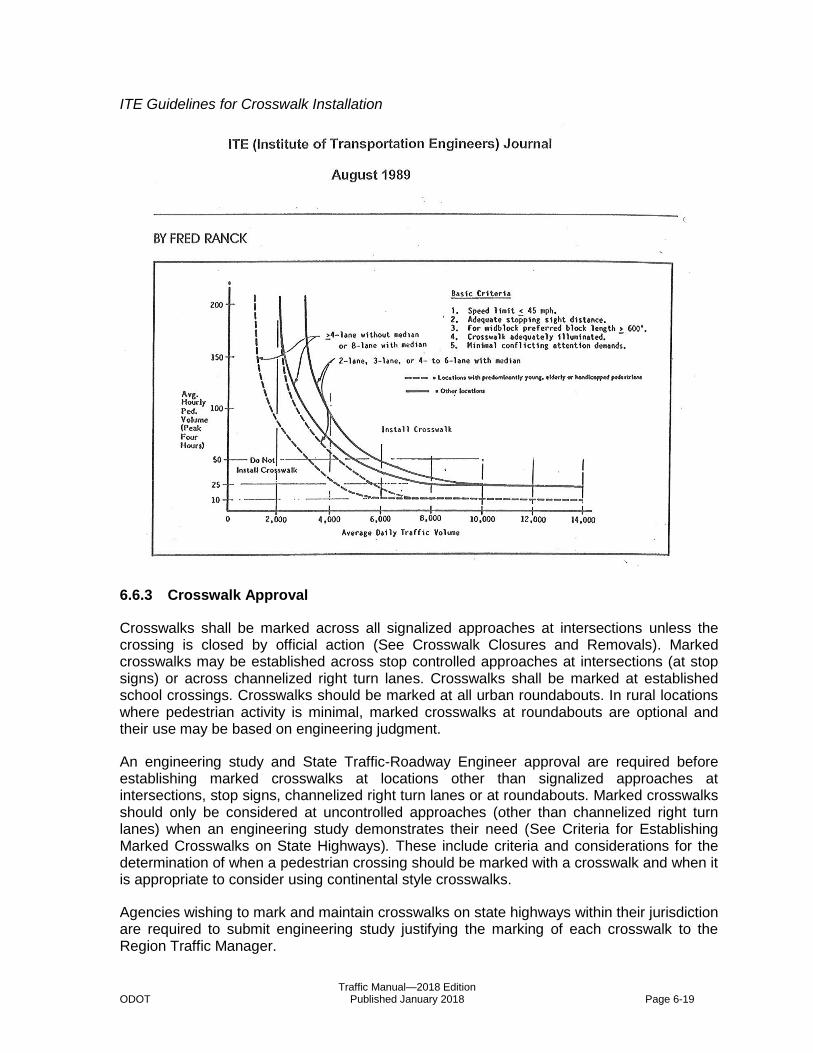
Traffic Manual—2018 Edition ODOT Published January 2018 Page 6-19
ITE Guidelines for Crosswalk Installation
6.6.3 Crosswalk Approval
Crosswalks shall be marked across all signalized approaches at intersections unless the crossing is closed by official action (See Crosswalk Closures and Removals). Marked crosswalks may be established across stop controlled approaches at intersections (at stop signs) or across channelized right turn lanes. Crosswalks shall be marked at established school crossings. Crosswalks should be marked at all urban roundabouts. In rural locations where pedestrian activity is minimal, marked crosswalks at roundabouts are optional and their use may be based on engineering judgment.
An engineering study and State Traffic-Roadway Engineer approval are required before establishing marked crosswalks at locations other than signalized approaches at intersections, stop signs, channelized right turn lanes or at roundabouts. Marked crosswalks should only be considered at uncontrolled approaches (other than channelized right turn lanes) when an engineering study demonstrates their need (See Criteria for Establishing Marked Crosswalks on State Highways). These include criteria and considerations for the determination of when a pedestrian crossing should be marked with a crosswalk and when it is appropriate to consider using continental style crosswalks.
Agencies wishing to mark and maintain crosswalks on state highways within their jurisdiction are required to submit engineering study justifying the marking of each crosswalk to the Region Traffic Manager.
Traffic Manual—2018 Edition ODOT Published January 2018 Page 6-20
6.6.4 Crosswalk Closures and Removals
By statute (ORS 801.220) crosswalks exist at all locations where crosswalk markings indicate a pedestrian crossing and at all intersections (whether marked or unmarked) unless closed by official action. The absence of marked crosswalk lines at an intersection does not preclude ADA requirements for providing ADA accommodation such as adding or upgrading existing curb ramps to meet current ADA standards for all quadrants of an intersection unless a crosswalk has been closed by official action.
6.6.4.1 Engineering Study
Removing or closing any crosswalk on the State Highway System requires approval of the State Traffic-Roadway Engineer. If a crosswalk is closed appropriate signing shall be installed in accordance with this manual and the ODOT Highway Design Manual. All requests for crosswalk closures or removals shall be submitted to the State Traffic-Roadway Engineer with an engineering study substantiating a geometric design or operational concern that adversely impacts pedestrian safety. The cost of meeting ADA requirements is not a factor to be considered in whether a crosswalk is to be closed or removed. Any crosswalk closure request shall document an alternate ADA accessible path between the two points of the crossing that are being closed demonstrating that the closure will not adversely impact accessibility (e.g. A sidewalk with a utility pole in the middle of the sidewalk between 2 curb ramps may necessitate relocation of the utility pole in addition to curb ramps being upgraded to complete the accessible alternate route.)
The following conditions are examples of when closing a crosswalk is recommended:
When a crosswalk improvement project proposes enhancements on only 1 leg of an intersection and due to safety concerns making it the preferred crossing location, closing the crosswalk on the opposite side of the intersection is recommended. The closed crosswalk would not require the installation of new ADA ramps or improvement of existing ADA ramps for the crosswalk that is being closed.
When physical restrictions on the opposite side of the roadway hinder pedestrian activity on that side of the roadway, closing the crosswalk is recommended. Typical examples of this condition include “T” intersections where directly behind the opposite side of the roadway is railroad right-of-way, a drainage canal, or some other type of waterway where pedestrian activity is discouraged and/or prohibited. An exception will be when there are transit connections on the opposite side of the roadway.
6.6.5 Crosswalk Safety
There is conflicting evidence as to the effectiveness of marked crosswalks on motorist behavior and pedestrian safety. ODOT has followed a practice of reluctance to mark crosswalks at locations other than controlled locations (i.e., signals and stop signs) and school crossings. Numerous studies (San Diego, 1972, Long Beach, 1986, Brigham Young, 1996, Santa Anna, 1999) have shown that marking crosswalks at uncontrolled locations can increase crash risk for pedestrians. In contrast some studies show higher rates of motor vehicle yielding to pedestrians at marked crosswalks.

Traffic Manual—2018 Edition ODOT Published January 2018 Page 6-21
Recent studies (Zegeer, 2000) suggest that wider (multi-lane) or higher volumes (above 10,000 ADT) contribute to higher crash risk for marked crosswalk vs. unmarked crosswalks. The study also found that the presence of a raised median was associated with a lower crash risk. Another study (Knoblauch, 1999) documented that pedestrians and motorists did not exhibit observable unsafe behaviors in marked crosswalks, in fact observable pedestrian behavior actually improved. The previous study commented that one possible explanation to higher crash rates in marked crosswalks is that a marked crosswalk may attract a higher percentage at-risk pedestrians, children and older adults (Zegeer, 2000).
From the pedestrian's point of view, a crosswalk is large and clearly marked. Crosswalks are far less visible to the drivers than to the pedestrians. At speeds greater than 45 mph, crosswalks are indiscernible at the distance a driver needs to begin braking to safely stop for pedestrians. It is important to ensure that the crosswalk markings and pedestrians are highly visible to motorists.
Marked crosswalks are routinely requested to increase the safety of crossing the highway. The function of the marked crosswalk is to provide guidance to the proper crossing location and to serve to alert motorists of a pedestrian crossing point. But unjustified or poorly located crosswalks may not increase safety. Marking crosswalks unnecessarily or in locations where there are few pedestrians may lead motorists to disrespect the marking.
A driver who passes over crosswalks marked at every intersection or a location that rarely has pedestrians may be conditioned to not expect pedestrians and thus loses respect for crosswalk marking. These crosswalks may increase the crash risk to pedestrians and motorists alike.
Most experts agree that on a busy highway, marking a crosswalk alone is rarely an effective safety measure and in some cases may actually increase the pedestrian’s crash risk. Other measures such as median refuge islands, curb extensions and illumination should be considered before a crosswalk is marked. Other improvements include improving sight distance, better access management to reduce conflicts with driveways, pedestrian signs, etc. Consideration should also be given to the overall environment in which the pedestrian crossing occurs, beyond the immediate vicinity of the proposed crosswalk, i.e. sign clutter and visual distractions. (See also Crossing Strategies)
File Code: TRA 07-11
6.6.6 Crossing Strategies
The need for convenient, practical and safe pedestrian crossings of highways is a high priority for virtually all cities. Dispersed land use and long distances between intersections make it impractical in most cases to provide grade separation (over/underpasses) or positive traffic controls (signals). Another common request is for marked crosswalks.
There are many reasons pedestrians have difficulty crossing a highway:
High traffic volumes
Lack of adequate gaps
High traffic speeds
Traffic Manual—2018 Edition ODOT Published January 2018 Page 6-22
Long crossing distances
Multiple travel lanes
Poor visibility
The first two obstacles (high traffic volumes and lack of adequate gaps) are difficult to resolve with a simple crossing strategy, but there are several ways to mitigate the other factors. The following measures should be instituted before a crosswalk is marked at a location other than a traffic signal:
6.6.6.1 Traffic Speeds
Most conventional “traffic-calming” methods are not appropriate on state highways, but there are measures a jurisdiction can undertake to alert drivers they are entering an area with expected pedestrian activity. These include, but are not limited to, sidewalks, street trees, median islands, bike lanes, visually narrowing the cross-section with better lane definition, bringing buildings closer to the back of sidewalks, maintaining on-street parking, etc.
6.6.6.2 Long Crossing Distances
Using good design practices, the roadway cross-section can be reduced by selectively narrowing or even eliminating unnecessary roadway elements (i.e. travel lanes, turning lanes, bike lanes or parking). Where on-street parking is present, curb extensions should be considered.
6.6.6.3 Multiple Travel Lanes
Assessing a safe and adequate gap in traffic becomes more difficult as the number of travel lanes increases. Islands can break up the crossing into discrete steps, so the pedestrian has to deal with fewer conflicts at a time. If the crossing point is at an intersection with a right-turn lane, an island between the right-turn lane and the through lanes enables the pedestrian to cross just the turning lane first. This breaks the crossing into more manageable parts.
The most important island to provide is in the median. This enables a pedestrian to cross traffic in one direction only, in two easy steps. It can be up to 5-7 times easier to cross a 4-lane road in two steps than all at once.
6.6.6.4 Poor Visibility
Pedestrians rarely knowingly step in front of moving traffic, and drivers don’t purposely hit a pedestrian they could see and react to in time. Measures to address visibility include removal or relocation of obstructions (signs, signal boxes, etc), curb extensions (where on-street parking is present) and illumination. Curb extensions allow pedestrians to better see on-coming traffic, and drivers to better see pedestrians about to cross. Approximately 60% of pedestrian crashes occur at night, which is out of proportion to exposure. Illumination should be provided at all designated crossing points.
Traffic Manual—2018 Edition ODOT Published January 2018 Page 6-23
Note: providing visibility should not be carried to extremes; for example, removing all on-street parking, trees and other vertical elements may have the negative effect of increasing travel speeds, which is potentially a greater hazard to safe crossing.
6.6.6.5 Total Crossing Strategy
Before a crosswalk is considered at a location other than a controlled location (i.e., signalized intersection), all the following issues should be addressed:
Speed- ODOT and the local jurisdiction should work at slowing traffic speeds in a realistic manner;
Crossing distance - Review roadway width and reduce cross-section where possible;
Multiple travel lanes - Provide median and/or channelization islands
Visibility - Remove sight obstruction, provide curb extensions (where possible) and provide illumination if warranted. Pedestrian crossing signs, or improved signs - larger size and/or better reflectivity – should be considered
Only after all of the above issues have been adequately addressed should a marked crosswalk be considered on a busy, multi-lane highway.
Other issues that might deserve special attention include:
Reducing conflicts by use of appropriate access management techniques;
Considering the special needs of vulnerable or at-risk pedestrians; and
Proper signing of pedestrian crossings.
In slower-speed, two-lane environments, it may be more acceptable to mark crosswalks without all of these elements in place, though visibility is always important. The needs of the aging pedestrian should be addressed as well including the increased time needed to cross similar roadway widths.
A recent research report jointly sponsored by TCRP and NCHRP (TCRP 112 and NCHRP 562 – Improving Pedestrian Safety at Unsignalized Crossings) summarizes engineering treatments to improve safety for pedestrian crossings at unsignalized intersections, in particular high speed high volume roadways served by public transportation. The research developed recommended guidelines for selecting pedestrian crossing treatments, summaries of pedestrian treatments (including many noted within this manual), and possible revisions to the MUTCD for pedestrian warrants.
6.6.7 Pedestrian Activated Warning Lights
6.6.7.1 Background
Recent research shows that Pedestrian Activated Warning Lights at crosswalks may be an effective method for alerting drivers to the presence of pedestrians entering or within the

Traffic Manual—2018 Edition ODOT Published January 2018 Page 6-24
crosswalk. The flashing lights can be activated by pushbutton or with passive detection. Once activated the lights flash at various rates or remain lit depending on the product characteristics. Examples of Pedestrian Activated Warning Lights at crosswalks include the following:
Warning Beacons as supplemental emphasis to the W11-2 Pedestrian sign;
Rectangular Rapid Flashing Beacons (RRFB);
In-Roadway Lights; and
Pedestrian Hybrid Beacons.
6.6.7.2 Investigation
Of particular interest is the effectiveness of the devices as safety improvements. There is a concern that the crossings, particularly where the pedestrian activates the warning lights by push button, could increase pedestrian assertiveness and potentially be dangerous. Also of concern are the potential maintenance costs (some systems have had reports of poor reliability and problems with the equipment), potential liability, effectiveness of driver compliance, and their effectiveness over longer periods of time.
Due to these concerns it is important that these devices be used where they are most likely to be effective and where disadvantages are minimized. They should only be considered after other more traditional safety measures such as pedestrian refuge islands or curb bulb-outs have been proven ineffective.
While these devices appear to improve pedestrian mobility, they do come at a cost. Estimates vary depending on the width of the roadway and type of device used, ranging from $10,000 for low-end treatments to more than $100,000 per location for a Pedestrian Hybrid Beacon. Passive detection systems cost even more. Logically their use should be limited given their initial cost and unknown safety and maintenance record. CalTrans has adopted a policy that a city may install these devices on state highways if they agree to assume all costs associated with their installation and operation. Similarly, ODOT may choose to install these devices if the local jurisdiction agrees to pay for all installation, operations, and maintenance costs.
6.6.7.3 Guidelines for Approval
ODOT has received several requests to install Pedestrian Activated Warning Lights at crosswalks on State Highways. Until such time as more experience is developed with these devices and because of limited funding ODOT should continue to support the installation of proven techniques for pedestrian safety prior to the installation of these devices. The use of these devices should be limited to areas where proven pedestrian safety measures have been installed and additional pedestrian warning is desired. The Traffic-Roadway Section should be notified early in the project development process if Pedestrian Activated Warning Lights are being considered at an existing crosswalk on State Highways. Such systems also require an operational approval letter from the State Traffic-Roadway Engineer prior to final plan development to ensure that all electrical systems (i.e. detection, push buttons, wiring) meet current Department standards. If the proposed location for Pedestrian Activated Warning Lights is at a new crosswalk on State Highways then prior approval from the State
Traffic Manual—2018 Edition ODOT Published January 2018 Page 6-25
Traffic-Roadway Engineer in accordance with the Delegated Authorities of the State Traffic-Roadway Engineer is required before design work can begin. Below are several Considerations for installation of these devices on State Highways.
6.6.7.4 Considerations
The Department has developed a list of Considerations that should be addressed in an engineering investigation that is submitted to the State Traffic-Roadway Engineer for locations where Pedestrian Activated Warning Lights are being considered. These Considerations should not be interpreted as warrants for Pedestrian Activated Warning Lights nor pass/fail criteria for the installation of a Pedestrian Activated Warning Lights. Rather they have been identified as important Considerations to take into account when proposing Pedestrian Activated Warning Lights at crosswalks on State Highways.
Engineering Considerations
Pedestrian Activated Warning Lights typically work best at locations where special emphasis is required such as mid-block crossings, crossings with a high percentage of vulnerable pedestrians (predominately young, elderly or disabled), or a history of pedestrian crashes.
Proven pedestrian safety measures such as median refuge islands and/or curb bulb-outs should be (or will be) in place prior to the installation of Pedestrian Activated Warning Lights.
The crosswalk crosses a multi-lane roadway (more than one lane in each direction) with more than 8,000 Average Daily Traffic (ADT) volume, 6,000 ADT if high percentage of vulnerable pedestrians.
The crosswalk is not controlled by traffic signal, stop sign or yield sign. There should be no other crosswalks, traffic signals or stop signs within 250 feet of the crosswalk.
Posted speeds should be 35 mph or less, but may not exceed 45 mph.
The crosswalk has an average of 25 pedestrians per hour (10 pedestrians per hour with high percentages of vulnerable pedestrians) for any four hours of the day. The crosswalk has nighttime pedestrian activity (at least half the volumes above for any two hours during the nighttime).
Local Support
The installation of Pedestrian Activated Warning Lights has public support.
Local jurisdictions agree to pay for installation, power and maintenance.
There is local commitment to education of the driver and pedestrian on the meaning and use of the devices.
Traffic Manual—2018 Edition ODOT Published January 2018 Page 6-26
Considerations
Consideration should be given to installing a Pedestrian Hybrid Beacon if the location meets an applicable traffic signal warrant.
It is recommended that drivers have sufficient decision sight distance to the Pedestrian Activated Warning Lights to be able to respond and stop for pedestrians if required.
Either automatic (passive detection) or push-button activation is allowed. If push-button activated the proper signing should be attached next to the push-button, such as the “PUSH BUTTON TO TURN ON WARNING LIGHTS” R10-25 sign in the 2009 Edition of the Manual on Uniform Traffic Control Devices.
6.6.7.5 Types of Pedestrian Activated Warning Lights
Warning Beacons as supplemental emphasis to the W11-2 Pedestrian sign
The installation of a standard Warning Beacon as a supplement to the standard W11-2 Pedestrian sign has historically been the most common type of pedestrian activated device used at marked crosswalks. Part 4 of the Manual on Uniform Traffic Control Devices contains typical applications of Warning Beacons and the Standards, Guidance, and Options that apply to such installations.
Rectangular Rapid Flashing Beacons (RRFB)
The Federal Highway Administration (FHWA) terminated Interim Approval for the optional use of Rectangular Rapid Flashing Beacons (RRFB) on December 21, 2017. RRFBs installed and turned on as of December 21, 2017 may remain in service until the end of useful life of that device. See Technical Services Directive TSB18-01(D) for more information.
In-Roadway Lights
Part 4 of the Manual on Uniform Traffic Control Devices specifies flashing rates, color of the warning lights, placement criteria and the Standards, Guidance, and Options that apply to such installations.
The usefulness of these lights is limited during daylight hours; they are difficult to see under normal daylight conditions. These devices tend to have a more significant effect during hours of darkness, rain or fog. Currently there is no confirmation that these devices reduce crash risk to pedestrians, but there is some supporting evidence that they increase driver’s awareness of pedestrians. Because of their relatively high installation costs, potentially high maintenance costs and their unproven safety record during key periods of pedestrian use, their installation should be limited to locations where they are justified.
There is some evidence (Whitlock & Weinberger Transportation, Inc., An Evaluation of a Crosswalk Warning System utilizing in-pavement Flashing Lights, April, 1998) that the in-roadway lights increase the percentage of drivers yielding to pedestrians; at least on a short term basis. However, research clearly documenting the safety benefits (i.e., percent reduction of pedestrian crashes) of in-roadway flashing lights, particularly on a long-term basis, is not available. ITE has prepared an informational report that contains information

Traffic Manual—2018 Edition ODOT Published January 2018 Page 6-27
and data on the in-roadway flashing light systems. The report gives a history of the system and a description of lighting devices and installation, as well as activation methods.
Other proven pedestrian safety measures (i.e., overhead illumination or median pedestrian refuges) should be employed and monitored for effectiveness before in-roadway lights are considered. Although these other methods can be as much or more expensive than the in-roadway lights their benefits are proven any time of the day, they require little or no maintenance and they have benefits to the motor vehicles as well as pedestrians.
Additional considerations for In-Roadway Lights
Overhead illumination for pedestrians is a proven safety measure for nighttime pedestrian activity. Good overhead lighting will allow the pedestrian to be more visible and may help wash out the glow of the in-roadway lights so they do not distract the pedestrian.
Applicable crossing signs need to be installed adjacent to the crossing location and will be supplemented with flashing beacons that are activated along with the in-roadway lights. Advance crossing signs may be used and may be supplemented with flashing beacons particularly when sight distance to the crosswalk is limited.
School crossings are not the best location for in-roadway lights. Most activity in school crossings should be during daylight hours. Overhead illumination and/or crossing guards may be better options.
Downtown areas may not be the best location for in-roadway lights. The addition of flashing lights in an already cluttered and distracting environment may do little to enhance pedestrian safety.
On roadways with bike lanes the outer lights should be placed to avoid the path of bicyclists.
Pedestrian Hybrid Beacon
The Pedestrian Hybrid Beacon is a new type of traffic control device introduced in the 2009 Edition of the Manual on Uniform Traffic Control Devices. The Pedestrian Hybrid Beacon has Standards and Guidance for installation found in the 2009 Edition of the Manual on Uniform Traffic Control Devices. All proposed installations of a Pedestrian Hybrid Beacon on the State Highway System must follow the criteria listed below.
A Traffic Signal Request Form shall be submitted by the Region Traffic Unit to the State Traffic-Roadway Engineer.
An engineering investigation shall be submitted to the State Traffic-Roadway Engineer showing that other alternatives for Pedestrian Activated Warning Lights as described in Section 6.6.7 have been considered and evaluated in comparison to the Pedestrian Hybrid Beacon.
Traffic Manual—2018 Edition ODOT Published January 2018 Page 6-28
6.6.8 Textured/Colored Crosswalks
6.6.8.1 Overview
The Traffic-Roadway Section issued a technical bulletin in December 2006 to provide direction to project delivery teams and District Managers relating to textured and colored crosswalks on state highways as part of Statewide Transportation Improvement Program (STIP) and Oregon Transportation Investment Act (OTIA) projects and each District’s pavement marking maintenance program.
6.6.8.2 Definitions of key terms
Textured Crosswalk: A surface material at a crosswalk such as brick, concrete pavers, or stamped asphalt, which is installed to produce small, constant changes in vertical alignment and to aesthetically enhance the crosswalk.
Colored Crosswalk: A pavement marking or proprietary product at a crosswalk, which is installed to contrast with adjoining paved areas and to aesthetically enhance the crosswalk.
6.6.8.3 Policy
ODOT practice is to not install textured or colored crosswalks. It is sometimes, however, a wish of a local road authority to install them. The perception is often times that the textured or colored crosswalk alone will be more visible than standard crosswalk marking. But often times that is not the case, textured or colored crosswalks can actually be LESS visible than conventional marked crosswalks (red brick tends to fade to black, especially at times of low visibility).
Textured crosswalks can be rough, impeding the movement of pedestrians with wheelchairs and walkers. They can become uneven, presenting a tripping hazard to pedestrians, especially the sight impaired. Textured or colored crosswalks are typically higher maintenance and some materials can become slick creating a slipping hazard. Installation costs are also high in comparison to conventional marked crosswalks.
6.6.8.4 Background
The Oregon Transportation Commission, through ODOT’s Chief Engineer has delegated the State Traffic-Roadway Engineer with the authority to designate pedestrian crossings on state highways. The Traffic Operations Leadership Team (TOLT) has become concerned that project teams have been specifying textured and colored crosswalks in STIP and OTIA projects without a proper engineering review by the Region Traffic Engineer and approval from the State Traffic-Roadway Engineer. Additionally, some project teams have used safety funds to pay for these aesthetic enhancements. Textured or colored crosswalk enhancements have not been documented to improve safety at crossings. Such use of safety funds to pay for textured and colored crosswalks is inappropriate and reduces the availability of these funds to pay for other proven pedestrian safety countermeasures such as curb extensions, raised median islands, illumination, and proper signing. The ODOT Traffic Manual provides clear guidance on textured and colored crosswalks on state highways. An Intergovernmental Agreement (IGA) with the local jurisdiction is necessary to ensure these enhancements are installed and maintained correctly. The IGA should be established with the local jurisdiction prior to letting any contracts for work involving the

Traffic Manual—2018 Edition ODOT Published January 2018 Page 6-29
installation or maintenance of textured/colored crosswalks. Where textured/colored crosswalks have been installed without such an IGA, ODOT should negotiate either (1) entering into an IGA with the local jurisdiction to cover ongoing maintenance and replacement costs OR (2) removal.
6.6.8.5 Action Required
Project delivery teams shall coordinate an engineering review with the Region Traffic Engineer for all proposed textured and colored crosswalks. The review shall document the proposed coloring, materials, pattern, funding source, installation, and maintenance requirements including consistency with the guidelines set forth in the ODOT Traffic Manual. Safety funds should not be used for coloring or pavement texturing of crosswalks. Any previously unapproved textured or colored crosswalks to be included in the project shall be submitted by the Region Traffic Engineer to the State Traffic-Roadway Engineer for consideration of approval.
District Managers or Striping Supervisors should, whenever possible, identify existing textured and colored crosswalks in advance of re-striping activities and coordinate with either the Region Traffic Office or the Traffic-Roadway Section to assess whether the crosswalks have been approved and who has the responsibility for maintenance. This will become easier as we continue to build our database of pavement marking information.
6.6.8.6 Implementation
The implementation of this policy will be monitored by Traffic-Roadway staff, the TOLT, and the Maintenance Leadership Team (MLT). Any revisions will be based on feedback from the Region Technical Centers, the TOLT, the MLT, and District Managers.
6.6.8.7 Procedure
Agencies wishing to textured/color crosswalks on state highways within their jurisdiction are required to submit justification for crosswalk texturing or coloring to the Region Traffic Manager/Engineer for review. On the state highway system, approval of the State Traffic-Roadway Engineer is required. Ordinarily, a local jurisdiction agrees to enter into an Inter-Governmental Agreement with ODOT to assume responsibility for all costs associated with the crosswalks including maintenance. If textured or colored crosswalks are used, they should be made of durable materials, such as stamped concrete, with minimal beveling. The textured surface should be built to adequate strength, with a good base resulting in low maintenance.
Colored crosswalks should consist of white or gray coloring. Alternate colors such as blue, red (brick), or green may be used provided the coloring is muted. Yellow or fluorescent yellow green coloring shall not be used since these colors are reserved for transverse lines separating traffic.
All textured or colored crosswalks shall be supplemented with lateral white lines to increase their visibility to motorists. Texturing or coloring should not be used at locations where crossings are not established because they might indicate a crossing to pedestrians (i.e., mid-block between alleys).
Textured or colored crosswalk designs shall conform to the following:

Traffic Manual—2018 Edition ODOT Published January 2018 Page 6-30
Made of durable materials
Adequate strength with good base
Non-slip surface (even after wear)
Minimal beveling
6.7 Flashing Beacons
Flashing Beacons are described in Part 4 of the Manual on Uniform Traffic Control Devices. These standards should be consulted by anyone considering a request or need for a Flashing Beacons. All Flashing Beacons are supplemental to the appropriate warning or regulatory signing.
6.7.1 Intersection Control Beacon
ODOT takes a conservative approach to installing an Intersection Control Beacon at intersections with a history of crashes involving disregard of existing STOP or YIELD signs. A Warning Beacon installed as supplemental emphasis to an Intersection Warning or Stop Ahead sign may be more effective in warning traffic of an upcoming intersection than an Intersection Control Beacon. Also, a Stop Beacon installed above the STOP sign on a stop controlled side street approaching the state highway is an effective and less costly safety measure to install when compared to an Intersection Control Beacon.
Several research studies have tried to establish the effectiveness of an Intersection Control Beacon in reducing crashes at intersections. All such studies have been inconclusive. Some States have established policies for removing an Intersection Control Beacon at a two-way stop controlled intersection due to confusion for drivers approaching the intersection from the stop controlled side street. Drivers from the stop controlled side street can see that all approaches of traffic have an indication, but cannot see the color of the indications for the other approach directions. Therefore drivers from the stop controlled side street might assume that all approaches have red indications and must stop. Regardless, it does not appear the installation of an Intersection Control Beacon alone is an effective safety measure.
Installation of an Intersection Control Beacon should only be considered if safety improvements at an intersection still leave some doubt as to the visibility of the intersection or type of intersection control.
6.7.2 Warning Beacon
The installation or removal of a Warning Beacon as a supplemental emphasis to existing warning signs (except for Emergency Signal signs) does not require the approval of the State Traffic-Roadway Engineer. The installation or removal of a Warning Beacon as a supplement to Emergency Signal signs does require the approval of the State Traffic-Roadway Engineer. Consult Part 4 of the Manual on Uniform Traffic Control Devices for typical applications of Warning Beacons and the Standards, Guidance, and Options that apply to such installations.
Traffic Manual—2018 Edition ODOT Published January 2018 Page 6-31
6.7.3 Speed Limit Sign Beacon
ODOT has limited use of the Speed Limit Sign Beacon on state highways to only those conditions covered by School Speed Limit Assemblies in Part 7 of the Manual on Uniform Traffic Control Devices and in accordance with Oregon Revised Statute 811.111. Further guidance on the use of Speed Limit Sign Beacons is contained in the ODOT publication A Guide to School Area Safety. While use of a Speed Limit Sign Beacon to indicate children arriving at or leaving school does not require the approval of the State Traffic-Roadway Engineer, the use of a Speed Limit Sign Beacon may be required as a condition of the School Speed Zone by the State Traffic-Roadway Engineer.
6.7.4 Stop Beacon
Use of a Stop Beacon installed above the STOP sign on a stop controlled side street approaching the state highway can be an effective and less costly safety measure to install when compared to an Intersection Control Beacon. Consult Part 4 of the Manual on Uniform Traffic Control Devices for Standards associated with the installation of a Stop Beacon.
File Code: TRA 16-6-42
6.8 Freeway Median Crossovers
6.8.1 Overview
Freeway median crossovers may be constructed on freeways and fully access-controlled expressways so that maintenance, emergency and law enforcement vehicles can avoid traveling long distances to respond to incidents, perform enforcement activities, and maintain highway operations during adverse weather conditions. These crossovers help facilitate maintenance activities such as snow removal and they also provide access for law enforcement or emergency responders to quickly reach roadway incidents.
6.8.2 Considerations
Although freeway median crossovers can be beneficial to maintenance and emergency responders, there are several considerations that should be taken into account before a request is submitted to the State Traffic-Roadway Engineer:
Is there sufficient width on the inside shoulder and in the median to accommodate a crossover allowing authorized vehicles to exit or enter the traffic stream in a safe manner?
Is there adequate sight distance for authorized vehicles to enter the freeway from a stopped condition at the proposed location of the crossover?
Are other crossover opportunities located more than 3 miles in either direction from the proposed crossover location?
Is the proposed crossover located outside the influence area of a nearby entrance or exit ramp to mitigate concerns with merging and weaving maneuvers in the vicinity of the crossover?
Traffic Manual—2018 Edition ODOT Published January 2018 Page 6-32
Is the proposed crossover located more than ½ mile away from undercrossing or overcrossing structures that might obscure the sight distance approaching the crossover?
Has there been communication and coordination between ODOT, local law enforcement, Oregon State Police, and emergency responders on the proposed location of the crossover and the needs of authorized users of the crossover?
Many of the considerations listed above are covered in the Criteria for Approval of Freeway Median Crossovers found in OAR 734-020-0105. Coordination with Oregon State Police is a key consideration as there are limited crossover opportunities for OSP troopers to engage in enforcement activities or respond to freeway incidents in the opposite direction.
6.8.3 Criteria
Criteria for approval of freeway median crossovers, conditions under which crossovers may be utilized, and persons authorized to use crossovers are covered in OAR 734-020-0100 through 734-020-0115. The State Traffic-Roadway Engineer can approve freeway crossovers if the location meets all criteria and conditions listed in OAR 734-020-0105. All requests meeting the criteria should be forwarded to State Traffic-Roadway Engineer for review. However, if one or more of those criteria are not met, the ODOT Chief Engineer (also called the Technical Services Manager) with FHWA consultation, considering need and safety, may approve and order the construction and installation of a freeway median crossover following and based upon an engineering investigation. The Traffic-Roadway Section must review the Region’s recommendation and submit them to the Chief Engineer (Technical Services Manager) with FHWA consultation for approval. The AUTHORIZED VEHICLES ONLY (R5-11) sign should be used at median crossovers to direct motorists not to use the crossovers.
File Code: TRA 16-08-05
6.9 Highway Advisory Radio
The Federal Communications Commission (FCC) licenses state and local agencies and government-affiliated agencies, such as airport authorities, to use low-power roadside transmitters to provide motorists with up-to-the-minute travel information via their AM/FM radios. These systems, which the FCC calls Travelers Information Stations (TIS), can provide warnings, advisories, directions, or other non-commercial material of importance to motorists. These licenses are issued under and must be operated in compliance with federal rule 47 CFR Chapter I, Part 90.242.
TIS operated by ODOT are known as Highway Advisory Radio (HAR). ODOT utilizes HAR to supplement messages provided on standard highway signs or variable message signs. HAR are permanently installed at locations where communication with travelers may be critical and may be temporarily installed in some work zones to provide travelers with timely information about a construction or maintenance project. Advance signs are posted to inform motorists about the availability of a HAR.
Messages, which are usually less than a minute in length, are recorded for continuous repetition. The message length is adjusted to permit the driver to receive the message at least twice while passing through the station’s coverage zone.
Traffic Manual—2018 Edition ODOT Published January 2018 Page 6-33
For ODOT HAR, the ITS Unit works with the Wireless Group of the Maintenance and Operations Branch to obtain and maintain the required FCC licenses. A license is specific to a transmitter location and broadcast area for permanent HAR installations. For temporary HAR, an area license which allows use on any state highway or for a specific corridor is required. ODOT does not maintain any license for temporary HAR and any temporary installations must be planned well enough in advance to obtain the required FCC license.
For TIS operated by other state agencies and local agencies with an established FCC license, advance signs may be posted on a state highway with State Traffic-Roadway Engineer approval. Examples of TIS uses other than for state highway information include severe weather alerts, Port traffic instructions, event management and local road construction or other detours. These signs must be installed in accordance with the guidelines given in ODOT’s Sign Policy and Guidelines for the State Highway System for the State Highway System (Chapter 5-12).
6.9.1 Guidelines for the Operation of Highway Advisory Radio and Traveler's Advisory Radio on State Highways
The Guidelines for the Operation of Highway Advisory Radio and Traveler's Advisory Radio on State Highways provides all of the guidelines and requirements for installing and operating HAR stations on state highways. The latest version is available for download from the ODOT Traffic-Roadway Section internet site under the Publications link.
6.10 Highway Safety Engineering
6.10.1 All Roads Transportation Safety (ARTS) Program
The mission of the All Roads Transportation Safety (ARTS) Program at the Oregon Department of Transportation (ODOT) is to carry out highway safety improvement projects on all public roads to achieve a significant reduction in traffic fatalities and serious injuries. The ARTS web site documents program philosophy and the application process for all Highway Safety funding. For purposes of programming Highway Safety funds in the Statewide Transportation Improvement Program (STIP), all highway safety infrastructure improvement projects shall follow the ARTS guidelines regardless of funding type (federal or state).
6.10.1.1 Highway Safety Improvement Program (HSIP)
The federal Highway Safety Improvement Program (HSIP) funds that comprise a majority of the funding for ODOT Highway Safety Engineering projects originally came from the Safe, Accountable, Flexible, and Efficient Transportation Equity Act: A Legacy for Users (SAFETEA-LU) signed into law on August 10, 2005. HSIP funding was slightly increased under the subsequent federal transportation reauthorization bill known at the Moving Ahead for Progress in the 21st Century Act (MAP-21) that was signed into law on July 6, 2012. HSIP funding will continue in the recently signed Fixing America’s Surface Transportation (FAST) Act that replaced MAP-21 in 2016 and extends federal transportation funding through 2020.
HSIP funds are primarily intended for infrastructure safety improvements on state highways, county roads, and city streets. Non-infrastructure highway safety improvements such as education and enforcement programs are administered by the ODOT Transportation Safety

Traffic Manual—2018 Edition ODOT Published January 2018 Page 6-34
Division and are typically funded with separate funding from the National Highway Traffic Safety Administration (NHTSA), the Federal Highway Administration (FHWA), or state funds.
6.10.2 State Strategic Highway Safety Plan
The State Strategic Highway Safety Plan (SSHSP) is a federal requirement and was developed by ODOT to address engineering, management, operation, education, enforcement and emergency services elements of highway safety. The SSHSP identifies highway safety improvement opportunities by addressing engineering, management, operations, education, enforcement and emergency management in order to focus resources on areas of greatest need and coordinate with other highway safety programs. The SSHSP may identify programs of projects, strategies or other key factors to reduce or eliminate safety hazards. The priorities identified in the SSHSP should be used to address all Safety and HSIP projects.
In response to the SSHSP requirement, Oregon has adopted the Oregon Transportation Safety Action Plan (TSAP). The TSAP in conjunction with the safety projects included in the Statewide Transportation Improvement Program (STIP) comprise Oregon’s SSHSP.
6.10.3 Program Management
ODOT has placed the responsibilities of Highway Safety Program management with the Traffic-Roadway Section (TRS). ODOT Regions are responsible for fund management within their own Regions and gathering information in support of the annual reporting process required by federal HSIP funding.
6.10.4 Highway Safety Engineering Committee
The Highway Safety Engineering Committee (HSEC) is set up by the Highway Division of ODOT to guide and give direction for highway safety engineering needs within the Department. The HSEC is responsible for reviewing and making recommendations for strategies and/or projects to be included in the State Strategic Highway Safety Plan and the ODOT Highway Safety Program. The committee also makes recommendations on emphasis areas to fund, approves regional safety funding allocation strategies, provides oversight on discretionary highway safety funding, and approves enhancements to Safety Management System (SMS) tools such as SPIS, Oregon Adjustable Safety Index System (OASIS), Crash Summary Report (CSR), CRF, and B/C analysis tools.
6.10.5 Safety Priority Index System (SPIS)
6.10.5.1 Overview
The Safety Priority Index System (SPIS) is a method developed in 1986 by the Oregon Department of Transportation (ODOT) for identifying potential safety problems on state highways. The development of SPIS complied with the federal Highway Safety Improvement Program (HSIP) and the Federal Highway Administration (FHWA) accepted SPIS as fulfilling the requirements of the HSIP. When Oregon began developing its Safety Management System in response to the 1991 ISTEA, it identified SPIS as one of several essential building blocks. SPIS has been recognized as an effective problem identification tool for evaluating state highways for segments with higher crash histories.

Traffic Manual—2018 Edition ODOT Published January 2018 Page 6-35
Several modifications to SPIS were implemented following the study, “An Evaluation of the Safety Priority Index System (SPIS),” completed by Dr. Robert Layton of the Transportation Research Institute at Oregon State University. These modifications were implemented in the 1998 SPIS reports, and were “fine-tuned” in the 1999 SPIS reports. These adjustments to the calculations created a large difference in the number of sites located in 1998 in comparison to years past, making it appear that more sites exist. However, the new calculations and listings are more applicable to both urban and rural sites, and should allow a better understanding of the reported values.
6.10.5.2 SPIS Method
The SPIS is a method of identifying locations where safety money may be spent to the highest benefit. The SPIS score is based on three years of crash data and considers crash frequency, crash rate, and crash severity. A roadway segment becomes a SPIS site if a location has three or more crashes or one or more fatal crashes over the three-year period. The priority index has three parameters and associated Indicator Values (IV):
crash frequency indicator value (IVFreq) 25% of SPIS score
crash rate indicator value (IVRate) 25% of SPIS score
crash severity indicator value (IVSeverity) 50% of SPIS score
Crash frequency indicator value (IVFreq)
The crash frequency indicator value, IVFreq, is a value between 0 and 25 determined using a logarithmic distribution based on total crashes in a three-year period.
IVFreq = (LOG(Total Crashes+1)/LOG(150+1))*25
The maximum indicator value of 25% is attained when the total number of crashes reaches 150 crashes on the same 0.10-mile segment over a 3-year period.
Crash rate indicator value (IVRate)
The crash rate indicator, IVRate, is a value between 0 and 25, also determined by using a logarithmic distribution based on the following crash rate calculations:
Crash Rate = (Total Crashes * 1,000,000)/(3 years * 365 * ADT)
IVRate = (LOG(Crash Rate+1)/LOG(7+1))*25
Again, the maximum indicator value of 25% is attained when the crash rate reaches seven crashes per million entering vehicles.
Crash severity indicator value (IVSeverity)
The crash severity indicator, IVSeverity, is a value between 0 and 50, which is determined by using a linear distribution from the calculation below:
IVSeverity = [((100 * (FATAL+INJA)) + (10 * (INJB + INJC)) + (1 * PDO)) * 300]/50
Where:

Traffic Manual—2018 Edition ODOT Published January 2018 Page 6-36
FATAL = the number of fatalities,
INJA = the number of severe injuries (Class A),
INJB = the number of moderate injuries (Class B),
INJC = the number of minor injuries (Class C),
PDO = the number of “property damage only” crashes.
The formula considers severity values between 0 and 300 only; therefore severity products above 300 are assigned the maximum value, to match the maximum indicator value of 50%.
The SPIS value is the sum of the above indicator values (IVFreq+IVRate+IVSeverity) for 0.10 mile (0.16 km) sections of urban and rural roads, shifted by 0.01 mile for each new section.
6.10.5.3 Reports
Each year, the Traffic-Roadway Section generates regional reports of the top 5, 10, and 15 percentile ranked SPIS sites for review by the five Region Traffic Units. The Region staff evaluates at a minimum the top 5% of sites on this report and considers the safety problems that may be contributing to the crash history at these locations. If a correctable problem is identified, benefit/cost analysis is performed on viable options and appropriate projects are initiated based on those with the highest benefit/cost. While the SPIS reports are computer-generated by the Traffic-Roadway Section, the rest of the process are manual site-specific evaluations and are primarily performed by Region Traffic Unit personnel.
Traffic-Roadway Section produces an annual report on the progress of the Highway Safety Improvement Program (HSIP) for FHWA each year by August 31. The report is produced evaluating the effectiveness of Highway Safety Engineering projects at reducing fatalities and injuries.
OASIS and CSR programs are created annually by the SPIS process for use by staff in evaluating sections of highway. The OASIS program was developed as an online safety analysis tool that is capable of performing “SPIS like” safety analysis and allows users to vary the SPIS calculations. The CSR program allows the user to enter a section of state highway, from milepost ‘x’ to milepost ‘y’. The database then yields information for that section of highway regarding number and type of crashes, highest and lowest SPIS values, and traffic volume information. Refer to these websites linked above or Contact the Highway Safety Engineering Coordinator for further information.
File Code: TRA 10-22-01
6.11 Historical Markers
The Historical Marker Program has been transferred to the Travel Information Council through an interagency agreement, along with other sign programs of motorist service
Traffic Manual—2018 Edition ODOT Published January 2018 Page 6-37
nature. The Oregon Historical Marker Committee oversees the program and meets on a quarterly basis. A staff member of the Traffic-Roadway Section serves on the committee.
File Code: PAR 07-03
6.12 Interchanges
6.12.1 Interchange Modification Request
Federal policy requires an Interchange Modification Request (IMR) to justify any new or revised access point on the Interstate System, regardless of funding source. The Federal Highway Administration (FHWA) has the authority to approve all new or revised access points to the Interstate System. Requests for new or revised access points on the Interstate System may be associated with planning work and typically requires Region Traffic and TPAU support which may ultimately result in an Interchange Modification Request. Region Traffic staff typically participates in the documentation of the policy points that must be addressed in all Interchange Modification Requests. Interchange Modification Request submittals are coordinated by and sent to FHWA through the Roadway Engineering Unit of the Traffic-Roadway Section. IMR procedures are outlined in the Highway Design Manual. An informational guide, “Interstate System Access Informational Guide, August 2010” is also available. Contact the Interchange Engineer for questions or clarification regarding ODOT IMRs.
6.13 Illumination
6.13.1 Overview
All illumination on State Highways (both temporary and permanent) shall follow policy set forth in the ODOT Lighting Policy and Guidelines. Additional guidance on illumination design is provided in the ODOT Traffic Lighting Design Manual. Both publications are available electronically from the ODOT Engineering web site.
6.13.2 Temporary Illumination
Determining the need for temporary illumination on construction projects is part of the illumination design process. The engineer-of-record submits requests to the Region Traffic Manager/Engineer on highway construction projects where illumination for temporary protection and direction of traffic is recommended. Staff from the Region Traffic Unit investigate and approve the amount of illumination needed based on ODOT Lighting Policy and Guidelines. Any deviation from statewide policies or standards must be reviewed by the Traffic-Roadway Section and submitted to the State Traffic-Roadway Engineer for approval.
A consistent and systematic approach is used which considers, at a minimum, the cost, safety (traffic, pedestrian and construction worker), traffic volume and speed, geometric conditions, crash history, weather, length of contract, and the amount and complexity of stage construction. Attention is given to installing proposed permanent lighting as soon in the construction project as practical so as to serve for temporary protection and direction of traffic purposes.
Traffic Manual—2018 Edition ODOT Published January 2018 Page 6-38
6.13.3 Permanent Illumination
Roadway lighting warrants are covered in the ODOT Lighting Policy and Guidelines. ODOT does not use specific illumination warrants to determine whether lighting is to be provided on a project.
An investigation is conducted and the agency utilizes engineering judgment of local conditions, considering such factors as availability of funds, traffic and crash data, roadway characteristics, etc., in determining when and where lighting is to be provided.
Lighting maintenance, energy and construction costs are evaluated when recommending illumination. Policy for illumination cost sharing with cities and counties on state highways is published in the 2002 Policy Statement for Cooperative Traffic Control Projects. Region Traffic Unit staff identify locations for illumination in the project development process for incorporation into the State Transportation Improvement Program (STIP).
The Safety Priority Index System (SPIS) and the crash database are used as tools to identify potential locations. The percentage of nighttime crashes and total crash history is considered in the benefits of installing illumination. Sometimes, improvements in traffic control devices, and/or geometric designs, will also serve to cut down on nighttime crashes and lighting may not be needed.
Illumination is reviewed by the Region Traffic Unit for policy agreement and statewide consistency before going to the engineer-of-record for incorporation into project plans. Any deviation from statewide policies or standards must be reviewed by the Traffic-Roadway Section and submitted to the State Traffic-Roadway Engineer for approval.
File Code: TRA 16-01
6.14 Intersections
Intersections are planned points of conflict on the state highway system. When the different crossing and entering movements by drivers, pedestrians, and bicyclists interact, it’s easy to see why an intersection is one of the most complex traffic situations that highway users encounter. Dangers are compounded when we add the element of highway users disregarding the traffic controls in place at a particular intersection. An investigation of safety and operations issues should be performed for every proposed new approach to the state highway system and for existing approaches where a change in the type of traffic control for a particular intersection is being considered as part of State Transportation Improvement Program (STIP) project or operational improvement to the intersection.
One of the common mistakes made in scoping intersection safety and operational improvements is deciding on a solution before a thorough alternatives analysis has been completed. The potential improvements to safety and operations need to be weighed not only against the construction costs but also the ongoing operations and maintenance costs for the expected life of the improvement through a benefit/cost (B/C) analysis. Potential intersection projects being considered for inclusion in the STIP should be identified as an “intersection improvement” project rather than a roundabout, traffic signal, or other type of traffic control until such time that an Intersection Traffic Control Study has been conducted and consensus has been reached on the proper traffic control solution for the intersection.
Traffic Manual—2018 Edition ODOT Published January 2018 Page 6-39
Since vehicular delay and the frequency of some types of crashes are sometimes greater under traffic signal control than under STOP or YIELD control, alternatives to traffic signals should be considered even if one or more of the warrants and other minimum conditions are satisfied. See Part 4 of the Manual on Uniform Traffic Control Devices for a list of possible alternatives. The range of alternatives should address the primary justification for consideration of a traffic signal. The Traffic Manual contains information related to several of common alternatives to traffic signals including:
Roundabouts;
Traffic Signals; and
STOP Sign Applications.
Traffic Manual users should refer to these sections for detailed information on ODOT practices for that specific type of intersection traffic control keeping in mind that several alternatives should be considered before deciding on a final solution.
6.14.1 Intersection Traffic Control Study
An Intersection Traffic Control Study should be completed when significant changes to an intersection are under consideration. The purpose of the study is to determine the most appropriate form of traffic control at an intersection given the benefits of each alternative and the right-of-way, environmental, cost, and other constraints. Region Traffic staff or the applicant requesting the traffic control device may complete the engineering study. If the Region Traffic Engineer/Manager concurs with the study, the Region Traffic Engineer/Manager documents concurrence and submits a request for State Traffic-Roadway Engineer approval with a detailed cover letter.
The following does not represent an exhaustive list of considerations but contains the essential elements that should be included in the study.
6.14.1.1 Diagram of Existing Intersection and Traffic Volumes
Using a diagram of the intersection as it currently exists, provide vehicular and pedestrian volumes for the intersection for which the traffic signal is being requested and intersections in the surrounding area. Peak AM and PM traffic volumes, based on 16-hour count data should be provided. Describe the traffic that is actually present or certain to be present when the traffic signal is operational. Estimate future traffic for at least a 20-year period.
6.14.1.2 Signal Warrants Analysis
If a traffic signal is being included as an alternative, include the results of a traffic signal warrants analysis (for warrants see Part 4 in the Manual on Uniform Traffic Control Devices). Satisfaction of each Manual on Uniform Traffic Control Devices warrant should be evaluated. Warrants 1-8 should be evaluated for existing conditions and traffic that is actually present or certain to be present when the traffic signal is operational. Satisfaction of Warrant 7, Crash Experience, should be based on the three most recent calendar years for which crash data is available. Only those crash types susceptible to correction by traffic signal control should be considered. The Traffic Signal Warrant Analysis form should be utilized.
Traffic Manual—2018 Edition ODOT Published January 2018 Page 6-40
When a traffic signal is part of a roadway improvement project, the request should be based on projected volumes developed according to the methodology in the Analysis Procedures Manual. The Preliminary Traffic Signal Warrant Analysis form should be utilized. The analysis should demonstrate that Warrant 1 would be met within three years after construction.
According to the Manual on Uniform Traffic Control Devices, the traffic signal warrants are minimum conditions under which installing traffic signals might be justified. A traffic control signal should not be installed unless the Traffic Signal Engineering Investigation indicates that installing a traffic signal will improve the overall safety and/or operation of the intersection.
See the Traffic Signal Policy and Guidelines for a description of Manual on Uniform Traffic Control Devices warrants and additional considerations that may support installation of a traffic signal for special applications.
6.14.1.3 Conceptual Design
Include diagrams or plans of the layout of the traffic control alternatives under consideration. Include the following:
For traffic signal alternatives, proposed lane usage and signal phasing based on analysis of current and projected volumes, traffic patterns, and safety and operational considerations. Refer to the ODOT Traffic Signal Policy and Guidelines.
Current and expected posted speed after construction.
Sight distances.
Bicycle and pedestrian facilities.
Conflicting accesses to be moved or closed.
Current and proposed land uses of the area.
Railroad or light rail within 500 feet.
6.14.1.4 Safety Analysis
Identify any safety concerns and explain how they will be resolved, e.g., sight distances, alignment, prevailing speeds (design speed for new construction or posted speed if on system), crash histories, railroad crossings, nearby access movements, etc. Include a qualitative or quantitative assessment of each alternative’s anticipated safety performance.
6.14.1.5 Operational Analysis
Conduct a capacity analysis, queuing analysis, and other types of operational analysis as appropriate for each traffic control alternative. See the ODOT Analysis Procedures Manual for methodology. Consider the ability to accommodate a variety of users from transit buses, bicycles, pedestrians, and trucks.
Traffic Manual—2018 Edition ODOT Published January 2018 Page 6-41
If the intersection is within 500 feet of a highway-rail grade crossing, provide information on the impacts of the intersection operations at the crossing. This should include a traffic impact analysis of present and future traffic queues affecting the crossing. Current requirements for crossing safety improvements can be obtained from the Rail & Public Transit Division, Crossing Safety Section. The Rail & Public Transit Division should be contacted early in project development.
If the proposed location is within ½ mile of an existing or possible future traffic signal include a traffic signal progression analysis as described in OAR 734-020-0480.
Elements of a traffic signal progression analysis include the following for each requested time period:
A diagram showing the volumes used at each intersection with the year of the projection and the hour covered
A time space diagram labeled with the cycle length, the distance between traffic signals, the year of projected volumes, and the hour covered. The diagram should show the green bands for the highway and the progression speeds.
Supporting documentation showing the green splits and v/c ratio for each of the movements at each of the traffic signals in the system. The inputs such as saturation rate, heavy vehicles, etc. should also be available. This information should be labeled to correspond with the correct time space diagram.
A statement of the results of the study.
6.14.1.6 Transportation Plan Consistency
Provide information from pertinent transportation plans (local, regional, and state) to demonstrate consistency between the plan and the proposed intersection improvements. Explain discrepancies between the plans and the proposed improvements.
6.14.1.7 Other Agency Support
Provide evidence of support of other agencies for the proposed improvements. Provide a description of the proposed funding and maintenance agreements. Include a description of the public input process and any key correspondence with local jurisdiction representatives.
6.14.1.8 Justification
The study should contain a clear and supported statement of the need for the selected traffic control device. Primary considerations used to select the recommended form of traffic control should be explained.
6.14.1.9 Application for State Highway Approach
If the request is for a traffic control device at a location subject to Division 51 administrative rules relating to state highway access, include a copy of the Application for State Highway Approach, a statement regarding the status of the application, and a copy of the Traffic Impact Study, if one is required.

Traffic Manual—2018 Edition ODOT Published January 2018 Page 6-42
6.15 Land Use and Transportation
The Oregon Highway Plan encourages compact development in urban areas while supporting mobility on designated highways segments. Expressway classification supports mobility on designated highways and highway segments by providing for high speed and high volume traffic with minimal interruption. Special Transportation Areas (STA’s) promote community vitality and livability in downtown areas by encouraging compact development and reducing local trips on the state highway and encouraging more opportunity for walking, bicycling or transit use. Urban Business Areas (UBA’s) and Commercial Centers improve the connection between the use of the highway and commercial activity and are used in conjunction with STA’s and expressways to balance mobility and livability.
See the Oregon Highway Plan (OHP) on the ODOT Planning & Technical Guidance web site for copies of the OHP and the Implementation Handbook.
6.16 Lanes
6.16.1 Climbing and Passing Lanes
Passing lanes are distinguished from climbing lanes. Climbing lanes are generally used where grades cause unreasonable reductions in operating speeds of some vehicles. Passing lanes are typically used where there may be inadequate passing opportunities either because of sight distance limitation or as traffic volumes begin to approach capacity.
Passing lanes tend to reduce unsafe passing maneuvers and may aid in reduction of head-on and sideswipe crashes. The addition of a climbing or passing lane can break up the formation of queues for a limited distance. Typically, queues begin to re-form downstream from a climbing/passing lane within a distance of ½ to 1 mile (800 to 1600m). Note that passing and climbing lanes do not actually add capacity to a facility.
Slow vehicle turnouts are not considered adequate opportunities for passing, since they are ineffective without the cooperation of slower vehicles and are generally too short to completely break up an established queue. Current ODOT policy does not allow construction of new slow vehicle turnouts unless allowed by a Roadway Design Exception. These should only be considered when a passing lane is not feasible and not as an alternative to a passing lane.
The need for a passing or climbing lane may be identified at the District or Region level. Transportation Planning Analysis Unit should be contacted to help analyze when and where climbing or passing lanes may be needed. Region Traffic can assist by requesting or conducting spot speed checks, requesting crash data summaries, and documenting on-site observations.
Special consideration should be given for when No Passing Zones should be established in the single lane direction of 3-lane Climbing and Passing Lanes. Refer to the Traffic Line Manual for specific guidance on when No Passing Zones should be established on 3-lane sections of highway.
See the Highway Design Manual for more information on climbing or passing lanes. Climbing and passing lanes are not a delegated authority of the State Traffic-Roadway Engineer and do not require the State Traffic-Roadway Engineer’s approval.
Traffic Manual—2018 Edition ODOT Published January 2018 Page 6-43
6.16.2 Lane Reduction Transition
When reducing the number of lanes of traffic, the right lane is normally dropped. This practice should be followed whenever possible to match driver expectation and to avoid high speed traffic making a merge maneuver. Uniform signing and striping reduces driver confusion. In situations where terrain, roadway geometry, or other factors suggest otherwise, the left lane may be dropped. Sign and stripe lane reduction transitions following guidance provided in the Sign Policy and Guidelines for the State Highway System, Sign Design Manual, Traffic Line Manual, and Parts 2 and 3 of the Manual on Uniform Traffic Control Devices.
6.16.3 Right-Turn Acceleration Lanes
See 6.39.3
6.16.4 Turn Lanes
See 6.39
6.17 Legislature
The Traffic-Roadway Section serves as advisor on legislative bills relating to traffic engineering, roadway engineering, contracting, access management, and issues associated with the Oregon Vehicle Code. During each session of the Oregon Legislative Assembly, staff from the Traffic-Roadway Section are actively involved in reviewing and completing the analysis of such bills. This includes reviewing and tracking bills, identifying potential ODOT impact, preparing for the hearings and providing the fiscal impact and written testimony for each bill and/or amendments. Participants work through the Highway Division Coordinators and the ODOT Legislative Coordinators in presenting the Department’s position on numerous bills. Some of this work extends beyond the annual legislative sessions to include legislative reports and Oregon Administrative Rules that must be developed in response to bills passed during the previous legislative sessions. The Traffic-Roadway Section also initiates legislation to help introduce or clarify traffic issues covered in the Oregon Vehicle Code through legislative concepts developed by the Oregon Traffic Control Devices Committee (OTCDC).
File Code: LEG 05
6.18 Litigation
The State of Oregon is self-insured through the Risk Management Division of the Department of Administrative Services. If a claim for damages involving ODOT is filed against the State, Risk Management conducts an investigation to determine whether the claim should be approved or denied. In some instances, the Risk Management Specialist in charge of processing the claim will contact one of the Traffic-Roadway Section’s investigators to request a recommendation and/or documentation, or to clarify a policy. If documentation is required, the Risk Management Specialist coordinates with ODOT sections or other public agencies to produce copies of the necessary documents.
Traffic Manual—2018 Edition ODOT Published January 2018 Page 6-44
Similarly, the Traffic-Roadway Section sometimes acts as a liaison for the Oregon Department of Justice when a request is made for information and documents by an Assistant Attorney General who is defending ODOT in a lawsuit. In addition to collecting documents and other evidence, the Traffic-Roadway Section may coordinate the acquisition of expert witnesses for testimony at trial. On occasion, a Traffic-Roadway Section employee may be required to testify, if he or she possesses specialized knowledge in a relevant area. At the request of the Department of Justice attorney, the Traffic-Roadway Section may also produce courtroom displays using mounted photo enlargements, graphics or video presentations.
Claims and lawsuits may result from a crash or construction and maintenance activities. When there is damage to ODOT facilities, such as a bridge damaged in a crash, ODOT may pursue damages from the party determined to be at fault.
The Traffic-Roadway Section also assists in gathering the information to support ODOT in these claims. The most effective way to reduce ODOT liability in litigation is to conform as closely as possible to standards, policies, and good engineering in the course of design, construction, inspection and maintenance, and then to thoroughly document such conformance.
File Code: LEG 04
6.19 Manual on Uniform Traffic Control Devices
6.19.1 Overview
Traffic control devices installed on highways within the State of Oregon are required to conform to the Manual on Uniform Traffic Control Devices (MUTCD), published by the Federal Highway Administration (FHWA). The list of highways that are required to conform to the MUTCD includes all state highways and public roadways under the jurisdiction of cities and counties within the State of Oregon. This requirement is established by Oregon Revised Statute (ORS) (see ORS 810.200) and Oregon Administrative Rule (OAR) (see OAR 734-020-0005). To promote uniformity and understandability of traffic control devices, private property owners are also encouraged to conform to the MUTCD when installing devices on private property.
Devices installed or replaced after the publication date of this document shall conform to the MUTCD upon installation. Unless noted otherwise, existing devices that do not conform to the current MUTCD shall be replaced at the end of their useful life.
The intent of the MUTCD is to enhance road safety and operation by requiring uniform, understandable, and effective traffic control devices on Oregon highways.
6.19.2 Oregon Supplement to the MUTCD
Deviations to the MUTCD are published in the Oregon Supplement to the MUTCD and made for justifiable reasons such as instances where Oregon law deviates from the MUTCD. These deviations are adopted through the OAR process and by approval of the FHWA.

Traffic Manual—2018 Edition ODOT Published January 2018 Page 6-45
The document supplements the current edition of the MUTCD as adopted by Oregon in OAR 734-020-0005. Both the Oregon Supplement and the MUTCD need to be consulted when researching traffic control issues.
The Oregon Supplement conforms to the organization and section numbering of the MUTCD. The two documents interact as follows:
Unless otherwise noted, language in the Oregon Supplement is added to the end of the referenced MUTCD section.
In other cases, the MUTCD language is deleted and/or the Oregon Supplement language inserted as directed by the instructions in italics.
The MUTCD is available on the internet in electronic format. Printed copies of the MUTCD and cost information are available from the American Association of State Highway and Transportation Officials (AASHTO), the Institute of Transportation Engineers (ITE), and the American Traffic Safety Services Association (ATSSA).
Design details for signs and traffic signals are not included in the MUTCD. They are in the Sign Policy and Guidelines for the State Highway System, the Traffic Signal Policy and Guidelines, and the FHWA Standard Highway Signs manual.
6.19.3 Exceptions to the MUTCD
There are no exceptions to the MUTCD. A change may be requested and requires a request for a change (See 6.18.6).
6.19.4 Deviations to the MUTCD
See Oregon Supplement to the MUTCD
6.19.5 Requests to Experiment
Requests to experiment include consideration of testing or evaluating new traffic control devices (See Section 1A.10 in the MUTCD).
6.19.6 Revisions to the MUTCD (Changes)
Changes to the MUTCD are adopted as part of the national standard and are published by FHWA (See Section 1A.10 in the MUTCD for the process to request a change).
File Code: TRA 16-09-02 Supplements / TRA 16-09-05 MUTCD Revisions
6.20 Naming Highway Facilities
The following guidelines are taken directly from Transportation Commission – 05 policy for naming highway facilities and are to be case-by-case basis (adopted October 15, 1991 by the Oregon Transportation Commission):
1. The Oregon Transportation Commission generally will not name highway facilities after individuals.

Traffic Manual—2018 Edition ODOT Published January 2018 Page 6-46
2. The Oregon Transportation Commission may elect to suspend guideline 1 if a requester can show compliance with the following criteria:
a. Demonstrated statewide support for naming a facility.
b. The honored individual shall have made a lasting contribution, with a significant and historic impact on Oregon.
c. The honored individual shall have been deceased for at least one year.
d. The facility is long enough to merit a title, such as a bridge or tunnel more than one-half mile long, or a highway section with defined end-points which was completed as a whole.
3. The comments of the Oregon Geographic Names Board will be solicited prior to naming any highway facility. (Any federal recognition will be contingent upon their approval.)
File Code: PUB 17-01
6.21 New Products
Testing of many new products is performed in conjunction with the ODOT Construction Section, Federal Highway Administration, and/or manufacturers. Product testing and evaluation of traffic control devices and equipment is conducted by the Traffic Systems Services Unit, Traffic Standards and Asset Management Unit, and the Traffic Engineering Services Unit. Manufacturers and suppliers can contact the Traffic-Roadway Section for information related to the proper process to obtain product approvals.
All products which are approved for traffic signal construction are contained in the “Blue” and “Green” sheets. The “Blue” sheets contain field-qualified equipment and materials while the “Green” sheets list conditional qualified controller equipment.
New products are reviewed by the Traffic Standards and Asset Management Unit in cooperation with other units, added to the “Blue” or “Green” sheets with related special provisions are amended as necessary. The “Blue” and “Green” sheets for signal equipment are available from the Traffic Signal Engineer of the Traffic Standards and Asset Management Unit.
File Code: MAT 00-02 (Blue & Green Sheet Files) – Traffic Standards and Asset Management Unit
6.22 One-way Operation for Trucks and Buses
The State Traffic-Roadway Engineer, in consultation with the Region Manager and Motor Carrier Services Manager, has been delegated the authority to designate sections of highways that allow one-way operation by class or type of vehicle. A field investigation shall be made and a written report prepared for each section of highway on which one-way truck and/or bus operation may be required. See OAR 734-020-0125 and 734-020-0130 for further information and the required field data for the report.

Traffic Manual—2018 Edition ODOT Published January 2018 Page 6-47
6.23 Parking
6.23.1 On-Street Parking
See the Highway Design Manual for information regarding the appropriateness of on-street parking. Diagonal parking may be allowed in designated Special Transportation Areas (STA’s) when approved by the State Traffic-Roadway Engineer through the design exception process. See HDM for further criteria.
File Code: TRA 07-01 and TRA 07-01-05
6.23.2 Prohibitions and Restrictions
Parking control on highways is covered in ORS 810.160, ORS 810.200, ORS 811.550, OAR 734-020-0020, OAR 734-020-0080, OAR 734-020-0085, and OAR 734-020-0090. The Region Traffic Unit should maintain a database of Parking Prohibitions and Restrictions that have been ordered by the Region Traffic Engineer. The Traffic Engineering Services Unit provides a form for summarizing engineering investigation data. (See Parking Prohibition Request Form)
A request for a parking prohibition or restriction on a section of state highway may be made by a city or county through which the highway runs. That jurisdiction should request the appropriate ODOT Region office to conduct an investigation. As a minimum, the investigation should involve the following:
On-site observation of safety and traffic flow conditions, preferably at a time of day when vehicles are parked in the proposed prohibition or restriction zone.
Photographs of the area from different approaches to show conditions at the site, preferably at a time of day when vehicles are parked in the proposed prohibition or restriction zone.
Contact, when appropriate, with affected businesses, citizens, police agencies, and local government jurisdictions, to explain the proposed parking prohibition or restriction, and to solicit their input. This can usually be accomplished by a person-to-person conversation, but in some instances may require attending a meeting of the local government authorities or a public hearing.
Once the investigation is completed, the Region Traffic Engineer reviews the investigation and makes a decision to approve or deny the parking prohibition or restriction. The decision of the Region Traffic Engineer shall be forwarded to the Traffic-Roadway Section for filing by the State Traffic-Roadway Engineer. The following three items should be included in any documentation forwarded to the Traffic-Roadway Section:
Completed Parking Prohibition Request Form
Map or Sketch of the vicinity with the proposed locations clearly marked
Photographs taken for the investigation

Traffic Manual—2018 Edition ODOT Published January 2018 Page 6-48
Normally, one or more of the following justifications are necessary for approving a request to eliminate parking:
Safety — this usually, but not always, has to do with sight distance for vehicles entering from a side street or driveway.
Congestion — Vehicles parked in the area impede the flow of traffic.
Damage to the facility — an example might be if parked vehicles are causing the shoulder to slough off.
Frequent use of the facility for a purpose not intended — this could be any number of things (unauthorized vending, dumping of trash or sewage, etc.).
In addition to these justifications, limited parking restrictions are sometimes granted as a courtesy to municipalities who request them (time limit, height restriction not related to sight distance, loading zone, parking spaces reserved for persons with disabilities, etc.). These requests are evaluated on a case-by-case basis, and with the understanding that the city will be responsible for installation and maintenance of the signs, and for enforcing the restriction. Parking spaces reserved for persons with disabilities shall meet the minimum requirements found in Oregon Transportation Commission Standards for Accesible Parking Places.
When a Parking Prohibition or Restriction has been approved, the Region Manager will receive a memo with instructions to have the appropriate signs installed, and to notify the State Traffic-Roadway Engineer of the installation date. The Region Traffic Engineer will also send a letter to the Oregon State Police, notifying them of the prohibition or restriction.
File Code: TRA 16 Procedures (Hwy. No. & Milepoint Letters of Approval)
6.24 Pavement Markings
6.24.1 Overview
The State Traffic-Roadway Engineer has the responsibility to establish a uniform system of pavement markings. The State Traffic-Roadway Engineer approves the installation, modification, and removal of traffic control devices including striping, other markings and pavement markers on the state highway system.
The traveling public relies heavily on pavement markings for guidance, positioning and information. Uniform pavement markings make a safer road system. Road users can respond appropriately and quickly when what they see has a standard, known meaning. Good application and maintenance of pavement markings is therefore an essential component of safe and efficient highways.
6.24.1.1 Pavement Markings Standard Drawings
The standard layouts for striping and marking of new construction or overlay sections are contained in the ODOT Oregon Standard Drawings, Traffic Section. These drawings should be consulted for striping and marking of pavement (also refer to the Traffic Line Manual). The standard drawings are also the basis for the design of striping plans on construction
Traffic Manual—2018 Edition ODOT Published January 2018 Page 6-49
projects. See the Striping Design Guidelines and Traffic Line Manual available from the Traffic Standards and Asset Management Unit for assistance in developing striping plans.
6.24.1.2 Traffic Line Manual
The Traffic Line Manual contains the ODOT policy and guidelines for installation of pavement markings. If markings not conforming to this manual are necessary, they should be reviewed and approved by the Region Traffic Manager/Engineer or, when required, by the State Traffic-Roadway Engineer.
6.24.1.3 Pavement Marking Design Guidelines
These guidelines provide information to assist designers in the preparation of striping plans. The guidelines are based on the Oregon Standard Specifications for Construction and ODOT project delivery process.
6.24.1.4 Standards for Accessible Parking Spaces
In accordance with ORS 447.233, the Oregon Transportation Commission adopted Standards for Accessible Parking Spaces, which took effect on January 22, 1992.
All new construction is required to meet new minimum standards. The standards are in compliance with 28 CFR Part 36 published by the Department of Justice in the Federal Register.
File Code: TRA 16-02
6.24.2 Advance Stop Bars
6.24.2.1 Background
“Multiple threat” crashes are a leading cause of pedestrian fatalities. A multiple threat crash occurs on multi-lane roads when one driver stops to let a pedestrian cross, but so close to the crosswalk as to obscure visibility in the adjacent lane. The pedestrian starts to cross, unaware that traffic behind the stopped vehicle or in the adjacent lane may not see him or her. Drivers behind the stopped vehicle or in the adjacent lane may not see the pedestrian and can’t understand why the first vehicle stopped. If they change lanes or continue traveling in the adjacent lane at a high rate of speed, and the pedestrian doesn’t see the car, the result is often a fatal or severe injury crash.
Recent research indicates a dramatic drop in multiple threat crashes when drivers are asked to stop approximately 30 feet back from the crosswalk. At higher distances (40 and 50 feet) stopping compliance rates begin to drop off. At shorter distances (20 feet) compliance marginally improves, but 20 feet does not provide as much visibility as 30 feet. Vehicles traveling at a high rate of speed may not be able to stop in time, but 30 feet frees up the sight distance triangle enough so the crossing pedestrian can see if a vehicle is proceeding towards him or her without stopping or slowing down, giving the pedestrian time to take evasive action.
Traffic Manual—2018 Edition ODOT Published January 2018 Page 6-50
6.24.2.2 Guidance
Advance stop bars, combined with the Stop Here For Pedestrians sign (R1-5b or R1-5c), should be installed at marked crosswalks at uncontrolled locations on multi-lane highway locations, unless unique circumstances prevent their installation. If only one crosswalk is marked on a multi-lane highway at an uncontrolled intersection, then the advanced stop bar and sign on the far side of the intersection may be omitted.
Advance stop bars, (24-inch width), should be placed approximately 30 feet in advance of the marked crosswalk. They may be placed between 20 to 50 feet in advance if unique circumstances dictate a different location.
6.24.3 No Passing Zones
No-passing zones are established at vertical and horizontal curves and at other locations where passing is prohibited because of inadequate passing sight distance. No pass striping is warranted where the passing sight distance is less than the minimum necessary for safe passing at the 85 percentile speed, statutory speed, or posted speed.
The authority to establish no passing zones on Oregon highways is provided in Oregon law (ORS 810.120). Part 3 of the Manual on Uniform Traffic Control Devices describes the criteria for determining the passing sight distance and application of no-pass zones.
Often a request is made to extend no-pass striping to include intersections near the end of no-pass zones or to provide no-pass striping at intersections. Generally these requests are denied because it is unnecessary. Oregon law (ORS 811.305) states that it is unlawful to pass at any intersection. As statutory no-pass zones, these highway segments do not require no-pass markings. Additionally, Intersection Warning Signs (W2-1 through W2-8) found in the Manual on Uniform Traffic Control Devices provide adequate warning to drivers of upcoming intersections and serve as a deterrent to passing when installed in advance of intersections.
Before installing no-pass pavement markings in advance of intersections, other options for addressing passing at intersections should be explored first. Intersection Warning Signs including advance street name plaques should be considered if not currently installed in advance of the intersection. Other actions include making the intersection more visible from the highway by trimming back shrubbery or trees, making sure stop bars are clearly marked and placed so that vehicles can be seen before entering the highway, and making sure parking is not interfering with visibility of traffic or the cross-street. Considerations should include amounts of pedestrians in the vicinity, business activity or residences nearby. An important indicator is the crash history of the area. Consideration should also be given to the availability of passing opportunities near the area.
When intersections are located near the beginning or end of no-pass striping for horizontal or vertical curves it may be appropriate to extend the no-pass striping through the intersection. Rural intersections, on the other hand, typically have sufficient sight distance and the no-pass zones are ineffective at changing driver behavior. The installation of no-pass striping in these areas may contribute to unrealistic expectations on the part of motorists entering the highway or turning from the highway. However, a no-pass zone may be considered where there is a history of crashes related to passing through the intersection.

Traffic Manual—2018 Edition ODOT Published January 2018 Page 6-51
Special consideration should be given for when No Passing Zones should be established in the single lane direction of 3-lane Climbing and Passing Lanes. Refer to the Traffic Line Manual for specific guidance on when No Passing Zones should be established on 3-lane sections of highway.
See the Traffic Line Manual for details and layout of no pass zones.
6.24.4 Two-Way Left Turn Lane
See the Traffic Line Manual and the Manual on Uniform Traffic Control Devices for standards and guidelines on how to mark two-way left turn lanes.
6.24.5 Yield Control Markings
Pavement markings for yield control are used to distinguish the point behnd which vehicles are required to yield in compliance with a YIELD (R1-2) sign. See the Traffic Line Manual and the Manual on Uniform Traffic Control Devices for standards and guidelines on use of yield control markings.
6.24.5.1 Sign Guidelines
See YIELD Sign Applications
6.24.6 Colored Pavements
The Manual on Uniform Traffic Control Devices provides standards for the use of colored pavements in Part 3. All proposed colored pavement applications shall be reviewed by the Region Traffic Engineer/Manager and State Traffic-Roadway Engineer for consistency with the Manual on Uniform Traffic Control Devices.
6.24.6.1 Textured/Colored Crosswalks
See 6.6.8
6.24.7 Shared Lane Markings
Shared lane markings (also referred to as sharrows) inform motorists and bicyclists that the lane in which they are operating serves both modes. The markings assist bicyclists with lane positioning and remind motorists to expect bicyclists in the lane. The markings are generally used where the shared lane is too narrow for a motorist and a bicyclist to travel side by side within the same lane. Shared lane markings are an optional treatment on ODOT highways.
The Manual on Uniform Traffic Control Devices provides standards and guidance for the use of shared lane markings in Section 9C. The 2012 AASHTO Guide for the Development of Bicycle Facilities includes additional guidance including a list of typical applications or scenarios where shared lane markings may be beneficial. Applications of this device under Condition A or B below should be reviewed by the Region Traffic Engineer/Manager for consistency with the MUTCD. Applications of this device under Condition C require approval by the State Traffic-Roadway Engineer.

Traffic Manual—2018 Edition ODOT Published January 2018 Page 6-52
As with other traffic control devices, the benefits to the traveling public and the costs of installation and ongoing maintenance should be assessed prior to installation. When applied appropriately, shared lane markings are associated with the following benefits:
alert motorists of the potential presence of bicyclists
guide bicyclists to a safe position within the lane
alert motorists of the lateral position bicyclists are likely to occupy
encourage safer passing practices by motorists
reduce the incidence of wrong-way and sidewalk bicycling
supplement way finding along bicycle routes and bicycle boulevards
6.24.7.1 Condition A
Shared lane markings are most appropriate on roadways where the evaluation criteria in Table 1-1 in the Oregon Bicycle and Pedestrian Design Guide indicate decreased need for mode separation and where posted or operating speeds are 20-25 mph. In these scenarios and on steep downgrades, shared lanes with shared lane markings may be preferable to other facility types such as bike lanes. Shared lane markings are particularly appropriate on these types of roadways that also have on-street parking.
6.24.7.2 Condition B
Shared lane markings may also be appropriate on roadways with posted speeds of up to 30 mph and an 85th percentile operating speed up to 35 mph (if available) when the preferred facility type such as a bike lane or separated bikeway does not exist and there is not adequate pavement width to install one. Additional measures to inform motorists of the potential presence of bicyclists in the roadway should be considered.
6.24.7.3 Condition C
Shared lane markings may also be considered on roadways with posted speeds above 30 mph or an 85th percentile operating speed above 35 mph that have limited alternative routes high bicycle volumes such as narrow bridges, tunnels, and other locations where the narrow roadway width requires bicyclists to ride in the travel lane with motor vehicles. If used in these situations, shared lane markings must be used in conjunction with other traffic control devices that serve to warn drivers of the shared roadway condition. The bicycle warning sign (W11-1) with the SHARE THE ROAD supplemental plaque, the BICYCLES MAY USE FULL LANE sign (R4-11), or an actuated beacon system with sign OBW1-8 may be appropriate.
Shared lane markings should not be used as a substitute for bike lanes or separated bikeways when those facilities are a preferable and feasible solution. The application of shared lane markings to a roadway does not change the responsibilities of roadway users and it does not lessen any need for bike lanes or other separated bicycle facilities. Shared lane markings shall not be used in bike lanes or on travel lanes in the same direction as bike lanes. Shared lane markings should generally not be used on high speed roadways or in
Traffic Manual—2018 Edition ODOT Published January 2018 Page 6-53
areas with limited sight distance as the markings may suggest a false sense of safety to the bicyclists in these applications. Other warning devices that target the attention of motorists may be more appropriate for these locations.
Guidance for the placement of shared lane markings is available in Section 9C of the MUTCD. If used on a street with on-street parking, the centers of the markings should be a minimum of 11 feet from the face of curb; if used on a street without on-street parking, the marking should be a minimum of 4 feet from the face of curb. In many instances, the best location for the markings is in the middle of the travel lane for both suggested bicyclist positioning and reduced maintenance needs. The placement should encourage a bicyclist to fully occupy a narrow lane in those instances where a motor vehicle cannot safely pass a bicyclist without leaving the shared lane. The placement should not contradict the expectation created by ORS 814.430 that bicyclists are to ride as far to the right as “practicable”. The MUTCD recommends a maximum spacing of 250 feet between markings so that bicyclists can see the next marking from the previous one (FHWA; December 19, 2009 Federal Register, p. 66860). Longer spacings may be appropriate in some locations as justified and documented in the engineering study.
6.25 Railroad Crossings
6.25.1 Overview
Railroad crossings and traffic control devices used within the crossing area are under the jurisdiction of the ODOT Rail & Public Transit Division. A Railroad Crossing Order for each public road grade crossing, summarizes the obligations, including, but not necessarily limited to, design, cost, maintenance, signals, signs, and operational requirements for all involved parties. Additional information can be found in the Traffic Signal Approval Process and Preemption sections of this manual. Design and operation details are also found in the following publications:
Traffic Signal Design Manual
Traffic Signal Policy and Guidelines
6.25.2 Added Stop Lanes
The following is the procedure for the investigation of added stop lanes for at grade railroad crossings. The purpose is to determine the need for additional stopping lanes at railroad at-grade crossings of a state highway when such crossings become involved in a major reconstruction project.
An additional lane constitutes an alteration (OAR Ch.741) to the grade crossing, which requires ODOT Rail & Public Transit Division approval as included in a Crossing Order.
Step 1- The Project Leader determines that an at-grade railroad crossing will exist within the project limits and requests an investigation from Region Traffic Engineer.
Step 2 - The need for adding stopping lanes or justifying the omission of such lanes from the location project is determined by a Field Diagnostic Review through the ODOT Rail and Public Transit Division. If the existing facility has paved shoulders of adequate width to accommodate vehicles that must come to a stop at a rail crossing, added stopping lanes
Traffic Manual—2018 Edition ODOT Published January 2018 Page 6-54
may not be needed. The Field Diagnostic Review may perform a traffic engineering study considering at a minimum the following data: average daily traffic volumes, number of train movements, an estimate of the number of vehicles required to stop, a gap study, posted speed or 85 percent speed, physical characteristics, alignment, terrain, and sight distance. The Diagnostic Team prepares a report and makes a recommendation to Rail & Public Transit Division Manager for inclusion in Crossing Order if a stopping lane is required. If not required, all parties should be so informed.
Step 3 - The Rail & Public Transit Division Manager considers information submitted by the Region Traffic Engineer for the required crossing order. Rail & Public Transit Division must have ample opportunity to provide input and assure proper coordination with the affected railroad company, and forward copies of Crossing Order to all interested parties.
Step 4 - The Project Leader complies with the terms of the Crossing Order, contacts Region Traffic Engineer (if any questions arise), and proceeds to develop appropriate plans.
6.26 Road Closures
The temporary or conditional closure of highways is covered by OAR 734-020-0150. The Traffic-Roadway Section does not initiate closures, but may offer technical assistance. Highlights of the Administrative Rule include:
1. When weather conditions or road conditions constitute a danger of highway damage or a danger to the safety of the driving public, the Chief Engineer (Technical Services Manager), Region Manager, District Manager, or Assistant District Manager may prohibit the operation upon such highway or section of a highway of any or all vehicles, or any class or kind of vehicles.
2. The prohibition of vehicles may result in total closure or conditional closure of highways or highway sections. Conditional closures may, at the discretion of the Chief Engineer (Technical Services Manager), Region Manager, or District Manager, or Assistant District Manager, include but not be limited to prohibition of several identified classes or kinds of vehicles.
3. Closures or conditional closures should be accomplished by physically barricading or blocking the highway, with placement of appropriate warning signs or devices, and, where possible, signing indicating conditional closure with types of vehicles allowed or prohibited.
4. Road closures and conditional closures are to exist only on a temporary basis and should be removed as soon as road conditions or weather conditions permit, the hazard has been removed, and the danger to the highway or driving public no longer exists.
6.27 Roundabouts
6.27.1 Overview
Roundabouts have been proven as a viable and sustainable alternative to Traffic Signals at many intersections. Compared to other types of intersection traffic control, roundabouts have demonstrated significant safety improvements including:
Traffic Manual—2018 Edition ODOT Published January 2018 Page 6-55
Reductions in fatalities of more than 90%;
Reductions in injuries of 76%;
Reductions in all crashes of 35%; and
Increased pedestrian safety due to slower vehicle speeds.
Roundabouts also reduce congestion and delay. They can be efficient during both peak and non-peak hours. Other distinct advantages of roundabouts include the following:
Reduced pollution and fuel use through fewer stops and hard accelerations;
Significant life-cycle cost savings when compared to Traffic Signals due to no signal equipment installation, power, or maintenance costs; and
Supports urban and rural community values through quieter operation and by providing a traffic control solution that is both functional and aesthetically pleasing.
Source: Roundabouts: A Safer Choice (FHWA-SA-08-006)
The FHWA has published several useful guidance documents that can be found on their roundabout internet site. The second edition of the publication entitled Roundabouts: An Informational Guide was recently published as NCHRP Report 672 in 2010. For proposed roundabouts on state highways in Oregon, staff should familiarize themselves with NCHRP Report 672, the Highway Design Manual, and the Roundabout Selection Criteria and Approval Process.
Before proceeding to the Roundabout Selection Criteria and Approval Process, a thorough alternatives analysis should have been completed in the form of an Intersection Traffic Control Study showing that a roundabout was a viable alternative when compared to other types of intersection traffic control. If a roundabout project is being considered for inclusion in the STIP it should be identified as an “intersection improvement” project rather than a roundabout, traffic signal, or other type of traffic control until such time that the Intersection Traffic Control Study has been conducted and consensus has been reached on the proper traffic control solution for the intersection. Refer to the Intersection section of the Traffic Manual for more detail on how to conduct this type of analysis.
File Code: TRA 16-10 (Highway No. and Milepoint)
6.27.2 Roundabout Selection Criteria and Approval Process
The primary guidance document for roundabouts on state highways is Highway Division Directive DES 02 dated November 9, 2012. In accordance with the Highway Division Directive, the State Traffic-Roadway Engineer has been delegated the authority to approve the installation of roundabouts on State Highways once the expectations and processes outlined in the Highway Division Directive have been met. Requests for roundabout evaluation shall be made through the Region Traffic Engineer in collaboration with the Technical Services Roadway Manager. All roundabout requests shall be accompanied by an Engineering Investigation and address the Considerations as described in the subsections below.
Traffic Manual—2018 Edition ODOT Published January 2018 Page 6-56
6.27.2.1 Engineering Investigation
A comprehensive Intersection Traffic Control Study shall be prepared. Details of crash history, traffic volumes, analysis of roundabout operation, and other safety concerns should be included. The investigation should also include comparisons of alternative intersection control (i.e. stop controlled, signal control, etc.) taking into account the operational aspects, life-cycle costs, and other considerations.
Design Life
For normal STIP projects use a 20-year Design Life from the date of construction. For development review a minimum 10-year Design Life will be used.
The State Traffic-Roadway Engineer must approve exceptions to the minimum Design Life. Exceptions may be granted where analysis shows a single-lane roundabout meets most of the Design Life and only fails in the outer years at which time expanding the roundabout into a multi-lane roundabout may be desired.
Conceptual Design
A scale drawing showing the Conceptual Design of the proposed roundabout should be included to assure appropriate geometry and layout elements can be obtained. Horizontal and vertical geometry must be clearly identified. Surrounding topography and approximate R/W should also be included.
6.27.2.2 Considerations
The Department has developed a list of Considerations that should be addressed in the Engineering Investigation that is submitted for proposed roundabout locations, These Considerations should not be interpreted as roundabout warrants nor pass/fail criteria for installation of a roundabout. Rather, they have been identified as important Considerations to take into account when proposing roundabout intersections on state highways.
Freight mobility needs should be sufficiently defined and addressed prior to Conceptual Approval.
Non-motorized user mobility needs such as the ability for bicyclists and pedestrians to safely move through the roundabout intersection should be balanced with the mobility needs of other motorized vehicles. Bicyclists should be given the option to use either the circulatory roadway with other vehicles or the pedestrian crossings outside the circulatory roadway. Special design consideration should be given for the pedestrian crossings at the entrances and exits on all legs of the roundabout where vehicles are either decelerating to enter the roundabout or accelerating to exit the roundabout.
Roundabout design should consider the needs and desires of the local community including speed management and aesthetics.
Intersection safety performance should be a primary consideration when pursuing a roundabout for intersection control. Predicted reductions in fatal and serious injury crashes should be compared with other types of intersection control such as
Traffic Manual—2018 Edition ODOT Published January 2018 Page 6-57
traffic signals or other alternatives supported by crash modification factors (CMF) found in the AASHTO Highway Safety Manual.
Roundabout entrance geometry, circulating geometry, and exit geometry should be designed to allow the design vehicle to traverse the roundabout in a reasonable and expected manner commensurate with best design practices as shown in NCHRP Report 672 and the Highway Design Manual. This design should utilize a representative template of the design vehicle and the vehicle path should be demonstrated through the use of computer generated path simulation software.
Roundabouts should meet acceptable v/c ratios for the appropriate Design Life. (See the Design Life subsection for possible exceptions to this consideration.)
Roundabouts proposed for state highways with posted speeds higher than 35 mph will require special design considerations (e.g. longer splitter islands, landscaping, reversing curves approaching the roundabout) to transition the roadside environment from higher to lower speeds approaching the roundabout intersection.
For Roundabouts with more than 4 approach legs, special design considerations should be made for the layout of the approach legs.
Roundabout proposals should address how roundabout operations would impact the corridor immediately upstream and downstream from the roundabout intersection. (If the proposed roundabout is in a location where exiting vehicles would be interrupted by queues from signals, railroads, drawbridges, ramp meters, or by operational problems created by left turns, accesses, these problems should be addressed by the Engineering Investigation.
6.27.2.3 Process and Approval
Once the State Traffic-Roadway Engineer receives a request, Traffic-Roadway Section staff will coordinate review with other Technical Services staff and will make a recommendation to the State Traffic-Roadway Engineer. If the information provided is insufficient or not appropriate methodology (as determined by the Department) the State Traffic-Roadway Engineer may request further analysis.
The approval process for Roundabouts is divided into two phases: Conceptual Approval and Design Approval. The State Traffic-Roadway Engineer will make the decision whether Roundabouts will receive Conceptual Approval and move to the next phase. Conceptual Approval must follow ODOT procedures that assure the roundabout can accommodate freight movement on the highway and this requires the Region to have a process in place to start conversations with the freight industry through the freight mobility committee review process (OAR Chapter 731, Division 12). The State Roadway Engineer will make the final decision on the approval of the geometric design in the Design Approval phase.
Conceptual Approval
Conceptual Approval will constitute official approval under the Delegated Authorities of the State Traffic-Roadway Engineer for a roundabout to be used as traffic control at a particular
Traffic Manual—2018 Edition ODOT Published January 2018 Page 6-58
intersection. For Conceptual Approval, an Intersection Traffic Control Study addressing all of the Considerations and a Conceptual Design of the intersection as described previously in this section shall be submitted to the State Traffic-Roadway Engineer for review by Traffic-Roadway Section staff. Conceptual Approval will not be granted until Traffic-Roadway Section staff verifies that the Region has committed to follow the ODOT procedures related to accommodating oversized commercial vehicles found in Highway Division Directive DES 02.
Design Approval
Design Approval will constitute the final approval phase of the roundabout at a particular intersection. The geometrics of roundabout designs (including channelization plans) must be submitted to the State Roadway Engineer for review and approval. The approval package should be submitted to the State Roadway Engineer no later than final plans.
The following items should be in the submittal package:
1. Channelization plans, completed per the Department’s guidance for roundabout striping found in the Traffic Line Manual and for splitter islands found in the Highway Design Manual.
2. A summary of documented decisions including how the requirements of Highway Division Directive DES 02 are being met.
3. Identified deviations from design standards where design exceptions might be needed.
4. Roundabout geometric data, including:
a. Approach design speeds for all approach legs including any bypass legs for right-turning vehicles. Bypass legs should be designed for speeds no more than 5 mph greater than the design speed of the circulatory roadway in order to accommodate bicycles and pedestrians crossing the bypass leg.
b. The design vehicle for each movement
c. A table or drawing summarizing the roundabout design details, including inscribed diameter, central island diameter, truck apron designed to accommodate the appropriate design vehicle for the roundabout, and cross slope of the circulating roadway
d. Detailed drawings showing the fastest path for each movement, with speed and radius for each curve
e. A table summarizing stopping and intersection sight distance on each leg
f. Auto turn paths showing design vehicle and largest oversize vehicle movements (The Highway Division Directive DES 02 process will help identify the oversized loads that could be expected)
5. Detailed drawings of the splitter islands on each leg.
Traffic Manual—2018 Edition ODOT Published January 2018 Page 6-59
6. Preliminary signing and illumination plans.
File Code: TRA 16-10
6.28 Rumble Strips
Rumble strips are an engineering treatment designed to alert drivers of a lane departure through vibration and noise created when a vehicle’s tires contact the rumble strip. Rumble strips may be placed on the shoulders, between opposing travel lanes (centerline), or in the travel lanes (transverse). Rumble strips are considered a traffic control device and require the approval of either the State Traffic-Roadway Engineer or Region Traffic Engineer depending on the type of application (See Delegated Authorities of the State Traffic-Roadway Engineer). ODOT policy for each installation is described in the sections below. Standard details and specifications for each installation are maintained by the Traffic Standards and Asset Management Unit.
Milled-in rumble strips have been successfully installed by ODOT on many miles of highway. Studies have shown that this design is very effective and uses less shoulder width for installation than previous designs. This design in terms of depth, width, length, and spacing is used in all of the various ODOT designs (except for transverse rumble strips). As an alternative, profiled durable pavement markings can be used to provide a "rumble" effect. However, they are much more expensive and their effectiveness compared to milled-in rumble strips is not known.
6.28.1 Shoulder Rumble Strips (SRS)
Run-off-road (ROR) crashes account for over half of all fatal and serious injuries each year on Oregon highways. The purpose of shoulder rumble strips (SRS) is to reduce the occurrence of ROR vehicles by alerting inattentive drivers to lane departures. They are a possible countermeasure when driver fatigue or inattention is the suspected cause of ROR crashes, particularly on tangent roadway sections. Driver inattention comes in many forms, including fatigue or drowsiness, daydreaming, competing thoughts or actions, visual distractions, and alcohol or drug impairment.
Many studies have demonstrated the effectiveness of shoulder rumble strips in reducing ROR crashes. Rumble strips will not eliminate all ROR crashes especially those caused by excessive speed, sudden turns to avoid on-road collisions, or high-angle encroachments. Because they are intended to alert drivers "drifting" off the road, shoulder rumble strips are most effective when installed near the edge line adjacent to relatively wide shoulders. This placement provides motorists leaving the traveled way at a shallow angle with both time and space to steer back onto the roadway safely. Long sections of relatively straight roadways that make few demands on motorists are the most likely candidates for the installation of shoulder rumble strips.
6.28.1.1 Guidelines for SRS installation
See Tech Bulletin TR17-03(B) for the latest policy on installation of shoulder rumble strips.

Traffic Manual—2018 Edition ODOT Published January 2018 Page 6-60
6.28.2 Centerline Rumble Strips (CLRS)
Head-on crashes that didn't occur at intersections account for almost 20% of fatal crashes each year on Oregon highways. The purpose of centerline rumble strips (CLRS) is to keep vehicles in their lane and prevent head-on and sideswipe meeting crashes where a median barrier was not feasible. ODOT has installed CLRS on rural highways in both a 4-16 foot (1.2-4.9 m) striped median. ODOT has also experimented with placing rumble strips on centerline pavement markings in both passing and no-passing zones when a median cannot be added. While a median is desirable because of the separation of opposing traffic it is not always feasible.
The effectiveness of SRS in reducing road departure crashes led many states to apply the same principle between opposing travel lanes. Experience by other states indicates that CLRS are effective at reducing head-on and sideswipe meeting crashes. The primary concern with the installation is the effect on a driver making a legal passing maneuver or attempting to pass in the area where the rumble strips are installed. Initial experimental application was only in no-passing zones. In the summer of 2003, CLRS were placed in a passing zone with a modified standard SRS spacing in attempt to limit the impact to driver’s legally crossing the centerline in passing areas. In altering the traditional continuous SRS design, it is important to monitor that there will still be enough noise and vibration to alert the driver.
CLRS will not eliminate all cross-over crashes especially those caused by excessive speed, loss of control, and most weather related crashes. Because they are intended to alert drivers "drifting" over the center, rumble strips should be used where crash data indicate that type of driver error is prevalent; where other techniques are not appropriate; or where the roadway characteristics lead to the higher potential for cross-over maneuvers (even if not revealed by crash data).. In addition to CLRS, some head-on crashes may be mitigated by improvements to the shoulder since many head-on crashes are a result of a driver overcorrecting after their vehicle has departed the roadway to the right.
6.28.2.1 Guidelines for CLRS installation
See Tech Bulletin TR17-03(B) for the latest policy on installation of centerline rumble strips.
6.28.3 Transverse Rumble Strips
Transverse rumble strips are placed perpendicular to the travel direction in the travel lane. Their primary purpose is to enhance other traffic control devices to warn drivers of an unusual situation. Transverse rumble strips should not be overused. Potential adverse effects of rumble strips in the roadway include the noise generated by vehicles continuously passing over them, the possibility that drivers may be tempted to go around them by driving into the opposing lane, maintenance concerns with their durability and concerns by motorcyclists who do not like the rumble strips.
Experience has shown that transverse rumble strips have been effective when used to warn drivers on the approaches to intersections with poor compliance with STOP signs. They should be limited to those areas that have a documented history of crashes and where more conventional treatments have proved ineffective. Other countermeasures such as oversize signs, higher intensity sign sheeting, STOP-AHEAD legend on the pavement, and increasing the stop bar width should be tried. Studies have shown that rumble strips are
Traffic Manual—2018 Edition ODOT Published January 2018 Page 6-61
generally not effective as speed control devices. Rumble strips in conjunction with speed limit signing were found to be ineffective at increasing speed zone compliance.
Temporary transverse rumble strips may be used across the traveled way to warn drivers of conditions in a work zone. Transverse rumble strips should only be used under special circumstances to warn drivers of unexpected conditions, such as significant changes in roadway alignment or deficient sight distance preceding a flagger. Three different types of temporary rumble strips are available, depending on the application. Raised transverse rumble strips are applicable on any pavement surface, especially wearing courses because they do not damage the pavement, for long term stationary work zones. Milled transverse rumble strips are applicable for base courses or when an overlay is planned, for long term stationary work zones. Portable transverse rumble strips are applicable for use on pavement surfaces for short term stationary work zones, usually preceding a flagger. Portable transverse rumble strip use is strictly limited to temporary applications. Temporary transverse rumble strips are typically placed in two sets of multiple rumble strips preceding a warning sign warning of the condition ahead. The rumble strips themselves should be preceded by a warning sign warning of the rumble strips.
To be approved for installation, Region Traffic must submit an investigation to the State Traffic-Roadway Engineer that documents a safety problem correctable with the use of transverse rumble strips. All guidelines below must be met, or a justification for deviation included.
6.28.3.1 Guidelines for transverse rumble strip installation
Permanent milled-in transverse rumble strips can be used on new or existing bituminous pavement where crash history indicates a large number of intersection crashes that would be treatable with transverse rumble strips. To retrofit transverse rumble strips on existing pavement, the pavement should be in sufficiently good condition to effectively accept the milling process without raveling or deteriorating. Otherwise the pavement should be upgraded prior to milling. If installed near residential areas, consider the noise impacts.
For temporary work zone applications, contact the Traffic Standards and Asset Management Unit for design standards, specifications, or product information regarding raised and portable transverse rumble strips. The Region Traffic Engineer may approve temporary portable transverse rumble strips applications used for short term stationary work zones.
The Region Traffic Engineer may approve transverse rumble strip applications associated with Stop Ahead (W3-1) warning signs on either State Highways or local public road approaches to the State Highway. For local public road approaches there should be an Intergovernmental Agreement (IGA) between ODOT and the local road authority specifying who will pay for the installation and maintenance of traffic control devices, including transverse rumble strips, approaching the State Highway. The State Traffic-Roadway Engineer must approve all other transverse rumble strip applications (both permanent and temporary) on State Highways.
File Code: RES 08-02
Traffic Manual—2018 Edition ODOT Published January 2018 Page 6-62
6.29 Safe Speed on Curves
For a full discussion of horizontal alignment signs and their use, see Part 2 of the Manual on Uniform Traffic Control Devices, the Oregon Sign Policy and Guidelines, and Tech Bulletin TR15-01(B).
File Code: PLA 10-01-04-02
6.30 Safety Corridors
Safety Corridors are stretches of state and local highway with a history of higher traffic crash rates than the statewide average for similar roadways. These may be signed as “Safety Corridors” or “Truck Safety Corridors”. In the case of “Truck Safety Corridors”, the incidence of commercial vehicle involvement is high, due to either truck or passenger vehicle error.
Typical actions taken in safety corridors to increase safety include more frequent enforcement, low cost engineering improvements and education efforts such as media events, brochures and poster distribution. Drivers are asked to pay extra attention and carefully obey all traffic laws when driving in these areas. The intent is to apply a broad spectrum of immediate and low-cost effort and improvements until the crash rate is reduced below the statewide average.
Typically a Safety Corridor is designated based on a consensus decision by the Transportation Safety Division, Traffic-Roadway Section and the local ODOT Region and District. The Transportation Safety Division is responsible for program and policy development, law enforcement coordination and oversight as well as media coordination and driver education. The Traffic-Roadway Section participates in the data analysis and tracking. The Region Traffic Unit conducts engineering investigations for any engineering measures that may be appropriate and coordinates with the local ODOT District on the selection and implementation of the engineering measures. Safety Corridor coordination is also the responsibility of the Region Transportation Safety Coordinator. They play a key role in bringing stakeholders together for decisions involving the safety corridor effort as well as coordination of overall implementation.
Analysis of the safety corridor occurs every year. The corridor is evaluated to determine its average crash rate. A safety corridor designation is meant to be an interim solution until such time that the crash rate can be reduced and sustained, or until major improvements are funded. If enforcement becomes unavailable or a substantial commitment from local agencies is not maintained the safety corridor may be removed.
For further information regarding the ODOT Safety Corridor Program contact the Transportation Safety Division.
6.31 Sight Distance
Sight distance is necessary to ensure safe vehicle operations required for stopping, intersection movements and passing situations. Simply defined, it is the length of roadway visible to the driver, either ahead or on intersecting roads. The AASHTO publication, A Policy on the Geometric Design of Highways and Streets, details the processes for
Traffic Manual—2018 Edition ODOT Published January 2018 Page 6-63
determining sight distances for stopping sight distance, decision sight distance, and intersection sight distance. The MUTCD and Traffic Line Manual detail the process for determining passing sight distance.
Stopping sight distance is the distance required for a driver to recognize an object which requires a stop, plus the distance required to stop the vehicle. Decision sight distance is the distance required for a driver to detect and recognize a situation, make a navigation decision and complete the maneuver. Passing sight distance is the distance necessary to safely complete normal passing maneuvers. Intersection sight distance is the unobstructed line of sight sufficient to allow approaching drivers to anticipate and avoid potential conflict situation at intersections. Improving intersection sight distance can be one of the most effective safety improvements for intersections with poor sight distance.
File Code: DES 03
6.32 Signs
6.32.1 Sign Policy and Guidelines for the State Highway System
The Oregon Department of Transportation is responsible for furnishing and maintaining directional, regulatory, warning, and informational signs on the state highway system. The Department’s sign policy is a combination of Oregon Revised Statutes (ORS), Oregon Administrative Rules (OAR), Federal Highway Administration (FHWA) rules and guidelines, and engineering judgment. The Oregon Transportation Commission (OTC) has adopted the Manual on Uniform Traffic Control Devices, Oregon Supplement to the MUTCD, and Oregon Temporary Traffic Control Handbook as the sign manuals for the State of Oregon. The Sign Policy and Guidelines for the State Highway System deal exclusively with items not included in the Manual on Uniform Traffic Control Devices or items that need further clarification with respect to their use on the state highway system. Revisions are distributed to holders of the Sign Policy and Guidelines for the State Highway System via updates posted to the Traffic-Roadway Section internet site. If a policy exists and a sign meets necessary criteria, the sign will be erected only when there is adequate space along the highway or freeway, and only if the designated locations generate a large enough traffic volume to justify placement of the sign. Existing signs that are not in conformance with the Manual on Uniform Traffic Control Devices and the Sign Policy and Guidelines for the State Highway System should be brought into compliance on a replacement basis or as part of construction projects. Sign requests should be sent to the Region Traffic Unit with the exception of the following:
Tourist Oriented Directional Signs (TODS), Specific Service signs (logo signs), and Off-Interstate Historical and Cultural signs to the Director, Travel Information Council, 229 Madrona Avenue SE, Salem, Oregon 97302.
Historical and Cultural signs on Interstate Highways to State Sign Engineer, ODOT Traffic-Roadway Section, 4040 Fairview Industrial Drive SE, Salem, OR 97302-1142.
Signs located off of state right of way that are visible from state highways to Outdoor Advertising Sign Permits, ODOT Right of Way Project Administration, 4040 Fairview Industrial Drive, Salem, OR 97302-1142.
Traffic Manual—2018 Edition ODOT Published January 2018 Page 6-64
6.32.1.1 Sign Orders
The Region Traffic Unit reviews and designs special signs requested by their District sign crew supervisors. The Region Traffic Unit approves orders and sends them to the sign shop for fabrication.
6.32.1.2 Signing for City Ordinances
ODOT practice is to not install signs for local city ordinances on state highways. Examples include but are not limited to the following:
Signs prohibiting certain commercial vehicle operations such as engine braking
Signs displaying noise restriction ordinances
Signs displaying loitering ordinances such as those aimed at prohibiting “cruising” in a downtown district
It is sometimes, however, the desire of a local road authority to install these signs. Agencies wishing to install signs for city ordinances on state highways within their jurisdiction are required to submit a copy of the specific city ordinance and proposed wording for the sign to the Region Traffic Manager/Engineer for review. After review, the Region Traffic Manager/Engineer will forward the request to the State Traffic-Roadway Engineer for consideration of approval. The State Traffic-Roadway Engineer will use the following criteria to determine if the sign will be approved:
The proposed wording on the sign shall not conflict with existing Oregon laws or rules established in the Oregon Revised Statutes (ORS) or Oregon Administrative Rules (OAR).
The State Traffic-Roadway Engineer, in consultation with the ODOT Sign Engineer, shall have final authority over the design and wording of the sign in accordance with standards set forth in the Manual on Uniform Traffic Control Devices and the Sign Policy and Guidelines for the State Highway System.
The location of the sign shall not conflict with the visibility of another traffic control device or violate the sign spacing standards found in the Manual on Uniform Traffic Control Devices or Sign Policy and Guidelines for the State Highway System.
Upon approval, the local jurisdiction will be required to enter into an Inter-Governmental Agreement with ODOT to assume responsibility for all costs associated with the sign including sign design, installation, and maintenance. ODOT reserves the right to remove the sign at any time if the sign is not properly maintained or conflicts with the visibility of another traffic control device.
File Code: TRA 16-23-26
Traffic Manual—2018 Edition ODOT Published January 2018 Page 6-65
6.32.2 Right-Turn Permitted Without Stopping (RTPWS)
“Right-Turn Permitted Without Stopping” (RTPWS) signs have been used in Oregon since the 1950’s. Research has shown that the RTPWS signs do not contribute to an increase in crashes and are a viable and safe method of reducing delay at stop sign controlled intersections with a predominant right-turn movement. The demonstrated safe operation justifies its use to reduce delay at appropriate stop controlled intersections. Motorists increasingly disregard traffic controls more restrictive than necessary for the situation. Allowing free movement for the predominant move will improve the credibility of stop signs where they are needed for safe operation.
In some cases the consideration of a YIELD sign may be appropriate (see Part 2 of the Manual on Uniform Traffic Control Devices), where there is a separate or channelized right-turn lane or the conflicting movements are uncontrolled.
Engineering judgment, based on an engineering study, is an important part in the determination of the location for establishing RTPWS. Consideration may be given to RTPWS at intersections where the higher volume approaches are at right angles to each other and the conflicting movements are generally stop controlled. The intersection volumes should generally be less than 18,000 ADT and conflicting movements to the RTPWS should be predominantly local traffic. Generally, a RTPWS sign should be used only when the approach has a separate right-turn lane.
All the following criteria should be met when considering the RTPWS (volume criteria generally refers to daily volumes):
1. If the intersection approach with the right-turn is a single lane approach (right, through and left from a single lane) the right-turn volume should be at least 50% of the total volume for that approach. No minimum volume is necessary if the approach has a separate right-turn only lane.
2. The right-turn volume should be at least twice the volume of all conflicting movements.
3. The existing right-turn volume should be 25% or more of the total intersection entering volume within any eight hours of a day.
4. An engineering study must support the installation of an RTPWS.
A RTPWS sign requires the approval of the State Traffic-Roadway Engineer for installation at an intersection on a State Highway. If the intersections volumes or movements change significantly the use of the RTPWS sign should be reconsidered. Refer to the Sign Policy and Guidelines for the State Highway System for further information.
6.32.3 STOP Sign Applications
The State Traffic-Roadway Engineer has been delegated the authority, in consultation with the Region Manager, to approve installation or removal of STOP signs at intersections of state highways with any other highway, road, or street. STOP signs should only be used where justified. The Manual on Uniform Traffic Control Devices contains guidelines and criteria for the use of STOP signs in Part 2. STOP signs are normally posted on the minor
Traffic Manual—2018 Edition ODOT Published January 2018 Page 6-66
street to stop the lesser flow of traffic. The multi-way stop installation is useful as a safety measure at some locations. It should be used where volumes are approximately equal.
Before requesting approval for installation of STOP signs on state highways, a thorough Intersection Traffic Control Study should have been completed showing that a STOP sign was a viable alternative when compared to other types of intersection traffic control. Refer to the Intersection section of the Traffic Manual for more detail on how to conduct this type of analysis.
Requests for installation of STOP signs on state highways should originate from the Region Traffic Manager. Requests should include an investigation stating warrants for the STOP control crash history, safety concerns, alternatives or any other considerations concerning the proposed installation.
The Region Traffic Manager/Engineer may approve the installation or removal of STOP signs on roads intersecting a state highway (i.e., city streets, county roads, or private roads). STOP signs on a state highway, multi-way stop applications, or modifications to stop configurations should be approved by the State Traffic-Roadway Engineer.
File Code: TRA 16-04-0801
6.32.4 Variable Message Signs
6.32.4.1 Overview
A variable message sign (VMS) is a traffic control device (permanent or portable) whose message can be changed to provide motorists with information about traffic congestion, traffic crashes, travel time, maintenance operations, adverse weather conditions, roadway conditions, organized events, or other highway features. A full matrix color VMS can also be used to display advisory or regulatory information that replicates static signs in accordance with Chapter 2L of the Manual on Uniform Traffic Control Devices. Such applications include dynamic Variable Speed Zones that adjust posted speeds based on congestion, weather, and/or road surface conditions. If the VMS is part of a Variable Speed Zones request, the submittal to the State Traffic-Roadway Engineer shall include all of the requirements found in the Variable Speed Zones section of this manual.
Installation and location of a VMS on state highways requires consultation with the Intelligent Transportation Systems Unit, Region Traffic Engineer, and the approval of the State Traffic-Roadway Engineer. For new installations including signs associated with Variable Speed Zones, approval of the State Traffic-Roadway Engineer should be obtained at the beginning of project development. Under no circumstances shall a project be released for construction without State Traffic-Roadway Engineer approval. With the approval of the State Traffic-Roadway Engineer, permanent signs may also be used to display public service messages.
6.32.4.2 Considerations
The Department has developed a list of Considerations that should be addressed in the approval request submitted to the State Traffic-Roadway Engineer. These Considerations should not be interpreted as pass/fail criteria for installation of a VMS. Rather, they have

Traffic Manual—2018 Edition ODOT Published January 2018 Page 6-67
been identified as important Considerations to take into account when proposing VMS installations on state highways:
Signs should be placed far enough in advance of a decision point (e.g. interchange, major intersection, merge section at the end of a passing lane, etc.) to allow drivers enough time to read and understand the message before having to refocus their attention on the driving task. As a general rule, signs should be located at least 1 mile in advance of decision points on non-freeway installations and 1 ½ to 3 miles for freeway installations.
The availability of power and communications should be noted in all requests for permanent VMS installations.
6.32.4.3 Approval Process
Once the State Traffic-Roadway Engineer receives a VMS request, Traffic-Roadway Section staff will coordinate review with Intelligent Transportation Systems Unit staff and will make a recommendation to the State Traffic-Roadway Engineer. If the information provided is insufficient the State Traffic-Roadway Engineer may request additional information from both the Region Traffic Unit and Intelligent Transportation Systems Unit before any approval decision.
6.32.4.4 Operations
According to OAR 734-020-0410 and the Delegated Authorities of the , the State Traffic-Roadway Engineer is responsible for exercising authority with respect to the use of traffic control devices. Since variable message signs are traffic control devices, their operation is under the authority of the State Traffic-Roadway Engineer.
The Traffic-Roadway Section publication, Guidelines for the Operation of Variable Message Signs on State Highways, establishes responsibilities for message selection; provides guidance for displaying, altering, and removing messages; and clarifies conditions of use. Sample messages are included as well.
Each Region Traffic Engineer or Traffic Manager has the responsibility to approve messages to be displayed on variable message signs in his or her region, however the State Traffic-Roadway Engineer has retained the authority to approve public services messages which may be displayed on permanent variable message signs only.
File Code: TSO 04 and 05
6.32.5 Wrong Way Treatments
See Parts 2 and 3 of the Manual on Uniform Traffic Control Devices, the ODOT Sign Design Manual, and the ODOT Traffic Line Manual for information on design policies and guidelines for signing and pavement markings to prevent wrong way crashes.
If a freeway on-ramp or other road is suspected of frequent wrong way movements the following steps should be taken:
Traffic Manual—2018 Edition ODOT Published January 2018 Page 6-68
Verify the extent of the problem by reviewing the crash history, looking primarily for head on or side swipe collisions.
Check signing to ensure that Manual on Uniform Traffic Control Devices and Sign Design Manual policies and guidelines are met.
Determine if additional signing either at the ramp or on the approach to the ramp or intersection could provide additional guidance.
Evaluate the geometric design of the intersection: (i.e. Entrance radii, offset ramp terminals) and determine if modifications should be considered. (See Highway Design Manual for further discussion).
Consider the need for additional illumination in the area.
Check pavement markings to ensure the Manual on Uniform Traffic Control Devices and Traffic Line Manual policies and guidelines are met.
Exit and entrance ramp terminals on the crossroad should be offset to encourage drivers to use the entrance ramps and discourage wrong way moves. (See Highway Design Manual for further discussion).
Consider installation of red reflectors on the backside of guideposts in situations where sign and illumination improvements have not been effective.
Due to limited success and maintenance costs of bi-directional raised pavement markers, consider use of these markers only in exceptional circumstances. These markers require the approval of the State Traffic-Roadway Engineer, in consultation with the Region Manager.
File Code: TRA 03-01-26 General Information / TRA 16-02-04-04 Striping & Markings / TRA 16-04-76 Signs
6.32.6 YIELD Sign Applications
The State Traffic-Roadway Engineer has delegated authority, in consultation with the Region Traffic Engineer, to approve installation or removal of YIELD signs on state highways. The Region Traffic Engineer may authorize the installation or removal of YIELD signs on cross street that are not state highways. Yield signs can be used to assign right-of-way at low volume intersection where a stop sign is not necessary at all times. Yield signs should be placed in accordance with Part 2 of the Manual on Uniform Traffic Control Devices. The Traffic-Roadway Section encourages the use of yield signs instead of stop signs where appropriate.
Engineering judgment, based on an engineering study, is an important part in the determination of when to use a yield sign. There should be sufficient sight distance on the minor street approach to allow a vehicle to take appropriate action at the intersection. Sight triangles for turning left or right from the minor street and for crossing the major street need to be investigated. Chapter 9 of the AASHTO A policy on Geometric Design of Highways and Streets, 2001 contains methods for calculating sight triangles at intersections. In addition to looking at the sight distance for an intersection, traffic engineers should also
Traffic Manual—2018 Edition ODOT Published January 2018 Page 6-69
consider the volumes on the major and minor streets, the approach speeds of the intersection, and the crash history of the intersection.
6.32.6.1 Yield Line Pavement Markings
See 6.23.4
6.33 Special Events
Special events held on state highway right-of-way require a permit, issued by the ODOT District office with jurisdiction and in accordance with criteria established by OAR 734-056-0030. The applicant shall, at their expense, provide a traffic control plan that complies with current standards of the Manual on Uniform Traffic Control Devices and with the Oregon Supplement to the MUTCD. Signs used in conjunction with special events must also comply with the Sign Policy and Guidelines for the State Highway System. The Traffic-Roadway Section may be asked to review or provide assistance.
File Code: TRA 23-37
6.34 Speed Zones
6.34.1 Overview
Speed limits are covered in ORS 810.180 (Designation of speed limits), and ORS 811.100 through ORS 811.111. The establishment of speed zones under normal conditions is described in OARs 734-020-0014, -0015, -0016, and -0017. The rules for establishing Interstate Speeds are covered under OAR 734-020-0010. Those speeds are defined in OAR 734-020-0011. (See Construction Speed Zones, School Speed Zone, and Safe Speed on Curves.)
Establishing speed zones in Oregon requires an engineering investigation. These investigations are in accordance with nationally accepted traffic engineering standards and procedures, which have been established through years of research and experience.
A major factor in speed zoning is the 85th percentile, the speed at or below which 85 percent of the vehicles are traveling. This is an indication of what most drivers feel is reasonable and safe. The procedure provides Oregon with a consistent and uniform application of techniques to establish safe and proper speed zoning. Other factors taken into consideration are crash history, roadside culture, traffic volumes, and roadway alignment, width and surface.
In Oregon, the decisions regarding speed zones are made jointly by the Department of Transportation and the road authority, for example, a city or county.
The Department of Transportation has the responsibility to investigate roads for establishing new speed zones or changing existing speed zones. These investigations are performed at the request of a city, a county, an agency with a road authority or a private citizen if the request is for a rural state highway. For rural state highways, requests for an investigation should be made in writing to the Region Traffic Engineer.
Traffic Manual—2018 Edition ODOT Published January 2018 Page 6-70
If the recommended speed is of mutual agreement between the Department and the local road authority, the speed zone is established. If mutual agreement cannot be reached, the speed zone decision is referred to the Speed Zone Review Panel.
When the Traffic-Roadway Section approves and distributes a permanent or a short-term speed zone order on a state highway, those who have responsibility for sign installation and removal (including private consultants) must notify the Traffic-Roadway Section when the signs are installed and removed.
File Code: TRA 07-02
6.34.2 Variable Speed Zones
6.34.2.1 Overview
The Department has statutory authority to establish Variable Speed Zones on public roads in the state. Such zones utilize Variable Message Signs to dynamically display the advisory or regulatory speed that is in effect.
6.34.2.2 Approval process
Requests for Variable Speed Zones on state highways are under State Traffic-Roadway Engineer Authority and shall be submitted to the State Traffic-Roadway Engineer for review and conceptual approval prior to starting any design work. The submittal to the State Traffic-Roadway Engineer should include all Intelligent Transportation Systems (ITS) devices anticipated for the project such as Variable Message Signs that require concurrent review and approval by both the State Traffic-Roadway Engineer and Intelligent Transportation Systems Unit. In addition if the variable speed zone is going to be regulatory, they will require either a speed zone order or may require revision to the Oregon Administrative Rules if they are on the interstate. They will require a speed zone investigation and if on the Interstate they require addressing the items outlined in OAR 734-020-0018.
6.34.3 Construction Speed Zones
The State Traffic-Roadway Engineer has the approval authority for a reduced speed in a work zone or other temporary situation. See the Temporary Traffic Control Plans Design Manual for information on Construction Speed Zones, including how to request one from the State Traffic-Roadway Engineer.
6.34.4 School Speed Zone
Each road authority (state, county, or city) determines within their own jurisdiction, by performing an engineering study, whether a School Speed Zone is appropriate and the limits of that zone. The School Speed Zone should be established as per the provisions of ORS 811.111 subsection 1(e) and ORS 810.200.
The road authority with jurisdiction establishes all School Speed Zone exceptions in statutory and basic speed zones. On local jurisdiction roadways the road authority may establish a School Speed Zone, including those roadways covered by a speed zone order. School Speed Zone exceptions on local jurisdiction roadways are no longer included in the speed zone orders.
Traffic Manual—2018 Edition ODOT Published January 2018 Page 6-71
On State Highways inside city limits the local jurisdiction or school district must request the School Speed Zone in writing. For state highways outside city limits, the request usually comes through the District Manager. The request should include a copy of the school district’s Pedestrian Route Plan, as described in the Manual on Uniform Traffic Control Devices. The complete report submitted to the State Traffic-Roadway Engineer shall include:
The original correspondence requesting the school zone exception.
An engineering study, including an evaluation of the pertinent information. (see A Guide to School Area Safety)
The entire rewording necessary for the new speed zone order.
A map showing the existing speed zone and the new school zone (if applicable).
Photographs showing the area from beginning to end. Including sight distance or other roadway conditions that would impact the decision to approve the exception.
The engineering study does not necessarily have to include speed checks but should establish the school ground or school crossing boundaries according to the standards adopted by the state. (See the Sign Policy and Guidelines for the State Highway System and A Guide to School Area Safety)
On state highway segments covered by speed zone order, the School Speed Zone must be approved by the State Traffic-Roadway Engineer and included on the speed zone order. On state highway segments not covered by speed zone order (i.e., statutory speed or basic rule sections), a School Speed Zone may be approved by the Region Traffic Manager.
6.34.4.1 A Guide to School Area Safety
ODOT has prepared a publication entitled “A Guide to School Area Safety” to assist in the placement of traffic controls in school areas. This guide is available on the internet from the Highway Safety Engineering web site.
6.34.5 Vehicle Speed Feedback Sign
The Manual on Uniform Traffic Control Devices allows the option of using changeable message signs in conjunction with a Speed Limit sign or a School Speed Limit Assembly (See Parts 2 and 7 of the Manual on Uniform Traffic Control Devices) to display the speed at which approaching drivers are traveling. So as to not confuse this sign with other types of changeable message signs, Oregon refers to this sign as a Vehicle Speed Feedback Sign. The installation of a Vehicle Speed Feedback Sign may be approved by the Region Traffic Engineer.
6.34.5.1 Considerations
The decision to install a Vehicle Speed Feedback Sign should be based on an engineering study.
Traffic Manual—2018 Edition ODOT Published January 2018 Page 6-72
The following criteria should be considered in the engineering study for a Vehicle Speed Feedback Sign installation:
1. Crash experience within the past three years
2. 85th percentile speed within the area (Note: For a proposed Vehicle Speed Feedback Sign in conjunction with a School Speed Limit sign, the 85th percentile speed should be measured during the hours children are arriving or leaving school grounds.)
3. Roadside environment factors such as pedestrian activity, roadside character, and land use within the area.
6.34.5.2 Design
1. If a Vehicle Speed Feedback Sign displaying approach speeds is installed, the legend shall be YOUR SPEED XX. The numerals displaying the speed should be white, yellow, or yellow-green color on black background. A Vehicle Speed Feedback Sign shall not alternatively be operated as a variable speed limit sign. The legend YOUR SPEED should be yellow legend on black background or reverse of these colors located above the changeable speed display.
2. To the degree practical, numerals for displaying approach speeds should be similar font and size as numerals on the corresponding Speed Limit (R2-1) sign.
6.34.5.3 Installation
1. When used, the Vehicle Speed Feedback Sign should be mounted on either a separate support adjacent to the Speed Limit (R2-1) sign or on the same support as the Speed Limit (R2-1) sign. The Vehicle Speed Feedback Sign should meet crash worthiness requirements and vertical clearance requirements for signs in that location.
2. A Vehicle Speed Feedback Sign may be used with advisory speed signs and with temporary signs in temporary traffic control zones.
3. When a Vehicle Speed Feedback Sign is used in conjunction with a School Speed Limit sign it will generally be more effective if speeds are displayed only when children are scheduled to arrive and leave school.
4. A Vehicle Speed Feedback Sign may be installed by a local jurisdiction on a state highway if the local jurisdiction agrees to enter into an Inter-Governmental Agreement with ODOT and assumes responsibility for all costs associated with the Vehicle Speed Feedback Sign including installation and maintenance.
6.34.6 Photo Radar Speed Enforcement
Oregon Revised Statutes (ORS) governing the use of photo radar speed enforcement have changed in recent sessions of the Oregon Legislative Assembly. Refer to ORS 810.438 through 810.442 for the latest legal requirements concerning photo radar speed enforcement. Signs associated with photo radar speed enforcement can be found in the
Traffic Manual—2018 Edition ODOT Published January 2018 Page 6-73
Sign Policy and Guidelines for the State Highway System and the Manual on Uniform Traffic Control Devices.
File Code: TRA 16-05-01
6.35 Traffic Calming
Traffic calming techniques can be used effectively to encourage drivers to operate their vehicles at appropriate speeds. The selection of traffic calming strategies must consider the nature of the street or roadway, adjacent land use, driver population, emergency vehicle concerns, ease of implementation and other site specific factors. If used appropriately, the techniques can encourage drivers to drive at desired speeds, improve the appearance of the roadway, and improve the comfort of pedestrians crossing the roadway and facilitate other modes use of the facility.
Traffic calming for neighborhood streets may include speed bumps, speed humps and traffic circles. While these may be effective in reducing speeds, they create additional neighborhood noise, driver discomfort and hardships for emergency response. Street closures may also be used, but this forces traffic onto other streets. Traffic calming should be designed to encourage driving at the legally established speeds. They should not be designed to physically restrict motorists to slower speeds, in effect establishing an illegal speed limit and posing a hazard to the motoring public.
Traffic calming on state highways, primarily arterial streets, involves different types of changes to the roadway environment to cue drivers to the mixed-use environment, of pedestrians, bicycles and transit. These changes include such items as pedestrian islands, curb bulb-outs, wide sidewalks, and streetscaping. Roundabouts, used in the right places, are another strategy for improving driver behavior on arterial streets (see Roundabouts). Traffic calming techniques will be different for downtown areas versus transition areas (see Main Street Handbook).
Using traffic control devices such as signals or stop signs for traffic calming is discouraged, as these are generally ineffective. Inappropriate use of traffic control devices may cause safety problems and may increase conflicts and speeds due to driver frustration or indifference. Non-uniform application of devices causes confusion among pedestrians and vehicle operators, prompt wrong decisions, and can contribute to crashes. Vehicular, pedestrian and bicycle safety depends in large measure upon public understanding and acceptance of uniform methods for efficient traffic control.
Strategies such as narrowing lanes and adding on-street parking may result in lower speeds, but they often increase safety concerns. On-street parking increases conflicts between the parking vehicles and bicyclists, as well as other vehicles. It also limits the sight distance and visibility of vehicles entering the roadway from side streets and other accesses. While on-street parking can present safety concerns, it can also act as a buffer between the travel lanes and the sidewalk. Bulb-outs can be used to make pedestrians more visible to the motorists at crossing points. On-street parking is appropriate for most downtown business areas, but may not be appropriate in other areas such as transition areas.
Posting a lower speed may be requested by some communities seeking to increase safety. These are viewed as unrealistic by drivers and can lead to enforcement problems and
Traffic Manual—2018 Edition ODOT Published January 2018 Page 6-74
disrespect for speed limits. Simply posting a lower speed does not guarantee the desired change or increase in safety. By applying some of the softening effects of pedestrian amenities and landscaping, the motorists’ natural speeds are often slowed due to the perception of a changing road culture. Striving to lower vehicular speeds naturally using the methods described above is desirable. When a lower speed appears reasonable to the motorist it is more readily accepted. This results in lower speeds, reduces enforcement problems, and increases safety.
6.36 Traffic Signals
6.36.1 Traffic Signal Approval Process
The State Traffic-Roadway Engineer has been delegated the authority through Administrative Rule to approve the installation of traffic control devices on state highways. The traffic signal approval process is established in OAR 734-020-0400 through 734-020-0500. All temporary and permanent traffic signals to be installed on state highways including those in the STIP or any other funding source require the approval of the State Traffic-Roadway Engineer.
Before proceeding to the Traffic Signal Approval Process, a comprehensive Intersection Traffic Control Study should have been completed. The investigation must compare reasonable alternatives to a traffic signal such as stop control, roundabout, intersection relocation or reconfiguration, and possibly grade separation. If a traffic signal project is being considered for inclusion in the STIP it should be identified as an “intersection improvement” project rather than a traffic signal, roundabout, or other type of traffic control until such time that an Intersection Traffic Control Study has been conducted and consensus has been reached on the proper traffic control solution for the intersection.
All submittals for approval of a traffic signal on a state highway should come through the Region Traffic Engineer/Manager. The Region Traffic Engineer/Manager should submit a letter with an Intersection Traffic Control Study to the State Traffic-Roadway Engineer.
Traffic-Roadway Section staff will review the request. One or more of the warrants identified in Part 4 of the Manual on Uniform Traffic Control Devices must be met unless the traffic signal meets the criteria for special applications. The satisfaction of a warrant or warrants, however, is not in itself justification for a traffic signal. The Intersection Traffic Control Study must indicate that the installation of a traffic signal will improve the overall safety and operation of the intersection.
If approved, the named intersection will be added to the Traffic Signal Approval List and the Region Traffic Engineer/Manager will receive a letter of approval signed by the State Traffic-Roadway Engineer. The letter will include guidance regarding the proposed lane configuration and phasing. The Traffic-Roadway Section must still approve the signal plans and specifications for all work on State Highways. If a traffic signal is not constructed at an approved location within five years after being put on the Traffic Signal Approval List, the intersection will be removed from the list.
6.36.1.1 Modifications
An Intersection Traffic Control Study that includes the applicable elements is required to support a modification request sent to the State Traffic-Roadway Engineer. Traffic Signal

Traffic Manual—2018 Edition ODOT Published January 2018 Page 6-75
Modifications approved by the Region Traffic Manager (see Region Traffic Engineer/Manager Authority) should be documented and a copy of the documentation forwarded to the State Traffic-Roadway Engineer.
6.36.1.2 Removal
A request to remove an existing traffic signal should be documented in an engineering investigation or intersection traffic control study. Removal of a signal requires a review of warrants, public notification and interim control of the intersection. Other conditions may be applicable. Details are discussed in the Traffic Signal Policy and Guidelines.
6.36.1.3 Temporary Traffic Signals
Temporary traffic signals are intended to be short-term installations, yet in their appearance, design, and operation must be held to the same standards as permanent signals. The State Traffic-Roadway Engineer must approve temporary signals. The installation of temporary signals must meet all applicable Manual on Uniform Traffic Control Devices and ODOT standards. Refer to the Traffic Signal Design Guide for guidance.
6.36.1.4 Turn Lanes at Signalized Intersections
Policies and guidance for turn lanes at signalized intersections are included in both the Traffic Signal Policy and Guidelines and in other sections of the Traffic Manual. Please refer to the Left-Turn Lanes, Multiple Turn Lanes, and Right-Turn Lanes sections of this manual.
6.36.2 Traffic Signal Operations
6.36.2.1 Audible Pedestrian Signals
The Region Traffic Engineer may approve audible pedestrian signals. Follow the policies set forth in the ODOT Traffic Signal Policy and Guidelines. The State Traffic-Roadway Engineer must approve exceptions to the policy.
6.36.2.2 Traffic Signal Design Manual
Whether ODOT staff or a consultant under contract to ODOT or another public or private entity designs a signal, all signals to be constructed on a state highway must meet all applicable Manual on Uniform Traffic Control Devices and ODOT standards. The signal design must be consistent with specific elements outlined in the operational approval. A preliminary design must be submitted to the Traffic Standards and Asset Management Unit for review. That unit must approve the final design.
The ODOT Traffic Signal Policy and Guidelines provide guidance on standard and optional practices relating to signal design and operations. The Traffic Signal Design Manual provides specific guidance on plan layout including standard drawings, and checklists. An electronic copy of the manual can be found on the internet at the ODOT Engineering web site.

Traffic Manual—2018 Edition ODOT Published January 2018 Page 6-76
6.36.2.3 Maintenance
The ODOT Traffic Systems Services Unit generally maintains traffic signals on state highways. Services include annual preventive maintenance inspections of all ODOT maintained traffic signals. Inspection checklist items guide technicians through a systematic evaluation of the traffic signal control cabinet and its operational components that include; field sensors, poles, signals, pushbuttons, signs and striping. Checks inside the cabinet include; power management components, controller timing and operation including communication, sensor operation, signal output relays, and safeguards to prevent equipment malfunctions. Equipment inventories are updated and entered into the Traffic Systems Information Systems (TSIS) database, which is used to determine fleet age and locations of features such as those slated for obsolescence.
Signals on state highways within city limits or county boundaries are maintained in accordance with agreements between the ODOT and the city or county. The agreements define which agency is responsible for maintenance costs. Signals installed by a private organization are maintained in accordance with an agreement or permit.
Some cities do not have the capability to maintain traffic signals. At the request of the signal owner, ODOT may provide regular maintenance for these signals.
See also 2002 Policy Statement for Cooperative Traffic Control Projects
6.36.2.4 Timing
Initial timing of traffic signals and any subsequent change in permanent timing is the responsibility of the Region Traffic Manager and his/her staff. Staff of the Traffic-Roadway Section may assist if requested. Signal timing should be reevaluated on a regular basis. Reviews should be conducted approximately every three years or more frequently if significant development has occurred, if new signals in the immediate area have been added, or if complaints are received from the public or ODOT staff.
Temporary timing changes can be made by certified ODOT personnel to compensate for sudden changes in traffic conditions or malfunctioning traffic signal equipment that cannot be repaired or replaced immediately. All temporary timing changes are to be recorded on the timing sheet in the cabinet. The Region Traffic Manager is to be notified of any temporary timing changes as soon as possible.
The official timing record is programmed in the controller in the cabinet at the intersection. The cabinet should have a timing sheet that reflects the current timing in the controller. A copy of the timing sheet should be at the Region and the Traffic-Roadway Section.
6.36.2.5 Portable
See Section 6.42.2
6.36.2.6 Traffic Signal Policy and Guidelines
The ODOT Traffic Signal Policy and Guidelines are for the use of individuals involved in the design, operation or maintenance of traffic signals on the state highway system. They are compiled and prepared by the Traffic-Roadway Section in cooperation with the Oregon
Traffic Manual—2018 Edition ODOT Published January 2018 Page 6-77
Traffic Control Devices Committee (OTCDC). An electronic copy of the policy and guidelines can be found on the internet at the ODOT Engineering web site.
6.36.2.7 Preemption Systems
Traffic signal preemption systems are traffic control devices that interrupt the normal operation of traffic signals to give priority or preference to special vehicles (trains, emergency vehicles, buses, etc.). Two types of preemption systems are employed in Oregon: failsafe systems and signal preemption device systems.
Failsafe systems are hard wired to the signal controller and operate independently of any other signal function. The default state of a failsafe system is preemption. These systems are used by heavy rail and drawbridge operations, and have priority over signal preemption device systems.
Signal preemption device systems require the installation of a signal preemption device at the intersection that reacts to a traffic control signal operating device fixed to, or carried within, a vehicle. The default state of a signal preemption device system is normal traffic signal operation. Emergency, transit, and traffic signal maintenance vehicles use signal preemption device systems.
Details can be found in the ODOT Traffic Signal Policy and Guidelines and OAR 734-020-0300 through OAR 734-020-0330.
6.36.2.8 Ramp Meters
Ramp meters may be provided at any freeway entrance ramp regardless of traffic volumes. The purposes of freeway entrance ramp control (ramp metering) include (1) reducing merge area turbulence by regulating vehicle flow entering the facility, and (2) regulating total freeway traffic flow through downstream bottlenecks.
There are currently no warrants for freeway entrance ramp traffic control signals, however the Manual on Uniform Traffic Control Devices identifies general guidelines for successful application of ramp control. It is recommended the engineering study for ramp meter installation include discussion of pertinent geometric elements; ramp and mainline traffic volumes; crash history; and operating speeds, travel time and delay on the freeway and alternate surface routes.
The decision to install ramp metering on freeway entrance ramps is made by the Region Traffic Engineer. However, the design process should be a collaborative effort between the Region Technical Center, the Intelligent Transportation Systems Unit, and the Traffic Standards and Asset Management Unit. The Traffic Standards and Asset Management Unit should be involved in plan development and design review for all ramp metering projects to insure the plans are consistent with ODOT policies and standards. The ODOT Traffic Signal Policy and Guidelines provide guidance on standard and optional practices relating to ramp meter design and operations. The Traffic Signal Design provides specific guidance on plan layout including standard drawings.

Traffic Manual—2018 Edition ODOT Published January 2018 Page 6-78
6.36.2.9 Certified Traffic Signal Inspectors (CTSI)
Effective April 1, 2005, all traffic signal and electrical construction on state highways will require construction inspection by personnel certified by ODOT as Certified Traffic Signal Inspectors (CTSI). The CTSI are in addition to and do not eliminate the need for certified electrical inspection in compliance with electrical permits issued by local agencies.
Background
ODOT Traffic-Roadway Section provides Traffic Signal Inspector Certification training to ODOT staff, local agency staff, and consultants. Those who successfully complete the class are certified for three years.
Training is offered during February through April each year.
Class locations vary according to demand, but typically classes are held in Salem, Portland, Roseburg, and La Grande each year
Typically 100 to 150 people are certified each year
Each CTSI is given a laminated pocket card listing name, certifications, and expiration dates
A current listing of Certified Traffic Signal Inspectors (CTSI) can be found on the internet at the ODOT Technician Certification Program web site.
The Future
The CTSI certified project inspections combined with supplemental inspections from ODOT electricians has greatly increased the quality of electrical installations. The requirement for a CTSI inspection includes, but is not limited to, traffic signals, illumination, variable message signs, road and weather information systems, video camera systems, and other intelligent transportation systems.
Consultant inspected projects (Non-permit projects)
Consultant inspectors must be CTSI certified for electrical installations. The contract between ODOT and the Consultant should contain language requiring CTSI certified inspectors. Amendments to current contracts should be made to include this requirement.
Installations by Permit for Local Agencies and Developers
Local Agency or Consultant inspectors must be CTSI certified for electrical installations. This requirement should be included in the permit given by ODOT. The District Permitting Office shall verify this requirement prior to construction. The permit fee should be reviewed to cover the electrician’s supplemental inspection.
6.36.2.10 Turn On
The turn on of new or modified traffic signals will be coordinated through the Traffic Systems Services Unit and the Region Traffic Manager. Following construction and prior to scheduling the turn-on, ODOT electricians and a Certified Traffic Signal Inspectors (CTSI)
Traffic Manual—2018 Edition ODOT Published January 2018 Page 6-79
must complete an inspection of all signal and field wiring. Before turn on, the contractor will be responsible for all necessary corrections prior to the signal being placed in service.
The traffic signal turn on consists of a series of tests and checks to insure that the signal is ready to be activated. Once the tests are satisfactorily completed, timing data is installed and the signal is put into operation. Operation is observed during different traffic conditions and adjustments are made as necessary.
Each ODOT Region may have specific procedures with regard to signal turn on. Often, the Traffic-Roadway Section will provide preliminary and/or final timing. This may be provided on timing sheets or electronically installed on the “prom board” of the controller. Traffic-Roadway Section staff may also provide traffic signal system timing data. Regions are expected to provide sufficient advance notice to allow for the preparation of all timing.
Occasionally the Region Traffic Manager or Traffic Signal Manager will request the Traffic-Roadway Section to provide for the traffic engineering functions when a new traffic signal is placed in service. Such personnel should work closely with the Traffic Systems Services Unit technicians and project inspectors to assure all elements of the plans have been executed. This, in addition to proper signal timing, includes proper sign legends, correct sign placement, proper crosswalk locations, adequate pavement markings, etc. The correct operation of the signal should be observed for the appropriate period(s) of the day.
6.36.3 Traffic Signal Enforcement
Red-light running is a serious intersection safety issue in Oregon. According to the Oregon Intersection Safety Implementation Plan, from 2005-2010 there were more than 55,000 reported crashes at signalized intersections resulting in 145 fatalities and 1,452 serious injuries. The Insurance Institute for Highway Safety (IIHS) reports that half of the people killed in red-light running crashes are not the signal violators. They are drivers and pedestrians hit by red-light runners (Source: Status Report, Vol. 42, No. 1, IIHS, Jan 2007). The following statistics further amplify why red-light running is an issue that requires attention:
97% of drivers feel that other drivers running red-lights are a major safety threat (Source: National Survey of Speeding and Other Unsafe Driver Actions, Vol. 2: Findings, Report No. DOT HS 809 730, National Highway Traffic Safety Administration, May 2004.)
1 in 3 people claim they personally know someone injured or killed in a red-light running crash (Source: A Nationwide Survey of Red-Light Running: Measuring Driver Behaviors for the “Stop Red-Light Running” Program, Old Dominion University, June-August 1999.)
The 2 primary safety countermeasures used to reduce red-light running crashes are Red-Signal Enforcement Lights and Red-Light Cameras. These countermeasures are discussed more thoroughly in the subsections below.
Traffic Manual—2018 Edition ODOT Published January 2018 Page 6-80
6.36.3.1 Red-Signal Enforcement Lights
Purpose
Red-Signal Enforcement Lights can enhance safety at signalized intersections by improving red-light compliance when combined with an aggressive enforcement strategy, resulting in a reduction of red-light running violations. They are auxiliary lights connected to a traffic-control signal to help law enforcement officers more efficiently and safely issue citations for drivers who violate the red phase of the signal.
Alternative Names
Red-Signal Enforcement Lights are known by many other alternative names including red light indicators, signal indicator lights, enforcement lights, white enforcement lights, rat lights, or tattle-tale lights.
Operation
The Red-Signal Enforcement Light activates simultaneously with the red signal phase, providing an enforcement officer located downstream from an intersection with a visible indication of the upstream red phase so they can determine when a vehicle has violated the red phase. The enforcement lights are mounted on the rear of a traffic signal and are directly wired into the signal head for accurate red-signal indication.
Standards and Guidance
Red-Signal Enforcement Lights shall be colored white in order to avoid confusion with traffic signal control indications.
Red-Signal Enforcement Lights are only effective when combined with red-light running enforcement efforts by enforcement officers. The local law enforcement agency should be committed to an enforcement plan and obtain judicial support for prior acceptance of the citations given based on the operation of enforcement lights to ensure effectiveness prior to the deployment of Red-Signal Enforcement Lights.
Red-Signal Enforcement Lights shall be positioned to be visible to downstream enforcement officers while not visible on the upstream approach. Ideal locations would allow officers to simultaneously be able to see the intersection's upstream stop bar from the downstream staging location.
Red-Signal Enforcement Lights should be high enough to be seen over tall vehicles and out of reach of vandals.
ODOT has a Standard Detail DET4400 for Tattle-Tale Lights that may be used as guidance for the installation of Red-Signal Enforcement Lights at state highway signalized intersections.
6.36.3.2 Red-Light Cameras
Legal requirements
Oregon Revised Statutes (ORS) governing the use of Red-Light Cameras have changed in recent sessions of the Oregon Legislative Assembly. Refer to ORS 810.434 through 810.436 for the latest legal requirements concerning red light cameras. Signs associated
Traffic Manual—2018 Edition ODOT Published January 2018 Page 6-81
with red light camera installations can be found in the Sign Policy and Guidelines for the State Highway System and the Manual on Uniform Traffic Control Devices.
Red-Light Running Camera Guidelines
The Red-Light Running Camera Guidelines are a separate web published document jointly prepared by ODOT and the Oregon Traffic Control Devices Committee (OTCDC) to assist local jurisdictions in the deployment of Red-Light Cameras on State Highways. Local jurisdictions should follow the guidance found in the Red-Light Running Camera Guidelines for installation of Red-Light Cameras off state highways or develop their own guidance for off state applications.
File Code: TRA 16-30-31
6.37 Traffic Impact Studies
The Traffic-Roadway Section may be asked to review Traffic Impact Studies (TIS) as part of the developmental review process. A TIS typically describes, in detail, how a specific development will affect local, or perhaps, regional, transportation systems. Many communities as well as ODOT require a TIS before highway approach permits are granted. A TIS may also precede zoning changes, approvals of site plans or subdivision maps, or the preparation of environmental documents. The Institute of Transportation Engineers recommends that a TIS be prepared for any project that generates more than 100 peak hour trips, or when a development is likely to cause other significant traffic flow impacts. ODOT has established rules covering access management issues. Specific detail on when a TIS is required and the necessary documentation can be found in OAR 734, Division 51, and in the Development Review Guidelines available on the internet from the ODOT Transportation Planning Section.
6.38 Truck Routes
The authority to designate truck routes or prohibit truck operation is given to the road authority under the provisions of ORS 810.040. On state highways the Oregon Transportation Commission (OTC) designates truck routes. The State Traffic-Roadway Engineer has been given the authority to prohibit truck (large or heavy vehicles) operation under the provisions of ORS 810.030. Based on the outcome of a recent Supreme Court case, ODOT has established a procedure to guide staff and local jurisdictions in establishing truck routes.
6.38.1 Background
Prior to 2002, designation of local truck routes was allowed per ORS 810.040 Designation of Truck Routes. In general, the statute says that a road authority can designate any of its highways as a truck route and prohibit the operation of trucks upon any other of its highways that serves the same route or area served by the truck route designated.
As the result of a 2002 Supreme Court decision, ORS 810.040 has been preempted to the extent that in an addition to receiving a delegation of state authority to proceed, the local jurisdiction now has to also establish a bona fide safety reason to create the truck route and that burden was not created by ORS 810.040. For decision-making purposes, it is

Traffic Manual—2018 Edition ODOT Published January 2018 Page 6-82
necessary to characterize “bona fide safety reasons” and determine how local jurisdictions can show that designation of a local truck route is warranted.
6.38.2 Procedure
To establish a truck prohibition, a request from the Region Manager must be forwarded to the State Traffic-Roadway Engineer following the procedure outlined by the Transportation Development Division (TDD). The procedure may be obtained by contacting the Planning and Implementation Unit of the ODOT Planning Section.
The ODOT Approval Procedure for Local Truck Routes is a lengthy process that involves the engagement of several stakeholders including local government, motor carrier interests, local residents, businesses, the State Traffic-Roadway Engineer, and ultimately the Oregon Transportation Commission (OTC) which denies or approves all local truck route requests associated with redirecting traffic off the State Highway System. Questions concerning the process should be directed to the Planning and Implementation Unit of the ODOT Planning Section.
File Code: TRA 18
6.39 Turn Lanes
6.39.1 Left-Turn Lanes
Left turning vehicles can cause delay, have a major impact on intersection operations, and be a source of conflict with other maneuvers. Left-turn treatments range from prohibiting such movements, to shared lanes, to exclusive left-turn bays and two way left-turn lanes. Left-turn treatments should be considered where turning volumes, crash experience or general safety is of concern. For safety reasons, exclusive left-turn bays should be considered at all high-speed rural intersections. Traffic studies have shown exclusive left-turn bays increase safety at most intersections. On rural facilities exclusive left-turn bays can greatly reduce rear end collisions and reduce delay to through traffic.
See the Highway Design Manual for guidance on the design of turn treatments. The current criteria is available from the Transportation Planning Analysis Unit in the Analysis Procedures Manual which presents criteria and considerations for when left-turn lanes may be appropriate.
The Traffic Signal Policy and Guidelines provide guidance for left-turn signalization and warrants for phasing at intersections (see Left-Turn Signal Warrants). Separate signal phases for left-turn movements reduce the amount of green time available for other movements and so requires careful analyses. Also refer to other subsections under this Section.
6.39.2 Multiple Turn Lanes
General policy and criteria for multiple right or left turns at highway intersections are provided below. Such turns will only be authorized on the basis of an engineering study to review any accident or safety problems that might result. The study may include the following:

Traffic Manual—2018 Edition ODOT Published January 2018 Page 6-83
1. A capacity analysis that clearly demonstrates an improved level of service with multiple turning movements and/or with other considerations not to lower the level of service.
2. An assessment of the vehicle delay or queuing on the approach under consideration without implementation of multiple turn lanes. The approach may be that of the local agency street or roadway system at the intersection of the state highway.
3. Consideration of truck or other wide turning path vehicles and adequate multiple turning lane widths.
4. Consideration of special striping or raised pavement markers (RPM) to delineate the multiple turning movement and placement of advance signing as required.
Other considerations include the following:
Roadway Design requires the receiving roadway to have a minimum receiving width of 30 feet (9.1m), a width of 36 feet (11m) is preferred.
In most cases multiple left turn lanes require protected-only left-turn phasing.
The design of multiple turn lanes and their interaction with pedestrian crosswalks should be carefully considered. Such consideration may include special traffic signal displays, non-conflicting phase assignments or crosswalk closure.
The local jurisdiction should be notified of any multiple turn lane proposals involving roadways under their jurisdiction.
The installation of multiple turn lanes requires the approval of the State Traffic-Roadway Engineer. The Traffic-Roadway Section maintains files on all new approved locations. Proposed locations involving traffic on the side streets at the approach to state highways will have as a part of the file a written notification of intent to the local agency.
6.39.2.1 Multiple Left or Right Turn Movements at Signalized or Unsignalized Intersections
Multiple left or right turns are generally installed in response to capacity or queuing deficiencies. There are drawbacks such as increased intersection width, signal phasing considerations, and an increased risk of sideswipe crashes as drivers navigate the turn side-by-side.
New multiple left or right turns must be authorized by the State Traffic-Roadway Engineer. The merits of the dual turn lanes must be documented in an engineering study. The study may include the following items:
(a) The engineering study may include a capacity analysis. The analysis must clearly demonstrate an improved level of service with multiple turning movements and/or with other considerations not to lower the level of service;
(b) Delay and backup of traffic in the approach under consideration will be a factor in the engineering study to implement the multiple turn treatment;
Traffic Manual—2018 Edition ODOT Published January 2018 Page 6-84
(c) The multiple-turn engineering study may involve turns from the local agency street or roadway system at the approaches to the State Highway System;
(d) The engineering study will consider truck or other wide turning path vehicles and adequate multiple turning lane widths; and
(e) A part of every study will consider special striping or raised pavement markers to delineate the multiple turning movement and advance signing as required.
6.39.3 Right-Turn Lanes
Right-Turn Lanes are often considered in the geometric design of intersections and as possible mitigation for development impacts in the vicinity of a congested intersection. Such lanes provide storage as well as a deceleration area for vehicles prior to making the turn or, in the case of Right-Turn Acceleration Lanes, an acceleration area to safely merge into traffic after negotiating the turn. The storage function is particularly useful at railroad grade crossings during preemption of the traffic signal by rail operations. Right-turn improvements are commonly categorized by three designs:
Conventional Right-Turn Lanes
331B331BCCChannelized Right-Turn Lanes
Right-Turn Acceleration Lanes.
Adding Right-Turn Lanes can reduce motor vehicle crashes and the time motorists are delayed in traffic. However Right-Turn Lanes also lead to increased conflicts between motor vehicles and bicyclists as motor vehicles must weave across the path of bicycles as they enter the right-turn lane when a bike lane is transitioned from the curb or shoulder to the left of the right-turn lane in advance of the intersection. Right-Turn Lanes also lengthen pedestrian crossing distances and left turn movements for vehicles entering the highway from a side street.
An engineering investigation should be conducted for each site where Right-Turn Lanes are being considered or where existing Right-Turn Lanes might be modified through mitigation resulting from access management actions or as part of STIP project. The investigation should include a crash history and identification of the type of crash that might be occurring, as well as an examination of design speed, target speed and prevailing speeds, pedestrian volumes and crossing times, bicycle volumes, and the percent of turning traffic in the total approach volume. The engineering investigation should address how conflicts between bicyclists and motor vehicles would be addressed for new Right-Turn Lanes or modifications to existing Right-Turn Lanes. If a safety analysis using Highway Safety Manual (HSM) methodologies shows that either installation of a new right-turn lane or modification of an existing right-turn lane would degrade safety at or in the vicinity of the intersection, the right-turn lane should be not be installed or, if existing, shall be considered for removal. Whether signalized or unsignalized, the engineering investigation should take into account traffic operations with and without the right turn lane. Sight distance, alignment and cross-section of the roadway may also be factors to consider in the engineering investigation. Turning volumes, functional class of vehicle, and expected queue length in the through travel lane(s) are the main consideration for the queue storage length of the turn lane.
Traffic Manual—2018 Edition ODOT Published January 2018 Page 6-85
Right-Turn Lanes are discouraged at uncontrolled intersections in the following situations:
High speed highways (posted speeds of 45 mph or greater) with high traffic volumes where there are frequently insufficient gaps for side street traffic to judge whether or not they can safely cross or turn onto the main highway.
Low speed urban arterials with multi-modal activity such as high bicycle and pedestrian volumes and/or transit use. These can be existing or planned uses.
Multiple driveways or side streets are located in the Right-Turn Lane.
The skew angle of the side street leads to high speed right turns.
The Right-Turn Lane contributes to a right-of-way constraint that leads to less than adequate bicycle, pedestrian or transit facilities.
Existing Right-Turn Lanes that meet the above conditions should be evaluated for removal if they are within the limits of a STIP project.
See the Traffic Line Manual and Standard Drawings for guidance on the design of turn treatments. Criteria for Right-Turn Lanes can be found in the Analysis Procedures Manual. The Traffic Signal Policy and Guidelines provides guidance for right turn signalization and warrants for phasing at intersection (see Right Turn Signal Warrants). Also refer to sections on Left-Turn Lanes, Multiple Turn Lanes, Two-Way Left Turn Lanes and Painted Medians.
6.39.3.1 Conventional Right-Turn Lanes
Conventional Right-Turn Lanes are standard turn lanes without a channelizing island or a separate right-turn roadway. Refer to the Analysis Procedures Manual for criteria for Conventional Right-Turn Lanes.
Both the Highway Design Manual and the Traffic Line Manual give design and striping guidance for Conventional Right-Turn Lanes.
6.39.3.2 331B331BCCChannelized Right-Turn Lanes
Purpose
Well-designed 331B331BCCChannelized Right-Turn Lanes slow turning vehicles, allow drivers and pedestrians to easily see each other, reduce pedestrian exposure in the roadway, reduce the complexity of an intersection by breaking it into manageable parts, and allow drivers to see oncoming traffic as they merge into the receiving roadway. 331B331BCCChannelized Right-Turn Lanes can be detrimental to pedestrian safety when they allow motorists to maintain high speeds through the turn, do not optimize sight lines to the crosswalk, and do not reduce the crossing distance for pedestrians.
Considerations
331B331BCCChannelized Right-Turn Lanes are most appropriate at signalized intersections where geometrics (e.g., intersections with a significant skew angle beyond 90 degrees) make right turns infeasible for the design vehicle without substantially increasing pedestrian crossing distances. 331B331BCCChannelized Right-Turn Lanes can also benefit signal hardware placement
Traffic Manual—2018 Edition ODOT Published January 2018 Page 6-86
allowing mast arms to be used in lieu of span wire at certain locations if the signal pole is placed inside the raised island separating 331B331BCCChannelized Right-Turn Lanes from general purpose lanes.
The type of traffic control used in conjunction with 331B331BCCChannelized Right-Turn Lanes shall be documented by an engineering study. Sections 2B.04 and 4D.34 of the Manual on Uniform Traffic Control Devices outline exceptions where YIELD or STOP signs could be used at a signalized intersection.
Design
Well-designed 331B331BCCChannelized Right-Turn Lanes include several key features:
o The island (sometimes referred to as the “pork chop”) that forms the channelized right-turn lane is raised and large enough to accommodate waiting pedestrians and accessibility features, such as curb ramps or cut-throughs).
o As they enter the right-turn lane, drivers can easily see pedestrians crossing or about to cross the right-turn lane, and have enough space to stop completely once a pedestrian is spotted.
o The right-turn lane is as narrow as possible while still enabling the design vehicle to make the turn. Edge lines with cross-hatching can be used to narrow the perceived width of the lane while still accommodating larger vehicles.
o The crosswalk is oriented at a 90 degree angle to the right-turn lane to optimize sight lines, and is positioned one car length back from the intersecting roadway to allow drivers to move forward and wait for a gap in oncoming traffic after clearing the crosswalk.
o The visibility of the crosswalk to drivers is further enhanced through the use of high-visibility crosswalk striping and/or signage.
o The angle at which the right-turn lane intersects the cross street is relatively low (e.g., closer to 110 percent, rather than 140 percent). This feature lowers motor vehicle speeds and makes it easier for drivers to see oncoming traffic.
o Good design can be recognized by the long “tail” on the island (i.e. long tail means slower turning speed; short tail means faster turning speed.
o Acceleration lanes are not provided where the right-turn lane intersects the cross street. Acceleration lanes enable drivers to navigate the channelized right-turn lane at higher speeds than would be possible if drivers had to yield to cross street traffic.
o The needs of visually impaired pedestrians should be considered as part of the design.
Source: FHWA Pedestrian Safety Guide and Countermeasure Selection System
Traffic Manual—2018 Edition ODOT Published January 2018 Page 6-87
388B388B331B331BCCChannelized Right-Turn Lanes at Signalized Intersections
Signal or stop control is the standard condition for 331B331BCCChannelized Right-Turn Lanes at signalized intersections. The decision to use signal, yield, or stop control shall be documented by an engineering study that takes into consideration the requirements of Sections 2B.04 and 4D.34 of the Manual on Uniform Traffic Control Devices. See Traffic Line Manual for typical layouts.
State Traffic-Roadway Engineer approval is required for all 331B331BCCChannelized Right-Turn Lanes. The engineering study should be included in the signal approval request.
389B389B331B331BCCChannelized Right-Turn Lanes from Minor Street (stop controlled) onto Major Street (free flow)
Stop control is the standard condition for389B389B331B331BCCChannelized Right-Turn Lanes from Minor Street (stop controlled) onto Major Street (free flow). Yield control (as permitted by the Manual on Uniform Traffic Control Devices) is an option if deemed appropriate by an engineering study. See Traffic Line Manual for typical layouts.
State Traffic-Roadway Engineer approval is required for yield control only. The Region Traffic Engineer may approve the standard stop control condition.
390B390B331B331BCCChannelized Right-Turn Lanes from Major Street (free flow) onto Minor Street (stop controlled)
Uncontrolled is the standard condition for390B390B331B331BCCChannelized Right-Turn Lanes from Major Street (free flow) onto Minor Street (stop controlled). Yield control is recommended if the “X” distance exceeds 100 feet or an engineering study indicates need for yield control. Stop control is an option only if deemed appropriate by an engineering study. See Traffic Line Manual for typical layouts and explanation of “X” distance.
State Traffic-Roadway Engineer approval is required for both yield and stop control.
6.39.3.3 332B332BRight-Turn Acceleration Lanes
391B391BPolicy overview
The Traffic-Roadway Section issued a technical bulletin in November 2007 to provide guidance to project delivery teams and Region Access Management Engineers (RAME) concerning criteria for consideration of right-turn acceleration lanes on state highways as part of Statewide Transportation Improvement Program (STIP) and Oregon Transportation Investment Act (OTIA) projects and access management issues associated with the development review process.
392B392BDefinitions of key terms
Right-Turn Acceleration Lane: An added lane for right-turning vehicles joining the traveled way of the highway from a side street for the purpose of enabling drivers to make the necessary change between the speed of operation on the highway and the lower speed of the turning movement.
Rural Expressway: A subset of state highway classifications that are defined in the Oregon Highway Plan and located outside of city limits. Their purpose is to provide for high speed,
Traffic Manual—2018 Edition ODOT Published January 2018 Page 6-88
high volume travel between cities and connections to ports and major recreation areas with minimal interruptions.
Volume to Capacity (V/C) Ratio: The ratio of traffic flow rate to capacity of the road to handle that traffic flow, calculated using the ODOT Analysis Procedures Manual methodology
393B393BExplanation of policy
The Oregon Transportation Commission, through ODOT’s Chief Engineer has delegated the State Traffic-Roadway Engineer and State Roadway Engineer with the authority to install traffic control devices (State Traffic-Roadway Engineer) and determine roadway design standards (State Roadway Engineer) on state highways. The Traffic Operations Leadership Team (TOLT) and Roadway Leadership Team (RLT) have become concerned that project teams have been requesting design exceptions for non-standard acceleration lanes as part of STIP and OTIA projects. Additionally, developers have been requesting right-turn acceleration lanes as mitigation to traffic impacts associated with residential and commercial development along state highways.
394B394BAction required
In response to these concerns, both the TOLT and RLT, in consultation with the Transportation Planning Analysis Unit, have developed the following criteria for when right-turn acceleration lanes can be considered (all of the criteria must be satisfied):
1. The posted speed on the main highway shall be 45 MPH or greater.
2. The V/C ratio of the right-turn movement without the acceleration lane shall exceed the maximum value listed in Tables 6 and 7 of the OHP for the corresponding highway category and location.
a. Exception 2a: If trucks represent at least 10% of all right-turning vehicles entering the highway, then the V/C criteria may be waived.
b. Exception 2b: If substandard sight distance exists at an intersection or right-turning vehicles must enter the highway on an ascending grade of greater than 3%, then the V/C criteria may be waived.
c. Exception 2c: If crash data in the vicinity of the intersection shows a history of crashes at or beyond the intersection attributed to right-turning vehicles entering the highway, then the V/C criteria may be waived.
3. The peak hour volume of right-turning vehicles from the side street onto the state highway shall be at least 10 vehicles/hour for Rural Expressways and 50 vehicles/hour for all other highways.
4. No other access points or reservations of access shall exist on either side of the highway within the design length, taper, and downstream from the end of the taper within the decision sight distance, based on the design speed of the highway.
a. Exception 4a: If positive separation between opposing directions of traffic exist such as raised medians or concrete barriers, then access control is only needed in the direction of the proposed acceleration lane.
Traffic Manual—2018 Edition ODOT Published January 2018 Page 6-89
The State Traffic-Roadway Engineer shall determine if a right-turn acceleration lane proposal meets the above criteria. Proposals should be submitted to the State Traffic-Roadway Engineer and include an engineering investigation with data supporting the above criteria and a drawing encompassing the intersection and design length of the acceleration lane showing all access points and reservations of access to the highway. Only proposals for right-turn acceleration lanes from public streets will be considered. If the State Traffic-Roadway Engineer determines that a right-turn acceleration lane proposal meets the above criteria, the proposal will be forwarded to the State Roadway Engineer for consideration of design standards. All right-turn acceleration lane proposals shall require the joint approval of the State Traffic-Roadway Engineer and State Roadway Engineer.
Special consideration should be given to cyclists and pedestrians. Acceleration lanes create an unexpected condition for both pedestrians and cyclists. Every reasonable effort should be made to create conditions that make the crossing safer and easier for pedestrians and cyclists. The acceleration lane shall be designed in accordance with the drawing “Right Turn Acceleration Lane From At Grade Intersection” found in the Highway Design Manual.
The signing and pavement markings for the acceleration lane shall be according to standards found in the Traffic Line Manual.
Free-flow acceleration lanes may be considered in rural or suburban areas provided the turning radius is tightened and the angle of approach is kept as close to a right angle as possible. These combined elements will force right-turning drivers to slow down and look ahead, where pedestrians and bicyclists may be present, before turning and accelerating onto the roadway.
395B395BImplementation of policy
The implementation of this policy will be closely monitored by Traffic-Roadway Section staff, the TOLT, and RLT. Any revisions will be based on feedback from the Region Technical Centers, the TOLT, and RLT.
File Code: TRA 16-04-08
6.39.4 179B179BShared (or combined) Bike and Right-Turn Lane
Several cities in Oregon have been using shared bike and right-turn lanes with good results, and ODOT has been experimenting with them. Shared bike and right turn lanes are used where widening an intersection is not possible due to physical, right-of-way or financial constraints. The use of the shared lanes is generally limited to locations where right-turn speeds and volumes are fairly low. In locations with higher volumes and speeds of turning vehicles, widening the intersection to include bike lane to the left of the right-turn lane may be necessary.
On preservation projects with bike lanes, where it may be outside the scope of the project to widen the intersection, shared lanes may be considered to carry the bicycle lane through the intersection. A shared lane is not the preferred design, but it provides some direction to both motorists and bicyclists. Decisions regarding the use of shared bike lanes should be made only after a careful examination of the facts. The following factors need to be considered:

Traffic Manual—2018 Edition ODOT Published January 2018 Page 6-90
The shared lanes may not be suitable for use at signalized intersections and should not be used where there is separate right-turn signalization.
The use of the shared lanes should be limited to locations where turning vehicle speeds are close to the speed of the bicycles.
Shared lanes at state highway intersections require Region investigation and approval by the State Traffic-Roadway Engineer.
6.39.5 180B180BTransit Exceptions to Turn Lanes
6.39.5.1 333B333BBackground
ORS 810.130 allows the designation of locations where public transit vehicles may proceed in a direction prohibited to other traffic. The typical application is at intersections with exclusive right-turn lanes and bus stops near the intersection. Transit vehicles will block the exclusive right-turn lane while stopped to load and unload passengers at a near-side bus stop or will use the exclusive right-turn lane as a queue bypass to go straight through the intersection to a far-side bus stop. In either case, an exception is needed and proper signing installed to allow the transit vehicle to make the movement otherwise prohibited by the lane control signing.
6.39.5.2 334B334BExample of Transit Exception to Right-Turn Lane at Powell Boulevard (US 26) and 82nd Avenue (OR 213) in Portland
Traffic Manual—2018 Edition ODOT Published January 2018 Page 6-91
6.39.5.3 335B335BProcess for complying with ORS 810.130
ORS 810.130 requires an engineering study indicating that the movement may be made safely in the designated area. The engineering study does not need to be extensive but should at a minimum document existing conditions, identify proposed signing changes, and provide enough information for the Region Traffic Engineer to evaluate the location for a transit exception request. For additional information on what is required for an engineering study refer to the Definitions section of the Manual on Uniform Traffic Control Devices.
6.39.6 181B181BTwo-Way Left Turn Lanes and Painted Medians
6.39.6.1 336B336BDefinitions
A two-way left turn lane (also known as a TWLTL, special left turn lane or continuous two-way left-turn lane, CTWLTL) is a type of median reserved for the exclusive use of vehicles turning left. The TWLTL shall not be used for passing and overtaking or travel by a driver except to make a left turn (ORS 811.345 and 811.346).
A painted median or continuous median island is similar in appearance to a two-way left turn lane except the median or island is formed by two sets of double solid yellow lines separating travel in opposite directions. The two sets of double solid yellow lines designating a painted median or continuous median island provide guidance to drivers that vehicles are not to use the median or island for turning movements or as a travel lane. (See Part 3 of the Manual on Uniform Traffic Control Devices)
6.39.6.2 337B337BPractices
TWLTL’s are used in areas where crashes, primarily caused by left turning vehicles, are correctable or where turning movements from the through lane are decreasing capacity of the facility. These areas are usually characterized by frequent accesses. If TWLTL’s are considered in higher speed areas, caution should be taken to assure that vehicles using the TWLTL are unlikely to meet head-on at high speeds (spacing and location of accesses are critical). TWLTL’s emphasize access and can encourage direct connections to the highway. A non-traversable median with openings at select local streets can encourage private access to the local street system. See the Highway Design Manual for further discussion of medians.
In most cases a non-traversable (curbed or depressed medians) are superior to a TWLTL in terms of safety and operation. On arterials with higher volumes (above 20,000 ADT) and frequent access, it may be advantageous to consider a non-traversable median, rather than a TWLTL. On higher volume or higher speed roadways the TWLTL loses much of its safety advantage, which the non-traversable medians retain.
On facilities with existing TWLTL’s, the median should not be converted to a painted median until all private accesses have been removed. This is generally only true on limited access highways.
Also refer to sections on Left-Turn Lanes, Multiple Turn Lanes, and Right-Turn Lanes.
File Code: TRA 07-08 / LEG 10
Traffic Manual—2018 Edition ODOT Published January 2018 Page 6-92
6.39.6.3 338B338BPavement Markings
See 6.23.4
6.39.6.4 Signs
See Sign Policy and Guidelines for the State Highway System
6.40 76B76BTurn Prohibitions
The State Traffic/Roadway Engineer (STRE) has been delegated the authority to establish turn prohibitions on state highways to ensure statewide consistency. The Region Traffic Engineer (RTE) may establish turn prohibitions on state highways within their respective Region provided they follow the warranting conditions in OAR 734-020-0020 and notify the STRE of the prohibitions. These prohibitions include designating intersections where turns are prohibited in any direction, signalized or unsignalized, but do not include intersections where raised medians are used as a positive means of enforcing the allowable movements.
When the turn prohibition is linked to access management action, the Region Access Management Engineer, in consultation with the Region Traffic Engineer, may designate unsignalized intersection turn prohibitions consistent with the authority delegated to the Region Access Management Engineer under Division 51 of Chapter 734 of the Oregon Administrative Rules. Turn prohibitions at signalized intersections linked to access management action still need to be approved by the State Traffic-Roadway Engineer.
An engineering investigation is required. OAR 734-020-0020 describes the warranting conditions for turn prohibitions and the Manual on Uniform Traffic Control Devices describes the use of turn prohibition signs.
Posting of advance public notice of an impending traffic control change is suggested when making changes to existing intersections. Installing a sign in advance of the prohibited turn is critical.
Candlesticks (28” Tubular Markers) may be installed along a centerline at a five-foot spacing to further discourage a turn movement or direct crossing of the centerline. Expect higher maintenance if the candlesticks are not placed on a mountable curb or there is not a raised median in place.
6.41 77B77BU-turns at Signalized Intersections
In Oregon U-turns are prohibited at signalized intersection unless otherwise posted. The State Traffic-Roadway Engineer has been delegated the authority to designate specific signalized intersections at which U-turns may be permitted. Refer to the Traffic Signal Policy and Guidelines for guidelines and criteria for approval. Investigations into permitting U-turns at signalized intersections should be provided by ODOT Region offices. U-turns are often considered in areas where access management goals require closure of highway medians. Provision for U-turns can minimize out-of-direction travel.

Traffic Manual—2018 Edition ODOT Published January 2018 Page 6-93
6.42 78B78BVisibility
Visibility distance for traffic control devices is closely related to sight distance and the primary consideration for placement of traffic control devices. The Manual on Uniform Traffic Control Devices contains visibility requirements for many traffic control devices. Although there are some set criteria for visibility of traffic control devices, it is still more of an art than a science.
There are many considerations when placing traffic control devices. Critical elements are vertical and lateral placement, as determined by typical driver eye position. The geometry of the roadway, including vertical and horizontal alignments, design speed for the facility and obstructions should all be considered. Where requirements of the Manual on Uniform Traffic Control Devices cannot be met, suitable supplemental devices may be used to warn the approaching traffic. Traffic control devices should be placed so that they do not obscure each other or are hidden by obstructions. Traffic control devices requiring decisions by the driver should be visible from a sufficient distance or placed sufficiently prior to the decision point so the required decision may be made and safely acted upon.
More information and standards and guidance on vertical clearance are available in Highway Directive TRA 07-15 and Tech Bulletin RD17-02(B).
6.43 79B79BWork Zones
6.43.1 182B182BAnalysis
6.43.1.1 340B340BOverview
The Traffic-Roadway Section serves as an internal consultant for ODOT construction projects by providing recommendations on lane usage, detours, signal timing, staging, and feasibility of project plans.
The following topics are typical of work zone questions:
How many lanes will be required to accommodate existing traffic?
What is the maximum closure length permitted?
When will lane closures be permitted?
Will night work be necessary?
Can a roadway be closed?
If a roadway can be closed, during what times and for how long?
What detours are available and acceptable?
What time of the year can a project be undertaken?
What impact will a construction project have on the local infrastructure?
Traffic Manual—2018 Edition ODOT Published January 2018 Page 6-94
As one may assume from the topics listed above, Project Teams (PT) will generally require some traffic analysis, no matter how small the project. Traffic-Roadway Section duties as an internal consultant become a major concern on all projects where staging and/or detours become necessary.
For such projects, delays can be reduced by the PT requesting an analysis at early stages of the design process. For example, construction projects between Salem and Portland on Interstate 5 must contend with high Average Daily Traffic (ADT), resulting in complicated staging, which will in turn require extensive analysis to determine if the staging will work without lengthy and costly delays to the traveling public.
6.43.1.2 341B341BProcedures
There are a number of questions that arise where standard traffic analysis methods do not give either meaningful or practical answers. Any questions that can be answered by standard analysis techniques are detailed under the Capacity Analysis section of this manual and will not be dealt with here.
The Highway Capacity Manual is used where applicable, but little concrete research has been done on traffic flow patterns and capacities under construction conditions. Those studies that have been undertaken apply only to freeway conditions. Further, since the individual geometric characteristics of each project and the traffic conditions of the surrounding area are all unique to each project, it is doubtful that any fixed standard will ever be available.
Theoretic calculations for some common conditions have been made and may be used as a starting point for analysis and are listed below:
396B396BFree Flow Threshold (FFT) for Unidirectional Work Zones
1. Region 1, 1600 PCE (Passenger Car Equivalents)
2. Region 2, 1400 PCE
3. Regions 3, 4, & 5, 1500 PCE
397B397BFree Flow Threshold (FFT) for Bidirectional Work Zones (By Closure Length)
1. 2 miles, (3.2 km), 550 PCE
2. 1 mile, (1.6 km), 750 PCE
3. ½ mile, (0.8 km), 900 PCE
398B398BTemporary Closures
Maximum of 75 cars in queue or 20 minutes duration. (Refer to Standard Specifications for Highway Construction)
399B399BSelf-Regulating One Way Operations:
Maximum ADT of 500 vehicles.
Traffic Manual—2018 Edition ODOT Published January 2018 Page 6-95
400B400BStandard Holiday Restrictions
Standard Holiday Restrictions are required on all highways that typically show an increase in traffic due to holiday associated activities. Such restrictions are typically required for roadways that show high seasonal fluctuations. The standard holidays are as follows:
New Year’s Day on January 1
Memorial Day on the last Monday in May
Independence Day on July 4
Labor Day on the first Monday in September
Thanksgiving Day on the fourth Thursday in November
Christmas on December 25
Holidays are effective between noon on the day preceding a legal holiday or holiday weekend and midnight on a legal holiday or the last day of holiday weekend, except for Thanksgiving, when no lanes may be closed between noon on Wednesday and midnight on the following Sunday. When a holiday falls on Sunday, the following Monday shall be recognized as a legal holiday. When a holiday falls on Saturday, the preceding Friday shall be recognized as a legal holiday..
401B401BStandard Weekend Restrictions
Standard weekend restrictions are required on those highways that show a strong weekend, recreational character. Such restrictions are generally required by those roadways that serve recreational attractions. Work restrictions run from Friday at noon to midnight of the following Sunday/Monday evening.
6.43.2 183B183BPortable Traffic Signals
A portable traffic signal is a temporary signal that can be set up without a permanent foundation. There are several types of installations, including temporary poles, trailer-mounted units and self-supporting units. They may be powered by electrical hook-up, battery, solar or some combination of power sources. For portable signals approved for use, by type of use, see the ODOT Qualified Products List (QPL) published by the ODOT Construction Section. See the Oregon Temporary Traffic Control Handbook, Traffic Control Plans Design Manual, and Traffic Signal Design Manual for more information about temporary and portable traffic signals.
6.43.2.1 342B342BConstruction/Overnight Use
A device that complies with the adopted guidelines for portable traffic signals found in OAR 734-020-0034 may be used at intersections or for construction projects or other situations where a temporary signal is needed for 24 hours or longer. Use of a portable signal requires the approval of the State Traffic-Roadway Engineer. All such devices are subject to testing by the Traffic Systems Services Unit and shall be certified as having passed ODOT laboratory tests. Timing of all signal intervals must be approved by the Region Traffic Engineer, State Traffic-Roadway Engineer or designated representative.
Traffic Manual—2018 Edition ODOT Published January 2018 Page 6-96
6.43.2.2 343B343BTemporary Work Zone Use
Use of a temporary or portable temporary signal requires approval of the State Traffic-Roadway Engineer. The specifications and drawings are available from the Traffic-Roadway Section.
6.43.3 184B184BOregon Temporary Traffic Control Handbook
The Oregon Temporary Traffic Control Handbook provides a reference for the principles and standards for temporary traffic control zones in place continuously for three days or less on public roads in Oregon. It is based on the principles set forth in Part 6 of the Manual on Uniform Traffic Control Devices and is officially recognized as the standard for temporary traffic control zones of three days or less in Oregon in accordance with OAR 734-020-0005.
For work requiring devices in place longer than three days, a site specific traffic control plan based on the principles in Part 6 of the MUTCD is required. In addition, OR-OSHA has the authority to set and enforce worker safety standards.
This handbook is applicable to all public roads in Oregon. Each road jurisdiction (City, County, or State) may have additional or more restrictive requirements, and will generally require permits to work in their public right of-way. The appropriate road jurisdiction should be contacted prior to planning or beginning any work within their jurisdiction.
The primary function of temporary traffic control is to provide safe and efficient movement of road users through or around work zones while protecting workers and emergency response personnel. There are safety concerns for workers while setting up and taking down traffic control zones. As a result, this document is based on the premise that simplified traffic control procedures are warranted for shorter term activities.
Traffic Manual—2018 Edition ODOT Published January 2018 Page 7-1
7 6B6BAPPENDICES
7.1 80B80BDefinitions
Ball-bank Indicator - A curved level, which is used to determine the safe speed around a curve, as indicated by trial speed runs. The indicator measures the centrifugal force on the vehicle. The ball-bank indicator is designed to show the combined effect of the vehicle body roll angle, the centrifugal force, and the superelevation angle of the roadway.
Bench Repair - Repairs made to signal control equipment in a shop that specializes in the repair and testing of traffic signal control equipment.
Bicycle lane - [ORS 801.155] That part of the highway, adjacent to the roadway, designated by official signs or markings for use by persons riding bicycles except as specifically provided by law.
Bicycle path - [ORS 801.160] A public way, not part of a highway, that is designated by official signs or markings for use by persons riding bicycles except as specifically provided by law.
Bottleneck - A link (or section) in a transportation system having a maximum carrying capacity significantly less than the adjoining links. A link represents a continuous section between major nodes. Major nodes may include interchanges (or specific entrance or exit ramps) on controlled access highways and transitways, public road intersections on non-controlled access highways, and guideway junctions on fixed guideway systems. Major nodes on any system may also be defined as a point of geometric change, such as in vertical or horizontal alignment, lane width, etc., which results in significantly reduced operating characteristics. The capacity of the link downstream from the bottleneck must be equal to, or greater than that of the upstream link.
Capacity - The maximum number of vehicles (vehicle capacity) or passengers (person capacity) that can pass over a given section of roadway or transit line in one or both directions during a given period of time under prevailing roadway and traffic conditions.
Category - Used to prioritize emergency traffic signal maintenance response consistent with intersection Level of Service (LOS) on file when traffic signal is in flash condition. The LOS is calculated using the Department’s unsignalized intersection capacity analysis program UNSIG10 or determined by the region traffic manager based on prior experience with operations under flash conditions at the intersection. Categories are as follows:
Category 1: (Highest level of response) Intersections operating at LOS F when in flash condition during the 8th highest hour of the day. This condition requires a high priority response to a trouble call.
Category 2: (Intermediate level of response) Intersections operating at LOS F when in flash condition during the peak traffic hour but not during the 8th highest hour of the day. This condition requires a response to a trouble call after all Category 1 emergency responses and before any Category 3 emergency responses.

Traffic Manual—2018 Edition ODOT Published January 2018 Page 7-2
Category 3: (Lowest level of response) Typically remote location intersections operating at LOS E or better in flash condition during the peak traffic hour of the day. Response to a trouble call will be made after all higher priority (Category 1 or 2) emergency responses.
Commercial vehicle - [ORS 801.210] A vehicle that: (1) is used for the transportation of persons for compensation or profit; or (2) is designated or used primarily for the transportation of property.
Crossover - A roadway crossing the median and located generally at right angles to, between and connecting the inside or median shoulders of the separate through roadways of a freeway.
Crosswalk - [ORS 801.220] Any portion of a roadway at an intersection or elsewhere that is distinctly indicated for pedestrian crossing by lines or other markings on the surface of the roadway that conform in design to the standards established for crosswalks under ORS 810.200. Whenever marked crosswalks have been indicated, such crosswalks and no other shall be deemed lawful across the roadway at that intersection. Where no marked crosswalk exists, a crosswalk is that portion of the roadway described in the following:
(1) Where sidewalks, shoulders or a combination thereof exists, a crosswalk is the portion of a roadway at an intersection, not more than 20 feet (ED. approximately 6 meters) in width as measured from the prolongation of the lateral line of the roadway toward the prolongation of the adjacent property line, that is included within:
(a) The connections of the lateral lines of the sidewalks, shoulders or a combination thereof on opposite sides of the street or highway measured from the curbs, or in the absence of curbs, from the edges of the traveled roadway; or
(b) The prolongation of the lateral lines of a sidewalk, shoulder or both, to the sidewalk or shoulder on the opposite side of the street, if the prolongation would meet such sidewalk or shoulder.
(2) If there is neither sidewalk nor shoulder, a crosswalk is that portion of the roadway at an intersection, measuring not less than six feet (ED. 1.8 meters) in width, that would be included within the prolongation of the lateral lines of the sidewalk, shoulder or both on the opposite side of the street or highway if there were a sidewalk.
DUII - Driving Under the Influence of Intoxicants. (See Impaired Driving Victim Memorial Signing.)
Emergency - For traffic signal maintenance, a situation that seriously impedes the flow of traffic or is a serious hazard to the public. Listed below are some examples that should be classified as emergency situations. These are high priority responses.
Traffic signal knock down (poles, cabinet, etc.)
All signal indications out
Confusing indications
Category 1 intersections in flash operation
Traffic Manual—2018 Edition ODOT Published January 2018 Page 7-3
Emergency Call Out - For traffic signal maintenance, a high priority response.
Emergency vehicle - [ORS 801.260] A vehicle that is equipped with lights and sirens as required under ORS 820.350 and 820.370 and that is any of the following:
1. Operated by public police, fire or airport security agencies.
2. Designated as an emergency vehicle by a federal agency.
3. Designated as an emergency vehicle by the Director of Transportation.
Failsafe preemption system - preemption systems that are hard wired to the signal controller and operate independently of any other signal function. The default state of a failsafe system is preemption.
Freeway - A fully access controlled throughway.
Freeway Median - The space between inside shoulders of the separated one-way roadways of a divided highway (typically separating opposing directions of travel).
Highway - [ORS 801.305] Every public way, road, street, thoroughfare and place, including bridges, viaducts and other structures within the boundaries of this state, open, used or intended for use of the general public for vehicles or vehicular traffic as a matter of right.
Intersection - [ORS 801.320] The area of the roadway created when two or more roadways join together at any angle, as described in one of the following:
(1) If the roadways have curbs, the intersection is the area embraced within the prolongation or connection of the lateral curb lines.
(2) If the roadways do not have curbs, the intersection is the area embraced within the prolongation or connection of the lateral boundary lines of the roadways.
(3) The junction of an alley with a roadway does not constitute an intersection.
(4) Where a highway includes two roadways 30 feet (ED. 9.1 meters) or more apart, then every crossing of each roadway of the divided highway by an intersection highway is a separate intersection. In the event the intersection highway also includes two roadways 30 feet (ED. 9.1 meters) or more apart, then every crossing of two roadways of such highways is a separate intersection.
Median – A continuous divisional island which separates opposing traffic and may be used to separate left turn traffic from through traffic in the same direction as well. Medians may be designated by pavement markings, curbs, guideposts, pavement edge or other devices. (See also Non-Traversable Medians and Traversable Medians)
Non-Emergency - For traffic signal maintenance, a situation, which does not seriously impede the flow of traffic and does not appear to pose a serious problem to the public as determined by the Region Traffic Manager. These are regular work priority responses and are responded to as resources are available. Listed below are some examples that should be classified as non-emergency situations.
Traffic Manual—2018 Edition ODOT Published January 2018 Page 7-4
A single indicator of a dual indication movement burned out
Damaged signal hardware (intersection still functioning)
Stuck pedestrian push button
Malfunctioning vehicle detector
Non-Traversable Medians – Medians that are designed to impede traffic from crossing the median. Examples include curbed medians or concrete barrier medians, also included are depressed grass or landscaped medians.
Occupancy - (1) The amount of time motor vehicles are present in a detection zone expressed as a percent of total time. This parameter is used to describe vehicle density, a measure of highway congestion.
(2) The number of passengers in a vehicle, which when used in conjunction with vehicular volume, provides information on the total number of persons accommodated on a transportation link or within a transportation corridor.
On Call - Personnel designated by the TSSU manager, Region Traffic manager, District manager, or Region manager to be on call and prepared to respond to traffic signal trouble calls 24 hours a day 7 days a week.
OR Route - A Route system established and regulated by the Oregon Transportation Commission to facilitate travel on main highways throughout the state. Not all OR Routes are on state highways and not all state highways have an OR route number.
Principal Arterial (Urban, Controlled Access) - A street or highway in an urban area which has been identified as unusually significant to the area in which it lies in terms of the nature and composition of travel it serves. The principal arterial system is divided into three groups: Interstate freeways; other freeways and expressways; and other principal arterials (with no control of access).
Principal arterials should form a system serving major centers of activity, the highest traffic volume corridors, and the longest trip desires; and should carry a high proportion of the total urban area travel on a minimum of mileage.
Qualified Personnel - ODOT personnel are certified for the types of signal work being performed in the control cabinets. TSSU administers training for work on traffic signal control equipment in the field.
Region Traffic Engineer / Manager - Registered Professional Engineer, or person working under direct supervision of a Registered Professional Engineer, responsible for traffic operations in the Region. Actual position titles may vary from region to region.
Region Electrical Supervisor - Person responsible for electrical maintenance in the Region or District.
Road authority - [ORS 801.445] The body authorized to exercise authority over a road, highway, street or alley under ORS 810.010.
Traffic Manual—2018 Edition ODOT Published January 2018 Page 7-5
Roadway - [ORS 801.450] The portion of a highway that is improved, designed or ordinarily used for vehicular travel, exclusive of the shoulder. In the event a highway includes two or more separate roadways the term “roadway” shall refer to any such roadway separately, but not to all such roadways collectively.
Signal mounted preemption systems - Preemption systems that require the installation of a traffic signal-structure-mounted preemption detector, which reacts to a remote triggering device. The default state of a signal-mounted system is normal signal operation.
Shoulder - [ORS 801.480] The portion of a highway, whether paved or unpaved, contiguous to the roadway that is primarily used by pedestrians, for the accommodation of stopped vehicles, for emergency use and for lateral support of base and surface courses.
Special Event - Any planned activity that brings together a community or group of people for an expressed purpose, including, but not limited to, parades, bicycle races, road runs and filming activity that may result in total or partial closure of state highways or state highway sections.
State Highway - The State Highway System as designated by the Oregon Transportation Commission, including the Interstate system.
State Highway Index Number – An Oregon Transportation Commission approved identifier assigned to a highway. Every state highway has a state highway index number, commonly referred to as a State Highway Number.
State Highway Name – An Oregon Transportation Commission approved name used in conjunction with a State Highway Index Number to identify a state highway.
Throughway - [ORS 801.524] Every highway, street or roadway in respect to which owners or occupants of abutting lands and other persons have no legal right of access to or from the same except at such points only and in such manner as may be determined by the road authority having jurisdiction over the highway, street or roadway.
Traffic control device - [ORS 801.540]
1. Any sign, signal, marking or device placed, operated or erected by authority under ORS 810.210 for the purpose of guiding, directing, warning or regulating traffic.
2. Any device that remotely controls by electrical, electronic, sound or light signal the operation of any device identified in subsection (1) of this section and installed or operated under authority of ORS 810.210.
3. Any stop sign that complies with specifications adopted under ORS 810.200 that is held or erected by a member of a highway maintenance or construction crew working in the highway.
Traffic Management Program - A systematic process that collects and analyzes traffic operation information on a real time basis and provides for implementation of one or more of the following, reasonably available operational management strategies:
Traffic surveillance and control systems
Traffic Manual—2018 Edition ODOT Published January 2018 Page 7-6
Motorists information systems
Transit information systems
Freeway ramp metering
Traffic control centers
Computerized traffic signal systems
High Occupancy Vehicle (HOV) ramp meter bypass lanes
Bus bypass (queue jump) lanes
Park and ride facilities
Access management techniques
Incident management systems and equipment
Traversable Medians – Medians that are typically built to provide a separation between opposing traffic but do not impede traffic from crossing the median. Examples include painted islands such as two-way left-turn lanes. Note a median marked with two double yellow lines and “crosshatching” transverse median bars is considered a “highway divider” in ORS 811.430. See the Traffic Line Manual for more information.
Trouble Call - A call from an emergency response center, the police, a citizen, etc., reporting a malfunctioning traffic signal.
US Route - A Route system established by the US Congress to facilitate travel on main highways throughout the nation. This route system is regulated by an AASHTO committee.
Traffic Manual—2018 Edition ODOT Published January 2018 Page 7-7
7.2 81B81BForms
Previous editions of the ODOT Traffic Manual included various forms in the Appendix of the manual. The ODOT Traffic-Roadway Section is in the process of automating many of its forms and posting them on the internet. For specific information about a particular form, check the information listed below. If the form is not listed, contact the ODOT Traffic-Roadway Section for more information.
7.2.1 Signs
There are numerous forms for signs. Go to the ODOT Forms Library or contact the Sign Engineer in the ODOT Traffic-Roadway Section for copies of signing forms.
7.2.2 186B186BPreliminary Traffic Signal Warrant Analysis
Contact the Traffic Operations Engineer in the ODOT Traffic-Roadway Section for a copy of this form.
7.2.3 187B187BTraffic Signal Warrant Analysis
Contact the Traffic Operations Engineer in the ODOT Traffic-Roadway Section for a copy of this form.
7.2.4 188B188BTraffic Signal Approval Request Form
This form is no longer used.
7.2.5 189B189BWorksheet for Determining the Need for a Reduced Speed Zone for Work Zones
This form is available on the internet from the ODOT Traffic-Roadway Section.
7.2.6 190B190BParking Prohibition Request Form
This form is available on the internet from the ODOT Traffic-Roadway Section.
Traffic Manual—2018 Edition ODOT Published January 2018 Page 7-8
7.3 82B82BFiles
The Administrative Management Section maintains files for use by the Traffic-Roadway Section. These files include Subject Files with appropriate coding to differentiate between files. The two main codes used for Traffic-Roadway Section documents in the Subject Files are TRA (Traffic Engineering and Safety) and TSO (Transportation Systems Operations). The major codes in these files are listed below. Individual files often contain extensive additional levels of code beyond those listed.
Code Topic
TRA 01 Traffic Engineering Policies and Procedures
TRA 02 Highway Information Tracking Systems
TRA 03 Accident Analysis
TRA 04 Traffic Accidents – Monthly Accident Data-State Police
TRA 05 Traffic Congestion Management System (CMS)
TRA 06 Load Limitations
TRA 07 TRA 07-01 Parking
TRA 07-02 State Speed Control Board (SSCB)
TRA 07-08 Channelization
TRA 07-11 Crosswalk and Safety Islands
TRA 07-12 Railroad Crossings
TRA 07-13 School Crossings
TRA 07-14 Walkways/Sidewalks/Footpaths
TRA 08 (Not Active)
TRA 09 Photo-log System/Road Log
TRA 10 Traffic Safety
TRA 11 National Trails
TRA 12 Special Equipment
TRA 13 Traffic Operations Program
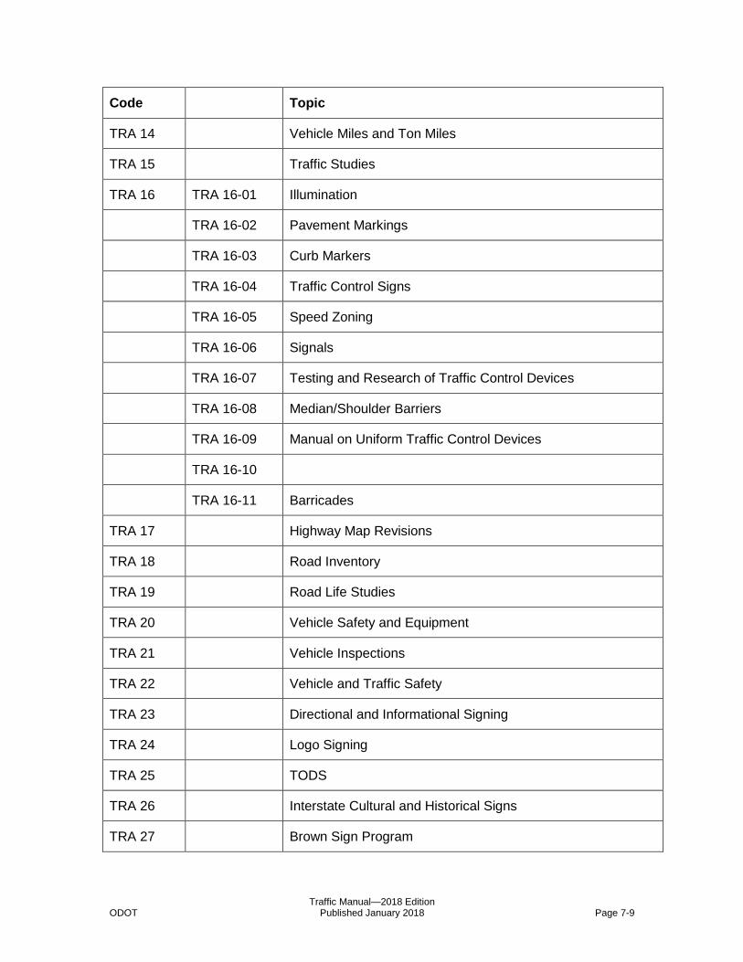
Traffic Manual—2018 Edition ODOT Published January 2018 Page 7-9
Code Topic
TRA 14 Vehicle Miles and Ton Miles
TRA 15 Traffic Studies
TRA 16 TRA 16-01 Illumination
TRA 16-02 Pavement Markings
TRA 16-03 Curb Markers
TRA 16-04 Traffic Control Signs
TRA 16-05 Speed Zoning
TRA 16-06 Signals
TRA 16-07 Testing and Research of Traffic Control Devices
TRA 16-08 Median/Shoulder Barriers
TRA 16-09 Manual on Uniform Traffic Control Devices
TRA 16-10
TRA 16-11 Barricades
TRA 17 Highway Map Revisions
TRA 18 Road Inventory
TRA 19 Road Life Studies
TRA 20 Vehicle Safety and Equipment
TRA 21 Vehicle Inspections
TRA 22 Vehicle and Traffic Safety
TRA 23 Directional and Informational Signing
TRA 24 Logo Signing
TRA 25 TODS
TRA 26 Interstate Cultural and Historical Signs
TRA 27 Brown Sign Program

Traffic Manual—2018 Edition ODOT Published January 2018 Page 7-10
Code Topic
TRA 28 Southern Oregon Regional Signing Study
TRA 29 Travel Publications
TRA 30 Grants of Access
TSO 01 Intelligent Transportation Systems (ITS) – General
TSO 02 ITS Reference Material – General
TSO 03 ITS Organizations
TSO 04 ITS Standards and Specifications
TSO 05 ITS Vendor Information
TSO 06 ITS Planning
TSO 08 ITS
TSO 09 ITS
TSO 10 ITS Projects
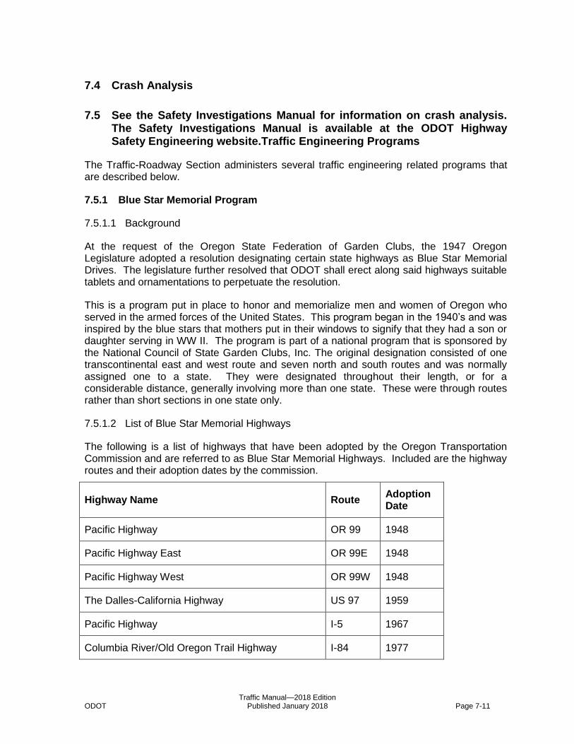
Traffic Manual—2018 Edition ODOT Published January 2018 Page 7-11
7.4 83B83BCrash Analysis
7.5 See the Safety Investigations Manual for information on crash analysis. The Safety Investigations Manual is available at the ODOT Highway Safety Engineering website. 84B84BTraffic Engineering Programs
The Traffic-Roadway Section administers several traffic engineering related programs that are described below.
7.5.1 199B199BBlue Star Memorial Program
7.5.1.1 344B344BBackground
At the request of the Oregon State Federation of Garden Clubs, the 1947 Oregon Legislature adopted a resolution designating certain state highways as Blue Star Memorial Drives. The legislature further resolved that ODOT shall erect along said highways suitable tablets and ornamentations to perpetuate the resolution.
This is a program put in place to honor and memorialize men and women of Oregon who served in the armed forces of the United States. This program began in the 1940’s and was inspired by the blue stars that mothers put in their windows to signify that they had a son or daughter serving in WW II. The program is part of a national program that is sponsored by the National Council of State Garden Clubs, Inc. The original designation consisted of one transcontinental east and west route and seven north and south routes and was normally assigned one to a state. They were designated throughout their length, or for a considerable distance, generally involving more than one state. These were through routes rather than short sections in one state only.
7.5.1.2 345B345BList of Blue Star Memorial Highways
The following is a list of highways that have been adopted by the Oregon Transportation Commission and are referred to as Blue Star Memorial Highways. Included are the highway routes and their adoption dates by the commission.
Highway Name Route Adoption Date
Pacific Highway OR 99 1948
Pacific Highway East OR 99E 1948
Pacific Highway West OR 99W 1948
The Dalles-California Highway US 97 1959
Pacific Highway I-5 1967
Columbia River/Old Oregon Trail Highway I-84 1977
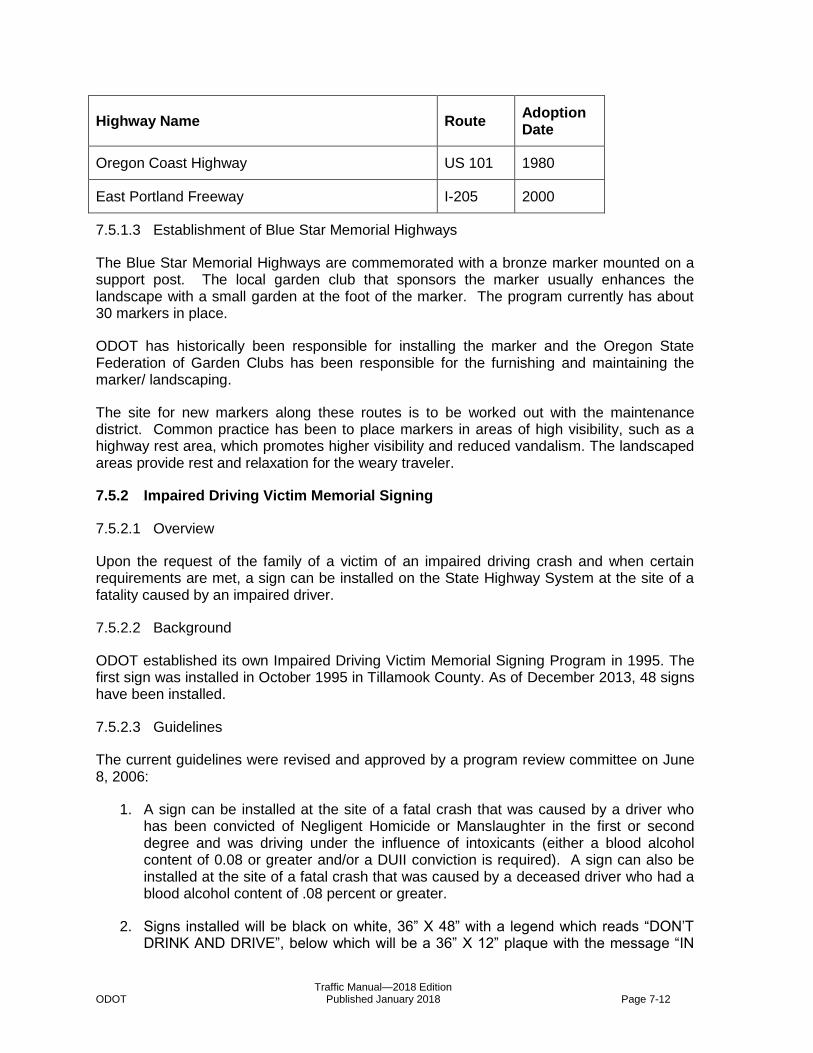
Traffic Manual—2018 Edition ODOT Published January 2018 Page 7-12
Highway Name Route Adoption Date
Oregon Coast Highway US 101 1980
East Portland Freeway I-205 2000
7.5.1.3 346B346BEstablishment of Blue Star Memorial Highways
The Blue Star Memorial Highways are commemorated with a bronze marker mounted on a support post. The local garden club that sponsors the marker usually enhances the landscape with a small garden at the foot of the marker. The program currently has about 30 markers in place.
ODOT has historically been responsible for installing the marker and the Oregon State Federation of Garden Clubs has been responsible for the furnishing and maintaining the marker/ landscaping.
The site for new markers along these routes is to be worked out with the maintenance district. Common practice has been to place markers in areas of high visibility, such as a highway rest area, which promotes higher visibility and reduced vandalism. The landscaped areas provide rest and relaxation for the weary traveler.
7.5.2 200B200BImpaired Driving Victim Memorial Signing
7.5.2.1 347B347BOverview
Upon the request of the family of a victim of an impaired driving crash and when certain requirements are met, a sign can be installed on the State Highway System at the site of a fatality caused by an impaired driver.
7.5.2.2 348B348BBackground
ODOT established its own Impaired Driving Victim Memorial Signing Program in 1995. The first sign was installed in October 1995 in Tillamook County. As of December 2013, 48 signs have been installed.
7.5.2.3 349B349BGuidelines
The current guidelines were revised and approved by a program review committee on June 8, 2006:
1. A sign can be installed at the site of a fatal crash that was caused by a driver who has been convicted of Negligent Homicide or Manslaughter in the first or second degree and was driving under the influence of intoxicants (either a blood alcohol content of 0.08 or greater and/or a DUII conviction is required). A sign can also be installed at the site of a fatal crash that was caused by a deceased driver who had a blood alcohol content of .08 percent or greater.
2. Signs installed will be black on white, 36” X 48” with a legend which reads “DON’T DRINK AND DRIVE”, below which will be a 36” X 12” plaque with the message “IN

Traffic Manual—2018 Edition ODOT Published January 2018 Page 7-13
MEMORY OF (Victim’s Name).” For cases involving controlled substances or inhalants the legend will read “DON’T USE DRUGS AND DRIVE”. Normally up to three names can be listed, but more than one name will require a larger plaque.
3. Each successful applicant will be entitled to one sign assembly as described above, mounted on one side of the post only (no back-to-back signs), facing oncoming traffic, and only on the side of the road nearest the lane of that oncoming traffic. In special situations where a sufficiently large turnout or wayside is available (as determined by Region Traffic Operations staff), and if acceptable to the applicant, a sign may be mounted parallel to the roadway rather than facing oncoming traffic.
4. Signs will be installed on state highways only if the sign location will meet ODOT standards shown in the Sign Policy and Guidelines for the State Highway System.
5. Signs will not be installed on the interstate system, freeways, or their ramps.
6. ODOT has no jurisdiction on county roads or city streets and thus cannot provide signs along these roadways.
7. The sign must be requested by the family of the victim or other sponsor and be paid for by the victim’s family or the sponsor. The sponsor need not be a family member, but any proposed installation must include agreement with an appropriate member of the victim’s family. If a given crash resulted in more than one fatality, and those fatalities were from different families, the applicant must contact the families of those other victims before application is made, in order to gain written concurrence on whether the sign should even be applied for, which names should appear on the sign, and how much each family will contribute toward the cost of the sign. Only one sign will be installed for any given crash.
8. Signs will cost $600. This amount is intended to cover expenses incurred, such as time spent on review of the application by the program coordinator, investigation of the proposed site by Region personnel, manufacture of the sign by the ODOT Sign Shop, and installation by the Maintenance District sign crew. Only one $600 check or money order will be accepted as payment for any successful application.
9. Region Traffic Operations staff will investigate all proposed installation sites and make a recommendation to the State Traffic-Roadway Engineer regarding sign placement. If the investigation determines that a location other than the one requested in the application is more appropriate, a distance of as much as one half mile away will be acceptable, with variations as approved by the State Traffic-Roadway Engineer. In no case, however, will the alternate location be on a highway other than the one on which the crash occurred.
10. The State Traffic-Roadway Engineer will approve or deny requests received and sign an agreement with sponsors and family members on those that are approved.
11. Signs will remain in place until they are weathered (usually seven to ten years). At that time, they will be removed. If a sign in serviceable condition is stolen, vandalized, or otherwise badly damaged, it will be replaced one time at ODOT expense. After a sign has been removed due to weathering, the original applicant may renew installation of the original sign by paying another $600.
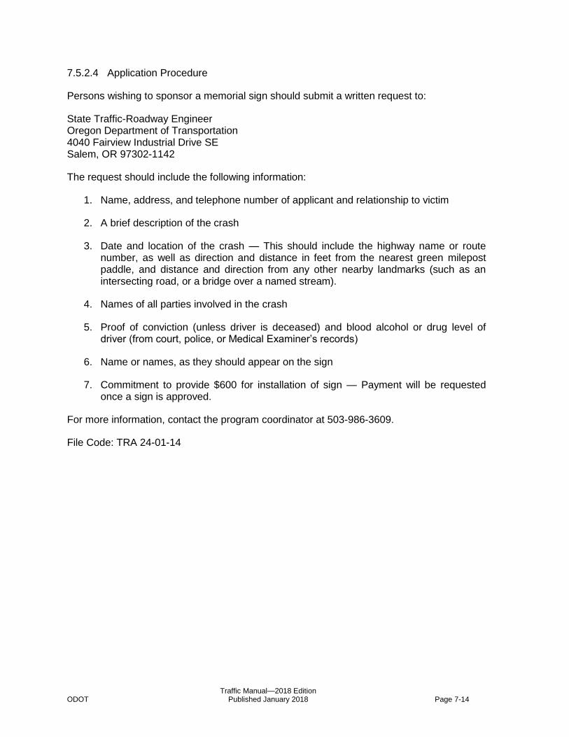
Traffic Manual—2018 Edition ODOT Published January 2018 Page 7-14
7.5.2.4 350B350BApplication Procedure
Persons wishing to sponsor a memorial sign should submit a written request to:
State Traffic-Roadway Engineer Oregon Department of Transportation 4040 Fairview Industrial Drive SE Salem, OR 97302-1142
The request should include the following information:
1. Name, address, and telephone number of applicant and relationship to victim
2. A brief description of the crash
3. Date and location of the crash — This should include the highway name or route number, as well as direction and distance in feet from the nearest green milepost paddle, and distance and direction from any other nearby landmarks (such as an intersecting road, or a bridge over a named stream).
4. Names of all parties involved in the crash
5. Proof of conviction (unless driver is deceased) and blood alcohol or drug level of driver (from court, police, or Medical Examiner’s records)
6. Name or names, as they should appear on the sign
7. Commitment to provide $600 for installation of sign — Payment will be requested once a sign is approved.
For more information, contact the program coordinator at 503-986-3609.
File Code: TRA 24-01-14
Traffic Manual—2018 Edition ODOT Published January 2018 Page 7-15
7.6 85B85BLegal Authority
References are made throughout this manual to Oregon Revised Statutes (ORS) and Oregon Administrative Rules (OAR). Several items of particular, general interest are highlighted below:
7.6.1 201B201BCrosswalks
ORS 801.220 defines crosswalks, ORS 811.010 and ORS 814.040 also apply to crosswalks and pedestrians. The Traffic Manual contains guidelines for determining when it is appropriate to mark crosswalks.
7.6.2 202B202BDelegation of Authority
The Oregon Transportation Commission, pursuant to ORS 184.635 and in order to provide for a more efficient and expeditious administration of the Department, delegates operations matters to the Chief Engineer (also called the Technical Services Manager). Matters dealing with traffic control devices are assigned to the State Traffic-Roadway Engineer by letter of authority and by OAR 734-020-0410.
7.6.3 203B203BEmergency Vehicle Preemption
The proper use of emergency vehicle preemption (traffic control signal operating) devices is described in ORS 815.440. The standards for installation, operation and use are defined in OAR 734-020-0300 through 734-020-0330.
7.6.4 204B204BFreeway Median Crossovers
The process and criteria for establishing freeway median crossovers is provided in OAR 734-020-0100 through 734-020-0115.
7.6.5 205B205BIncident Management
OAR 734-020-0145, OAR 734-020-0147, and OAR 734-020-0150 provide direction for the management of incidents or related activities. These OAR’s establish procedures for removal of spilled vehicle loads and wrecked vehicles from the travel portion of state highways; procedures for the removal of disabled, abandoned, or otherwise unattended vehicles on state highways; and procedures for the closure of highways when weather or road conditions constitute a danger of highway damage or a danger to the driving public, respectively.
7.6.6 206B206BJurisdiction
ORS 810.010 designates the bodies responsible for exercising jurisdiction over highways when the vehicle code requires the exercise of jurisdiction by the road authority. This section does not define maintenance responsibility.
Traffic Manual—2018 Edition ODOT Published January 2018 Page 7-16
7.6.7 207B207BMultiple Turns at Highway Intersections
The criteria for establishing multiple right and left turns at highway intersections are provided in OAR 734-020-0135 through 734-020-0140.
7.6.8 208B208BOne-way Operation, Transit Exceptions
ORS 810.130 allows road authorities to designate specific lanes or highways where vehicle traffic must proceed in one direction at all times or at times indicated by traffic control devices. This section also allows the designation of locations where public transit vehicles may proceed in a direction prohibited to other traffic.
7.6.9 209B209BParking Prohibitions
Each road authority has the authority to regulate, control and prohibit parking according to ORS 810.160. The process for establishing parking prohibitions or restrictions is defined in OAR 734-020-0020 and OAR 734-020-0080 through 734-020-0090.
7.6.10 210B210BRestrictions by Vehicle Type or Weight
ORS 810.030 allows the road authority to impose restrictions on highway use, by any or all vehicle types or weight classes, in order to protect the highway from damage or to protect the interest and safety of the general public. Restrictions or limitations imposed under this section must be imposed by proper order. This section does not grant authority to impose speed restrictions. Related administrative rules include OAR 734-020-0045, OAR 734-020-0080, and OAR 734-020-0100 through 0115 which prohibit non-motorized vehicles on certain highways; establish restrictions on overnight parking (non-emergency) on state highways; and provide for the use of freeway median crossovers, respectively.
7.6.11 211B211BSchool Zones
ORS 810.180 and ORS 811.111 cover the establishment of school speed zones. ORS 811.124, ORS 811.106, and ORS 811.235 also apply to school speed zones. ODOT’s A Guide to School Area Safety provides further information regarding school area safety.
7.6.12 212B212BSpeed Zones
ORS 810.180, ORS 811.100 through ORS 811.111 and OARs 734-020-0014, -0015, -0016, and -0017 cover the establishment of speed zones in the State of Oregon (See also ODOT’s Speed Zone Manual). Low volume roads and non-hard surfaced roads may be delegated to local jurisdictions.
7.6.13 213B213BTraffic Control Device, Appropriate Driver Responses
The appropriate driver response to traffic signal indications, including circular and arrow indications whether steady or flashing, lane direction control signals, stop signs and yield signs is provided by ORS 811.260. Turns made against a red indication are permitted under ORS 811.360. Appropriate responses to railroad crossing signals are provided by ORS 811.455.

Traffic Manual—2018 Edition ODOT Published January 2018 Page 7-17
7.6.14 214B214BTraffic Signal Approval Process
The Process that establishes consideration and approval for installation or removal of traffic signals on state highways is defined in OAR 734-020-0400 through 734-020-0500.
7.6.15 215B215BTransit and HOV Lanes
ORS 810.140 allows a road authority to designate bus or HOV lanes. Any restriction imposed must be imposed by proper order. OAR 734-020-0035 through 734-020-0043 contain the orders establishing such lanes. The only order currently in effect is OAR 734-020-0043 for the I-5 HOV Lanes in North Portland. Two such orders have been repealed - OAR 734-020-0035 for the Barber Boulevard (US 99 W Portland) Transit Lanes in 1977 and OAR 734-020-0040 for the Banfield (I-84 nee I-80N Portland) HOV Lanes in 1975. Both were repealed in September 1983. A third order – OAR 734-020-0042 - establishing temporary HOV Lanes on I-5 and I-205 during emergency repairs to the Interstate Bridge in the summer of 1997 expired in October 1997.
7.6.16 216B216BTurn Prohibitions
A description of the warrants and criteria for establishing U-turns at signalized intersections and turn prohibitions are described in OAR 734-020-0020, this authority is derived from ORS 810.210.
7.6.17 217B217BUniform Standards and Placement
ORS 810.200 and ORS 810.210 provide for the establishment of uniform standards and placement of traffic control devices. The Oregon Transportation Commission adopts the Manual on Uniform Traffic Control Devices, the Oregon Supplement to the MUTCD, and the Oregon Temporary Traffic Control Handbook by OAR 734-020-0005.
7.6.18 218B218BU-turn Designations
A description of the warrants and criteria for establishing U-turns at signalized intersections are described in OAR 734-020-0025, this authority is derived from ORS 810.130.

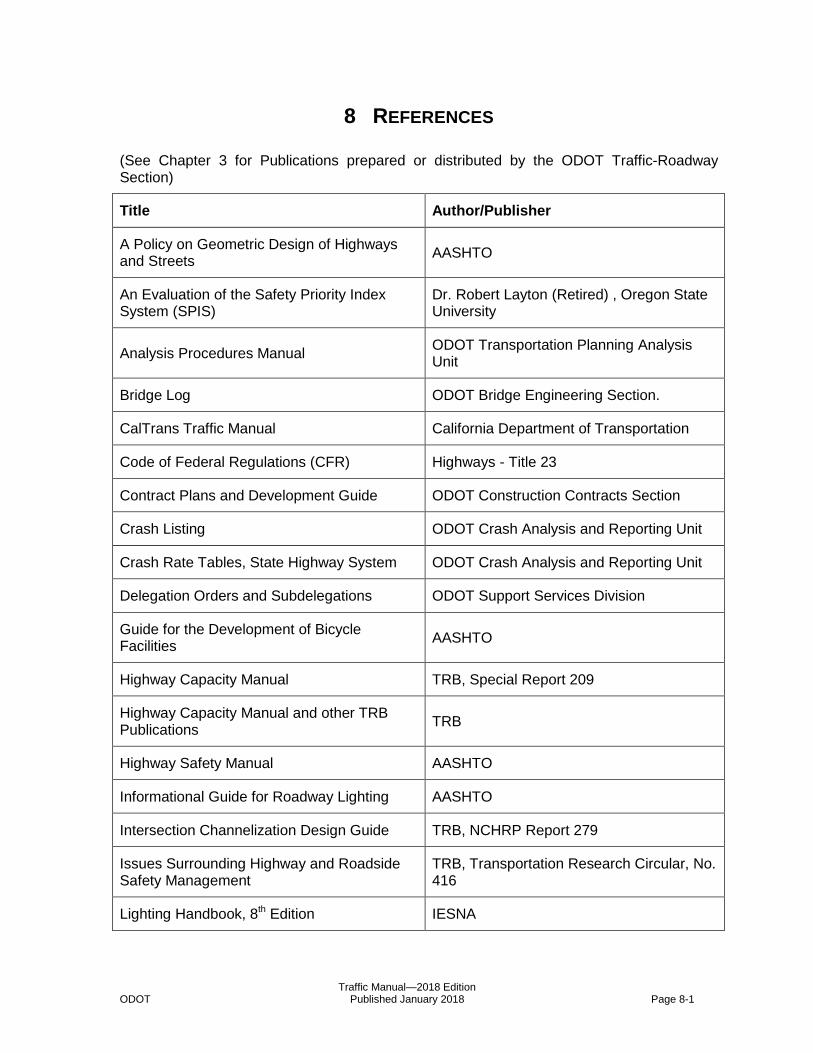
Traffic Manual—2018 Edition ODOT Published January 2018 Page 8-1
8 7B7BREFERENCES
(See Chapter 3 for Publications prepared or distributed by the ODOT Traffic-Roadway Section)
Title Author/Publisher
A Policy on Geometric Design of Highways and Streets
AASHTO
An Evaluation of the Safety Priority Index System (SPIS)
Dr. Robert Layton (Retired) , Oregon State University
Analysis Procedures Manual ODOT Transportation Planning Analysis Unit
Bridge Log ODOT Bridge Engineering Section.
CalTrans Traffic Manual California Department of Transportation
Code of Federal Regulations (CFR) Highways - Title 23
Contract Plans and Development Guide ODOT Construction Contracts Section
Crash Listing ODOT Crash Analysis and Reporting Unit
Crash Rate Tables, State Highway System ODOT Crash Analysis and Reporting Unit
Delegation Orders and Subdelegations ODOT Support Services Division
Guide for the Development of Bicycle Facilities
AASHTO
Highway Capacity Manual TRB, Special Report 209
Highway Capacity Manual and other TRB Publications
TRB
Highway Safety Manual AASHTO
Informational Guide for Roadway Lighting AASHTO
Intersection Channelization Design Guide TRB, NCHRP Report 279
Issues Surrounding Highway and Roadside Safety Management
TRB, Transportation Research Circular, No. 416
Lighting Handbook, 8th Edition IESNA
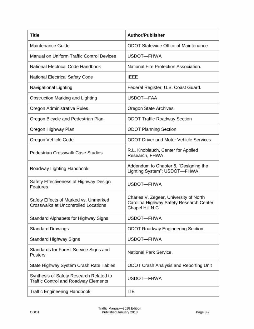
Traffic Manual—2018 Edition ODOT Published January 2018 Page 8-2
Title Author/Publisher
Maintenance Guide ODOT Statewide Office of Maintenance
Manual on Uniform Traffic Control Devices USDOT—FHWA
National Electrical Code Handbook National Fire Protection Association.
National Electrical Safety Code IEEE
Navigational Lighting Federal Register; U.S. Coast Guard.
Obstruction Marking and Lighting USDOT—FAA
Oregon Administrative Rules Oregon State Archives
Oregon Bicycle and Pedestrian Plan ODOT Traffic-Roadway Section
Oregon Highway Plan ODOT Planning Section
Oregon Vehicle Code ODOT Driver and Motor Vehicle Services
Pedestrian Crosswalk Case Studies R.L. Knoblauch, Center for Applied Research, FHWA
Roadway Lighting Handbook Addendum to Chapter 6, “Designing the Lighting System”; USDOT—FHWA
Safety Effectiveness of Highway Design Features
USDOT—FHWA
Safety Effects of Marked vs. Unmarked Crosswalks at Uncontrolled Locations
Charles V. Zegeer, University of North Carolina Highway Safety Research Center, Chapel Hill N.C
Standard Alphabets for Highway Signs USDOT—FHWA
Standard Drawings ODOT Roadway Engineering Section
Standard Highway Signs USDOT—FHWA
Standards for Forest Service Signs and Posters
National Park Service.
State Highway System Crash Rate Tables ODOT Crash Analysis and Reporting Unit
Synthesis of Safety Research Related to Traffic Control and Roadway Elements
USDOT—FHWA
Traffic Engineering Handbook ITE
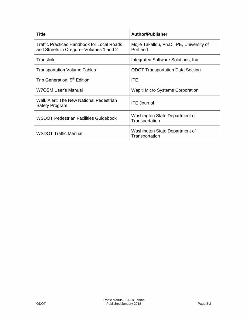
Traffic Manual—2018 Edition ODOT Published January 2018 Page 8-3
Title Author/Publisher
Traffic Practices Handbook for Local Roads and Streets in Oregon—Volumes 1 and 2
Mojie Takallou, Ph.D., PE, University of Portland
Translink Integrated Software Solutions, Inc.
Transportation Volume Tables ODOT Transportation Data Section
Trip Generation, 5th Edition ITE
W7OSM User’s Manual Wapiti Micro Systems Corporation
Walk Alert: The New National Pedestrian Safety Program
ITE Journal
WSDOT Pedestrian Facilities Guidebook Washington State Department of Transportation
WSDOT Traffic Manual Washington State Department of Transportation

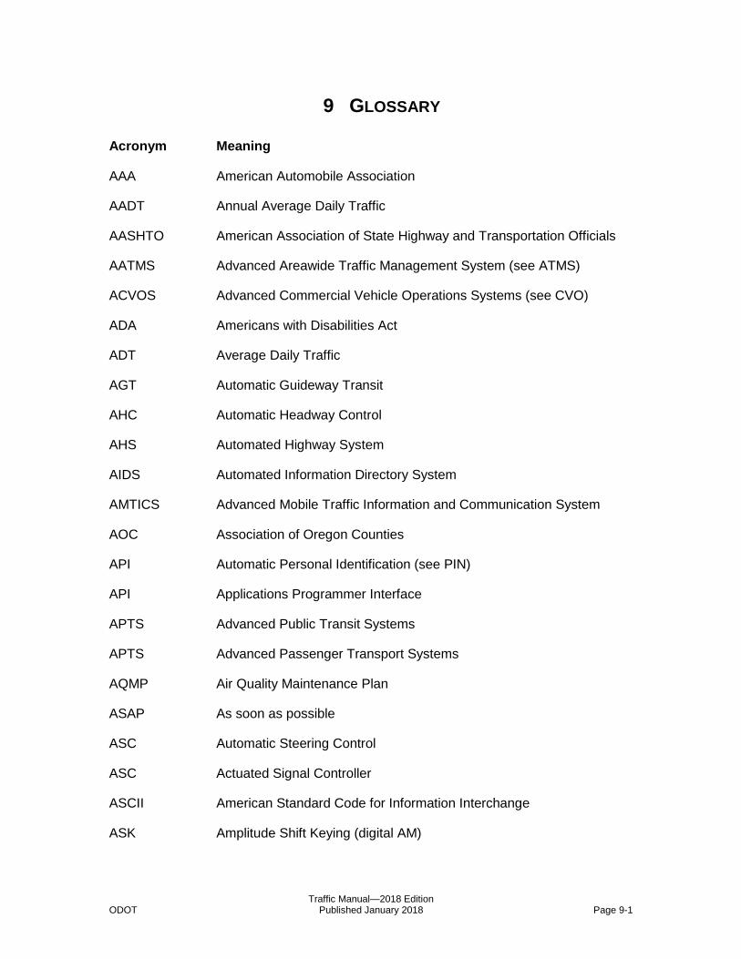
Traffic Manual—2018 Edition ODOT Published January 2018 Page 9-1
9 8B8BGLOSSARY
Acronym Meaning
AAA American Automobile Association
AADT Annual Average Daily Traffic
AASHTO American Association of State Highway and Transportation Officials
AATMS Advanced Areawide Traffic Management System (see ATMS)
ACVOS Advanced Commercial Vehicle Operations Systems (see CVO)
ADA Americans with Disabilities Act
ADT Average Daily Traffic
AGT Automatic Guideway Transit
AHC Automatic Headway Control
AHS Automated Highway System
AIDS Automated Information Directory System
AMTICS Advanced Mobile Traffic Information and Communication System
AOC Association of Oregon Counties
API Automatic Personal Identification (see PIN)
API Applications Programmer Interface
APTS Advanced Public Transit Systems
APTS Advanced Passenger Transport Systems
AQMP Air Quality Maintenance Plan
ASAP As soon as possible
ASC Automatic Steering Control
ASC Actuated Signal Controller
ASCII American Standard Code for Information Interchange
ASK Amplitude Shift Keying (digital AM)
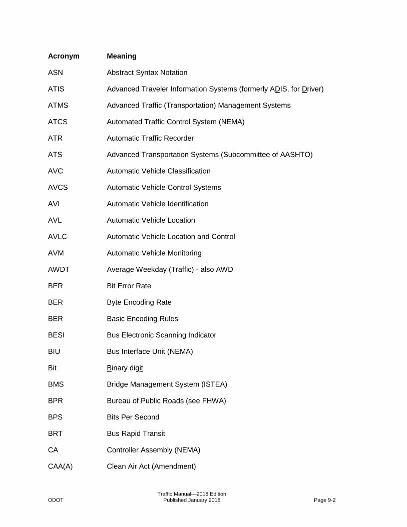
Traffic Manual—2018 Edition ODOT Published January 2018 Page 9-2
Acronym Meaning
ASN Abstract Syntax Notation
ATIS Advanced Traveler Information Systems (formerly ADIS, for Driver)
ATMS Advanced Traffic (Transportation) Management Systems
ATCS Automated Traffic Control System (NEMA)
ATR Automatic Traffic Recorder
ATS Advanced Transportation Systems (Subcommittee of AASHTO)
AVC Automatic Vehicle Classification
AVCS Automatic Vehicle Control Systems
AVI Automatic Vehicle Identification
AVL Automatic Vehicle Location
AVLC Automatic Vehicle Location and Control
AVM Automatic Vehicle Monitoring
AWDT Average Weekday (Traffic) - also AWD
BER Bit Error Rate
BER Byte Encoding Rate
BER Basic Encoding Rules
BESI Bus Electronic Scanning Indicator
BIU Bus Interface Unit (NEMA)
Bit Binary digit
BMS Bridge Management System (ISTEA)
BPR Bureau of Public Roads (see FHWA)
BPS Bits Per Second
BRT Bus Rapid Transit
CA Controller Assembly (NEMA)
CAA(A) Clean Air Act (Amendment)

Traffic Manual—2018 Edition ODOT Published January 2018 Page 9-3
Acronym Meaning
CAD Call / Active Display (Model 170 Microprocessor Traffic Controllers)
CAD Computer Aided Design (Drafting)
CAD Computer Aided Dispatching
CADD Computer Aided Drafting and Design
CalTrans California Department of Transportation
CAO Chief Administrative Officer
CAR Crash Analysis and Reporting
CAT Countermeasure Analysis Tool
CBD Central Business District
CCTV Closed Circuit Television Camera(s)
CDL Commercial Driver’s License
CD-ROM Compact Disk - Read Only Memory
CFR Code of Federal Regulations
CHEMTREC Chemical Transportation Emergency Center
CMAQ Congestion Management Air Quality
CMS Changeable Message Sign(s) (see VMS - preferred)
CMS Congestion Management System (ISTEA)
COATS California Oregon Advanced Transportation Systems
COP City of Portland (Prineville)
COTS Commercial Off-the-Shelf computer software and/or hardware
CPFF Cost Plus Fixed Fee
CPU Central Processing Unit
CRC Cyclic Redundancy Check
CSR Crash Summary Report
CTWLTL Continuous Two Way Left Turn Lane
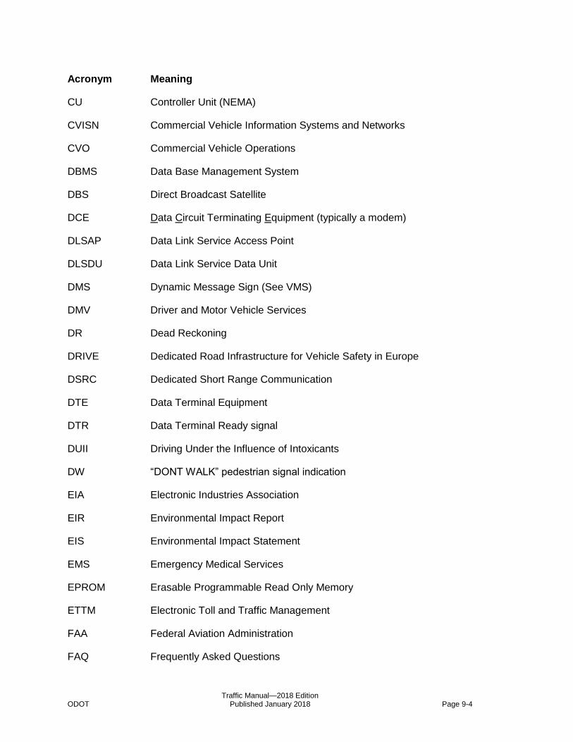
Traffic Manual—2018 Edition ODOT Published January 2018 Page 9-4
Acronym Meaning
CU Controller Unit (NEMA)
CVISN Commercial Vehicle Information Systems and Networks
CVO Commercial Vehicle Operations
DBMS Data Base Management System
DBS Direct Broadcast Satellite
DCE Data Circuit Terminating Equipment (typically a modem)
DLSAP Data Link Service Access Point
DLSDU Data Link Service Data Unit
DMS Dynamic Message Sign (See VMS)
DMV Driver and Motor Vehicle Services
DR Dead Reckoning
DRIVE Dedicated Road Infrastructure for Vehicle Safety in Europe
DSRC Dedicated Short Range Communication
DTE Data Terminal Equipment
DTR Data Terminal Ready signal
DUII Driving Under the Influence of Intoxicants
DW “DONT WALK” pedestrian signal indication
EIA Electronic Industries Association
EIR Environmental Impact Report
EIS Environmental Impact Statement
EMS Emergency Medical Services
EPROM Erasable Programmable Read Only Memory
ETTM Electronic Toll and Traffic Management
FAA Federal Aviation Administration
FAQ Frequently Asked Questions
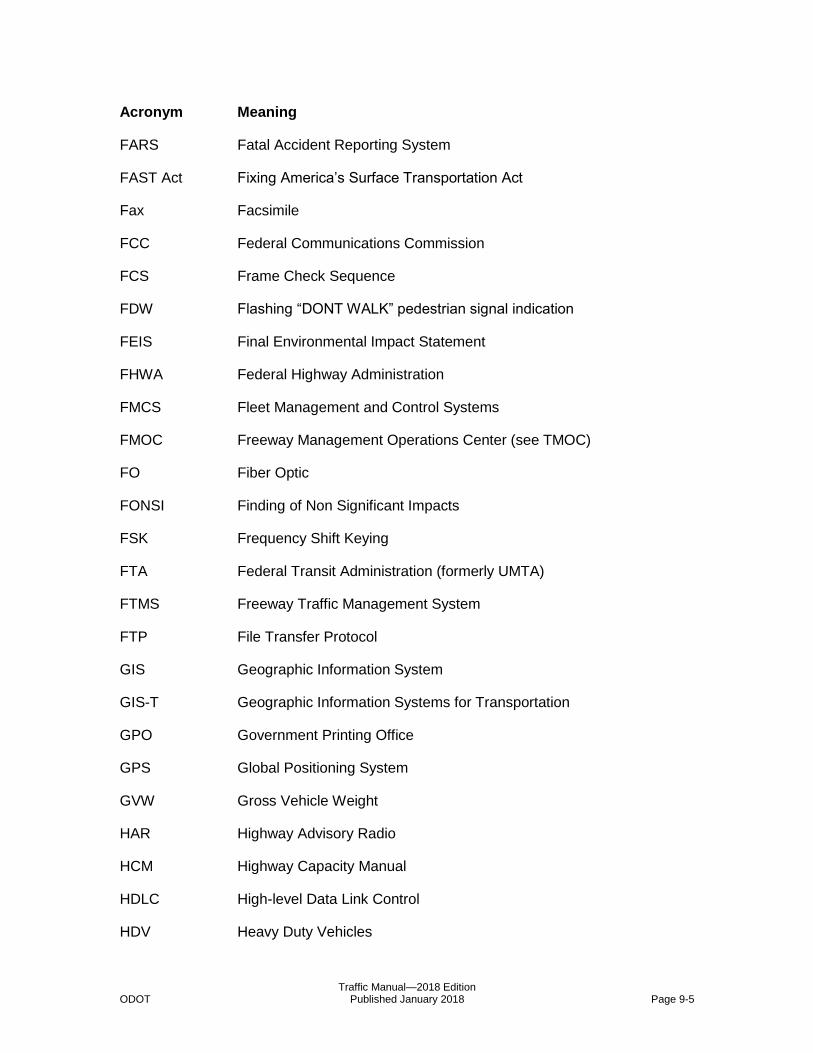
Traffic Manual—2018 Edition ODOT Published January 2018 Page 9-5
Acronym Meaning
FARS Fatal Accident Reporting System
FAST Act Fixing America’s Surface Transportation Act
Fax Facsimile
FCC Federal Communications Commission
FCS Frame Check Sequence
FDW Flashing “DONT WALK” pedestrian signal indication
FEIS Final Environmental Impact Statement
FHWA Federal Highway Administration
FMCS Fleet Management and Control Systems
FMOC Freeway Management Operations Center (see TMOC)
FO Fiber Optic
FONSI Finding of Non Significant Impacts
FSK Frequency Shift Keying
FTA Federal Transit Administration (formerly UMTA)
FTMS Freeway Traffic Management System
FTP File Transfer Protocol
GIS Geographic Information System
GIS-T Geographic Information Systems for Transportation
GPO Government Printing Office
GPS Global Positioning System
GVW Gross Vehicle Weight
HAR Highway Advisory Radio
HCM Highway Capacity Manual
HDLC High-level Data Link Control
HDV Heavy Duty Vehicles
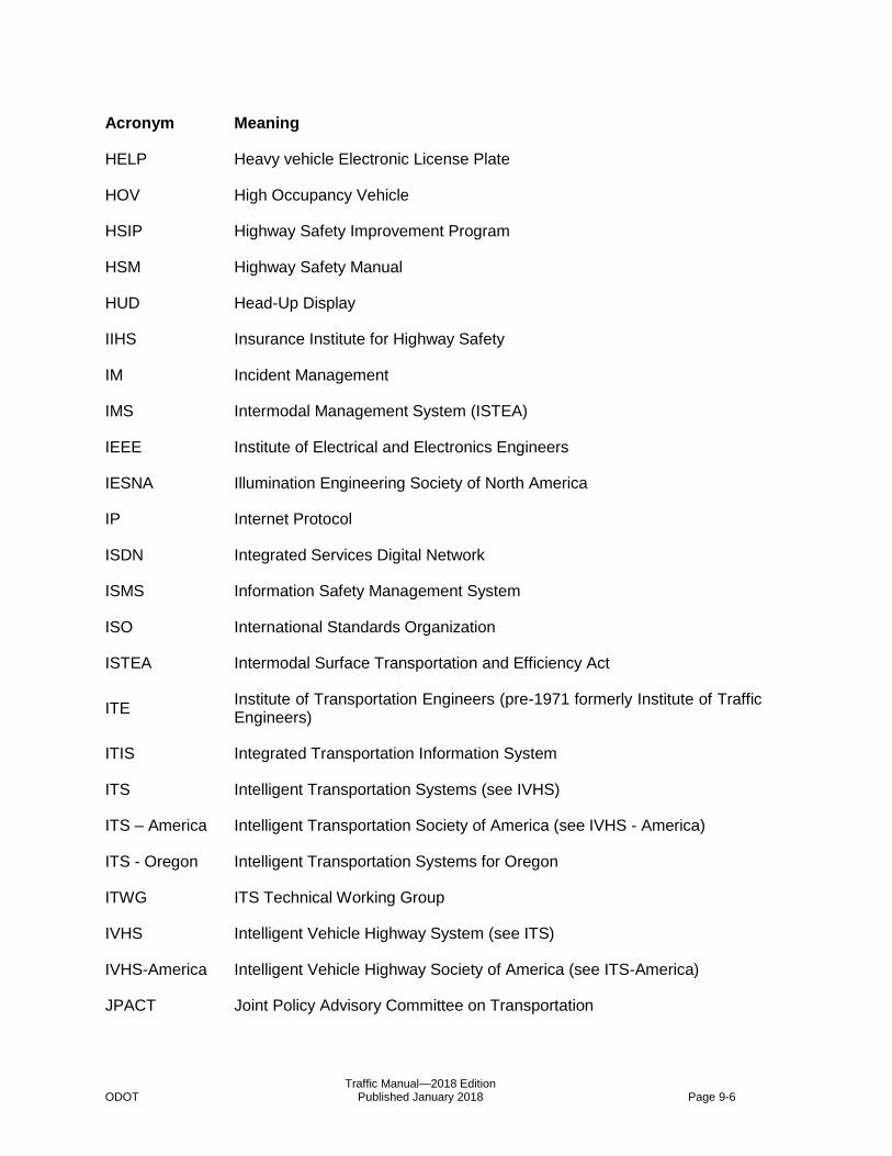
Traffic Manual—2018 Edition ODOT Published January 2018 Page 9-6
Acronym Meaning
HELP Heavy vehicle Electronic License Plate
HOV High Occupancy Vehicle
HSIP Highway Safety Improvement Program
HSM Highway Safety Manual
HUD Head-Up Display
IIHS Insurance Institute for Highway Safety
IM Incident Management
IMS Intermodal Management System (ISTEA)
IEEE Institute of Electrical and Electronics Engineers
IESNA Illumination Engineering Society of North America
IP Internet Protocol
ISDN Integrated Services Digital Network
ISMS Information Safety Management System
ISO International Standards Organization
ISTEA Intermodal Surface Transportation and Efficiency Act
ITE Institute of Transportation Engineers (pre-1971 formerly Institute of Traffic Engineers)
ITIS Integrated Transportation Information System
ITS Intelligent Transportation Systems (see IVHS)
ITS – America Intelligent Transportation Society of America (see IVHS - America)
ITS - Oregon Intelligent Transportation Systems for Oregon
ITWG ITS Technical Working Group
IVHS Intelligent Vehicle Highway System (see ITS)
IVHS-America Intelligent Vehicle Highway Society of America (see ITS-America)
JPACT Joint Policy Advisory Committee on Transportation
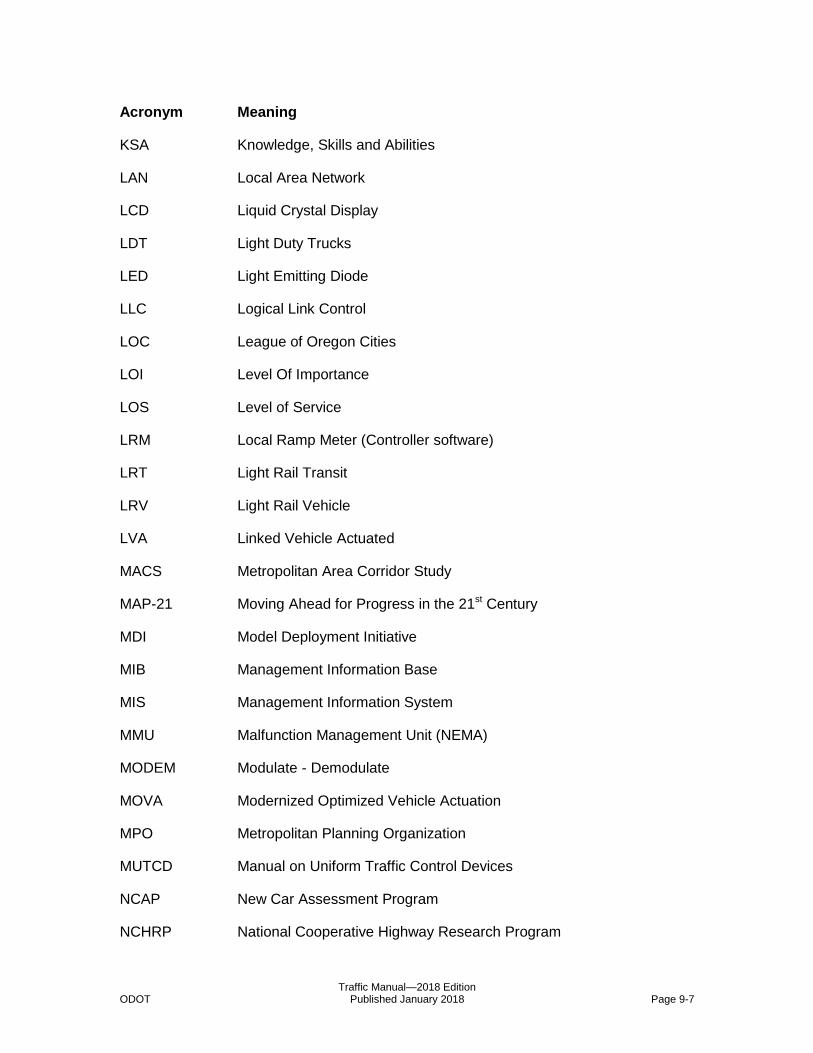
Traffic Manual—2018 Edition ODOT Published January 2018 Page 9-7
Acronym Meaning
KSA Knowledge, Skills and Abilities
LAN Local Area Network
LCD Liquid Crystal Display
LDT Light Duty Trucks
LED Light Emitting Diode
LLC Logical Link Control
LOC League of Oregon Cities
LOI Level Of Importance
LOS Level of Service
LRM Local Ramp Meter (Controller software)
LRT Light Rail Transit
LRV Light Rail Vehicle
LVA Linked Vehicle Actuated
MACS Metropolitan Area Corridor Study
MAP-21 Moving Ahead for Progress in the 21st Century
MDI Model Deployment Initiative
MIB Management Information Base
MIS Management Information System
MMU Malfunction Management Unit (NEMA)
MODEM Modulate - Demodulate
MOVA Modernized Optimized Vehicle Actuation
MPO Metropolitan Planning Organization
MUTCD Manual on Uniform Traffic Control Devices
NCAP New Car Assessment Program
NCHRP National Cooperative Highway Research Program
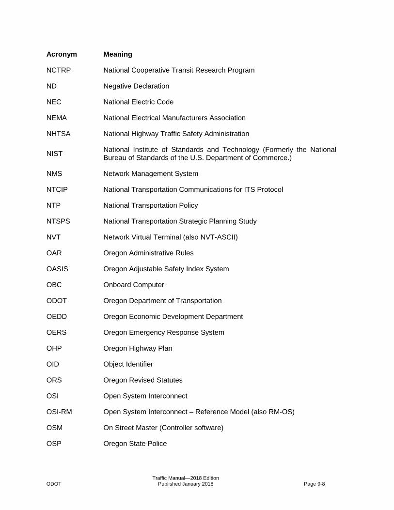
Traffic Manual—2018 Edition ODOT Published January 2018 Page 9-8
Acronym Meaning
NCTRP National Cooperative Transit Research Program
ND Negative Declaration
NEC National Electric Code
NEMA National Electrical Manufacturers Association
NHTSA National Highway Traffic Safety Administration
NIST National Institute of Standards and Technology (Formerly the National Bureau of Standards of the U.S. Department of Commerce.)
NMS Network Management System
NTCIP National Transportation Communications for ITS Protocol
NTP National Transportation Policy
NTSPS National Transportation Strategic Planning Study
NVT Network Virtual Terminal (also NVT-ASCII)
OAR Oregon Administrative Rules
OASIS Oregon Adjustable Safety Index System
OBC Onboard Computer
ODOT Oregon Department of Transportation
OEDD Oregon Economic Development Department
OERS Oregon Emergency Response System
OHP Oregon Highway Plan
OID Object Identifier
ORS Oregon Revised Statutes
OSI Open System Interconnect
OSI-RM Open System Interconnect – Reference Model (also RM-OS)
OSM On Street Master (Controller software)
OSP Oregon State Police
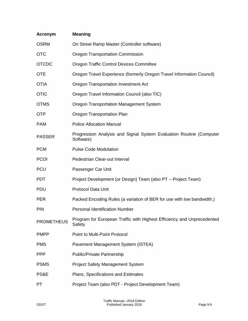
Traffic Manual—2018 Edition ODOT Published January 2018 Page 9-9
Acronym Meaning
OSRM On Street Ramp Master (Controller software)
OTC Oregon Transportation Commission
OTCDC Oregon Traffic Control Devices Committee
OTE Oregon Travel Experience (formerly Oregon Travel Information Council)
OTIA Oregon Transportation Investment Act
OTIC Oregon Travel Information Council (also TIC)
OTMS Oregon Transportation Management System
OTP Oregon Transportation Plan
PAM Police Allocation Manual
PASSER Progression Analysis and Signal System Evaluation Routine (Computer Software)
PCM Pulse Code Modulation
PCOI Pedestrian Clear-out Interval
PCU Passenger Car Unit
PDT Project Development (or Design) Team (also PT – Project Team)
PDU Protocol Data Unit
PER Packed Encoding Rules (a variation of BER for use with low bandwidth.)
PIN Personal Identification Number
PROMETHEUS Program for European Traffic with Highest Efficiency and Unprecedented Safety
PMPP Point to Multi-Point Protocol
PMS Pavement Management System (ISTEA)
PPP Public/Private Partnership
PSMS Project Safety Management System
PS&E Plans, Specifications and Estimates
PT Project Team (also PDT - Project Development Team)
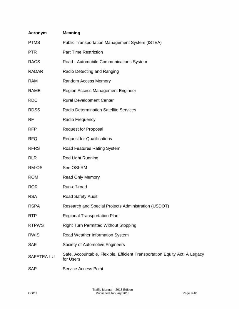
Traffic Manual—2018 Edition ODOT Published January 2018 Page 9-10
Acronym Meaning
PTMS Public Transportation Management System (ISTEA)
PTR Part Time Restriction
RACS Road - Automobile Communications System
RADAR Radio Detecting and Ranging
RAM Random Access Memory
RAME Region Access Management Engineer
RDC Rural Development Center
RDSS Radio Determination Satellite Services
RF Radio Frequency
RFP Request for Proposal
RFQ Request for Qualifications
RFRS Road Features Rating System
RLR Red Light Running
RM-OS See OSI-RM
ROM Read Only Memory
ROR Run-off-road
RSA Road Safety Audit
RSPA Research and Special Projects Administration (USDOT)
RTP Regional Transportation Plan
RTPWS Right Turn Permitted Without Stopping
RWIS Road Weather Information System
SAE Society of Automotive Engineers
SAFETEA-LU Safe, Accountable, Flexible, Efficient Transportation Equity Act: A Legacy for Users
SAP Service Access Point
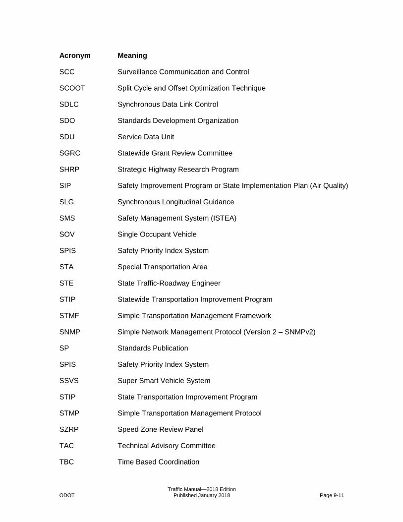
Traffic Manual—2018 Edition ODOT Published January 2018 Page 9-11
Acronym Meaning
SCC Surveillance Communication and Control
SCOOT Split Cycle and Offset Optimization Technique
SDLC Synchronous Data Link Control
SDO Standards Development Organization
SDU Service Data Unit
SGRC Statewide Grant Review Committee
SHRP Strategic Highway Research Program
SIP Safety Improvement Program or State Implementation Plan (Air Quality)
SLG Synchronous Longitudinal Guidance
SMS Safety Management System (ISTEA)
SOV Single Occupant Vehicle
SPIS Safety Priority Index System
STA Special Transportation Area
STE State Traffic-Roadway Engineer
STIP Statewide Transportation Improvement Program
STMF Simple Transportation Management Framework
SNMP Simple Network Management Protocol (Version 2 – SNMPv2)
SP Standards Publication
SPIS Safety Priority Index System
SSVS Super Smart Vehicle System
STIP State Transportation Improvement Program
STMP Simple Transportation Management Protocol
SZRP Speed Zone Review Panel
TAC Technical Advisory Committee
TBC Time Based Coordination
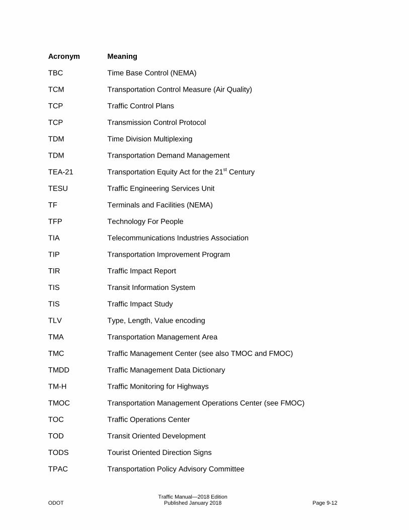
Traffic Manual—2018 Edition ODOT Published January 2018 Page 9-12
Acronym Meaning
TBC Time Base Control (NEMA)
TCM Transportation Control Measure (Air Quality)
TCP Traffic Control Plans
TCP Transmission Control Protocol
TDM Time Division Multiplexing
TDM Transportation Demand Management
TEA-21 Transportation Equity Act for the 21st Century
TESU Traffic Engineering Services Unit
TF Terminals and Facilities (NEMA)
TFP Technology For People
TIA Telecommunications Industries Association
TIP Transportation Improvement Program
TIR Traffic Impact Report
TIS Transit Information System
TIS Traffic Impact Study
TLV Type, Length, Value encoding
TMA Transportation Management Area
TMC Traffic Management Center (see also TMOC and FMOC)
TMDD Traffic Management Data Dictionary
TM-H Traffic Monitoring for Highways
TMOC Transportation Management Operations Center (see FMOC)
TOC Traffic Operations Center
TOD Transit Oriented Development
TODS Tourist Oriented Direction Signs
TPAC Transportation Policy Advisory Committee

Traffic Manual—2018 Edition ODOT Published January 2018 Page 9-13
Acronym Meaning
TPAU Transportation Planning and Analysis Unit
TPR Transportation Planning Rule
TPST Traffic Project Services Team
TRANSYT Traffic Network Study Tool (Computer Software)
TRB Transportation Research Board
TRL Time Reference Line
TRRL Transportation and Road Research Laboratory
TRS Traffic-Roadway Section
TSAMU Traffic Standards and Asset Management Unit
TSM Technical Services Manager
TSM Transitway Simulation Model
TSM Transportation System Management
TSO Telephone Service Order
TSO Transportation System Operations
TSP Transportation System Plan
TSSU Traffic Systems Services Unit
TTI Texas Transportation Institute
TWLTL Two Way Left Turn Lane (or CTWLTL for Continuous Two Way Left Turn Lane)
UBA Urban Business Area
UDP User Datagram Protocol
UHF Ultra High Frequency (300MHz to 3GHz)
UMTA Urban Mass Transit Administration (see FTA)
USDOT United States Department of Transportation (also DOT)
UTC Urban Traffic Control
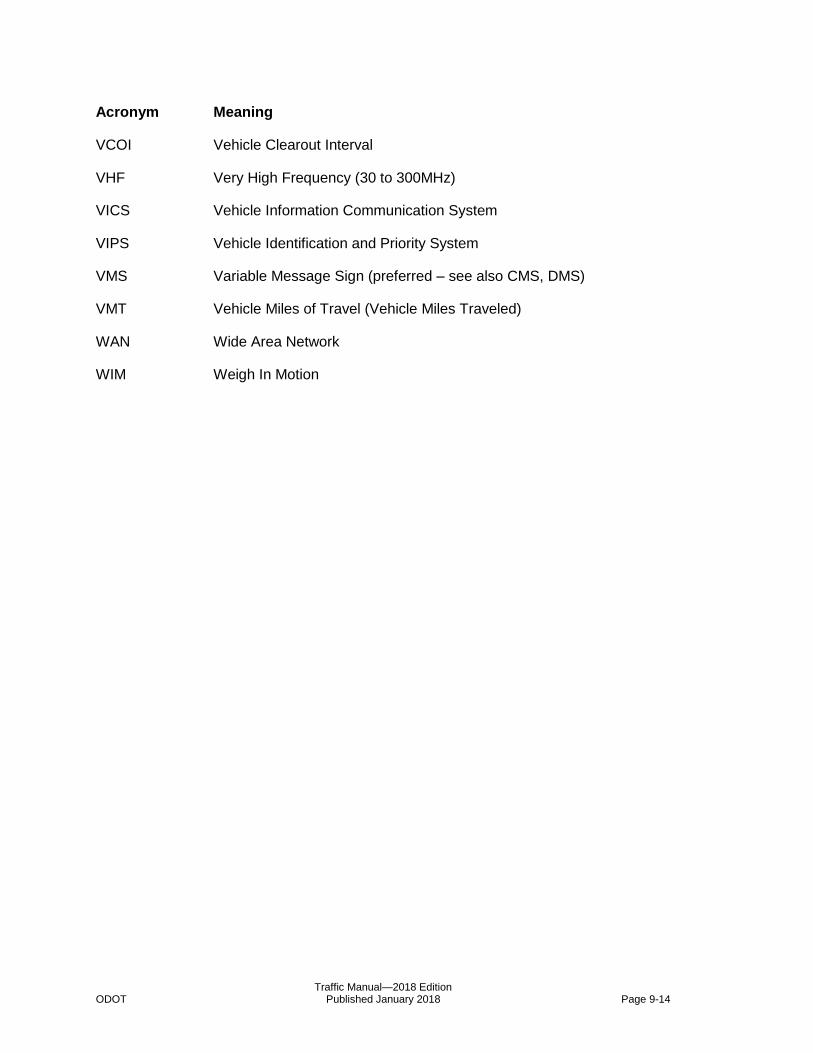
Traffic Manual—2018 Edition ODOT Published January 2018 Page 9-14
Acronym Meaning
VCOI Vehicle Clearout Interval
VHF Very High Frequency (30 to 300MHz)
VICS Vehicle Information Communication System
VIPS Vehicle Identification and Priority System
VMS Variable Message Sign (preferred – see also CMS, DMS)
VMT Vehicle Miles of Travel (Vehicle Miles Traveled)
WAN Wide Area Network
WIM Weigh In Motion