ODISHA POWER TRANSMISSION CORPORATION LIMITED · ODISHA POWER TRANSMISSION CORPORATION LIMITED (1)...
32
SCOPE OF WORKS-VOL-IIA “Package 19-01, 19-02,19-03 & 19-04” 1/2 ODISHA POWER TRANSMISSION CORPORATION LIMITED (1)PACKAGE 19-01 : Construction of 132kv S/C line on D/C tower from 132/33kv Grid S/s, Nuapatana to 132/33kv Grid S/s, Banki along with 01no 132kv feeder bay extension at both ends on TURNKEY BASIS. (2 PACKAGE 19-02: Construction of 132kv S/c line on DC tower from 132/33kv, Grid S/s Nuapada to 132/33kv Grid S/s, Padampur along with 01no 132kv feeder bay extension at both ends on TURNKEY BASIS. (3) PACKAGE 19-03: Construction of 132kv LILO line from 132kv Burla-Chipilima Tie line to 220/132/33kv A.Katapalli Grid S/s along with 02nos of 132kv feeder bay extension at 220/132/33kv A.Katapalli Grid S/s on TURNKEY BASIS. (4) PACKAGE 19-04: Construction of 132kv S/c Line on D/C tower from 220/132/33kv Grid S/s Bhadrak to 132/33kv Grid S/s, Anandpur along with 01no 132kv feeder bay extension at both ends & on TURNKEY BASIS. VOL-IIA SCOPE OF WORKS NOTICE INVITING TENDER-NIT NO. 19 / 2013-14 TENDER SPECIFICATION NO Sr. G.M-CPC- Tender- Package –19-01, 19-02, 19-03 & 19-04 / 2013-14 IMPORTANT NOTE THE BIDDERS ARE ADVISED TO VISIT THE SITE BEFORE QUOTING THE BID. THEY SHALL ASCERTAIN ALL THE DATA FOR TURNKEY COMPLETION OF THE SUBSTATION AND ASSOCIATED TRANSMISSION LINES SUCH AS:-
-
Upload
trinhnguyet -
Category
Documents
-
view
242 -
download
1
Transcript of ODISHA POWER TRANSMISSION CORPORATION LIMITED · ODISHA POWER TRANSMISSION CORPORATION LIMITED (1)...

SCOPE OF WORKS-VOL-IIA “Package 19-01, 19-02,19-03 & 19-04” 1/2
ODISHA POWER TRANSMISSION CORPORATION LIMITED
(1)PACKAGE 19-01: Construction of 132kv S/C line on D/C tower from 132/33kv Grid S/s, Nuapatana to 132/33kv Grid S/s, Banki along with 01no 132kv feeder bay extension at both ends on TURNKEY BASIS. (2 PACKAGE 19-02: Construction of 132kv S/c line on DC tower from 132/33kv, Grid S/s Nuapada to 132/33kv Grid S/s, Padampur along with 01no 132kv feeder bay extension at both ends on TURNKEY BASIS. (3) PACKAGE 19-03: Construction of 132kv LILO line from 132kv Burla-Chipilima Tie line to 220/132/33kv A.Katapalli Grid S/s along with 02nos of 132kv feeder bay extension at 220/132/33kv A.Katapalli Grid S/s on TURNKEY BASIS. (4) PACKAGE 19-04: Construction of 132kv S/c Line on D/C tower from 220/132/33kv Grid S/s Bhadrak to 132/33kv Grid S/s, Anandpur along with 01no 132kv feeder bay extension at both ends & on TURNKEY BASIS.
VOL-IIA SCOPE OF WORKS
NOTICE INVITING TENDER-NIT NO. 19 / 2013-14
TENDER SPECIFICATION NO Sr. G.M-CPC- Tender- Package –19-01, 19-02, 19-03 & 19-04 / 2013-14
IMPORTANT NOTE
THE BIDDERS ARE ADVISED TO VISIT THE SITE BEFORE QUOTING THE BID. THEY SHALL ASCERTAIN ALL THE DATA FOR TURNKEY COMPLETION OF THE SUBSTATION AND ASSOCIATED TRANSMISSION LINES SUCH AS:-

SCOPE OF WORKS-VOL-IIA “Package 19-01, 19-02,19-03 & 19-04” 2/2
1. SOIL BEARING CAPABILITY.
2. BENCHING AND FILLING FOR SITE LEVELLING.
3. TYPE OF STRUCTURES FOR BOTH LINE & SUBSTATION.
4. QUANTITY OF MATERIALS/STRUCTURES/EQUIPMENT.
5. TYPE OF FOUNDATIONS FOR LINE TOWERS & SUB STATION EQUIPMENT/STRUCTURES.
6. THE LENGTH OF THE BOUNDARY WALL, FENCING AND ROADS.
7. ANY OTHER DATA REQUIRED FOR DESIGNING THE LINE & SUBSTATION.

SCOPE OF WORKS-VOL-IIA “Package 19-01, 19-02,19-03 & 19-04” 1/30
SCOPE OF WORK:- 1. General The Employer (M/S ODISHA POWER TRANSMISSION CORPOTATION LIMITED.) is strengthening their Transmission and Distribution systems by way of constructing the following sub-stations and transmission lines package wise in the state of Odisha as outlined in the detailed scope of work. The indicative layout diagram & SLD of the proposed sub-station are enclosed in the drawing folder in Vol-II. The works are to be carried out on Turnkey Basis till final commissioning of substation associated transmission lines, its testing, commissioning and handing over the same to the owner. FOLLOWINGS ARE THE NAME OF THE PACKAGES: (1)PACKAGE 19-01: Construction of 132kv S/C line on D/C tower from 132/33kv Grid S/s, Nuapatana to 132/33kv Grid S/s, Banki along with 01no 132kv feeder bay extension at both ends on TURNKEY BASIS. (2 PACKAGE 19-02: Construction of 132kv S/c line on DC tower from 132/33kv, Grid S/s Nuapada to 132/33kv Grid S/s, Padampur along with 01no 132kv feeder bay extension at both ends on TURNKEY BASIS. (3) PACKAGE 19-03: Construction of 132kv LILO line from 132kv Burla-Chipilima Tie line to 220/132/33kv A.Katapalli Grid S/s along with 02nos of 132kv feeder bay extension at 220/132/33kv A.Katapalli Grid S/s on TURNKEY BASIS. (4) PACKAGE 19-04: Construction of 132kv S/c Line on D/C tower from 220/132/33kv Grid S/s Bhadrak to 132/33kv Grid S/s, Anandpur along with 01no 132kv feeder bay extension at both ends & on TURNKEY BASIS.
The scope of the work includes:- i) Design, manufacture, testing, supply & commissioning of all equipment for substation and transmission lines, as detailed in the specifications and schedule of quantities and in subsequent clauses except supply of Auto and Power Transformer and PLCC indoor equipment, which shall be supplied by the Employer. The contractor shall load, unload, transport, erect, connect to the system, test and commission the Auto Transformer, Power transformer & the PLCC equipment. Installation of PLCC equipment at remote (existing) end and proposed end of the sub-station or any modification shall be under the scope of the contractor. A general single line diagram showing installations, removing and erection of PLCC equipment has also been provided in the drawing folder in Vol-II. An indicative SLD & structural layout of the substation has been provided in the technical specification which may be followed as a basis for finalization of the substation structural layout in consultation with OPTCL. ii) Execution of all civil works (leveling, excavation, foundations, roads, cable trench, drainage system, culverts, rain water harvesting, Control room building, quarters etc) as per schedule for erection of all substation equipment, structures and transformer, earth mat, , Fencing & development of sub-station area etc. iii) Erection, testing, commissioning of all equipment and handing over of the substation bays complete in all respect as per approved scheme and to the satisfaction of the Employer including statutory inspection.

SCOPE OF WORKS-VOL-IIA “Package 19-01, 19-02,19-03 & 19-04” 2/30
iv) The makes of the equipment/components/materials shall be from OPTCL approved vendor list indicated in this tender and to be approved by the employer before placement of the order on the vendor/manufacturer. v) The contractor(s) shall arrange power supply for construction of the project. The expenditure for such arrangement till completion of the project shall be to the contractor(s) account. vi) The contractor(s) shall arrange clean water for construction and curing to the civil works. vii) The work as mentioned in the price schedule shall be considered for the evaluation of the bid. viii) The contractor shall arrange for security of all the materials including owner supply materials (handed over to him) that are required for successful completion of the project till final handing over of the entire work to OPTCL. ix) Contractor has to obtain Project License in respect of the projects from the Secretary, Electrical Licensing Board of Odisha at his own cost, prior to commencement of works. x) The contractor shall supply one official copy of each Standard listed in the appropriate schedule. The contractor shall be fully responsible for providing all equipment, material, systems and services which are required to complete the construction and successful commissioning of the works in all respects excepting those specifically excluded under the clause “1.2 - Specific exclusions” in the chapter “General Clauses”. The Contractor shall also refer to the Technical Specification (Vol.-II), for proper understanding of the works involved in respect of each substation. The scope of work on Turnkey basis includes design, engineering, manufacture, type testing, (factory testing) supply on FOR destination site basis, transportation, handling, storage at site, erection, site testing, commissioning complete in all respects and maintenance of plant and equipment until handing over of works in accordance with Conditions of Contract and the stipulations under various chapters of this specification at the prices stated in the Price Schedule for the following. 2.0 BRIEF SCOPE OF WORK: (I) PACKAGE 19-01: Construction of 132kv S/C line on D/C tower from 132/33kv Grid S/s, Nuapatana to 132/33kv Grid S/s, Banki along with 01no 132kv feeder bay extension at both ends on TURNKEY BASIS . i) Supply excluding power transformers and PLCC (indoor) Equipment (PLCC Panel
& RTU ) ii) Detailed design iii) Providing engineering data and drawings, as per specified format, for employer’s review,
approval and records. iv) Complete Manufacturing including Type, Acceptance & Routine testing, as specified. v) Packing and transportation from the manufacturer’s works to the site including transit
insurance & customs clearance/ port clearance (if required), port handling, clearance for imported goods and further loading (if applicable)” As delivered at site basis”
vi) Receipt, Unloading, Storage, Insurance and Preservation of Sub station & Transmission

SCOPE OF WORKS-VOL-IIA “Package 19-01, 19-02,19-03 & 19-04” 3/30
Line material & accessories at site. vii) (A) CONSTRUCTION OF 1 No. 132 KV FEEDER BAY EXTENSSION AT 132/33
KV SUB-STATION, BANKI & NUAPATNA ON TURNKEY BASIS. (a) Supply and installation of equipments as per BPS (including all civil works) with required column foundations, supply & erection of structures with beam, site surfacing (metal spreading), earth mat laying, bus extension etc are to be considered.
(b) Testing and commissioning of Sub station & accessories. (c) Handing over of the completed system to the Owner.
The extension of bay shall be done in the existing sub-station and the bus arrangement shall be ONE MAIN BUS & ONE TRANSFER BUS system. Care should be taken to match with the existing sub-station for aesthetic view and also to match with existing protection system adopted for bus bar & others. The control and relay panel (height, width, colour & mimic) shall also to be matched with the existing one.
viii) (B) CONSTRUCTION OF 132 KV S/C LINE ON D/C TOWER FROM 132/33KV GRID S/S, NUAPATANA TO 132/33KV GRID S/S, BANKI (APPROXIMATE LENGTH IS 21.014 KMS). (2) Transmission Line route survey of entire stretch, Settlement of all issues related to right of Way and laying of line (including all civil works). (3) Testing and commissioning of Transmission Line & accessories. (4) Handing over of the completed system to the Owner (5) Satisfactory conclusion of the Contract. (6) Installation of PLCC indoor equipment (owner supply item) at both the end of the sub-station or as directed by the Engg. In charge and also as per the SLD given.
ix) (a) Supply & Installation of PLCC related equipment (Except Indoor PLCC Panel). The link shall be as per the SLD enclosed. (b) Testing and commissioning of Sub station. (c) Handing over of the completed system to the Owner (d) Satisfactory conclusion of the Contract.
(II) PACKAGE- 19-02 /2013-14: Construction of 132kv S/c line on DC tower from 132/33kv, Grid S/s Nuapada to 132/33kv Grid S/s, Padampur along with 01no 132kv feeder bay extension at both ends on TURNKEY BASIS i) Supply excluding power transformers and PLCC (indoor) Equipment (PLCC Panel
& RTU ) ii) Detailed design iii) Providing engineering data and drawings, as per specified format, for employer’s review,
approval and records. iv) Complete Manufacturing including Type, Acceptance & Routine testing, as specified. v) Packing and transportation from the manufacturer’s works to the site including transit
insurance & customs clearance/ port clearance (if required), port handling, clearance for imported goods and further loading (if applicable)” As delivered at site basis”
vi) Receipt, Unloading, Storage, Insurance and Preservation of Sub station & Transmission Line material & accessories at site.
vii) (A) CONSTRUCTION OF 01NO 132KV FEEDER BAY EXTENSION EACH AT 132/33KV GRID S/S NUAPADA & 132/33KV GRID S/S, PADAMPUR ON TURNKEY BASIS. (a) Supply and installation of equipments as per BPS (including all civil works) with required column foundations, supply & erection of structures with beam, site surfacing

SCOPE OF WORKS-VOL-IIA “Package 19-01, 19-02,19-03 & 19-04” 4/30
(metal spreading), earth mat laying, bus extension etc are to be considered.
(b) Testing and commissioning of Substation & accessories. (c) Handing over of the completed system to the Owner.
The extension of bay shall be done in the existing sub-station and the bus arrangement shall be ONE MAIN BUS & ONE TRANSFER BUS system. Care should be taken to match with the existing sub-station for aesthetic view and also to match with existing protection system adopted for bus bar & others. The control and relay panel (height, width, colour & mimic) shall also to be matched with the existing one.
viii) (B) CONSTRUCTION OF 132KV S/C LINE ON DC TOWER FROM 132/33KV GRID S/S NUAPADA TO 132/33KV GRID S/S, PADAMPUR ON TURNKEY BASIS. (APPROXIMATE LENGTH OF THE LINE: 67.76 KMS) (2) Transmission Line route survey of entire stretch, Settlement of all issues related to right of Way and laying of line (including all civil works). (3) Testing and commissioning of Transmission Line & accessories. (4) Handing over of the completed system to the Owner (5) Satisfactory conclusion of the Contract. (6) Installation of PLCC indoor equipment (owner supply item) at both the end of the sub-station or as directed by the Engg. In charge and also as per the SLD given.
ix) (a) Supply & Installation of PLCC related equipment (Except Indoor PLCC Panel). The link shall be as per the SLD enclosed. (b) Testing and commissioning of Substation. (c) Handing over of the completed system to the Owner (d) Satisfactory conclusion of the Contract.
(III) PACKAGE- 19-03 /2013-14: Construction of 132kv LILO line from 132kv Burla-Chipilima Tie line to 220/132/33kv A.Katapalli Grid S/s along with 02nos of 132kv feeder bay extension at 220/132/33kv A.Katapalli Grid S/s on TURNKEY BASIS. i) Supply excluding power transformers and PLCC (indoor) Equipment (PLCC Panel &
RTU ) ii) Detailed design iii) Providing engineering data and drawings, as per specified format, for employer’s review,
approval and records. iv) Complete Manufacturing including Type, Acceptance & Routine testing, as specified. v) Packing and transportation from the manufacturer’s works to the site including transit
insurance & customs clearance/ port clearance (if required), port handling, clearance for imported goods and further loading (if applicable)” As delivered at site basis”
vi) Receipt, Unloading, Storage, Insurance and Preservation of Substation & Transmission Line material & accessories at site.
vii) (A) CONSTRUCTION OF 02NOS OF 132KV FEEDER BAY EXTENSION AT 220/132/33KV A.KATAPALLI GRID S/S ON TURNKEY BASIS. Care should be taken to match with the existing sub-station for aesthetic view. (a) Supply and installation of equipments as per BPS (including all civil works) with required column foundations, supply & erection of structures with beam, site surfacing (metal spreading), earth mat laying, bus extension etc are to be considered.
(b) Testing and commissioning of Substation & accessories. (c) Handing over of the completed system to the Owner.
The extension of bay shall be done in the existing sub-station and the bus arrangement shall be TWO MAIN BUS & ONE TRANSFER BUS system.

SCOPE OF WORKS-VOL-IIA “Package 19-01, 19-02,19-03 & 19-04” 5/30
Care should be taken to match with the existing sub-station for aesthetic view and also to match with existing protection system adopted for bus bar & others. The control and relay panel (height, width, colour & mimic) shall also to be matched with the existing one.
viii) (B) CONSTRUCTION OF 132KV LILO LINE FROM 132KV BURLA-CHIPILIMA TIE LINE TO 220/132/33KV A.KANTAPALLI GRID S/S ON TURNKEY BASIS. (APPROXIMATE LENGTH OF THE LINE: 4.5 KMS) (a) Transmission Line route survey of entire stretch, Settlement of all issues related to right of way. (b) Supply and installation of equipment/materials as per BPS (including all civil works) with required tower foundations, supply & erection of tower structures with insulators etc (c) Testing and commissioning of Transmission Line & accessories.
(d) Handing over of the completed system to the Owner (e) Installation of PLCC indoor equipment (owner supply item) at both the end of the sub-station or as directed by the Engg. In charge. (f) Satisfactory conclusion of the Contract.
(II) PACKAGE- 19-04 /2013-14: Construction of 132kv S/c Line on D/C tower from 220/132/33kv Grid S/s Bhadrak to 132/33kv Grid S/s, Anandpur along with 01no 132kv feeder bay extension at both ends & on TURNKEY BASIS. i) Supply excluding power transformers and PLCC (indoor) Equipment (PLCC Panel &
RTU ) ii) Detailed design iii) Providing engineering data and drawings, as per specified format, for employer’s review,
approval and records. iv) Complete Manufacturing including Type, Acceptance & Routine testing, as specified. v) Packing and transportation from the manufacturer’s works to the site including transit
insurance & customs clearance/ port clearance (if required), port handling, clearance for imported goods and further loading (if applicable)” As delivered at site basis”
vi) Receipt, Unloading, Storage, Insurance and Preservation of Substation & Transmission Line material & accessories at site.
vii) (A) CONSTRUCTION OF 01NO 132KV FEEDER BAY EXTENSION EACH AT 220/132/33KV GRID S/S BHADRAK & 132/33KV GRID S/S, ANANDPUR ON TURNKEY BASIS. (a) Supply and installation of equipment as per BPS (including all civil works) with required column foundations, supply & erection of structures with beam, site surfacing (metal spreading), earth mat laying, bus extension etc are to be considered.
(b) Testing and commissioning of Substation & accessories. (c) Handing over of the completed system to the Owner.
The extension of bay shall be done in the existing sub-station and the bus arrangement shall be ONE MAIN BUS & ONE TRANSFER BUS system. Care should be taken to match with the existing sub-station for aesthetic view and also to match with existing protection system adopted for bus bar & others. The control and relay panel (height, width, colour & mimic) shall also to be matched with the existing one.
viii) (B) CONSTRUCTION OF 132KV S/C LINE ON D/C TOWER FROM 220/132/33KV GRID S/S BHADRAK TO 132/33KV GRID S/S, ANANDPUR ON TURNKEY BASIS. (APPROXIMATE LENGTH OF THE LINE: 46.5 KMS) (a) Transmission Line route survey of entire stretch, Settlement of all issues related to

SCOPE OF WORKS-VOL-IIA “Package 19-01, 19-02,19-03 & 19-04” 6/30
right of way. (b) Supply and installation of equipment/materials as per BPS (including all civil works) with required tower foundations, supply & erection of tower structures with insulators etc.
(c) Testing and commissioning of Transmission Line & accessories. (d) Handing over of the completed system to the Owner (e) Installation of PLCC indoor equipment (owner supply item) at both the end of the sub-station or as directed by the Engg. In charge. (f) Satisfactory conclusion of the Contract.
• IMPORTANT INSTRUCTION: WHEREVER, BAY EXTENSION WORKS ARE INVOLVED THE
BIDDER SHOULD TAKE CARE TO MATCH WITH THE EXISTING SYSTEM FOR AESTHETIC VIEW. BIDDER SHOULD VISIT THE SITE BEFORE PARTICIPATING IN THE TENDER.
• CARE SHOULD BE TAKEN TO MATCH WITH THE EXISTING SYSTEM AS THE BAY EXTENSSION WORKS TO BE DONE AT THE EXISTING SYSTEM.
• MAIN & RESERVE/TRANSFER BUS SHALL BE WITH DOUBLE ACSR MOOSE & SINGLE ACSR MOOSE CONDUCTOR.
• THE AFORESAID SCOPE OF WORK IS ONLY INDICATIVE. THE DETAILED SCOPE IS DESCRIBED IN THE BIDDING DOCUMENTS.
2.1. Substation 2.1.1. Electrical The scope includes but is not limited to i) Supply erection, testing & commissioning of the following equipment: a) Circuit breakers
b) Isolators c) Current transformers. d) Voltage transformers (capacitive and inductive) e) CT, CVT, IVT console boxes with aluminium alloy having minimum three mm thickness. f) All out door kiosks/boxes, shall be GI sheet of minimum 2mm thickness with aluminium alloy canopy (rain hood) of 3mm thickness. g) Surge arresters h) Post insulators i) Protection, control, and metering systems j) PLCC systems : Wave Trap, LMU & LMDU, Coaxial Cable, EPAX, Telephone sets ,Fax m/c etc (but Except indoor PLCC Panel, which is a owner supply item and the scope of erection, testing & commissioning shall be carried out by contractor )
k) Insulator strings with hardware l) Busbar, circuit conductor and all conductor accessories. Other interconnection shall be through Moose ACSR .

SCOPE OF WORKS-VOL-IIA “Package 19-01, 19-02,19-03 & 19-04” 7/30
m) Power and control cables, cabling accessories, cable trays etc. Proper sealing of the cable entry (control & Power) at Control Room building, to prevent water entering from switch yard/outside to CR Building, preventing entry of rats and reptiles, Fire proof etc. n) AC/DC systems including all distribution boards, battery and charger systems, auxiliary transformers. o) Air conditioning plant and systems for control room p) Fire fighting systems and equipment q) GI Steel structures for switchyard gantries and portals (lattice type); and equipment (pipe or lattice type) including those for lightning protection. r) Earthing system and earthing conductors. s) Testing and maintenance equipment. t) Lighting of substation area and substation buildings. Illumination and emergency lighting system at different locations. u) Control and relay panels as proposed. v) Event logger panel. (For 220/132/33 KV Sub-station): w) AC and DC distribution boards as per requirement and as proposed. x) Bus bar protection scheme (for 220kV bus only). y) Disturbance recorder with Time synchronization. (GPS) z) Sub station level PC/Lap top provision for Relay configuration with their software. aa) Any other items required for completion of the project are also in the scope of this contract in order to complete the sub-station in all respect.
bb) Supply of all clamps, connectors and hardware required for commissioning of the substation. The quantity and rating of the connectors and clamps are dependent on the layout and requirement of the substation.
cc) Supply and putting of sub-station illumination system. All the light fittings shall be LED type & these fittings shall be mounted on switch yard portal structures such as columns & beams. No separate lighting mast is required. Entire substation lighting system in the switch yard & colony shall be designed using under ground cables only. No over head conductors are permitted for this purpose. For street lighting one outdoor lighting kiosk with two incomers of 200A rating switch fuse units (SFU) & with six feeders of 32A rating fitted with MCB shall be considered. Similar type of out door kiosk shall be considered for colony power supply with 200A SFU & ten out going feeder of 32A rating fitted with MCB shall be considered
ii) Erection, testing & commissioning of the following equipment :( Owner supply materials/equipment)

SCOPE OF WORKS-VOL-IIA “Package 19-01, 19-02,19-03 & 19-04” 8/30
1. Power transformers /auto transformers 2. Indoor PLCC/RTU equipment (PLCC Panels) at both the ends or as per requirement.
iii) Supply of mandatory spare & maintenance tools & palnts including testing equipment :
1. Mandatory spares for substation equipment being supplied under this contract as per Bid proposal Sheet( BPS) schedule-3.
2. Maintenance & testing equipment etc as per the list provided in relevant chapter of technical specifications.
2.1.2. Civil works
The design, engineering, supply of all materials including cement and steel, consumables, as per specification and approved drawings for civil works of the substation including but not limited to the following:
1. Designing, fabrication, galvanizing and erection of structures on respective foundations detailed in specification for civil works. Supply of all structural materials (columns & beams, hardware & fasteners etc) as per requirement. The contractor shall preferably adopt OPTCL designed standard structures for use in various substation, the details of which are given at “Clause no 12” of this chapter.
2. Soil testing for soil resistivity and soil bearing capacity before designing.
3. Site development including leveling, filling & compacting of the sub-station area to the desired height.
4. Wherever pile foundations are required for Control room building, switch yard tower columns, Equipment foundation and transmission line towers etc., these are to be constructed as per the guideline indicated in the specification elsewhere. The type of pile foundations can be ascertained only after soil investigation and approval of the same by OPTCL.
5. Construction of sub-station retaining wall with brick masonry and fencing by GI heavy-duty goat mesh fencing as per site requirement.
6. Construction of boundary wall along the property line of the substation with Main gate, security shed and two nos. switch yard gates in the sub-station. Provisions of a security shed near the main gate. The structure shall be RCC framed structure. There shall be provision of electrical illumination facilities.
7. Fencing of switch yard area and other areas like station transformer area.
8. There shall be provision of plantations of fruit bearing plants and water tap provision for watering the plants in the sub-stations.

SCOPE OF WORKS-VOL-IIA “Package 19-01, 19-02,19-03 & 19-04” 9/30
9. Construction of all foundations for columns, all switchgear such as circuit breakers and isolators, CT’s, CVT’s and other substation equipment such as line traps, post insulator, etc.
10. Construction of foundation of transformer including supply and putting of rail from the service bay to the transformer plinth, all foundations of columns, equipment structures. Separate foundations for the marshaling boxes of the isolators are to be considered.
11. Anti termite treatment of switch yard and colony buildings.
12. Switch yard buildings such as control room, DG set room and. There shall be provision of a water cooler including water purifier inside the control room building. Provision of split type air conditioners inside the control room & PLCC room of Control Room building and conference area.
13. There shall be provision of store shed, one Ramp with winch for lifting the materials and lowering the materials up to 5 MT and open yard platform to store the materials like transformer bushing, CT, CVT and other equipment.
14. Supply and spreading of uniform 20mm nominal size HG metal of 150mm thick inside the switch yard area of the Sub- Stations. The spreading will be done above a finished level of switch yard land by plain cement concrete of thickness 75 mm (ratio 1:4:8). Anti weed treatment of the switch yard area to be made as per standard practice before spreading of PCC.
15. Construction of drainage system of the sub-stations and the newly constructed quarters & flood water discharge systems. Miscellaneous works like manholes soak pits, RCC trench, fencing, etc. in the switch yard.
16. Construction of rainwater harvesting arrangements in the substation.
17. Construction of cable trenches with trays & covers & sump pit with pump, as per requirement.
18. Construction of approach road to the new sub-station as per requirement. Construction of periphery roads inside the fencing. The roads inside the switch yard & at the periphery shall be of 3.75 mtr. wide shall be of concrete road as per technical specification. The other roads main and approach road shall be 7.0 mtrs wide and shall be bitumen grading. Road in front of transformer shall be 7.0 mtrs wide concrete road.
19. Designing and providing the earth mat and earthing of the sub-station lighting protection, equipment earthing etc. Earth mat shall be designed using 75X10mm GI flat. For lightening protection individual spike not less than 2.5mtrs shall be provided on each column of the switch yard. Individual treated earth pit in each tower to be provided & to be connected to the spike by using 50X6 mm GI flat. Continuous 50X6 mm GI earth flat running to be provided for column & beam structures. Water tap provision shall be provided for pouring water into the earth pits constructed inside & around the periphery fence the switch yard. The earthing shall be extended beyond 2

SCOPE OF WORKS-VOL-IIA “Package 19-01, 19-02,19-03 & 19-04” 10/30
meters from the fencing and the fencing earthing are also to be taken care. No. of treated and non-treated earth pit to be suitably decided as per the direction of OPTCL & at the time of approval. The treated earth pit shall be done by using bentonate soil & charcoal as per IS & IEC standard.
20. Civic amenities for the township including drainage and sewerage systems.
21. All other materials, which the contractor feels to be required for completion of the sub-station need to be provided as per direction of OPTCL without any price implication to OPTCL.
22. Plantation of fruit bearing and flower bearing plants and gardens in and around the sub-station.
23. Modular Multi-diameter flexible Cable sealing system consisting of frames, blocks and accessories to be installed wherever the electrical / control / communication cables over-ground enter or leave from control room building. Cable sealing to be done with Multi-diameter type flexible modular based sealing blocks of different sizes ( size 20: 4mm to 14.5 mm ,size 30 : 10mm to 25 mm ,size 40: 21.5mm to 34.5mm , size 60: 28mm to 54 mm , size 90: 48mm to 71 mm , size 120 : 67.5mm to 99 mm or any convenient size ) to be provided for simple, easy and quick to assemble & re-assemble. some spare blocks on the frame to be provided with usable Multi-diameter blocks with center plug, so that these spare blocks can be used for expansion in future for wide range of cables, solid blocks should not be used on frame. Cable sealing system should have been type tested for fire / water / smoke tightness and supplier shall have local presence by way of full infrastructure having service support, training support and stocks support and also have necessary sales support for any change / extension in future. Frames & stay-plate material should be galvanized steel and for compression single piece wedge with galvanized steel bolts should be used.
2.2. Transmission lines.
i) Survey & ROW issues
1. Detailed line Survey works as per specification.
2. The contractor shall have to solve the entire right of way problem at his own cost. Contractor shall also resolve the issues related to the tree cutting in the transmission line and sub-station at his own cost. However the details of ROW issues have been indicated in Special Condition of Contract (SCC) –Vol.-1A.
ii) Design & Manufacturing (as applicable), supply, storage, erection, testing & commissioning of following materials
1. Galvanized Structural materials of towers as per requirement. OPTCL adopted standard towers shall preferably be used for the transmission line, the details of which is given at “Clause no.-13” in this chapter.

SCOPE OF WORKS-VOL-IIA “Package 19-01, 19-02,19-03 & 19-04” 11/30
2. Insulators, hard wares.
3. ACSR conductors, GI earth wire with accessories etc and their stringing.
4. Commissioning of transmission lines.
5. Any other items required are also in the scope of this contract in order to complete the proposed transmission lines in all respect.
iii) Civil works
The design, engineering, supply of all materials including cement and steel, consumables, as per specification and approved drawings for civil works of the Transmission line including all foundation and piling works but not limited to the following:
(a) Designing, fabrication, galvanizing and erection of structures on respective foundations detailed in specification for civil works. Supply of all tower structural materials as per requirement. The contractor shall preferably adopt OPTCL designed standard tower structures for use in various transmission lines, the details of which are given else where in this chapter.
(b) Soil testing for soil resistivity and soil bearing capacity before designing. 3. Electrical System Data of 220/132/33
1. Nominal System Voltage (KV) 220/132/33
2. Highest System Voltage (kV) 245/145/36
3. System Neutral Earthing. Effectively earthed
4. Basic Insulation Level (kVP)
i) Bus 1050/650/170
ii) Equipment other than Transformer 1050/650/170
iii) Transformer 1050/650/170
5. Power Frequency withstand voltage (KV rms) 460/275/80
6. System fault level KA 40/40//25
7. Creepage distance for insulators (mm) 6125/3625/900
8. Min. recommended clearance in air (mm) as per CBIP
i) Phase-to-phase 2160/1300/320
ii) Phase-to-earth 2160/1300/320

SCOPE OF WORKS-VOL-IIA “Package 19-01, 19-02,19-03 & 19-04” 12/30
iii) Sectional clearance 5000/4000/3000
9. Min. ground clearance (as per IE Rules) 5500/5000/4000
10. Bus configuration for 400/220/132/33 kV
Selection of ACSR conductor shall be Chosen from Moose, Zebra and panther as per requirement and decision of employer.
11. Phase-to-phase distance:
i) Along the bay (mm) 4500//3000/1500
ii) Strung bus (mm) 4500/3000/1500
12. Reference design temperature 50 Deg. Centigrade. Detailed technical particulars of different equipment have been specified in the
respective specifications in the subsequent section. If any technical particulars are missed from this volume the same may please be referred from relevant IS: specification for bidding purpose.
4. Design work
The Bidder shall furnish detailed design of the substation & transmission lines. The design work shall include but not limited to technical calculations, preparation of drawings and bill of materials and specifying equipment not specified in the specification but necessary for the completion of the substation & transmission lines on the turnkey basis. The technical calculation design drawings, etc. shall be submitted to the Employer for approval. However the layout drawing furnished by OPTCL shall be taken as a guide line.
5. Standards
All materials and equipments shall generally comply in all respects with the latest edition of the relevant Indian Standards. International Electro-Technical Commission (IEC) or any other internationally accepted Standard equivalent or better than relevant Indian Standard. Equipment complying with all other authoritative standards such as British, ASA, VDE, etc. will also be considered if performance equivalent or superior to Indian Standard is ensured.
In the event of supply of equipment confirming to any International or internationally recognized Standard other than the Standard listed in the Specification. The salient features of comparison shall be brought out and furnished along with the bid.
In case of adopting any standard other than that IS or IEC, a complete set of adopted standard shall be supplied by the bidder. However it is desirable and preferred that the equipment offered shall comply with one consistent set of standard unless other than exceptional cases.

SCOPE OF WORKS-VOL-IIA “Package 19-01, 19-02,19-03 & 19-04” 13/30
The equipment shall also comply with the latest revision of Indian Electricity Act and Indian Electricity Rules and any other Electrical Statutory Provision, Rules and Regulations.
6. Reference Drawings
Drawings showing indicating scope of work are enclosed. Drawings are complementary to specifications and shall be referred to for better understanding as well as for estimation of quantities and bill of materials for arising at lump sum bid price on turnkey basis.
The bidder shall submit with the tender, plan of the substation showing broadly the scope of work incorporated as per technical specification. All the drawings shall be submitted in quadruplicate, enumerated in conformity with relevant clause stipulated in the Technical Section.
These drawings shall show proposed layout plan with section. Drawings showing overall dimension, clearance etc. required for assembling and dismantling and space requirements of all the apparatus are to be supplied to enable the Employer to examine the design and layout at the installation.
7. Packing and Marking
The bidder shall include and provide for securely protecting and packing the plant so as to avoid damage in transit under proper condition and shall be responsible for all loss or damage caused by any defect in packing.
Large and heavy items such as 220 kV, 132 kV and 33 KV equipment and structural steel shall be packed and shipped as per standard international practice.
Container/Cartoons, boxes, trunks and other packages shall be strong and sturdy in construction to withstand Ocean shipping, loading and unloading, transport on rough roads, and storage in tropical area and hauling and handling during erection etc. Boxes and packages shall also be protected by suitable packing with the help of wooden planks/MS frame or galvanized steel strips. A layer of waterproof material shall be provided inside the cartoon/boxes/packages to protect the equipment from water seepage and to avoid rust. The following information shall be marked on the container/boxes/packages etc.
a. Contractor’s/manufacturer’s name, project title and contract reference.
b. Plant/accessory identification No. and title.
c. Net/gross weight.
d. Employer’s name with other dispatch particulars such as destination.

SCOPE OF WORKS-VOL-IIA “Package 19-01, 19-02,19-03 & 19-04” 14/30
The employer shall take no responsibility for any damage done to the plant on route to the site of work or place of delivery whichever is applicable.
8. Tests
i) Unless otherwise specified in respective section, all equipment shall be subjected routine, acceptance and type test as covered and specified in any standard in presence of the authorized representative of the employer.
ii) Bidder shall submit type test report from a recognized laboratory along with the bid.
iii) At least 15 days advance notice shall be given by the contractor to the employer for witness the tests.
9. Compliance to IE rule 1956
i) The construction agency shall posses a safety manual duly approved by competent authority in the Govt. of his State Governing the safety in work by the personnel and staff.
ii) The agency shall possess valid contractor’s license issued by the Electrical Licensing Board of Odisha (ELBO) failing which he will not be allowed to start the work.
iii) Supervisors of works shall posses appropriate valid supervisory certificate of competency issued ELBO, Odisha.
iv) At least 50% of electrical workmen employed in the project shall posses valid workmen permit by ELBO.
10. The Contractor has to follow submission of drawings, data, document as per the format given below.
SL No.
Description With Bids
Post Order Final Document For Revie
w
For Records
Transparency
Prints (Photostat
)
Electronic
FOR SUB-STATION 1. Switchyard single line diagram 2. Switchyard layout, plan, section &
placement of various equipment
3. Switchyard earthing and lightning protection calculations.
4. Battery, battery charger, DCDB sizing calculations.
5. Switchyard lighting calculations 6. Switchyard earthing and lightning
layout.

SCOPE OF WORKS-VOL-IIA “Package 19-01, 19-02,19-03 & 19-04” 15/30
SL No.
Description With Bids
Post Order Final Document For Revie
w
For Records
Transparency
Prints (Photostat
)
Electronic
7. Switchyard lighting layout. 8. Switchyard ,control room equipment
and cable layout.
9. Switchyard clamps and connector details.
10. Relay, metering and control panel block logic diagram.
11. Control panel schematic drawings.
12. Logic for castle key interlock between breaker and isolator.
13. Relay, metering & Control panel and ACDB,DCDB GA drawings.
14. Switchyard equipment GA drawings and control schematics.
15. Cable schedule. 16. Interconnection diagrams. 17. Relay setting calculations and
Coordination drawings.
18. SLDs of ACDB and DCDB.
19. Soak pit and waste oil pit layout and sizing calculation.
20. Structural design calculations super structures.
21. Civil drawings for foundation and cable trenches.
22. Structural fabrication drawings of equipments gantries etc.
23. Filled in equipment data sheets as per enclosed format.
24. Complete literature, leaflets for all equipments.
25. Operational/maintenance manual. 26. Deviation schedule w.r.t.
a) Specification b) Document/ attachments.
27. List of spare parts foreach major equipment.
28. List of special tools and tackles. 29. List of sub-vendors. 30. QA plan of vendor 31. Installation operating and maintenance
instruction.
32. Inspection Plan and Testing Procedure. 33. Test Records. 34. List of commissioning/maintenance
spares.
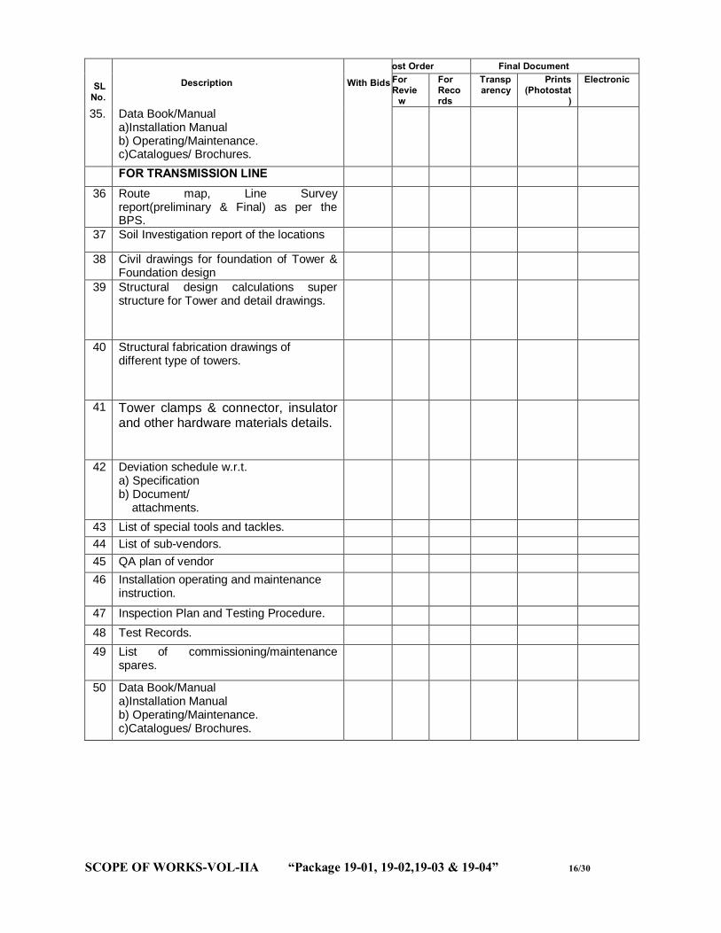
SCOPE OF WORKS-VOL-IIA “Package 19-01, 19-02,19-03 & 19-04” 16/30
SL No.
Description With Bids
Post Order Final Document For Revie
w
For Records
Transparency
Prints (Photostat
)
Electronic
35. Data Book/Manual a)Installation Manual b) Operating/Maintenance. c)Catalogues/ Brochures.
FOR TRANSMISSION LINE
36 Route map, Line Survey report(preliminary & Final) as per the BPS.
37 Soil Investigation report of the locations
38 Civil drawings for foundation of Tower & Foundation design
39 Structural design calculations super structure for Tower and detail drawings.
40 Structural fabrication drawings of different type of towers.
41 Tower clamps & connector, insulator and other hardware materials details.
42 Deviation schedule w.r.t. a) Specification b) Document/ attachments.
43 List of special tools and tackles. 44 List of sub-vendors. 45 QA plan of vendor 46 Installation operating and maintenance
instruction.
47 Inspection Plan and Testing Procedure. 48 Test Records. 49 List of commissioning/maintenance
spares.
50 Data Book/Manual a)Installation Manual b) Operating/Maintenance. c)Catalogues/ Brochures.

SCOPE OF WORKS-VOL-IIA “Package 19-01, 19-02,19-03 & 19-04” 17/30
11. Minimum clearance for substation design shall be as per details given in the table below. Highest system voltage (kV)
Insulation level (kVP)
Switching Impulse Voltage (KVP)
Sectional Clearance (mm)
Minimum clearance Ground Clearance (mm)
Between phase & Ground
Between phases
36KV 170 - 3000 320
320 3700
145KV 650 - 4000 1300
1300 4600
245KV 1050 - 5000 2160 2160 5500

SCOPE OF WORKS-VOL-IIA “Package 19-01, 19-02,19-03 & 19-04” 18/30

SCOPE OF WORKS-VOL-IIA “Package 19-01, 19-02,19-03 & 19-04” 19/30
12. OPTCL adopted standard switch yard structure (weight of the structures are indicative): The bidders may adopt their own type tested design for switchyard structures & transmission line structures with approval from OPTCL. (I) SWITCHYARD TOWER STRUCTURE (Indicative only): A 400 KV SIDE:(Switch yard tower column & beam)
1 COLUMN: 4TA,4TB,4TC,4TD TYPE,- HEIGHT-29 (Additional Peak 5 Mtrs) MTRS, WEIGHT-10 MT
2 BEAM:4GA,4GB TYPE,-LENGTH- 27 MTRS, WEIGHT-4 MT B 220 KV SIDE:(Switch yard tower column & beam)
3. COLUMN: P1S TYPE,- HEIGHT-21.5 MTRS,WEIGHT-4.464MT 4. BEAM:Q1 TYPE,-LENGTH-18 MTRS, WEIGHT-1.473MT
C 132 KV SIDE :(Switch yard tower column & beam)
6. COLUMN: T1S TYPE,- HEIGHT-15 MTRS,-WEIGHT-1.193 MT
7. COLUMN: T4S TYPE,-HEIGHT-11 MTRS,-WEIGHT-0.924 MT
8. BEAM:G1 TYPE,-LENGTH-10.4 MTRS,-WEIGHT-0.613 MT
9. BEAM:G2 TYPE,-LENGTH-14.9875 MTRS,-WEIGHT-0.906 MT
10. BEAM:G1X TYPE,-LENGTH-10.4 MTRS,-WEIGHT-1.370 MT
11. BEAM:G1,2 TYPE,-LENGTH-10.4 MTRS,-WEIGHT-1.25 MT
D 33 KV SIDE:(Switch yard tower column & beam)
1. COLUMN: T8S TYPE,- HEIGHT-10.5 MTRS,WEIGHT- 0.777 MT
2. COLUMN: T9S TYPE,-HEIGHT-7.5 MTRS,WEIGHT - 0.592 MT
3. BEAM:G4 TYPE,-LENGTH-5.5 MTRS,WEIGHT-0.306 MT
4. BEAM:G4X TYPE,-LENGTH-5.5 MTRS,WEIGHT-0.306 MT 5. BEAM:G6 TYPE,-LENGTH- MTRS,WEIGHT-7.25 MT
(II) THE BAY WIDTH OF DIFFERENT VOLTAGE LEVEL ARE AS BELOW (Indicative only) 1. 400 KV SYSTEMS SHALL BE 27 MTRS. 2. 220 KV SYSTEMS SHALL BE 18 MTRS 3. 132 KV SYSTEMS SHALL BE 10.4/13.1MTRS. 4. 33 KV SYSTEMS SHALL BE 5.5 MTRS (III) WEIGHT OF SWITCHYARD EQUIPMENT STRUCTURE: (Indicative only) Sl No.
DESCRIPTION OF EQUIPMENT
220 KV 132 KV 33 KV
1 Isolator 0.725 MT DI:1.16MT SI:0.56 MT
DI:0.71MT SI:0.36 MT
Current Transformer
0.254MT 0.226MT 0.181MT
Voltage transformer
0.254MT 0.246MT 0.134MT
Capacitive voltage transformer
0.254MT 0.246MT
Bus post insulator 0.254MT 0.246MT 0.134MT

SCOPE OF WORKS-VOL-IIA “Package 19-01, 19-02,19-03 & 19-04” 20/30
Surge arrestor 0.254MT 0.226MT 0.181MT Wave trap 0.254MT 0.226MT - NCT - - 0.226MT 13. OPTCL adopted standard Tower structure for transmission line:
The contractor may adopt their own type tested design for transmission line structures/towers with approval from OPTCL.
A. 132 KV Transmission line.(Height 29 Mtrs)(MS Galvanised) (Indicative only): (i) “PA” type: Unit weight: 3.430 MT. (ii) + 3 mtrs: Unit weight: 0.537 MT. (iii) + 6 mtrs: Unit weight: 1.349MT. (iv) “PB” type: Unit weight: 4.973 MT. (v) + 3 mtrs: Unit weight: 1.018 MT. (vi) + 6 mtrs: Unit weight: 2.104 MT. (vii) “PC” type: Unit weight: 6.214 MT. (viii) + 3 mtrs: Unit weight: 1.119 MT. (ix) + 6 mtrs: Unit weight: 2.342 MT. (x) Templates for PA- Unit weight: 0.665 MT (xi) Templates for PB- Unit weight: 0.602 MT (xii) Templates for PC- Unit weight: 1.904 MT
B. 220 KV Transmission line.(Height 35.5 Mtrs) (MS Galvanised) (Indicative only): (i) “OA” type: Unit weight: 4.351 MT. (ii) + 3 mtrs: Unit weight: 0.727 MT. (iii) + 6 mtrs: Unit weight: 1.448 MT. (iv) “OB” type: Unit weight: 7.574 MT. (v) + 3 mtrs: Unit weight: 1.305 MT. (vi) + 6 mtrs: Unit weight: 2.242 MT. (vii) “OC” type: Unit weight: 9.839 MT. (viii) + 3 mtrs: Unit weight: 1.436 MT. (ix) + 6 mtrs: Unit weight: 2.599 MT. (x) +15 mtrs: Unit weight: 6.670 MT (xi) “UR” : Unit weight: 13.585 MT. (xii) “UR” + 3 mtrs type: Unit weight: 17.316 MT. (xiii) “UR” + 6 mtrs type: Unit weight: 4.249 MT. (xiv) Templates for OA- Unit weight: 0.597 MT

SCOPE OF WORKS-VOL-IIA “Package 19-01, 19-02,19-03 & 19-04” 21/30
(xv) Templates for OB- Unit weight: 0.815 MT (xvi) Templates for OC- Unit weight: 1.172 MT (xvii) Templates for UR- Unit weight: 1.509 MT
C. 400 KV Transmission line Tower.(Height 46 Mtrs)(HT Steel in Leg Section,Cross Arm & Main Bracing and other Section MS) (Indicative only):
(I) DA (Normal) Type:( 0 to 2 deg): 7.54869 MT DA(+3 Mtr extn): +1.93856 MT DA(+6 Mtr Extn): +2.74532 MT DA(+9 Mtr Extn): +4.62562 MT (ii) DB Type:( 2 to 15 deg): 13.96342 MT DB(+3 Mtr extn): + 2.44864 MT DB(+6 Mtr Extn): +4.82572 MT DB(+9 Mtr Extn): +9.34636 MT (iii) DC Type:( 15 to 30 deg): 15.78074 MT DC(+3 Mtr extn): +2.90732 MT DC(+6 Mtr Extn): +5.4436 MT DC (+9 Mtr Extn): +9.94816 MT (iv) DD Type:(30 to 60 deg): 22.29494 MT. DD(+3 Mtr extn): +4.11758 MT DD(+6 Mtr Extn): +5.25294 MT DD (+9 Mtr Extn): +7.2021 MT
D. No. of Bolts & Nuts used in each of the Tower(Indicative only):
Type of Tower Normal +3 mtrs +6 mtrs +9 mtrs PA 1602 142 276 PB 1097 273 542 PC 1654 313 592 OA 1147 180 228 OB 1299 236 372 OC 1877 254 402 UR 2283 357 588 DA 1980 524 722 1214 DB 3668 656 1284 2464 DC 4140 786 1442 2608 DD 5844 1080 1388 1912

SCOPE OF WORKS-VOL-IIA “Package 19-01, 19-02,19-03 & 19-04” 22/30
14. Approved Make Of Equipment & Materials to be used in the Sub-station and Transmission lines. The following make of the equipments & materials shall be supplied as per approved vendor list.
VENDOR LIST FOR SUBSTATION AND LINE WORKS OF OPTCL Sl No Description of Equipment or material Name of the Vendor
1 BREAKER
1.1 400 KV Spring-Spring, SF-6, 3150A, 50KA
Siemens/ABB/CGL/AREVA/BHEL
1.2 220 KV Spring-Spring, SF-6, 3150A, 40KA
Siemens/ABB/CGL/AREVA
1.3 132 KV Spring-Spring, SF-6, 3150A, 40KA
Siemens/ABB/CGL/AREVA
1.4 33 KV Spring-Vacuum, 1600A, 25KA Siemens/ABB/CGL/AREVA/BHEL
2 CT
2.1 400 KV ( Live Tank) & 220 KV(Dead / Live Tank)
AREVA/ABB/CGL/BHEL/SIEMENS
2.2 132 KV, (Dead / Live Tank)
AREVA/ABB/CGL/BHEL/VISHAL/TRANSFIELD/ INDIAN TRANSFORMER/VICTRANS/ VIJAYA ELECTRICALS/ MEHRUL ELECTRICAL & MECHANICAL ENGINEERS(P)LTD/KAPCO ELECTRIC (P)LTD
2.3 33 KV, (Dead / Live Tank)
AREVA/ABB/CGL/PRAGATI/VISHAL/TRANSFIELD / INDIAN TRANSFORMER /VICTRANS/ VIJAYA ELECTRICALS/ MEHRUL ELECTRICAL & MECHANICAL ENGINEERS/ KAPCO ELECTRIC (P)LTD
3 CVT
400KV, 220KV & 132KV AREVA/ABB/CGL/BHEL/SIEMENS
4 PT / IVT
4.1 400KV & 220KV AREVA/ABB/CGL/BHEL/SIEMENS
4.2 132KV & 33KV AREVA/ ABB/ CGL/ BHEL/ INDIAN TRANSFORMERS / VIJAYA ELECTRICALS/ VICTRANS/ MEHRUL ELECTRICAL & MECHANICAL ENGINEERS/ KAPCO
5 SURGE ARRESTOR
400KV, 220KV, 132KV & 33KV CGL/OBLUM/ AREVA/ LAMCO/ ELPRO INTERNATIONAL
6 CR PANEL
400KV, 220KV, 132KV & 33KV ABB/SIEMENS/AREVA/OTHER MANUFACTURERS USING RELAYS OF SIEMENS/AREVA/ABB/ SEL/ GE
7 ISOLATORS (I) 400KV ABB/SIEMENS/SWITHGEAR&STRUCTURALS/GR POWER/AREVA/CGL
(II) 220KV, 132KV & 33KV ABB/SIEMENS/SWITHGEAR&STRUCTURALS/GR POWER/AREVA/CGL/ J.D Electrical Ltd/ PR ENGINEERING

SCOPE OF WORKS-VOL-IIA “Package 19-01, 19-02,19-03 & 19-04” 23/30
8 HARDWARE FITTINGS
8.1 400KV RASTRIYA UDHYOG/ ERITECH/ IAC/ EMI, KRSNA TRANSMISSION HARDWARE MFG PVT LTD/ INDUSTRIAL SPARE PRODUCTS. SUPREME & CO. PVT. LTD
8.2 220KV, 132KV & 33KV RASTRIYAUDHYOG/ERITECH/IAC/EMI/ELECTRO TECH AND TRANSTECH, KRSNA TRANSMISSION HARDWARE MFG PVT LTD. JAINCO TRANSMISSION LTD, A.K.POWER INDUSTRIES PVT LTD, INDUSTRIAL SPARE PRODUCTS/ SWAMIJI TRANSMISSION PVT. LTD/NIKE ENERGY MANUFACTURING PVT.LTD
9 CONDUCTOR APAR, GPIL, ERITECH, STERLITE, VIJAYA/ LUMINO/CABCON/TIRUPATI/ TERACOM/ KJV ALLOY
10 EARTHWIRE BHARAT WIRE ROPES/UIC WIRES/USHA MARTIN /GK WIRE, BEDMUTHA INDUSTRIES
11 DISC INSULATORS/SOLID CORE POST INSULATORS
BHEL/WS/MODERN INSULATOR/ADITYA BIRLA INSULATORS/ SRAVANA, M/S INSULATORS & ELECTRICALS COMPANY, MANDEEP
12 LONG ROD INSULATOR MODERN INSULATORS
13 COMPOSITE POLYMER INSULATOR GOLDSTONE INFRATECH LTD/ DECAN ENTERPRISERS/ ADITY BIRLA INSULATOR
14 TOWER & STRUCTURES FOR LINE AND SUBSTATION AND FOUNDATION BOLT (SAIL/TATA/RINL STEEL TO BE USED)
KEC/RPG/JYOTI /L&T/EMC/KALPATARU/ NEXO/ UTKAL GALVANIZER/IVRCL INFRASTRUCTURES &PROJECTS LTD, NAGPUR/ UNIQUE STRUCTURES&TOWERS LTD BHILAI/TECHNO ENGINEERING &CO LTD NEW DELHI/UNISTAR GALVANISERS & FABRICATORS(P) LTD JAMSEDPUR/NEW MODERN TECHNO MECH PVT. LTD, BARIPADA / GLOBAL GALVANISER, KHURDA/ AGARWAL STEEL STRUCTURES (INDIA) PVT LTD, HYDERABAD/ SRI ASHUTOS ENGINEERING, RAIPUR/ ASTER PVT LIMITED, HYDERABAD/SHREEM ELECTRICALS PVT LIMITED, BANGALORE./ A.K.POWER INDUSTRIES/ VIJAY TRANSMISSION /GURUNANAK OVERSEAS/ SOLUX GALFAB /G.S.ENGINEERS
15 PVC INSULATED POWER AND CONTRAL CABLES
NICCO/GLOSTER/CCI/KEI/CRYSTAL/POLYCAB/ GPIL/ FINOLEX/UNIVERSAL/M/S HAVELLS INDIA LTD/ KEC INTERNATIONAL LTD /DAKSHA INDUSTRIES /V-GUARD/ SCOT INNOVATION/ GEMSCAB/MOHTA ELECTRO SYSTEM(MESCAB)
16 132KV GRADE CABLE KEI INDUSTRIES LTD/ CABLE CORPORATION OF INDIA/ UNIVERSAL CABLE
17 HF COAXIAL CABLES ALPHA COMMUNICATION, DELHI/DELTON CABLES, NEW DELHI
18 STATION TRANSFORMER (BEE STANDARD)
AREVA/ALFA/TESLA/OTPL

SCOPE OF WORKS-VOL-IIA “Package 19-01, 19-02,19-03 & 19-04” 24/30
19 FIRE FIGHTING EQUIPMENT MINIMAX/CEASE FIRE/ M/S KANADIA FYR FYTER PVT LTD./ASKA EQUIPMENTS LIMITED
20 LIGHTING FIXTURES PHILPS/CGL/BAJAJ/HAVELS,AVNI SOLUTIONS PVT LTD.OTHER MAKE LED LIGHTING AS PER BEE STANDARD
21 CEMENT OPC GRADE -43 ACC/ULTRA TECH/KONARK/LAFARGE
22 STEEL SAIL/TATA/RINL& STEELS OF OTHER MAKE TO BE APPROVED BY OPTCL AS & WHEN REQUIRED.
23 GI PIPE TATA/JINDAL
24 AIR CONDITIONER HITACHI/CARRIER/BLUE STAR/VOLTAS/LG
25 PVC WIRES L&T/FINOLEX/ANCHOR/KDK/HAVELLS
26 SWITCHES ANCHOR/ABB/CONA/INDO ASIAN/HAVELS
27 MCB L&T/ABB/SIEMENS/MDS/ HAVELLS/INDO ASIAN
28 ACB/MCCB L&T/SIEMENS/MERLIN GERIN
29 ACDB/DCDB/BMK/CONSOLE BOX
MAKTEL SYSTEM (VADODARA) /SARVANA (CHENAI)/ TECHNOCRAT (CUTTACK)/UNITED ENGINEERS /BOSE ENGINEERING (INDIA) / ALFA AUTOMATION/ AMARA RAJA/ CHHABI ELECTRICAL
30 CLAMPS AND CONNECTORS ELECTROMECH TRANSTECH/ RASTRA UDYOG /TYCO/IAC /ASWINI KUMAR & CO.
31 GI BOLTS & NUTS NEXO/ GKW/ ASP/ MAHESWARI (P) FASTENERS & BRIGHT PVT. LTD
32 220V PLANATE BATTERY EXIDE
33 48V VRLA BATTERY EXIDE /AMARRAJA
34 220V DC BATTERY CHARGER STATCON POWER CONTROLS/ AMARRAJA/ CHLORIDE INDIA (FORMERLY CALDYNE)
35 48V DC BATTERY CHARGER SIGNOTRON(INDIA)/ CHLORIDE INDIA (FORMERLY CALDYNE)/ STATCON POWER CONTROLS./ AUTOMATIC ELECTRIC/ AMARRAJA
36 WAVE TRAP AREVA/ ABB/ BPL
37 DIGITAL PLCC WITH PROTECTION COUPLER, FSK MODEM FOR VFT
AREVA/ ABB/ SIEMENS/ MAKE CONFIRMING TO IEC STANDARD & COMPATIBLE WITH OPTCL SYSTEM
38 EPBX BPL/SIEMENS/PUNCOM
39 RTU ABB/ SIEMENS/ AREVA/ CHEMTROL MAKE CONFIRMING TO IEC 870-5-101 PROTOCOL & COMPATIBLE WITH OPTCL SYSTEM
40 220/132KV LINE TRAP AREVA/ABB/CGL/BPL/GYRO
41 MEASURING INSTRUMENTS FOR TELECOM
ELECTRONICA/FLUKE/PHILIPS
Sl No Description of Equipment or material Name of the Vendor
42 SPILTTER FOR CFE ALSTOM/CEGELAC
43 STALLION MODULE FOR CFE STALLION TECHNOLOGIES INC. / ANY OTHER
SCOPE OF WORKS-VOL-IIA “Package 19-01, 19-02,19-03 & 19-04” 25/30
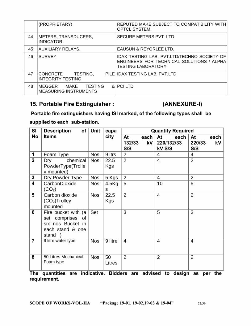
(PROPRIETARY) REPUTED MAKE SUBJECT TO COMPATIBILITY WITH OPTCL SYSTEM.
44 METERS, TRANSDUCERS, INDICATOR.
SECURE METERS PVT LTD
45 AUXILIARY RELAYS. EAUSUN & REYORLEE LTD.
46 SURVEY IDAX TESTING LAB. PVT.LTD/TECHNO SOCIETY OF ENGINEERS FOR TECHNICAL SOLUTIONS / ALPHA TESTING LABORATORY
47 CONCRETE TESTING, PILE INTEGRITY TESTING
IDAX TESTING LAB. PVT.LTD
48 MEGGER MAKE TESTING & MEASURING INSTRUMENTS
PCI LTD
15. Portable Fire Extinguisher : (ANNEXURE-I) Portable fire extinguishers having ISI marked, of the following types shall be supplied to each sub-station.
Sl No
Description of Items
Unit capacity
Quantity Required At each 132/33 kV S/S
At each 220/132/33 kV S/S
At each 220/33 kV S/S
1 Foam Type Nos 9 ltrs 2 4 4 2 Dry chemical
PowderType(Trolley mounted)
Nos 22.5 Kgs
2 4 2
3 Dry Powder Type Nos 5 Kgs 2 4 2 4 CarbonDioxide
(CO2) Nos 4.5Kg
s 5 10 5
5 Carbon dioxide (CO2)Trolley mounted
Nos 22.5 Kgs
2 4 2
6 Fire bucket with (a set comprises of six nos Bucket in each stand & one stand )
Set 3 5 3
7 9 litre water type
Nos 9 litre 4 4 4
8 50 Litres Mechanical Foam type
Nos 50 Litres
2 2 2
The quantities are indicative. Bidders are advised to design as per the requirement.

SCOPE OF WORKS-VOL-IIA “Package 19-01, 19-02,19-03 & 19-04” 26/30
16. Maintenance & Testing Equipment: (ANNEXURE-II) Maintenance & testing equipment shall be supplied & installed for each substation as per the list given below. These equipment shall be of international repute & must be under use presently in any CTU/STU. Performance certificate for one year (2011-12) from the CTU/STU must be accompanied during approval of the product. Sl. No
Description of Items Unit Quantity Required At each 132/33 KV S/S
At each 220/132/33 KV S/S
At each 220/33 KV S/S
1. 160 kv transformer oil breakdown voltage test set
Nos 1 1 1
2. Insulation resistance tester (megger)
Nos 1 1 1
3. Oil sampling bottle Nos 4 4 4 4. SF6 gas leak detector Nos 1 1 1 5. LCD, digital multimeter Nos 2 2 2 6. Analogue Multimeter(features
same as digital multimeter) Nos 1 2 1
7. LCD, clamp on meter Nos 2 2 2 8. Digital earth tester Nos 1 1 1 9. Discharge rod as per standard for
carrying out the switch yard maintenance work
Nos 6 6 6
10. Rubber gloves of operation of isolators and earth switch
Pairs
2 2 2
11. Relay tools kit Sets 1 1 1 12. Portable emergency light Nos 4 4 4 13. Latest version desktop PC of
reputed make with all its accessories including CPU, Monitor, UPS and having all latest loaded software and also its back up in shape of CD and separate pen drive . Suitable for loading of software as recommended by the relay manufacturer. It includes supply of one no portable laser printer of reputed make. Make of PC and printer: HP/DELL
Set 1 1 1
** The multimeters (both digital and analogue), clamp on meters, earth tester shall of “Motwane/Megger/Inter National repute” make. Prior approvals of OPTCL for all the testing equipments are to be taken. *** Insulation resistance tester shall of M/S Megger .
SCOPE OF WORKS-VOL-IIA “Package 19-01, 19-02,19-03 & 19-04” 27/30
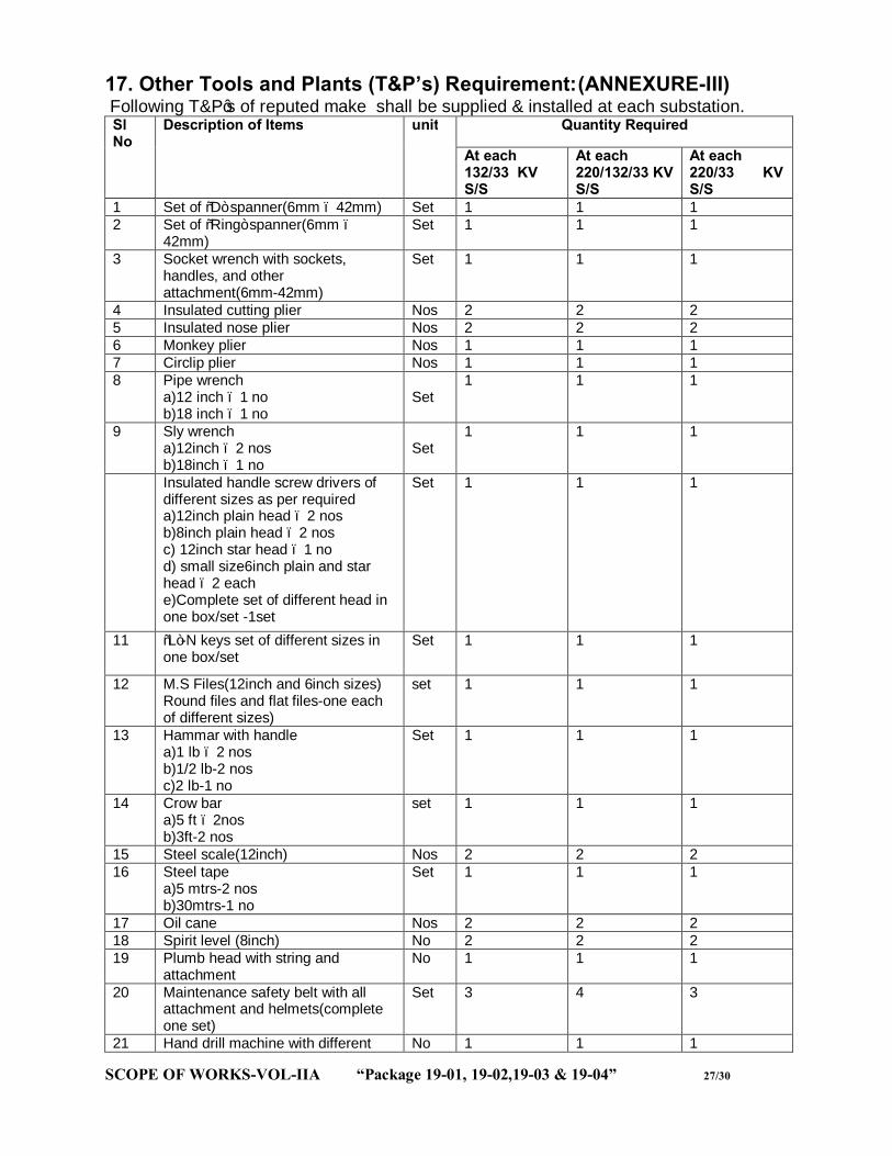
17. Other Tools and Plants (T&P’s) Requirement: (ANNEXURE-III) Following T&P’s of reputed make shall be supplied & installed at each substation. Sl No
Description of Items unit Quantity Required
At each 132/33 KV S/S
At each 220/132/33 KV S/S
At each 220/33 KV S/S
1 Set of “D” spanner(6mm – 42mm) Set 1 1 1 2 Set of “Ring” spanner(6mm –
42mm) Set 1 1 1
3 Socket wrench with sockets, handles, and other attachment(6mm-42mm)
Set 1 1 1
4 Insulated cutting plier Nos 2 2 2 5 Insulated nose plier Nos 2 2 2 6 Monkey plier Nos 1 1 1 7 Circlip plier Nos 1 1 1 8 Pipe wrench
a)12 inch – 1 no b)18 inch – 1 no
Set
1 1 1
9 Sly wrench a)12inch – 2 nos b)18inch – 1 no
Set
1 1 1
Insulated handle screw drivers of different sizes as per required a)12inch plain head – 2 nos b)8inch plain head – 2 nos c) 12inch star head – 1 no d) small size6inch plain and star head – 2 each e)Complete set of different head in one box/set -1set
Set 1 1 1
11 “L”-N keys set of different sizes in one box/set
Set 1 1 1
12 M.S Files(12inch and 6inch sizes) Round files and flat files-one each of different sizes)
set 1 1 1
13 Hammar with handle a)1 lb – 2 nos b)1/2 lb-2 nos c)2 lb-1 no
Set 1 1 1
14 Crow bar a)5 ft – 2nos b)3ft-2 nos
set 1 1 1
15 Steel scale(12inch) Nos 2 2 2 16 Steel tape
a)5 mtrs-2 nos b)30mtrs-1 no
Set 1 1 1
17 Oil cane Nos 2 2 2 18 Spirit level (8inch) No 2 2 2 19 Plumb head with string and
attachment No 1 1 1
20 Maintenance safety belt with all attachment and helmets(complete one set)
Set 3 4 3
21 Hand drill machine with different No 1 1 1
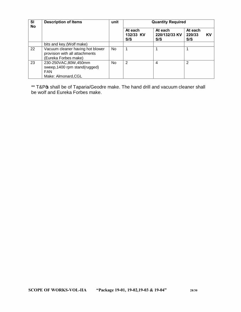
SCOPE OF WORKS-VOL-IIA “Package 19-01, 19-02,19-03 & 19-04” 28/30
Sl No
Description of Items unit Quantity Required
At each 132/33 KV S/S
At each 220/132/33 KV S/S
At each 220/33 KV S/S
bits and key.(Wolf make) 22 Vacuum cleaner having hot blower
provision with all attachments (Eureka Forbes make)
No 1 1 1
23 230-250VAC,80W,450mm sweep,1400 rpm stand(rugged) FAN Make: Almonard,CGL
No 2 4 2
** T&P’s shall be of Taparia/Geodre make. The hand drill and vacuum cleaner shall be wolf and Eureka Forbes make.

SCOPE OF WORKS-VOL-IIA “Package 19-01, 19-02,19-03 & 19-04” 29/30
18. Office Furniture: (ANNEXURE-IV) Office furniture shall be supplied & installed at each substation as per the list given below. All the furniture shall be of Godrej make. Before supply of the furniture to the sub-station, approval from OPTCL is required. Details of the scope of supply are as indicated below.
Sl No Description of Items unit Quantity Required At each 132/33 KV S/S
At each 220/132/33 KV S/S
At each 220/33 KV S/S
1 5ftX3ft executive table with drawer both sides
Nos 5 6 5
2 3ftX2&1/2ft Table with one side drawer
Nos 7 8 7
3 Computer table suitable keeping monitor, CPU,UPS and printer with two nos revolving arm chair suitable for computer use.
Set 1 1 1
4 Executive revolving ,adjustable (height) chairs with arm
Nos 5 6 5
5 Cushion fixed “S” type steel chairs with arm
Nos 18 24 18
6 6ftX3ft conference table
Nos 1 1 1
7 Cushion arm steel chairs for conference table purpose.
Nos 6 8 6
8 6ft height steel almirah (only with selves) for keeping records and other valuable items.
Nos 4 6 4
9 6ft height steel almirah with glass doors for library purpose
Nos 2 2 2
10 6ft height (having minimum 6 lockers facility) steel cupboard with locking arrangement.
Nos 2 2 2
11 4ft steel rack (minimum three selves) for keeping the files and other items.
Nos 8 10 8

SCOPE OF WORKS-VOL-IIA “Package 19-01, 19-02,19-03 & 19-04” 30/30
19. PORTABLE ALUMINIUM LADDER EXTENDABLE TYPE OF 3m+ 3mTO BE USED FOR MAINTENANCE OF EQUIPMENT INSIDE SWITCH YARD. Heavy duty Two fold with sliding feature aluminum ladder to be used for the maintenance work equipment in the switch yard( 220 KV,132 KV & 33 KV: Breaker, CT, CVT, Isolators etc) & also street lighting maintenance. Each fold will be of minimum height of 3 Mtrs and should have better locking arrangement between each folds for better rigidity. 20. PEDESTAL MOUNTED WHEEL FITTED DERRICK FOR LIFTING/ LOWERING OF MATERIALS UP TO 1.5 TON CAPACITY. Heavy duty Pedestal mounted wheel fitted derrick for lifting/ lowering of materials up to 1.5 ton capacity to be used for the maintenance work equipment in the switch yard (220 KV,132 KV & 33 KV: Breaker, CT, CVT, Isolators etc) & also other maintenance works. The height of the derrick will be suitable for lowering of the top pole of the circuit breaker up to 220 KV and other equipments upto 220 KV.
END OF VOLUME-IIA (SCOPE OF WORK)