ODEON RANGE - ponsel-web.com · The ODEON portable unit can measure both physico-chemical and...
90
1 PONSEL MESURE-Groupe AQUALABO 35 Rue Michel MARION – 56850 CAUDAN Tel.: 02 97 89 25 30 – Fax: 02 97 76 55 72 www.ponsel.fr, email: [email protected] User manual ODEON PHOTOPOD Last update: April 2014 Version : 5.0.1 ODEON RANGE Portable field equipment for measuring and recording water quality parameters for monitoring purposes
Transcript of ODEON RANGE - ponsel-web.com · The ODEON portable unit can measure both physico-chemical and...
1
PONSEL MESURE-Groupe AQUALABO 35 Rue Michel MARION – 56850 CAUDAN Tel.: 02 97 89 25 30 – Fax: 02 97 76 55 72 www.ponsel.fr, email: [email protected]
User manual ODEON PHOTOPOD Last update: April 2014 Version : 5.0.1
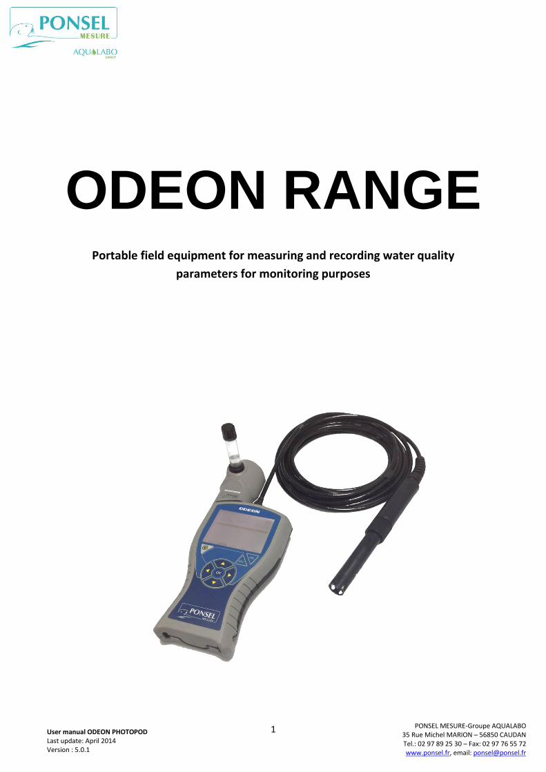
ODEON RANGE
Portable field equipment for measuring and recording water quality
parameters for monitoring purposes

2
PONSEL MESURE-Groupe AQUALABO 35 Rue Michel MARION – 56850 CAUDAN Tel.: 02 97 89 25 30 – Fax: 02 97 76 55 72 www.ponsel.fr, email: [email protected]
User manual ODEON PHOTOPOD Last update: April 2014 Version : 5.0.1
CONTENTS
1. CAUTIONS .................................................................................................................................................... 4
2. GENERAL POINTS .......................................................................................................................................... 4
2.1 PRODUCT OVERVIEW .......................................................................................................................................... 4
2.2 – MAIN FUNCTIONS OF THE ODEON UNIT ............................................................................................................. 4
2.3 – ADDITIONAL FEATURES ..................................................................................................................................... 5
3 . TECHNICAL CHARACTERISTICS ..................................................................................................................... 6
3.1 - DESCRIPTION OF THE ODEON UNIT .................................................................................................................... 6
3.2 – COMPONENTS ................................................................................................................................................ 7
3.3 - DESCRIPTION OF THE SENSORS ............................................................................................................................ 8
3.3.1 Oxygen/temperature sensor – PODOA-PODOB................................................................................... 8
3.3.2- Turbidity/temperature sensor – PNEPA-PNEPB ............................................................................... 10
3.3.3- Conductivity/temperature sensor – PC4EA-PC4EB ........................................................................... 12
3.3.4- pH/Redox/temperature sensor – PPHRA-PPHRB ............................................................................. 14
3.3.5- CTZN inductive conductivity sensor - PCTZA. .................................................................................... 17
3.3.6 - Description of the PHOTOPOD ......................................................................................................... 19
4. USING THE ODEON ..................................................................................................................................... 20
4.1 – POWER SUPPLY ............................................................................................................................................. 21
4.1.1-Restrictions on battery type ............................................................................................................... 21
4.1.2-Changing the batteries ....................................................................................................................... 21
4.1.3- Using rechargeable batteries ............................................................................................................ 21
4.1.4- Prolonged storage or use .................................................................................................................. 21
4.2 – CONNECTING SENSORS AND THE PHOTOPOD. .................................................................................................. 22
4.2.1-Connecting digital sensors. ................................................................................................................ 22
4.2.2-Connecting the PHOTOPOD. .............................................................................................................. 22
4.3 – GENERAL FUNCTIONS OF THE ODEON. ............................................................................................................. 23
4.3.1 On/Off and standby mode. ................................................................................................................ 23
4.3.2 Navigation keypad. ............................................................................................................................ 23
4.3.3- Start-up screen .................................................................................................................................. 24
4.4. USING THE UNIT WITH DIGITAL PHYSICO-CHEMICAL SENSORS. .................................................................................. 25
4.4.1- SCAN function .................................................................................................................................... 25
4.4.2- Main screen: MEASURE ..................................................................................................................... 26
4.4.3.General functions ............................................................................................................................... 28 a- LANGUAGE selection. ............................................................................................................................................ 28 b. Configuring the DATE and TIME ............................................................................................................................. 29 c. Configuring a user .................................................................................................................................................. 29 d. ADDRESSING menu ................................................................................................................................................ 31 e. PREFERENCES MENU.............................................................................................................................................. 34
4.4.4- SELECTING the parameters displayed ................................................................................................ 35
4.4.5- RECORDING measurements ............................................................................................................... 37
4.4.6- Viewing the RESULTS .......................................................................................................................... 43
4.4.7- Calibrating the parameters. ............................................................................................................... 44 a. Adjusting the ambient atmospheric pressure sensor ........................................................................................... 45 b. Defining a salinity value in order to correct the measurement of the dissolved oxygen:...................................... 45 c. Defining a calibration frequency for each parameter: ........................................................................................... 46 d. Calibrating: ............................................................................................................................................................. 46
d.1- Temperature calibration: ............................................................................................................................... 47 d.2- Oxygen level calibration: ............................................................................................................................... 48
3
PONSEL MESURE-Groupe AQUALABO 35 Rue Michel MARION – 56850 CAUDAN Tel.: 02 97 89 25 30 – Fax: 02 97 76 55 72 www.ponsel.fr, email: [email protected]
User manual ODEON PHOTOPOD Last update: April 2014 Version : 5.0.1
d.3- pH calibration ................................................................................................................................................ 51 d.4- Redox calibration ........................................................................................................................................... 53 d.5- Calibrating the 4-electrode conductivity sensor (C4EN) ................................................................................ 54 d.6- Calibrating the inductive conductivity sensor (CTZN) .................................................................................... 56 d.8- Turbidity calibration (in mg/L) ....................................................................................................................... 59
e. Calibration history .................................................................................................................................................. 62 f. Using the factory settings. ...................................................................................................................................... 63
4.5. HOW TO USE THE PHOTOPOD PHOTOMETER. .................................................................................................... 64
4.5.1- Photometer reagents: ........................................................................................................................ 64
4.5.2- Preparing the samples:....................................................................................................................... 64
4.5.3- Opening the Photometer menu: ......................................................................................................... 65
4.5.4- Photopod screen ................................................................................................................................. 65 a- Disconnecting the PHOTOPOD............................................................................................................................... 66 b- Returning to SENSOR operating mode .................................................................................................................. 66
4.5.5- Selecting an analysis method. ............................................................................................................ 66
4.5.6- Photometric analysis. ......................................................................................................................... 67 a- Performing a blank measurement. ........................................................................................................................ 67 b- Measuring the sample ........................................................................................................................................... 68
4.5.7- Main Menu of the PHOTOPOD. .......................................................................................................... 69
4.6. LIST OF ANALYSIS METHODS FOR THE PHOTOPOD. ................................................................................... 70
5. ODEON VIEWER APPLICATION .................................................................................................................... 73
5.1 INSTALLING FROM THE ODEON VIEWER DVD. ..................................................................................................... 73
5.1.1 Installing. ............................................................................................................................................. 73
5.1.2 Using the ODEON Viewer application. ................................................................................................. 73 a. Accessing the configuration of the ODEON unit .................................................................................................... 73 b. Creating a Study. .................................................................................................................................................... 73 c. Downloading data .................................................................................................................................................. 75 d. Importing data downloaded using WinTEK Viewer ............................................................................................... 76 e. Data processing: displaying in chart form .............................................................................................................. 78
e.1: Zoom function ................................................................................................................................................ 78 e.2 Configuring the cursor. ................................................................................................................................... 79 e.3 Chart wizard. ................................................................................................................................................... 80 e.4 Preview menu ................................................................................................................................................. 80
f. Data processing: displaying in grid form ................................................................................................................. 81 5.1.3 Uninstalling. ........................................................................................................................................ 82
5.2 INSTALLING THE PONSEL UPDATER APPLICATION. .................................................................................................. 82
5.2.1 Installing from the DVD. ...................................................................................................................... 82
5.2.2 Loading new software and language files into ODEON. ...................................................................... 82
5.2.3 Uninstalling. ........................................................................................................................................ 83
6. SENSORS, ACCESSORIES, CONSUMABLES ................................................................................................... 84
6.1- SENSOR MAINTENANCE. ................................................................................................................................... 84
6.1.1 OPTOD sensor maintenance. ............................................................................................................... 84
6.1.2 NTU sensor maintenance. ................................................................................................................... 85
6.1.3 PHEHT sensor maintenance. ................................................................................................................ 86
6.1.4 C4E sensor maintenance. .................................................................................................................... 87
6.2- DIGITAL SENSORS. ........................................................................................................................................... 88
6.3- ODEON ACCESSORIES – DIGITAL SENSORS .......................................................................................................... 88
6.4- CONSUMABLES FOR PHYSICO-CHEMICAL PART. ..................................................................................................... 89
6.5 PHOTOPOD ACCESSORIES. .............................................................................................................................. 89
4
PONSEL MESURE-Groupe AQUALABO 35 Rue Michel MARION – 56850 CAUDAN Tel.: 02 97 89 25 30 – Fax: 02 97 76 55 72 www.ponsel.fr, email: [email protected]
User manual ODEON PHOTOPOD Last update: April 2014 Version : 5.0.1
1. CAUTIONS
Users of the ODEON range of portable field equipment should read and understand this document in its entirety. Failure to comply with the instructions given in this user guide could cause irreparable damage to the equipment (ODEON, digital sensor and PHOTOPOD). This equipment must only be used under the conditions described in this user guide. Use under any other conditions might result in the malfunction of the ODEON-Sensor/PHOTOPOD measurement chain.
2. GENERAL POINTS
2.1 Product overview
The ODEON range of measuring and data logging equipment can be used in conjunction with one or more PONSEL MESURE digital sensors to measure the following parameters:
- Temperature, - Dissolved oxygen as % saturation, in mg/L and/or ppm, - Turbidity in NTU, FNU or mg/L, - Conductivity (compensated at 25°C), salinity and TDS-KCl, - Induction conductivity (compensated at 25°C), salinity, non-compensated conductivity - pH, - Redox.
The ODEON unit can also be combined with the PHOTOPOD to operate as a digital field photometer.
In total, the various versions of the PHOTOPOD can measure more than 50 parameters, including: NH4+, NO3-, PO4, COD, NO2-, Ptotal, SO42-, Turbidity, Fe, Cu, Mn, Cl2, CN-, ClO2, TH, TA, TAC, N2H4, DEHA, Fe, Br2, Cu, Mn, Mo, SiO2, Zn, Benzotriazole, phosphonates…
Several versions of the ODEON are available:
a)- ODEON CLASSIC: connects to and recognizes a single, specific sensor (oxygen/temperature;
turbidity/temperature; conductivity/salinity/temperature or pH/Redox/temperature).
a)- ODEON OPEN: recognizes all sensors:
- Oxygen/temperature, - Turbidity/temperature, - Conductivity/salinity/TDS/temperature, - pH/Redox/temperature. and the PHOTOPOD.
The ODEON OPEN is available in two versions:
- a single sensor connection: OPEN ONE
- two connectors for simultaneous measurement with two sensors: OPEN X.
2.2 – Main functions of the ODEON unit
The ODEON portable unit can measure both physico-chemical and photometric parameters.
a)- Automatic recognition of the type of sensor connected, and its serial number.
The calibration coefficients associated with the parameters measured by the sensor, and the historical data from calibrations performed previously, are stored within the sensor and are instantly available to ODEON.
The default parameters for each type of sensor are measured and displayed instantaneously by ODEON.
5
PONSEL MESURE-Groupe AQUALABO 35 Rue Michel MARION – 56850 CAUDAN Tel.: 02 97 89 25 30 – Fax: 02 97 76 55 72 www.ponsel.fr, email: [email protected]
User manual ODEON PHOTOPOD Last update: April 2014 Version : 5.0.1
Automatic recognition of the PHOTOPOD, and of its version and serial No.
b)- Automatic refreshing of the measured value for all the selected parameters.
c)- Operation in photometer mode, with selection of the analysis method (including performing blank measurements).
d)- Three data logging modes:
- Snapshot recording mode: saves the value of one of the active parameters at the instant when a keypad command is pressed,
- Automatic recording mode, started manually when a keypad command is pressed,
- Automatic recording mode, programmed by setting the start and end date and time of the measurement campaign.
The saved data is managed by creating a file named by the user (location of the measurement campaign, sample name, etc.).
e)- Each measurement saved in a specific file can be viewed via the RESULT menu
either by scrolling through the data or by selecting the measurement number.
f)- Valuable traceability feature: the user’s identity can be specified. This information is added to the saved data, and notably to the historical data for calibration operations.
g)- The unit switches to standby mode automatically to increase its autonomy.
2.3 – Additional features
a)- High level of equipment protection: IP67 (waterproof) guaranteed when new, prior to any user intervention on the unit (e.g. to replace the batteries) b)- The equipment operates autonomously, powered by four AA alkaline batteries or by 4 AA NiMH rechargeable batteries (provided as an option, with charger cable) or by an external 12V power source (external power supply cable available as an option). c)- Saved data can be retrieved from the device (via a USB link) and viewed on a PC after installing the proprietary software.
6
PONSEL MESURE-Groupe AQUALABO 35 Rue Michel MARION – 56850 CAUDAN Tel.: 02 97 89 25 30 – Fax: 02 97 76 55 72 www.ponsel.fr, email: [email protected]
User manual ODEON PHOTOPOD Last update: April 2014 Version : 5.0.1
3 . TECHNICAL CHARACTERISTICS
3.1 - Description of the ODEON unit
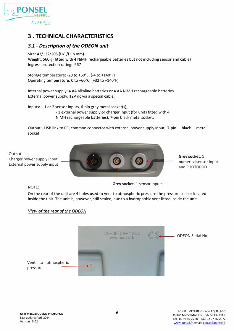
Size: 43/122/205 (H/L/D in mm) Weight: 560 g (fitted with 4 NiMH rechargeable batteries but not including sensor and cable) Ingress protection rating: IP67 Storage temperature: -20 to +60°C. (-4 to +140°F) Operating temperature: 0 to +60°C. (+32 to +140°F) Internal power supply: 4 AA alkaline batteries or 4 AA NiMH rechargeable batteries External power supply: 12V dc via a special cable. Inputs: - 1 or 2 sensor inputs, 6-pin grey metal socket(s), - 1 external power supply or charger input (for units fitted with 4 NiMH rechargeable batteries), 7-pin black metal socket. Output: - USB link to PC, common connector with external power supply input, 7-pin black metal socket.
NOTE:
On the rear of the unit are 4 holes used to vent to atmospheric pressure the pressure sensor located inside the unit. The unit is, however, still sealed, due to a hydrophobic vent fitted inside the unit.
View of the rear of the ODEON
Grey socket, 1 numericalsensor input and PHOTOPOD
Output Charger power supply input External power supply input
Vent to atmospheric pressure
ODEON Serial No.
Grey socket, 1 sensor inputs
7
PONSEL MESURE-Groupe AQUALABO 35 Rue Michel MARION – 56850 CAUDAN Tel.: 02 97 89 25 30 – Fax: 02 97 76 55 72 www.ponsel.fr, email: [email protected]
User manual ODEON PHOTOPOD Last update: April 2014 Version : 5.0.1
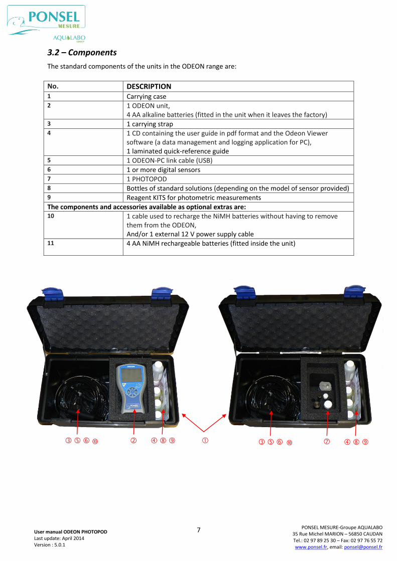
3.2 – Components
The standard components of the units in the ODEON range are:
No. DESCRIPTION 1 Carrying case 2 1 ODEON unit,
4 AA alkaline batteries (fitted in the unit when it leaves the factory) 3 1 carrying strap 4 1 CD containing the user guide in pdf format and the Odeon Viewer
software (a data management and logging application for PC), 1 laminated quick-reference guide
5 1 ODEON-PC link cable (USB) 6 1 or more digital sensors 7 1 PHOTOPOD 8 Bottles of standard solutions (depending on the model of sensor provided) 9 Reagent KITS for photometric measurements
The components and accessories available as optional extras are: 10 1 cable used to recharge the NiMH batteries without having to remove
them from the ODEON, And/or 1 external 12 V power supply cable
11 4 AA NiMH rechargeable batteries (fitted inside the unit)
8
PONSEL MESURE-Groupe AQUALABO 35 Rue Michel MARION – 56850 CAUDAN Tel.: 02 97 89 25 30 – Fax: 02 97 76 55 72 www.ponsel.fr, email: [email protected]
User manual ODEON PHOTOPOD Last update: April 2014 Version : 5.0.1
3.3 - Description of the sensors
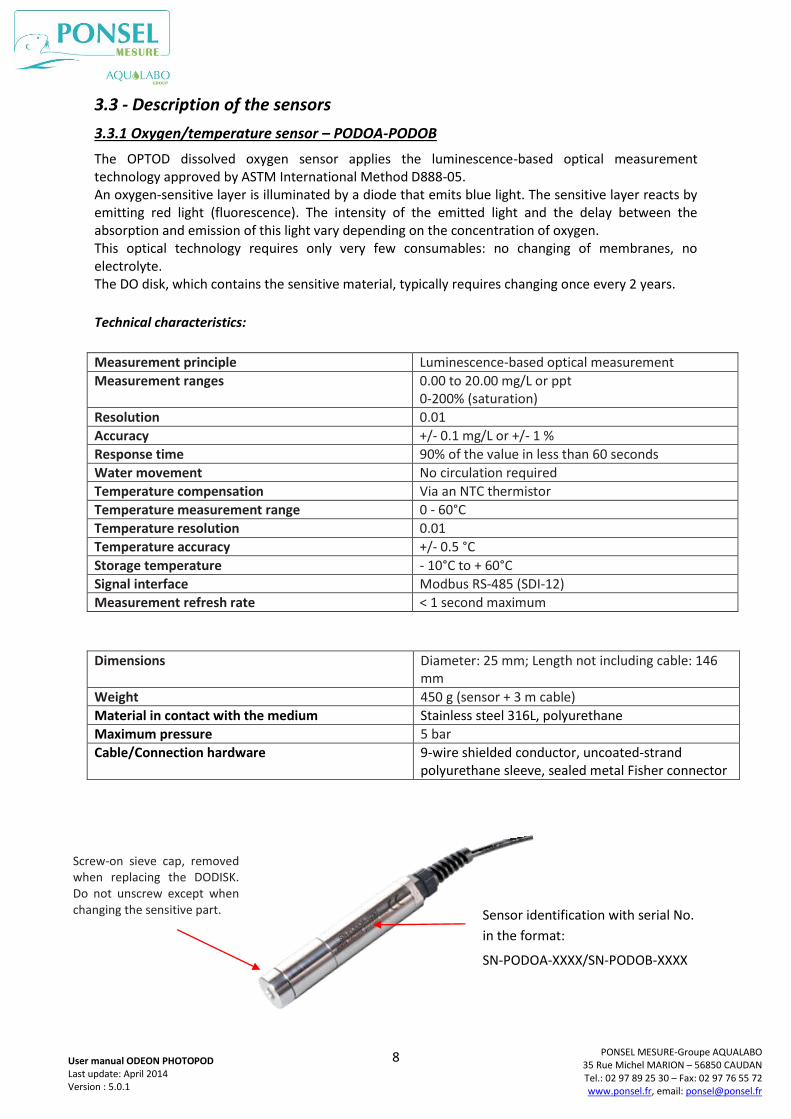
3.3.1 Oxygen/temperature sensor – PODOA-PODOB
The OPTOD dissolved oxygen sensor applies the luminescence-based optical measurement technology approved by ASTM International Method D888-05. An oxygen-sensitive layer is illuminated by a diode that emits blue light. The sensitive layer reacts by emitting red light (fluorescence). The intensity of the emitted light and the delay between the absorption and emission of this light vary depending on the concentration of oxygen. This optical technology requires only very few consumables: no changing of membranes, no electrolyte. The DO disk, which contains the sensitive material, typically requires changing once every 2 years.
Technical characteristics:
Measurement principle Luminescence-based optical measurement
Measurement ranges 0.00 to 20.00 mg/L or ppt 0-200% (saturation)
Resolution 0.01
Accuracy +/- 0.1 mg/L or +/- 1 %
Response time 90% of the value in less than 60 seconds
Water movement No circulation required
Temperature compensation Via an NTC thermistor
Temperature measurement range 0 - 60°C
Temperature resolution 0.01
Temperature accuracy +/- 0.5 °C
Storage temperature - 10°C to + 60°C
Signal interface Modbus RS-485 (SDI-12)
Measurement refresh rate < 1 second maximum
Dimensions Diameter: 25 mm; Length not including cable: 146
mm
Weight 450 g (sensor + 3 m cable)
Material in contact with the medium Stainless steel 316L, polyurethane
Maximum pressure 5 bar
Cable/Connection hardware 9-wire shielded conductor, uncoated-strand polyurethane sleeve, sealed metal Fisher connector
Screw-on sieve cap, removed when replacing the DODISK. Do not unscrew except when changing the sensitive part.
Sensor identification with serial No.
in the format:
SN-PODOA-XXXX/SN-PODOB-XXXX
9
PONSEL MESURE-Groupe AQUALABO 35 Rue Michel MARION – 56850 CAUDAN Tel.: 02 97 89 25 30 – Fax: 02 97 76 55 72 www.ponsel.fr, email: [email protected]
User manual ODEON PHOTOPOD Last update: April 2014 Version : 5.0.1
OPTOD sensor maintenance:
The OPTOD sensor must be kept clean, especially the DO disk and its surrounding area. Any trace of biofilm might induce a measurement error. After each use, rinse the sensor before storing it. If any dirt builds up on the membrane, clean the head of the sensor with a little warm, soapy water. A sponge may be used, but do not use the "scouring" face of a dishwashing sponge. Then rinse the sensor before storing it. If the sensor is due to be used again shortly, place a wad of cotton wool, moistened with a few drops of water, in the storage bag to keep the disk hydrated. If the sensor is stored for longer periods the disk will dry out. In this case, ensure that the disk is rehydrated sufficiently before use so that the sensor is fully operational.
Oxygen calibration:
Using a clean sensor, occasionally check the 0% Sat value by immersing the sensor in a sulphite solution in water (sulphite concentration < 2% by weight). If there is a zero error, perform a complete calibration of the sensor. Caution: do not leave the sensor in contact with the sulphite solution for more than 1 hour. The 2-point calibration is performed using a sulphite solution (for the offset) then, after rinsing and drying, the sensor’s gain is determined by exposing the sensor to humid, oxygen-saturated air. Place the sensor over a surface of water without getting in touch with the water.
Temperature calibration:
The temperature sensor is calibrated annually, and is a 2-step process: - step 1 (offset): the sensor is placed in a container containing a water bath and ice, - step 2 (gain): the sensor is placed in a medium (air or water in a temperature-controlled bath) at a known temperature. This temperature may be measured using a certified thermometer.
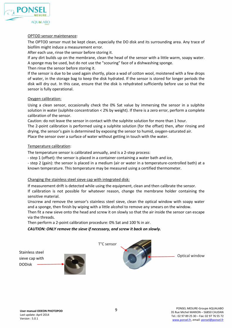
Changing the stainless steel sieve cap with integrated disk:
If measurement drift is detected while using the equipment, clean and then calibrate the sensor. If calibration is not possible for whatever reason, change the membrane holder containing the sensitive material. Unscrew and remove the sensor's stainless steel sieve, clean the optical window with soapy water and a sponge, then finish by wiping with a little alcohol to remove any smears on the window. Then fit a new sieve onto the head and screw it on slowly so that the air inside the sensor can escape via the threads. Then perform a 2-point calibration procedure: 0% Sat and 100 % in air.
CAUTION: ONLY remove the sieve if necessary, and screw it back on slowly.
Stainless steel
sieve cap with
DODisk
Optical window
T°C sensor
10
PONSEL MESURE-Groupe AQUALABO 35 Rue Michel MARION – 56850 CAUDAN Tel.: 02 97 89 25 30 – Fax: 02 97 76 55 72 www.ponsel.fr, email: [email protected]
User manual ODEON PHOTOPOD Last update: April 2014 Version : 5.0.1
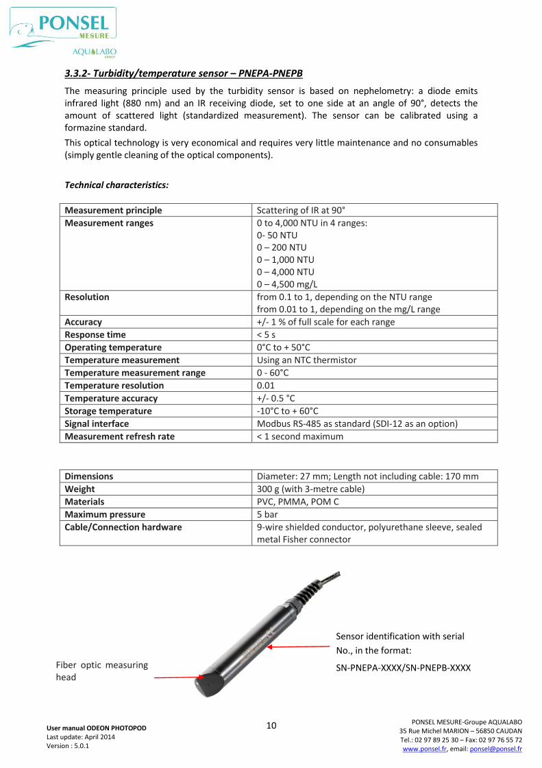
3.3.2- Turbidity/temperature sensor – PNEPA-PNEPB
The measuring principle used by the turbidity sensor is based on nephelometry: a diode emits infrared light (880 nm) and an IR receiving diode, set to one side at an angle of 90°, detects the amount of scattered light (standardized measurement). The sensor can be calibrated using a formazine standard.
This optical technology is very economical and requires very little maintenance and no consumables (simply gentle cleaning of the optical components).
Technical characteristics:
Measurement principle Scattering of IR at 90°
Measurement ranges 0 to 4,000 NTU in 4 ranges: 0- 50 NTU 0 – 200 NTU 0 – 1,000 NTU 0 – 4,000 NTU 0 – 4,500 mg/L
Resolution from 0.1 to 1, depending on the NTU range from 0.01 to 1, depending on the mg/L range
Accuracy +/- 1 % of full scale for each range
Response time < 5 s
Operating temperature 0°C to + 50°C
Temperature measurement Using an NTC thermistor
Temperature measurement range 0 - 60°C
Temperature resolution 0.01
Temperature accuracy +/- 0.5 °C
Storage temperature -10°C to + 60°C
Signal interface Modbus RS-485 as standard (SDI-12 as an option)
Measurement refresh rate < 1 second maximum
Dimensions Diameter: 27 mm; Length not including cable: 170 mm
Weight 300 g (with 3-metre cable)
Materials PVC, PMMA, POM C
Maximum pressure 5 bar
Cable/Connection hardware 9-wire shielded conductor, polyurethane sleeve, sealed metal Fisher connector
Fiber optic measuring head
Sensor identification with serial
No., in the format:
SN-PNEPA-XXXX/SN-PNEPB-XXXX
11
PONSEL MESURE-Groupe AQUALABO 35 Rue Michel MARION – 56850 CAUDAN Tel.: 02 97 89 25 30 – Fax: 02 97 76 55 72 www.ponsel.fr, email: [email protected]
User manual ODEON PHOTOPOD Last update: April 2014 Version : 5.0.1
NTU sensor maintenance:
The NTU (Nephelometry Turbidity Unit) sensor must be kept clean, especially the head and surrounding area containing the optical fibers. Any trace of biofilm or dirt might induce a measurement error.
After each use, rinse the sensor before storing it.
If any dirt builds up on the sensor's head, clean it off with a little warm, soapy water. A sponge may be used, but do not use the "scouring" face of a dishwashing sponge.
Then rinse the sensor before storing it.
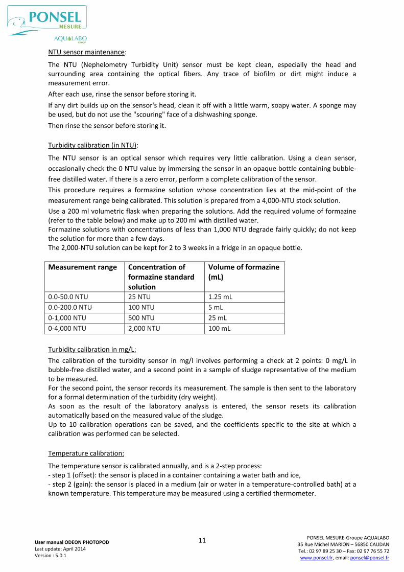
Turbidity calibration (in NTU):
The NTU sensor is an optical sensor which requires very little calibration. Using a clean sensor,
occasionally check the 0 NTU value by immersing the sensor in an opaque bottle containing bubble-
free distilled water. If there is a zero error, perform a complete calibration of the sensor.
This procedure requires a formazine solution whose concentration lies at the mid-point of the
measurement range being calibrated. This solution is prepared from a 4,000-NTU stock solution.
Use a 200 ml volumetric flask when preparing the solutions. Add the required volume of formazine (refer to the table below) and make up to 200 ml with distilled water. Formazine solutions with concentrations of less than 1,000 NTU degrade fairly quickly; do not keep the solution for more than a few days. The 2,000-NTU solution can be kept for 2 to 3 weeks in a fridge in an opaque bottle.
Measurement range Concentration of formazine standard solution
Volume of formazine (mL)
0.0-50.0 NTU 25 NTU 1.25 mL
0.0-200.0 NTU 100 NTU 5 mL
0-1,000 NTU 500 NTU 25 mL
0-4,000 NTU 2,000 NTU 100 mL
Turbidity calibration in mg/L:
The calibration of the turbidity sensor in mg/l involves performing a check at 2 points: 0 mg/L in bubble-free distilled water, and a second point in a sample of sludge representative of the medium to be measured. For the second point, the sensor records its measurement. The sample is then sent to the laboratory for a formal determination of the turbidity (dry weight). As soon as the result of the laboratory analysis is entered, the sensor resets its calibration automatically based on the measured value of the sludge. Up to 10 calibration operations can be saved, and the coefficients specific to the site at which a calibration was performed can be selected.
Temperature calibration:
The temperature sensor is calibrated annually, and is a 2-step process: - step 1 (offset): the sensor is placed in a container containing a water bath and ice, - step 2 (gain): the sensor is placed in a medium (air or water in a temperature-controlled bath) at a known temperature. This temperature may be measured using a certified thermometer.
12
PONSEL MESURE-Groupe AQUALABO 35 Rue Michel MARION – 56850 CAUDAN Tel.: 02 97 89 25 30 – Fax: 02 97 76 55 72 www.ponsel.fr, email: [email protected]
User manual ODEON PHOTOPOD Last update: April 2014 Version : 5.0.1
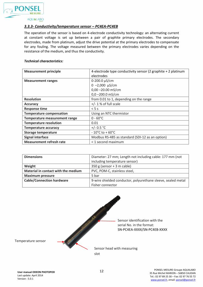
3.3.3- Conductivity/temperature sensor – PC4EA-PC4EB
The operation of the sensor is based on 4-electrode conductivity technology: an alternating current at constant voltage is set up between a pair of graphite primary electrodes. The secondary electrodes, made from platinum, adjust the drive potential at the primary electrodes to compensate for any fouling. The voltage measured between the primary electrodes varies depending on the resistance of the medium, and thus the conductivity.
Technical characteristics:
Measurement principle 4-electrode type conductivity sensor (2 graphite + 2 platinum
electrodes
Measurement ranges 0-200.0 µS/cm 0 –2,000 µS/cm 0,00 –20.00 mS/cm 0,0 –200.0 mS/cm
Resolution from 0.01 to 1, depending on the range
Accuracy +/- 1 % of full scale
Response time < 5 s
Temperature compensation Using an NTC thermistor
Temperature measurement range 0 - 60°C
Temperature resolution 0.01
Temperature accuracy +/- 0.5 °C
Storage temperature - 10°C to + 60°C
Signal interface Modbus RS-485 as standard (SDI-12 as an option)
Measurement refresh rate < 1 second maximum
Dimensions Diameter: 27 mm; Length not including cable: 177 mm (not
including temperature sensor)
Weight 350 g (sensor + 3 m cable)
Material in contact with the medium PVC, POM-C, stainless steel,
Maximum pressure 5 bar
Cable/Connection hardware 9-wire shielded conductor, polyurethane sleeve, sealed metal Fisher connector
Temperature sensor
Sensor head with measuring
slot
Sensor identification with the serial No. in the format: SN-PC4EA-XXXX/SN-PC4EB-XXXX
13
PONSEL MESURE-Groupe AQUALABO 35 Rue Michel MARION – 56850 CAUDAN Tel.: 02 97 89 25 30 – Fax: 02 97 76 55 72 www.ponsel.fr, email: [email protected]
User manual ODEON PHOTOPOD Last update: April 2014 Version : 5.0.1
C4E sensor maintenance:
The C4E sensor uses a 4–electrode conductivity measuring principle, and care must be taken to maintain these 4 electrodes in optimal working condition. After each use, rinse the sensor before storing it. To clean the electrodes (made from graphite and platinum), insert and retract an abrasive strip through the slot in the sensor, under a stream of running water.
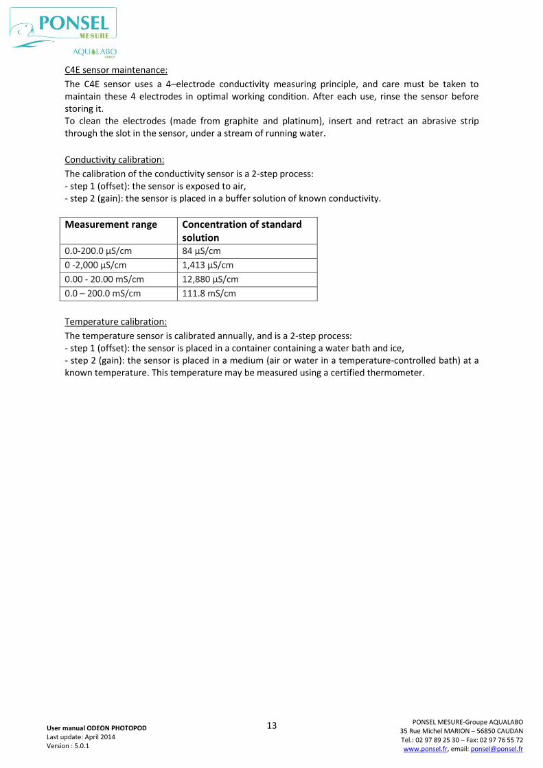
Conductivity calibration:
The calibration of the conductivity sensor is a 2-step process: - step 1 (offset): the sensor is exposed to air, - step 2 (gain): the sensor is placed in a buffer solution of known conductivity.
Measurement range Concentration of standard solution
0.0-200.0 µS/cm 84 µS/cm
0 -2,000 µS/cm 1,413 µS/cm
0.00 - 20.00 mS/cm 12,880 µS/cm
0.0 – 200.0 mS/cm 111.8 mS/cm
Temperature calibration:
The temperature sensor is calibrated annually, and is a 2-step process: - step 1 (offset): the sensor is placed in a container containing a water bath and ice, - step 2 (gain): the sensor is placed in a medium (air or water in a temperature-controlled bath) at a known temperature. This temperature may be measured using a certified thermometer.
14
PONSEL MESURE-Groupe AQUALABO 35 Rue Michel MARION – 56850 CAUDAN Tel.: 02 97 89 25 30 – Fax: 02 97 76 55 72 www.ponsel.fr, email: [email protected]
User manual ODEON PHOTOPOD Last update: April 2014 Version : 5.0.1
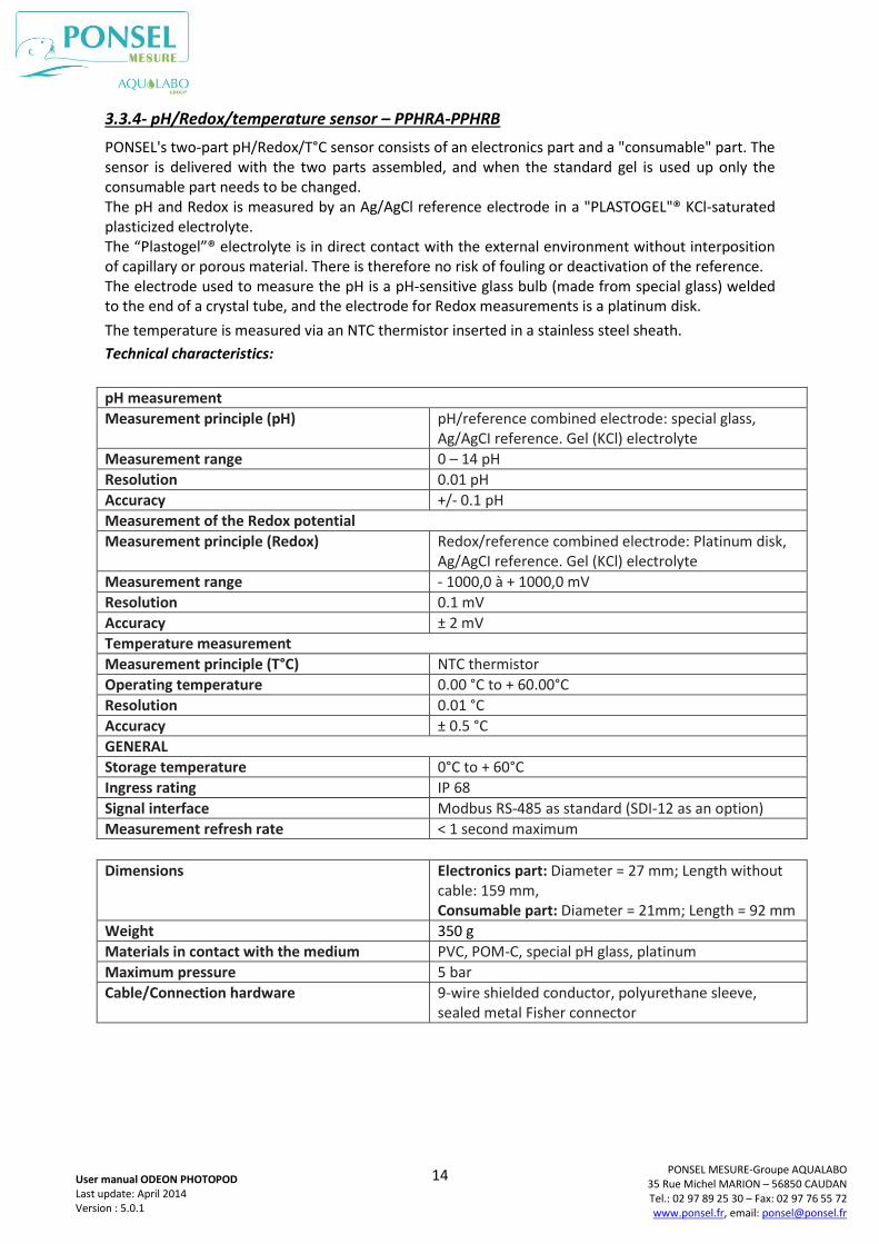
3.3.4- pH/Redox/temperature sensor – PPHRA-PPHRB
PONSEL's two-part pH/Redox/T°C sensor consists of an electronics part and a "consumable" part. The sensor is delivered with the two parts assembled, and when the standard gel is used up only the consumable part needs to be changed. The pH and Redox is measured by an Ag/AgCl reference electrode in a "PLASTOGEL"® KCl-saturated plasticized electrolyte. The “Plastogel”® electrolyte is in direct contact with the external environment without interposition of capillary or porous material. There is therefore no risk of fouling or deactivation of the reference. The electrode used to measure the pH is a pH-sensitive glass bulb (made from special glass) welded to the end of a crystal tube, and the electrode for Redox measurements is a platinum disk.
The temperature is measured via an NTC thermistor inserted in a stainless steel sheath.
Technical characteristics:
pH measurement
Measurement principle (pH) pH/reference combined electrode: special glass, Ag/AgCI reference. Gel (KCl) electrolyte
Measurement range 0 – 14 pH
Resolution 0.01 pH
Accuracy +/- 0.1 pH
Measurement of the Redox potential
Measurement principle (Redox) Redox/reference combined electrode: Platinum disk, Ag/AgCI reference. Gel (KCl) electrolyte
Measurement range - 1000,0 à + 1000,0 mV
Resolution 0.1 mV
Accuracy ± 2 mV
Temperature measurement
Measurement principle (T°C) NTC thermistor
Operating temperature 0.00 °C to + 60.00°C
Resolution 0.01 °C
Accuracy ± 0.5 °C
GENERAL
Storage temperature 0°C to + 60°C
Ingress rating IP 68
Signal interface Modbus RS-485 as standard (SDI-12 as an option)
Measurement refresh rate < 1 second maximum
Dimensions Electronics part: Diameter = 27 mm; Length without
cable: 159 mm, Consumable part: Diameter = 21mm; Length = 92 mm
Weight 350 g
Materials in contact with the medium PVC, POM-C, special pH glass, platinum
Maximum pressure 5 bar
Cable/Connection hardware 9-wire shielded conductor, polyurethane sleeve, sealed metal Fisher connector
15
PONSEL MESURE-Groupe AQUALABO 35 Rue Michel MARION – 56850 CAUDAN Tel.: 02 97 89 25 30 – Fax: 02 97 76 55 72 www.ponsel.fr, email: [email protected]
User manual ODEON PHOTOPOD Last update: April 2014 Version : 5.0.1
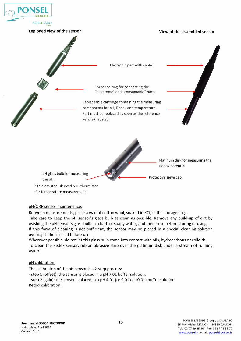
Exploded view of the sensor
pH/ORP sensor maintenance:
Between measurements, place a wad of cotton wool, soaked in KCl, in the storage bag. Take care to keep the pH sensor’s glass bulb as clean as possible. Remove any build-up of dirt by washing the pH sensor’s glass bulb in a bath of soapy water, and then rinse before storing or using. If this form of cleaning is not sufficient, the sensor may be placed in a special cleaning solution overnight, then rinsed before use. Wherever possible, do not let this glass bulb come into contact with oils, hydrocarbons or colloids, To clean the Redox sensor, rub an abrasive strip over the platinum disk under a stream of running water.
pH calibration:
The calibration of the pH sensor is a 2-step process: - step 1 (offset): the sensor is placed in a pH 7.01 buffer solution. - step 2 (gain): the sensor is placed in a pH 4.01 (or 9.01 or 10.01) buffer solution. Redox calibration:
View of the assembled sensor
Electronic part with cable
Threaded ring for connecting the “electronic” and “consumable” parts
pH glass bulb for measuring
the pH.
Stainless steel sleeved NTC thermistor
for temperature measurement
Platinum disk for measuring the
Redox potential
Protective sieve cap
Replaceable cartridge containing the measuring
components for pH, Redox and temperature.
Part must be replaced as soon as the reference
gel is exhausted.
16
PONSEL MESURE-Groupe AQUALABO 35 Rue Michel MARION – 56850 CAUDAN Tel.: 02 97 89 25 30 – Fax: 02 97 76 55 72 www.ponsel.fr, email: [email protected]
User manual ODEON PHOTOPOD Last update: April 2014 Version : 5.0.1
The calibration of the Redox sensor is a 2-step process:
- step 1 (offset): the sensor is exposed to air for the 0 mV value,
- step 2 (gain): the sensor is placed in a buffer solution (240 mV or 470 mV).
Temperature calibration:
The temperature sensor is calibrated annually, and is a 2-step process: - step 1 (offset): the sensor is placed in a container containing a water bath and ice, - step 2 (gain): the sensor is placed in a medium (air or water in a temperature-controlled bath) at a known temperature. This temperature may be measured using a certified thermometer.
17
PONSEL MESURE-Groupe AQUALABO 35 Rue Michel MARION – 56850 CAUDAN Tel.: 02 97 89 25 30 – Fax: 02 97 76 55 72 www.ponsel.fr, email: [email protected]
User manual ODEON PHOTOPOD Last update: April 2014 Version : 5.0.1
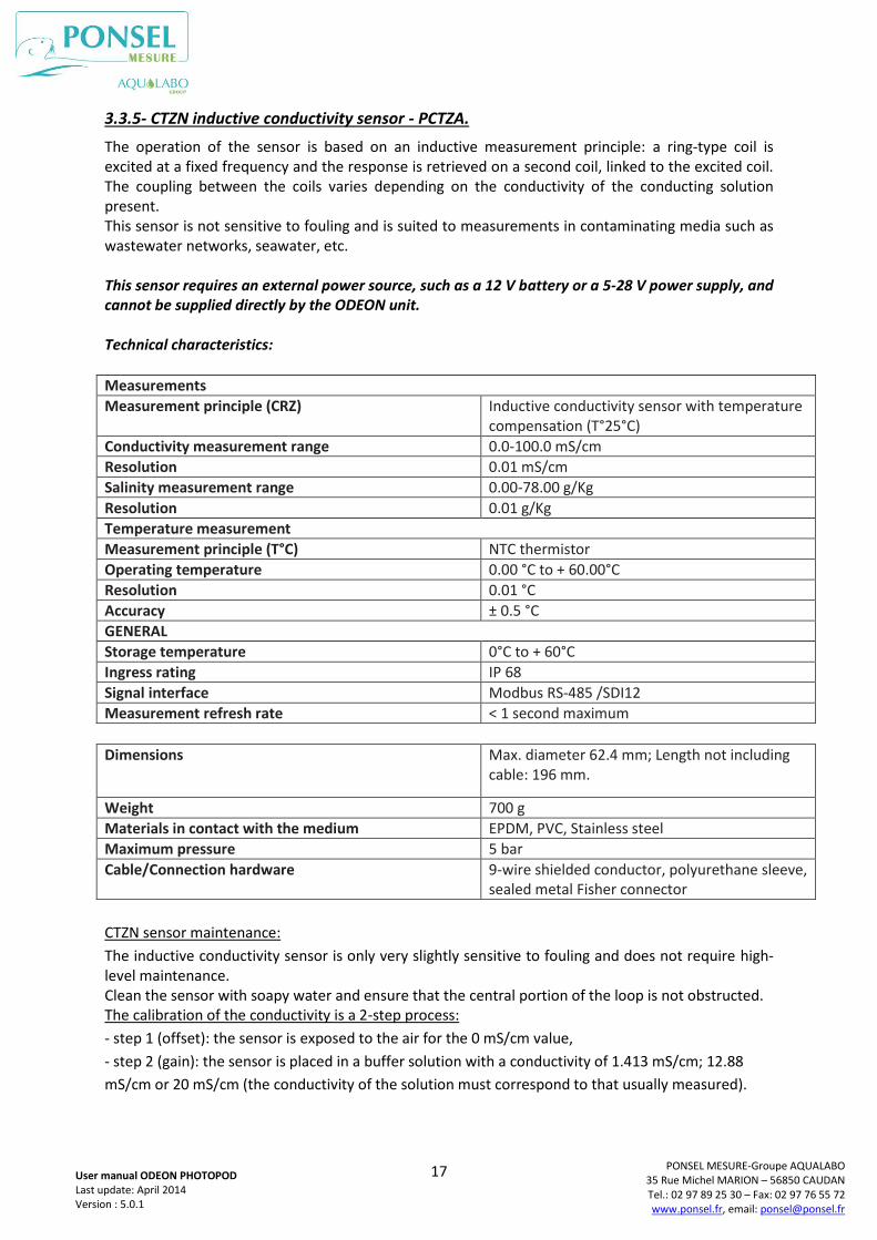
3.3.5- CTZN inductive conductivity sensor - PCTZA.
The operation of the sensor is based on an inductive measurement principle: a ring-type coil is excited at a fixed frequency and the response is retrieved on a second coil, linked to the excited coil. The coupling between the coils varies depending on the conductivity of the conducting solution present. This sensor is not sensitive to fouling and is suited to measurements in contaminating media such as wastewater networks, seawater, etc. This sensor requires an external power source, such as a 12 V battery or a 5-28 V power supply, and cannot be supplied directly by the ODEON unit. Technical characteristics:
Measurements
Measurement principle (CRZ) Inductive conductivity sensor with temperature compensation (T°25°C)
Conductivity measurement range 0.0-100.0 mS/cm
Resolution 0.01 mS/cm
Salinity measurement range 0.00-78.00 g/Kg
Resolution 0.01 g/Kg
Temperature measurement
Measurement principle (T°C) NTC thermistor
Operating temperature 0.00 °C to + 60.00°C
Resolution 0.01 °C
Accuracy ± 0.5 °C
GENERAL
Storage temperature 0°C to + 60°C
Ingress rating IP 68
Signal interface Modbus RS-485 /SDI12
Measurement refresh rate < 1 second maximum
Dimensions Max. diameter 62.4 mm; Length not including
cable: 196 mm.
Weight 700 g
Materials in contact with the medium EPDM, PVC, Stainless steel
Maximum pressure 5 bar
Cable/Connection hardware 9-wire shielded conductor, polyurethane sleeve, sealed metal Fisher connector
CTZN sensor maintenance:
The inductive conductivity sensor is only very slightly sensitive to fouling and does not require high-level maintenance. Clean the sensor with soapy water and ensure that the central portion of the loop is not obstructed. The calibration of the conductivity is a 2-step process:
- step 1 (offset): the sensor is exposed to the air for the 0 mS/cm value,
- step 2 (gain): the sensor is placed in a buffer solution with a conductivity of 1.413 mS/cm; 12.88
mS/cm or 20 mS/cm (the conductivity of the solution must correspond to that usually measured).
18
PONSEL MESURE-Groupe AQUALABO 35 Rue Michel MARION – 56850 CAUDAN Tel.: 02 97 89 25 30 – Fax: 02 97 76 55 72 www.ponsel.fr, email: [email protected]
User manual ODEON PHOTOPOD Last update: April 2014 Version : 5.0.1
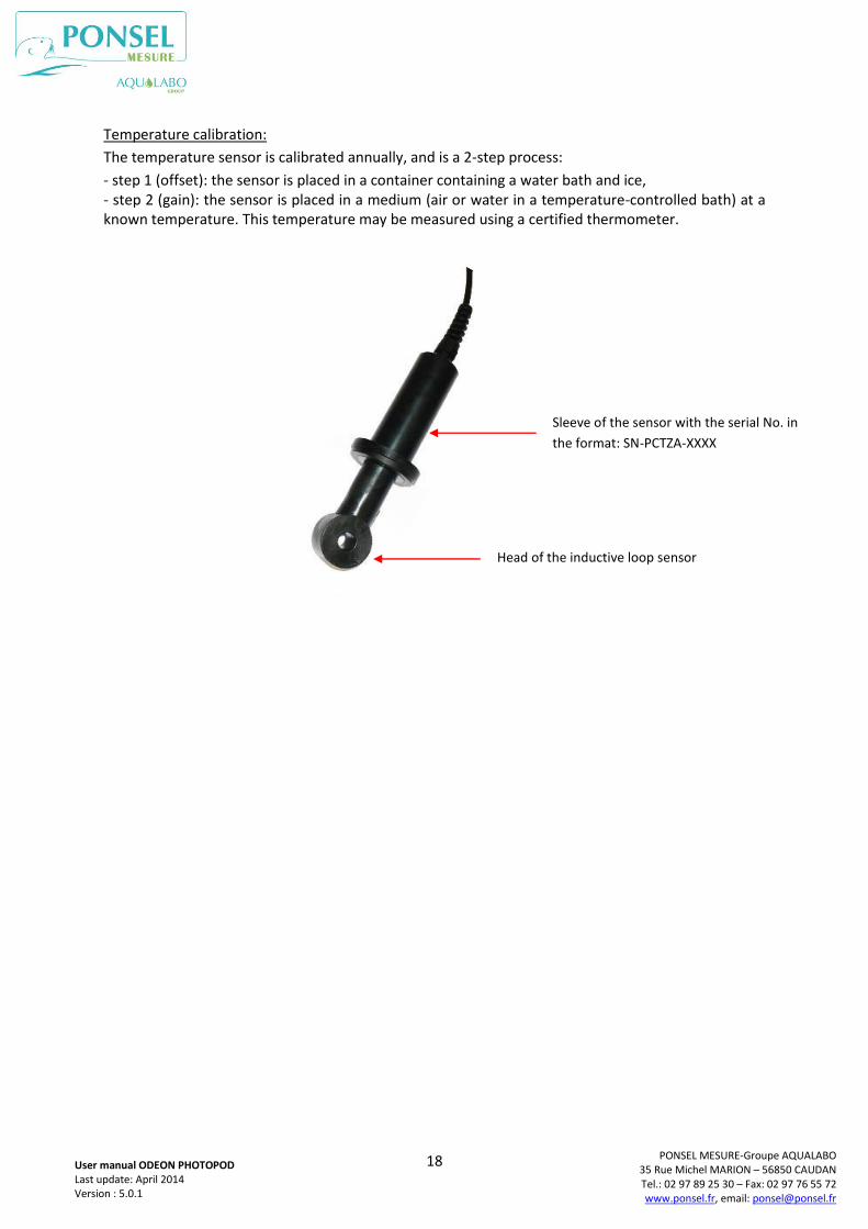
Temperature calibration:
The temperature sensor is calibrated annually, and is a 2-step process:
- step 1 (offset): the sensor is placed in a container containing a water bath and ice, - step 2 (gain): the sensor is placed in a medium (air or water in a temperature-controlled bath) at a known temperature. This temperature may be measured using a certified thermometer.
Sleeve of the sensor with the serial No. in
the format: SN-PCTZA-XXXX
Head of the inductive loop sensor
19
PONSEL MESURE-Groupe AQUALABO 35 Rue Michel MARION – 56850 CAUDAN Tel.: 02 97 89 25 30 – Fax: 02 97 76 55 72 www.ponsel.fr, email: [email protected]
User manual ODEON PHOTOPOD Last update: April 2014 Version : 5.0.1
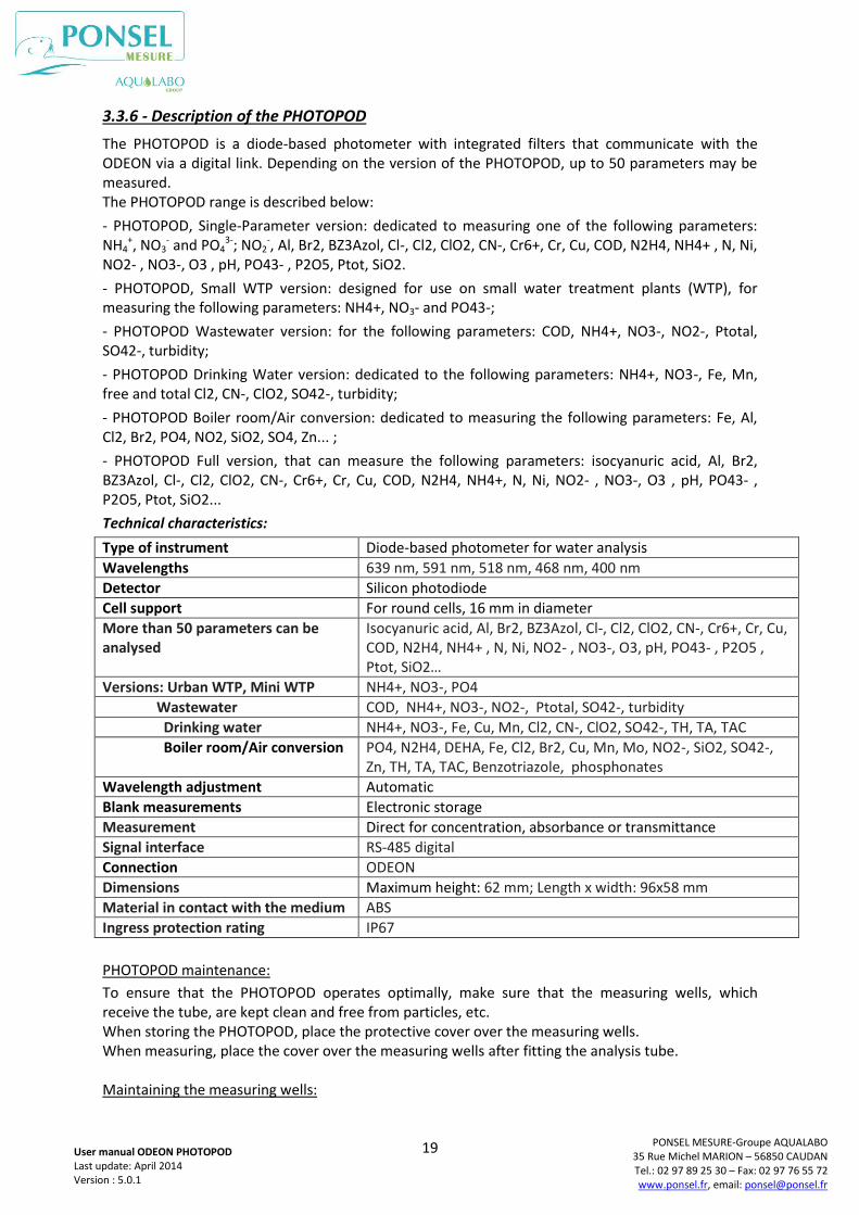
3.3.6 - Description of the PHOTOPOD
The PHOTOPOD is a diode-based photometer with integrated filters that communicate with the ODEON via a digital link. Depending on the version of the PHOTOPOD, up to 50 parameters may be measured. The PHOTOPOD range is described below:
- PHOTOPOD, Single-Parameter version: dedicated to measuring one of the following parameters: NH4
+, NO3- and PO4
3-; NO2-, Al, Br2, BZ3Azol, Cl-, Cl2, ClO2, CN-, Cr6+, Cr, Cu, COD, N2H4, NH4+ , N, Ni,
NO2- , NO3-, O3 , pH, PO43- , P2O5, Ptot, SiO2.
- PHOTOPOD, Small WTP version: designed for use on small water treatment plants (WTP), for measuring the following parameters: NH4+, NO3- and PO43-;
- PHOTOPOD Wastewater version: for the following parameters: COD, NH4+, NO3-, NO2-, Ptotal, SO42-, turbidity;
- PHOTOPOD Drinking Water version: dedicated to the following parameters: NH4+, NO3-, Fe, Mn, free and total Cl2, CN-, ClO2, SO42-, turbidity;
- PHOTOPOD Boiler room/Air conversion: dedicated to measuring the following parameters: Fe, Al, Cl2, Br2, PO4, NO2, SiO2, SO4, Zn... ;
- PHOTOPOD Full version, that can measure the following parameters: isocyanuric acid, Al, Br2, BZ3Azol, Cl-, Cl2, ClO2, CN-, Cr6+, Cr, Cu, COD, N2H4, NH4+, N, Ni, NO2- , NO3-, O3 , pH, PO43- , P2O5, Ptot, SiO2...
Technical characteristics:
Type of instrument Diode-based photometer for water analysis
Wavelengths 639 nm, 591 nm, 518 nm, 468 nm, 400 nm
Detector Silicon photodiode
Cell support For round cells, 16 mm in diameter
More than 50 parameters can be analysed
Isocyanuric acid, Al, Br2, BZ3Azol, Cl-, Cl2, ClO2, CN-, Cr6+, Cr, Cu, COD, N2H4, NH4+ , N, Ni, NO2- , NO3-, O3, pH, PO43- , P2O5 , Ptot, SiO2…
Versions: Urban WTP, Mini WTP NH4+, NO3-, PO4
Wastewater COD, NH4+, NO3-, NO2-, Ptotal, SO42-, turbidity
Drinking water NH4+, NO3-, Fe, Cu, Mn, Cl2, CN-, ClO2, SO42-, TH, TA, TAC
Boiler room/Air conversion PO4, N2H4, DEHA, Fe, Cl2, Br2, Cu, Mn, Mo, NO2-, SiO2, SO42-, Zn, TH, TA, TAC, Benzotriazole, phosphonates
Wavelength adjustment Automatic
Blank measurements Electronic storage
Measurement Direct for concentration, absorbance or transmittance
Signal interface RS-485 digital
Connection ODEON
Dimensions Maximum height: 62 mm; Length x width: 96x58 mm
Material in contact with the medium ABS
Ingress protection rating IP67
PHOTOPOD maintenance:
To ensure that the PHOTOPOD operates optimally, make sure that the measuring wells, which receive the tube, are kept clean and free from particles, etc. When storing the PHOTOPOD, place the protective cover over the measuring wells. When measuring, place the cover over the measuring wells after fitting the analysis tube. Maintaining the measuring wells:
20
PONSEL MESURE-Groupe AQUALABO 35 Rue Michel MARION – 56850 CAUDAN Tel.: 02 97 89 25 30 – Fax: 02 97 76 55 72 www.ponsel.fr, email: [email protected]
User manual ODEON PHOTOPOD Last update: April 2014 Version : 5.0.1
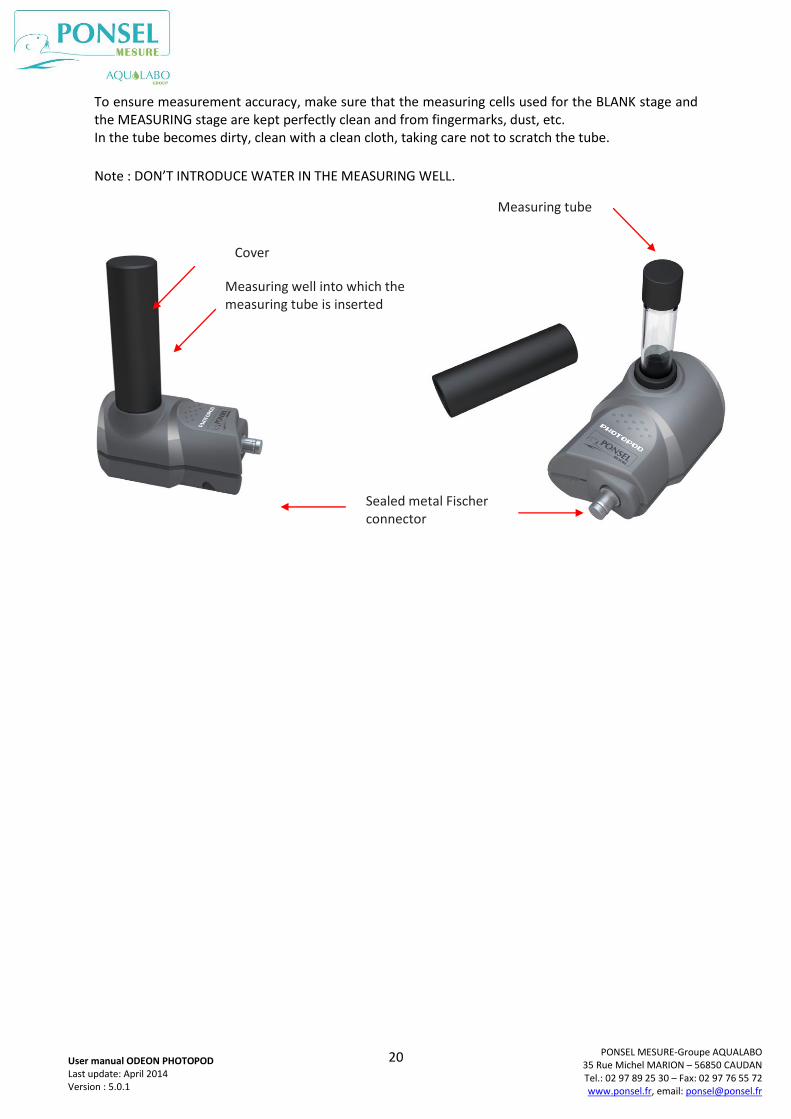
To ensure measurement accuracy, make sure that the measuring cells used for the BLANK stage and the MEASURING stage are kept perfectly clean and from fingermarks, dust, etc. In the tube becomes dirty, clean with a clean cloth, taking care not to scratch the tube.
Note : DON’T INTRODUCE WATER IN THE MEASURING WELL.
Measuring well into which the measuring tube is inserted
Cover
Measuring tube
Sealed metal Fischer connector
21
PONSEL MESURE-Groupe AQUALABO 35 Rue Michel MARION – 56850 CAUDAN Tel.: 02 97 89 25 30 – Fax: 02 97 76 55 72 www.ponsel.fr, email: [email protected]
User manual ODEON PHOTOPOD Last update: April 2014 Version : 5.0.1
4. USING THE ODEON
4.1 – Power supply
4.1.1-Restrictions on battery type
The user must never combine different types of batteries, or connect a charger to an ODEON fitted with alkaline batteries: this could lead to a fire or explosion.
4.1.2-Changing the batteries
Change flat 4 AA alkaline batteries in a clean, dry room, so as not to contaminate the inside of the unit.
Check that the polarity of the batteries fitted matches the polarity indicated in the battery compartment.
When closing the unit, the operator should check that:
- the power cable linking the battery holder to the electronic card is not caught,
- the seal between the two elements of the unit is fitted correctly,
- that all 8 original screws are tightened firmly to compress the seal between the two elements of the unit.
If these instructions are not followed, the ODEON may malfunction or allow the ingress of fluids.
The user must also regularly check the batteries to prevent the equipment from being damaged by discharged batteries.
4.1.3- Using rechargeable batteries
The ODEON may be fitted with 4 NiMH rechargeable batteries which can be recharged directly inside the unit, but only by using the cable provided by the manufacturer. The unit will warm up slightly during charging.
Note that the charger provided for the ODEON is not sealed. This accessory cannot be used in wet conditions (when measuring in the field), but is compatible with use in a laboratory.
Similarly, the ODEON-PC USB link should only be used in an office. The user must take responsibility for any problems encountered when transferring data to a portable computer in the field (in wet or damp conditions).
4.1.4- Prolonged storage or use
NiMH batteries discharge slowly when not in use. Before starting a measurement campaign, users should check the battery status indicated by the icon in the top right-hand corner of the screen. If the ODEON is stored for a long time the rechargeable batteries will discharge; they must be recharged regularly so that they do not drop below the minimum charge level.
If the output voltage of the alkaline or NiMH batteries is too low, the screen will flash and shortly afterwards the unit will shut-down automatically. However, the data saved will be preserved.
When preparing for a long campaign of measurements, it is a good idea to fit new alkaline batteries or to fully charge the NiMH batteries.
Users can also connect the ODEON to an external 12V power source via the cable provided as an option.
22
PONSEL MESURE-Groupe AQUALABO 35 Rue Michel MARION – 56850 CAUDAN Tel.: 02 97 89 25 30 – Fax: 02 97 76 55 72 www.ponsel.fr, email: [email protected]
User manual ODEON PHOTOPOD Last update: April 2014 Version : 5.0.1
4.2 – Connecting sensors and the PHOTOPOD.
4.2.1-Connecting digital sensors.
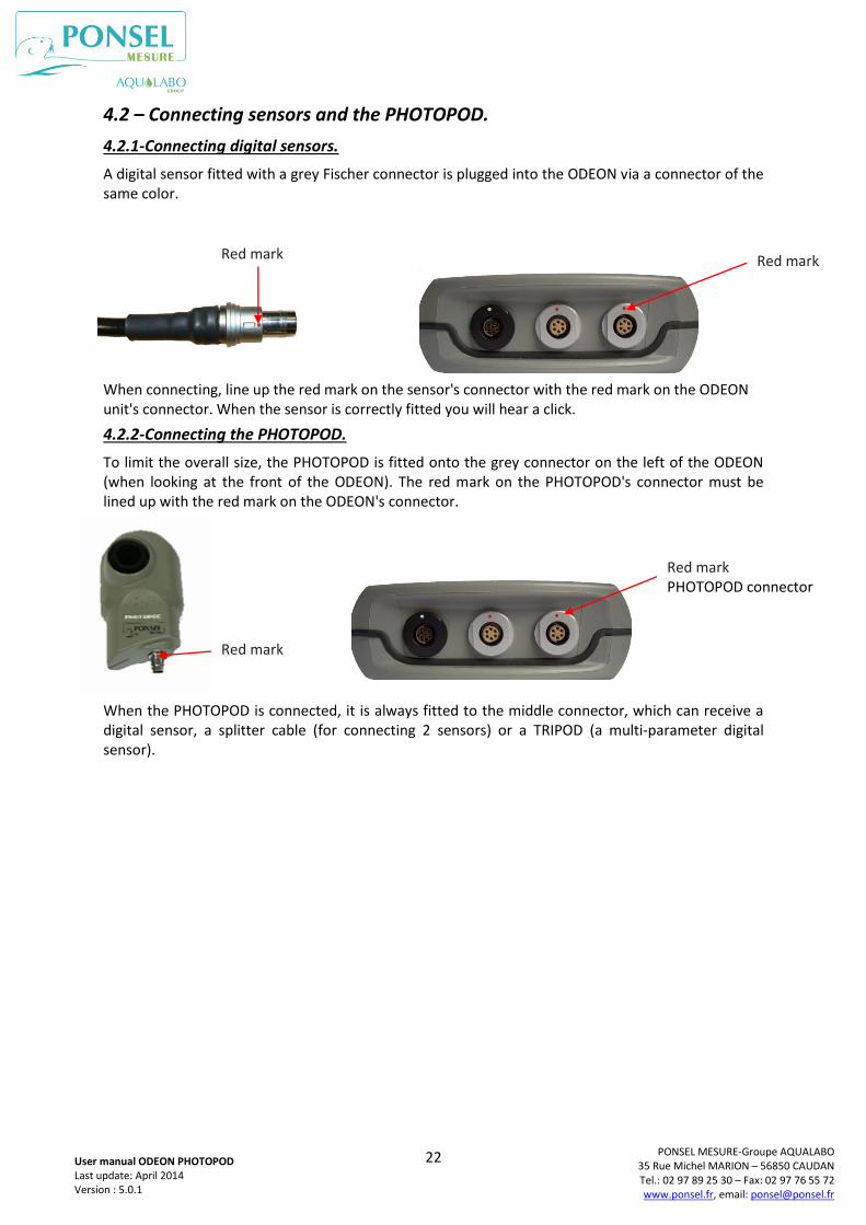
A digital sensor fitted with a grey Fischer connector is plugged into the ODEON via a connector of the same color.
When connecting, line up the red mark on the sensor's connector with the red mark on the ODEON unit's connector. When the sensor is correctly fitted you will hear a click.
4.2.2-Connecting the PHOTOPOD.
To limit the overall size, the PHOTOPOD is fitted onto the grey connector on the left of the ODEON (when looking at the front of the ODEON). The red mark on the PHOTOPOD's connector must be lined up with the red mark on the ODEON's connector.
When the PHOTOPOD is connected, it is always fitted to the middle connector, which can receive a digital sensor, a splitter cable (for connecting 2 sensors) or a TRIPOD (a multi-parameter digital sensor).
Red mark
Red mark PHOTOPOD connector
Red mark
Red mark
23
PONSEL MESURE-Groupe AQUALABO 35 Rue Michel MARION – 56850 CAUDAN Tel.: 02 97 89 25 30 – Fax: 02 97 76 55 72 www.ponsel.fr, email: [email protected]
User manual ODEON PHOTOPOD Last update: April 2014 Version : 5.0.1
4.3 – General functions of the ODEON.
4.3.1 On/Off and standby mode.
On
Press once on the On/Off button to switch on the unit. NOTE: If the unit does not respond, check the power supply (e.g. that the batteries are fitted correctly in the holder).
Backlight
When the ODEON is On, pressing on the On/Off button again switches on the screen's backlight. The backlight stays on for as long as the user uses the keypad. If the keypad is not used, the backlight will switch off after a period of time defined by the user. However, the user can switch off the backlight by pressing again on the On/Off switch.
Off
The ODEON can be shut-down by pressing and holding down the On/Off button for 10 seconds. Standby
If the keypad is not used for 30 seconds (factory setting) the unit will switch automatically to standby mode. The display disappears and no measurement is made. However, if the automatic recording function has been enabled, measurements will be made and saved at the frequency set by the user.
When the screen is in standby mode, it can be reactivated by pressing any keyboard button.
The time periods for switching to standby and for backlight extinction can be set by the user (these operations are detailed below, in the section on how to use the user interface).
In way of functioning with the PHOTOPOD, the setting in a stand-by mode is deactivated.
4.3.2 Navigation keypad.
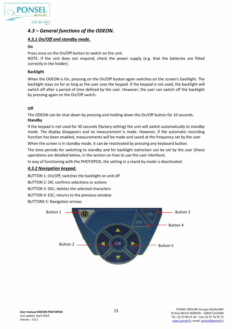
BUTTON 1: On/Off; switches the backlight on and off
BUTTON 2: OK; confirms selections or actions
BUTTON 3: DEL; deletes the selected characters
BUTTON 4: ESC; returns to the previous window
BUTTONS 5: Navigation arrows
Button 1
Button 2
Button 3
Button 4
Button 5
24
PONSEL MESURE-Groupe AQUALABO 35 Rue Michel MARION – 56850 CAUDAN Tel.: 02 97 89 25 30 – Fax: 02 97 76 55 72 www.ponsel.fr, email: [email protected]
User manual ODEON PHOTOPOD Last update: April 2014 Version : 5.0.1
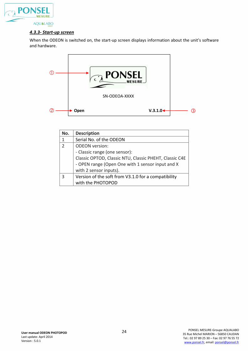
4.3.3- Start-up screen
When the ODEON is switched on, the start-up screen displays information about the unit’s software and hardware.
No. Description
1 Serial No. of the ODEON
2 ODEON version: - Classic range (one sensor): Classic OPTOD, Classic NTU, Classic PHEHT, Classic C4E - OPEN range (Open One with 1 sensor input and X with 2 sensor inputs).
3 Version of the soft from V3.1.0 for a compatibility with the PHOTOPOD
V.3.1.0 Open
SN-ODEOA-XXXX
25
PONSEL MESURE-Groupe AQUALABO 35 Rue Michel MARION – 56850 CAUDAN Tel.: 02 97 89 25 30 – Fax: 02 97 76 55 72 www.ponsel.fr, email: [email protected]
User manual ODEON PHOTOPOD Last update: April 2014 Version : 5.0.1
4.4. Using the unit with digital physico-chemical sensors.
4.4.1- SCAN function
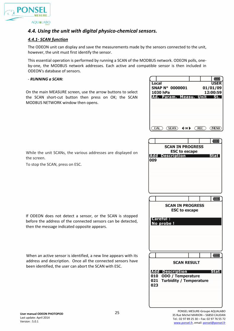
The ODEON unit can display and save the measurements made by the sensors connected to the unit, however, the unit must first identify the sensor.
This essential operation is performed by running a SCAN of the MODBUS network. ODEON polls, one-by-one, the MODBUS network addresses. Each active and compatible sensor is then included in ODEON's database of sensors.
- RUNNING a SCAN:
On the main MEASURE screen, use the arrow buttons to select the SCAN short-cut button then press on OK; the SCAN MODBUS NETWORK window then opens.
While the unit SCANs, the various addresses are displayed on the screen.
To stop the SCAN, press on ESC.
If ODEON does not detect a sensor, or the SCAN is stopped before the address of the connected sensors can be detected, then the message indicated opposite appears.
When an active sensor is identified, a new line appears with its address and description. Once all the connected sensors have been identified, the user can abort the SCAN with ESC.
26
PONSEL MESURE-Groupe AQUALABO 35 Rue Michel MARION – 56850 CAUDAN Tel.: 02 97 89 25 30 – Fax: 02 97 76 55 72 www.ponsel.fr, email: [email protected]
User manual ODEON PHOTOPOD Last update: April 2014 Version : 5.0.1
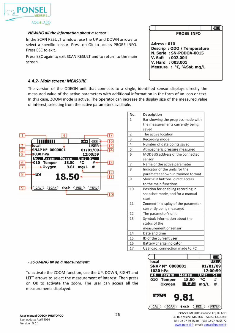
4.4.2- Main screen: MEASURE
The version of the ODEON unit that connects to a single, identified sensor displays directly the measured value of the active parameters with additional information in the form of an icon or text. In this case, ZOOM mode is active. The operator can increase the display size of the measured value of interest, selecting from the active parameters available.
- ZOOMING IN on a measurement:
No. Description
1 Bar showing the progress made with the measurements currently being saved
2 The active location
3 Recording mode
4 Number of data points saved
5 Atmospheric pressure measured
6 MODBUS address of the connected sensor
7 Name of the active parameter
8 Indicator of the units for the parameter shown in zoomed format
9 Short-cut buttons: direct access to the main functions
10 Position for enabling recording in snapshot mode, and for a manual start
11 Zoomed-in display of the parameter currently being measured
12 The parameter’s unit
13 Symbol: information about the status of the measurement or sensor
14 Date and time
15 ID of the current user
16 Battery charge indicator
17 USB logo: connection made to PC
-VIEWING all the information about a sensor:
In the SCAN RESULT window, use the UP and DOWN arrows to select a specific sensor. Press on OK to access PROBE INFO. Press ESC to exit.
Press ESC again to exit SCAN RESULT and to return to the main screen.
To activate the ZOOM function, use the UP, DOWN, RIGHT and LEFT arrows to select the measurement of interest. Then press on OK to activate the zoom. The user can access all the measurements displayed.
27
PONSEL MESURE-Groupe AQUALABO 35 Rue Michel MARION – 56850 CAUDAN Tel.: 02 97 89 25 30 – Fax: 02 97 76 55 72 www.ponsel.fr, email: [email protected]
User manual ODEON PHOTOPOD Last update: April 2014 Version : 5.0.1
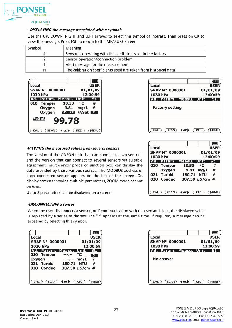
- DISPLAYING the message associated with a symbol:
Use the UP, DOWN, RIGHT and LEFT arrows to select the symbol of interest. Then press on OK to view the message. Press ESC to return to the MEASURE screen.
Symbol Meaning
# Sensor is operating with the coefficients set in the factory ? Sensor operation/connection problem ! Alert message for the measurement H The calibration coefficients used are taken from historical data
-DISCONNECTING a sensor
When the user disconnects a sensor, or if communication with that sensor is lost, the displayed value is replaced by a series of dashes. The "?" appears at the same time. If required, a message can be accessed by selecting this symbol.
-VIEWING the measured values from several sensors
The version of the ODEON unit that can connect to two sensors, and the version that can connect to several sensors via suitable equipment (multi-sensor probe or junction box) can display the data provided by these various sources. The MODBUS address of each connected sensor appears on the left of the screen. On display screens showing multiple parameters, ZOOM mode cannot be used.
Up to 8 parameters can be displayed on a screen.
28
PONSEL MESURE-Groupe AQUALABO 35 Rue Michel MARION – 56850 CAUDAN Tel.: 02 97 89 25 30 – Fax: 02 97 76 55 72 www.ponsel.fr, email: [email protected]
User manual ODEON PHOTOPOD Last update: April 2014 Version : 5.0.1
4.4.3.General functions
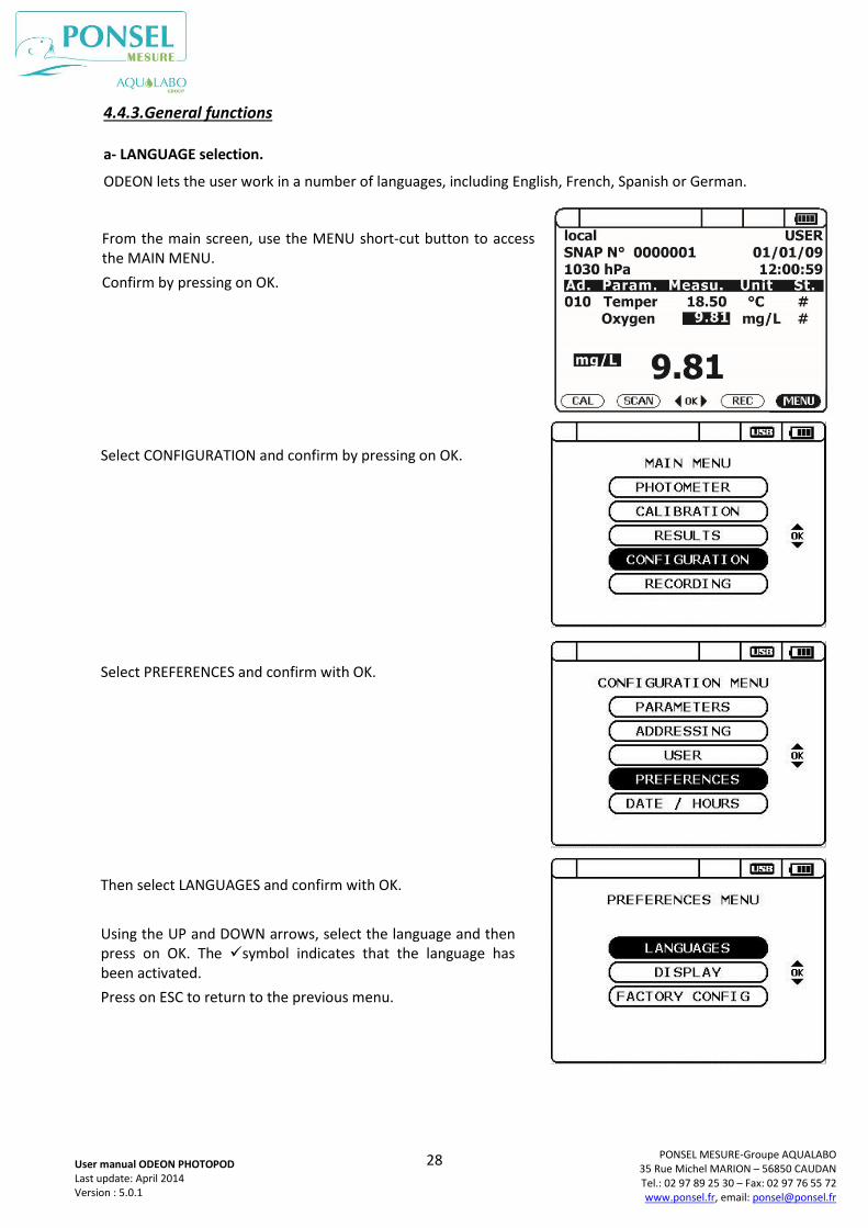
a- LANGUAGE selection.
ODEON lets the user work in a number of languages, including English, French, Spanish or German.
Select CONFIGURATION and confirm by pressing on OK.
Select PREFERENCES and confirm with OK.
Using the UP and DOWN arrows, select the language and then press on OK. The symbol indicates that the language has been activated.
Press on ESC to return to the previous menu.
From the main screen, use the MENU short-cut button to access the MAIN MENU.
Confirm by pressing on OK.
Then select LANGUAGES and confirm with OK.
29
PONSEL MESURE-Groupe AQUALABO 35 Rue Michel MARION – 56850 CAUDAN Tel.: 02 97 89 25 30 – Fax: 02 97 76 55 72 www.ponsel.fr, email: [email protected]
User manual ODEON PHOTOPOD Last update: April 2014 Version : 5.0.1
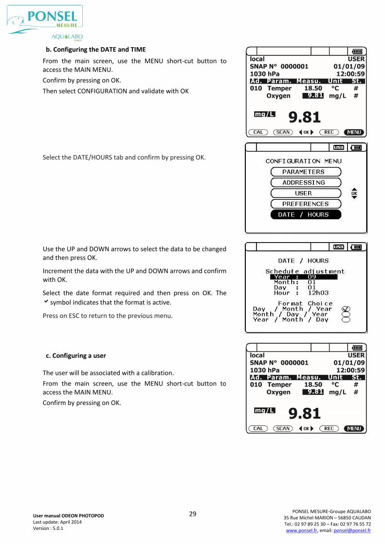
b. Configuring the DATE and TIME
c. Configuring a user
From the main screen, use the MENU short-cut button to access the MAIN MENU.
Confirm by pressing on OK.
Then select CONFIGURATION and validate with OK
Select the DATE/HOURS tab and confirm by pressing OK.
Use the UP and DOWN arrows to select the data to be changed and then press OK.
Increment the data with the UP and DOWN arrows and confirm with OK.
Select the date format required and then press on OK. The
symbol indicates that the format is active.
Press on ESC to return to the previous menu.
The user will be associated with a calibration.
From the main screen, use the MENU short-cut button to access the MAIN MENU.
Confirm by pressing on OK.
30
PONSEL MESURE-Groupe AQUALABO 35 Rue Michel MARION – 56850 CAUDAN Tel.: 02 97 89 25 30 – Fax: 02 97 76 55 72 www.ponsel.fr, email: [email protected]
User manual ODEON PHOTOPOD Last update: April 2014 Version : 5.0.1
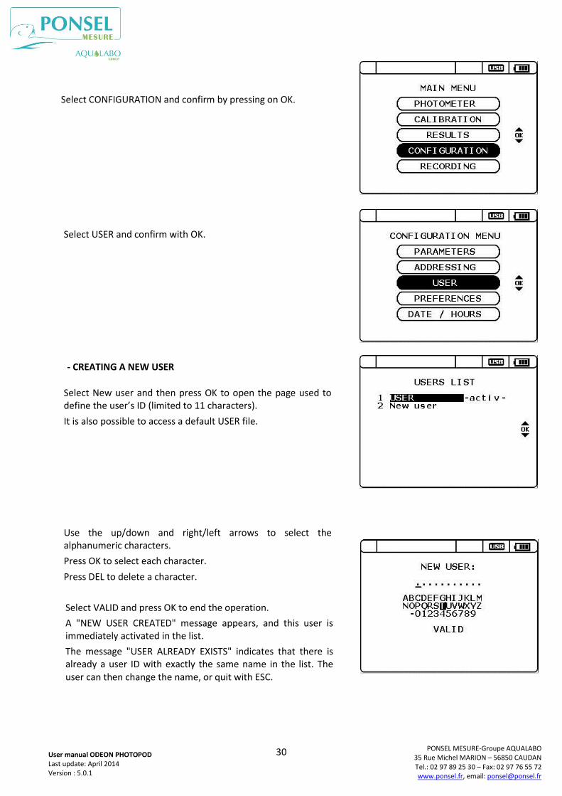
Select CONFIGURATION and confirm by pressing on OK.
Select USER and confirm with OK.
- CREATING A NEW USER
Select New user and then press OK to open the page used to define the user’s ID (limited to 11 characters).
It is also possible to access a default USER file.
Use the up/down and right/left arrows to select the alphanumeric characters.
Press OK to select each character.
Press DEL to delete a character.
Select VALID and press OK to end the operation.
A "NEW USER CREATED" message appears, and this user is immediately activated in the list.
The message "USER ALREADY EXISTS" indicates that there is already a user ID with exactly the same name in the list. The user can then change the name, or quit with ESC.
31
PONSEL MESURE-Groupe AQUALABO 35 Rue Michel MARION – 56850 CAUDAN Tel.: 02 97 89 25 30 – Fax: 02 97 76 55 72 www.ponsel.fr, email: [email protected]
User manual ODEON PHOTOPOD Last update: April 2014 Version : 5.0.1
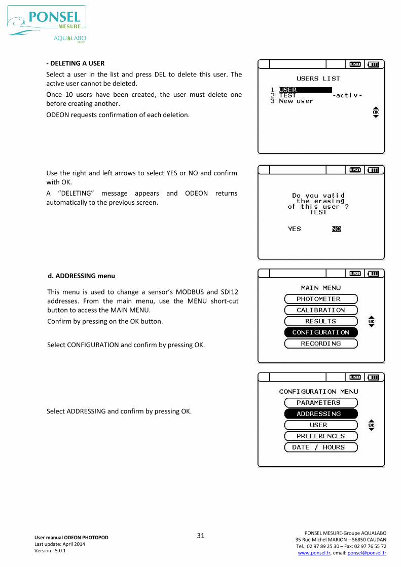
d. ADDRESSING menu
- DELETING A USER
Select a user in the list and press DEL to delete this user. The active user cannot be deleted.
Once 10 users have been created, the user must delete one before creating another.
ODEON requests confirmation of each deletion.
Use the right and left arrows to select YES or NO and confirm with OK.
A “DELETING” message appears and ODEON returns automatically to the previous screen.
This menu is used to change a sensor’s MODBUS and SDI12 addresses. From the main menu, use the MENU short-cut button to access the MAIN MENU.
Confirm by pressing on the OK button.
Select CONFIGURATION and confirm by pressing OK.
Select ADDRESSING and confirm by pressing OK.
32
PONSEL MESURE-Groupe AQUALABO 35 Rue Michel MARION – 56850 CAUDAN Tel.: 02 97 89 25 30 – Fax: 02 97 76 55 72 www.ponsel.fr, email: [email protected]
User manual ODEON PHOTOPOD Last update: April 2014 Version : 5.0.1
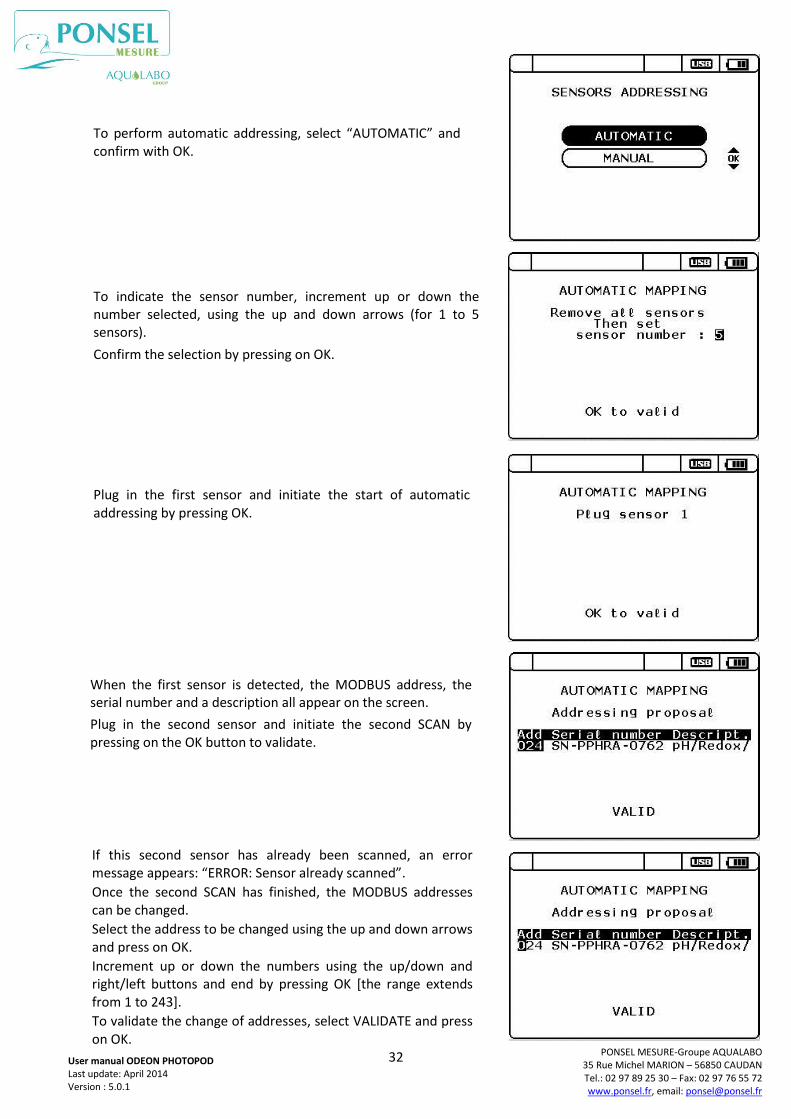
To perform automatic addressing, select “AUTOMATIC” and confirm with OK.
To indicate the sensor number, increment up or down the number selected, using the up and down arrows (for 1 to 5 sensors).
Confirm the selection by pressing on OK.
Plug in the first sensor and initiate the start of automatic addressing by pressing OK.
When the first sensor is detected, the MODBUS address, the serial number and a description all appear on the screen.
Plug in the second sensor and initiate the second SCAN by pressing on the OK button to validate.
If this second sensor has already been scanned, an error message appears: “ERROR: Sensor already scanned”.
Once the second SCAN has finished, the MODBUS addresses can be changed.
Select the address to be changed using the up and down arrows and press on OK.
Increment up or down the numbers using the up/down and right/left buttons and end by pressing OK [the range extends from 1 to 243].
To validate the change of addresses, select VALIDATE and press on OK.
33
PONSEL MESURE-Groupe AQUALABO 35 Rue Michel MARION – 56850 CAUDAN Tel.: 02 97 89 25 30 – Fax: 02 97 76 55 72 www.ponsel.fr, email: [email protected]
User manual ODEON PHOTOPOD Last update: April 2014 Version : 5.0.1
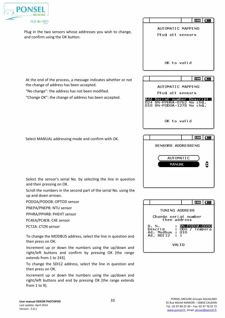
Plug in the two sensors whose addresses you wish to change, and confirm using the OK button.
At the end of the process, a message indicates whether or not the change of address has been accepted.
“No change”: the address has not been modified.
“Change OK”: the change of address has been accepted.
Select MANUAL addressing mode and confirm with OK.
Select the sensor’s serial No. by selecting the line in question and then pressing on OK.
Scroll the numbers in the second part of the serial No. using the up and down arrows.
PODOA/PODOB: OPTOD sensor
PNEPA/PNEPB: NTU sensor
PPHRA/PPHRB: PHEHT sensor
PC4EA/PC4EB: C4E sensor
PCTZA: CTZN sensor
To change the MODBUS address, select the line in question and then press on OK.
Increment up or down the numbers using the up/down and right/left buttons and confirm by pressing OK [the range extends from 1 to 243].
To change the SDI12 address, select the line in question and then press on OK.
Increment up or down the numbers using the up/down and right/left buttons and end by pressing OK [the range extends from 1 to 9].
34
PONSEL MESURE-Groupe AQUALABO 35 Rue Michel MARION – 56850 CAUDAN Tel.: 02 97 89 25 30 – Fax: 02 97 76 55 72 www.ponsel.fr, email: [email protected]
User manual ODEON PHOTOPOD Last update: April 2014 Version : 5.0.1
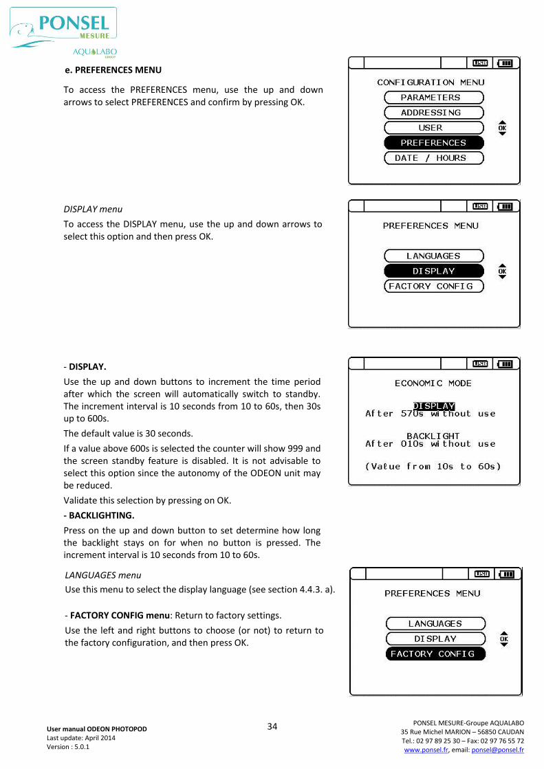
e. PREFERENCES MENU
LANGUAGES menu
Use this menu to select the display language (see section 4.4.3. a).
DISPLAY menu
To access the DISPLAY menu, use the up and down arrows to select this option and then press OK.
To access the PREFERENCES menu, use the up and down arrows to select PREFERENCES and confirm by pressing OK.
- DISPLAY.
Use the up and down buttons to increment the time period after which the screen will automatically switch to standby. The increment interval is 10 seconds from 10 to 60s, then 30s up to 600s.
The default value is 30 seconds.
If a value above 600s is selected the counter will show 999 and the screen standby feature is disabled. It is not advisable to select this option since the autonomy of the ODEON unit may be reduced.
Validate this selection by pressing on OK.
- BACKLIGHTING.
Press on the up and down button to set determine how long the backlight stays on for when no button is pressed. The increment interval is 10 seconds from 10 to 60s.
- FACTORY CONFIG menu: Return to factory settings.
Use the left and right buttons to choose (or not) to return to the factory configuration, and then press OK.
35
PONSEL MESURE-Groupe AQUALABO 35 Rue Michel MARION – 56850 CAUDAN Tel.: 02 97 89 25 30 – Fax: 02 97 76 55 72 www.ponsel.fr, email: [email protected]
User manual ODEON PHOTOPOD Last update: April 2014 Version : 5.0.1
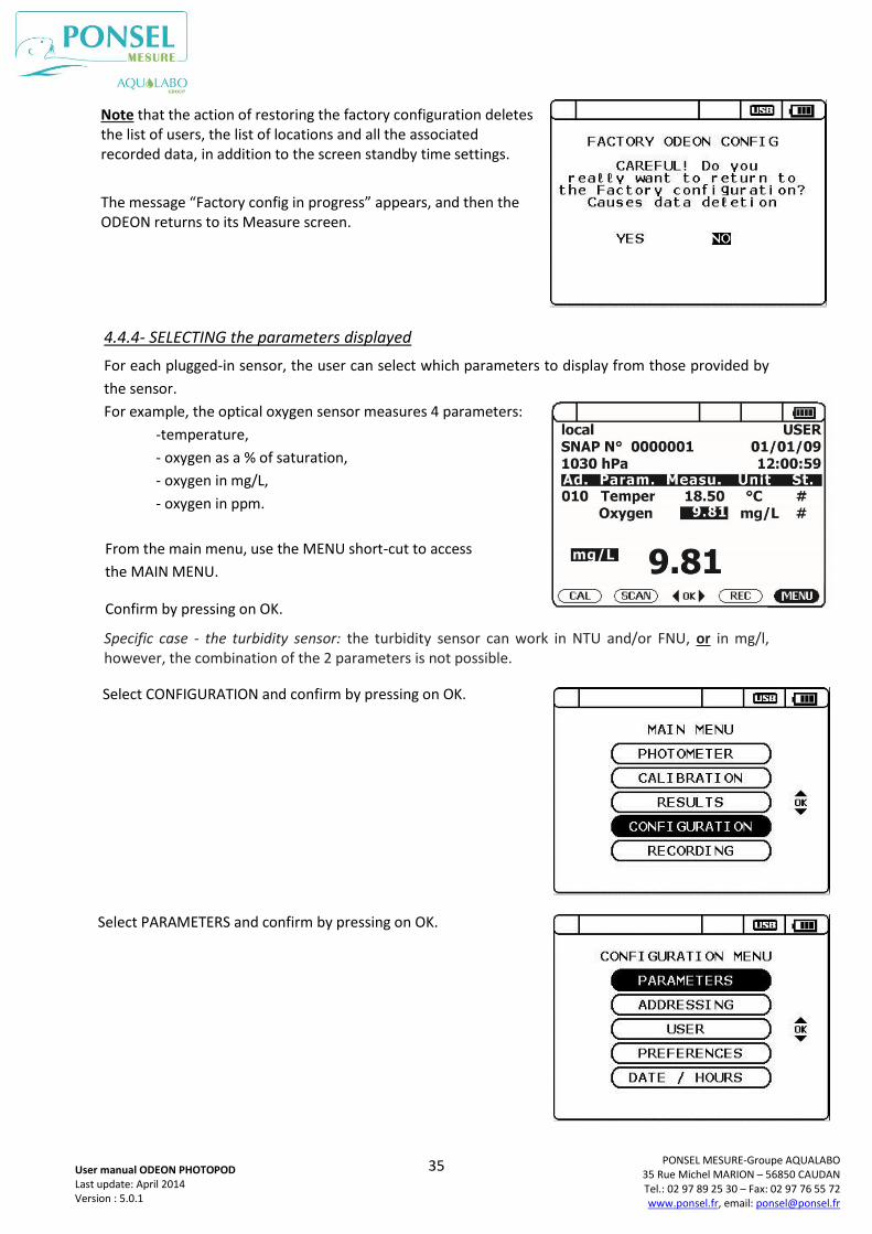
4.4.4- SELECTING the parameters displayed
For each plugged-in sensor, the user can select which parameters to display from those provided by
the sensor.
For example, the optical oxygen sensor measures 4 parameters:
-temperature,
- oxygen as a % of saturation,
- oxygen in mg/L,
- oxygen in ppm.
Specific case - the turbidity sensor: the turbidity sensor can work in NTU and/or FNU, or in mg/l, however, the combination of the 2 parameters is not possible.
From the main menu, use the MENU short-cut to access
the MAIN MENU.
Confirm by pressing on OK.
Select CONFIGURATION and confirm by pressing on OK.
Select PARAMETERS and confirm by pressing on OK.
Note that the action of restoring the factory configuration deletes the list of users, the list of locations and all the associated recorded data, in addition to the screen standby time settings.
The message “Factory config in progress” appears, and then the ODEON returns to its Measure screen.
36
PONSEL MESURE-Groupe AQUALABO 35 Rue Michel MARION – 56850 CAUDAN Tel.: 02 97 89 25 30 – Fax: 02 97 76 55 72 www.ponsel.fr, email: [email protected]
User manual ODEON PHOTOPOD Last update: April 2014 Version : 5.0.1
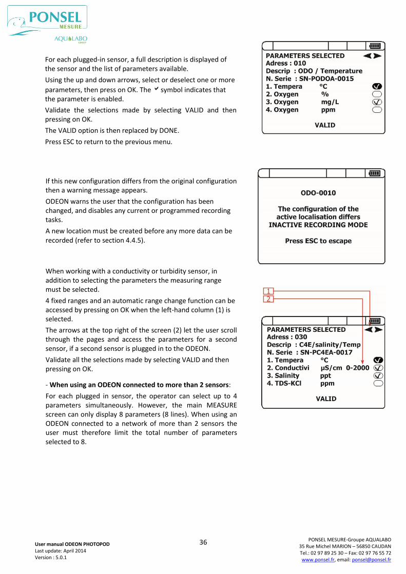
For each plugged-in sensor, a full description is displayed of the sensor and the list of parameters available.
Using the up and down arrows, select or deselect one or more
parameters, then press on OK. The symbol indicates that the parameter is enabled.
Validate the selections made by selecting VALID and then pressing on OK.
The VALID option is then replaced by DONE.
Press ESC to return to the previous menu.
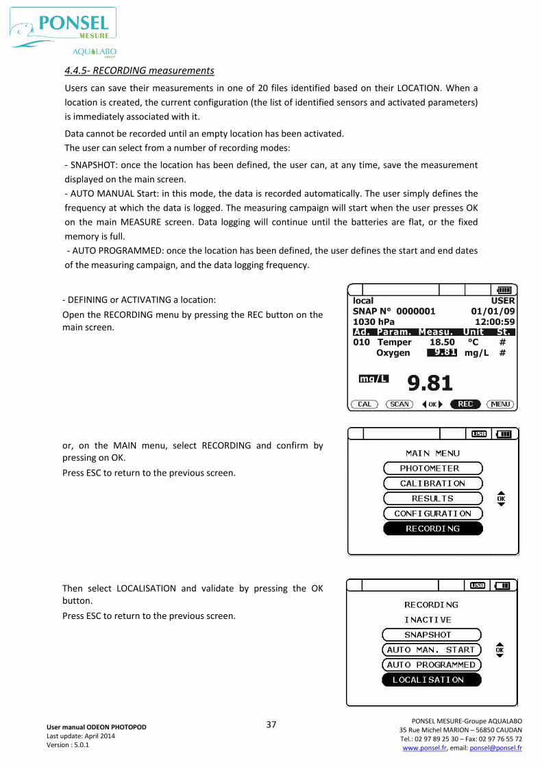
If this new configuration differs from the original configuration then a warning message appears.
ODEON warns the user that the configuration has been changed, and disables any current or programmed recording tasks.
A new location must be created before any more data can be recorded (refer to section 4.4.5).
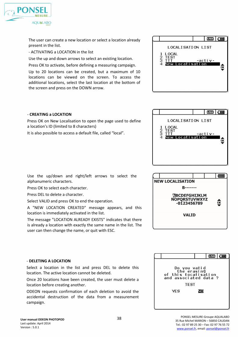
When working with a conductivity or turbidity sensor, in addition to selecting the parameters the measuring range must be selected.
4 fixed ranges and an automatic range change function can be accessed by pressing on OK when the left-hand column (1) is selected.
The arrows at the top right of the screen (2) let the user scroll through the pages and access the parameters for a second sensor, if a second sensor is plugged in to the ODEON.
Validate all the selections made by selecting VALID and then pressing on OK.
Press ESC to return to the previous menu. - When using an ODEON connected to more than 2 sensors:
For each plugged in sensor, the operator can select up to 4 parameters simultaneously. However, the main MEASURE screen can only display 8 parameters (8 lines). When using an ODEON connected to a network of more than 2 sensors the user must therefore limit the total number of parameters selected to 8.
37
PONSEL MESURE-Groupe AQUALABO 35 Rue Michel MARION – 56850 CAUDAN Tel.: 02 97 89 25 30 – Fax: 02 97 76 55 72 www.ponsel.fr, email: [email protected]
User manual ODEON PHOTOPOD Last update: April 2014 Version : 5.0.1
4.4.5- RECORDING measurements
Users can save their measurements in one of 20 files identified based on their LOCATION. When a
location is created, the current configuration (the list of identified sensors and activated parameters)
is immediately associated with it.
Data cannot be recorded until an empty location has been activated.
The user can select from a number of recording modes:
- SNAPSHOT: once the location has been defined, the user can, at any time, save the measurement
displayed on the main screen.
- AUTO MANUAL Start: in this mode, the data is recorded automatically. The user simply defines the
frequency at which the data is logged. The measuring campaign will start when the user presses OK
on the main MEASURE screen. Data logging will continue until the batteries are flat, or the fixed
memory is full.
- AUTO PROGRAMMED: once the location has been defined, the user defines the start and end dates
of the measuring campaign, and the data logging frequency.
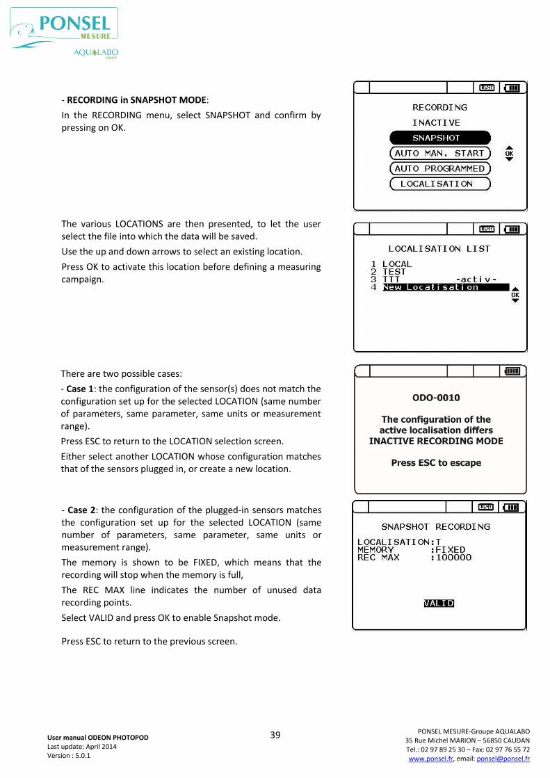
- DEFINING or ACTIVATING a location:
Open the RECORDING menu by pressing the REC button on the main screen.
or, on the MAIN menu, select RECORDING and confirm by pressing on OK.
Press ESC to return to the previous screen.
Then select LOCALISATION and validate by pressing the OK button.
Press ESC to return to the previous screen.
38
PONSEL MESURE-Groupe AQUALABO 35 Rue Michel MARION – 56850 CAUDAN Tel.: 02 97 89 25 30 – Fax: 02 97 76 55 72 www.ponsel.fr, email: [email protected]
User manual ODEON PHOTOPOD Last update: April 2014 Version : 5.0.1
The user can create a new location or select a location already present in the list.
- ACTIVATING a LOCATION in the list
Use the up and down arrows to select an existing location.
Press OK to activate, before defining a measuring campaign.
Up to 20 locations can be created, but a maximum of 10 locations can be viewed on the screen. To access the additional locations, select the last location at the bottom of the screen and press on the DOWN arrow.
- CREATING a LOCATION
Press OK on New Localisation to open the page used to define a location’s ID (limited to 8 characters)
It is also possible to access a default file, called “local”.
Use the up/down and right/left arrows to select the alphanumeric characters.
Press OK to select each character.
Press DEL to delete a character.
Select VALID and press OK to end the operation.
A "NEW LOCATION CREATED" message appears, and this location is immediately activated in the list.
The message "LOCATION ALREADY EXISTS" indicates that there is already a location with exactly the same name in the list. The user can then change the name, or quit with ESC.
- DELETING A LOCATION
Select a location in the list and press DEL to delete this location. The active location cannot be deleted.
Once 20 locations have been created, the user must delete a location before creating another.
ODEON requests confirmation of each deletion to avoid the accidental destruction of the data from a measurement campaign.
39
PONSEL MESURE-Groupe AQUALABO 35 Rue Michel MARION – 56850 CAUDAN Tel.: 02 97 89 25 30 – Fax: 02 97 76 55 72 www.ponsel.fr, email: [email protected]
User manual ODEON PHOTOPOD Last update: April 2014 Version : 5.0.1
- RECORDING in SNAPSHOT MODE:
In the RECORDING menu, select SNAPSHOT and confirm by pressing on OK.
The various LOCATIONS are then presented, to let the user select the file into which the data will be saved.
Use the up and down arrows to select an existing location.
Press OK to activate this location before defining a measuring campaign.
There are two possible cases:
- Case 1: the configuration of the sensor(s) does not match the configuration set up for the selected LOCATION (same number of parameters, same parameter, same units or measurement range).
Press ESC to return to the LOCATION selection screen.
Either select another LOCATION whose configuration matches that of the sensors plugged in, or create a new location.
- Case 2: the configuration of the plugged-in sensors matches the configuration set up for the selected LOCATION (same number of parameters, same parameter, same units or measurement range).
The memory is shown to be FIXED, which means that the recording will stop when the memory is full,
The REC MAX line indicates the number of unused data recording points.
Select VALID and press OK to enable Snapshot mode.
Press ESC to return to the previous screen.
40
PONSEL MESURE-Groupe AQUALABO 35 Rue Michel MARION – 56850 CAUDAN Tel.: 02 97 89 25 30 – Fax: 02 97 76 55 72 www.ponsel.fr, email: [email protected]
User manual ODEON PHOTOPOD Last update: April 2014 Version : 5.0.1
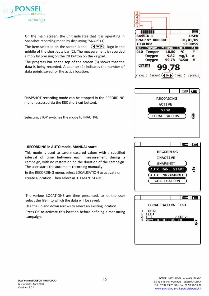
SNAPSHOT recording mode can be stopped in the RECORDING menu (accessed via the REC short-cut button).
Selecting STOP switches the mode to INACTIVE
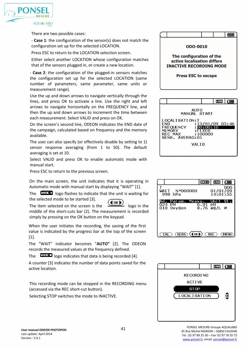
- RECORDING in AUTO mode, MANUAL start:
This mode is used to save measured values with a specified interval of time between each measurement during a campaign, with no restriction on the duration of the campaign. The user starts the automatic recording manually.
In the RECORDING menu, select LOCALISATION to activate or
create a location. Then select AUTO MAN. START.
The various LOCATIONS are then presented, to let the user select the file into which the data will be saved.
Use the up and down arrows to select an existing location.
Press OK to activate this location before defining a measuring campaign.
On the main screen, the unit indicates that it is operating in Snapshot recording mode by displaying “SNAP” (1).
The item selected on the screen is the logo in the middle of the short-cuts bar (2). The measurement is recorded simply by pressing on the OK button on the keypad.
The progress bar at the top of the screen (3) shows that the data is being recorded. A counter (4) indicates the number of data points saved for the active location.
41
PONSEL MESURE-Groupe AQUALABO 35 Rue Michel MARION – 56850 CAUDAN Tel.: 02 97 89 25 30 – Fax: 02 97 76 55 72 www.ponsel.fr, email: [email protected]
User manual ODEON PHOTOPOD Last update: April 2014 Version : 5.0.1
There are two possible cases:
- Case 1: the configuration of the sensor(s) does not match the configuration set up for the selected LOCATION.
Press ESC to return to the LOCATION selection screen.
Either select another LOCATION whose configuration matches that of the sensors plugged in, or create a new location.
- Case 2: the configuration of the plugged-in sensors matches the configuration set up for the selected LOCATION (same number of parameters, same parameter, same units or measurement range).
Use the up and down arrows to navigate vertically through the lines, and press OK to activate a line. Use the right and left arrows to navigate horizontally on the FREQUENCY line, and then the up and down arrows to increment the time between each measurement. Select VALID and press on OK.
On the screen’s second line, ODEON indicates the END date of the campaign, calculated based on frequency and the memory available.
The user can also specify (or effectively disable by setting to 1) sensor response averaging (from 1 to 50). The default averaging is set at 10.
Select VALID and press OK to enable automatic mode with manual start.
Press ESC to return to the previous screen.
On the main screen, the unit indicates that it is operating in Automatic mode with manual start by displaying “WAIT” [1].
The logo flashes to indicate that the unit is waiting for the selected mode to be started [3].
The item selected on the screen is the logo in the middle of the short-cuts bar (2). The measurement is recorded simply by pressing on the OK button on the keypad.
When the user initiates the recording, the saving of the first value is indicated by the progress bar at the top of the screen [1].
The “WAIT” indicator becomes “AUTO” [2]. The ODEON records the measured values at the frequency defined.
The logo indicates that data is being recorded [4].
A counter [3] indicates the number of data points saved for the active location.
This recording mode can be stopped in the RECORDING menu (accessed via the REC short-cut button).
Selecting STOP switches the mode to INACTIVE.
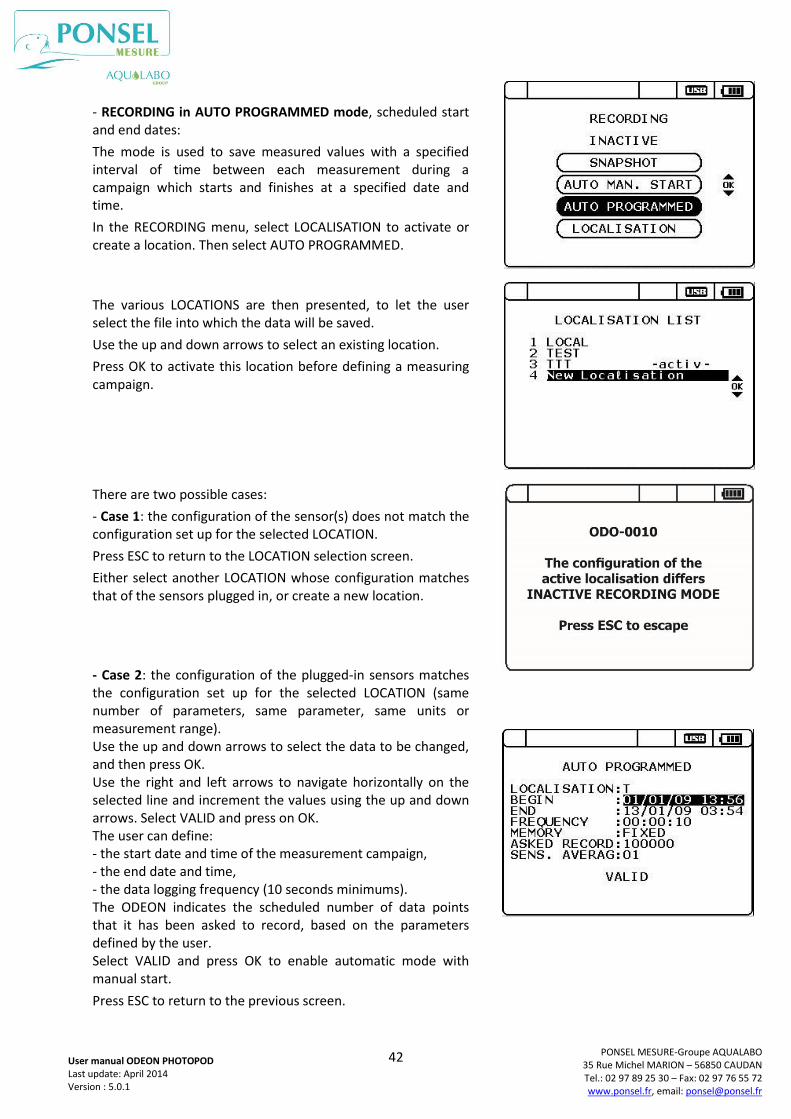
42
PONSEL MESURE-Groupe AQUALABO 35 Rue Michel MARION – 56850 CAUDAN Tel.: 02 97 89 25 30 – Fax: 02 97 76 55 72 www.ponsel.fr, email: [email protected]
User manual ODEON PHOTOPOD Last update: April 2014 Version : 5.0.1
- RECORDING in AUTO PROGRAMMED mode, scheduled start and end dates:
The mode is used to save measured values with a specified interval of time between each measurement during a campaign which starts and finishes at a specified date and time.
In the RECORDING menu, select LOCALISATION to activate or create a location. Then select AUTO PROGRAMMED.
The various LOCATIONS are then presented, to let the user select the file into which the data will be saved.
Use the up and down arrows to select an existing location.
Press OK to activate this location before defining a measuring campaign.
There are two possible cases:
- Case 1: the configuration of the sensor(s) does not match the configuration set up for the selected LOCATION.
Press ESC to return to the LOCATION selection screen.
Either select another LOCATION whose configuration matches that of the sensors plugged in, or create a new location.
- Case 2: the configuration of the plugged-in sensors matches the configuration set up for the selected LOCATION (same number of parameters, same parameter, same units or measurement range). Use the up and down arrows to select the data to be changed, and then press OK. Use the right and left arrows to navigate horizontally on the selected line and increment the values using the up and down arrows. Select VALID and press on OK. The user can define: - the start date and time of the measurement campaign, - the end date and time, - the data logging frequency (10 seconds minimums). The ODEON indicates the scheduled number of data points that it has been asked to record, based on the parameters defined by the user. Select VALID and press OK to enable automatic mode with manual start.
Press ESC to return to the previous screen.
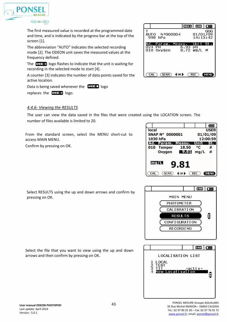
43
PONSEL MESURE-Groupe AQUALABO 35 Rue Michel MARION – 56850 CAUDAN Tel.: 02 97 89 25 30 – Fax: 02 97 76 55 72 www.ponsel.fr, email: [email protected]
User manual ODEON PHOTOPOD Last update: April 2014 Version : 5.0.1
4.4.6- Viewing the RESULTS
The user can view the data saved in the files that were created using the LOCATION screen. The
number of files available is limited to 20.
From the standard screen, select the MENU short-cut to access MAIN MENU.
Confirm by pressing on OK.
Select RESULTS using the up and down arrows and confirm by pressing on OK.
Select the file that you want to view using the up and down arrows and then confirm by pressing on OK.
The first measured value is recorded at the programmed date and time, and is indicated by the progress bar at the top of the screen [1].
The abbreviation “AUTO” indicates the selected recording mode [2]. The ODEON unit saves the measured values at the frequency defined.
The logo flashes to indicate that the unit is waiting for recording in the selected mode to start [4].
A counter [3] indicates the number of data points saved for the active location.
Data is being saved whenever the logo
replaces the logo.
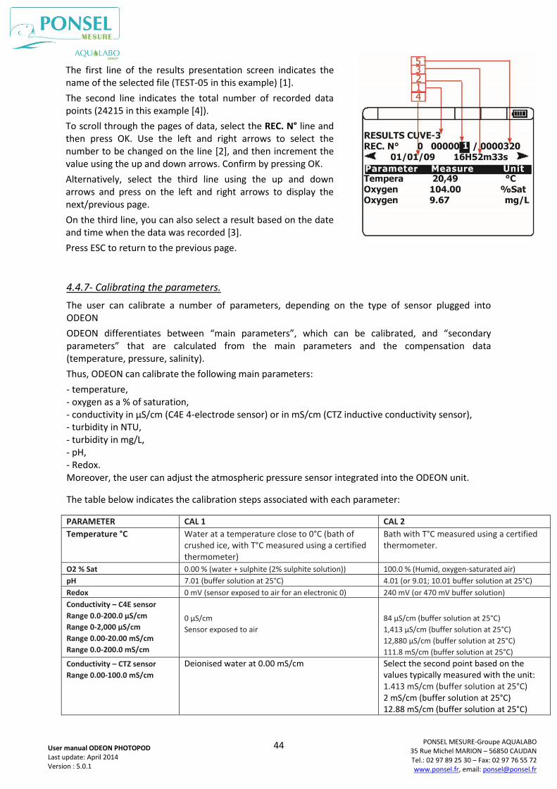
44
PONSEL MESURE-Groupe AQUALABO 35 Rue Michel MARION – 56850 CAUDAN Tel.: 02 97 89 25 30 – Fax: 02 97 76 55 72 www.ponsel.fr, email: [email protected]
User manual ODEON PHOTOPOD Last update: April 2014 Version : 5.0.1
4.4.7- Calibrating the parameters.
The user can calibrate a number of parameters, depending on the type of sensor plugged into ODEON
ODEON differentiates between “main parameters”, which can be calibrated, and “secondary parameters” that are calculated from the main parameters and the compensation data (temperature, pressure, salinity).
Thus, ODEON can calibrate the following main parameters:
- temperature, - oxygen as a % of saturation, - conductivity in µS/cm (C4E 4-electrode sensor) or in mS/cm (CTZ inductive conductivity sensor), - turbidity in NTU, - turbidity in mg/L, - pH, - Redox. Moreover, the user can adjust the atmospheric pressure sensor integrated into the ODEON unit.
The table below indicates the calibration steps associated with each parameter:
PARAMETER CAL 1 CAL 2
Temperature °C Water at a temperature close to 0°C (bath of crushed ice, with T°C measured using a certified thermometer)
Bath with T°C measured using a certified thermometer.
O2 % Sat 0.00 % (water + sulphite (2% sulphite solution)) 100.0 % (Humid, oxygen-saturated air)
pH 7.01 (buffer solution at 25°C) 4.01 (or 9.01; 10.01 buffer solution at 25°C)
Redox 0 mV (sensor exposed to air for an electronic 0) 240 mV (or 470 mV buffer solution)
Conductivity – C4E sensor
Range 0.0-200.0 µS/cm
Range 0-2,000 µS/cm
Range 0.00-20.00 mS/cm
Range 0.0-200.0 mS/cm
0 µS/cm
Sensor exposed to air
84 µS/cm (buffer solution at 25°C)
1,413 µS/cm (buffer solution at 25°C)
12,880 µS/cm (buffer solution at 25°C)
111.8 mS/cm (buffer solution at 25°C)
Conductivity – CTZ sensor
Range 0.00-100.0 mS/cm
Deionised water at 0.00 mS/cm Select the second point based on the values typically measured with the unit: 1.413 mS/cm (buffer solution at 25°C) 2 mS/cm (buffer solution at 25°C) 12.88 mS/cm (buffer solution at 25°C)
The first line of the results presentation screen indicates the name of the selected file (TEST-05 in this example) [1].
The second line indicates the total number of recorded data points (24215 in this example [4]).
To scroll through the pages of data, select the REC. N° line and then press OK. Use the left and right arrows to select the number to be changed on the line [2], and then increment the value using the up and down arrows. Confirm by pressing OK.
Alternatively, select the third line using the up and down arrows and press on the left and right arrows to display the next/previous page.
On the third line, you can also select a result based on the date and time when the data was recorded [3].
Press ESC to return to the previous page.
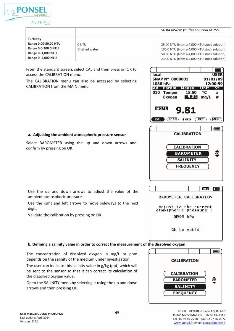
45
PONSEL MESURE-Groupe AQUALABO 35 Rue Michel MARION – 56850 CAUDAN Tel.: 02 97 89 25 30 – Fax: 02 97 76 55 72 www.ponsel.fr, email: [email protected]
User manual ODEON PHOTOPOD Last update: April 2014 Version : 5.0.1
56.84 mS/cm (buffer solution at 25°C)
Turbidity
Range 0.00-50.00 NTU
Range 0.0-200.0 NTU
Range 0 -1,000 NTU
Range 0 -4,000 NTU
0 NTU
Distilled water
25.00 NTU (from a 4,000 NTU stock solution)
100.0 NTU (from a 4,000 NTU stock solution)
500.0 NTU (from a 4,000 NTU stock solution)
2,000 NTU (from a 4,000 NTU stock solution)
a. Adjusting the ambient atmospheric pressure sensor
b. Defining a salinity value in order to correct the measurement of the dissolved oxygen:
From the standard screen, select CAL and then press on OK to access the CALIBRATION menu.
The CALIBRATION menu can also be accessed by selecting CALIBRATION from the MAIN menu
Select BAROMETER using the up and down arrows and confirm by pressing on OK.
Use the up and down arrows to adjust the value of the ambient atmospheric pressure.
Use the right and left arrows to move sideways to the next digit.
Validate the calibration by pressing on OK.
ESC pour revenir au menu précédent
The concentration of dissolved oxygen in mg/L or ppm depends on the salinity of the medium under investigation.
The user can indicate this salinity value in g/kg (ppt) which will be sent to the sensor so that it can correct its calculation of the dissolved oxygen value.
Open the SALINITY menu by selecting it using the up and down arrows and then pressing OK.
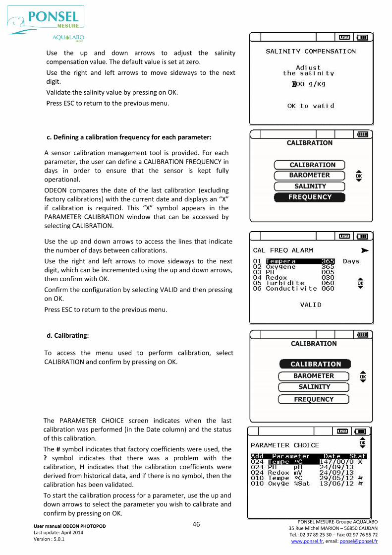
46
PONSEL MESURE-Groupe AQUALABO 35 Rue Michel MARION – 56850 CAUDAN Tel.: 02 97 89 25 30 – Fax: 02 97 76 55 72 www.ponsel.fr, email: [email protected]
User manual ODEON PHOTOPOD Last update: April 2014 Version : 5.0.1
c. Defining a calibration frequency for each parameter:
d. Calibrating:
Use the up and down arrows to adjust the salinity compensation value. The default value is set at zero.
Use the right and left arrows to move sideways to the next digit.
Validate the salinity value by pressing on OK.
Press ESC to return to the previous menu.
A sensor calibration management tool is provided. For each parameter, the user can define a CALIBRATION FREQUENCY in days in order to ensure that the sensor is kept fully operational.
ODEON compares the date of the last calibration (excluding factory calibrations) with the current date and displays an “X” if calibration is required. This “X” symbol appears in the PARAMETER CALIBRATION window that can be accessed by selecting CALIBRATION.
Use the up and down arrows to access the lines that indicate the number of days between calibrations.
Use the right and left arrows to move sideways to the next digit, which can be incremented using the up and down arrows, then confirm with OK.
Confirm the configuration by selecting VALID and then pressing on OK.
Press ESC to return to the previous menu.
To access the menu used to perform calibration, select CALIBRATION and confirm by pressing on OK.
The PARAMETER CHOICE screen indicates when the last calibration was performed (in the Date column) and the status of this calibration.
The # symbol indicates that factory coefficients were used, the ? symbol indicates that there was a problem with the calibration, H indicates that the calibration coefficients were derived from historical data, and if there is no symbol, then the calibration has been validated.
To start the calibration process for a parameter, use the up and down arrows to select the parameter you wish to calibrate and confirm by pressing on OK.
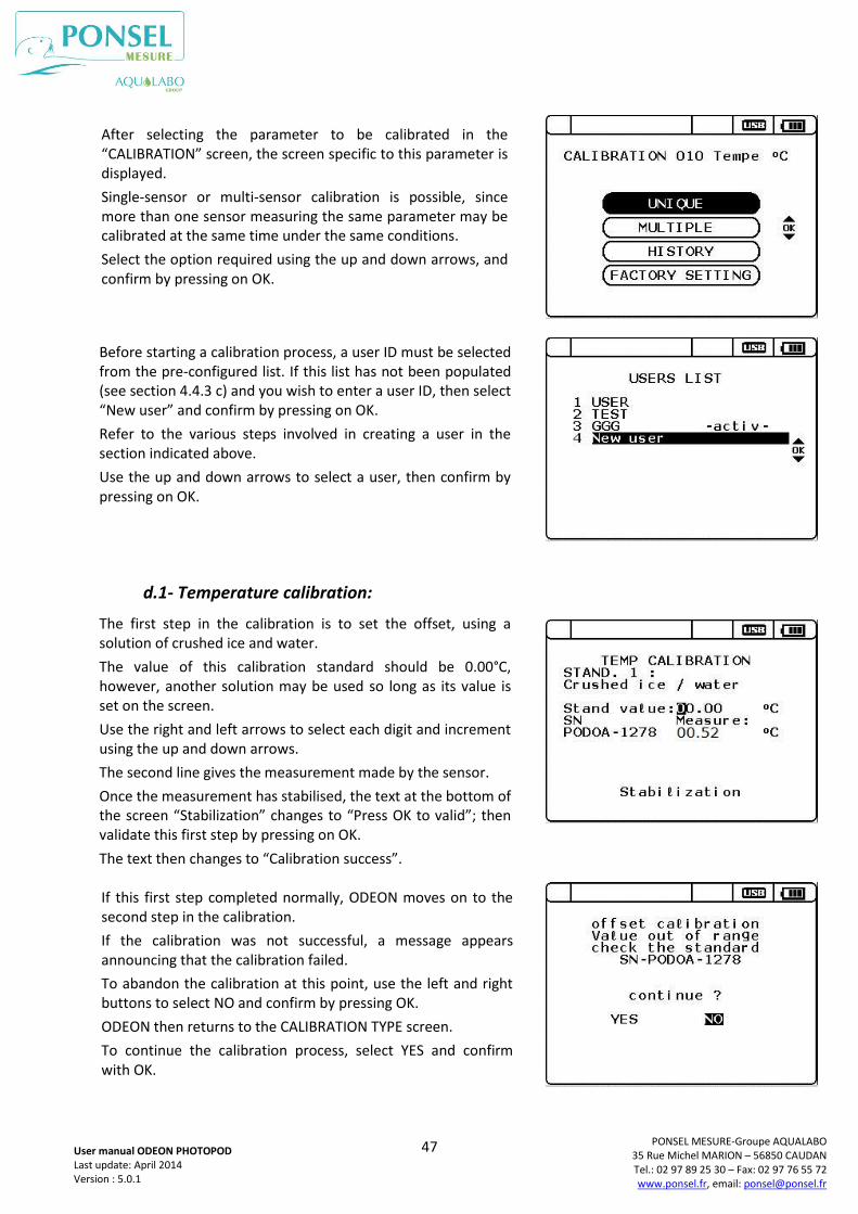
47
PONSEL MESURE-Groupe AQUALABO 35 Rue Michel MARION – 56850 CAUDAN Tel.: 02 97 89 25 30 – Fax: 02 97 76 55 72 www.ponsel.fr, email: [email protected]
User manual ODEON PHOTOPOD Last update: April 2014 Version : 5.0.1
d.1- Temperature calibration:
After selecting the parameter to be calibrated in the “CALIBRATION” screen, the screen specific to this parameter is displayed.
Single-sensor or multi-sensor calibration is possible, since more than one sensor measuring the same parameter may be calibrated at the same time under the same conditions.
Select the option required using the up and down arrows, and confirm by pressing on OK.
Before starting a calibration process, a user ID must be selected from the pre-configured list. If this list has not been populated (see section 4.4.3 c) and you wish to enter a user ID, then select “New user” and confirm by pressing on OK.
Refer to the various steps involved in creating a user in the section indicated above.
Use the up and down arrows to select a user, then confirm by pressing on OK.
The first step in the calibration is to set the offset, using a solution of crushed ice and water.
The value of this calibration standard should be 0.00°C, however, another solution may be used so long as its value is set on the screen.
Use the right and left arrows to select each digit and increment using the up and down arrows.
The second line gives the measurement made by the sensor.
Once the measurement has stabilised, the text at the bottom of the screen “Stabilization” changes to “Press OK to valid”; then validate this first step by pressing on OK.
The text then changes to “Calibration success”.
If this first step completed normally, ODEON moves on to the second step in the calibration.
If the calibration was not successful, a message appears announcing that the calibration failed.
To abandon the calibration at this point, use the left and right buttons to select NO and confirm by pressing OK.
ODEON then returns to the CALIBRATION TYPE screen.
To continue the calibration process, select YES and confirm with OK.
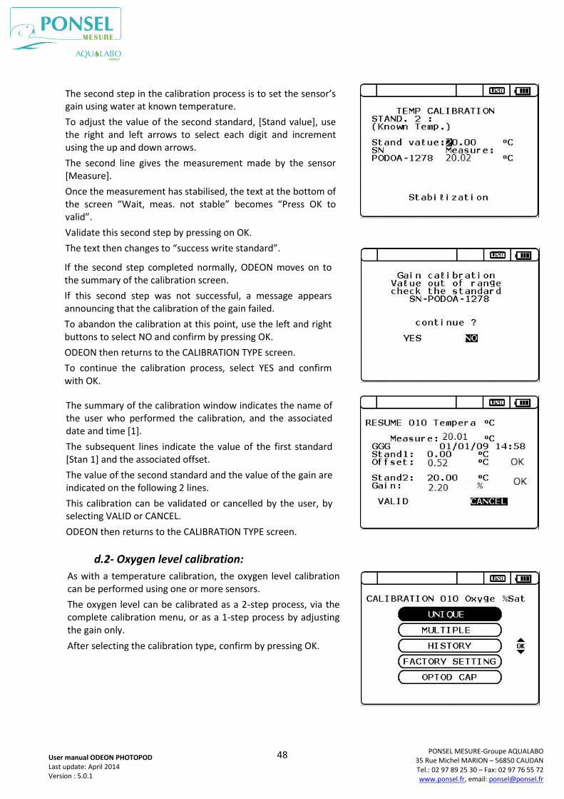
48
PONSEL MESURE-Groupe AQUALABO 35 Rue Michel MARION – 56850 CAUDAN Tel.: 02 97 89 25 30 – Fax: 02 97 76 55 72 www.ponsel.fr, email: [email protected]
User manual ODEON PHOTOPOD Last update: April 2014 Version : 5.0.1
d.2- Oxygen level calibration:
The second step in the calibration process is to set the sensor’s gain using water at known temperature.
To adjust the value of the second standard, [Stand value], use the right and left arrows to select each digit and increment using the up and down arrows.
The second line gives the measurement made by the sensor [Measure].
Once the measurement has stabilised, the text at the bottom of the screen “Wait, meas. not stable” becomes “Press OK to valid”.
Validate this second step by pressing on OK.
The text then changes to “success write standard”.
If the second step completed normally, ODEON moves on to the summary of the calibration screen.
If this second step was not successful, a message appears announcing that the calibration of the gain failed.
To abandon the calibration at this point, use the left and right buttons to select NO and confirm by pressing OK.
ODEON then returns to the CALIBRATION TYPE screen.
To continue the calibration process, select YES and confirm with OK.
The summary of the calibration window indicates the name of the user who performed the calibration, and the associated date and time [1].
The subsequent lines indicate the value of the first standard [Stan 1] and the associated offset.
The value of the second standard and the value of the gain are indicated on the following 2 lines.
This calibration can be validated or cancelled by the user, by selecting VALID or CANCEL.
ODEON then returns to the CALIBRATION TYPE screen.
As with a temperature calibration, the oxygen level calibration can be performed using one or more sensors.
The oxygen level can be calibrated as a 2-step process, via the complete calibration menu, or as a 1-step process by adjusting the gain only.
After selecting the calibration type, confirm by pressing OK.
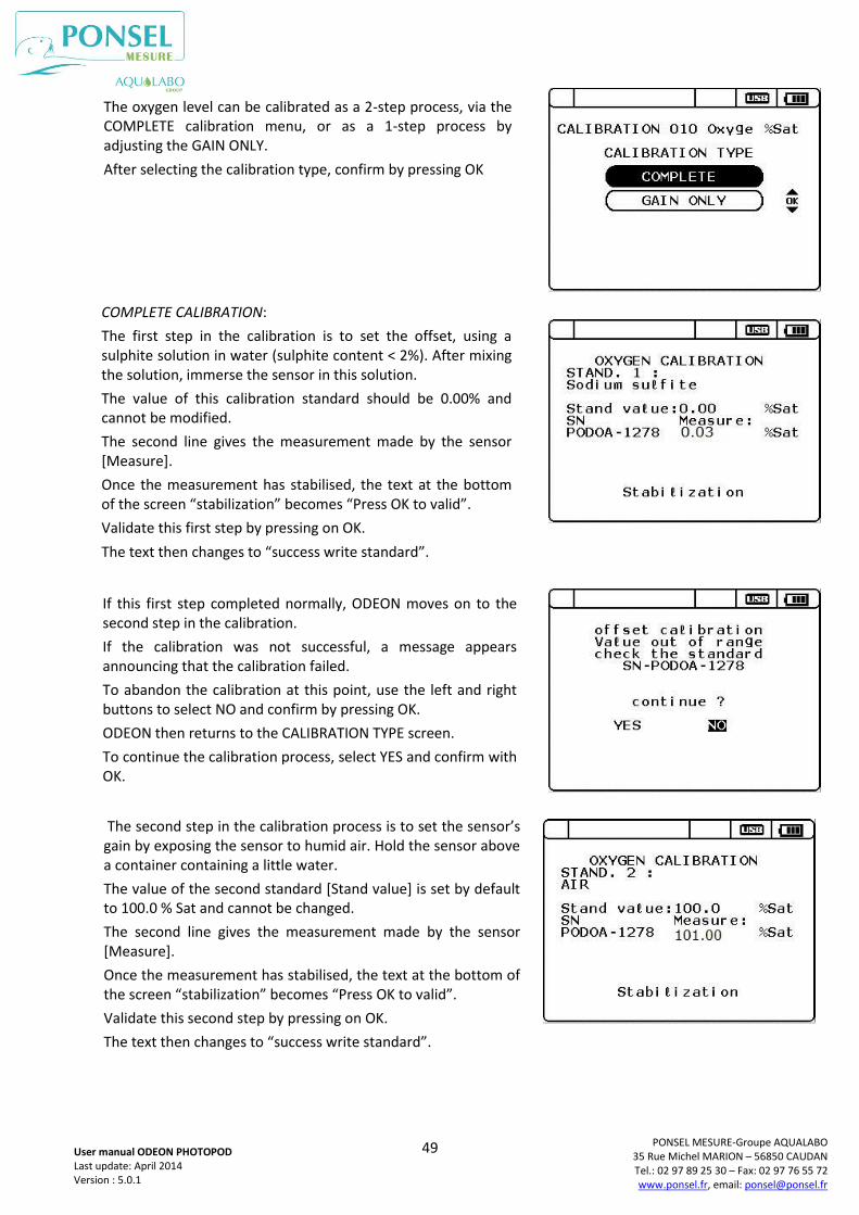
49
PONSEL MESURE-Groupe AQUALABO 35 Rue Michel MARION – 56850 CAUDAN Tel.: 02 97 89 25 30 – Fax: 02 97 76 55 72 www.ponsel.fr, email: [email protected]
User manual ODEON PHOTOPOD Last update: April 2014 Version : 5.0.1
COMPLETE CALIBRATION:
The first step in the calibration is to set the offset, using a sulphite solution in water (sulphite content < 2%). After mixing the solution, immerse the sensor in this solution.
The value of this calibration standard should be 0.00% and cannot be modified.
The second line gives the measurement made by the sensor [Measure].
Once the measurement has stabilised, the text at the bottom of the screen “stabilization” becomes “Press OK to valid”.
Validate this first step by pressing on OK.
The text then changes to “success write standard”.
If this first step completed normally, ODEON moves on to the second step in the calibration.
If the calibration was not successful, a message appears announcing that the calibration failed.
To abandon the calibration at this point, use the left and right buttons to select NO and confirm by pressing OK.
ODEON then returns to the CALIBRATION TYPE screen.
To continue the calibration process, select YES and confirm with OK.
The second step in the calibration process is to set the sensor’s gain by exposing the sensor to humid air. Hold the sensor above a container containing a little water.
The value of the second standard [Stand value] is set by default to 100.0 % Sat and cannot be changed.
The second line gives the measurement made by the sensor [Measure].
Once the measurement has stabilised, the text at the bottom of the screen “stabilization” becomes “Press OK to valid”.
Validate this second step by pressing on OK.
The text then changes to “success write standard”.
The oxygen level can be calibrated as a 2-step process, via the COMPLETE calibration menu, or as a 1-step process by adjusting the GAIN ONLY.
After selecting the calibration type, confirm by pressing OK
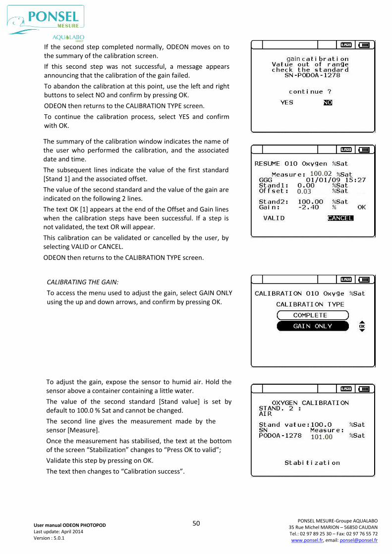
50
PONSEL MESURE-Groupe AQUALABO 35 Rue Michel MARION – 56850 CAUDAN Tel.: 02 97 89 25 30 – Fax: 02 97 76 55 72 www.ponsel.fr, email: [email protected]
User manual ODEON PHOTOPOD Last update: April 2014 Version : 5.0.1
If the second step completed normally, ODEON moves on to the summary of the calibration screen.
If this second step was not successful, a message appears announcing that the calibration of the gain failed.
To abandon the calibration at this point, use the left and right buttons to select NO and confirm by pressing OK.
ODEON then returns to the CALIBRATION TYPE screen.
To continue the calibration process, select YES and confirm with OK.
The summary of the calibration window indicates the name of the user who performed the calibration, and the associated date and time.
The subsequent lines indicate the value of the first standard [Stand 1] and the associated offset.
The value of the second standard and the value of the gain are indicated on the following 2 lines.
The text OK [1] appears at the end of the Offset and Gain lines when the calibration steps have been successful. If a step is not validated, the text OR will appear.
This calibration can be validated or cancelled by the user, by selecting VALID or CANCEL.
ODEON then returns to the CALIBRATION TYPE screen.
CALIBRATING THE GAIN:
To access the menu used to adjust the gain, select GAIN ONLY using the up and down arrows, and confirm by pressing OK.
To adjust the gain, expose the sensor to humid air. Hold the sensor above a container containing a little water.
The value of the second standard [Stand value] is set by default to 100.0 % Sat and cannot be changed.
The second line gives the measurement made by the sensor [Measure].
Once the measurement has stabilised, the text at the bottom of the screen “Stabilization” changes to “Press OK to valid”;
Validate this step by pressing on OK.
The text then changes to “Calibration success”.
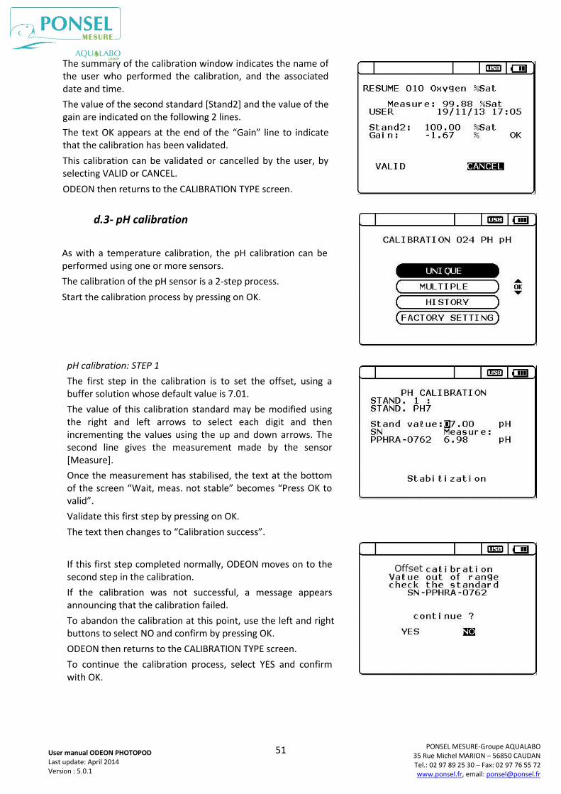
51
PONSEL MESURE-Groupe AQUALABO 35 Rue Michel MARION – 56850 CAUDAN Tel.: 02 97 89 25 30 – Fax: 02 97 76 55 72 www.ponsel.fr, email: [email protected]
User manual ODEON PHOTOPOD Last update: April 2014 Version : 5.0.1
d.3- pH calibration
The summary of the calibration window indicates the name of the user who performed the calibration, and the associated date and time.
The value of the second standard [Stand2] and the value of the gain are indicated on the following 2 lines.
The text OK appears at the end of the “Gain” line to indicate that the calibration has been validated.
This calibration can be validated or cancelled by the user, by selecting VALID or CANCEL.
ODEON then returns to the CALIBRATION TYPE screen.
As with a temperature calibration, the pH calibration can be performed using one or more sensors.
The calibration of the pH sensor is a 2-step process.
Start the calibration process by pressing on OK.
pH calibration: STEP 1
The first step in the calibration is to set the offset, using a buffer solution whose default value is 7.01.
The value of this calibration standard may be modified using the right and left arrows to select each digit and then incrementing the values using the up and down arrows. The second line gives the measurement made by the sensor [Measure].
Once the measurement has stabilised, the text at the bottom of the screen “Wait, meas. not stable” becomes “Press OK to valid”.
Validate this first step by pressing on OK.
The text then changes to “Calibration success”.
If this first step completed normally, ODEON moves on to the second step in the calibration.
If the calibration was not successful, a message appears announcing that the calibration failed.
To abandon the calibration at this point, use the left and right buttons to select NO and confirm by pressing OK.
ODEON then returns to the CALIBRATION TYPE screen.
To continue the calibration process, select YES and confirm with OK.
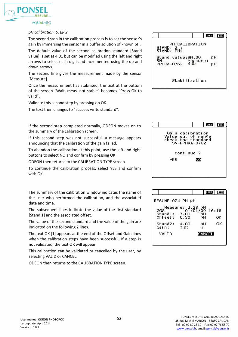
52
PONSEL MESURE-Groupe AQUALABO 35 Rue Michel MARION – 56850 CAUDAN Tel.: 02 97 89 25 30 – Fax: 02 97 76 55 72 www.ponsel.fr, email: [email protected]
User manual ODEON PHOTOPOD Last update: April 2014 Version : 5.0.1
pH calibration: STEP 2
The second step in the calibration process is to set the sensor’s gain by immersing the sensor in a buffer solution of known pH.
The default value of the second calibration standard [Stand value] is set at 4.01 but can be modified using the left and right arrows to select each digit and incremented using the up and down arrows.
The second line gives the measurement made by the sensor [Measure].
Once the measurement has stabilised, the text at the bottom of the screen “Wait, meas. not stable” becomes “Press OK to valid”.
Validate this second step by pressing on OK.
The text then changes to “success write standard”.
If the second step completed normally, ODEON moves on to the summary of the calibration screen.
If this second step was not successful, a message appears announcing that the calibration of the gain failed.
To abandon the calibration at this point, use the left and right buttons to select NO and confirm by pressing OK.
ODEON then returns to the CALIBRATION TYPE screen.
To continue the calibration process, select YES and confirm with OK.
The summary of the calibration window indicates the name of the user who performed the calibration, and the associated date and time.
The subsequent lines indicate the value of the first standard [Stand 1] and the associated offset.
The value of the second standard and the value of the gain are indicated on the following 2 lines.
The text OK [1] appears at the end of the Offset and Gain lines when the calibration steps have been successful. If a step is not validated, the text OR will appear.
This calibration can be validated or cancelled by the user, by selecting VALID or CANCEL.
ODEON then returns to the CALIBRATION TYPE screen.
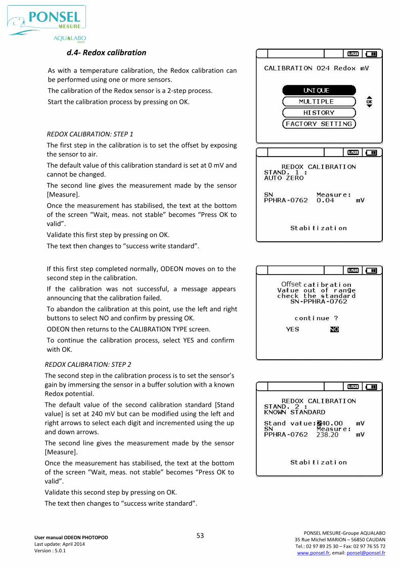
53
PONSEL MESURE-Groupe AQUALABO 35 Rue Michel MARION – 56850 CAUDAN Tel.: 02 97 89 25 30 – Fax: 02 97 76 55 72 www.ponsel.fr, email: [email protected]
User manual ODEON PHOTOPOD Last update: April 2014 Version : 5.0.1
d.4- Redox calibration
As with a temperature calibration, the Redox calibration can be performed using one or more sensors.
The calibration of the Redox sensor is a 2-step process.
Start the calibration process by pressing on OK.
REDOX CALIBRATION: STEP 1
The first step in the calibration is to set the offset by exposing the sensor to air.
The default value of this calibration standard is set at 0 mV and cannot be changed.
The second line gives the measurement made by the sensor [Measure].
Once the measurement has stabilised, the text at the bottom of the screen “Wait, meas. not stable” becomes “Press OK to valid”.
Validate this first step by pressing on OK.
The text then changes to “success write standard”.
If this first step completed normally, ODEON moves on to the second step in the calibration.
If the calibration was not successful, a message appears announcing that the calibration failed.
To abandon the calibration at this point, use the left and right buttons to select NO and confirm by pressing OK.
ODEON then returns to the CALIBRATION TYPE screen.
To continue the calibration process, select YES and confirm with OK.
REDOX CALIBRATION: STEP 2
The second step in the calibration process is to set the sensor’s gain by immersing the sensor in a buffer solution with a known Redox potential.
The default value of the second calibration standard [Stand value] is set at 240 mV but can be modified using the left and right arrows to select each digit and incremented using the up and down arrows.
The second line gives the measurement made by the sensor [Measure].
Once the measurement has stabilised, the text at the bottom of the screen “Wait, meas. not stable” becomes “Press OK to valid”.
Validate this second step by pressing on OK.
The text then changes to “success write standard”.
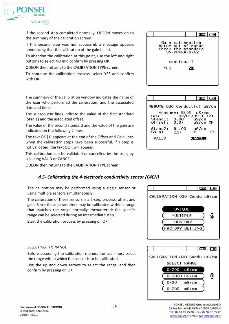
54
PONSEL MESURE-Groupe AQUALABO 35 Rue Michel MARION – 56850 CAUDAN Tel.: 02 97 89 25 30 – Fax: 02 97 76 55 72 www.ponsel.fr, email: [email protected]
User manual ODEON PHOTOPOD Last update: April 2014 Version : 5.0.1
d.5- Calibrating the 4-electrode conductivity sensor (C4EN)
If the second step completed normally, ODEON moves on to the summary of the calibration screen.
If this second step was not successful, a message appears announcing that the calibration of the gain failed.
To abandon the calibration at this point, use the left and right buttons to select NO and confirm by pressing OK.
ODEON then returns to the CALIBRATION TYPE screen.
To continue the calibration process, select YES and confirm with OK.
The summary of the calibration window indicates the name of the user who performed the calibration, and the associated date and time.
The subsequent lines indicate the value of the first standard [Stan 1] and the associated offset.
The value of the second standard and the value of the gain are indicated on the following 2 lines.
The text OK [1] appears at the end of the Offset and Gain lines when the calibration steps have been successful. If a step is not validated, the text OOR will appear.
This calibration can be validated or cancelled by the user, by selecting VALID or CANCEL.
ODEON then returns to the CALIBRATION TYPE screen.
The calibration may be performed using a single sensor or using multiple sensors simultaneously.
The calibration of these sensors is a 2-step process: offset and gain. Since these parameters may be calibrated within a range that matches the range normally encountered; the specific range can be selected during an intermediate step.
Start the calibration process by pressing on OK.
SELECTING THE RANGE
Before accessing the calibration menus, the user must select the range within which the sensor is to be calibrated.
Use the up and down arrows to select the range, and then confirm by pressing on OK
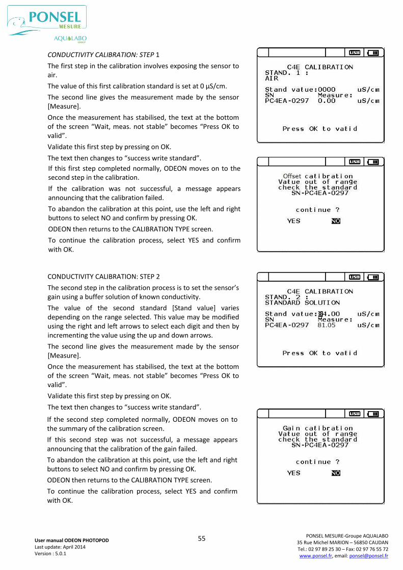
55
PONSEL MESURE-Groupe AQUALABO 35 Rue Michel MARION – 56850 CAUDAN Tel.: 02 97 89 25 30 – Fax: 02 97 76 55 72 www.ponsel.fr, email: [email protected]
User manual ODEON PHOTOPOD Last update: April 2014 Version : 5.0.1
CONDUCTIVITY CALIBRATION: STEP 1
The first step in the calibration involves exposing the sensor to air.
The value of this first calibration standard is set at 0 µS/cm.
The second line gives the measurement made by the sensor [Measure].
Once the measurement has stabilised, the text at the bottom of the screen “Wait, meas. not stable” becomes “Press OK to valid”.
Validate this first step by pressing on OK.
The text then changes to “success write standard”.
If this first step completed normally, ODEON moves on to the second step in the calibration.
If the calibration was not successful, a message appears announcing that the calibration failed.
To abandon the calibration at this point, use the left and right buttons to select NO and confirm by pressing OK.
ODEON then returns to the CALIBRATION TYPE screen.
To continue the calibration process, select YES and confirm with OK.
CONDUCTIVITY CALIBRATION: STEP 2
The second step in the calibration process is to set the sensor’s gain using a buffer solution of known conductivity.
The value of the second standard [Stand value] varies depending on the range selected. This value may be modified using the right and left arrows to select each digit and then by incrementing the value using the up and down arrows.
The second line gives the measurement made by the sensor [Measure].
Once the measurement has stabilised, the text at the bottom of the screen “Wait, meas. not stable” becomes “Press OK to valid”.
Validate this first step by pressing on OK.
The text then changes to “success write standard”.
If the second step completed normally, ODEON moves on to the summary of the calibration screen.
If this second step was not successful, a message appears announcing that the calibration of the gain failed.
To abandon the calibration at this point, use the left and right buttons to select NO and confirm by pressing OK.
ODEON then returns to the CALIBRATION TYPE screen.
To continue the calibration process, select YES and confirm with OK.

56
PONSEL MESURE-Groupe AQUALABO 35 Rue Michel MARION – 56850 CAUDAN Tel.: 02 97 89 25 30 – Fax: 02 97 76 55 72 www.ponsel.fr, email: [email protected]
User manual ODEON PHOTOPOD Last update: April 2014 Version : 5.0.1
Depending on the calibration range selected, the values used for standard No.2 are given in the table below.
d.6- Calibrating the inductive conductivity sensor (CTZN)
Range Value of standard 2
0.0 -200.0 µS/cm 84 µS/cm at 25°C
0 – 2,000 µS/cm 1,413 µS/cm at 25°C
0.00 - 20.00 mS/cm 12,880 µS/cm at 25°C
0.0 - 200.0 mS/cm 111.8 mS/cm at 25°C
The summary of the calibration window indicates the name of the user who performed the calibration, and the associated date and time.
The subsequent lines indicate the value of the first standard [Stand 1] and the associated offset.
The value of the second standard and the value of the gain are indicated on the following 2 lines.
The text OK [1] appears at the end of the Offset and Gain lines when the calibration steps have been successful. If a step is not validated, the text OR will appear.
This calibration can be validated or cancelled by the user, by selecting VALID or CANCEL.
ODEON then returns to the CALIBRATION TYPE screen.
The calibration may be performed using a single sensor or using multiple sensors simultaneously.
The calibration of these sensors is a 2-step process: offset and gain. Since these parameters may be calibrated within a range that matches the range normally encountered; the specific range can be selected during an intermediate step.
Start the calibration process by pressing on OK.
CONDUCTIVITY CALIBRATION: STEP 1
The first step in the calibration involves exposing the sensor to air.
The value of this first calibration standard is set at 0 mS/cm.
The second line gives the measurement made by the sensor [Measure].
Once the measurement has stabilised, the text at the bottom of the screen “Wait, meas. not stable” becomes “Press OK to valid”.
Validate this first step by pressing on OK.
The text then changes to “success write standard”.
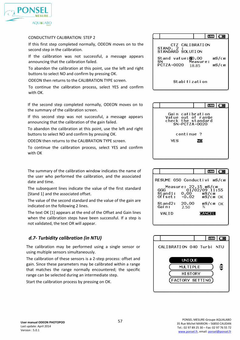
57
PONSEL MESURE-Groupe AQUALABO 35 Rue Michel MARION – 56850 CAUDAN Tel.: 02 97 89 25 30 – Fax: 02 97 76 55 72 www.ponsel.fr, email: [email protected]
User manual ODEON PHOTOPOD Last update: April 2014 Version : 5.0.1
d.7- Turbidity calibration (in NTU)
The calibration may be performed using a single sensor or using multiple sensors simultaneously.
The calibration of these sensors is a 2-step process: offset and gain. Since these parameters may be calibrated within a range that matches the range normally encountered; the specific range can be selected during an intermediate step.
Start the calibration process by pressing on OK.
CONDUCTIVITY CALIBRATION: STEP 2
If this first step completed normally, ODEON moves on to the second step in the calibration.
If the calibration was not successful, a message appears announcing that the calibration failed.
To abandon the calibration at this point, use the left and right buttons to select NO and confirm by pressing OK.
ODEON then returns to the CALIBRATION TYPE screen.
To continue the calibration process, select YES and confirm with OK.
If the second step completed normally, ODEON moves on to the summary of the calibration screen.
If this second step was not successful, a message appears announcing that the calibration of the gain failed.
To abandon the calibration at this point, use the left and right buttons to select NO and confirm by pressing OK.
ODEON then returns to the CALIBRATION TYPE screen.
To continue the calibration process, select YES and confirm with OK
The summary of the calibration window indicates the name of the user who performed the calibration, and the associated date and time.
The subsequent lines indicate the value of the first standard [Stand 1] and the associated offset.
The value of the second standard and the value of the gain are indicated on the following 2 lines.
The text OK [1] appears at the end of the Offset and Gain lines when the calibration steps have been successful. If a step is not validated, the text OR will appear.
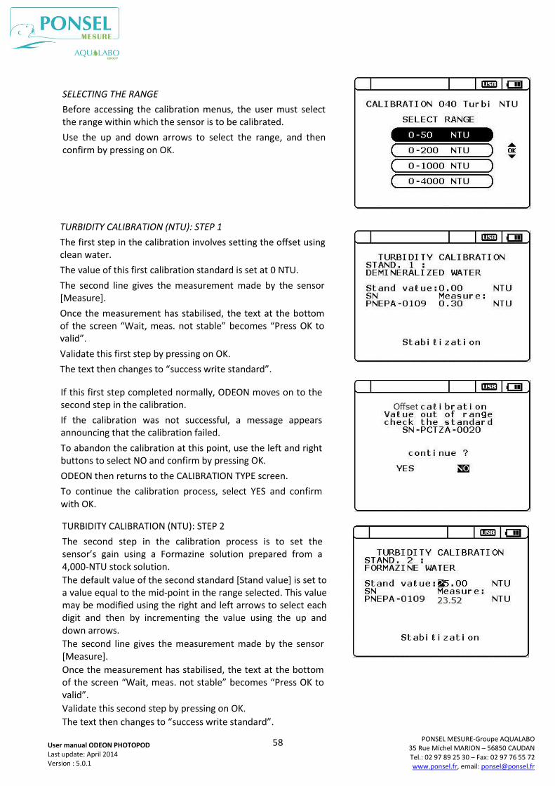
58
PONSEL MESURE-Groupe AQUALABO 35 Rue Michel MARION – 56850 CAUDAN Tel.: 02 97 89 25 30 – Fax: 02 97 76 55 72 www.ponsel.fr, email: [email protected]
User manual ODEON PHOTOPOD Last update: April 2014 Version : 5.0.1
SELECTING THE RANGE
Before accessing the calibration menus, the user must select the range within which the sensor is to be calibrated.
Use the up and down arrows to select the range, and then confirm by pressing on OK.
TURBIDITY CALIBRATION (NTU): STEP 1
The first step in the calibration involves setting the offset using clean water.
The value of this first calibration standard is set at 0 NTU.
The second line gives the measurement made by the sensor [Measure].
Once the measurement has stabilised, the text at the bottom of the screen “Wait, meas. not stable” becomes “Press OK to valid”.
Validate this first step by pressing on OK.
The text then changes to “success write standard”.
If this first step completed normally, ODEON moves on to the second step in the calibration.
If the calibration was not successful, a message appears announcing that the calibration failed.
To abandon the calibration at this point, use the left and right buttons to select NO and confirm by pressing OK.
ODEON then returns to the CALIBRATION TYPE screen.
To continue the calibration process, select YES and confirm with OK.
TURBIDITY CALIBRATION (NTU): STEP 2
The second step in the calibration process is to set the sensor’s gain using a Formazine solution prepared from a 4,000-NTU stock solution.
The default value of the second standard [Stand value] is set to a value equal to the mid-point in the range selected. This value may be modified using the right and left arrows to select each digit and then by incrementing the value using the up and down arrows.
The second line gives the measurement made by the sensor [Measure].
Once the measurement has stabilised, the text at the bottom of the screen “Wait, meas. not stable” becomes “Press OK to valid”.
Validate this second step by pressing on OK.
The text then changes to “success write standard”.
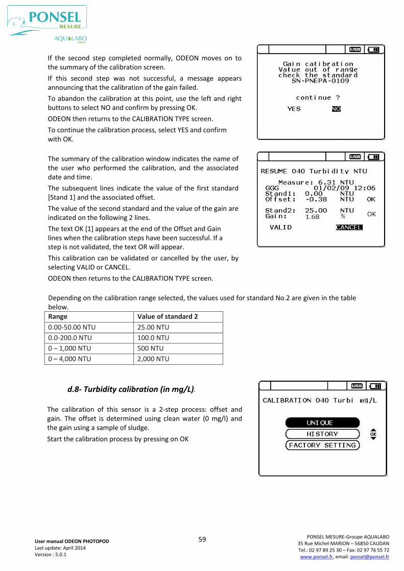
59
PONSEL MESURE-Groupe AQUALABO 35 Rue Michel MARION – 56850 CAUDAN Tel.: 02 97 89 25 30 – Fax: 02 97 76 55 72 www.ponsel.fr, email: [email protected]
User manual ODEON PHOTOPOD Last update: April 2014 Version : 5.0.1
Depending on the calibration range selected, the values used for standard No.2 are given in the table below.
Range Value of standard 2
0.00-50.00 NTU 25.00 NTU
0.0-200.0 NTU 100.0 NTU
0 – 1,000 NTU 500 NTU
0 – 4,000 NTU 2,000 NTU
d.8- Turbidity calibration (in mg/L).
If the second step completed normally, ODEON moves on to the summary of the calibration screen.
If this second step was not successful, a message appears announcing that the calibration of the gain failed.
To abandon the calibration at this point, use the left and right buttons to select NO and confirm by pressing OK.
ODEON then returns to the CALIBRATION TYPE screen.
To continue the calibration process, select YES and confirm with OK.
The summary of the calibration window indicates the name of the user who performed the calibration, and the associated date and time.
The subsequent lines indicate the value of the first standard [Stand 1] and the associated offset.
The value of the second standard and the value of the gain are indicated on the following 2 lines.
The text OK [1] appears at the end of the Offset and Gain lines when the calibration steps have been successful. If a step is not validated, the text OR will appear.
This calibration can be validated or cancelled by the user, by selecting VALID or CANCEL.
ODEON then returns to the CALIBRATION TYPE screen.
The calibration of this sensor is a 2-step process: offset and gain. The offset is determined using clean water (0 mg/l) and the gain using a sample of sludge.
Start the calibration process by pressing on OK
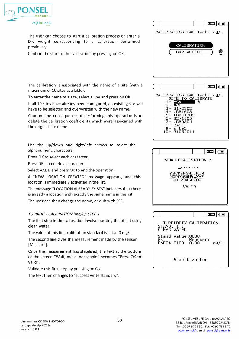
60
PONSEL MESURE-Groupe AQUALABO 35 Rue Michel MARION – 56850 CAUDAN Tel.: 02 97 89 25 30 – Fax: 02 97 76 55 72 www.ponsel.fr, email: [email protected]
User manual ODEON PHOTOPOD Last update: April 2014 Version : 5.0.1
The user can choose to start a calibration process or enter a Dry weight corresponding to a calibration performed previously.
Confirm the start of the calibration by pressing on OK.
The calibration is associated with the name of a site (with a maximum of 10 sites available).
To enter the name of a site, select a line and press on OK.
If all 10 sites have already been configured, an existing site will have to be selected and overwritten with the new name.
Caution: the consequence of performing this operation is to delete the calibration coefficients which were associated with the original site name.
Use the up/down and right/left arrows to select the alphanumeric characters.
Press OK to select each character.
Press DEL to delete a character.
Select VALID and press OK to end the operation.
A "NEW LOCATION CREATED" message appears, and this location is immediately activated in the list.
The message "LOCATION ALREADY EXISTS" indicates that there is already a location with exactly the same name in the list
The user can then change the name, or quit with ESC.
TURBIDITY CALIBRATION (mg/L): STEP 1
The first step in the calibration involves setting the offset using clean water.
The value of this first calibration standard is set at 0 mg/L.
The second line gives the measurement made by the sensor [Measure].
Once the measurement has stabilised, the text at the bottom of the screen “Wait, meas. not stable” becomes “Press OK to valid”.
Validate this first step by pressing on OK.
The text then changes to “success write standard”.
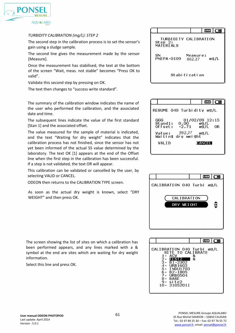
61
PONSEL MESURE-Groupe AQUALABO 35 Rue Michel MARION – 56850 CAUDAN Tel.: 02 97 89 25 30 – Fax: 02 97 76 55 72 www.ponsel.fr, email: [email protected]
User manual ODEON PHOTOPOD Last update: April 2014 Version : 5.0.1
TURBIDITY CALIBRATION (mg/L): STEP 2
The second step in the calibration process is to set the sensor’s gain using a sludge sample.
The second line gives the measurement made by the sensor [Measure].
Once the measurement has stabilised, the text at the bottom of the screen “Wait, meas. not stable” becomes “Press OK to valid”.
Validate this second step by pressing on OK.
The text then changes to “success write standard”.
The summary of the calibration window indicates the name of the user who performed the calibration, and the associated date and time.
The subsequent lines indicate the value of the first standard [Stan 1] and the associated offset.
The value measured for the sample of material is indicated, and the text “Waiting for dry weight” indicates that the calibration process has not finished, since the sensor has not yet been informed of the actual SS value determined by the laboratory. The text OK [1] appears at the end of the Offset line when the first step in the calibration has been successful. If a step is not validated, the text OR will appear.
This calibration can be validated or cancelled by the user, by selecting VALID or CANCEL.
ODEON then returns to the CALIBRATION TYPE screen.
As soon as the actual dry weight is known, select “DRY WEIGHT” and then press OK.
The screen showing the list of sites on which a calibration has been performed appears, and any lines marked with a & symbol at the end are sites which are waiting for dry weight information.
Select this line and press OK.
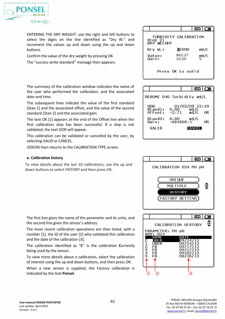
62
PONSEL MESURE-Groupe AQUALABO 35 Rue Michel MARION – 56850 CAUDAN Tel.: 02 97 89 25 30 – Fax: 02 97 76 55 72 www.ponsel.fr, email: [email protected]
User manual ODEON PHOTOPOD Last update: April 2014 Version : 5.0.1
e. Calibration history
ENTERING THE DRY WEIGHT: use the right and left buttons to select the digits on the line identified as “Dry W.” and increment the values up and down using the up and down buttons.
Confirm the value of the dry weight by pressing OK.
The “success write standard” message then appears.
The summary of the calibration window indicates the name of the user who performed the calibration, and the associated date and time.
The subsequent lines indicate the value of the first standard [Stan 1] and the associated offset, and the value of the second standard [Stan 2] and the associated gain.
The text OK [1] appears at the end of the Offset line when the first calibration step has been successful. If a step is not validated, the text OOR will appear.
This calibration can be validated or cancelled by the user, by selecting VALID or CANCEL.
ODEON then returns to the CALIBRATION TYPE screen.
To view details about the last 10 calibrations, use the up and down buttons to select HISTORY and then press OK.
The first line gives the name of the parameter and its units, and the second line gives the sensor’s address.
The most recent calibration operations are then listed, with a number [1], the ID of the user [2] who validated this calibration and the date of the calibration [3].
The calibration identified as “C“ is the calibration Currently being used by the sensor.
To view more details about a calibration, select the calibration of interest using the up and down buttons, and then press OK.
When a new sensor is supplied, the Factory calibration is indicated by the text Ponsel.
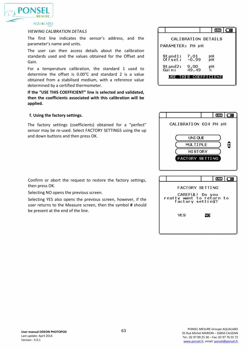
63
PONSEL MESURE-Groupe AQUALABO 35 Rue Michel MARION – 56850 CAUDAN Tel.: 02 97 89 25 30 – Fax: 02 97 76 55 72 www.ponsel.fr, email: [email protected]
User manual ODEON PHOTOPOD Last update: April 2014 Version : 5.0.1
f. Using the factory settings.
VIEWING CALIBRATION DETAILS
The first line indicates the sensor’s address, and the parameter’s name and units.
The user can then access details about the calibration standards used and the values obtained for the Offset and Gain.
For a temperature calibration, the standard 1 used to determine the offset is 0.00°C and standard 2 is a value obtained from a stabilised medium, with a reference value determined by a certified thermometer.
If the “USE THIS COEFFICIENT” line is selected and validated, then the coefficients associated with this calibration will be applied.
The factory settings (coefficients) obtained for a “perfect” sensor may be re-used. Select FACTORY SETTINGS using the up and down buttons and then press OK.
Confirm or abort the request to restore the factory settings, then press OK.
Selecting NO opens the previous screen.
Selecting YES also opens the previous screen, however, if the user returns to the Measure screen, then the symbol # should be present at the end of the line.
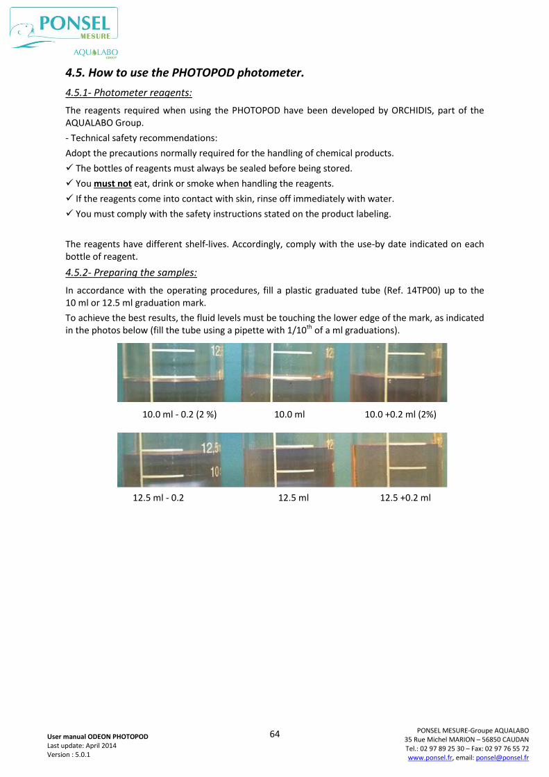
64
PONSEL MESURE-Groupe AQUALABO 35 Rue Michel MARION – 56850 CAUDAN Tel.: 02 97 89 25 30 – Fax: 02 97 76 55 72 www.ponsel.fr, email: [email protected]
User manual ODEON PHOTOPOD Last update: April 2014 Version : 5.0.1
4.5. How to use the PHOTOPOD photometer.
4.5.1- Photometer reagents:
The reagents required when using the PHOTOPOD have been developed by ORCHIDIS, part of the AQUALABO Group.
- Technical safety recommendations:
Adopt the precautions normally required for the handling of chemical products.
The bottles of reagents must always be sealed before being stored.
You must not eat, drink or smoke when handling the reagents.
If the reagents come into contact with skin, rinse off immediately with water.
You must comply with the safety instructions stated on the product labeling.
The reagents have different shelf-lives. Accordingly, comply with the use-by date indicated on each bottle of reagent.
4.5.2- Preparing the samples:
In accordance with the operating procedures, fill a plastic graduated tube (Ref. 14TP00) up to the 10 ml or 12.5 ml graduation mark.
To achieve the best results, the fluid levels must be touching the lower edge of the mark, as indicated in the photos below (fill the tube using a pipette with 1/10th of a ml graduations).
10.0 ml - 0.2 (2 %) 10.0 ml 10.0 +0.2 ml (2%)
10,0 ml + 0,2 (2 %)
12.5 ml - 0.2 12.5 ml 12.5 +0.2 ml
10,0 ml + 0,2 (2 %)
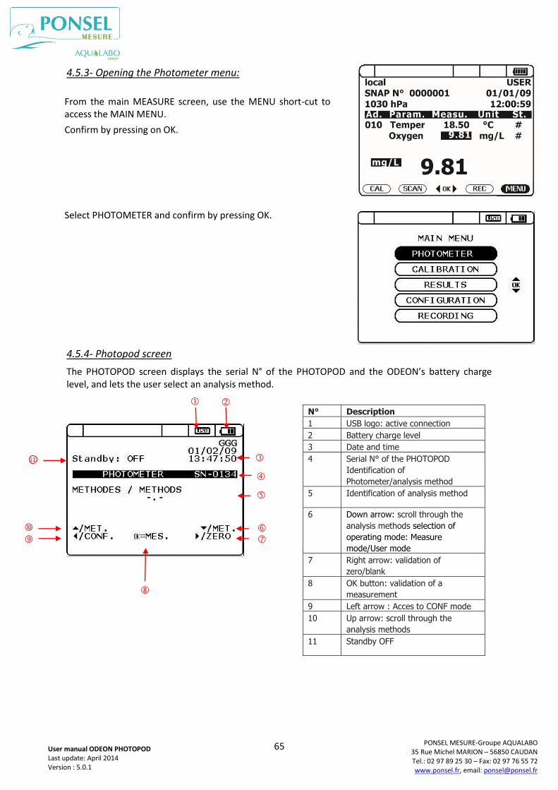
65
PONSEL MESURE-Groupe AQUALABO 35 Rue Michel MARION – 56850 CAUDAN Tel.: 02 97 89 25 30 – Fax: 02 97 76 55 72 www.ponsel.fr, email: [email protected]
User manual ODEON PHOTOPOD Last update: April 2014 Version : 5.0.1
4.5.3- Opening the Photometer menu:
4.5.4- Photopod screen
The PHOTOPOD screen displays the serial N° of the PHOTOPOD and the ODEON’s battery charge level, and lets the user select an analysis method.
From the main MEASURE screen, use the MENU short-cut to access the MAIN MENU.
Confirm by pressing on OK.
Select PHOTOMETER and confirm by pressing OK.
N° Description
1 USB logo: active connection
2 Battery charge level
3 Date and time
4 Serial N° of the PHOTOPOD
Identification of
Photometer/analysis method
5 Identification of analysis method
6 Down arrow: scroll through the
analysis methods selection of
operating mode: Measure
mode/User mode
7 Right arrow: validation of
zero/blank
8 OK button: validation of a
measurement
9 Left arrow : Acces to CONF mode
10 Up arrow: scroll through the
analysis methods
11 Standby OFF
11
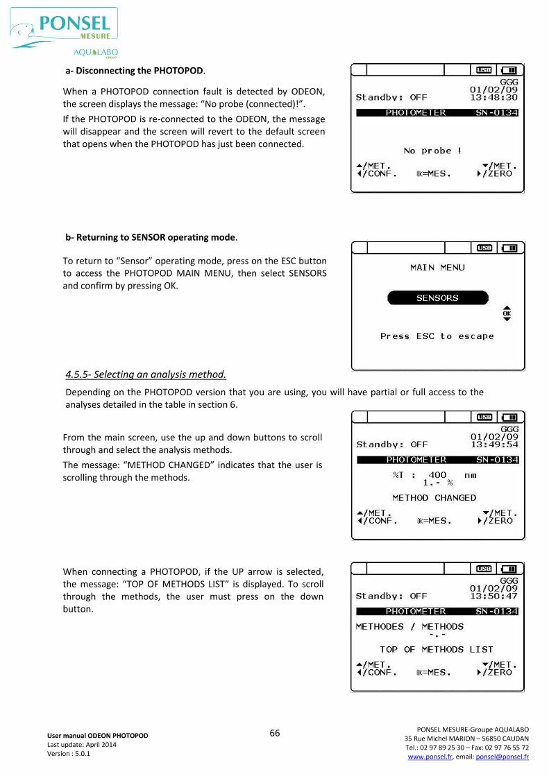
66
PONSEL MESURE-Groupe AQUALABO 35 Rue Michel MARION – 56850 CAUDAN Tel.: 02 97 89 25 30 – Fax: 02 97 76 55 72 www.ponsel.fr, email: [email protected]
User manual ODEON PHOTOPOD Last update: April 2014 Version : 5.0.1
a- Disconnecting the PHOTOPOD.
b- Returning to SENSOR operating mode.
4.5.5- Selecting an analysis method.
Depending on the PHOTOPOD version that you are using, you will have partial or full access to the analyses detailed in the table in section 6.
When a PHOTOPOD connection fault is detected by ODEON, the screen displays the message: “No probe (connected)!”.
If the PHOTOPOD is re-connected to the ODEON, the message will disappear and the screen will revert to the default screen that opens when the PHOTOPOD has just been connected.
To return to “Sensor” operating mode, press on the ESC button to access the PHOTOPOD MAIN MENU, then select SENSORS and confirm by pressing OK.
From the main screen, use the up and down buttons to scroll through and select the analysis methods.
The message: “METHOD CHANGED” indicates that the user is scrolling through the methods.
When connecting a PHOTOPOD, if the UP arrow is selected, the message: “TOP OF METHODS LIST” is displayed. To scroll through the methods, the user must press on the down button.
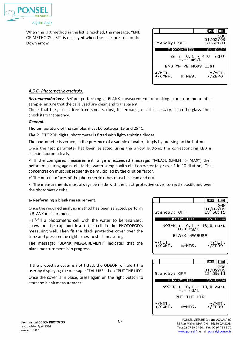
67
PONSEL MESURE-Groupe AQUALABO 35 Rue Michel MARION – 56850 CAUDAN Tel.: 02 97 89 25 30 – Fax: 02 97 76 55 72 www.ponsel.fr, email: [email protected]
User manual ODEON PHOTOPOD Last update: April 2014 Version : 5.0.1
4.5.6- Photometric analysis.
Recommendations: Before performing a BLANK measurement or making a measurement of a sample, ensure that the cells used are clean and transparent. Check that the glass is free from smears, dust, fingermarks, etc. If necessary, clean the glass, then check its transparency.
General:
The temperature of the samples must be between 15 and 25 °C.
The PHOTOPOD digital photometer is fitted with light-emitting diodes.
The photometer is zeroed, in the presence of a sample of water, simply by pressing on the button.
Once the test parameter has been selected using the arrow buttons, the corresponding LED is selected automatically.
If the configured measurement range is exceeded (message: “MEASUREMENT > MAX”) then before measuring again, dilute the water sample with dilution water (e.g.: as a 1 in 10 dilution). The concentration must subsequently be multiplied by the dilution factor.
The outer surfaces of the photometric tubes must be clean and dry.
The measurements must always be made with the black protective cover correctly positioned over the photometric tube.
a- Performing a blank measurement.
When the last method in the list is reached, the message: “END OF METHODS LIST” is displayed when the user presses on the Down arrow.
Once the required analysis method has been selected, perform a BLANK measurement.
Half-fill a photometric cell with the water to be analysed, screw on the cap and insert the cell in the PHOTOPOD’s measuring well. Then fit the black protective cover over the tube and press on the right arrow to start measuring.
The message: “BLANK MEASUREMENT” indicates that the blank measurement is in progress.
If the protective cover is not fitted, the ODEON will alert the user by displaying the message: “FAILURE” then “PUT THE LID”.
Once the cover is in place, press again on the right button to start the blank measurement.
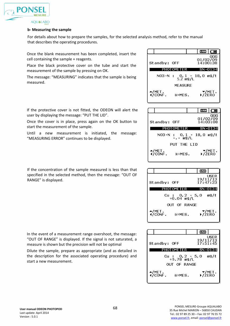
68
PONSEL MESURE-Groupe AQUALABO 35 Rue Michel MARION – 56850 CAUDAN Tel.: 02 97 89 25 30 – Fax: 02 97 76 55 72 www.ponsel.fr, email: [email protected]
User manual ODEON PHOTOPOD Last update: April 2014 Version : 5.0.1
b- Measuring the sample
For details about how to prepare the samples, for the selected analysis method, refer to the manual that describes the operating procedures.
Once the blank measurement has been completed, insert the cell containing the sample + reagents.
Place the black protective cover on the tube and start the measurement of the sample by pressing on OK.
The message: “MEASURING” indicates that the sample is being measured.
If the protective cover is not fitted, the ODEON will alert the user by displaying the message: “PUT THE LID”.
Once the cover is in place, press again on the OK button to start the measurement of the sample.
Until a new measurement is initiated, the message: “MEASURING ERROR” continues to be displayed.
In the event of a measurement range overshoot, the message: “OUT OF RANGE” is displayed. If the signal is not saturated, a measure is shown but the precision will not be optimal
Dilute the sample, prepare as appropriate (and as detailed in the description for the associated operating procedure) and start a new measurement.
If the concentration of the sample measured is less than that specified in the selected method, then the message: “OUT OF RANGE” is displayed.
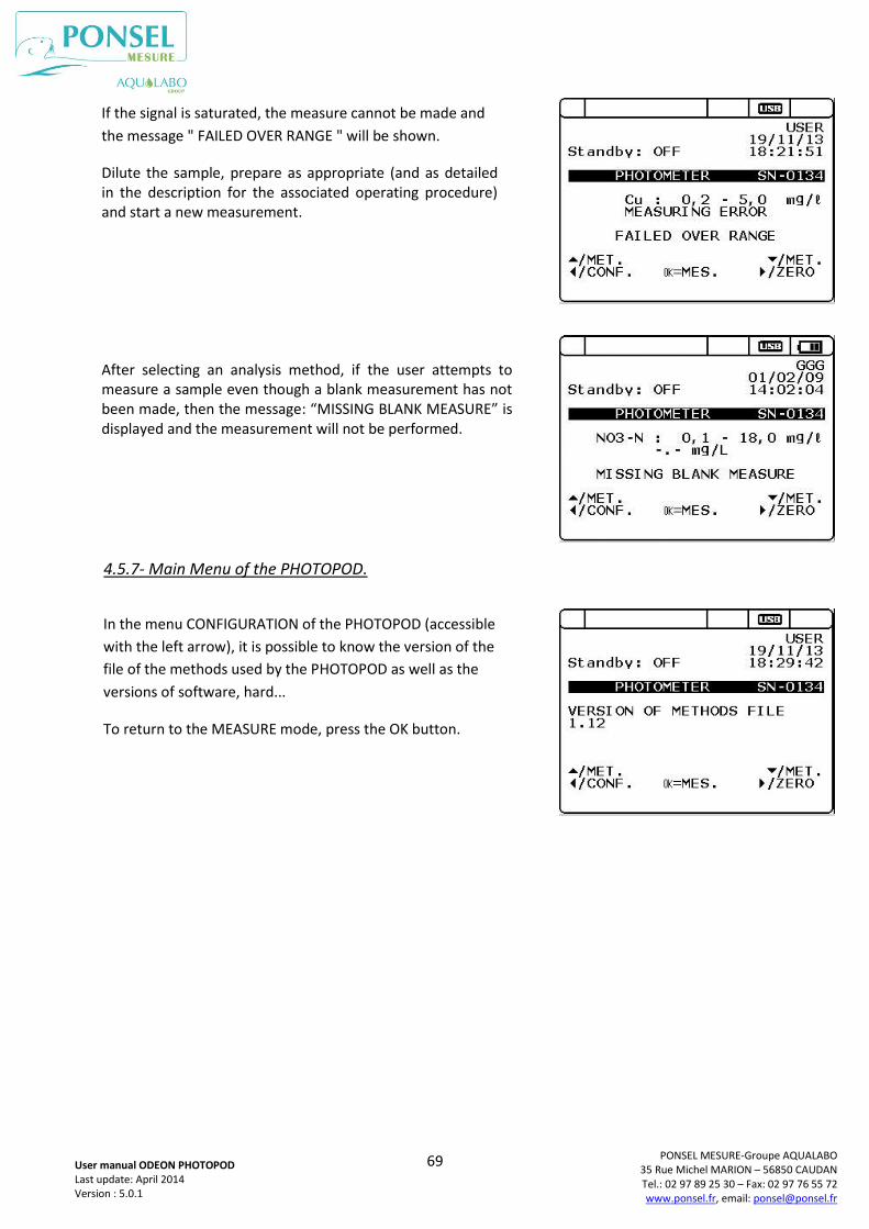
69
PONSEL MESURE-Groupe AQUALABO 35 Rue Michel MARION – 56850 CAUDAN Tel.: 02 97 89 25 30 – Fax: 02 97 76 55 72 www.ponsel.fr, email: [email protected]
User manual ODEON PHOTOPOD Last update: April 2014 Version : 5.0.1
4.5.7- Main Menu of the PHOTOPOD.
After selecting an analysis method, if the user attempts to measure a sample even though a blank measurement has not been made, then the message: “MISSING BLANK MEASURE” is displayed and the measurement will not be performed.
If the signal is saturated, the measure cannot be made and
the message " FAILED OVER RANGE " will be shown.
Dilute the sample, prepare as appropriate (and as detailed in the description for the associated operating procedure) and start a new measurement.
In the menu CONFIGURATION of the PHOTOPOD (accessible
with the left arrow), it is possible to know the version of the
file of the methods used by the PHOTOPOD as well as the
versions of software, hard...
To return to the MEASURE mode, press the OK button.
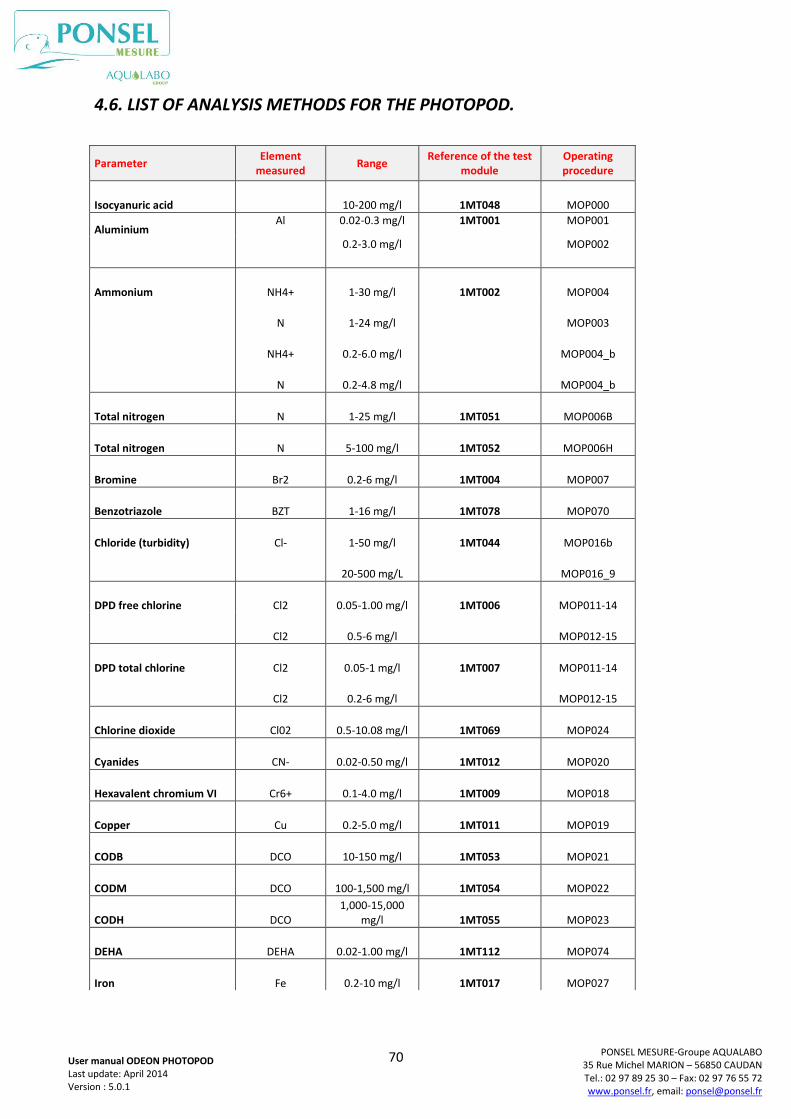
70
PONSEL MESURE-Groupe AQUALABO 35 Rue Michel MARION – 56850 CAUDAN Tel.: 02 97 89 25 30 – Fax: 02 97 76 55 72 www.ponsel.fr, email: [email protected]
User manual ODEON PHOTOPOD Last update: April 2014 Version : 5.0.1
4.6. LIST OF ANALYSIS METHODS FOR THE PHOTOPOD.
Parameter Element
measured Range
Reference of the test module
Operating procedure
Isocyanuric acid 10-200 mg/l 1MT048 MOP000
Aluminium Al 0.02-0.3 mg/l 1MT001 MOP001
0.2-3.0 mg/l MOP002
Ammonium NH4+ 1-30 mg/l 1MT002 MOP004
N 1-24 mg/l MOP003
NH4+ 0.2-6.0 mg/l MOP004_b
N 0.2-4.8 mg/l MOP004_b
Total nitrogen N 1-25 mg/l 1MT051 MOP006B
Total nitrogen N 5-100 mg/l 1MT052 MOP006H
Bromine Br2 0.2-6 mg/l 1MT004 MOP007
Benzotriazole BZT 1-16 mg/l 1MT078 MOP070
Chloride (turbidity) Cl- 1-50 mg/l 1MT044 MOP016b
20-500 mg/L MOP016_9
DPD free chlorine Cl2 0.05-1.00 mg/l 1MT006 MOP011-14
Cl2 0.5-6 mg/l MOP012-15
DPD total chlorine Cl2 0.05-1 mg/l 1MT007 MOP011-14
Cl2 0.2-6 mg/l MOP012-15
Chlorine dioxide Cl02 0.5-10.08 mg/l 1MT069 MOP024
Cyanides CN- 0.02-0.50 mg/l 1MT012 MOP020
Hexavalent chromium VI Cr6+ 0.1-4.0 mg/l 1MT009 MOP018
Copper Cu 0.2-5.0 mg/l 1MT011 MOP019
CODB DCO 10-150 mg/l 1MT053 MOP021
CODM DCO 100-1,500 mg/l 1MT054 MOP022
CODH DCO 1,000-15,000
mg/l 1MT055 MOP023
DEHA DEHA 0.02-1.00 mg/l 1MT112 MOP074
Iron Fe 0.2-10 mg/l 1MT017 MOP027
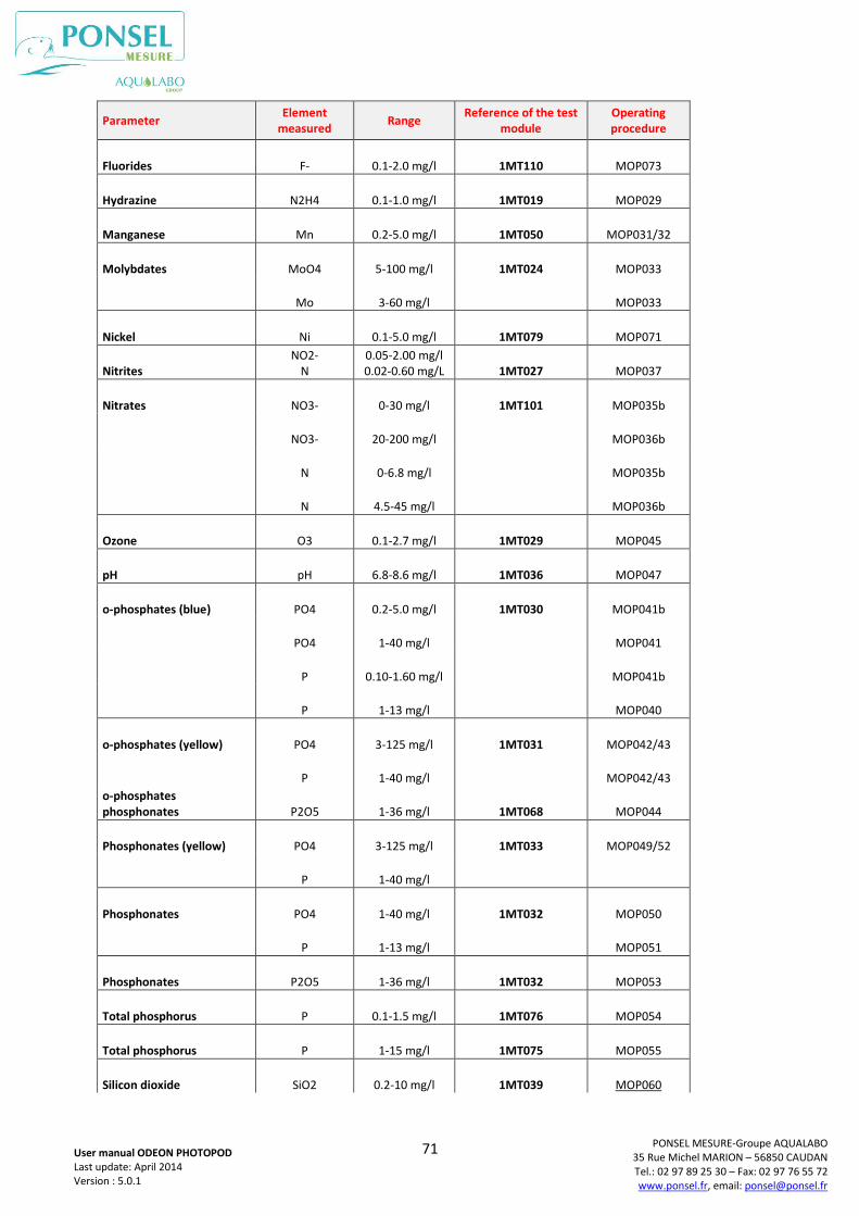
71
PONSEL MESURE-Groupe AQUALABO 35 Rue Michel MARION – 56850 CAUDAN Tel.: 02 97 89 25 30 – Fax: 02 97 76 55 72 www.ponsel.fr, email: [email protected]
User manual ODEON PHOTOPOD Last update: April 2014 Version : 5.0.1
Parameter Element
measured Range
Reference of the test module
Operating procedure
Fluorides F- 0.1-2.0 mg/l 1MT110 MOP073
Hydrazine N2H4 0.1-1.0 mg/l 1MT019 MOP029
Manganese Mn 0.2-5.0 mg/l 1MT050 MOP031/32
Molybdates MoO4 5-100 mg/l 1MT024 MOP033
Mo 3-60 mg/l MOP033
Nickel Ni 0.1-5.0 mg/l 1MT079 MOP071
Nitrites NO2-
N 0.05-2.00 mg/l 0.02-0.60 mg/L 1MT027 MOP037
Nitrates NO3- 0-30 mg/l 1MT101 MOP035b
NO3- 20-200 mg/l MOP036b
N 0-6.8 mg/l MOP035b
N 4.5-45 mg/l MOP036b
Ozone O3 0.1-2.7 mg/l 1MT029 MOP045
pH pH 6.8-8.6 mg/l 1MT036 MOP047
o-phosphates (blue) PO4 0.2-5.0 mg/l 1MT030 MOP041b
PO4 1-40 mg/l MOP041
P 0.10-1.60 mg/l MOP041b
P 1-13 mg/l MOP040
o-phosphates (yellow) PO4 3-125 mg/l 1MT031 MOP042/43
P 1-40 mg/l MOP042/43
o-phosphates phosphonates P2O5 1-36 mg/l 1MT068 MOP044
Phosphonates (yellow) PO4 3-125 mg/l 1MT033 MOP049/52
P 1-40 mg/l
Phosphonates PO4 1-40 mg/l 1MT032 MOP050
P 1-13 mg/l MOP051
Phosphonates P2O5 1-36 mg/l 1MT032 MOP053
Total phosphorus P 0.1-1.5 mg/l 1MT076 MOP054
Total phosphorus P 1-15 mg/l 1MT075 MOP055
Silicon dioxide SiO2 0.2-10 mg/l 1MT039 MOP060
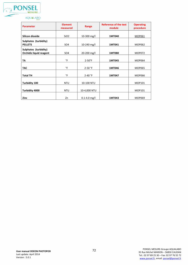
72
PONSEL MESURE-Groupe AQUALABO 35 Rue Michel MARION – 56850 CAUDAN Tel.: 02 97 89 25 30 – Fax: 02 97 76 55 72 www.ponsel.fr, email: [email protected]
User manual ODEON PHOTOPOD Last update: April 2014 Version : 5.0.1
Parameter Element
measured Range
Reference of the test module
Operating procedure
Silicon dioxide SiO2 10-300 mg/l 1MT040 MOP061
Sulphates (turbidity) PELLETS SO4 10-240 mg/l 1MT041 MOP062
Sulphates (turbidity) Orchidis liquid reagent SO4 20-200 mg/l 1MT080 MOP072
TA °F 2-50°F 1MT045 MOP064
TAC °F 2-50 °F 1MT046 MOP065
Total TH °F 2-40 °F 1MT047 MOP066
Turbidity 100 NTU 10-100 NTU MOP101
Turbidity 4000 NTU 10-4,000 NTU MOP101
Zinc Zn 0.1-4.0 mg/l 1MT043 MOP069
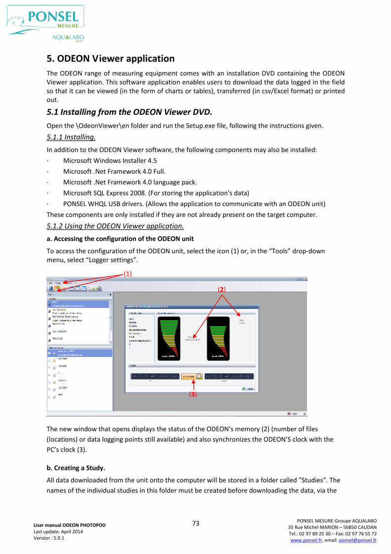
73
PONSEL MESURE-Groupe AQUALABO 35 Rue Michel MARION – 56850 CAUDAN Tel.: 02 97 89 25 30 – Fax: 02 97 76 55 72 www.ponsel.fr, email: [email protected]
User manual ODEON PHOTOPOD Last update: April 2014 Version : 5.0.1
5. ODEON Viewer application
The ODEON range of measuring equipment comes with an installation DVD containing the ODEON Viewer application. This software application enables users to download the data logged in the field so that it can be viewed (in the form of charts or tables), transferred (in csv/Excel format) or printed out.
5.1 Installing from the ODEON Viewer DVD.
Open the \OdeonViewer\en folder and run the Setup.exe file, following the instructions given.
5.1.1 Installing.
In addition to the ODEON Viewer software, the following components may also be installed:
· Microsoft Windows Installer 4.5
· Microsoft .Net Framework 4.0 Full.
· Microsoft .Net Framework 4.0 language pack.
· Microsoft SQL Express 2008. (For storing the application's data)
· PONSEL WHQL USB drivers. (Allows the application to communicate with an ODEON unit)
These components are only installed if they are not already present on the target computer.
5.1.2 Using the ODEON Viewer application.
a. Accessing the configuration of the ODEON unit
To access the configuration of the ODEON unit, select the icon (1) or, in the “Tools” drop-down menu, select “Logger settings”.
The new window that opens displays the status of the ODEON’s memory (2) (number of files
(locations) or data logging points still available) and also synchronizes the ODEON’S clock with the
PC’s clock (3).
b. Creating a Study.
All data downloaded from the unit onto the computer will be stored in a folder called "Studies". The
names of the individual studies in this folder must be created before downloading the data, via the
(1)
(2)
(3)
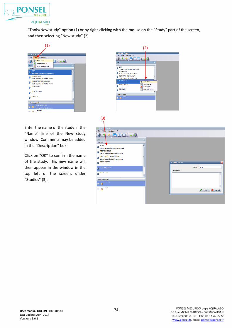
74
PONSEL MESURE-Groupe AQUALABO 35 Rue Michel MARION – 56850 CAUDAN Tel.: 02 97 89 25 30 – Fax: 02 97 76 55 72 www.ponsel.fr, email: [email protected]
User manual ODEON PHOTOPOD Last update: April 2014 Version : 5.0.1
“Tools/New study” option (1) or by right-clicking with the mouse on the “Study” part of the screen,
and then selecting “New study” (2).
(1)
Enter the name of the study in the
“Name” line of the New study
window. Comments may be added
in the “Description” box.
Click on “OK” to confirm the name
of the study. This new name will
then appear in the window in the
top left of the screen, under
”Studies” (3).
(2)
(3)
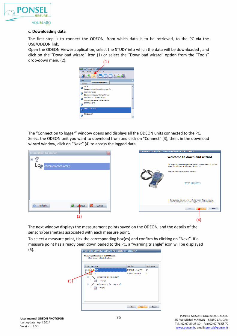
75
PONSEL MESURE-Groupe AQUALABO 35 Rue Michel MARION – 56850 CAUDAN Tel.: 02 97 89 25 30 – Fax: 02 97 76 55 72 www.ponsel.fr, email: [email protected]
User manual ODEON PHOTOPOD Last update: April 2014 Version : 5.0.1
c. Downloading data
The first step is to connect the ODEON, from which data is to be retrieved, to the PC via the USB/ODEON link. Open the ODEON Viewer application, select the STUDY into which the data will be downloaded , and click on the “Download wizard” icon (1) or select the “Download wizard” option from the “Tools” drop-down menu (2).
The “Connection to logger” window opens and displays all the ODEON units connected to the PC. Select the ODEON unit you want to download from and click on “Connect” (3), then, in the download wizard window, click on “Next” (4) to access the logged data.
The next window displays the measurement points saved on the ODEON, and the details of the sensors/parameters associated with each measure point.
To select a measure point, tick the corresponding box(es) and confirm by clicking on “Next”. If a measure point has already been downloaded to the PC, a “warning triangle” icon will be displayed (5).
(3) (4)
(5)
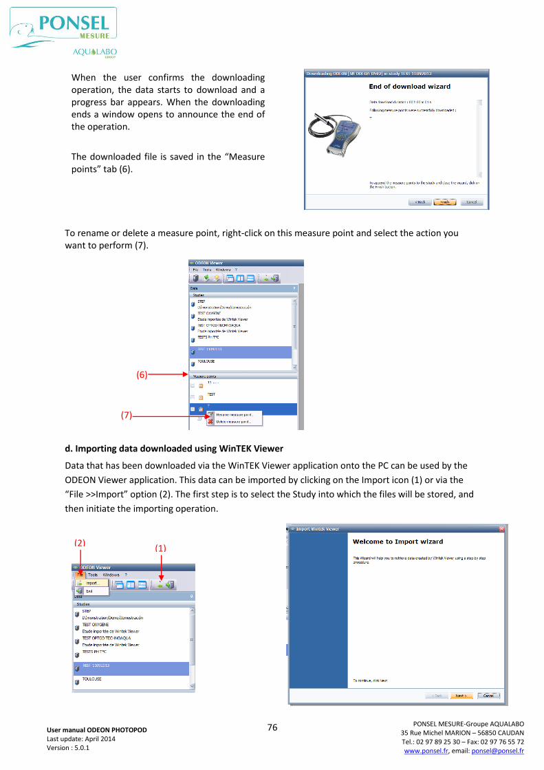
76
PONSEL MESURE-Groupe AQUALABO 35 Rue Michel MARION – 56850 CAUDAN Tel.: 02 97 89 25 30 – Fax: 02 97 76 55 72 www.ponsel.fr, email: [email protected]
User manual ODEON PHOTOPOD Last update: April 2014 Version : 5.0.1
To rename or delete a measure point, right-click on this measure point and select the action you want to perform (7).
d. Importing data downloaded using WinTEK Viewer
Data that has been downloaded via the WinTEK Viewer application onto the PC can be used by the
ODEON Viewer application. This data can be imported by clicking on the Import icon (1) or via the
“File >>Import” option (2). The first step is to select the Study into which the files will be stored, and
then initiate the importing operation.
When the user confirms the downloading operation, the data starts to download and a progress bar appears. When the downloading ends a window opens to announce the end of the operation.
The downloaded file is saved in the “Measure points” tab (6).
(6)
(7)
(1) (2)
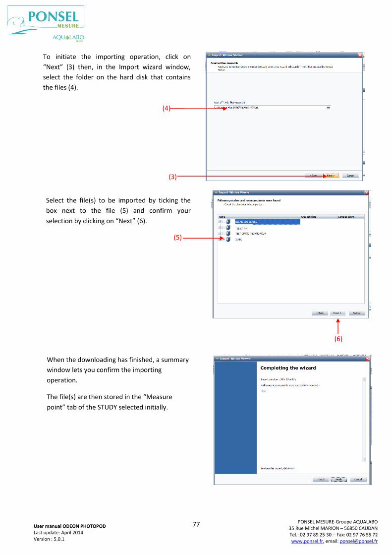
77
PONSEL MESURE-Groupe AQUALABO 35 Rue Michel MARION – 56850 CAUDAN Tel.: 02 97 89 25 30 – Fax: 02 97 76 55 72 www.ponsel.fr, email: [email protected]
User manual ODEON PHOTOPOD Last update: April 2014 Version : 5.0.1
To initiate the importing operation, click on
“Next” (3) then, in the Import wizard window,
select the folder on the hard disk that contains
the files (4).
Select the file(s) to be imported by ticking the
box next to the file (5) and confirm your
selection by clicking on “Next” (6).
When the downloading has finished, a summary
window lets you confirm the importing
operation.
The file(s) are then stored in the “Measure
point” tab of the STUDY selected initially.
(4)
(3)
(5)
(6)
TEST PH
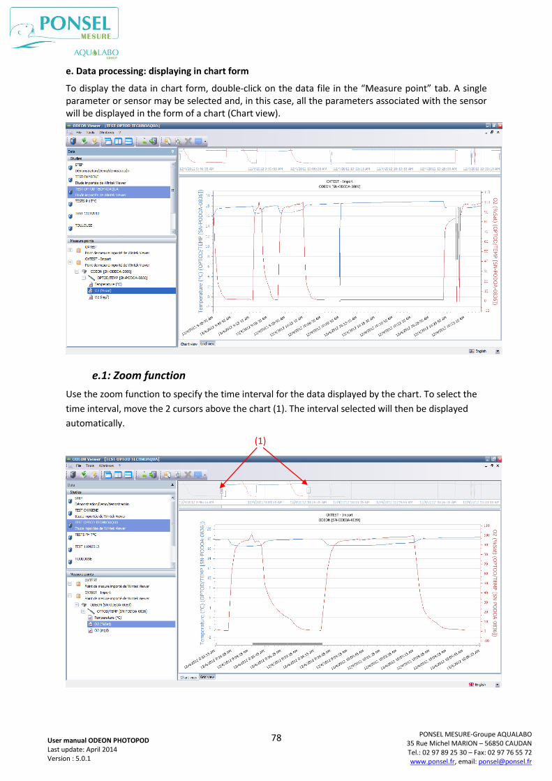
78
PONSEL MESURE-Groupe AQUALABO 35 Rue Michel MARION – 56850 CAUDAN Tel.: 02 97 89 25 30 – Fax: 02 97 76 55 72 www.ponsel.fr, email: [email protected]
User manual ODEON PHOTOPOD Last update: April 2014 Version : 5.0.1
e. Data processing: displaying in chart form
To display the data in chart form, double-click on the data file in the “Measure point” tab. A single parameter or sensor may be selected and, in this case, all the parameters associated with the sensor will be displayed in the form of a chart (Chart view).
e.1: Zoom function
Use the zoom function to specify the time interval for the data displayed by the chart. To select the
time interval, move the 2 cursors above the chart (1). The interval selected will then be displayed
automatically.
(1)
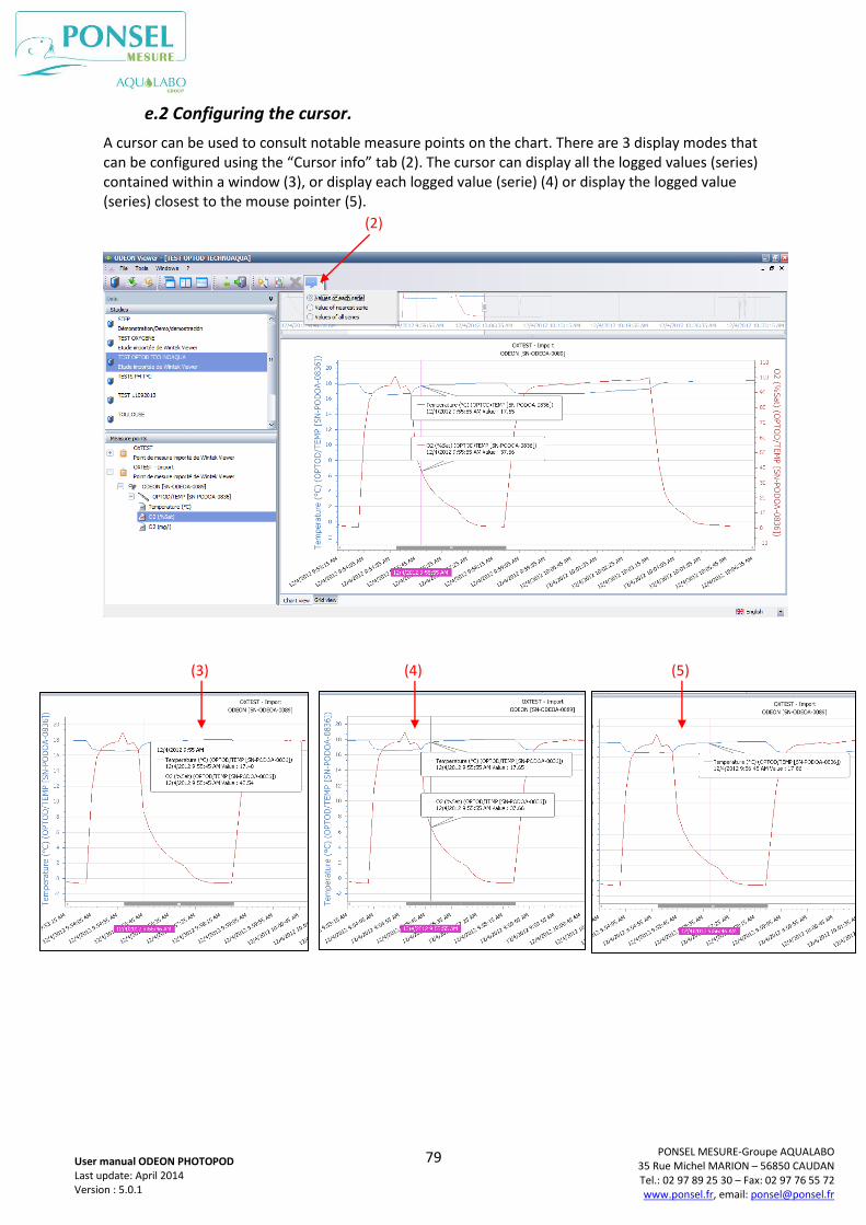
79
PONSEL MESURE-Groupe AQUALABO 35 Rue Michel MARION – 56850 CAUDAN Tel.: 02 97 89 25 30 – Fax: 02 97 76 55 72 www.ponsel.fr, email: [email protected]
User manual ODEON PHOTOPOD Last update: April 2014 Version : 5.0.1
e.2 Configuring the cursor.
A cursor can be used to consult notable measure points on the chart. There are 3 display modes that can be configured using the “Cursor info” tab (2). The cursor can display all the logged values (series) contained within a window (3), or display each logged value (serie) (4) or display the logged value (series) closest to the mouse pointer (5).
(2)
(3) (4) (5)
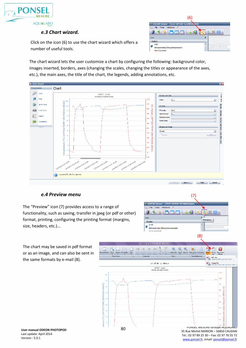
80
PONSEL MESURE-Groupe AQUALABO 35 Rue Michel MARION – 56850 CAUDAN Tel.: 02 97 89 25 30 – Fax: 02 97 76 55 72 www.ponsel.fr, email: [email protected]
User manual ODEON PHOTOPOD Last update: April 2014 Version : 5.0.1
e.3 Chart wizard.
The chart wizard lets the user customize a chart by configuring the following: background color,
images inserted, borders, axes (changing the scales, changing the titles or appearance of the axes,
etc.), the main axes, the title of the chart, the legends, adding annotations, etc.
e.4 Preview menu
Click on the icon (6) to use the chart wizard which offers a
number of useful tools.
(6)
The “Preview” icon (7) provides access to a range of
functionality, such as saving, transfer in jpeg (or pdf or other)
format, printing, configuring the printing format (margins,
size, headers, etc.)...
(7)
The chart may be saved in pdf format
or as an image, and can also be sent in
the same formats by e-mail (8).
(8)

81
PONSEL MESURE-Groupe AQUALABO 35 Rue Michel MARION – 56850 CAUDAN Tel.: 02 97 89 25 30 – Fax: 02 97 76 55 72 www.ponsel.fr, email: [email protected]
User manual ODEON PHOTOPOD Last update: April 2014 Version : 5.0.1
f. Data processing: displaying in grid form
The data can be displayed as a chart or in a grid (or table); to display as a grid, select the “Grid view”
tab (1).
In the “Preview” window that can be accessed by clicking on the icon (2), the grid data can be saved
in “pdf”,“xls”, “xlsx” or “csv” format or sent by e-mail in the same formats (3).
The information provided above the grid includes
the name of the data file, the ODEON’s serial No.,
the name of the sensor and its serial No. The grid
also indicates the data point number, the date
and time when the data was logged, and the
associated parameters.
The bar below the grid displays the total number
of measure points contained in the grid.
(1)
(2)
(3)
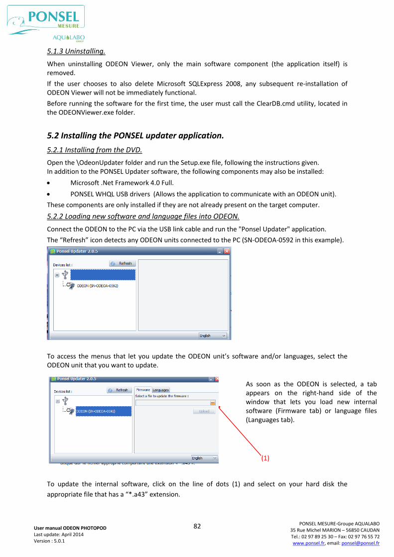
82
PONSEL MESURE-Groupe AQUALABO 35 Rue Michel MARION – 56850 CAUDAN Tel.: 02 97 89 25 30 – Fax: 02 97 76 55 72 www.ponsel.fr, email: [email protected]
User manual ODEON PHOTOPOD Last update: April 2014 Version : 5.0.1
5.1.3 Uninstalling.
When uninstalling ODEON Viewer, only the main software component (the application itself) is removed.
If the user chooses to also delete Microsoft SQLExpress 2008, any subsequent re-installation of ODEON Viewer will not be immediately functional.
Before running the software for the first time, the user must call the ClearDB.cmd utility, located in the ODEONViewer.exe folder.
5.2 Installing the PONSEL updater application.
5.2.1 Installing from the DVD.
Open the \OdeonUpdater folder and run the Setup.exe file, following the instructions given. In addition to the PONSEL Updater software, the following components may also be installed:
Microsoft .Net Framework 4.0 Full.
PONSEL WHQL USB drivers (Allows the application to communicate with an ODEON unit).
These components are only installed if they are not already present on the target computer.
5.2.2 Loading new software and language files into ODEON.
Connect the ODEON to the PC via the USB link cable and run the "Ponsel Updater" application.
The “Refresh” icon detects any ODEON units connected to the PC (SN-ODEOA-0592 in this example).
To access the menus that let you update the ODEON unit’s software and/or languages, select the ODEON unit that you want to update.
To update the internal software, click on the line of dots (1) and select on your hard disk the
appropriate file that has a “*.a43” extension.
As soon as the ODEON is selected, a tab appears on the right-hand side of the window that lets you load new internal software (Firmware tab) or language files (Languages tab).
(1)
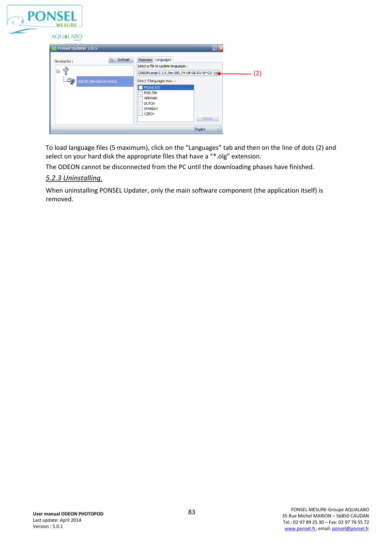
83
PONSEL MESURE-Groupe AQUALABO 35 Rue Michel MARION – 56850 CAUDAN Tel.: 02 97 89 25 30 – Fax: 02 97 76 55 72 www.ponsel.fr, email: [email protected]
User manual ODEON PHOTOPOD Last update: April 2014 Version : 5.0.1
To load language files (5 maximum), click on the “Languages” tab and then on the line of dots (2) and select on your hard disk the appropriate files that have a “*.olg” extension.
The ODEON cannot be disconnected from the PC until the downloading phases have finished.
5.2.3 Uninstalling.
When uninstalling PONSEL Updater, only the main software component (the application itself) is removed.
(2)
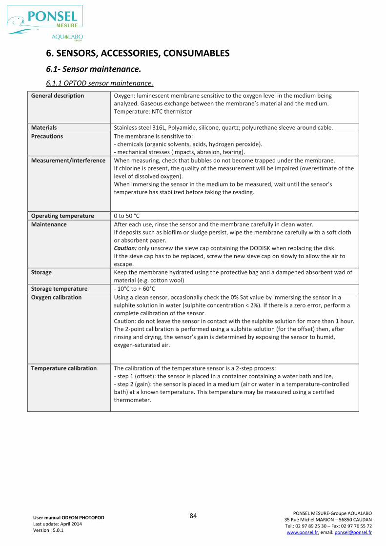
84
PONSEL MESURE-Groupe AQUALABO 35 Rue Michel MARION – 56850 CAUDAN Tel.: 02 97 89 25 30 – Fax: 02 97 76 55 72 www.ponsel.fr, email: [email protected]
User manual ODEON PHOTOPOD Last update: April 2014 Version : 5.0.1
6. SENSORS, ACCESSORIES, CONSUMABLES
6.1- Sensor maintenance.
6.1.1 OPTOD sensor maintenance.
General description Oxygen: luminescent membrane sensitive to the oxygen level in the medium being analyzed. Gaseous exchange between the membrane’s material and the medium. Temperature: NTC thermistor
Materials Stainless steel 316L, Polyamide, silicone, quartz; polyurethane sleeve around cable.
Precautions The membrane is sensitive to: - chemicals (organic solvents, acids, hydrogen peroxide). - mechanical stresses (impacts, abrasion, tearing).
Measurement/Interference When measuring, check that bubbles do not become trapped under the membrane. If chlorine is present, the quality of the measurement will be impaired (overestimate of the level of dissolved oxygen). When immersing the sensor in the medium to be measured, wait until the sensor's temperature has stabilized before taking the reading.
Operating temperature 0 to 50 °C
Maintenance After each use, rinse the sensor and the membrane carefully in clean water. If deposits such as biofilm or sludge persist, wipe the membrane carefully with a soft cloth or absorbent paper. Caution: only unscrew the sieve cap containing the DODISK when replacing the disk. If the sieve cap has to be replaced, screw the new sieve cap on slowly to allow the air to escape.
Storage Keep the membrane hydrated using the protective bag and a dampened absorbent wad of material (e.g. cotton wool)
Storage temperature - 10°C to + 60°C
Oxygen calibration Using a clean sensor, occasionally check the 0% Sat value by immersing the sensor in a sulphite solution in water (sulphite concentration < 2%). If there is a zero error, perform a complete calibration of the sensor. Caution: do not leave the sensor in contact with the sulphite solution for more than 1 hour. The 2-point calibration is performed using a sulphite solution (for the offset) then, after rinsing and drying, the sensor’s gain is determined by exposing the sensor to humid, oxygen-saturated air.
Temperature calibration The calibration of the temperature sensor is a 2-step process: - step 1 (offset): the sensor is placed in a container containing a water bath and ice, - step 2 (gain): the sensor is placed in a medium (air or water in a temperature-controlled bath) at a known temperature. This temperature may be measured using a certified thermometer.
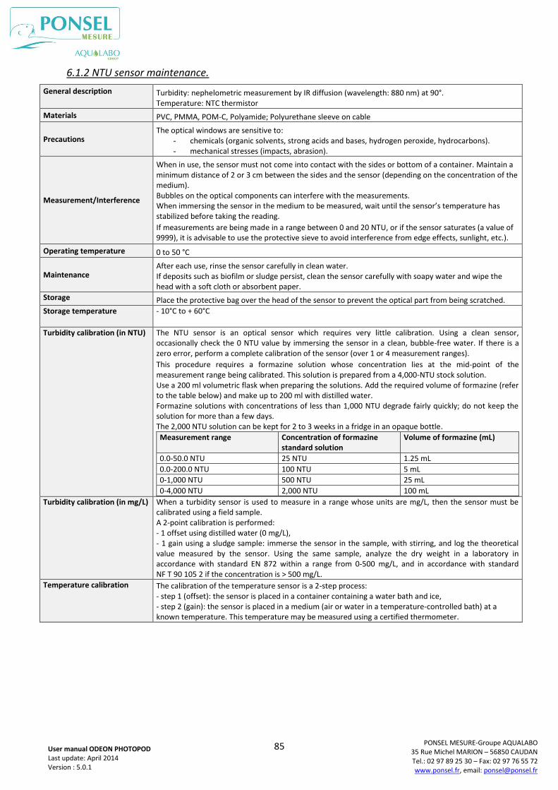
85
PONSEL MESURE-Groupe AQUALABO 35 Rue Michel MARION – 56850 CAUDAN Tel.: 02 97 89 25 30 – Fax: 02 97 76 55 72 www.ponsel.fr, email: [email protected]
User manual ODEON PHOTOPOD Last update: April 2014 Version : 5.0.1
6.1.2 NTU sensor maintenance.
General description Turbidity: nephelometric measurement by IR diffusion (wavelength: 880 nm) at 90°. Temperature: NTC thermistor
Materials PVC, PMMA, POM-C, Polyamide; Polyurethane sleeve on cable
Precautions The optical windows are sensitive to:
- chemicals (organic solvents, strong acids and bases, hydrogen peroxide, hydrocarbons). - mechanical stresses (impacts, abrasion).
Measurement/Interference
When in use, the sensor must not come into contact with the sides or bottom of a container. Maintain a minimum distance of 2 or 3 cm between the sides and the sensor (depending on the concentration of the medium). Bubbles on the optical components can interfere with the measurements. When immersing the sensor in the medium to be measured, wait until the sensor’s temperature has stabilized before taking the reading.
If measurements are being made in a range between 0 and 20 NTU, or if the sensor saturates (a value of 9999), it is advisable to use the protective sieve to avoid interference from edge effects, sunlight, etc.).
Operating temperature 0 to 50 °C
Maintenance After each use, rinse the sensor carefully in clean water. If deposits such as biofilm or sludge persist, clean the sensor carefully with soapy water and wipe the head with a soft cloth or absorbent paper.
Storage Place the protective bag over the head of the sensor to prevent the optical part from being scratched.
Storage temperature - 10°C to + 60°C
Turbidity calibration (in NTU) The NTU sensor is an optical sensor which requires very little calibration. Using a clean sensor, occasionally check the 0 NTU value by immersing the sensor in a clean, bubble-free water. If there is a zero error, perform a complete calibration of the sensor (over 1 or 4 measurement ranges).
This procedure requires a formazine solution whose concentration lies at the mid-point of the measurement range being calibrated. This solution is prepared from a 4,000-NTU stock solution. Use a 200 ml volumetric flask when preparing the solutions. Add the required volume of formazine (refer to the table below) and make up to 200 ml with distilled water. Formazine solutions with concentrations of less than 1,000 NTU degrade fairly quickly; do not keep the solution for more than a few days. The 2,000 NTU solution can be kept for 2 to 3 weeks in a fridge in an opaque bottle.
Measurement range Concentration of formazine standard solution
Volume of formazine (mL)
0.0-50.0 NTU 25 NTU 1.25 mL
0.0-200.0 NTU 100 NTU 5 mL
0-1,000 NTU 500 NTU 25 mL
0-4,000 NTU 2,000 NTU 100 mL
Turbidity calibration (in mg/L) When a turbidity sensor is used to measure in a range whose units are mg/L, then the sensor must be calibrated using a field sample. A 2-point calibration is performed: - 1 offset using distilled water (0 mg/L), - 1 gain using a sludge sample: immerse the sensor in the sample, with stirring, and log the theoretical value measured by the sensor. Using the same sample, analyze the dry weight in a laboratory in accordance with standard EN 872 within a range from 0-500 mg/L, and in accordance with standard NF T 90 105 2 if the concentration is > 500 mg/L.
Temperature calibration The calibration of the temperature sensor is a 2-step process: - step 1 (offset): the sensor is placed in a container containing a water bath and ice, - step 2 (gain): the sensor is placed in a medium (air or water in a temperature-controlled bath) at a known temperature. This temperature may be measured using a certified thermometer.
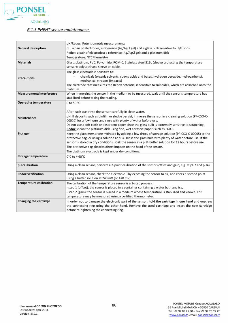
86
PONSEL MESURE-Groupe AQUALABO 35 Rue Michel MARION – 56850 CAUDAN Tel.: 02 97 89 25 30 – Fax: 02 97 76 55 72 www.ponsel.fr, email: [email protected]
User manual ODEON PHOTOPOD Last update: April 2014 Version : 5.0.1
6.1.3 PHEHT sensor maintenance.
General description
pH/Redox: Potentiometric measurement;
pH: a pair of electrodes; a reference (Ag/AgCl gel) and a glass bulb sensitive to H3O+
ions
Redox: a pair of electrodes; a reference (Ag/AgCl gel) and a platinum disk
Temperature: NTC thermistor
Materials Glass, platinum, PVC, Polyamide, POM-C, Stainless steel 316L (sleeve protecting the temperature sensor); polyurethane sleeve on cable.
Precautions
The glass electrode is sensitive to:
- chemicals (organic solvents, strong acids and bases, hydrogen peroxide, hydrocarbons). - mechanical stresses (impacts)
The electrode that measures the Redox potential is sensitive to sulphides, which are adsorbed onto the platinum.
Measurement/Interference When immersing the sensor in the medium to be measured, wait until the sensor’s temperature has stabilized before taking the reading.
Operating temperature 0 to 50 °C
Maintenance
After each use, rinse the sensor carefully in clean water.
pH: If deposits such as biofilm or sludge persist, immerse the sensor in a cleaning solution (PF-CSO-C-00010) for a few hours and rinse with plenty of water before use. Do not use a soft cloth or absorbent paper since the glass bulb is extremely sensitive to scratching. Redox: clean the platinum disk using fine, wet abrasive paper (such as P600).
Storage Keep the glass membrane hydrated by adding a few drops of storage solution (PF-CSO-C-00005) to the protective bag, or using a solution at pH4. Rinse the glass bulb with plenty of water before use. If the sensor is stored in dry conditions, soak the sensor in a pH4 buffer solution for 12 hours before use.
The protective bag absorbs direct impacts on the head of the sensor.
The platinum electrode is kept under dry conditions.
Storage temperature 0°C to + 60°C
pH calibration Using a clean sensor, perform a 2-point calibration of the sensor (offset and gain, e.g. at pH7 and pH4).
Redox verification Using a clean sensor, check the electronic 0 by exposing the sensor to air, and check a second point using a buffer solution at 240 mV (or 470 mV).
Temperature calibration The calibration of the temperature sensor is a 2-step process: - step 1 (offset): the sensor is placed in a container containing a water bath and ice,
- step 2 (gain): the sensor is placed in a medium whose temperature is stabilized and known. This temperature may be measured using a certified thermometer.
Changing the cartridge In order not to damage the electronic part of the sensor, hold the cartridge in one hand and unscrew the connecting ring using the other hand. Remove the used cartridge and insert the new cartridge before re-tightening the connecting ring.
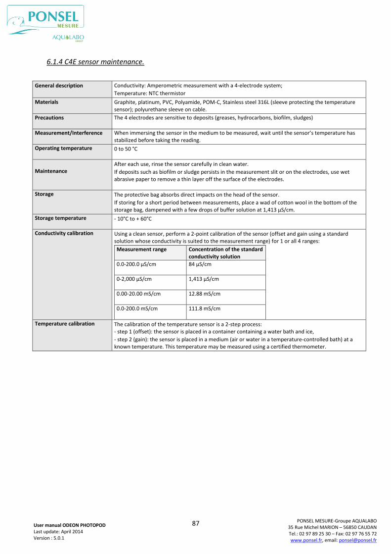
87
PONSEL MESURE-Groupe AQUALABO 35 Rue Michel MARION – 56850 CAUDAN Tel.: 02 97 89 25 30 – Fax: 02 97 76 55 72 www.ponsel.fr, email: [email protected]
User manual ODEON PHOTOPOD Last update: April 2014 Version : 5.0.1
6.1.4 C4E sensor maintenance.
General description Conductivity: Amperometric measurement with a 4-electrode system;
Temperature: NTC thermistor
Materials Graphite, platinum, PVC, Polyamide, POM-C, Stainless steel 316L (sleeve protecting the temperature sensor); polyurethane sleeve on cable.
Precautions The 4 electrodes are sensitive to deposits (greases, hydrocarbons, biofilm, sludges)
Measurement/Interference When immersing the sensor in the medium to be measured, wait until the sensor’s temperature has stabilized before taking the reading.
Operating temperature 0 to 50 °C
Maintenance After each use, rinse the sensor carefully in clean water.
If deposits such as biofilm or sludge persists in the measurement slit or on the electrodes, use wet abrasive paper to remove a thin layer off the surface of the electrodes.
Storage The protective bag absorbs direct impacts on the head of the sensor.
If storing for a short period between measurements, place a wad of cotton wool in the bottom of the storage bag, dampened with a few drops of buffer solution at 1,413 µS/cm.
Storage temperature - 10°C to + 60°C
Conductivity calibration Using a clean sensor, perform a 2-point calibration of the sensor (offset and gain using a standard solution whose conductivity is suited to the measurement range) for 1 or all 4 ranges:
Measurement range Concentration of the standard conductivity solution
0.0-200.0 µS/cm
84 µS/cm
0-2,000 µS/cm 1,413 µS/cm
0.00-20.00 mS/cm
12.88 mS/cm
0.0-200.0 mS/cm
111.8 mS/cm
Temperature calibration The calibration of the temperature sensor is a 2-step process: - step 1 (offset): the sensor is placed in a container containing a water bath and ice,
- step 2 (gain): the sensor is placed in a medium (air or water in a temperature-controlled bath) at a known temperature. This temperature may be measured using a certified thermometer.
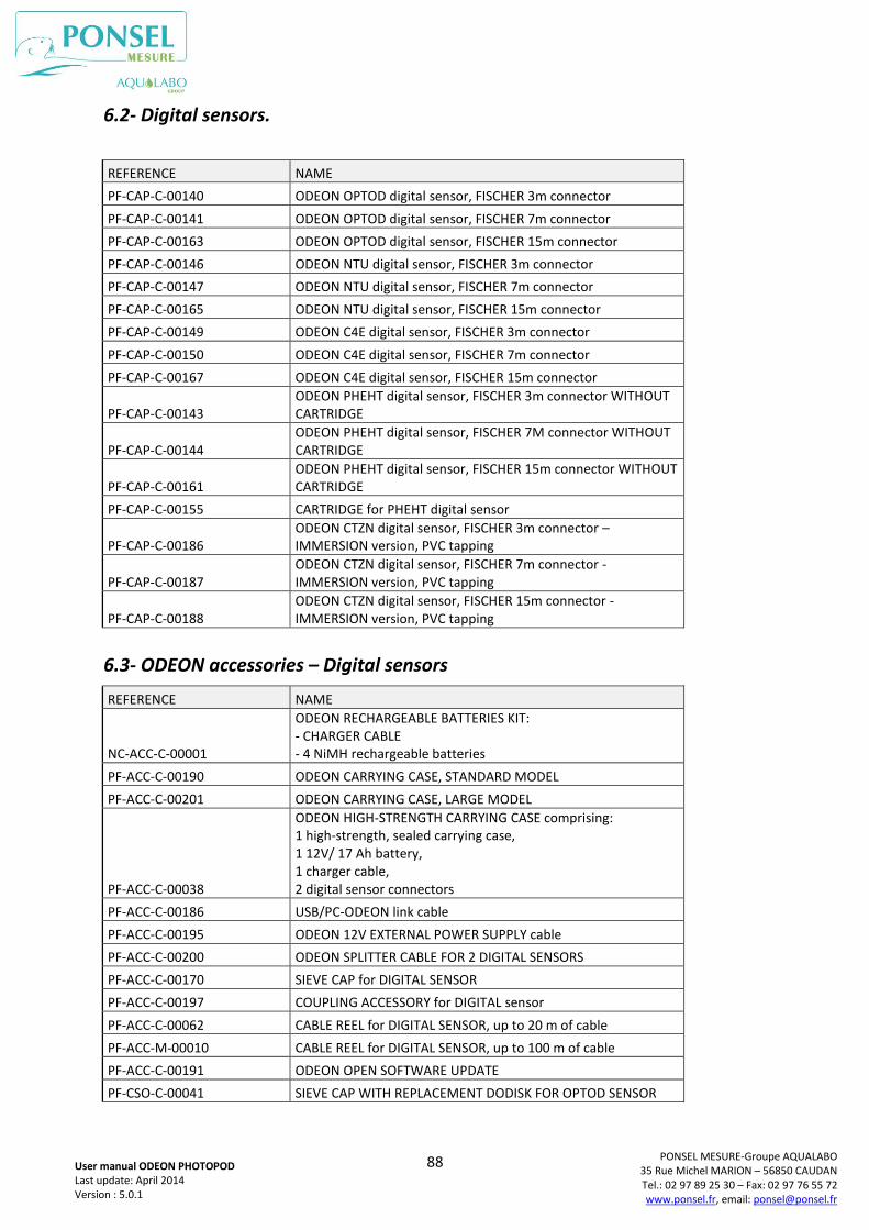
88
PONSEL MESURE-Groupe AQUALABO 35 Rue Michel MARION – 56850 CAUDAN Tel.: 02 97 89 25 30 – Fax: 02 97 76 55 72 www.ponsel.fr, email: [email protected]
User manual ODEON PHOTOPOD Last update: April 2014 Version : 5.0.1
6.2- Digital sensors.
REFERENCE NAME
PF-CAP-C-00140 ODEON OPTOD digital sensor, FISCHER 3m connector
PF-CAP-C-00141 ODEON OPTOD digital sensor, FISCHER 7m connector
PF-CAP-C-00163 ODEON OPTOD digital sensor, FISCHER 15m connector
PF-CAP-C-00146 ODEON NTU digital sensor, FISCHER 3m connector
PF-CAP-C-00147 ODEON NTU digital sensor, FISCHER 7m connector
PF-CAP-C-00165 ODEON NTU digital sensor, FISCHER 15m connector
PF-CAP-C-00149 ODEON C4E digital sensor, FISCHER 3m connector
PF-CAP-C-00150 ODEON C4E digital sensor, FISCHER 7m connector
PF-CAP-C-00167 ODEON C4E digital sensor, FISCHER 15m connector
PF-CAP-C-00143 ODEON PHEHT digital sensor, FISCHER 3m connector WITHOUT CARTRIDGE
PF-CAP-C-00144 ODEON PHEHT digital sensor, FISCHER 7M connector WITHOUT CARTRIDGE
PF-CAP-C-00161 ODEON PHEHT digital sensor, FISCHER 15m connector WITHOUT CARTRIDGE
PF-CAP-C-00155 CARTRIDGE for PHEHT digital sensor
PF-CAP-C-00186 ODEON CTZN digital sensor, FISCHER 3m connector – IMMERSION version, PVC tapping
PF-CAP-C-00187 ODEON CTZN digital sensor, FISCHER 7m connector - IMMERSION version, PVC tapping
PF-CAP-C-00188 ODEON CTZN digital sensor, FISCHER 15m connector - IMMERSION version, PVC tapping
6.3- ODEON accessories – Digital sensors
REFERENCE NAME
NC-ACC-C-00001
ODEON RECHARGEABLE BATTERIES KIT: - CHARGER CABLE - 4 NiMH rechargeable batteries
PF-ACC-C-00190 ODEON CARRYING CASE, STANDARD MODEL
PF-ACC-C-00201 ODEON CARRYING CASE, LARGE MODEL
PF-ACC-C-00038
ODEON HIGH-STRENGTH CARRYING CASE comprising: 1 high-strength, sealed carrying case, 1 12V/ 17 Ah battery, 1 charger cable, 2 digital sensor connectors
PF-ACC-C-00186 USB/PC-ODEON link cable
PF-ACC-C-00195 ODEON 12V EXTERNAL POWER SUPPLY cable
PF-ACC-C-00200 ODEON SPLITTER CABLE FOR 2 DIGITAL SENSORS
PF-ACC-C-00170 SIEVE CAP for DIGITAL SENSOR
PF-ACC-C-00197 COUPLING ACCESSORY for DIGITAL sensor
PF-ACC-C-00062 CABLE REEL for DIGITAL SENSOR, up to 20 m of cable
PF-ACC-M-00010 CABLE REEL for DIGITAL SENSOR, up to 100 m of cable
PF-ACC-C-00191 ODEON OPEN SOFTWARE UPDATE
PF-CSO-C-00041 SIEVE CAP WITH REPLACEMENT DODISK FOR OPTOD SENSOR
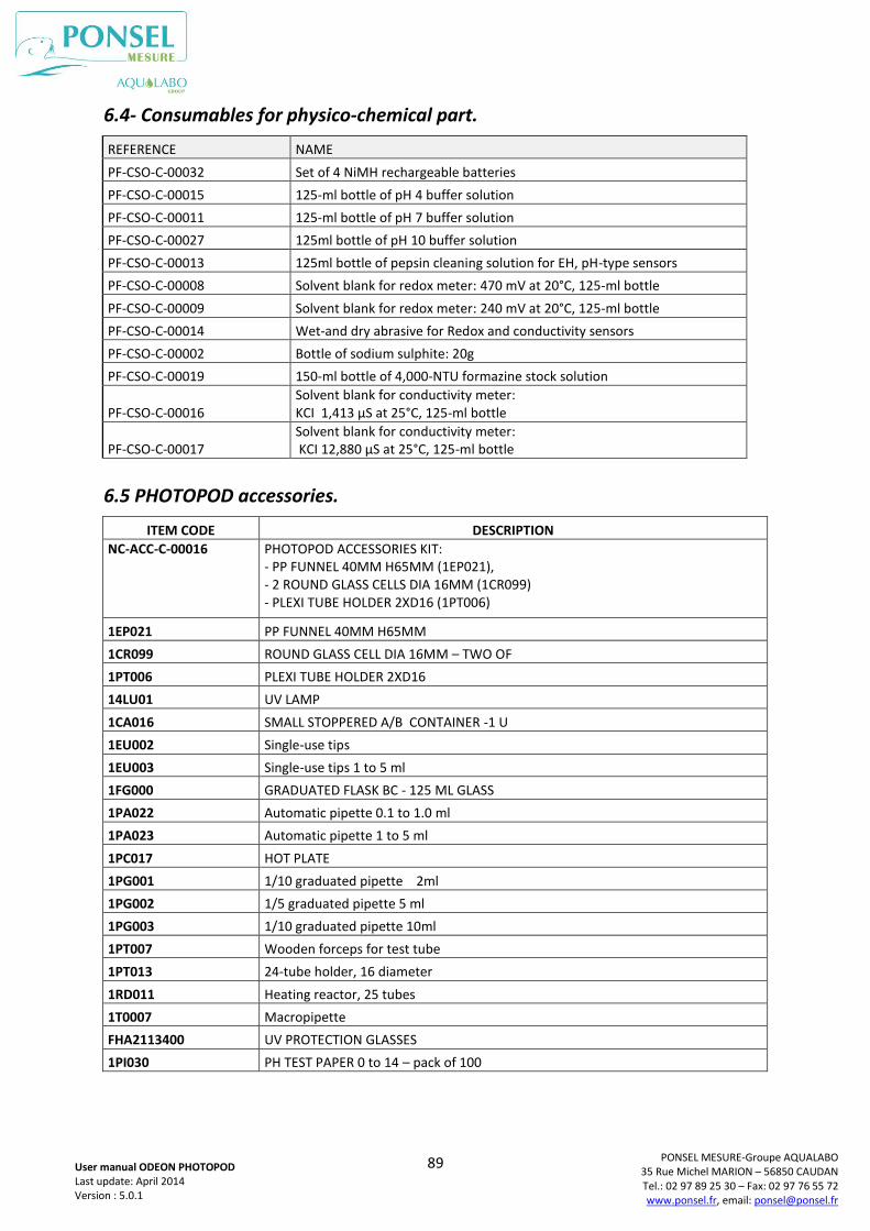
89
PONSEL MESURE-Groupe AQUALABO 35 Rue Michel MARION – 56850 CAUDAN Tel.: 02 97 89 25 30 – Fax: 02 97 76 55 72 www.ponsel.fr, email: [email protected]
User manual ODEON PHOTOPOD Last update: April 2014 Version : 5.0.1
6.4- Consumables for physico-chemical part.
REFERENCE NAME
PF-CSO-C-00032 Set of 4 NiMH rechargeable batteries
PF-CSO-C-00015 125-ml bottle of pH 4 buffer solution
PF-CSO-C-00011 125-ml bottle of pH 7 buffer solution
PF-CSO-C-00027 125ml bottle of pH 10 buffer solution
PF-CSO-C-00013 125ml bottle of pepsin cleaning solution for EH, pH-type sensors
PF-CSO-C-00008 Solvent blank for redox meter: 470 mV at 20°C, 125-ml bottle
PF-CSO-C-00009 Solvent blank for redox meter: 240 mV at 20°C, 125-ml bottle
PF-CSO-C-00014 Wet-and dry abrasive for Redox and conductivity sensors
PF-CSO-C-00002 Bottle of sodium sulphite: 20g
PF-CSO-C-00019 150-ml bottle of 4,000-NTU formazine stock solution
PF-CSO-C-00016 Solvent blank for conductivity meter: KCI 1,413 µS at 25°C, 125-ml bottle
PF-CSO-C-00017 Solvent blank for conductivity meter: KCI 12,880 µS at 25°C, 125-ml bottle
6.5 PHOTOPOD accessories.
ITEM CODE DESCRIPTION
NC-ACC-C-00016 PHOTOPOD ACCESSORIES KIT: - PP FUNNEL 40MM H65MM (1EP021), - 2 ROUND GLASS CELLS DIA 16MM (1CR099) - PLEXI TUBE HOLDER 2XD16 (1PT006)
1EP021 PP FUNNEL 40MM H65MM
1CR099 ROUND GLASS CELL DIA 16MM – TWO OF
1PT006 PLEXI TUBE HOLDER 2XD16
14LU01 UV LAMP
1CA016 SMALL STOPPERED A/B CONTAINER -1 U
1EU002 Single-use tips
1EU003 Single-use tips 1 to 5 ml
1FG000 GRADUATED FLASK BC - 125 ML GLASS
1PA022 Automatic pipette 0.1 to 1.0 ml
1PA023 Automatic pipette 1 to 5 ml
1PC017 HOT PLATE
1PG001 1/10 graduated pipette 2ml
1PG002 1/5 graduated pipette 5 ml
1PG003 1/10 graduated pipette 10ml
1PT007 Wooden forceps for test tube
1PT013 24-tube holder, 16 diameter
1RD011 Heating reactor, 25 tubes
1T0007 Macropipette
FHA2113400 UV PROTECTION GLASSES
1PI030 PH TEST PAPER 0 to 14 – pack of 100
90
PONSEL MESURE-Groupe AQUALABO 35 Rue Michel MARION – 56850 CAUDAN Tel.: 02 97 89 25 30 – Fax: 02 97 76 55 72 www.ponsel.fr, email: [email protected]
User manual ODEON PHOTOPOD Last update: April 2014 Version : 5.0.1
Technical Services
PONSEL MESURE – AQUALABO Group
35 Rue Michel MARION
56850 CAUDAN
Tel.: +33 (0)2.97.89.25.30
Fax: +33 (0)2.97.76.55.72
email: [email protected]
Sales department for ordering reagents
ORCHIDIS Laboratoire – AQUALABO Group
90 Rue du Professeur Paul Milliez
94506 CHAMPIGNY SUR MARNE
Tel.: +33 (0)1.55.09.10.10
Fax: +33 (0)1.55.09.10.39
email: [email protected]