OCM-101 & OCM-102 Modbus Option Module - Indelac … & OCM-102 Modbus Option Module Page 2...
20
OCM-101 & OCM-102 Modbus Option Module TELEPHONE: +1-859-727-7890 TOLL FREE: +1-800-662-9424 FAX: +1-859-727-4070 E-MAIL: [email protected] [email protected] [email protected] SHIPPING ADDRESS: 6810 POWERLINE DR.-FLORENCE, KY. 41042 VISIT OUR WEBSITE AT WWW.INDELAC.COM
Transcript of OCM-101 & OCM-102 Modbus Option Module - Indelac … & OCM-102 Modbus Option Module Page 2...

OCM-101 & OCM-102
Modbus Option Module
TELEPHONE: +1-859-727-7890 TOLL FREE: +1-800-662-9424 FAX: +1-859-727-4070 E-MAIL: [email protected]
[email protected] [email protected]
SHIPPING ADDRESS: 6810 POWERLINE DR.-FLORENCE, KY. 41042
VISIT OUR WEBSITE AT WWW.INDELAC.COM
OCM-101 & OCM-102 Modbus Option Module
Page 2
INTRODUCTION:
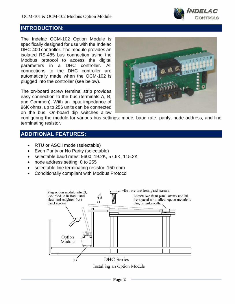
The Indelac OCM-102 Option Module is specifically designed for use with the Indelac DHC-400 controller. The module provides an isolated RS-485 bus connection using the Modbus protocol to access the digital parameters in a DHC controller. All connections to the DHC controller are automatically made when the OCM-102 is plugged into the controller (see below).
The on-board screw terminal strip provides easy connection to the bus (terminals A, B, and Common). With an input impedance of 96K ohms, up to 256 units can be connected on the bus. On-board dip switches allow configuring the module for various bus settings: mode, baud rate, parity, node address, and line terminating resistor.
ADDITIONAL FEATURES:
RTU or ASCII mode (selectable)
Even Parity or No Parity (selectable)
selectable baud rates: 9600, 19.2K, 57.6K, 115.2K
node address setting: 0 to 255
selectable line terminating resistor: 150 ohm
Conditionally compliant with Modbus Protocol
OCM-101 & OCM-102 Modbus Option Module
Page 3
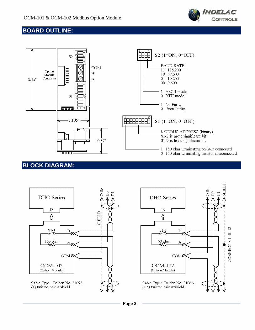
BOARD OUTLINE:
BLOCK DIAGRAM:
OCM-101 & OCM-102 Modbus Option Module
Page 4
DESCRIPTION:
The OCM-102 plugs into a DHC Series controller, making for easy installation. Power for the OCM-102 and all PACS® communication signals to the DHC controller are made through the Option Module Connector (see OUTLINE). The 3-pin screw terminal strip provides easy field wiring to the bus. S1 is a bank of 9 DIP switches that sets the unit's node address and can optionally connect the internal line terminating resistor. S2 is a bank of 4 DIP switches that configures the unit for the bus.
MODBUS CONNECTOR:
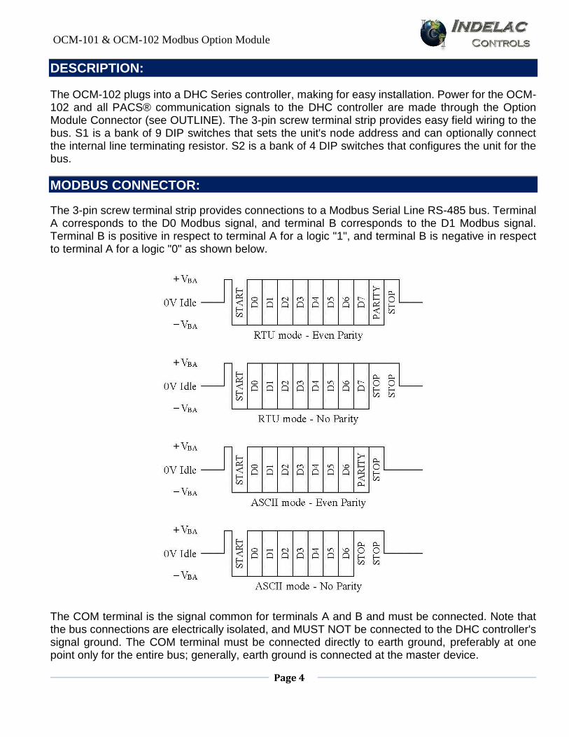
The 3-pin screw terminal strip provides connections to a Modbus Serial Line RS-485 bus. Terminal A corresponds to the D0 Modbus signal, and terminal B corresponds to the D1 Modbus signal. Terminal B is positive in respect to terminal A for a logic "1", and terminal B is negative in respect to terminal A for a logic "0" as shown below.
The COM terminal is the signal common for terminals A and B and must be connected. Note that the bus connections are electrically isolated, and MUST NOT be connected to the DHC controller's signal ground. The COM terminal must be connected directly to earth ground, preferably at one point only for the entire bus; generally, earth ground is connected at the master device.
OCM-101 & OCM-102 Modbus Option Module
Page 5
S1 - MODBUS ADDRESS and LT RESISTOR:
Setting S1-1 to the ON position connects the internal 150 ohm line terminating (LT) resistor between the A and B bus connections. Only units connected at each end of the bus should connect this resistor.
S1-2 to S1-9 set the Modbus node address. The switches represent the binary value of the desired address, where S1-2 is the most significant bit and S1-9 is the least significant bit. The ON position represents a logic "1", while the OFF position represents a logic "0".
The standard Modbus protocol reserves address 0 (all switches OFF) for broadcast commands. Also, addresses248 to 255 (switch settings 11111000 to 11111111) are reserved by the Modbus organization. Setting the switches to any of these addresses disables the OCM-102, which essentially removes the unit from the bus. If the address switches are changed while the bus is active, the OCM-102 will terminate any Modbus sequence in progress before accepting the new switch settings.
S2 - BAUD RATE, MODE, and PARITY:
Setting S2-1 OFF selects Even Parity checking. The parity bit (see Figure 1) should be "0" when the number of "1" bits in a given 8-bit byte (RTU mode) or 7-bit character (ASCII mode) is an even number. For an odd number of "1" bits, the parity bit should be "1". If the OCM-102 receives an incorrect parity bit value, no response will be given to the received command.
Setting S2-1 ON selects No Parity checking. The parity bit should be replaced with a logic "1" representing a second stop bit. If the OCM-102 receives a logic "0" in the parity position, no response will be given.
Setting S2-2 OFF selects the RTU mode, while setting S2-2 ON selects the ASCII mode. Refer to the appropriate sections for details on each mode.
S2-3 and S2-4 set the baud rate. Refer to OUTLINE for the available settings.
If any of the S2 switches are changed while the bus is active, the OCM-102 will terminate any Modbus sequence in progress before accepting the new switch settings.).
FUNCTIONAL DESCRIPTION:
The OCM-102 is a Modbus slave device addressable from 1 to 247. The OCM-102 communicates to the DHC controller via a PACS® Master port on the Option Module Connector (see OUTLINE). All connections and settings are automatically made when the OCM-102 is plugged into the DHC controller. The OCM-102 supports the functions listed below - all other functions are invalid and invoke an error response from the OCM-102. Refer to the specific section for details on each function.
OCM-101 & OCM-102 Modbus Option Module
Page 6
$03 Read Holding Registers
$06 Write Single Register
$08 Diagnostics
$41 PACS® (user defined)
The DHC controller is a PACS® Slave that is accessible using PACS® commands (see Appendix B) with the user defined function $41 (65 decimal), and is referred to here as the PACS® function. Upon receiving a function $41 command, the OCM-102 switches operation to a gateway that allows the user to directly communicate to the DHC controller.
Upon receiving a function $03 or $06 command, the OCM-102 switches operation to a Modbus interface. In this mode of operation, the OCM-102 maintains a virtual image of the DHC controller's parameters that allows fast access to these parameters using conventional Modbus commands. On power up, the OCM-102 defaults to the Modbus interface mode of operation.
Function $08 is strictly diagnostic and actually communicates to the OCM-102 rather than the DHC controller. Function $08 does not switch the mode of operation previously set by functions $03, $06, or $41.
PACS® MASTER:
The OCM-102 PACS® Master port communicates to the DHC controller's PACS® Slave port through the Option Module Connector. The OCM-102 maintains an off line timer that allows the DHC controller a limited amount of time to respond; this timer is set to 200msec when the OCM-102 powers up. If the OCM-102 detects an off line time out, it will send an error response with exception code $0B.
The off line timer value can be changed using Modbus Function $06 (Write Single Register). However, the changed value is lost if the OCM-102 loses power, and the value will need to be set again after power returns. To monitor the off line timer setting, the value can be read using Modbus Function $03 (Read Holding Registers).
MODBUS PROTOCOL:
The Modbus Protocol provides that only one master unit be connected to the bus. The master will always initiate any communications taking place on the bus, where the master issues a command (the Modbus Function) and then waits for the appropriate slave device, such as an OCM-102, to respond back. In the event the slave cannot or does not respond, the master will limit the amount of time to wait for a response, at which point it may initiate a new command to another slave.
To avoid conflicts on the bus, the master must allow a sufficient amount of time for the slave to perform its task and respond. When using the PACS® function $41, the OCM-102 will give a response within the PACS® off line timer value (see PACS® MASTER). When an initial off line time out is detected, a $0B exception response will be given at the end of the time out period. Once an off line time out is detected, the error response will be immediately given to subsequent requests from the bus until the OCM-102 corrects the detected PACS® error.
OCM-101 & OCM-102 Modbus Option Module
Page 7
When using functions $03, $06, and $08, the OCM-102 will provide an immediate response regardless of when an off line time out is detected. Once a time out is detected, a $0B exception response is returned until the OCM-102 corrects the detected PACS® error. Function $08 is not effected by a PACS® off line time out and will not return a $0B exception response.
Information on the bus is sent as a group of bytes (refer to Figure 1). For the RTU Mode, one byte consists of a start bit, 8 data bits (least significant bit sent first), a parity bit, and a stop bit. If No Parity is selected, the parity bit is replaced with an additional stop bit. For the ASCII Mode, one byte (also called a character) consists of a start bit, 7 data bits (least significant bit sent first), a parity bit, and a stop bit. If No Parity is selected, the parity bit is replaced with an additional stop bit.
APPLICATION DATA UNIT (ADU):
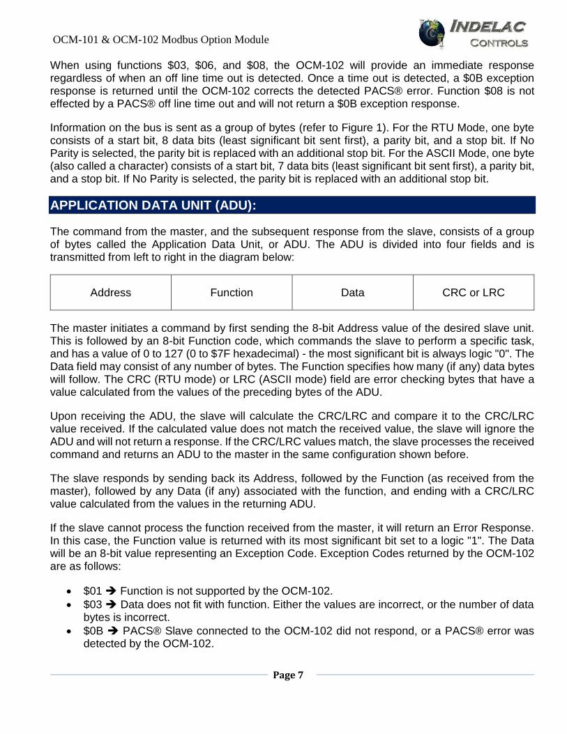
The command from the master, and the subsequent response from the slave, consists of a group of bytes called the Application Data Unit, or ADU. The ADU is divided into four fields and is transmitted from left to right in the diagram below:
Address Function Data CRC or LRC
The master initiates a command by first sending the 8-bit Address value of the desired slave unit. This is followed by an 8-bit Function code, which commands the slave to perform a specific task, and has a value of 0 to 127 (0 to $7F hexadecimal) - the most significant bit is always logic "0". The Data field may consist of any number of bytes. The Function specifies how many (if any) data bytes will follow. The CRC (RTU mode) or LRC (ASCII mode) field are error checking bytes that have a value calculated from the values of the preceding bytes of the ADU.
Upon receiving the ADU, the slave will calculate the CRC/LRC and compare it to the CRC/LRC value received. If the calculated value does not match the received value, the slave will ignore the ADU and will not return a response. If the CRC/LRC values match, the slave processes the received command and returns an ADU to the master in the same configuration shown before.
The slave responds by sending back its Address, followed by the Function (as received from the master), followed by any Data (if any) associated with the function, and ending with a CRC/LRC value calculated from the values in the returning ADU.
If the slave cannot process the function received from the master, it will return an Error Response. In this case, the Function value is returned with its most significant bit set to a logic "1". The Data will be an 8-bit value representing an Exception Code. Exception Codes returned by the OCM-102 are as follows:
$01 Function is not supported by the OCM-102.
$03 Data does not fit with function. Either the values are incorrect, or the number of data bytes is incorrect.
$0B PACS® Slave connected to the OCM-102 did not respond, or a PACS® error was detected by the OCM-102.
OCM-101 & OCM-102 Modbus Option Module
Page 8
If the received Address is equal to 0, representing a broadcast command, then the slave will process the command, but will not return a response. What task the slave performs in response to a broadcast command depends on the slave device and the Function received in the broadcast command.
The information in an ADU is transmitted on the bus in one of two modes: RTU (Remote Terminal Unit) or ASCII. The following sections describe each mode and the Modbus functions supported by the OCM-102.
RTU MODE:
In the RTU Mode, each byte is a sequence of 11 bits consisting of one start bit, 8 data bits, one parity bit, and one stop bit (see Figure 1). The time required for the 11 bit sequence is referred to as one character period, and is symbolized as t1. Since the baud rate setting dictates the number of bits per second, t1 will vary dependent on the baud rate. In this way, time relative to the baud rate is described. For example, t3.5 refers to the time required for 3.5 character periods.
The bus is considered to be idle if no transmission occurs on the bus for t3.5 or more. The first byte transmitted on the bus after a t3.5 period will be considered an Address byte, which marks the start of an ADU. The remaining bytes of the ADU must follow as a continuous stream with no more than t1.5 between each byte of the ADU.
If the OCM-102 detects a time longer than t1.5 between bytes of an ADU, the ADU will be considered invalid, and no response will be given. After detecting this type of error, the OCM-102 will then wait for a t3.5 idle period before accepting a new ADU. This means that any delinquent bytes of the error ADU are also ignored.
After receiving the Address byte, the second byte received will represent the Function. The number of Data bytes and what they represent is defined by the specific Function - refer to the appropriate section for details on the specific function. Following the Data bytes, two CRC bytes are received with the least significant byte received first. Refer to CRC CALCULATION for details on how the CRC bytes are calculated.
Once the OCM-102 detects the start of an ADU, it will accept all bytes until it detects a bus idle for t3.5 periods. At that time, the OCM-102 will process the received ADU if the received Address byte matches the address setting on S1. The ADU is also processed if the received Address is 0 (broadcast command), but no response will be given.
ASCII MODE:
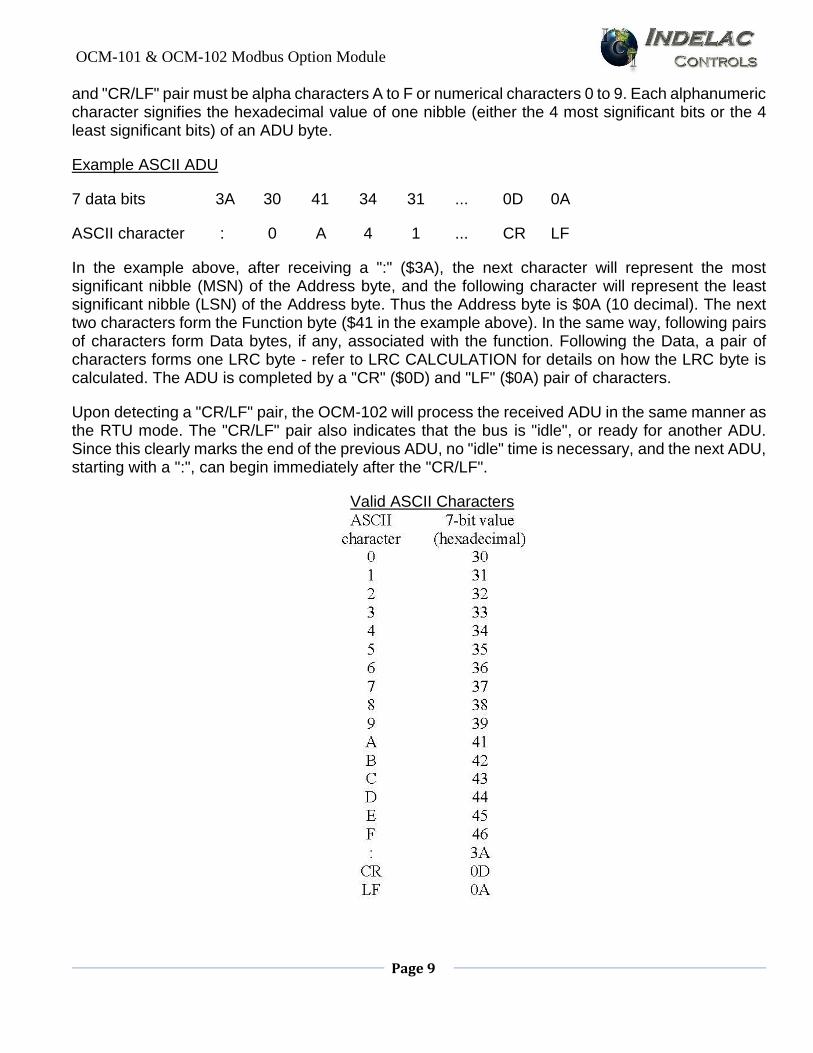
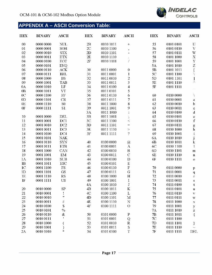
In the ASCII Mode, each byte is a sequence of 10 bits consisting of one start bit, 7 data bits, one parity bit, and one stop bit (see Figure 1). The seven data bits represent an ASCII character. While seven data bits can represent 128 different characters, only a limited set of characters are considered valid (see Table 1).
Of the valid characters, the ":" is used to signify the start of an ADU, and the "CR" (carriage return) and "LF" (line feed) are used to signify the end of an ADU. All characters received between the ":"
OCM-101 & OCM-102 Modbus Option Module
Page 9
and "CR/LF" pair must be alpha characters A to F or numerical characters 0 to 9. Each alphanumeric character signifies the hexadecimal value of one nibble (either the 4 most significant bits or the 4 least significant bits) of an ADU byte.
Example ASCII ADU
7 data bits 3A 30 41 34 31 ... 0D 0A
ASCII character : 0 A 4 1 ... CR LF
In the example above, after receiving a ":" ($3A), the next character will represent the most significant nibble (MSN) of the Address byte, and the following character will represent the least significant nibble (LSN) of the Address byte. Thus the Address byte is $0A (10 decimal). The next two characters form the Function byte ($41 in the example above). In the same way, following pairs of characters form Data bytes, if any, associated with the function. Following the Data, a pair of characters forms one LRC byte - refer to LRC CALCULATION for details on how the LRC byte is calculated. The ADU is completed by a "CR" ($0D) and "LF" ($0A) pair of characters.
Upon detecting a "CR/LF" pair, the OCM-102 will process the received ADU in the same manner as the RTU mode. The "CR/LF" pair also indicates that the bus is "idle", or ready for another ADU. Since this clearly marks the end of the previous ADU, no "idle" time is necessary, and the next ADU, starting with a ":", can begin immediately after the "CR/LF".
Valid ASCII Characters
OCM-101 & OCM-102 Modbus Option Module
Page 10
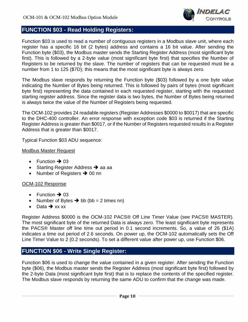
FUNCTION $03 - Read Holding Registers:
Function $03 is used to read a number of contiguous registers in a Modbus slave unit, where each register has a specific 16 bit (2 bytes) address and contains a 16 bit value. After sending the Function byte ($03), the Modbus master sends the Starting Register Address (most significant byte first). This is followed by a 2-byte value (most significant byte first) that specifies the Number of Registers to be returned by the slave. The number of registers that can be requested must be a number from 1 to 125 ($7D); this means that the most significant byte is always zero.
The Modbus slave responds by returning the Function byte ($03) followed by a one byte value indicating the Number of Bytes being returned. This is followed by pairs of bytes (most significant byte first) representing the data contained in each requested register, starting with the requested starting register address. Since the register data is two bytes, the Number of Bytes being returned is always twice the value of the Number of Registers being requested.
The OCM-102 provides 24 readable registers (Register Addresses $0000 to $0017) that are specific to the DHC-400 controller. An error response with exception code $03 is returned if the Starting Register Address is greater than $0017, or if the Number of Registers requested results in a Register Address that is greater than $0017.
Typical Function $03 ADU sequence:
Modbus Master Request
Function 03
Starting Register Address aa aa
Number of Registers 00 nn
OCM-102 Response
Function 03
Number of Bytes bb (bb = 2 times nn)
Data xx xx
Register Address $0000 is the OCM-102 PACS® Off Line Timer Value (see PACS® MASTER). The most significant byte of the returned Data is always zero. The least significant byte represents the PACS® Master off line time out period in 0.1 second increments. So, a value of 26 ($1A) indicates a time out period of 2.6 seconds. On power up, the OCM-102 automatically sets the Off Line Timer Value to 2 (0.2 seconds). To set a different value after power up, use Function $06.
FUNCTION $06 - Write Single Register:
Function $06 is used to change the value contained in a given register. After sending the Function byte ($06), the Modbus master sends the Register Address (most significant byte first) followed by the 2-byte Data (most significant byte first) that is to replace the contents of the specified register. The Modbus slave responds by returning the same ADU to confirm that the change was made.
OCM-101 & OCM-102 Modbus Option Module
Page 11
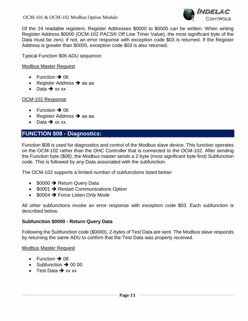
Of the 24 readable registers, Register Addresses $0000 to $0005 can be written. When writing Register Address $0000 (OCM-102 PACS® Off Line Timer Value), the most significant byte of the Data must be zero; if not, an error response with exception code $03 is returned. If the Register Address is greater than $0005, exception code $03 is also returned.
Typical Function $06 ADU sequence:
Modbus Master Request
Function 06
Register Address aa aa
Data xx xx
OCM-102 Response
Function 06
Register Address aa aa
Data xx xx
FUNCTION $08 - Diagnostics:
Function $08 is used for diagnostics and control of the Modbus slave device. This function operates on the OCM-102 rather than the DHC Controller that is connected to the OCM-102. After sending the Function byte ($08), the Modbus master sends a 2-byte (most significant byte first) Subfunction code. This is followed by any Data associated with the subfunction.
The OCM-102 supports a limited number of subfunctions listed below:
$0000 Return Query Data
$0001 Restart Communications Option
$0004 Force Listen Only Mode
All other subfunctions invoke an error response with exception code $03. Each subfunction is described below.
Subfunction $0000 - Return Query Data
Following the Subfunction code ($0000), 2-bytes of Test Data are sent. The Modbus slave responds by returning the same ADU to confirm that the Test Data was properly received.
Modbus Master Request
Function 08
Subfunction 00 00
Test Data xx xx
OCM-101 & OCM-102 Modbus Option Module
Page 12
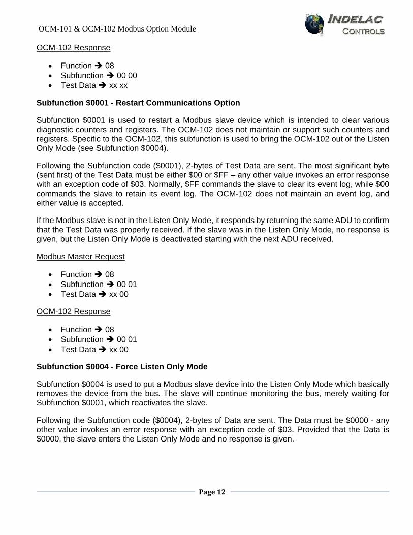
OCM-102 Response
Function 08
Subfunction 00 00
Test Data xx xx
Subfunction $0001 - Restart Communications Option
Subfunction $0001 is used to restart a Modbus slave device which is intended to clear various diagnostic counters and registers. The OCM-102 does not maintain or support such counters and registers. Specific to the OCM-102, this subfunction is used to bring the OCM-102 out of the Listen Only Mode (see Subfunction $0004).
Following the Subfunction code ($0001), 2-bytes of Test Data are sent. The most significant byte (sent first) of the Test Data must be either $00 or $FF – any other value invokes an error response with an exception code of $03. Normally, $FF commands the slave to clear its event log, while $00 commands the slave to retain its event log. The OCM-102 does not maintain an event log, and either value is accepted.
If the Modbus slave is not in the Listen Only Mode, it responds by returning the same ADU to confirm that the Test Data was properly received. If the slave was in the Listen Only Mode, no response is given, but the Listen Only Mode is deactivated starting with the next ADU received.
Modbus Master Request
Function 08
Subfunction 00 01
Test Data xx 00
OCM-102 Response
Function 08
Subfunction 00 01
Test Data xx 00
Subfunction $0004 - Force Listen Only Mode
Subfunction $0004 is used to put a Modbus slave device into the Listen Only Mode which basically removes the device from the bus. The slave will continue monitoring the bus, merely waiting for Subfunction $0001, which reactivates the slave.
Following the Subfunction code ($0004), 2-bytes of Data are sent. The Data must be $0000 - any other value invokes an error response with an exception code of $03. Provided that the Data is $0000, the slave enters the Listen Only Mode and no response is given.
OCM-101 & OCM-102 Modbus Option Module
Page 13
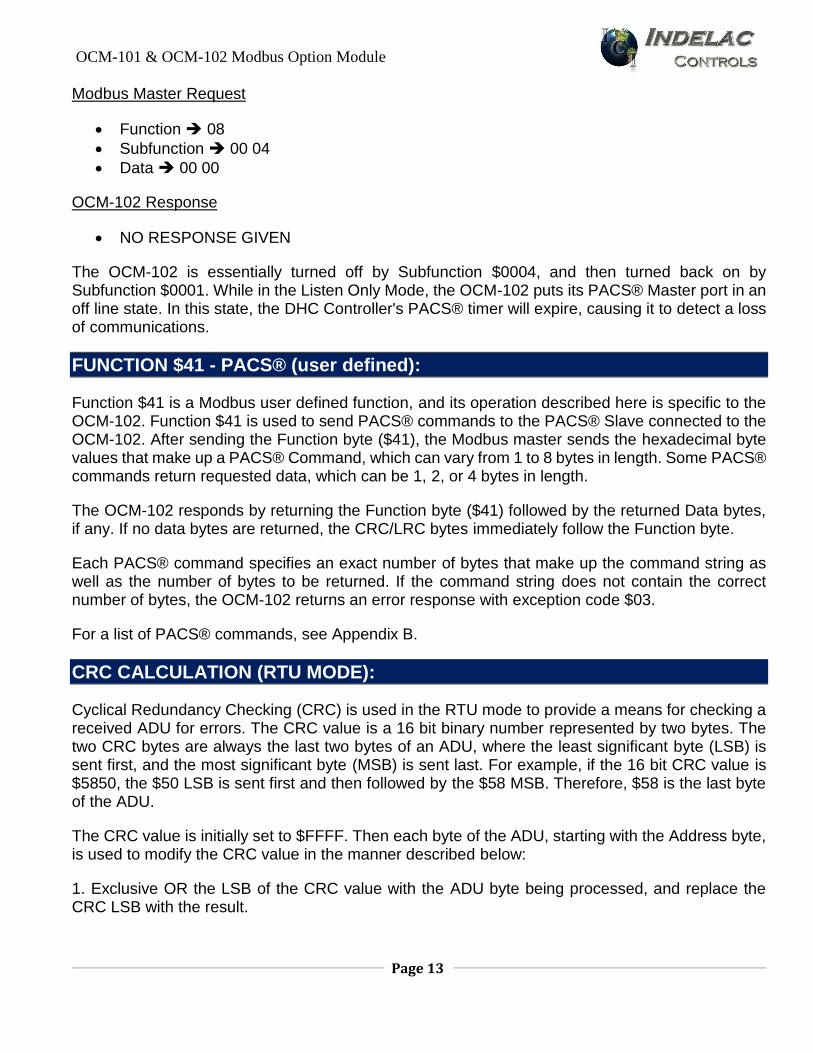
Modbus Master Request
Function 08
Subfunction 00 04
Data 00 00
OCM-102 Response
NO RESPONSE GIVEN
The OCM-102 is essentially turned off by Subfunction $0004, and then turned back on by Subfunction $0001. While in the Listen Only Mode, the OCM-102 puts its PACS® Master port in an off line state. In this state, the DHC Controller's PACS® timer will expire, causing it to detect a loss of communications.
FUNCTION $41 - PACS® (user defined):
Function $41 is a Modbus user defined function, and its operation described here is specific to the OCM-102. Function $41 is used to send PACS® commands to the PACS® Slave connected to the OCM-102. After sending the Function byte ($41), the Modbus master sends the hexadecimal byte values that make up a PACS® Command, which can vary from 1 to 8 bytes in length. Some PACS® commands return requested data, which can be 1, 2, or 4 bytes in length.
The OCM-102 responds by returning the Function byte ($41) followed by the returned Data bytes, if any. If no data bytes are returned, the CRC/LRC bytes immediately follow the Function byte.
Each PACS® command specifies an exact number of bytes that make up the command string as well as the number of bytes to be returned. If the command string does not contain the correct number of bytes, the OCM-102 returns an error response with exception code $03.
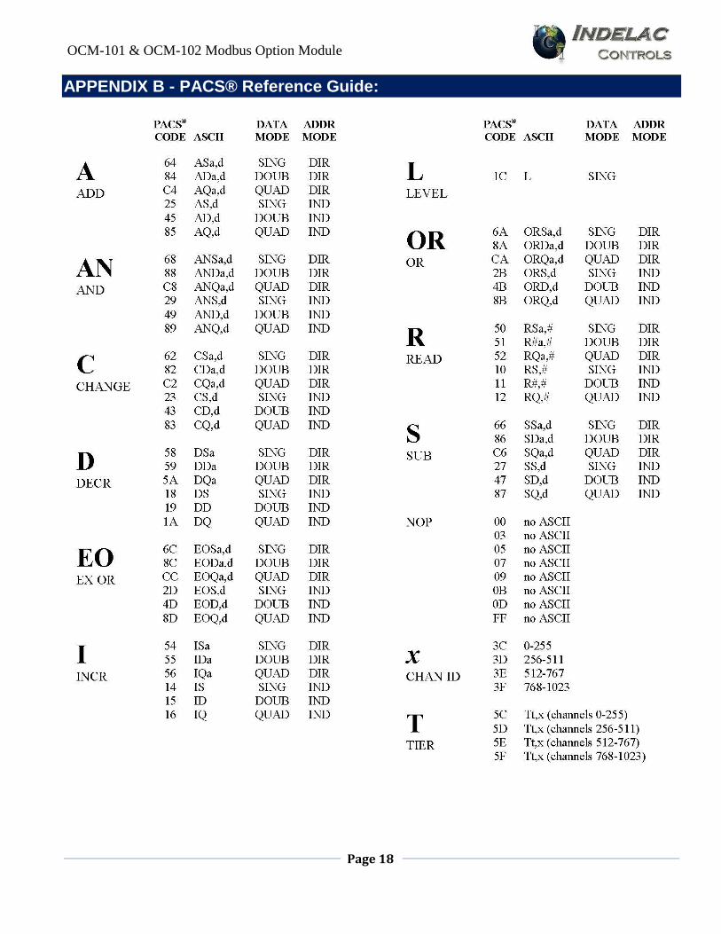
For a list of PACS® commands, see Appendix B.
CRC CALCULATION (RTU MODE):
Cyclical Redundancy Checking (CRC) is used in the RTU mode to provide a means for checking a received ADU for errors. The CRC value is a 16 bit binary number represented by two bytes. The two CRC bytes are always the last two bytes of an ADU, where the least significant byte (LSB) is sent first, and the most significant byte (MSB) is sent last. For example, if the 16 bit CRC value is $5850, the $50 LSB is sent first and then followed by the $58 MSB. Therefore, $58 is the last byte of the ADU.
The CRC value is initially set to $FFFF. Then each byte of the ADU, starting with the Address byte, is used to modify the CRC value in the manner described below:
1. Exclusive OR the LSB of the CRC value with the ADU byte being processed, and replace the CRC LSB with the result.

OCM-101 & OCM-102 Modbus Option Module
Page 14
2. If the least significant bit of the new CRC value is "0", shift the 16 bit CRC value one bit to the right, setting the most significant bit to "0".
If the least significant bit of the new CRC value is "1", shift the 16 bit CRC value one bit to the right, setting the most significant bit to "0". Then exclusive OR the shifted 16 bit CRC value with the 16 bit constant $A001, and replace the CRC value with the result.
3. Repeat step 2 seven times.
The modified CRC value resulting from the above, is then further modified in the same way by each of the remaining bytes of the ADU. The following example illustrates the calculation.
Modbus Master Requesting ADU
05 41 1C 50 58
where: $05 is slave Address 5
$41 is PACS® Function
$1C is PACS® LEVEL command
$5850 is CRC value
The CRC value is calculated as follows:
$FFFF initial CRC value
$437F modify CRC with $05
$D0C2 further modify CRC with $41
$5850 further modify CRC with $1C
OCM-102(address 5) Responding ADU
05 41 01 90 51
where: $05 is slave Address 5
$41 is PACS® Function
$01 is level of PACS® Slave
$5190 is CRC value
The CRC value is calculated as follows:
$FFFF initial CRC value
$437F modify CRC with $05
$D0C2 further modify CRC with $41
$5190 further modify CRC with $01
OCM-101 & OCM-102 Modbus Option Module
Page 15
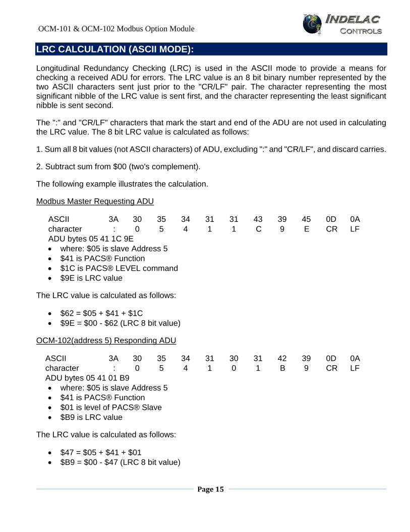
LRC CALCULATION (ASCII MODE):
Longitudinal Redundancy Checking (LRC) is used in the ASCII mode to provide a means for checking a received ADU for errors. The LRC value is an 8 bit binary number represented by the two ASCII characters sent just prior to the "CR/LF" pair. The character representing the most significant nibble of the LRC value is sent first, and the character representing the least significant nibble is sent second.
The ":" and "CR/LF" characters that mark the start and end of the ADU are not used in calculating the LRC value. The 8 bit LRC value is calculated as follows:
1. Sum all 8 bit values (not ASCII characters) of ADU, excluding ":" and "CR/LF", and discard carries.
2. Subtract sum from $00 (two's complement).
The following example illustrates the calculation.
Modbus Master Requesting ADU
ASCII 3A 30 35 34 31 31 43 39 45 0D 0A
character : 0 5 4 1 1 C 9 E CR LF
ADU bytes 05 41 1C 9E
where: $05 is slave Address 5
$41 is PACS® Function
$1C is PACS® LEVEL command
$9E is LRC value
The LRC value is calculated as follows:
$62 = $05 + $41 + $1C
$9E = $00 - $62 (LRC 8 bit value)
OCM-102(address 5) Responding ADU
ASCII 3A 30 35 34 31 30 31 42 39 0D 0A
character : 0 5 4 1 0 1 B 9 CR LF
ADU bytes 05 41 01 B9
where: $05 is slave Address 5
$41 is PACS® Function
$01 is level of PACS® Slave
$B9 is LRC value
The LRC value is calculated as follows:
$47 = $05 + $41 + $01
$B9 = $00 - $47 (LRC 8 bit value)
OCM-101 & OCM-102 Modbus Option Module
Page 16
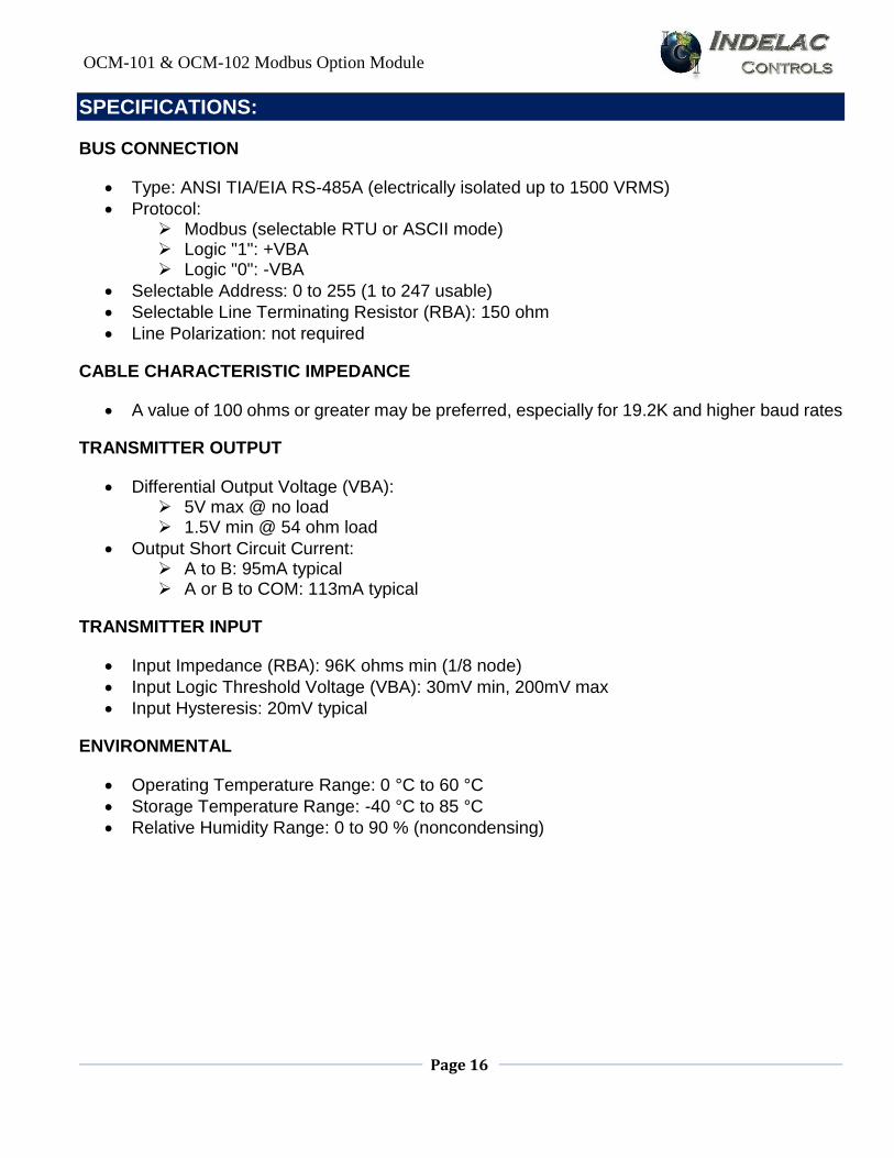
SPECIFICATIONS:
BUS CONNECTION
Type: ANSI TIA/EIA RS-485A (electrically isolated up to 1500 VRMS)
Protocol: Modbus (selectable RTU or ASCII mode) Logic "1": +VBA Logic "0": -VBA
Selectable Address: 0 to 255 (1 to 247 usable)
Selectable Line Terminating Resistor (RBA): 150 ohm
Line Polarization: not required
CABLE CHARACTERISTIC IMPEDANCE
A value of 100 ohms or greater may be preferred, especially for 19.2K and higher baud rates
TRANSMITTER OUTPUT
Differential Output Voltage (VBA): 5V max @ no load 1.5V min @ 54 ohm load
Output Short Circuit Current: A to B: 95mA typical A or B to COM: 113mA typical
TRANSMITTER INPUT
Input Impedance (RBA): 96K ohms min (1/8 node)
Input Logic Threshold Voltage (VBA): 30mV min, 200mV max
Input Hysteresis: 20mV typical
ENVIRONMENTAL
Operating Temperature Range: 0 °C to 60 °C
Storage Temperature Range: -40 °C to 85 °C
Relative Humidity Range: 0 to 90 % (noncondensing)
OCM-101 & OCM-102 Modbus Option Module
Page 17
APPENDIX A – ASCII Conversion Table:
OCM-101 & OCM-102 Modbus Option Module
Page 18
APPENDIX B - PACS® Reference Guide:
OCM-101 & OCM-102 Modbus Option Module
Page 19
NOTES
_________________________________________________________________
_________________________________________________________________
_________________________________________________________________
_________________________________________________________________
_________________________________________________________________
_________________________________________________________________
_________________________________________________________________
_________________________________________________________________
_________________________________________________________________
_________________________________________________________________
_________________________________________________________________
_________________________________________________________________
_________________________________________________________________
_________________________________________________________________
_________________________________________________________________
_________________________________________________________________
_________________________________________________________________
_________________________________________________________________
_________________________________________________________________
_________________________________________________________________
_________________________________________________________________
_________________________________________________________________
_________________________________________________________________
_________________________________________________________________
_________________________________________________________________
_________________________________________________________________
_________________________________________________________________
_________________________________________________________________
_________________________________________________________________
_________________________________________________________________
_________________________________________________________________

OCM-101 & OCM-102 Modbus Option Module
Page 20
Contact Information
Debbie Voges [email protected] 859-727-7890 ext. 100
Matt Robinson [email protected] 859-727-7890 ext. 109
Talbot Caywood [email protected] 859-727-7890 ext. 110
For News & Updates, Check Out Our Blog: www.blog.indelac.com


![Crystia WAKASAGI CRTa CRT + CRT 7-.»nxwn F203-8511 TEL : … · 1 OOcmFl-fZ 1 OOcm 30Cm b 5cmï B 12 73-- 7-» 1 Ocm 1 Ocm 1 Ocm 1 Ocm Ocm @ (CRTa/CRT+/CRT 10.8m r 10.0] aŽ3Y5-10.om](https://static.fdocuments.net/doc/165x107/6111874afc42b616e8749307/crystia-wakasagi-crta-crt-crt-7-nxwn-f203-8511-tel-1-oocmfl-fz-1-oocm-30cm.jpg)