Ocean Systems Test and Evaluation Program (OSTEP ... · PDF fileOcean Systems Test and...
42
NOAA Technical Report NOS CO-OPS 34 Ocean Systems Test and Evaluation Program (OSTEP) Development Plan Silver Spring, Maryland April 2001 noaa National Oceanic and Atmospheric Administration U.S. DEPARTMENT OF COMMERCE National Ocean Service Center for Operational Oceanographic Products and Services
Transcript of Ocean Systems Test and Evaluation Program (OSTEP ... · PDF fileOcean Systems Test and...
NOAA Technical Report NOS CO-OPS 34
Ocean Systems Test and Evaluation Program (OSTEP)Development Plan
Silver Spring, MarylandApril 2001
noaa National Oceanic and Atmospheric Administration
U.S. DEPARTMENT OF COMMERCENational Ocean ServiceCenter for Operational Oceanographic Products and Services
Center for Operational Oceanographic Products and ServicesNational Ocean Service
National Oceanic and Atmospheric AdministrationU.S. Department of Commerce
The National Ocean Service (NOS) Center for Operational Oceanographic Products andServices (CO-OPS) collects and distributes observations and predictions of water levels andcurrents to ensure safe, efficient and environmentally sound maritime commerce. The Centerprovides the set of water level and coastal current products required to support NOS'Strategic Plan mission requirements, and to assist in providing operational oceanographicdata/products required by NOAA's other Strategic Plan themes. The Center manages theNational Water Level Observation Network (NWLON), and a national network of PhysicalOceanographic Real-Time Systems (PORTS™) in major U.S. harbors. The Center:establishes standards for the collection and processing of water level and current data;collects and documents user requirements which serve as the foundation for all resultingprogram activities; designs new and/or improved oceanographic observing systems; designssoftware to improve CO-OPS' data processing capabilities; maintains and operatesoceanographic observing systems; performs operational data analysis/quality control; andproduces/disseminates oceanographic products.
NOAA Technical Report NOS CO-OPS 34
Ocean Systems Test and Evaluation Program (OSTEP)Development Plan
Mark Bushnell
April 2001
noaa National Oceanic and Atmospheric Administration
U.S. DEPARTMENT OF COMMERCE National Oceanic and Atmospheric Administration
Don Evans, Secretary Scott B. Gudes, Acting Under Secretary for Oceans and
Atmosphere and NOAA Administrator
National Ocean Service
Margaret A. Davidson, Acting Assistant Administrator
for Ocean Services and Coastal Zone Management
Center for Operational Oceanographic Products and Services
Michael Szabados, Acting Director
NOTICE
Mention of a commercial company or product does not constitute anendorsement by NOAA. Use for publicity or advertising purposes ofinformation from this publication concerning proprietary products orthe tests of such products is not authorized.
iii
Table of Content
EXECUTIVE SUMMARY . . . . . . . . . . . . . . . . . . . . . . . . . . . . . . . . . . . . . . . . . . . . . . . . . . . . v
1.0 INTRODUCTION . . . . . . . . . . . . . . . . . . . . . . . . . . . . . . . . . . . . . . . . . . . . . . . . . . . . . . . . 11.1 Purpose of Document . . . . . . . . . . . . . . . . . . . . . . . . . . . . . . . . . . . . . . . . . . . . . . . . . 11.2 CO-OPS Mission Statement . . . . . . . . . . . . . . . . . . . . . . . . . . . . . . . . . . . . . . . . . . . 11.3 Background . . . . . . . . . . . . . . . . . . . . . . . . . . . . . . . . . . . . . . . . . . . . . . . . . . . . . . . . 1
1.3.1 National Water Level Observation Network . . . . . . . . . . . . . . . . . . . . . . . . . . 11.3.2 National Physical Oceanographic Real-Time System . . . . . . . . . . . . . . . . . . . 2
1.4 Goals & Objectives of an Ocean System Test & Evaluation Program . . . . . . . . . . . 21.4.1 Evaluation of New Technology for Use in Programs . . . . . . . . . . . . . . . . . . . 31.4.2 Integration & Test of Systems Under Development . . . . . . . . . . . . . . . . . . . . 31.4.3 Development Test & Evaluation . . . . . . . . . . . . . . . . . . . . . . . . . . . . . . . . . . . 31.4.4 Life cycle Evaluation of Systems . . . . . . . . . . . . . . . . . . . . . . . . . . . . . . . . . . 4
1.5 Partners . . . . . . . . . . . . . . . . . . . . . . . . . . . . . . . . . . . . . . . . . . . . . . . . . . . . . . . . . . . 41.5.1 Old Dominion University, CCPO . . . . . . . . . . . . . . . . . . . . . . . . . . . . . . . . . . 41.5.2 National Institute of Standards & Technology . . . . . . . . . . . . . . . . . . . . . . . . 41.5.3 Naval Surface Warfare Center, Carderock Division . . . . . . . . . . . . . . . . . . . . 41.5.4 Other Potentially Interested Entities . . . . . . . . . . . . . . . . . . . . . . . . . . . . . . . . 5
1.6 Relationship to Other Test Facilities . . . . . . . . . . . . . . . . . . . . . . . . . . . . . . . . . . . . . 51.6.1 Field Research Center - US Army Corps of Engineers . . . . . . . . . . . . . . . . . . 51.6.2 NWS/NDBC . . . . . . . . . . . . . . . . . . . . . . . . . . . . . . . . . . . . . . . . . . . . . . . . . . 6
2.0 REQUIREMENTS . . . . . . . . . . . . . . . . . . . . . . . . . . . . . . . . . . . . . . . . . . . . . . . . . . . . . . . 72.1 CO-OPS Data Quality Assurance Requirements . . . . . . . . . . . . . . . . . . . . . . . . . . . . 72.2 National Water Level Network Requirements . . . . . . . . . . . . . . . . . . . . . . . . . . . . . . 72.3 National PORTS™ Program Requirements . . . . . . . . . . . . . . . . . . . . . . . . . . . . . . . 82.4 National Current Program Requirements . . . . . . . . . . . . . . . . . . . . . . . . . . . . . . . . . . 92.5 OSTEP Data Management & Network Requirements . . . . . . . . . . . . . . . . . . . . . . . . 92.6 Field Site Environmental Requirements . . . . . . . . . . . . . . . . . . . . . . . . . . . . . . . . . . 102.7 Test & Evaluation Plan Requirements . . . . . . . . . . . . . . . . . . . . . . . . . . . . . . . . . . . . 112.8 CO-OPS Information Systems Requirements . . . . . . . . . . . . . . . . . . . . . . . . . . . . . . 11
3.0 TECHNICAL APPROACH . . . . . . . . . . . . . . . . . . . . . . . . . . . . . . . . . . . . . . . . . . . . . . . . 133.1 ISO 25 Accreditation Process . . . . . . . . . . . . . . . . . . . . . . . . . . . . . . . . . . . . . . . . . . 133.2 Facility Organization & Staff Competencies . . . . . . . . . . . . . . . . . . . . . . . . . . . . . . . 143.3 Test & Evaluation Process and Planing . . . . . . . . . . . . . . . . . . . . . . . . . . . . . . . . . . . 143.4 Software Quality Assurance Process . . . . . . . . . . . . . . . . . . . . . . . . . . . . . . . . . . . . . 153.5 Total Quality Assurance Process . . . . . . . . . . . . . . . . . . . . . . . . . . . . . . . . . . . . . . . . 15
3.5.1 General Considerations . . . . . . . . . . . . . . . . . . . . . . . . . . . . . . . . . . . . . . . . . . 16
4.0 FACILITY MANAGEMENT . . . . . . . . . . . . . . . . . . . . . . . . . . . . . . . . . . . . . . . . . . . . . . 174.1 Facility Management Organization . . . . . . . . . . . . . . . . . . . . . . . . . . . . . . . . . . . . . . 17
iv
4.2 Facilities Description . . . . . . . . . . . . . . . . . . . . . . . . . . . . . . . . . . . . . . . . . . . . . . . . . 174.3 Test Equipment . . . . . . . . . . . . . . . . . . . . . . . . . . . . . . . . . . . . . . . . . . . . . . . . . . . . . 19
4.3.1 Field Oceanographic Reference Systems . . . . . . . . . . . . . . . . . . . . . . . . . . . . 194.4 Staff Position Descriptions . . . . . . . . . . . . . . . . . . . . . . . . . . . . . . . . . . . . . . . . . . . . 20
4.4.1 Technical Manager . . . . . . . . . . . . . . . . . . . . . . . . . . . . . . . . . . . . . . . . . . . . . 204.4.2 Quality Assurance Manager . . . . . . . . . . . . . . . . . . . . . . . . . . . . . . . . . . . . . . 204.4.3 Facility Operations Manager . . . . . . . . . . . . . . . . . . . . . . . . . . . . . . . . . . . . . . 204.4.4 T&E Staff . . . . . . . . . . . . . . . . . . . . . . . . . . . . . . . . . . . . . . . . . . . . . . . . . . . . 204.4.5 IT Staff . . . . . . . . . . . . . . . . . . . . . . . . . . . . . . . . . . . . . . . . . . . . . . . . . . . . . . . 20
4.5 Financial Management . . . . . . . . . . . . . . . . . . . . . . . . . . . . . . . . . . . . . . . . . . . . . . . . 214.6 Advisory Board . . . . . . . . . . . . . . . . . . . . . . . . . . . . . . . . . . . . . . . . . . . . . . . . . . . . . 21
5.0 REFERENCES . . . . . . . . . . . . . . . . . . . . . . . . . . . . . . . . . . . . . . . . . . . . . . . . . . . . . . . . 23
APPENDICES . . . . . . . . . . . . . . . . . . . . . . . . . . . . . . . . . . . . . . . . . . . . . . . . . . . . . . . . . . . . . . 25 I Schedule . . . . . . . . . . . . . . . . . . . . . . . . . . . . . . . . . . . . . . . . . . . . . . . . . . . . . . . . . . . 27II New Sensors . . . . . . . . . . . . . . . . . . . . . . . . . . . . . . . . . . . . . . . . . . . . . . . . . . . . . . . . 29III OSTEP Budget . . . . . . . . . . . . . . . . . . . . . . . . . . . . . . . . . . . . . . . . . . . . . . . . . . . . . . 31
v
EXECUTIVE SUMMARY
The burden on the Nation’s coastal ocean and waterways continues to grow at an acceleratingrate, while insufficient resources are available to adequately monitor even the most basicparameters. Advances in technology and communications systems offer a wide variety ofpotential solutions, also at an accelerating rate. The challenge is to introduce these newcapabilities into existing monitoring networks in a cost effective and responsible manner.
A variety of coastal programs are presently in the early stages of development. Through themthere here is a growing awareness of the value of existing infrastructure and the difficulty ofoperating permanent monitoring systems. NOS should be prepared to accept the logical demandfor additional sensors.
The OSTEP seeks to facilitate the transition of new technology to an operational status, selectingnewly developed sensors or systems from the research and development community and bringingthem to a monitoring setting. OSTEP will also provide quantifiable and defensible justificationsfor the use of existing sensors and methods for selecting new systems. The program will establishand maintain field reference facilities where, in cooperation with other agencies facing similarchallenges, devices will be examined in a non-operational field setting. Through OSTEP,sensors will be evaluated, quality control procedures developed, and maintenance routinesgenerated. The quality of the reference systems used in the field will be assured by both rigoroustraceable calibrations and redundant sensors.

vi
1
1.0 INTRODUCTION
1.1 Purpose of Document
This document is a plan for the development of an OSTEP and the establishment of an OceanSystems Test & Evaluation Facility (OSTEF) in Chesapeake, VA, in cooperation with the OldDominion University, the National Institute of Standards and Technology (NIST), and the NavalSurface Warfare Center/Carderock Division.
1.2 CO-OPS Mission Statement
The National Ocean Service (NOS) Center for Operational Oceanographic Products and Services(CO-OPS) collects and distributes observations and predictions of water levels and currents to ensuresafe, efficient and environmentally sound maritime commerce. The Center provides the set of waterlevel and coastal current products required to support NOS' Strategic Plan mission requirements, andto assist in providing operational oceanographic data/products required by NOAA's other StrategicPlan themes. For example, CO-OPS provides data and products required by the National WeatherService to meet its flood and tsunami warning responsibilities. The Center manages the NationalWater Level Observation Network (NWLON), and a national network of Physical OceanographicReal-Time Systems (PORTS™) in major U.S. harbors. The Center; establishes standards for thecollection and processing of water level and current data, collects and documents user requirementswhich serve as the foundation for all resulting program activities, designs new and/or improvedoceanographic observing systems, designs software to improve CO-OPS' data processingcapabilities, maintains and operates oceanographic observing systems, performs operational dataanalysis/quality control, and produces/disseminates oceanographic products.
The Center is divided into four Divisions to address various functionally important areas. Thedivisions are Requirements & Development, Field Operations, Products and Services, andInformation Systems.
1.3 Background
1.3.1 National Water Level Observation Network
CO-OPS is responsible for the management of the U.S. National Water Level Program (NWLP). Thefoundation of this program is the National Water Level Observation Network (NWLON), a networkof water level measurement stations in the U.S. coastal ocean, including the Great Lakes andconnecting waterways, and in U.S. Trust Territories and Possessions.
The data and information from the NWLON represent one of the most unique and valuablegeophysical data sets available. In addition to about 140 continuously operating NWLON stationsin U.S. tidal regions and 49 continuously operating stations in the Great Lakes, the Center operatesabout 50 temporary water level measurement stations each year in support of National Ocean Servicemapping and charting, hydrography, and Great Lakes water resources management. Several stationshave continuous data series starting in the mid and late 1800's. Data and information are availablefrom several thousand additional locations in the U.S. coastal ocean where shorter series of
2
observations have been collected. Networks of local bench marks maintained at each location areused to maintain and update vertical reference systems.
Using the foundation provided by the NWLON, the NWLP provides for the determination of andmaintenance of vertical reference datums used for surveying and mapping, dredging, and coastalconstruction, water level regulation, marine boundary determination, tide prediction, and for analysisof long-term water level variations and trends.
1.3.2 National Physical Oceanographic Real-Time System
The National PORTS™ provides observations and predictions of oceanographic and marinemeteorological conditions for decision support in which life and property are at risk. A legal liabilityfor the observations and predictions demands that PORTS™ provide information which is of the bestquality available. The measurement quality must support not only direct application of the data todecisions, but also derived products and services such as computer model simulations based onreal-time data assimilated into the model. Derived products and services place an additional levelof accuracy on the measurements obtained by PORTS™. PORTS™ measurements must be ofsufficient accuracy so that the derived products and services maintain the level of accuracy requiredfor decision support. For example, water levels generated by a nowcast model for real-timeunderkeel clearance applications must have a similar level of accuracy as the direct observations.
1.4 Goals & Objectives of an Ocean System Test & Evaluation Program
The goal of the Ocean Systems Test & Evaluation Program (OSTEP) is to provide a non-operationalsetting in which to test and evaluate oceanographic and marine meteorological sensors and systems.OSTEP will facilitate the introduction of new sensors into an operational setting by providing testdata quality assurance to a level required for NOS to accept legal liability for observations andderived navigation safety products and services.
There are five objectives of OSTEP:1) Evaluation of new technology for use in measurement systems;
2) Integration and testing of field measurement systems;
3) Development, test and evaluation to determine measurement system readiness foroperational deployment,
4) Life cycle evaluation of system performance, operations, and maintenance, and;
5) To provide and oversee the establishment of quality control parameters that will be used bythe Continuous Operational Real Time Monitoring System (CORMS).
OSTEP will provide three basic data quality assurance capabilities;
1) Measurement standards traceable to the NIST of sufficient accuracy in the field to determinean uncertainty budget for measurements used directly as observations and for hydrodynamicmodel predictions,
3
2) Legally identifiable independent organization and management with the authority andresources needed to meet the goal; and
3) A quality process appropriate to the type, range and volume of calibration and testingactivities to meet the most demanding CO-OPS product and service quality assurancerequirements.
CO-OPS will provide the capability through partnerships, including: 1) existing and continuingcontracts with the Naval Surface Warfare Center/Carderock Division, 2) the Cooperative Institutefor Coastal Physical Oceanography recently formed with the Old Dominion University, and3) planned participation in the National Voluntary Laboratory Accreditation Program (NVLAP)operated by the NIST. OSTEP will be accredited against ISO 25 standards under the NIST NVLAPto ensure that the three capabilities are continuously improved to meet evolving programrequirements.
1.4.1 Evaluation of New Technology for Use in Programs
The NOS acquires new technology for integration into oceanographic and marine meteorologicalmeasurement systems. NOS must evaluate the advantages in a life cycle sense of the incorporationof the new technology into NWLON and PORTS™. The OSTEP must provide the opportunity forNOS and instrument makers to evaluate, under realistic field conditions, the performance andreliability of new sensors, data communications, and data collection/acquisition software andhardware. OSTEP must develop and maintain detailed test and evaluation standards as well as acredible field facility, in order to certify the performance of systems to support NOS programs andto attract instrument makers to utilize OSTEP to evaluate their equipment.
1.4.2 Integration & Test of Systems Under Development
OSTEP must provide the capability to Integrate and Test (I&T) systems under development at fieldsites around the country. Systems which can be tested early in their development under realistic fieldconditions are more likely to perform well over their life cycle than those which undergo their firstrealistic environmental conditions upon operational deployment.
During I&T the system is incrementally built and interfaces tested across the adjoining subsystems.Not all subsystems may be available during I&T. OSTEP must provide the ability to simulatesubsystem components not yet available. This is often done by computer simulation of thecharacteristics of missing subsystems.
1.4.3 Development Test & Evaluation
End-to-end systems test will be conducted under OSTEP to determine the readiness for operationaldeployment at customer/user sites. Fully integrated systems will encounter realistic environmentalconditions at OSTEF. All components of the system to be deployed will be tested system wide. Theactual power and communications links may not be the same as actual deployed conditions butshould be as realistic as possible.
4
The results of the development test & evaluation will be formally reviewed to receive approval todeploy for operations at the remote customer/user's site.
1.4.4 Life cycle Evaluation of Systems
The OSTEP will utilize at least one PORTS™ site which will test life cycle performance includingmeasurement accuracy, reliability, availability, and maintainability. This system will be used as thePORTS™ demonstration system for marketing as well as in day-to-day ship operations in theNorfolk, VA, area.
1.5 Partners
1.5.1 Old Dominion University, CCPO
The Center for Coastal Physical Oceanography (CCPO) at Old Dominion University has a longworking affiliation with the FOD. The CCPO was established by the Commonwealth in 1992 tofacilitate innovative research in the coastal ocean. The center has built an international reputationfor such research.
The CCPO has characterized the oceanographic and marine meteorological conditions of theOSTEF. Their knowledge of marine hydrodynamics will help to establish the cause and effect forphysical processes which will provide variability in the test environment. Their expertise in fieldoceanographic data collection, analysis, and modeling will assist in the interpretation of test results.NOAA personnel work at the CCPO on a real-time model of the circulation of Chesapeake Baycalled the Chesapeake Bay Operational Forecast System (CBOFS). The use of CBOFS with datafrom OSTEP will greatly enhance the understanding of the assimilation of real-time observationsinto computer hydrodynamic models.
1.5.2 National Institute of Standards & Technology
The calibration services of the National Institute of Standards and Technology (NIST) are designedto help the makers and users of precision instruments achieve the highest possible levels ofmeasurement quality and productivity. Their services constitute the highest order of calibrationservices available in the United States. They directly link a customer's precision equipment ortransfer standards to national and international measurement standards. These services are offeredto public and private organizations and individuals alike.
The NIST maintains the absolute standards for temperature, electrical conductivity, pressure, andfluid flow which are essential to the establishment of measurement error budgets. NIST alsoadministers the National Voluntary Laboratory Accreditation Program to accredit facilities to ISO25 measurement standards and procedures. The NIST has two roles in the establishment of OSTEP;1) transfer of standards to OSTEP, and 2) accreditation of OSTEP.
1.5.3 Naval Surface Warfare Center, Carderock Division
The Naval Surface Warfare Center/Carderock Division (NSWC/CD) provides unique water tankfacilities and measurement test equipment to calibrate current meters for use in PORTS™. Staff
5
hydrodynamicists are available to transfer primary fluid flow measurement standards from NIST tothe OSTEP field site.
1.5.4 Other Potentially Interested Entities
It is anticipated that other organizations close to the selected OSTEF site will have an interest in theprogram. These groups include:
Cooperative Institute for Coastal Physical OceanographyThe Cooperative Institute for Coastal Physical Oceanography was jointly created in 1998 byODU and NOS to facilitate the development and operational utilization of scientific andtechnological advances in oceanography.
NOAA Atlantic Marine Center in Norfolk, VAThe NOAA Atlantic Marine Center manages the Atlantic Hydrographic Field Branch whichsurveys the bathymetry in the Bay.
US Army Corps of Engineers, Field Research Facility in Duck, NCOpen since 1977, the FRF is internationally recognized for its coastal studies. Central to thefacility is a 560 meter long pier and unique specialized equipment.
US Army Corps of Engineers, Norfolk DistrictThe U.S. Army Corps of Engineers Norfolk District maintains the channels of the ports in thearea and provides permits and other in-kind services.
Greater Hampton Roads Maritime IndustryThe Greater Hampton Roads Maritime Industry ranges from pilots to freight forwarders whoare keenly interested in research and operations that will increase their competitiveness. TheNational Association of Maritime Organizations (NAMO) is located in Hampton Roads andworks with all U.S. Maritime organizations to promote safe and efficient maritime commerce.
US Coast Guard Facility Design Division, Norfolk, VAThe FOD has long standing relations with the U.S. Coast Guard Facility Design Division,through the local aids to navigation and search and rescue functions.
1.6 Relationship to Other Test Facilities
1.6.1 Field Research Center - US Army Corps of Engineers
The Army Corps of Engineers maintains a Field Research Facility (USACE/FRF) in Duck, NC. Thecoastal location, together with the extensive specialized instruments located there, provides a uniquesetting for the evaluation of marine sensors, especially wave sensors and radar derived surfacecurrents. In the past, wave observations at the FRF have been used to develop an understanding oftheir impact on the beach profile. Radar derived surface currents have been evaluated with emphasison maximizing range. The OSTEP will evaluate such sensors as appropriate for specific application
6
to PORTS™. The OSTEP will seek a formal alliance with the USACE/FRF similar to the FRFagreement with the National Data Buoy Center (NDBC).
1.6.2 NWS/NDBC
The primary observations of NDBC, coastal meteorology to support the National Weather Service(NWS), are the ancillary observations of CO-OPS. Likewise, the CO-OPS focus on water levels hasbeen a collateral task at NDBC. It is well recognized that the two centers have a synergisticrelationship, but their primary functions are unique. A variety of cooperative investigations areenvisioned. A good example would be the evaluation of a microwave bridge clearance sensor,highly desired at several PORTS™. Since the device is also capable of observing wave height andperiod, NDBC has expressed interest for use at CMAN stations.
7
2.0 REQUIREMENTS
2.1 CO-OPS Data Quality Assurance Requirements
For every scientific or technical investigation, a means must be provided to assure that the data used,are sufficiently accurate to support the objectives of the investigation.
A mechanism to attain such accuracy is the Data Quality Assurance (DQA) plan. Such a planprovides for the selection and certification of measurement devices, the specification of proceduresto be used in both field and laboratory operations, and processing and evaluation of the datacollected. Evaluation of the data includes the specification of acceptable limits of accuracy and thedefinition of the causes of errors. The DQA plan also provides for continuous monitoring of the datacollection process to see that specified procedures are followed, that error analyses are being usedto control data quality, that data meet program objectives, and that data quality is known at all times.
This document provides information and guidance so that data collection activities in marinemeasurement programs can be effectively planned, controlled, and reported. Recommendations aremade on the type and organization of activities needed for collecting data compatible with the intentof such programs.
The guidance in this document is general; it can be used to develop a DQA plan for any type ofmeasurement program. It is presented in a logical sequence for developing a DQA plan. Once a DQAplan is completed and has been reviewed by management, it becomes an integral part of themeasurement program and provides a systematic way to control the uncertainty of the collected data.
2.2 National Water Level Network Requirements
The National Water Level Observation Program provides basic tidal datums to determine U.S.coastal marine boundaries and for nautical chart datums. It also provides support for NOAA'stsunami and storm surge warning programs, climate monitoring, coastal processes and tectonicresearch. The Program contributes to safe vessel navigation and the increased efficiency of maritimetransportation. In the Great Lakes the Program supports water management and regulation,navigation and charting, river and harbor improvement, power generation, scientific studies andadjustment for vertical movement of the Earth's crust in the Great Lakes Basin.
The Program's operational component is the National Water Level Observation Network (NWLON).The NWLON consists of approximately 170 water level measurement stations distributed along U.S.coasts, in the Great Lakes and connecting channels, and in the U.S. territories and possessions. Onehundred forty stations are considered "long-term control" and "primary" stations. These have beenin operation at least 19 years, are still in continuous operation and transmit data in near-real-time.Data are transmitted every hour via GOES, NOAA's suite of Geostationary OperationalEnvironmental Satellites, to CO-OPS for quality control, analysis and dissemination. In addition tothese near-real-time records, the Program's on-line archives also include historical data fromsecondary and tertiary stations, i.e., those with records lengths from 18 years down to only a fewweeks.
8
Each of these stations requires a primary Data Collection Platform (DCP) with either a self-calibrating acoustic ranging sensor, a pressure sensor, or a float coupled to a shaft angle encoder.Ancillary data, such as wind velocity, barometric pressure, air and water temperature, andconductivity are very often installed as well. Many of the components found in these systems aredated. Replacements or maintenance service is becoming increasingly difficult to obtain, and newercomponents recently brought to market need to be evaluated. One of the very first requirements ofOSTEP will be to test and evaluate potential replacements for the existing Next Generation WaterLevel Measurement System (NGWLMS) DCPs.
2.3 National PORTS™ Program Requirements
The PORTS™ is a program of the National Ocean Service that supports safe and cost-efficientnavigation by providing ship masters and pilots with accurate real-time information required to avoidgroundings and collisions. PORTS™ includes data acquisition and dissemination systems thatprovide real-time observations (six minute updates) of water levels, currents, and otheroceanographic and meteorological data from bays and harbors. Data is delivered to the maritimeuser community in a variety of user friendly formats, including telephone voice response and theInternet. Telephone voice access to accurate real-time water level information allows U.S. portauthorities and maritime shippers to make sound decisions regarding loading of tonnage (based onavailable bottom clearance), maximizing loads, and limiting passage times, without compromisingsafety.
The National PORTS™ Program requires measurements tied to accepted standards traceable to NISTwhere possible, which provide a high level of accuracy to meet the dual role of maritime commerceand marine resource management decision support. Individual measurements may be used directlyin decision support or may be part of analysis and model synthesis of additional information. It isin the area of model synthesis that the most stringent measurement requirements arise. For example,water level measurements throughout an estuary must be related to the same vertical referencesystem to better than 1 centimeter accuracy to meet reasonable (~100 m3/s) transport calculationsusing a model. Current measurements must be to an accuracy of a few centimeters/second in orderto accurately compute tidally averaged transports of salt, heat, nutrients, biomass, etc.
At a minimum, the OSTEP must support field reference standards for the following oceanographicand marine meteorological variables (and derived quantities):
• Current (water transport or volume flow);• Pressure, temperature and conductivity (salinity and density);• Water level (tidal height and directional wave spectrum);• Air temperature and relative humidity • Atmospheric visibility,• Atmospheric pressure, and• Wind speed and direction,
OSTEP shall provide quality assurance of PORTS™ information for which NOS will accept thelegal liability for its use in navigation safety applications.
9
2.4 National Current Program Requirements
The National Current Program has requirements similar to the National PORTS™ Program exceptthat the systems are often deployed in a self contained, internally recording mode. The specialrequirements for this application include but are not limited to the following:
• Bottom platform must survive intense fishing, anchoring, and storm damage pressures,• Internal power must be highly reliable,• Rapid deployment may be required,• Moorings must be survivable in severe weather, current, fishing, and shipping conditions
and not degrade the measurements, and• Deployments shall not be dependent on diver deployment or recovery;
2.5 OSTEP Data Management & Network Requirements
There is a critical requirement for a computer based data and information management infrastructureto support OSTEP. The OSTEP will generate volumes of data as a result of short and long termtesting and validation activities. How well this data and information is managed will ultimatelydetermine the usefulness of the facility and the overall success of OSTEP. Data, and the informationit brings to the scientist and the engineer must be managed in a way that (1) makes results availableimmediately and/or on demand, (2) can be recalled in an efficient manner with little effort; (3) canbe disseminated using a variety of mediums to all legitimate requesters and (4) can be furtherprocessed, quality controlled, analyzed and archived using standard formats and COTS (commercialoff the shelf) software.
To form the foundation of the required data management infrastructure and to subsequently addressthese requirements, the following are required components of OSTEP:
• A suite of hardware and software forming the OSTEP database subsystem. This subsystemwill be the repository of any and all data and information generated by but not limited to (1)instrument test activities, (2) comparison tests; (3) pre-deployment check out, (4) long termquality assurance testing; (5) computer and telecommunications equipment testing and (6)vendor bench mark tests.
• The OSTEP database subsystem will require unencumbered access from local users at theOSTEP as well as from locations throughout the United States. To illustrate the requirementusing a possible OSTEP use scenario, consider a vendor supplied instrument being evaluatedat the OSTEP. Local engineers and computer specialists on site, during the test, will needimmediate access to the results from the field and later in the office. The vendor may wantto monitor these results from their San Francisco office and be displayed for headquarters inSilver Spring simultaneously. A network topology that addresses these types of scenarios isa requirement.
• The OSTEP central acquisition and computing facility will be located at the FOD buildingin Chesapeake, Virginia. The on-line and continuous running Data Acquisition System(DAS), instrument interfaces (radio, land line, network), a separate NT file server, a voice
10Figure 3
Figure 2
Figure 1
response system, remote voice access computer and associated peripherals will all reside atFOD.
• Incoming data from one or more instruments, and from one or more sites, will be stored onthe DAS and subsequently forwarded to the file server as flat files.
• The OSTEP data management responsibilities will end at the time the file server databaseis populated. Any request for OSTEP historical data or information by local or federal thirdparties will be made through the OSTEP data manager. Files will be made available as flat,PUFFF (PORTS™ Uniformed Flat File Format) files with associated documentation. Anyrequests for real or near real time OSTEP data will be taken up by the OSTEP data manageras well as the OSTEP managers locally on a case by case basis. OSTEP will not take on therole of interfacing with other data management systems and will not be the primary dataand/or information distributer. OSTEP will make available any and all data to approvedparties in a general purpose format.
• Communications in addition to acquisition will include internet, land line dial-in, FOD LANaccess and voice.
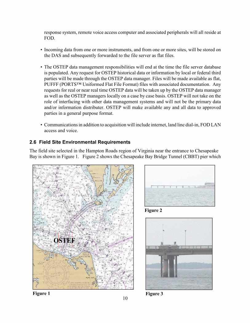
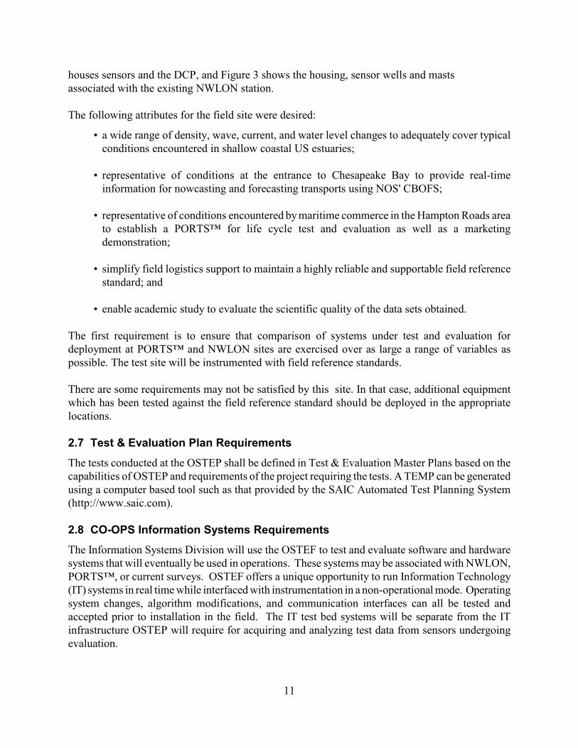
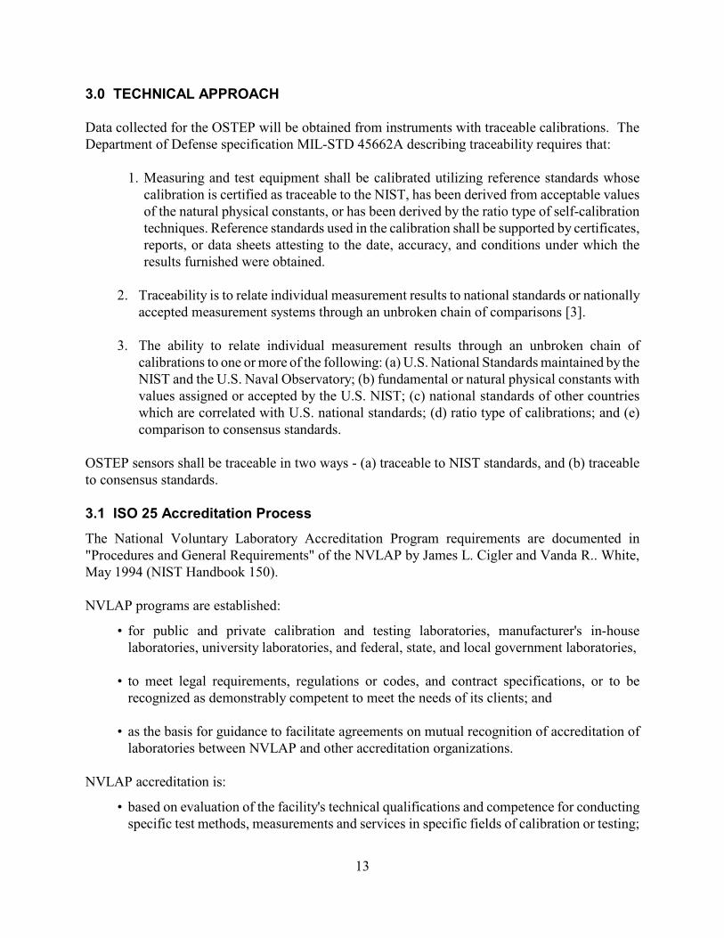
2.6 Field Site Environmental Requirements
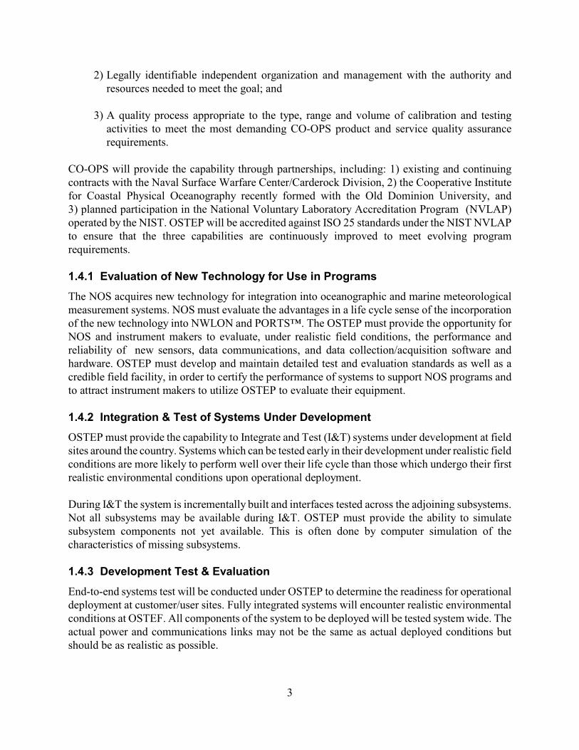
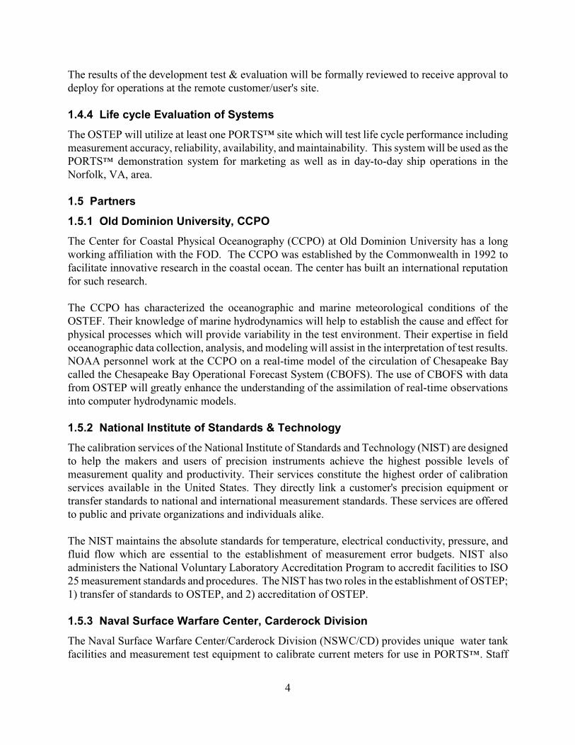
The field site selected in the Hampton Roads region of Virginia near the entrance to Chesapeake Bay is shown in Figure 1. Figure 2 shows the Chesapeake Bay Bridge Tunnel (CBBT) pier which
11
houses sensors and the DCP, and Figure 3 shows the housing, sensor wells and masts associated with the existing NWLON station.
The following attributes for the field site were desired:
• a wide range of density, wave, current, and water level changes to adequately cover typicalconditions encountered in shallow coastal US estuaries;
• representative of conditions at the entrance to Chesapeake Bay to provide real-timeinformation for nowcasting and forecasting transports using NOS' CBOFS;
• representative of conditions encountered by maritime commerce in the Hampton Roads areato establish a PORTS™ for life cycle test and evaluation as well as a marketingdemonstration;
• simplify field logistics support to maintain a highly reliable and supportable field referencestandard; and
• enable academic study to evaluate the scientific quality of the data sets obtained.
The first requirement is to ensure that comparison of systems under test and evaluation fordeployment at PORTS™ and NWLON sites are exercised over as large a range of variables aspossible. The test site will be instrumented with field reference standards.
There are some requirements may not be satisfied by this site. In that case, additional equipmentwhich has been tested against the field reference standard should be deployed in the appropriatelocations.
2.7 Test & Evaluation Plan Requirements
The tests conducted at the OSTEP shall be defined in Test & Evaluation Master Plans based on thecapabilities of OSTEP and requirements of the project requiring the tests. A TEMP can be generatedusing a computer based tool such as that provided by the SAIC Automated Test Planning System(http://www.saic.com).
2.8 CO-OPS Information Systems Requirements
The Information Systems Division will use the OSTEF to test and evaluate software and hardwaresystems that will eventually be used in operations. These systems may be associated with NWLON,PORTS™, or current surveys. OSTEF offers a unique opportunity to run Information Technology(IT) systems in real time while interfaced with instrumentation in a non-operational mode. Operatingsystem changes, algorithm modifications, and communication interfaces can all be tested andaccepted prior to installation in the field. The IT test bed systems will be separate from the ITinfrastructure OSTEP will require for acquiring and analyzing test data from sensors undergoingevaluation.

12
13
3.0 TECHNICAL APPROACH
Data collected for the OSTEP will be obtained from instruments with traceable calibrations. TheDepartment of Defense specification MIL-STD 45662A describing traceability requires that:
1. Measuring and test equipment shall be calibrated utilizing reference standards whosecalibration is certified as traceable to the NIST, has been derived from acceptable valuesof the natural physical constants, or has been derived by the ratio type of self-calibrationtechniques. Reference standards used in the calibration shall be supported by certificates,reports, or data sheets attesting to the date, accuracy, and conditions under which theresults furnished were obtained.
2. Traceability is to relate individual measurement results to national standards or nationallyaccepted measurement systems through an unbroken chain of comparisons [3].
3. The ability to relate individual measurement results through an unbroken chain ofcalibrations to one or more of the following: (a) U.S. National Standards maintained by theNIST and the U.S. Naval Observatory; (b) fundamental or natural physical constants withvalues assigned or accepted by the U.S. NIST; (c) national standards of other countrieswhich are correlated with U.S. national standards; (d) ratio type of calibrations; and (e)comparison to consensus standards.
OSTEP sensors shall be traceable in two ways - (a) traceable to NIST standards, and (b) traceableto consensus standards.
3.1 ISO 25 Accreditation Process
The National Voluntary Laboratory Accreditation Program requirements are documented in"Procedures and General Requirements" of the NVLAP by James L. Cigler and Vanda R.. White,May 1994 (NIST Handbook 150).
NVLAP programs are established:
• for public and private calibration and testing laboratories, manufacturer's in-houselaboratories, university laboratories, and federal, state, and local government laboratories,
• to meet legal requirements, regulations or codes, and contract specifications, or to berecognized as demonstrably competent to meet the needs of its clients; and
• as the basis for guidance to facilitate agreements on mutual recognition of accreditation oflaboratories between NVLAP and other accreditation organizations.
NVLAP accreditation is:
• based on evaluation of the facility's technical qualifications and competence for conductingspecific test methods, measurements and services in specific fields of calibration or testing;
14
• granted only after thorough evaluation that the applicant has demonstrated that all NVLAPcriteria have been met;
• acknowledged by the issuance of two documents to attest to that compliance: (1) a Certificateof Accreditation, and (2) a Scope of Accreditation which details the specific test methods,measurements and services for which a laboratory has been accredited.
A request to establish a Laboratory Accreditation Program (LAP) must be made to the Director ofNIST and include:
• the scope of the LAP in terms of products, calibration services, or testing services proposedfor inclusion;
• specific identification of the applicable standards and test methods, including appropriatedesignations, and the organizations or standards-writing bodies having responsibility forthem;
• a statement of the perceived need for the LAP;
• a statement of the extent to which the requester is willing to support necessary developmentalaspects of the LAP with funding and personnel.
3.2 Facility Organization & Staff Competencies
3.3 Test & Evaluation Process and Planing
The tests conducted at the OSTEP shall be defined in Test & Evaluation Master Plans based on thecapabilities of OSTEP and requirements of the project requiring the tests. A TEMP can be generatedusing a computer based tool such as that provided by the SAIC Automated Test Planning System(http://www.saic.com).
A typical Test & Evaluation Master Plan (TEMP) is outlined below with the prefix TEMP todistinguish between outline sections and OSTEP plan sections:
TEMP 1. IntroductionTEMP 1.1 Goals & ObjectivesTEMP 1.2 Risk AssessmentTEMP 1.3 Minimum Acceptable Operational Performance RequirementsTEMP 1.4 Systems Under T&E DescriptionTEMP 1.5 Critical Technical ParametersTEMP 2. Integrated Test Program SummaryTEMP 2.1 Master ScheduleTEMP 2.2 ManagementTEMP 3. Developmental Test and Evaluation (DT&E)TEMP 3.1 OverviewTEMP 3.2 Configuration Description
15
TEMP 3.3 DT&E ObjectivesTEMP 3.4 DT&E Events, Scope of Testing, and ScenariosTEMP 4. Operational Test and Evaluation (OT&E)TEMP 4. 1 OverviewTEMP 4.2 Critical Operational IssuesTEMP 4.3 Configuration DescriptionTEMP 4.4 OT&E Events, Scope of Testing, and ScenariosTEMP 4.5 Live Evaluation by UsersTEMP 5. T&E Resource SummaryTEMP 5.1 Test ArticlesTEMP 5.2 Test Sites & InstrumentationTEMP 5.3 Test Support EquipmentTEMP 5.4 RisksTEMP 5. External ContributorsTEMP 5.6 Operational Test SupportTEMP 5.7 Simulations, Models and TestbedsTEMP 5.8 Special RequirementsTEMP 5.9 T&E Funding RequirementsTEMP 5.10 Manpower/Personnel Training
TEMP Appendix A BibliographyTEMP Appendix B ACRONYMSTEMP Appendix C Points of ContactTEMP Attachments
3.4 Software Quality Assurance Process
All OSTEP data, analysis and results will pass through the software systems in place at the facility.To ensure these software subsystems adhere to applicable standards, procedures, and requirements,a software quality assurance process is required.
The Software Engineering Institute at Carnegie Mellon University, Pittsburg, Pennsylvania hasdeveloped a framework that describes the key elements of an effective software process. Amongother things, this framework addresses the software quality assurance process. This process, calledthe Capability Maturity Model for Software (CMM) provides a clearly defined, evolutionary anddisciplined path for software developers to follow. CMM is used throughout the industry and isrecognized as an accepted and proven model to adopt when defining the software process.
3.5 Total Quality Assurance Process
The DQA plan for a marine measurement program specifies the Total Quality Assurance Process forthe data collection and processing systems, personnel, and facilities are to be used to obtain the datato meet the program objectives. The plan includes an uncertainty statement about the data to becollected and details the procedures to be used to achieve the allowable error objective of themeasurement program. Procedures to be considered in developing the plan are related both to theplanning and operations portions of the measurement program.
16
3.5.1 General Considerations
The DQA plan should:
• Parallel the course of events in the measurement program. The measurement program planshould provide the sequence of events. For many programs, the DQA and measurementprogram plans can be merged into a single document.
• Serve as a management tool for control of the measurement program. Thus, the programmanagement must review the DQA plan.
• Identify existing organizational procedures appropriate for the program. (The use of existingprocedures decreases the need to commit unnecessary resources, and organizationalpersonnel involved in the DQA plan will most likely be familiar with them.)
17
Figure 4
Program Manager
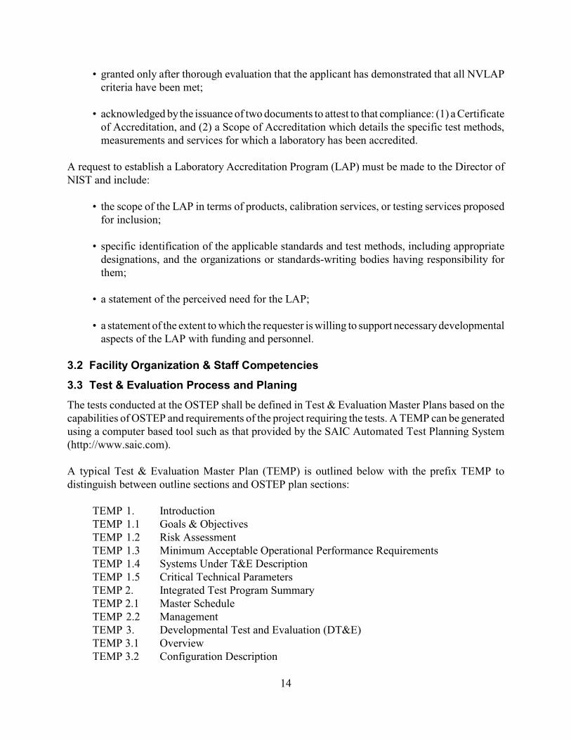
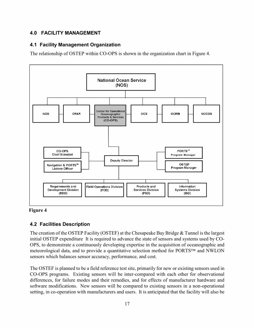
4.0 FACILITY MANAGEMENT
4.1 Facility Management Organization
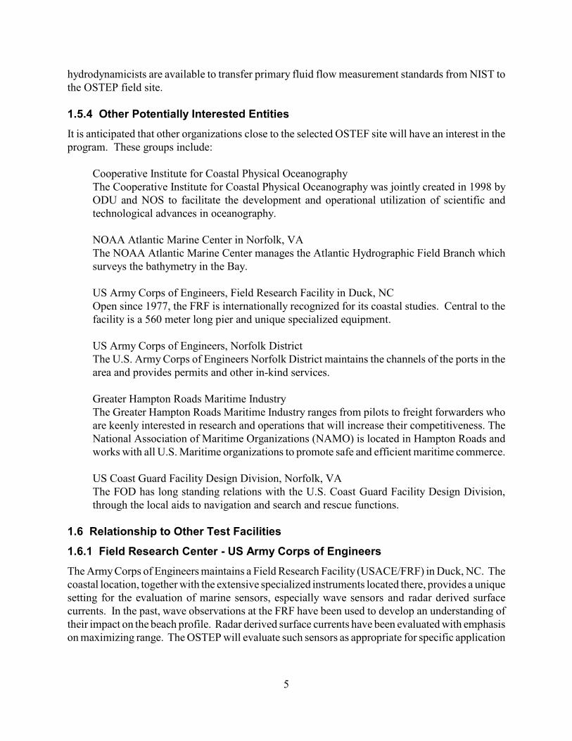
The relationship of OSTEP within CO-OPS is shown in the organization chart in Figure 4.
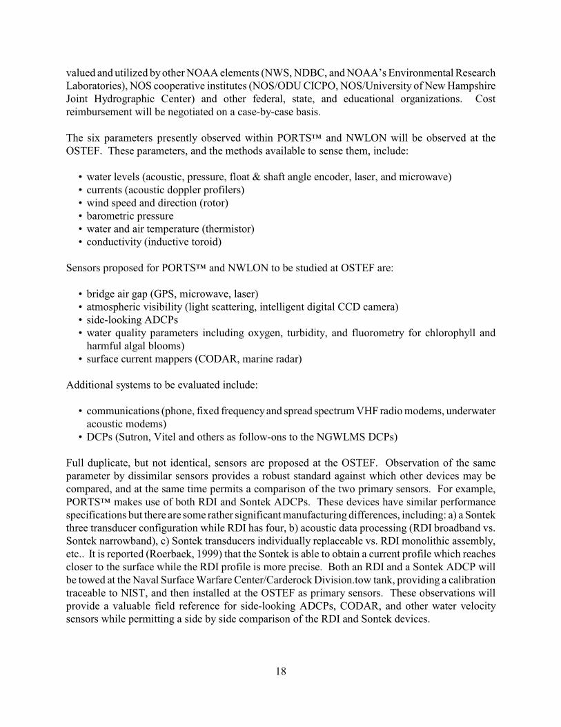
4.2 Facilities Description
The creation of the OSTEP Facility (OSTEF) at the Chesapeake Bay Bridge & Tunnel is the largestinitial OSTEP expenditure It is required to advance the state of sensors and systems used by CO-OPS, to demonstrate a continuously developing expertise in the acquisition of oceanographic andmeteorological data, and to provide a quantitative selection method for PORTS™ and NWLONsensors which balances sensor accuracy, performance, and cost.
The OSTEF is planned to be a field reference test site, primarily for new or existing sensors used inCO-OPS programs. Existing sensors will be inter-compared with each other for observationaldifferences, for failure modes and their remedies, and for effects of manufacturer hardware andsoftware modifications. New sensors will be compared to existing sensors in a non-operationalsetting, in co-operation with manufacturers and users. It is anticipated that the facility will also be
18
valued and utilized by other NOAA elements (NWS, NDBC, and NOAA’s Environmental ResearchLaboratories), NOS cooperative institutes (NOS/ODU CICPO, NOS/University of New HampshireJoint Hydrographic Center) and other federal, state, and educational organizations. Costreimbursement will be negotiated on a case-by-case basis.
The six parameters presently observed within PORTS™ and NWLON will be observed at theOSTEF. These parameters, and the methods available to sense them, include:
• water levels (acoustic, pressure, float & shaft angle encoder, laser, and microwave)• currents (acoustic doppler profilers)• wind speed and direction (rotor)• barometric pressure• water and air temperature (thermistor)• conductivity (inductive toroid)
Sensors proposed for PORTS™ and NWLON to be studied at OSTEF are:
• bridge air gap (GPS, microwave, laser)• atmospheric visibility (light scattering, intelligent digital CCD camera)• side-looking ADCPs• water quality parameters including oxygen, turbidity, and fluorometry for chlorophyll and
harmful algal blooms)• surface current mappers (CODAR, marine radar)
Additional systems to be evaluated include:
• communications (phone, fixed frequency and spread spectrum VHF radio modems, underwateracoustic modems)
• DCPs (Sutron, Vitel and others as follow-ons to the NGWLMS DCPs)
Full duplicate, but not identical, sensors are proposed at the OSTEF. Observation of the sameparameter by dissimilar sensors provides a robust standard against which other devices may becompared, and at the same time permits a comparison of the two primary sensors. For example,PORTS™ makes use of both RDI and Sontek ADCPs. These devices have similar performancespecifications but there are some rather significant manufacturing differences, including: a) a Sontekthree transducer configuration while RDI has four, b) acoustic data processing (RDI broadband vs.Sontek narrowband), c) Sontek transducers individually replaceable vs. RDI monolithic assembly,etc.. It is reported (Roerbaek, 1999) that the Sontek is able to obtain a current profile which reachescloser to the surface while the RDI profile is more precise. Both an RDI and a Sontek ADCP willbe towed at the Naval Surface Warfare Center/Carderock Division.tow tank, providing a calibrationtraceable to NIST, and then installed at the OSTEF as primary sensors. These observations willprovide a valuable field reference for side-looking ADCPs, CODAR, and other water velocitysensors while permitting a side by side comparison of the RDI and Sontek devices.
19
For budget and planning purposes, the OSTEF has been considered as simply another PORTS™
installation, and the budget template for PORTS™ FY 2001 has been used. Just as proposed fornew PORTS™, contractor support will be required at the OSTEF. CO-OPS/FOD in Chesapeakelacks the personnel resources to fully support the OSTEF (demonstrated by the $1M NWLONmaintenance backlog also proposed for FY 2001 funding). The $150K contractor cost applied to theother sites may appear high for this small “OSTEF PORTS™”. It is justified by the requirement formore frequent deployments and recoveries, the wider variety of instruments, and the need tomaintain a functional status required for external (paying) users. For these same reasons, therequirement for the purchase of a full suite of spare components is proposed for the OSTEF. It isanticipated that the contractor support will be commingled with the CO-OPS support. It is desirableto provide CO-OPS personnel the opportunity to work with the newest technology wheneverpossible, and to utilize the contractor support for the standard maintenance efforts.
Since OSTEF sensors will be replaced or re-configured more frequently than those in a standardPORTS™ installation, the use of OSTEF sensors for operational purposes must be approached withcaution. However, to enhance the benefits of CO-OPS’s OSTEP effort and to support the co-operative nature of the facility, it is vital that resultant data sets be readily available. It is proposedthat a separate and unique DAS be installed for OSTEF, and that OSTEF data be archived within theNational PORTS™ Database and accessible through the PORTS™ InfoHub, perhaps in a timedelayed mode. The proposed budget allows for these costs, which total almost 20% of the proposedOSTEF total. CORMS QC shall only be required for those sensors which will provide real-timedata.
4.3 Test Equipment
4.3.1 Field Oceanographic Reference Systems
The field oceanographic reference systems must be recognized at the finest available fieldoceanographic and marine meteorological systems for the measurement of temperature, conductivity,pressure, water velocity, water level (tidal and waves), wind velocity, air temperature, relativehumidity, and atmospheric pressure. It is recommended that vendors of systems be notified of NOS'intent to select reference systems of the highest accuracy and reliability and to calibrate them to anaccredited NIST standards transfer process. Vendors should be encouraged to compete for theselection of reference standard.
SeaBird Electronics supplies conductivity, temperature, and pressure (Parascientific) sensors of avery high quality. The choice of conductivity, temperature, and pressure sensors must meet theUNESCO standards for the determination of salinity and density of seawater using electricalconductivity.
Acoustic Doppler current profilers developed by RDI Inc and SonTek have been calibrated in thelaminar tow basin and used in PORTS™ applications. SonTek has to date provided the instrumentswith the lowest error especially near the surface in bottom mounted applications. SonTek suppliesAcoustic Doppler Velocimeters which can be accurately calibrated in the laboratory against LaserDoppler Velocimeters (Voulgaris, 1997).
20
The determination of water level requires reference sensors which can provide both long termaccuracy relative to a vertical Geodetic reference system as well as high sampling rate to determinedirectional wave characteristics. A trade study should be conducted with input from the AdvisoryPanel to select the proper water level reference system(s).
Marine meteorological measurements should be conducted using equipment calibrated by theNational Weather Service for the purpose.
4.4 Staff Position Descriptions
4.4.1 Technical Manager
The Technical manager must have an advanced degree in Physical Oceanography, Engineering FluidDynamics, or Physics with a strong emphasis on theoretical and experimental geophysical fluiddynamics.
4.4.2 Quality Assurance Manager
The Quality Assurance Manager must have a degree in Logistics Engineering, Systems Engineering,or Quality Assurance Engineering with training and experience in Total Quality Management.
4.4.3 Facility Operations Manager
The Facility Operations Manager must have a degree in Business Administration and experiencewith facility operations.
4.4.4 T&E Staff
The Test and Evaluation Staff should consist of an Electrical Engineer and a MechanicalEngineering with experience with ocean sensing and data acquisition systems.
4.4.5 IT Staff
OSTEP requires sufficient personnel to perform the following functions:
• Network Management• Database Management• System Administration• Software development and integration
It is assumed that any hardware support personnel would be acquired through a contract.
It is a requirement for the IRM staff to have the necessary education, training, technical knowledgeand experience to provide the necessary support for their assigned functions. In general, thefollowing minimum selection criteria will be used:
• College or University Trained - Bachelors Degree• A Computer Science or related major
21
• Sufficient experience to perform the functions - minimally 4-5 years of practical experience
Depending upon the selection pool, some functions could be combined. An on-going trainingprogram will be required and sufficient backups put in place.
4.5 Financial Management
The OSTEP shall be financially serviced through the Eastern Administrative Service Center inNorfolk, with oversight provided by CO-OPS management.
4.6 Advisory Board
The Advisory Board should be comprised of representatives from the following:
• Woods Hole Oceanographic Institution, MIT• Rosenstiel Institute of Oceanography, University of Miami• Department of Oceanography, University of Washington• Scripps Oceanographic Institution, University of California San Diego• NOAA's PMEL and AOML• NESDIS/National Oceanographic Data Center• Instrument Manufacturing Community Representatives• Software Engineering Institute, Carnegie Mellon University• Maritime Commerce representative(s)• Marine Resouce community representative(s)

22
23
5.0 REFERENCES
Garner, Ernest L., and S. D. Raspberry, “What’s new in Traceability”, Journal of Testing andEvaluation, JTEVA, Vol 21, No. 6 November 1993, pp. 505-509.
Cigler, James L., and V. R. White, “National Voluntary Laboratory Accreditation Program,Procedures and General Requirements”, NIST Handbook 150, 1994
Roerbaek, K., “Intercomparison between Acoustic Doppler Current Profilers”, Proceedings of theIEEE Sixth Working Conference on Current Measurement, March 11-13, 1999, pp. 198-203.
Voulgaris, G. and J. Trowbridge, WHOI, 1997. “Evaluation of the ADV for TurbulenceMeasurements” submitted to Journal of Atmospheric and Oceanic Technology.
“Guide to Meteorological Instruments and Observing Practices”, Fourth edition, WMO - No. 8TP. 3, 1971. Secretariat of the World Meteorological Organization, Geneva, Switzerland.

24

25
APPENDICES

26
27
Appendix I
Schedule
The schedule for the establishment of the OSTEP must be event based. The establishment of theOSTEP capabilities to underwrite legal liability is more important than meeting arbitrary milestones.The major constraints on the schedule for events are the following:
• Funding• Availability of Full Time Equivalents to hire personnel • Availability of Division management personnel • Availability of partner personnel
The schedule must be revised when a work breakdown structure for the Facility establishment iscompleted.
Year 1 - acquire local contractor services- acquire and install duplicate OSTEF sensors- implement OSTEF- begin acquisition of CO-OPS new sensors to be tested- begin pursuit of NIST certification
Year 2 - begin installation and testing of CO-OPS new sensors- begin OSTEP database development- obtain NIST certification- begin partner & gov agency new sensor test discussions
Year 3 - implement and populate new sensor database- accept partner & gov agency new sensor test- begin private sector sensor test discussions

28
29
Appendix II
New Sensors
A variety of new sensors are desired and/or poised for inclusion in the suite of PORTS™instruments. Plans for new programs such as Coastal GOOS call for additional sensed parameters,and both PORTS™ and NWLON are well positioned to serve as the “backbone” for these programs.With the ability to integrate new sensors quickly (either as approved PORTS™ devices or ancillaryobservations for distribution on the CO-OPS InfoHub), CO-OPS will maintain a leadership role inthese new programs.
Several commercially available sensors have made significant progress in transitioning from researchinstruments to operational devices. They are briefly described here.
Side-looking Doppler ProfilersA SonTek side-looking ADP has been installed and appears to be operating well at Shinnecock InletNY (for examples of the side-looking ADP data available in real time see the web sitehttp://www.LIShore.org/shinnecock/latest.htm.). Cost to procure and install a SonTek SL ADP isestimated at $40K. RDI has a two year $400K Phase 2 SBIR to develop a side-looking profiler, butalso offers a 600KHz device recently developed for a Japanese firm, available for approximately$30K.
Current Mapping Using RadarRadar devices for the observation of surface currents have the potential to greatly enhance the CO-OPS current analysis effort. Such instruments have applications in a PORTS™ and the routinemapping of tidal currents. They are also ideal for event-driven current mapping activites such ashazardous materials spills and search and recovery efforts. CODAR installations in Monterey Bay,Rutgers LEO-15, Texas, and San Francisco have demonstrated an operational status and impressivedata value from these devices.
NOAA’s ETL Remote Sensing Laboratory owns two CODAR systems and is tasked with technologytransfer to an operation environment. They have expressed interest in a cooperative demonstration.The cost to procure and install a CODAR system is estimated to be $250K, and CO-OPS receivedfunding in FY 2000 to procure and manage the operation of a system in the Gulf of Fonseca. TheNavy’s NRL plans to evaluate a HIFAR system built by MetraTek (http://www.metratek.net), andthey have expressed interest in partnering. They also have interest in further development of a finescale current mapping system using standard low-cost marine microwave radar units.
Of the three systems (CODAR, HIFAR, and standard low-cost marine microwave radar), CODARis the only commercially available unit. The CODAR system is compact, portable, and has theability to be quickly installed for “quick response” efforts.
Offshore Water Level Measurements Using GPSPrecise centimeter level offshore water level measurements related to a recoverable referenceframework (ellipsoid) can be obtained from a GPS system placed on a floating platform (buoy,
30
barge, boat, etc.). These GPS-derived water level time series are used to compute tidal datums andharmonic constituents to support hydrographic surveys, maintenance dredging projects, verificationof numerical models, calibration of satellite altimeters, and mapping sea surface variability.
Most of the hardware required for this test is in hand or has been identified. A radio modemcommunications system is needed, costing about $10K.
Underwater Acoustic Modems for ADCPsAcoustic modems for the underwater transfer of ADCP data can eliminate the cost and failuresassociated with cabling. A new modem developed by LinkQuest (http://www.link-quest.com) offerslow power consumption, low error rates and high data transfer rates. It has successfully beeninterfaced to off-the-shelf ADCPs. The cost to procure a pair of modems for testing is approximately$12.4K. The manufacturer offers demonstrations at little or no cost in the southern California area.
Benthos also offers a recently developed acoustic modem and has expressed a willingness toparticipate in trial deployments.
Bridge Air GapAir gap sensors are available off the shelf from Saab and Miros (a microwave sensor with waveobservation capability, see http://www.miros.no) . They have also recently been developed byLockheed (a laser sensor developed through a CRADA) and Technology Services Corporation (amicrowave sensor developed through a SBIR). The TSC sensor was developed in support of a Phase1 SBIR, which does not require prototype development so the device is not NOAA property. Oneor more of these devices should be evaluated for inclusion in PORTS™. The most comprehensivetest would involve the comparison of several sensors.
RDI ADCP Wave SensorRDI has recently released software which provides observations of wave period, amplitude anddirection from a standard ADCP. This results in a wave sensor that is probably more robust thanmost existing wave gauges (since the instrument doesn’t reside on the ocean’s surface) whileproviding current profiles. Existing and potential PORTS™ customers have requested waveobservations. Tests to examine this new software and compare the resulting data to existingaccepted wave sensor data should be conducted.
31
Appendix III
OSTEP Budget
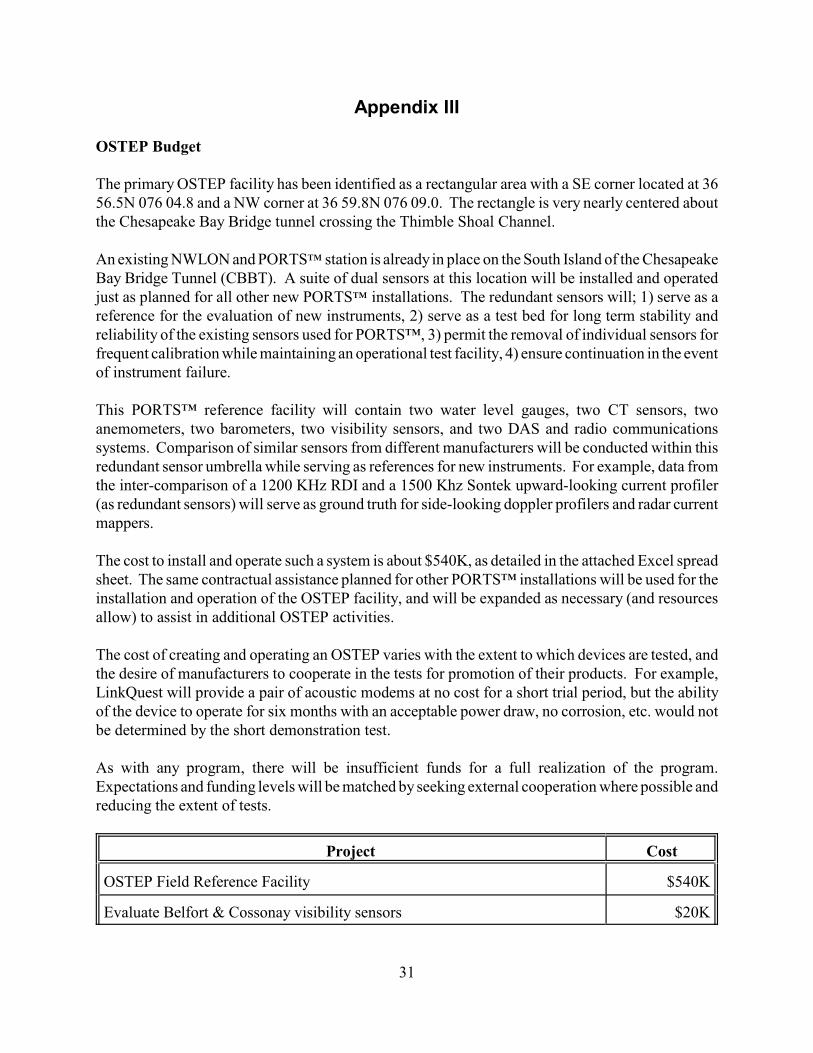
The primary OSTEP facility has been identified as a rectangular area with a SE corner located at 3656.5N 076 04.8 and a NW corner at 36 59.8N 076 09.0. The rectangle is very nearly centered aboutthe Chesapeake Bay Bridge tunnel crossing the Thimble Shoal Channel.
An existing NWLON and PORTS™ station is already in place on the South Island of the ChesapeakeBay Bridge Tunnel (CBBT). A suite of dual sensors at this location will be installed and operatedjust as planned for all other new PORTS™ installations. The redundant sensors will; 1) serve as areference for the evaluation of new instruments, 2) serve as a test bed for long term stability andreliability of the existing sensors used for PORTS™, 3) permit the removal of individual sensors forfrequent calibration while maintaining an operational test facility, 4) ensure continuation in the eventof instrument failure.
This PORTS™ reference facility will contain two water level gauges, two CT sensors, twoanemometers, two barometers, two visibility sensors, and two DAS and radio communicationssystems. Comparison of similar sensors from different manufacturers will be conducted within thisredundant sensor umbrella while serving as references for new instruments. For example, data fromthe inter-comparison of a 1200 KHz RDI and a 1500 Khz Sontek upward-looking current profiler(as redundant sensors) will serve as ground truth for side-looking doppler profilers and radar currentmappers.
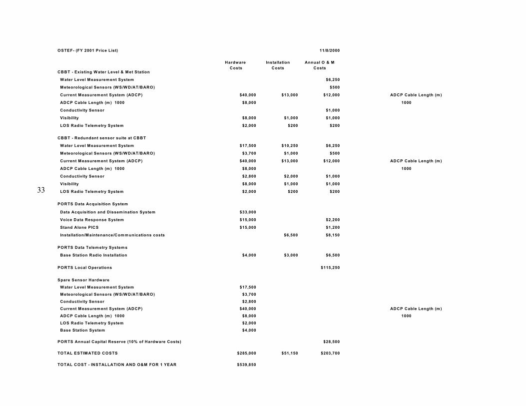
The cost to install and operate such a system is about $540K, as detailed in the attached Excel spreadsheet. The same contractual assistance planned for other PORTS™ installations will be used for theinstallation and operation of the OSTEP facility, and will be expanded as necessary (and resourcesallow) to assist in additional OSTEP activities.
The cost of creating and operating an OSTEP varies with the extent to which devices are tested, andthe desire of manufacturers to cooperate in the tests for promotion of their products. For example,LinkQuest will provide a pair of acoustic modems at no cost for a short trial period, but the abilityof the device to operate for six months with an acceptable power draw, no corrosion, etc. would notbe determined by the short demonstration test.
As with any program, there will be insufficient funds for a full realization of the program.Expectations and funding levels will be matched by seeking external cooperation where possible andreducing the extent of tests.
Project Cost
OSTEP Field Reference Facility $540K
Evaluate Belfort & Cossonay visibility sensors $20K
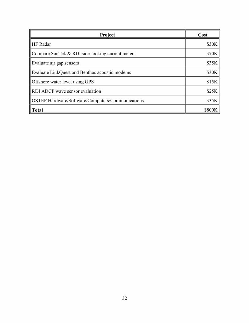
Project Cost
32
HF Radar $30K
Compare SonTek & RDI side-looking current meters $70K
Evaluate air gap sensors $35K
Evaluate LinkQuest and Benthos acoustic modems $30K
Offshore water level using GPS $15K
RDI ADCP wave sensor evaluation $25K
OSTEP Hardware/Software/Computers/Communications $35K
Total $800K
33
OSTEF- (FY 2001 Price List) 11/8/2000
Hardware
Costs
Installation
Costs
Annual O & M
CostsCBBT - Existing W ater Level & Met Station
W ater Level Measurem ent System $6,250
Meteorological Sensors (W S/W D/AT/BARO) $500
Current Measurem ent System (ADCP) $40,000 $13,000 $12,000 ADCP Cable Length (m )
ADCP Cable Length (m ) 1000 $8,000 1000
Conductivity Sensor $1,000
Visibility $8,000 $1,000 $1,000
LOS Radio Telem etry System $2,000 $200 $200
CBBT - Redundant sensor suite at CBBT
W ater Level Measurem ent System $17,500 $10,250 $6,250
Meteorological Sensors (W S/W D/AT/BARO) $3,700 $1,000 $500
Current Measurem ent System (ADCP) $40,000 $13,000 $12,000 ADCP Cable Length (m )
ADCP Cable Length (m ) 1000 $8,000 1000
Conductivity Sensor $2,800 $2,000 $1,000
Visibility $8,000 $1,000 $1,000
LOS Radio Telem etry System $2,000 $200 $200
PORTS Data Acquisition System
Data Acquisition and Dissem ination System $33,000
Voice Data Response System $15,000 $2,200
Stand Alone PICS $15,000 $1,200
Installation/M aintenance/Com m unications costs $6,500 $8,150
PORTS Data Telem etry System s
Base Station Radio Installation $4,000 $3,000 $6,500
PORTS Local Operations $115,250
Spare Sensor Hardware
W ater Level Measurem ent System $17,500
Meteorological Sensors (W S/W D/AT/BARO) $3,700
Conductivity Sensor $2,800
Current Measurem ent System (ADCP) $40,000 ADCP Cable Length (m )
ADCP Cable Length (m ) 1000 $8,000 1000
LOS Radio Telem etry System $2,000
Base Station System $4,000
PORTS Annual Capital Reserve (10% of Hardware Costs) $28,500
TOTAL ESTIM ATED COSTS $285,000 $51,150 $203,700
TOTAL COST - INSTALLATION AND O&M FOR 1 YEAR $539,850