Obtaining frequency responses of - ntcees.ru meeting Copenhagen... · Obtaining the frequency...
23
Obtaining the frequency responses of AVR and PSS using RTDS Simulator European User’s Group Meeting October 6–7, 2014 Technical University of Denmark Anton Kushnir, JSC «STC UPS»
-
Upload
nguyenkhuong -
Category
Documents
-
view
216 -
download
0
Transcript of Obtaining frequency responses of - ntcees.ru meeting Copenhagen... · Obtaining the frequency...

Obtaining the frequency responses of AVR and PSS using RTDS Simulator
European User’s Group Meeting
October 6–7, 2014 Technical University of Denmark
Anton Kushnir, JSC «STC UPS»
«STC UPS» JSC is a sub-company of System Operator. One of the directions of work which are performed in «STC UPS» JSC is testing AVRs and PSSs
Presently certification is performed on «STC UPS» JSC Physical Model
System Operator certificate
Since year 2002 «STC UPS» JSC are doing researches of AVR and PSS
Since year 2011 «STC UPS» JSC are performing certification tests

AVR type Manufacturer Country Date
Thyripol Siemens Germany 14.10.11
EX2100 General Electric USA 27.10.11
EAA Ansaldo Energia Italy 14.12.11
THYNE1 Andritz Hydro Austria 30.01.12
THYNE4/5/6 Andritz Hydro Austria 06.02.12
MEC600 Mitsubishi Japan 27.02.12
SEMIPOL Converteam Germany 01.06.12
DECS-2100 Basler Electric USA 19.11.12
Unitrol 6000/6800 ABB Switzerland 30.11.12
Unitrol 6080 ABB Switzerland 30.11.12
EX2100-BR General Electric USA 13.12.12
AVR-2 Energocomplect Russia 05.04.13
AVRs which received System Operator certificate

Researches of AVR and PSS performed in «STC UPS» JSC
AVR and PSS certification
Performing tests on Physical Model
Creating a verified mathematical
model
Adjusting AVR and PSS
coefficients
«Eurostag» calculations
Mathematical models of AVR and PSS are used for calculations
Creating model of Power System on Physical Model
Mathematical models of AVR and PSS are used within «Regulator» hardware-software system

PSS2B model structure

Usually for measuring frequency responses of SISO liner time-irrelevant system following methods are applied: 1. Sending on input of SISO system impulse and measuring
its response 2. Applying a signal with a wide frequency spectrum 3. Sending a constant-amplitude pure tone through the
bandwidth of interest and measuring the output level and phase shift relative to the input
Main problem – Limiters
MAX
MIN

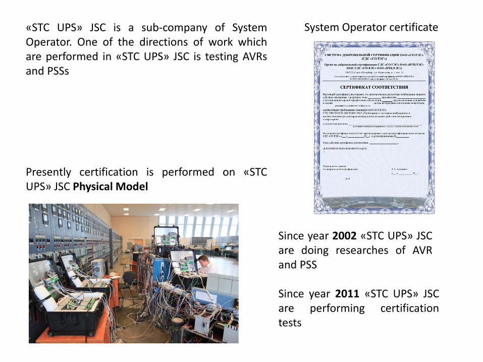
Other problems appear: 1. Input signals of AVR/PSS are instantaneous current and voltage 2. Most AVRs can't work without feedback signals 3. Some AVRs doesn't measure input parameters directly, instead of
that those parameters are calculated from other signals(i.e. field current is calculated from instantaneous currents, which are measured before rectifier)
4. PSS can’t work without AVR
Close-loop system
AVR+PSS
Power System
GTAIRTDS
Scale
Amplifier
uA
uB
uC i A i B i c I f Uf
If
SRC
w, rad/secU, kV
f, Hz
Signals send on
AVR/PSS
~iB
iC
GeneratorLine
Uf
iA
GTAO1 GTAO2
Thyristor Bridge
uA
uB
uC
GTDI
AVR+PSS
model
OR
PCFreqChar
DAC ADC
AVR+PSS
Scheme for obtaining the frequency responses of AVR/PSS full-scale specimens and AVR/PSS models

FreqChar software
Start
Frequency step, Hz
Bandwidth, Hz

FreqChar send modulation signal

SRC voltage

Terminal voltage, AVR output and field current
Assumption: AVR output = K*(Filtered field voltage)

W1(j)
W2(j)
in1
in2
outK1
K2
W1(j) W2(j)outin1
in2
K1 K2
Sometimes it is impossible to disable one or more inputs
1)
2)
Two cases:

W1(j)
in1
outK1 W2(j)K2
W2(j)K2in2
W1(j) W2(j)outin1
in2
K1 K2
Well known from control theory

2.0
-0.2
U+
-
UREF
If
K0U
1
0 .0 2 1p 0 .0 6 1
p
p
K1U
1
2 p
1
0 .0 2 1p 0 .1 5 1
p
p
K1IF
2
2 1
p
p
1
0 .0 2 1p K0FdF
1
0 .0 5 1p 0 .0 8 1
p
p K1F
∑
Uf
2.0
-1.5
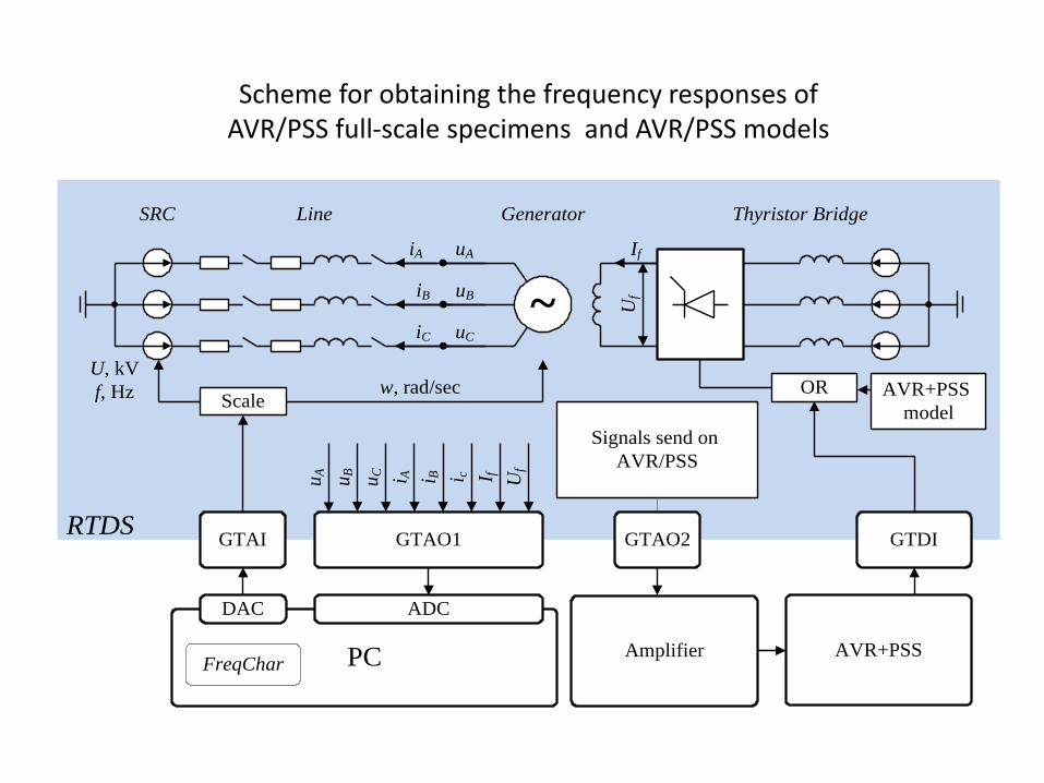
Method was approbated by obtaining the frequency responses of AVR and PSS mathematical models implemented in RTDS
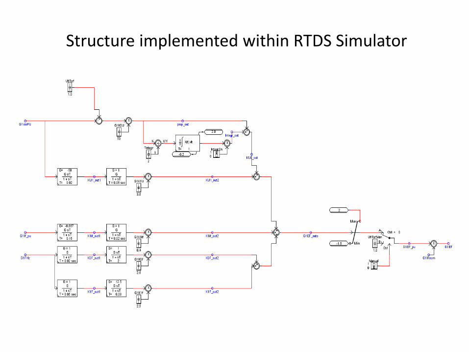
Structure implemented within RTDS Simulator

Frequency response of PI voltage regulator implemented within RTDS
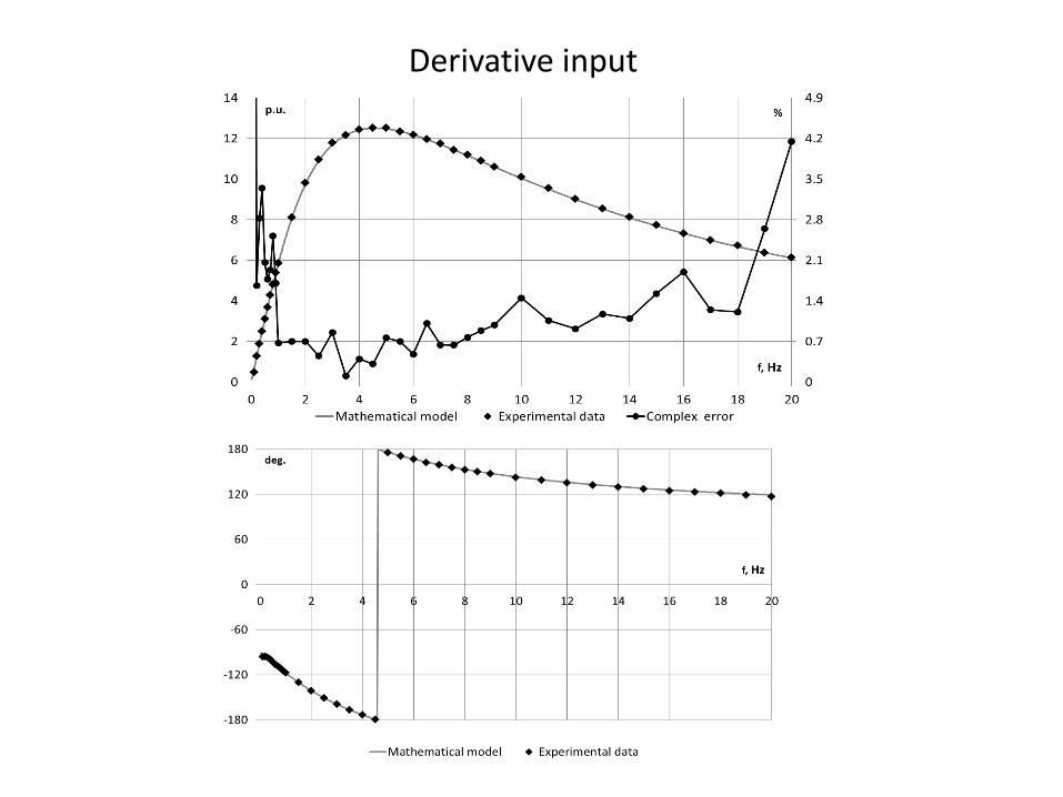
Derivative input

Frequency input

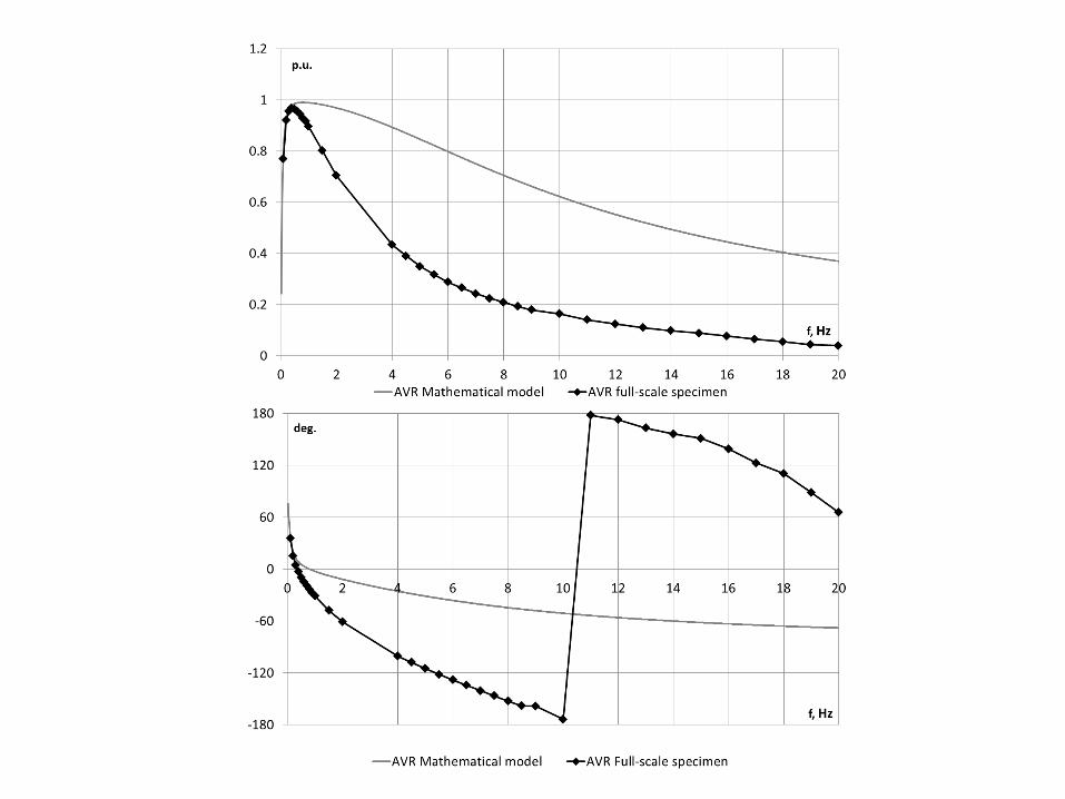
Some AVRs and PSSs have been already tested, and their frequency responses were obtained


Conclusion 1. Described method can be used for obtaining the frequency
responses of AVRs and PSSs 2. RTDS Simulator can be used for obtaining the frequency
responses of AVRs and PSSs and for verification of its mathematical models
3. Described method and RTDS Simulator can be used for creating more refined mathematical models.