OBSTACLE DETECTION WITH BLUETOOTH CONTROLLED VEHICLE...
17
OBSTACLE DETECTION WITH BLUETOOTH CONTROLLED VEHICLE MOTION BY Sasank Das Alladi Naga Aiswarya Vadlamani Priyadarsini Pethanaraj Rohit Chaitanya Kunkumagunta ECE 511 MICROPROCESSORS
Transcript of OBSTACLE DETECTION WITH BLUETOOTH CONTROLLED VEHICLE...

OBSTACLE DETECTION WITH BLUETOOTH
CONTROLLED VEHICLE MOTION
BYSasank Das Alladi
Naga Aiswarya Vadlamani
Priyadarsini Pethanaraj
Rohit Chaitanya Kunkumagunta
ECE 511 MICROPROCESSORS

MOTIVATION
• Hand gesture technology is an emerging innovation in recent times and has replaced the concept of a remote controller.
• Our aim is to build a vehicle, controlled through hand gestures with an integrated obstacle detection system.

OVERVIEW
• The accelerometer attached to the hand is responsible for the movement of vehicle and will stop if any object is detected, thus avoiding the crash, irrespective of the forward direction.• The end picture we intend to achieve will allow the user to control the
vehicle more flexibly, when compared to the remote control based system. • The obstacle detection system enables crash avoidance within the
range of 15 centimeters.

BLOCK DIAGRAM

• HARDWARE INTERFACING• It is done by connecting X-axis and Y-axis pins to the ports P1_3 and P1_4 (GPIO) of
the MSP. • The on-board Analog to Digital Converter (ADC) will convert an analog voltage on a
pin to a digital number. • The slave Bluetooth module is connected to its UART ports P1_1(Rx) and P1_2(Tx).
• SOFTWARE INTERFACING• The analogRead function converts the analog signal to digital format and the
experimental values are determined for each direction and characters were assigned. • The UART pins sends these characters to the Slave Bluetooth module using the
Serial.write function for transmission.
MSP430G2

ACCELEROMETER
• The accelerometer used is the ADXL335. • X and Y axis are interfaced to the MSP430G2 through the ports P1_3
and P1_4. • The X- axis is used for forward and backward motion whereas the Y-
axis is used for left and right motion.

ACCELEROMETER (Contd)• The table shown below has the experimental Values
for the movement of the car.
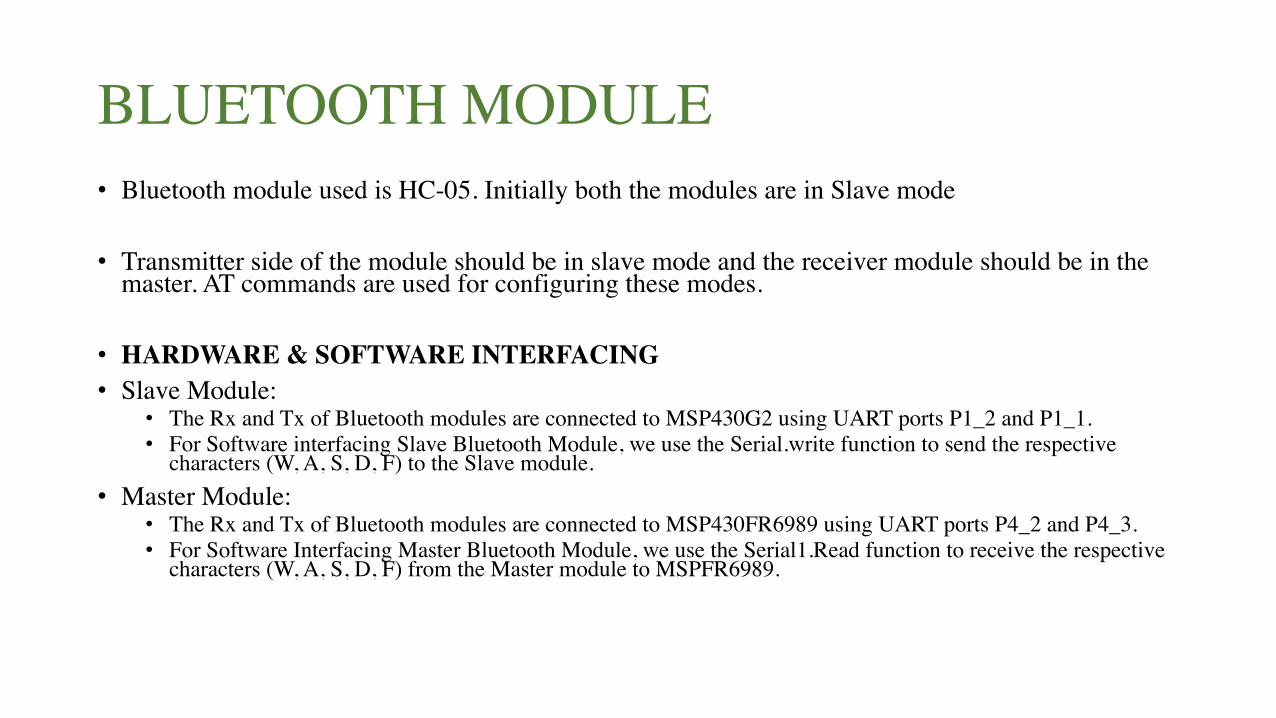
BLUETOOTH MODULE• Bluetooth module used is HC-05. Initially both the modules are in Slave mode
• Transmitter side of the module should be in slave mode and the receiver module should be in the master. AT commands are used for configuring these modes.
• HARDWARE & SOFTWARE INTERFACING• Slave Module:
• The Rx and Tx of Bluetooth modules are connected to MSP430G2 using UART ports P1_2 and P1_1. • For Software interfacing Slave Bluetooth Module, we use the Serial.write function to send the respective
characters (W, A, S, D, F) to the Slave module.• Master Module:
• The Rx and Tx of Bluetooth modules are connected to MSP430FR6989 using UART ports P4_2 and P4_3.• For Software Interfacing Master Bluetooth Module, we use the Serial1.Read function to receive the respective
characters (W, A, S, D, F) from the Master module to MSPFR6989.

REMOTE SIDE CONNECTION

MSP430FR6989
• The MSP used in the Vehicle side is MSP430FR6989
• The following ports of MSP is being used for vehicle side connection:• UART0 for LCD• UART1 for serial communication with the Master Bluetooth modules • LED1 and 2 for indicating directions. • GPIO pins for connecting the H-Bridge and Ultrasonic Sensor.

H-BRIDGE and DC MOTORS
• H-Bridge L293D drives the two D-C motors m1 and m2.
• The input pins of the H-Bridge are connected to the MSP and the Output pins are connected to the motors 1 and 2.
• Software interfacing • “pinMode” function to specify each pin as input/output for the MSP430 • “digitalWrite”, to set the pins to High/Low.

H-BRIDGE and DC MOTORS (Contd.)• Hardware Interfacing
• Supply and Ground pins from the MSP430 are used to power the H-Bridge. The enable pin connected to pin P2_3 of the MSP is kept high.
• For Motor1 signal: m1pin1 – P3_0, m1pin2 – P3_1,For Motor2 signal: m2pin1 – P2_4, m2pin2 – P4_7.For Motor1 drive: H-Bridge pin 3 and pin 6.For Motor2 drive: H-Bridge pin 11 and pin 14.

ULTRASONIC SENSOR
• The HC-SR04 is the sensor used.• For Hardware interfacing, the sensor’s trigger pin is connected to the pin P2_1 and the echo
pin is connected to the pin P2_2 of the MSP. • Following functions are used for Software interfacing
• “pinMode” to define if the pin is Input/output, here the Trigger pin is in output mode and Echo pin is in input mode.
• “digitalWrite” to write the trigger pin to high or low • “pulseIn” to read the reflected trigger signal off the object. • “delayMicroseconds” is used to time the trigger signal.
• The formula used to calculate distance is “microseconds / 29 / 2”.

VEHICLE SIDE CONNECTION

RESULTS
• The analog values were converted to digital format using MSP430 (ADC) and it was wirelessly transmitted through the Bluetooth module to the MSP430 on the vehicle side connection. • H-Bridge and DC motors were interfaced with the MSP430 to make
sure that the vehicle moves in the direction of the gesture made. • For crash avoidance, we have interfaced ultrasonic sensor to stop the
vehicle if the obstacle is within 15cm irrespective of the forward gesture given by the user.

DEMO

THANK YOU