Object-Oriented Design. From Analysis to Design Analysis Artifacts –Essential use cases What are...
24
Object-Oriented Design
-
Upload
ernest-hoover -
Category
Documents
-
view
222 -
download
1
Transcript of Object-Oriented Design. From Analysis to Design Analysis Artifacts –Essential use cases What are...
Object-Oriented Design

From Analysis to Design• Analysis Artifacts
– Essential use cases• What are the problem domain processes?
– Conceptual Model• What are the concepts and terms?
– System sequence diagrams• What are the system events and operations?
– Contracts• What do the system operations do?

Design Process1. Define real use cases including user interface and
reports.– Details may be left for implementation
2. Define interaction diagrams.
3. Refine design class diagrams.
4. Refine system architecture.
5. Define database schema.

Interaction Diagrams• Illustrate how objects interact via messages to
accomplish tasks.
• Show how responsibility for a task is distributed over a group of objects.
• Two kinds of UML interaction diagrams:– Sequence diagrams
– Collaboration diagrams
Responsibility Assignment• The amount of time spent on responsibility
assignment and generation of interaction diagrams should absorb a significant percentage of the overall project effort.
• This step requires more design skill than any other.
• Application of patterns, idioms, and principles can be applied to improve the quality of the design.

CRC Cards• Class-Responsibility-Collaborator Cards
• Not part of UML
• One index card for each class listing responsibilities and collaborators
• Developed in small groups where people role play various classes.
• Group design efforts with responsibility assignment and role playing are effective with or without CRC cards.
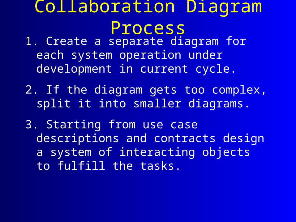
Collaboration Diagram Process1. Create a separate diagram for each system
operation under development in current cycle.
2. If the diagram gets too complex, split it into smaller diagrams.
3. Starting from use case descriptions and contracts design a system of interacting objects to fulfill the tasks.

Basic Notation
Sale s1:Sale:Sale
class instancenamed
instance
:Sale:POST1: addPayment(amount: Money)
link
message
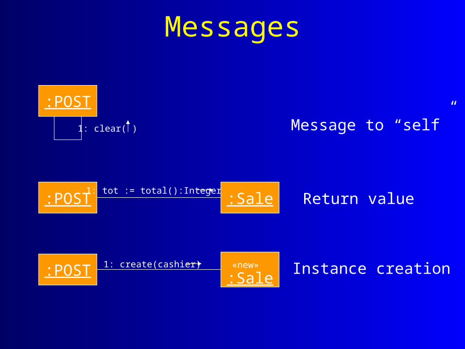
Messages
:POST
1: clear( ) Message to “self”
:POST1: tot := total():Integer
:Sale Return value
:POST 1: create(cashier) «new» :Sale
Instance creation
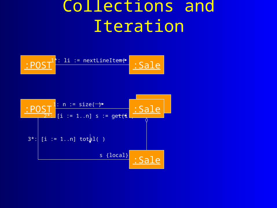
Collections and Iteration
:POST1*: li := nextLineItem( )
:Sale
:POST1: n := size( )
2*: [i := 1..n] s := get(i )
:Sale
3*: [i := 1..n] total( )
s {local}
:Sale

Message Sequence Numbering• The first message (usually corresponding to an
external event) is not numbered.
• Messages are numbered to indicate the order in which they are sent.– May be a simple numbering
– May use complex sequence numbering to show nesting of messages

Complex sequence numbering
:POST1: n := size( )
2*: [i := 1..n] s := get(i )
:Sale
3*: [i := 1..n] total( )
s {local}
:LineItem
3.l*: [for each] li := next( )
3.2*: [for each] subtotal( )
li {local}
totalSales( )
:LineItem
:Sale
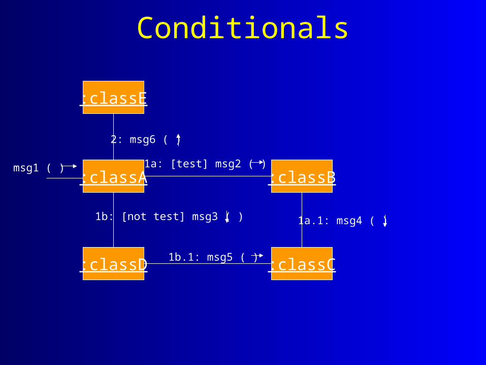
Conditionals
:classA :classB
:classC:classD
:classE
msg1 ( )
2: msg6 ( )
1a: [test] msg2 ( )
1b.1: msg5 ( )
1a.1: msg4 ( )1b: [not test] msg3 ( )

Messages to classes
:Sale1: d := today ( ): Date
Date
Refining Class Diagrams• Depends on:
– Existing design class diagram (in first development cycle, will be a copy of the conceptual class diagram).
– Interaction diagrams from which the software classes, methods, and associations that participate in the solution are identified.
• Developed in parallel with interaction diagrams.

Design class diagrams• Classes, associations, and attributes
• Interfaces with operations and constants
• Methods
• Attribute type information
• Navigability
• Dependencies
Refinement Process1. Analyze the interaction diagrams to identify
participating classes.
2. Add methods, attributes, and associations required to support the interactions.
3. Add type information to attributes and methods.
4. Add navigability arrows to show attribute visibility.
5. Add dependency relationship lines.

Methods• create messages may be omitted or mapped to
constructor methods in the implementation language.
• Accessor methods (get, set) may be omitted from diagrams.
• Messages to collections imply methods in the collection class itself (e.g. Vector, HashTable), not the class of objects in the collection.

Associations• Based on software-oriented need-to-know
criterion – what associations are required in order to support the interactions.
• Unlike conceptual model where associations may be justified by enhancement of problem domain comprehension.
• Like conceptual model, associations show relatively static structural relationships, not transient events.
Navigability• Arrows on associations indicate navigability from
the source to target class.
• Navigability from class A to B usually implies an attribute in A objects containing a reference to a B object.
• Design class diagrams should contain the appropriate navigability arrows.

Example: POS
POST
+endSale()+enterItem(ups: integer, qty: integer)+makePayment(amount: Money)
Sale
+becomeComplete()+total(): Money+makePayment(amount: Money)
date: Datetime: TimeisComplete: Boolean
1
*

Associations and Dependencies• Associations are static structural relationships that
are visible via attributes.
• A dependency relationship indicates that one class has non-attribute knowledge of another.
• Dependencies arise through parameters, local variables, and global variables.
• Dependencies are illustrated by dashed arrows on design class diagrams.

Key Points• Interaction diagrams show how responsibility for
a task is distributed over a group of objects.
• Compared to sequence diagrams, collaboration diagrams:– Offer exceptional expressiveness, ability to convey
contextual information and relative spatial economy.
– Also, more complexity.
Key Points (2)• Responsibility assignment requires significant
time and skill.
• Design class diagrams include more information than conceptual diagrams:– Methods, type information, navigability, dependencies
• Designs are based on software-oriented need-to-know criteria rather than problem domain criteria.