Object Detection with IO-Link WORLD-BEAM QS18E Clear
20
WORLD-BEAM ® QS18E Clear Object Detection with IO-Link Instruction Manual Original Instructions 196873 Rev. A 10 January 2017 © Banner Engineering Corp. All rights reserved 196873
Transcript of Object Detection with IO-Link WORLD-BEAM QS18E Clear
WORLD-BEAM® QS18E ClearObject Detection with IO-Link
Instruction Manual
Original Instructions196873 Rev. A10 January 2017© Banner Engineering Corp. All rights reserved
196873

Contents1 Product Description ....................................................................................................... 3
1.1 Models ....................................................................................................................................31.2 Overview ................................................................................................................................ 4
2 Installation .....................................................................................................................52.1 Installing and Mounting the Sensor for Low Contrast Applications ................................................... 52.2 Wiring Diagrams ...................................................................................................................... 5
3 Sensor Configuration ..................................................................................................... 73.1 Push Button Configuration ..........................................................................................................73.2 Remote Input Configuration .......................................................................................................7
4 Select Sensing Mode ...................................................................................................... 94.1 Transparent Mode Set ................................................................................................................94.2 Film Mode Set .........................................................................................................................104.3 Opaque Mode Set ...................................................................................................................11
5 IO-Link Interface ..........................................................................................................136 Specifications .............................................................................................................. 14
6.1 Dimensions ........................................................................................................................... 156.2 Performance Curves ............................................................................................................... 15
7 Accessories ...................................................................................................................167.1 Cordsets ............................................................................................................................... 167.2 Retroreflectors .......................................................................................................................167.3 Brackets ............................................................................................................................... 17
8 Contact Us ................................................................................................................... 199 Banner Engineering Corp. Limited Warranty ................................................................ 20
WORLD-BEAM® QS18E Clear Object Detection with IO-Link
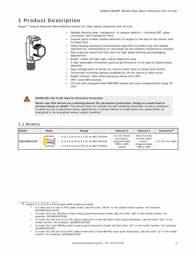
1 Product DescriptionExpert™ Coaxial Polarized Retroreflective Sensor for Clear Object Detection with IO-Link
• Reliably detects clear, transparent, or opaque objects — including PET, glasscontainers, and transparent films
• Coaxial optics enable reliable detection of targets to the face of the sensor withno dead zone
• ClearTracking automatic compensation algorithm provides long and reliableoperation by compensating for dust build up and ambient temperature changes
• Fast response speed with low jitter for high speed bottling and packagingapplications
• Bright, visible red light spot makes alignment easy• 3 user-selectable thresholds optimize performance to the type of object being
detected• Easy configuration of sensor by remote teach input or tactile push button• Convenient mounting options available for 18 mm barrel or side mount• Bright indicator LEDs show operating status from 360°• IP67 rated ABS housing• IO-Link with programmable PNP/NPN output and input configurations using IO-
Link
WARNING: Not To Be Used for Personnel Protection
Never use this device as a sensing device for personnel protection. Doing so could lead toserious injury or death. This device does not include the self-checking redundant circuitry necessaryto allow its use in personnel safety applications. A sensor failure or malfunction can cause either anenergized or de-energized sensor output condition.
1.1 ModelsModel Mode Range Channel 1 Channel 2 Connector1
QS18EK6XLPC
POLAR RETRO
CLEAR OBJECT 0 to 1.3 m (0 to 4.2 ft) on BRT-40X19A
0 to 2.0 m (0 to 6.5 ft) on BRT-60X40C
0 to 3.0 m (0 to 9.8 ft) on BRT-92X92C
IO-Link, Push/pull output,
programmablePNP or NPN
output
Multi-functionremote input/
output,programmable
PNP or NPN
2 m (6.5 ft) cable
1 Integral 2 m (6.5 ft) unterminated cable models are listed.• To order the 9 m (30 ft) PVC cable model, add the suffix "W/30" to the cabled model number. For example,
QS18EK6XLPC W/30.• To order the 4-pin M12/Euro-style integral quick disconnect model, add the suffix "Q8" to the model number. For
example, QS18EK6XLPCQ8.• To order the 150 mm (6 in) PVC cable model with a 4-pin M12/Euro-style quick disconnect, add the suffix "Q5" to the
model number. For example, QS18EK6XLPCQ5.• To order the 4-pin M8/Pico-style integral quick disconnect model, add the suffix "Q7" to the model number. For example,
QS18EK6XLPCQ7.• To order the 150 mm (6 in) PVC cable model with a 4-pin M8/Pico-style quick disconnect, add the suffix "Q" to the model
number. For example, QS18EK6XLPCQ.
WORLD-BEAM® QS18E Clear Object Detection with IO-Link
www.bannerengineering.com - Tel: 763.544.3164 3

1.2 Overview
Amber LED
(Output Indicator)Green LED
(Power Indicator) Push Button
The Banner QS18 sensor is a high performance clear object detectionsensor with an IO-link and multifunction output. The polarized coaxialoptical design ensures reliable detection of transparent, translucent, andopaque targets at any distance between the sensor and the reflector.Low contrast sensing applications include PET bottles, glass containers,and shrink wrap. The sensor can also be used to detect optical surfacessuch as: LCD panels with built in polarizing films, solar panels, andsemiconductor wafers.
Indicators (Two LEDs: One Green, One Amber)
Sensor Condition (Run Mode) Green LED Amber LED
Output OFF ON OFF
Output ON ON ON
Notification — Sensor needs to bereconfigured for reliable detection
Flashing at 5 Hz ON/OFF
Notification — Push button has been lockedout
Flashes 4 times andreturns to solid on
ON/OFF
WORLD-BEAM® QS18E Clear Object Detection with IO-Link
4 www.bannerengineering.com - Tel: 763.544.3164

2 Installation2.1 Installing and Mounting the Sensor for Low Contrast ApplicationsReliable transparent object detection depends on the sensor always detecting the object as "dark state" and the reflectoras the "light state". Using a recommended reflector, and proper orientation of the sensor to the reflector, is key to goodclear object detection. Optimize the reliable detection of transparent and clear objects by applying the following stepswhen mounting the sensor and selecting a retroreflective target.
1. If a bracket is needed, mount the sensor onto the bracket.2. Mount the sensor (or the sensor and the bracket) to the equipment at the desired location. Do not tighten at this
time.3. Align the sensor's light spot to the middle of the retroreflector.4. Mount the retroreflector perpendicular to the sensor optical axis (± 5°).5. Tighten the screws to secure the sensor (or the sensor and the bracket) to the aligned position.
2.1 Mounting Considerations for Opaque Objects with Mirror Like SurfacesTo minimize the potential for reflections from mirror like objects affecting the sensor, it is best to side mount the sensor.
2.2 Wiring Diagrams
IO-Link with PNP Output (Factory Default)
4
1
3
2
10-30V dcCH1
CH2
+
–PUSH
-PUL
L
Load
Load
Figure 1. Channel 1 = IO-Link, Channel 2 = PNPOutput
IO-Link with PNP Remote Input
4
1
3
2
10-30V dcCH1
CH2
+
–PUSH
-PUL
L
Load
RemoteInput
Figure 2. Channel 1 = IO-Link, Channel 2 = PNPRemote Input
Key
1. Brown2. White3. Blue4. Black
NOTE: NPN/PNP and Remote Input configurations are programmable using IO-Link.
NOTE: The remote input wire function needs to be enabled using IO-Link. The default for the remote input wirefunction is Detection Output.
NPN Discrete Outputs
4
1
3
2
10-30V dcCH1
CH2
+
–
Load
Load
Figure 3. Channel 1 = NPN Output, Channel 2 = NPNOutput
PNP Discrete Outputs
4
1
3
2
10-30V dcCH1
CH2
+
–
Load
Load
Figure 4. Channel 1 = PNP Output, Channel 2 = PNPOutput
WORLD-BEAM® QS18E Clear Object Detection with IO-Link
www.bannerengineering.com - Tel: 763.544.3164 5

NPN Output and Remote Input
4
1
3
2
10-30V dcCH1
CH2
+
–
Load
RemoteInput
Figure 5. Channel 1 = NPN Output, Channel 2 = NPNRemote Input
PNP Output and Remote Input
4
1
3
2
10-30V dcCH1
CH2
+
–
Load
RemoteInput
Figure 6. Channel 1 = PNP Output, Channel 2 = PNPRemote Input
WORLD-BEAM® QS18E Clear Object Detection with IO-Link
6 www.bannerengineering.com - Tel: 763.544.3164

3 Sensor ConfigurationSensor configuration can be performed using IO-Link, the push button, or the remote input wire once enabled through IO-link. Options include three sensing modes: Transparent, Film, and Opaque. Other configuration options include: outputdelay timing, health output, offset percentages, and the ClearTracking auto compensation algorithm. For more detail, seethe IO-Link IODD package (p/n 198215), which includes an IO-Link Data Map, on the Banner Website at http://www.bannerengineering.com.
3.1 Push Button ConfigurationUse the push button to configure the sensor. Click the push button according to Push Button Input Flowchart. After aconfiguration has been selected the sensor flashes both the green and amber LED to show which configuration wasselected followed by a rapid flashing of both the green and amber LED in unison to show acknowledgement and acceptanceof the configuration.
Unlock push buttons (flashing Green and Amber 1X followed by acceptance flash) defaultLock push buttons (flashing Green and Amber 2X followed by acceptance flash)Enable Auto compensation (flashing Green and Amber 3X followed by acceptance flash)Disable Auto compensation (flashing Green and Amber 4X followed by acceptance flash) defaultEnable 30 ms Off Delay (flashing Green and Amber 5X followed by acceptance flash)Disable 30 ms Off Delay (flashing Green and Amber 6X followed by acceptance flash) default
Click 2X Basic Configuration (alternating flashing Green and Amber LEDs at 1Hz)
Advanced Configuration (simultaneous flashing both Green and Amber LEDs at 1Hz)
Press and hold push button > 2 sec.
Hold is > 2 sec. and < 4 sec.Click is > 40 ms and < 800 ms
User Interface Push Button
(configuration using user interface push button)
Note: Initiate Sensor Mode Selection is required before the selected Mode takes effect.
Initiate Translucent, Film or Opaque Selection
Click 2XClick 1X Set output to Light Operate (flashing Green and Amber 1X followed by acceptance flash)
Set output to Dark Operate (flashing Green and Amber 2X followed by acceptance flash) default
Click 4XClick 3X Set offset to 8% offest (flashing Green and Amber 3X followed by acceptance flash)
Set offset to 16% offest (flashing Green and Amber 4X followed by acceptance flash) default
Sensor Push
Button
Click 5X Set offset to 32% offest (flashing Green and Amber 5X followed by acceptance flash)
Click 3x
Click 2XClick 1X
Click 4XClick 3X
Click 5XClick 6X
Select Translucent Mode defaultSelect Film ModeSelect Opaque Mode
Select Sensor Mode (flashing Amber LED at 1Hz)Click 5x
Click 2XClick 1X
Click 3X
Figure 7. Push Button Input Flowchart
3.2 Remote Input ConfigurationEnabling the remote input wire is done using IO-Link. Use the remote input function to configure the sensor remotely.Connect the white wire of the sensor as shown in the wiring diagram. Pulse the remote line according to the Remote InputFlowchart. After a configuration has been selected, both the green and amber LEDs will flash to show which configurationwas selected, followed by a rapid flashing of both the green and amber LED in unison to show acknowledgement andacceptance of the configuration.
WORLD-BEAM® QS18E Clear Object Detection with IO-Link
www.bannerengineering.com - Tel: 763.544.3164 7

2x1x Unlock push buttons (flashing Green and Amber 1X followed by acceptance flash) default
Lock push buttons (flashing Green and Amber 2X followed by acceptance flash)
4x3x Enable Auto compensation (flashing Green and Amber 3X followed by acceptance flash)
Disable Auto compensation (flashing Green and Amber 4X followed by acceptance flash) default5x Enable 30 ms Off Delay (flashing Green and Amber 5X followed by acceptance flash)6x Disable 30 ms Off Delay (flashing Green and Amber 6X followed by acceptance flash) default
1x
2x Basic Configuration (alternating flashing Green and Amber LEDs at 1Hz)
Advanced Configuration (simultaneous flashing both Green and Amber LEDs at 1Hz)
Initiate Transparent, Film or Opaque Selection
40 ms < T < 800 msTiming between Pulse groups > 1 second
Pulse Timing (T)
(gray wire is input wire)
2x1x Set output to Light Operate (flashing Green and Amber 1X followed by acceptance flash)
Set output to Dark Operate (flashing Green and Amber 2X followed by acceptance flash) default
4x3x Set offset to 8% offset (flashing Green and Amber 3X followed by acceptance flash)
Set offset to 16% offset (flashing Green and Amber 4X followed by acceptance flash) default
3x
Toggle Teach Button Lock/Unlock (flashing both Green and Amber LEDs 4X followed by acceptance flash)4x
Reset to Factory Defaults (flashing both Green and Amber LEDs 8X followed by acceptance flash)8x
Remote Input Wire
5x Set offset to 32% offset (flashing Green and Amber 5X followed by acceptance flash)
Select Translucent Mode defaultSelect Film ModeSelect Opaque Mode
Select Sensor Mode (flashing Amber LED at 1Hz)5x
2x1x
3x
Note: Initiate Sensor Mode Selection is required before the selected Mode takes effect.
Configuration using remote input wire when enabled through IO-Link
Figure 8. Remote Input Flowchart
WORLD-BEAM® QS18E Clear Object Detection with IO-Link
8 www.bannerengineering.com - Tel: 763.544.3164

4 Select Sensing ModeBy default, the sensing mode is set to Transparent. To select either Film or Opaque mode, follow these steps.
1. Access the Select Sensing Mode.
Method Action Result
Push Button Click the button 5-times.Select Sensing Modeenabled (Amber LEDflashes at 1 Hz).
Remote Line Pulse the remote line 5-times.T T
T
T
T
T
T
T
T
2. Select the desired sensing mode.
Method SensingMode Action Result
Push Button
Transparent Click the button 1-time.
The selectedsensing mode isenabled.
Film Click the button 2-times.
Opaque Click the button 3-times.
IO-Link
Transparent Set BDC1 Mode using IO-Link.
Film Set BDC1 Mode using IO-Link.
Opaque Set BDC1 Mode using IO-Link.
Remote Line
Transparent Pulse the remote line 1-time.T
Film Pulse the remote line 2-times.T T
T
Opaque Pulse the remote line 3-times.T T
T
T
T
4.1 Transparent Mode Set
Use Transparent mode for low contrast applications where the objectis not present during the teach process. Transparent mode is thedefault sensing mode and is best for most clear object detectionapplications.
Example Applications For Offset Percentages
8% Recommended for very low contrast applications with stableenvironmental conditions.
16% Recommended for most clear object detection applications intypical machine industrial environments.
32%Recommended for high contrast detections such as brown orgreen bottles, or opaque objects. This setting toleratesenvironmental challenges such as vibrations and dust build-up.
Darkest Most Light
Output ON Output OFF
Condition presented
Sensor position’s threshold is a programmable % offset below the presented condition
Figure 9. Transparent Mode
WORLD-BEAM® QS18E Clear Object Detection with IO-Link
www.bannerengineering.com - Tel: 763.544.3164 9

1. Prepare the sensor.
Method Action Result
Push Button,IO-Link, andRemote Line
Clear the light path to the reflector.
2. Access Transparent mode and set the sensing condition.
Method Action Result
Push ButtonPress and hold thebutton 2 to 4seconds.
Transparent Mode Configuration Accepted
Green LED Indicator: Flashes 3 times.
Green and Amber LED Indicators: Acceptance Flash—both LEDs flash 5 times rapidly in unison.
The sensor returns to Run mode with Transparent mode asthe sensing condition.
Transparent Mode Configuration Not Accepted
If there is not enough return signal the sensor will performan Opaque mode configuration indicated by:
Green and Amber LED Indicators: Flash 2 times.
Green and Amber LED Indicators: Acceptance Flash—both LEDs flash 5 times rapidly in unison and the GreenLED will continue to flash.
The sensor is not ready for transparent detection due toinsufficient light from the reflector, but is ready formaximum range Opaque object detection. Re-optimizealignment, check the reflector size for required range, andre-configure the sensor for transparent object detection.
IO-LinkSend Single ValueTeach commandusing IO-Link.
Remote Line Pulse the remoteline 1-time.
T
4.2 Film Mode Set
Film mode is useful when the transparent target cannot be removedfrom the light path during the teach procedure. This is common oncontinuous web processes such as shrink wrapping machinery. Thesensor learns the dark state with the web present and switches theoutput if the web breaks or runs out.
Example Applications For Offset Percentages
8% Recommended for very low contrast applications with stableenvironmental conditions.
16% Recommended for most clear object detection applications intypical machine industrial environments.
32%Recommended for high contrast detections such as brown orgreen bottles, or opaque objects. This setting toleratesenvironmental challenges such as vibrations and dust build-up.
Sensor positionsthreshold a programmable
% offset above the presented condition
Darkest(no signal)
Most Light(saturated
signal)
Output OFF Output ON
Condition Presented
Figure 10. Film Mode
1. Prepare the sensor.
WORLD-BEAM® QS18E Clear Object Detection with IO-Link
10 www.bannerengineering.com - Tel: 763.544.3164

Method Action Result
Push Button,IO-Link, andRemote Line
Align the light path to the reflector through a plastic film.
2. Access Film mode and set the sensing condition.
Method Action Result
Push Button Press and hold thebutton 2 to 4 seconds.
Film Mode Configuration Accepted
Green LED Indicator: Flashes 3 times.
Green and Amber LED Indicators: AcceptanceFlash - both LEDs flash 5 times rapidly in unison.
The sensor returns to Run mode with Film mode asthe sensing condition.
Film Mode Configuration Not Accepted
If there is not enough return signal the sensor willperform an Opaque mode configuration indicated by:
Green and Amber LED Indicators: Flash 2 times.
Green and Amber LED Indicators: AcceptanceFlash - both LEDs flash 5 times rapidly in unison andthe Green LED will continue to flash.
The sensor is not ready for film detection due toinsufficient light from the reflector, but is ready formaximum range Opaque object detection. Re-optimize alignment, check the reflector size forrequired range, and re-configure the sensor for filmdetection.
IO-LinkSend Single ValueTeach command usingIO-Link.
Remote Line Pulse the remote line1-time.
T
4.3 Opaque Mode Set
Opaque mode is recommended for long range detection of opaque(light blocking) targets. When Opaque mode is used, the sensoroperates at maximum sensing range regardless of the taughtcondition.
NOTE: The sensor's light spot is made brighter for60 seconds to assist in aligning the sensor to thereflector. This is particularly useful for long rangeapplications.
Darkest(no signal)
Most Light(saturatedsignal)
Output ON Output OFF
Fixed Threshold
Figure 11. Opaque Mode
1. Prepare the sensor.
Method Action Result
Push Button,IO-Link, andRemote Line
Present either the clear light path or blocked light path. Both areacceptable.
2. Access Opaque mode and set the sensing condition.
WORLD-BEAM® QS18E Clear Object Detection with IO-Link
www.bannerengineering.com - Tel: 763.544.3164 11

Method Action Result
Push Button Press and hold the button 2to 4 seconds.
Opaque Mode Configuration Accepted
Green LED Indicator: Flashes 3 times.
Green and Amber LED Indicators:Acceptance Flash - both LEDs flash 5 timesrapidly in unison, and the Green LED is on solid.
The sensor returns to Run mode with highexcess gain settings.
IO-Link Send Single Value Teachcommand using IO-Link.
Remote Line Pulse the remote line 1-time.T
WORLD-BEAM® QS18E Clear Object Detection with IO-Link
12 www.bannerengineering.com - Tel: 763.544.3164

5 IO-Link InterfaceIO-Link is a point-to-point communication link between a master device and sensor. It can be used to automaticallyparameterize sensors and transmit process data. For the latest IO-Link protocol and specifications, please visit the website at http://www.io-link.com.
The IO-Link IODD package (P/N 198215) is contained on the Banner Website at http://www.bannerengineering.com.
WORLD-BEAM® QS18E Clear Object Detection with IO-Link
www.bannerengineering.com - Tel: 763.544.3164 13

6 SpecificationsSupply Voltage and Current
10 V dc to 30 V dc (10% max. ripple) at 30 mA
Repeatability100 µs
Supply Protection CircuitryProtected against reverse polarity and transient overvoltages
Output Protection CircuitryProtected against false pulse on power-up and continuous overload orshort-circuit of output
Output ConfigurationChannel 1: IO-Link, Push/pull output, configurable PNP or NPN outputChannel 2: Multi-function remote input/output, configurable PNP orNPN
Output Response TimeMomentary delay on power-up, < 0.5 s, output does not conductduring this period400 µs ON/OFF
IO-Link InterfaceSupports Smart Sensor Profile: YesBaud Rate: 38400 bpsProcess Data Widths: 16 bitsIODD Files: Provides all programming options of button and remoteinput wire, plus additional functionality. Please see the IO-LinkDatamap document for more details.
Emitter LEDVisible red, 625 nm
IndicatorsTwo LEDs (1 green, 1 amber)Green solid: Indicates power applied and sensor readyGreen flashing: Indicates sensor operating in marginal state, in needof reconfigurationAmber solid: Indicates output conducting
Factory Default Settings
Setting Factory Default
Sensing Mode Transparent Mode
Output Logic Dark Operate
Offset Percent 16%
Push Button Unlocked
Auto Compensation Disabled
OFF Delay Disabled
Pin 4 Output IO-Link Enabled Detection Output (Push-pull)
Pin 2 Output Detection Output: High speed output whenusing IO-Link on Pin 4 (PNP)
Required Overcurrent Protection
WARNING: Electrical connections must be madeby qualified personnel in accordance with localand national electrical codes and regulations.
Overcurrent protection is required to be provided by end productapplication per the supplied table.Overcurrent protection may be provided with external fusing or viaCurrent Limiting, Class 2 Power Supply.Supply wiring leads < 24 AWG shall not be spliced.For additional product support, go to www.bannerengineering.com.
Supply Wiring (AWG) Required Overcurrent Protection (Amps)
20 5.0
22 3.0
24 2.0
26 1.0
28 0.8
30 0.5
ConstructionABS housing, PMMA window
Mounting TorqueNose mount: 18 mm mounting nut, 20 Ibf·in (2.3 N·m)Side mount: Two M3 screws, 5 Ibf·in (0.6 N·m)
ConnectionsPVC-jacketed 4-conductor 2 m (6.5 ft) or 9 m (30 ft) unterminatedcable, or 4-pin Euro-style or 4-pin Pico-style quick-disconnect (QD),either integral or 150 mm (6 in) pigtail, are available. QD cordsets areordered separately.
Operating Conditions−40 °C to +70 °C (−40 °F to +158 °F)95% at +50 °C maximum relative humidity (non-condensing)
Environmental RatingIEC IP67
Application NotesIf the push button does not appear to be responsive, perform the pushbutton enable procedure
Certifications
WORLD-BEAM® QS18E Clear Object Detection with IO-Link
14 www.bannerengineering.com - Tel: 763.544.3164

6.1 Dimensions
Pico Models Cable Models
Euro QD Models
6.2 Performance Curves
Spot Size vs. Distance
DISTANCE FROM SENSOR (mm)
BEAM
SIZE
(mm)
0
100
75
50
25
0 500 1000 1500 2000 2500 3000
Excess Gain
1
10
100
1.0 mm0.04"
10.0 mm0.4"
100 mm4.0"
1000 mm40.0"
10000 mm400"
DISTANCE FROM SENSOR (mm)
EXCE
SS G
AIN
BRT-92X92CBRT-84X84ABRT-51X51BMBRT-60X40CBRT-2X2LVCBRT-60X40C-PSBRT-32X20AMBRT-40X19ABRT-60X40 IP69KBRT-THG-3X3
WORLD-BEAM® QS18E Clear Object Detection with IO-Link
www.bannerengineering.com - Tel: 763.544.3164 15

7 Accessories7.1 Cordsets
4-Pin Threaded M12/Euro-Style Cordsets
Model Length Style Dimensions Pinout (Female)
MQDC-406 1.83 m (6 ft)
Straight
44 Typ.
ø 14.5M12 x 1
2
34
1
1 = Brown2 = White3 = Blue4 = Black
MQDC-415 4.57 m (15 ft)
MQDC-430 9.14 m (30 ft)
MQDC-450 15.2 m (50 ft)
MQDC-406RA 1.83 m (6 ft)
Right-Angle
32 Typ.[1.26"]
30 Typ.[1.18"]
ø 14.5 [0.57"]M12 x 1
MQDC-415RA 4.57 m (15 ft)
MQDC-430RA 9.14 m (30 ft)
MQDC-450RA 15.2 m (50 ft)
4-Pin Threaded M8/Pico-Style Cordsets
Model Length Style Dimensions Pinout (Female)
PKG4M-2 2 m (6.56 ft)
Straight ø 9.5
35 Typ.
M8 x 1
43 1
2
1 = Brown2 = White3 = Blue4 = Black
PKG4M-5 5 m (16.4 ft)
PKG4M-9 9 m (29.5 ft)
PKW4M-2 2 m (6.56 ft)
Right Angle
ø 9.5
28 Typ.
20 Typ.
M8 x 1
PKW4M-5 5 m (16.4 ft)
PKW4M-9 9 m (29.5 ft)
7.2 Retroreflectors
BRT-51X51BM
• Square, acrylic target• Reflectivity Factor: 1.5• Temperature: −20 °C to
+50 °C (−4 °F to+122 °F)
• Micro-prism geometry• Optional brackets are
available• Approximate size: 51
mm × 51 mm
BRT-60X40C• Rectangular, acrylic target• Reflectivity Factor: 1.4• Temperature: −20 °C to +60 °C
(−4 °F to +140 °F)• Optional brackets are available• Approximate size: 40 mm × 60
mm
WORLD-BEAM® QS18E Clear Object Detection with IO-Link
16 www.bannerengineering.com - Tel: 763.544.3164

BRT-92X92C
• Square, acrylic target• Reflectivity Factor: 3.0• Temperature: −20 °C to
+60 °C (−4 °F to+140 °F)
• Optional brackets areavailable
• Approximate size: 92mm × 92 mm
BRT-40X19A• Rectangular, acrylic target• Reflectivity Factor: 1.3• Temperature: −20 °C to +60 °C
(−4 °F to +140 °F)• Approximate size: 19 mm × 60 mm
overall; 19 mm × 40 mm reflector
BRT-60X40IP69K• Rectangular, acrylic target (color is
amber)• Reflectivity Factor: 0.7• Temperature: –20 °C to +140 °C
(–4 °F to +284 °F)• Chemically resistant• IP69K washdown rated• Optional brackets are available• Approximate size: 40 mm × 60
mm
BRT-60X40C-PS• Rectangular, polystyrene target• Reflectivity Factor: 1.1• Temperature: −20 °C to +60 °C
(−4 °F to +140 °F)• Optional brackets are available• Chemically compatible with
hydrogen peroxide• Yellow back• Approximate size: 40 mm × 60
mm
2 in retroreflective tape, 2.5 m (100 in)
Model Reflectivity Factor Maximum Temperature Size
BRT-THG-2-100 0.7 +60 °C (+140 °F) 50 mm (2 in) wide, 2.5 m (100 in) long
7.3 Brackets
SMB18A• Right-angle mounting
bracket with a curvedslot for versatileorientation
• 12-ga. stainless steel• 18 mm sensor mounting
hole• Clearance for M4 (#8)
hardware
30
41
46
A BC
Hole center spacing: A to B = 24.2Hole size: A = ø 4.6, B = 17.0 × 4.6, C = ø 18.5
SMBQS18Y• Die-cast bracket for 18
mm holes• Includes metal hex nut
and lock washer• Allows ± 8° for cabled
sensors
Hole size: A = ø 15.3
7.8 mm[0.31"]
15.5 mm[0.61"]
19.5 mm[0.77"]
9.8 mm[0.38"]
14.5 mm[0.57"]
25.4 mm[1"]
16.4 mm[0.65"]
24.1 mm[0.94"]
4.5 mm[0.18"]
3.4 mm[0.13"]
2x R24.1 mm[0.95"]
2x 8
38.0 mm[1.50"]
12.0 mm[0.47"]
WORLD-BEAM® QS18E Clear Object Detection with IO-Link
www.bannerengineering.com - Tel: 763.544.3164 17
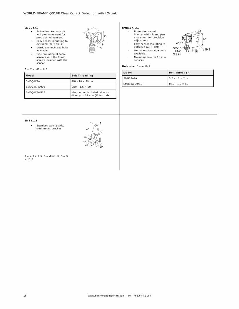
SMBQ4X..• Swivel bracket with tilt
and pan movement forprecision adjustment
• Easy sensor mounting toextruded rail T-slots
• Metric and inch size boltsavailable
• Side mounting of somesensors with the 3 mmscrews included with thesensor
40
43
AB
B = 7 × M3 × 0.5
Model Bolt Thread (A)
SMBQ4XFA 3/8 - 16 × 2¼ in
SMBQ4XFAM10 M10 - 1.5 × 50
SMBQ4XFAM12 n/a; no bolt included. Mountsdirectly to 12 mm (½ in) rods
SMB18AFA..• Protective, swivel
bracket with tilt and panmovement for precisionadjustment
• Easy sensor mounting toextruded rail T-slots
• Metric and inch size boltsavailable
• Mounting hole for 18 mmsensors
51
51
44
3/8-16 UNC
X 2 in.ø19.8
ø18.1
Hole size: B = ø 18.1
Model Bolt Thread (A)
SMB18AFA 3/8 - 16 × 2 in
SMB18AFAM10 M10 - 1.5 × 50
SMB312S
• Stainless steel 2-axis,side-mount bracket 46
B
C
A
3220
A = 4.3 × 7.5, B = diam. 3, C = 3× 15.3
WORLD-BEAM® QS18E Clear Object Detection with IO-Link
18 www.bannerengineering.com - Tel: 763.544.3164

8 Contact UsCorporate Headquarters
Address:Banner Engineering Corporate9714 Tenth Avenue NorthMinneapolis, Minnesota 55441, USA
Phone: +1 763 544 3164Website: www.bannerengineering.com
Europe
Address:Banner Engineering EMEAPark Lane Culliganlaan 2FDiegem B-1831, Belgium
Phone: +32 (0)2 456 0780Website: www.bannerengineering.com/euEmail: [email protected]
Turkey
Address:Banner Engineering TurkeyBarbaros Mah. Uphill Court Towers A Blok D:4934746 Batı Ataşehir Istanbul Türkiye
Phone: +90 216 688 8282Website: www.bannerengineering.com.trEmail: [email protected]
India
Address:Banner Engineering India Pune Head QuartersOffice No. 1001, 10th Floor Sai Capital, Opp. ICC Senapati Bapat RoadPune 411016, India
Phone: +91 (0) 206 640 5624Website: www.bannerengineering.co.inEmail: [email protected]
Mexico
Address:Banner Engineering de Mexico Monterrey Head OfficeEdificio VAO Av. David Alfaro Siqueiros No.103 Col. Valle Oriente C.P.66269San Pedro Garza Garcia, Nuevo Leon, Mexico
Phone: +52 81 8363 2714 or 01 800 BANNERE (toll free)Website: www.bannerengineering.com.mxEmail: [email protected]
Brazil
Address:Banner do BrasilRua Barão de Teffé nº 1000, sala 54Campos Elíseos, Jundiaí - SP, CEP.: 13208-761, Brasil
Phone: +1 763 544 3164Website: www.bannerengineering.com.brEmail: [email protected]
China
Address:Banner Engineering Shanghai Rep OfficeXinlian Scientific Research Building Level 12, Building 21535 Hongmei Road, Shanghai 200233, China
Phone: +86 212 422 6888Website: www.bannerengineering.com.cnEmail: [email protected]
Japan
Address:Banner Engineering JapanCent-Urban Building 305 3-23-15 Nishi-Nakajima Yodogawa-KuOsaka 532-0011, Japan
Phone: +81 (0)6 6309 0411Website: www.bannerengineering.co.jpEmail: [email protected]
Taiwan
Address:Banner Engineering Taiwan8F-2, No. 308 Section 1, Neihu RoadTaipei 114, Taiwan
Phone: +886 (0)2 8751 9966Website: www.bannerengineering.com.twEmail: [email protected]
WORLD-BEAM® QS18E Clear Object Detection with IO-Link
www.bannerengineering.com - Tel: 763.544.3164 19

9 Banner Engineering Corp. Limited WarrantyBanner Engineering Corp. warrants its products to be free from defects in material and workmanship for one year following the date of shipment. Banner Engineering Corp.will repair or replace, free of charge, any product of its manufacture which, at the time it is returned to the factory, is found to have been defective during the warrantyperiod. This warranty does not cover damage or liability for misuse, abuse, or the improper application or installation of the Banner product.
THIS LIMITED WARRANTY IS EXCLUSIVE AND IN LIEU OF ALL OTHER WARRANTIES WHETHER EXPRESS OR IMPLIED (INCLUDING, WITHOUT LIMITATION,ANY WARRANTY OF MERCHANTABILITY OR FITNESS FOR A PARTICULAR PURPOSE), AND WHETHER ARISING UNDER COURSE OF PERFORMANCE, COURSEOF DEALING OR TRADE USAGE.
This Warranty is exclusive and limited to repair or, at the discretion of Banner Engineering Corp., replacement. IN NO EVENT SHALL BANNER ENGINEERING CORP. BELIABLE TO BUYER OR ANY OTHER PERSON OR ENTITY FOR ANY EXTRA COSTS, EXPENSES, LOSSES, LOSS OF PROFITS, OR ANY INCIDENTAL,CONSEQUENTIAL OR SPECIAL DAMAGES RESULTING FROM ANY PRODUCT DEFECT OR FROM THE USE OR INABILITY TO USE THE PRODUCT, WHETHERARISING IN CONTRACT OR WARRANTY, STATUTE, TORT, STRICT LIABILITY, NEGLIGENCE, OR OTHERWISE.
Banner Engineering Corp. reserves the right to change, modify or improve the design of the product without assuming any obligations or liabilities relating to any productpreviously manufactured by Banner Engineering Corp. Any misuse, abuse, or improper application or installation of this product or use of the product for personal protectionapplications when the product is identified as not intended for such purposes will void the product warranty. Any modifications to this product without prior express approvalby Banner Engineering Corp will void the product warranties. All specifications published in this document are subject to change; Banner reserves the right to modify productspecifications or update documentation at any time. Specifications and product information in English supersede that which is provided in any other language. For the mostrecent version of any documentation, refer to: www.bannerengineering.com.
WORLD-BEAM® QS18E Clear Object Detection with IO-Link
20 www.bannerengineering.com - Tel: 763.544.3164