


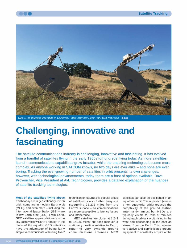
O3b 2.4m antennas operating in California. Photo … · O3b 2.4m antennas operating in California....
7
www.satellite-evolution.com | September/October 2016 36 Satellite Tracking O3b 2.4m antennas operating in California. Photo courtesy Hung Tran, O3b Networks Challenging, innovative and fascinating The satellite communications industry is challenging, innovative and fascinating. It has evolved from a handful of satellites flying in the early 1960s to hundreds flying today. As more satellites launch, communications capabilities grow broader, while the enabling technologies become more complex. As anyone working in SATCOM knows, no two days are ever alike – and none are ever boring. Tracking the ever-growing number of satellites in orbit presents its own challenges, however, with technological advancements, today there are a host of options available. Dave Provencher, Vice President at AvL Technologies, provides a detailed explanation of the nuances of satellite tracking technologies. Most of the satellites flying above Earth today are in geostationary (GEO) orbit, some are in medium Earth orbit (MEO), and even more – including the International Space Station (ISS) – are in low Earth orbit (LEO). From Earth, GEO satellites appear stationary in the sky as they follow Earth’s rotation in the plane of the equator. GEO satellites have the advantage of being fairly simple to communicate with using ‘fixed’ ground antennas. But this popular group of satellites is also further away – a staggering 22,236 miles from the Earth’s surface – so communications are more susceptible to latency issues and interference. MEO satellites are closer at 1,243 to 22,236 miles, but don’t maintain a stationary position relative to Earth, requiring very dynamic ground communications antennas. MEO satellites can also be positioned in an equatorial orbit. This approach (versus a non-equatorial orbit) reduces the complexity of the ground station antenna dynamics, but MEOs are typically visible for tens of minutes during each orbital circuit, rising in the west and descending in the east as viewed from the Earth. This requires very active and sophisticated ground equipment to constantly acquire at the
Transcript of O3b 2.4m antennas operating in California. Photo … · O3b 2.4m antennas operating in California....
www.satellite-evolution.com | September/October 201636
Satellite Tracking
O3b 2.4m antennas operating in California. Photo courtesy Hung Tran, O3b Networks
Challenging, innovative andfascinatingThe satellite communications industry is challenging, innovative and fascinating. It has evolvedfrom a handful of satellites flying in the early 1960s to hundreds flying today. As more satelliteslaunch, communications capabilities grow broader, while the enabling technologies become morecomplex. As anyone working in SATCOM knows, no two days are ever alike – and none are everboring. Tracking the ever-growing number of satellites in orbit presents its own challenges,however, with technological advancements, today there are a host of options available. DaveProvencher, Vice President at AvL Technologies, provides a detailed explanation of the nuancesof satellite tracking technologies.
Most of the satellites flying aboveEarth today are in geostationary (GEO)orbit, some are in medium Earth orbit(MEO), and even more – including theInternational Space Station (ISS) – arein low Earth orbit (LEO). From Earth,GEO satellites appear stationary in thesky as they follow Earth’s rotation in theplane of the equator. GEO satelliteshave the advantage of being fairlysimple to communicate with using ‘fixed’
ground antennas. But this popular groupof satellites is also further away – astaggering 22,236 miles from theEarth’s surface – so communicationsare more susceptible to latency issuesand interference.
MEO satellites are closer at 1,243to 22,236 miles, but don’t maintain astationary position relative to Earth,requir ing very dynamic groundcommunications antennas. MEO
satellites can also be positioned in anequatorial orbit. This approach (versusa non-equatorial orbit) reduces thecomplexity of the ground stationantenna dynamics, but MEOs aretypically visible for tens of minutesduring each orbital circuit, rising in thewest and descending in the east asviewed from the Earth. This requiresvery active and sophisticated groundequipment to constantly acquire at the
tracking.pmd 20/10/2016, 18:0436
www.satellite-evolution.com | September/October 201638
Satellite Tracking
point of ascension, track across thevisible arc, and quickly re-trace to thepoint of ascension – over and over.Continuous communications with otherground stations requires multiple,evenly-spaced satellites in the sameorbit and complex ground stationequipment that must acquire and trackthese constantly moving targets.
LEO satellites are closer still at 99to 1,243 miles above Ear th. LEOsatellites are typically visible for minutesper orbit, so a LEO constellationrequires many satellites to maintainconstant communications in a givenarea.
Satellite orbit challengesGEO satellites only appear to bestationary as viewed from Earth. Tobegin with, the Earth’s rotation isimperfect: The north-south axis ofrotation actually wobbles over time.GEO satellite orbits are also affectedby gravitational attraction from the sunand moon, as well as solar wind(charged particles emitted by the sun).To minimise these effects, modern GEOsatellites are equipped with efficient on-board thrusters and sufficient thrusterpropellant to maintain the desired orbitstability over the design life of thesatellite, typically 15 years. Thesethrusters can be commanded fromsatellite control facilities on Earth (viaan on-board command communicationantenna) to produce very precise orbitaladjustments that compensate forunwanted satellite motion, a techniqueknown as station-keeping. When thepropellant is consumed their orbits
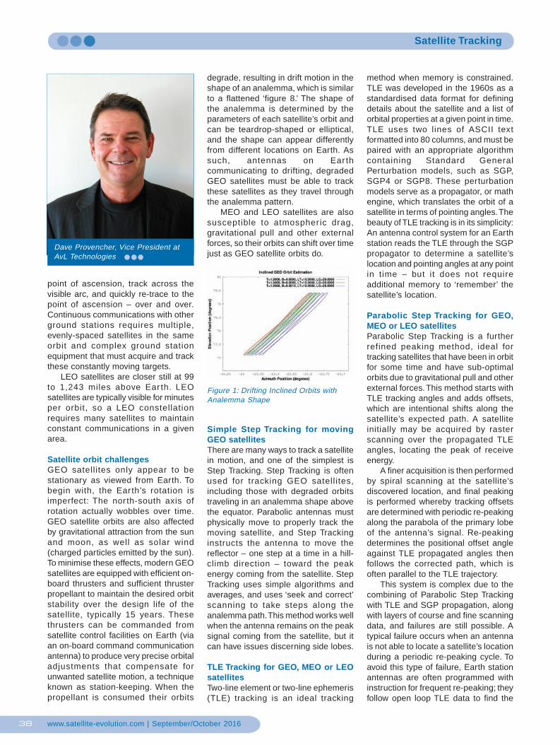
degrade, resulting in drift motion in theshape of an analemma, which is similarto a flattened ‘figure 8.’ The shape ofthe analemma is determined by theparameters of each satellite’s orbit andcan be teardrop-shaped or elliptical,and the shape can appear differentlyfrom different locations on Earth. Assuch, antennas on Ear thcommunicating to drifting, degradedGEO satellites must be able to trackthese satellites as they travel throughthe analemma pattern.
MEO and LEO satellites are alsosusceptible to atmospheric drag,gravitational pull and other externalforces, so their orbits can shift over timejust as GEO satellite orbits do.
Simple Step Tracking for movingGEO satellitesThere are many ways to track a satellitein motion, and one of the simplest isStep Tracking. Step Tracking is oftenused for tracking GEO satell ites,including those with degraded orbitstraveling in an analemma shape abovethe equator. Parabolic antennas mustphysically move to properly track themoving satellite, and Step Trackinginstructs the antenna to move thereflector – one step at a time in a hill-climb direction – toward the peakenergy coming from the satellite. StepTracking uses simple algorithms andaverages, and uses ‘seek and correct’scanning to take steps along theanalemma path. This method works wellwhen the antenna remains on the peaksignal coming from the satellite, but itcan have issues discerning side lobes.
TLE Tracking for GEO, MEO or LEOsatellitesTwo-line element or two-line ephemeris(TLE) tracking is an ideal tracking
method when memory is constrained.TLE was developed in the 1960s as astandardised data format for definingdetails about the satellite and a list oforbital properties at a given point in time.TLE uses two lines of ASCII textformatted into 80 columns, and must bepaired with an appropriate algorithmcontaining Standard GeneralPerturbation models, such as SGP,SGP4 or SGP8. These perturbationmodels serve as a propagator, or mathengine, which translates the orbit of asatellite in terms of pointing angles. Thebeauty of TLE tracking is in its simplicity:An antenna control system for an Earthstation reads the TLE through the SGPpropagator to determine a satellite’slocation and pointing angles at any pointin time – but it does not requireadditional memory to ‘remember’ thesatellite’s location.
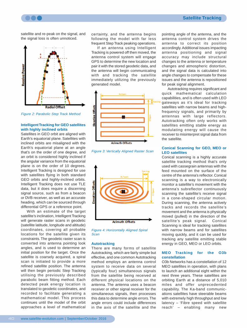
Parabolic Step Tracking for GEO,MEO or LEO satellitesParabolic Step Tracking is a furtherrefined peaking method, ideal fortracking satellites that have been in orbitfor some time and have sub-optimalorbits due to gravitational pull and otherexternal forces. This method starts withTLE tracking angles and adds offsets,which are intentional shifts along thesatellite’s expected path. A satelliteinitially may be acquired by rasterscanning over the propagated TLEangles, locating the peak of receiveenergy.
A finer acquisition is then performedby spiral scanning at the satellite’sdiscovered location, and final peakingis performed whereby tracking offsetsare determined with periodic re-peakingalong the parabola of the primary lobeof the antenna’s signal. Re-peakingdetermines the positional offset angleagainst TLE propagated angles thenfollows the corrected path, which isoften parallel to the TLE trajectory.
This system is complex due to thecombining of Parabolic Step Trackingwith TLE and SGP propagation, alongwith layers of course and fine scanningdata, and failures are still possible. Atypical failure occurs when an antennais not able to locate a satellite’s locationduring a periodic re-peaking cycle. Toavoid this type of failure, Earth stationantennas are often programmed withinstruction for frequent re-peaking; theyfollow open loop TLE data to find the
Figure 1: Drifting Inclined Orbits withAnalemma Shape
Dave Provencher, Vice President atAvL Technologies
tracking.pmd 20/10/2016, 18:0438
www.satellite-evolution.com | September/October 201640
Satellite Tracking
satellite and re-peak on the signal, andthe signal loss is often unnoticed.
Intelligent Tracking for GEO satelliteswith highly inclined orbitsSatellites in GEO orbit are aligned withEarth’s equatorial plane. Satellites withinclined orbits are misaligned with theEarth’s equatorial plane at an anglethat’s on the order of one degree, andan orbit is considered highly inclined ifthe angular variance from the equatorialplane is on the order of 10 degrees.Intelligent Tracking is designed for usewith satellites flying in both standardGEO orbits and highly-inclined orbits.Intelligent Tracking does not use TLEdata, but it does require a discerningsignal source, such as from a beaconor DVB receiver, as well as an accurateheading, which can be sourced throughdifferential GPS or a reference point.
With an estimate of the targetsatellite’s inclination, Intelligent Trackingwill generate raster scans in geodetic(satellite latitude, longitude and altitude)coordinates, covering all probablelocations for the satellite given itsconstraints. The geodetic raster scan isconverted into antenna pointing lookangles, and is used to determine aninitial position for the target. Once thesatellite is coarsely acquired, a spiralscan is initiated to provide a morerefined satellite position. The antennawill then begin periodic Step Trackingutil ising the previously describedparabolic beam fitting method. Eachdetected peak energy location istranslated to geodetic coordinates, andrecorded to facilitate generating amathematical model. This processcontinues until the model of the orbitapproaches a level of mathematical
cer tainty, and the antenna beginsfollowing the model with far lessfrequent Step Track peaking operations.
If an antenna using IntelligentTracking is powered off then moved, theantenna control system will engageGPS to determine the new location andpair it with the stored geodetic data, andthe antenna will begin communicatingwith and tracking the satell iteimmediately utilizing the previouslygenerated model.
AutotrackingThere are many forms of satelliteAutotracking, which are fairly simple buteffective, and one common Autotrackingmethod employs an antenna controlsystem to receive data on several(typically four) simultaneous signalsfrom the satellite being received atdifferent physical locations on theantenna. The antenna uses a beaconreceiver or other signal receiver for thesimultaneous signals, then processesthis data to determine angle errors. Theangle errors could include differencesin the axis of the satellite and the
pointing angle of the antenna, and theantenna control system drives theantenna to correct its positionaccordingly. Additional issues impactingantenna positioning and signalaccuracy may include structuralchanges to the antenna or temperaturechanges and atmospheric distortion,and the signal data is calculated intoangle changes to compensate for theseissues and the antenna is repositionedfor peak signal alignment.
Autotracking requires significant andquick mathematical calculationcapabilities, and is often used with LEOgateways as it’s ideal for trackingsatellites with narrow beams and high-frequency signals, and primarily byantennas with large reflectors.Autotracking often only works withsatellites emitting stable energy asmodulating energy will cause thereceiver to misinterpret signal data fromthe satellite.
Conical Scanning for GEO, MEO orLEO satellitesConical scanning is a highly accuratesatellite tracking method that’s onlyused with cassegrain antennas with thefeed mounted on the surface of thecentre of the antenna’s reflector. Conicalscanning is a way to electronicallymonitor a satellite’s movement with theantenna’s subreflector continuouslyscanning the satellite’s receive signalin a cone-shaped circular motion.During scanning, the antenna activelytracks and records the satell ite’smovement and the antenna is physicallymoved (pulled) in the direction of thesatell ite’s peak signal. ConicalScanning is ideal for tracking satelliteswith narrow beams and for satellitesmoving quickly, and it can be used fortracking any satellite emitting stableenergy in GEO, MEO or LEO orbits.
MEO Tracking for the O3bconstellationO3b Networks has a constellation of 12MEO satellites in operation, with plansto launch an additional eight within thenext three years. These satellites areorbiting Earth at a distance of 5,010miles and offer unprecedentedcapability. The Ka-band communic-ations satellites have steerable beamswith extremely high throughput and lowlatency – ‘Fibre speed with satellitereach’ – enabling many new
Figure 2: Parabolic Step Track Method
Figure 4: Horizontally Aligned SpiralScan
Figure 3: Vertically Aligned Raster Scan
tracking.pmd 20/10/2016, 18:0440
www.satellite-evolution.com | September/October 201642
Satellite Tracking
communications applications formilitary, marine and other uses.
AvL Technologies was engaged todesign and build a family oftransportable terminal antenna systemsfor O3b Networks in sizes ranging from85cm to 2.4m, with all beingtransportable in durable transit casesand to be set up and on-the-air withintwo hours. The systems operate with apair of tandem-operation antennas withone antenna actively communicatingwith a satellite while the other is onstandby awaiting handoff from the first.
Essential to being on-the-air in aminimal amount of time is AvL’s AAQantenna control system. An O3b-proprietary module was added to theAAQ that employs data from theantennas’ GPS sensors, inclinometers,pitch and roll sensors, O3b’s satellite
schedule, and O3b TLE data. This datais used to calculate both the antennas’pedestal angles and the world angle forthe expected position of the satellite,and sample positions are recorded intomemory. The AAQ then creates a newcoordinate transform (a translation fromtrue world angles to motor-directedangles), and the first antenna goes liveon the air for transmit and receive, whilethe second antenna continues learning.When the first antenna reaches the farhorizon, the antennas’ roles switch.After several satellite passes, theantennas discontinue shadow learningto reduce their duty cycles, and revertto less frequent scanning. The antennasuse periodic re-peaking during thelearning process, and once the shadowlearning is complete, the system willperform a learning operation for one
satellite pass, once a day, to keep themodel up to date.
ConclusionThough the first satellites were flyingaround Earth in the early 1960s, thelaws of physics that govern how tocommunicate with a satellite thousandsof miles above remain the same.However, modern satellites offer morepower and signal variations, and currentantenna control systems offer infiniteadvances in efficient signal processingand mathematical models to manageamounts of data that were unthinkable50 years ago. Thanks to the engineersamong us, we now have limitlesssatellite communications capabilities –and many innovative ways to track andengage these mobile (yet seeminglymotionless) satellites.
Photo courtesy of Shutterstock
AvL Technologies wasengaged to design and
build a family oftransportable terminal
antenna systems for O3bNetworks in sizes ranging
from 85cm to 2.4m
tracking.pmd 20/10/2016, 18:0442