O. Lavigne, R. Mévrel, M. Poulain, C. Rio, M.-H. Vidal ... of Thermal Barrier Coatings for Turbine...
11
Issue 3 - November 2011 - Thermal Barrier Coatings for Turbine Blades AL03-03 1 High Temperature Materials Performance and Degradation Mechanisms of Thermal Barrier Coatings for Turbine Blades: a Review of Onera Activities M.-P. Bacos, J.-M. Dorvaux, O. Lavigne, R. Mévrel, M. Poulain, C. Rio, M.-H. Vidal-Sétif (Onera) E-mail: [email protected] T hermal barrier coatings are used to protect blades and vanes in the hot sections of gas turbines. They consist of a thick porous ceramic layer deposited on a alumina forming metallic bond coat in contact with the nic- kel-based superalloy substrate. They are designed to prolong the compo- nents lifetimes or to increase gas temperature, and therefore efficiency. In service, the structure and composition of the various layers evolve, due to sintering of the ceramic layer, oxidation of the bond coat, and interdiffusion phenomena with the substrate. As a result, the properties of each layer are affected, as is the interfacial toughness. These evolutions, combined with applied external stresses, may lead to bond coat rumpling, crack formation at the bond coat/ceramic interface and the ceramic layer may eventually spall off. In addition to these intrinsic degradation modes, interactions with the environment can accelerate the system degradation. This paper reviews the aging phenomena occurring in thermal barrier coatings at high temperatures and describes their degradation mechanisms, with illustrations from service experience and laboratory tests Introduction Thermal Barrier Coatings (TBCs) were developed in the 70’s to meet engine manufacturers’ requests for improving engine per- formance and fuel efficiency (increased operating temperatures of turbine section) while reducing emissions and costs (simpli- fied cooling air system, increased component lifetime, reduced maintenance cost, etc.). Today, TBCs are widely used to pro- tect critical metallic parts of aircraft as well as land-based gas turbines (blades, vanes, seals and combustor chambers) from the surrounding hot gases. However TBCs in service are prone to intrinsic and extrinsic degradation phenomena [1] which may considerably restrict their potential. Both academic and industrial research is therefore underway to improve TBCs’ reliability and performance [2]. This paper gives an overview of some activi- ties carried out at Onera in this field over the past ten years in connection with the state-of-the-art. It focuses on TBC systems which are deposited on the most stressed high pressure turbine blades. TBCs: a multilayer, multifunction system TBCs are a multilayer system (figure 1) with each layer having a specific function and requirement. The top layer provides ther- mal insulation and consists of a porous ceramic coating with low thermal conductivity. It must also have a high melting point, good oxidation and corrosion resistance, a thermal expansion coefficient closer to that of the underlying metal in order to reduce thermal mismatch stresses, high toughness and strain tolerance. Yttria partially stabilized zirconia (8 wt. % YPSZ) is commonly used as it is one of the few available materials which satisfies all the requirements. It is deposited on rotating compo- nents as a layer of about 150 µm by the EB-PVD process (Elec- tron Beam Physical Vapor Deposition). The resulting columnar microstructure shows high strain compliance and good resis- tance to erosion, but leads to moderately low thermal conduc- tivity (~ 1.5 W.m -1 .K -1 ). A temperature drop of up to 150°C can be achieved through the top layer, thus reducing accordingly the underlying metal temperature.
Transcript of O. Lavigne, R. Mévrel, M. Poulain, C. Rio, M.-H. Vidal ... of Thermal Barrier Coatings for Turbine...

Issue 3 - November 2011 - Thermal Barrier Coatings for Turbine Blades AL03-03 1
High Temperature Materials
Performance and Degradation Mechanisms of Thermal Barrier
Coatings for Turbine Blades: a Review of Onera Activities
M.-P. Bacos, J.-M. Dorvaux, O. Lavigne, R. Mévrel, M. Poulain, C. Rio, M.-H. Vidal-Sétif (Onera)
E-mail: [email protected]
Thermal barrier coatings are used to protect blades and vanes in the hot sections of gas turbines. They consist of a thick porous ceramic layer
deposited on a alumina forming metallic bond coat in contact with the nic-kel-based superalloy substrate. They are designed to prolong the compo-nents lifetimes or to increase gas temperature, and therefore efficiency. In service, the structure and composition of the various layers evolve, due to sintering of the ceramic layer, oxidation of the bond coat, and interdiffusion phenomena with the substrate. As a result, the properties of each layer are affected, as is the interfacial toughness. These evolutions, combined with applied external stresses, may lead to bond coat rumpling, crack formation at the bond coat/ceramic interface and the ceramic layer may eventually spall off. In addition to these intrinsic degradation modes, interactions with the environment can accelerate the system degradation. This paper reviews the aging phenomena occurring in thermal barrier coatings at high temperatures and describes their degradation mechanisms, with illustrations from service experience and laboratory tests
Introduction
Thermal Barrier Coatings (TBCs) were developed in the 70’s to meet engine manufacturers’ requests for improving engine per-formance and fuel efficiency (increased operating temperatures of turbine section) while reducing emissions and costs (simpli-fied cooling air system, increased component lifetime, reduced maintenance cost, etc.). Today, TBCs are widely used to pro-tect critical metallic par ts of aircraft as well as land-based gas turbines (blades, vanes, seals and combustor chambers) from the surrounding hot gases. However TBCs in service are prone to intrinsic and extrinsic degradation phenomena [1] which may considerably restrict their potential. Both academic and industrial research is therefore underway to improve TBCs’ reliability and performance [2]. This paper gives an overview of some activi-ties carried out at Onera in this field over the past ten years in connection with the state-of-the-ar t. It focuses on TBC systems which are deposited on the most stressed high pressure turbine blades.
TBCs: a multilayer, multifunction system
TBCs are a multilayer system (figure 1) with each layer having a specific function and requirement. The top layer provides ther-mal insulation and consists of a porous ceramic coating with low thermal conductivity. It must also have a high melting point, good oxidation and corrosion resistance, a thermal expansion coefficient closer to that of the underlying metal in order to reduce thermal mismatch stresses, high toughness and strain tolerance. Yttria par tially stabilized zirconia (8 wt. % YPSZ) is commonly used as it is one of the few available materials which satisfies all the requirements. It is deposited on rotating compo-nents as a layer of about 150 µm by the EB-PVD process (Elec-tron Beam Physical Vapor Deposition). The resulting columnar microstructure shows high strain compliance and good resis-tance to erosion, but leads to moderately low thermal conduc-tivity (~ 1.5 W.m-1.K-1). A temperature drop of up to 150°C can be achieved through the top layer, thus reducing accordingly the underlying metal temperature.

Issue 3 - November 2011 - Thermal Barrier Coatings for Turbine Blades AL03-03 2
The ceramic insulating layer is deposited on an oxidation resis-tant metallic layer (the bond coat) which, during service, forms a protective oxide, mostly alumina. This thermally grown oxide scale (TGO) has to be perfectly adherent to both the top layer and the bond coat in order to insure the chemical and mecha-nical compatibility of the whole system. The bond coat is for example a diffusion platinum modified nickel aluminide which is obtained by deposition of a thin electroplated platinum layer followed by a vapor phase aluminizing process. The underlying substrate is the first generation nickel-based single crystal su-peralloy AM11 [3].
Figure 1 - Typical Thermal Barrier Coating for rotating turbine components
TBCs evolution during service
In service, TBCs are exposed to oxidizing combustion gases and the external surface temperatures can reach about 1200°C. In these conditions, temperature driven phenomena occur such as sintering of the porous ceramic layer, oxidation of the bond coat and interdiffusion with the substrate. Consequently, the structure and composition of the various layers evolve and their properties are affected, as is the interfacial toughness. It will be shown that these evolutions combi-ned with the applied thermal and mechanical stresses may cause the ceramic layer to spall off in the end.
Aging of the ceramic top layer: sintering and phase transformation
Sintering of the top layer occurs rapidly from the first aging times at 1100°C, initially over short length scales and then more slowly over longer length scales. At first, the feather-like edges of the columns are rounded off by surface diffusion and progressively transform into lines of disconnected closed pores. Random bridge formation
between the columns follows (figure 2). These sintering effects are accelerated at higher temperatures. A consequence of these widely documented phenomena [4] is a drop in the top coat strain com-pliance and thermal insulation capability as illustrated in figure 2 (from [5]). A higher thermal conductivity of the ceramics increases the surface temperature of the metal with deleterious effects on the component life duration. Furthermore an increased Young’s modulus of the top coat leads to higher energy stored in the system and can induce anticipated spallation of the TBC (see § Energetic approach of TBC failure, box 3).
Figure 2 - Effect of sintering on 8YPSZ EB-PVD ceramic top coat microstruc-ture and thermal conductivity (measured at room temperature in air atmos-phere with a CO2 - laser flash technique)
When inter-columnar sintering is sufficiently large, in-plane tensile stresses appear which cause cracks to initiate and grow, giving a mud-like pattern upon cooling [5,6]. These cracks going through the top coat thickness facilitate CMAS infiltration (see § TBC interactions with environment).
Moreover, in the case of YPSZ coatings, crystallographic phase trans-formations are well known to occur during aging from 1200°C [7]. The initial metastable tetragonal t’ phase transforms at high tempe-rature into a mixture of yttria-rich cubic phase and yttria-poor tetra-gonal phase t which in turn may transform into a monoclinic phase on cooling. As a consequence, cracks due to transformation volume mismatch can appear and the thermal conductivity of the coating may be modified. Nevertheless, Onera work showed [5] from phase frac-tion estimation by X-ray diffraction and thermal conductivity data as a function of yttria concentration [8] that the phase transformation contributes less than 10% to the evolution of the thermal conductivity of the top coat. This effect is thus of second order compared to the sintering effect.
Bond coat oxidation
In service, the initially -NiPtAl single phased bond coat loses part of its aluminum content by formation of a highly protective alumina scale which slowly grows according to typical -alumina growth kinetics, eventually following a transient oxidation period. Never-theless, some factors can affect the properties of this oxide scale and possibly weaken the resistance of the bond coat / top coat interface, thus contributing to the degradation of the thermal barrier system.
1 AM1 composition [wt. %] : Ni base, 6.5 Co, 7.8 Cr, 2 Mo, 5.7 W, 5.2 Al, 1.1 Ti, 7.9 Ta
Hot gases
∼1200 °C
1050 °C
20 µm
8YPSZEB-PVD
TGO
Bond Coat (NiPtAl)
Superalloy (AM1)
Cooling air
as deposeted
300h/1100°C
2 µm
2 µmAgeing temperature [°C]
Thermal conductivity[W.m-1.K-1]
as-depositedaged 10 haged 100 haged 300 h
as-deposited 1100 1200 1300
2.5
2.0
1.5
1.0
0.5
0.0
Issue 3 - November 2011 - Thermal Barrier Coatings for Turbine Blades AL03-03 3
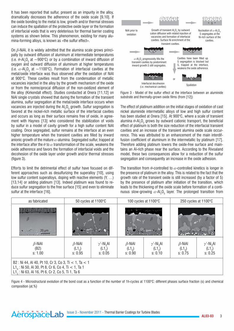
It has been reported that sulfur, present as an impurity in the alloy, dramatically decreases the adherence of the oxide scale [9,10]. If the oxide bonding to the metal is low, growth and/or thermal stresses can induce the spallation of the protective oxide layer or the formation of interfacial voids that is very deleterious for thermal barrier coating systems as shown below. This phenomenon, existing for many alu-mina-forming alloys, is known as «the sulfur effect».
On -NiAl, it is widely admitted that the alumina scale grows princi-pally by outward diffusion of aluminum at intermediate temperatures (i.e. -Al2O3 at 900°C) or by a combination of inward diffusion of oxygen and outward diffusion of aluminum at higher temperatures (i.e. -Al2O3 at 1100°C). Formation of interfacial cavities at the metal/oxide interface was thus observed after the oxidation of NiAl at 900°C. These cavities result from the condensation of metallic vacancies injected in the alloy by the growth mechanism of the oxide or from the nonreciprocal diffusion of the non-oxidized element of the alloy (Kirkendall effect). Studies conducted at Onera [11,12] on NiAl single crystals showed that during the formation of the transient alumina, sulfur segregation at the metal/oxide interface occurs when vacancies are injected during the Al2O3 growth. Sulfur segregation is favored at the nickel-rich metallic surface of the interfacial cavities and occurs as long as their surface remains free of oxide, in agree-ment with Haynes [13] who considered the stabilization of voids by sulfur in a model of cavity growth for a high sulfur content NiAl coating. Once segregated, sulfur remains at the interface at an even higher temperature when the transient cavities are filled by inward anionic growth of the mature -alumina. Segregated sulfur, trapped at the interface after the to transformation of the scale, weakens the oxide adherence and favors the formation of interfacial voids and the decohesion of the oxide layer under growth and/or thermal stresses (figure 3).
Efforts to limit the detrimental effect of sulfur have focused on dif-ferent approaches such as desulfurizing the superalloy [10], using low sulfur content superalloys, doping with reactive elements (Y, …) [13,14] or adding platinum [13]. Indeed platinum was found to re-duce sulfur segregation to the free surface [15] and even to eliminate sulfur at the interface [16].
Figure 3 - Model of the sulfur effect at the interface between an aluminide substrate and thermally-grown oxide films (from [12])
The effect of platinum addition on the initial stages of oxidation of cast nickel aluminide intermetallic alloys of low and high sulfur content has been studied at Onera [15]. At 900°C, where a scale of transient alumina -Al2O3 grows by outward cationic transport, the beneficial effect of platinum is both the size reduction of the interfacial transient cavities and an increase of the transient alumina oxide scale occur-rence. This was attributed to an enhancement of the main interdif-fusion coefficient of aluminum in the intermetallic by platinum [17]. Therefore adding platinum lowers the oxide-free surface and main-tains an Al-rich phase near the surface. According to the Rivoaland model, these two consequences allow for a reduction of the sulfur segregation and consequently an increase in the oxide adhesion.
The transition from -controlled to -controlled kinetics is longer in the presence of platinum in the alloy. This is related to the fact that the growth rate of the transient oxide is still increased (by a factor of 5) by the presence of platinum after initiation of the transition, which leads to the thickening of the oxide scale before formation of a conti-nuous slow-growing -Al2O3 layer. The prolonged transition from
as fabricated 50 cycles at 1100°C 100 cycles at 1100°C 250 cycles at 1100°C
-NiAl(B2)
s: 1.00
-NiAl (L10)
s: 0.95
’-Ni3Al (L12)
s: 0.05
-NiAl (L10)
s: 0.90
’-Ni3Al (L12)
s: 0.10
-NiAl (L10)
s: 0.75
’-Ni3Al (L12)
s: 0.25
B2 : Ni 44, Al 40, Pt 10, Cr 3, Co 3, Ti < 1, Ta < 1L10 : Ni 50, Al 30, Pt 8, Cr 6, Co 4, Ti < 1, Ta 1L12 : Ni 63, Al 16, Pt 6, Cr 2, Co 5, Ti 1, Ta 6
Figure 4 - Microstructural evolution of the bond coat as a function of the number of 1h-cycles at 1100°C: different phases surface fraction (s) and chemical composition (at.%)
NiAl prior tooxidation
Growth of transient Al2O3 by outward cation diffusion with related injection of vacancies and formation of interfacial cavities. Surface Ni enrichment of the
transient cavities.
Nucleation of -Al2O3. S segregates at the
Ni-rich surface of the cavities.
-Al2O3 progressivity fills the transient cavities by predominant inward growth.S still segregates.
SS
SS
S
or
Cavities have been filled up. S segregation is blocked but S, trapped at the interface, weakens the oxide adherence.
Interfacial decohesion (i.e. mechanical cavities)
Spallation
20 µm
γ'
γ' γ'

Issue 3 - November 2011 - Thermal Barrier Coatings for Turbine Blades AL03-03 4
-controlled to -controlled kinetics observed in the presence of pla-tinum is proposed to favor the stress relaxation in the alumina scale.
Bond coat / superalloy interdiffusion
Besides the oxidation of the bond coat, thermal cycling of the TBC system promotes interdiffusion of various elements between the pla-tinum modified aluminide layer and the underlying superalloy subs-trate (AM1 in the present case). As a result, the aluminum content of the bond coat becomes lower and lower, so that the initially -NiPtAl single phase transforms into a ’-Ni3Al phase (figure 4). In addition to this inward diffusion of aluminum and platinum, outward diffusion of some elements of the substrate such as cobalt, chromium or tita-nium also contributes to phase transformation within the bond coat.It should be noted that the chemical composition of these two in-equilibrium phases remains constant whereas their volume fraction evolves during thermal cycling: as the initial Al-rich phase is reduced, the aged Al-poor phase extends. Moreover, next to the ’-Ni3Al phase (L12) a lamellar structure may be observed at room temperature, rela-ted to the reverse transformation of the -NiAl (B2) phase into the martensitic NiAl phase (L10) which takes place during the cooling and heating stage of thermal cycling. The occurrence of martensite main-ly depends on the Al and Pt content of the bond coat as well as on the nature and content of the diffused elements from the substrate. The phase transformations within the bond coat will have consequences on its mechanical behavior [18].
Intrinsic degradation mechanisms
Stress field and rumpling
As mentioned above, an interfacial stress field develops in thermal barrier systems during thermal cycling, resulting from oxidation growth stresses and thermal stresses due to thermal expansion mis-match between the top coat, the TGO and the bond coat. Piezospec-troscopy measurements performed at Onera clearly demonstrate that high compressive in-plane stresses (about 3 GPa) remain at room temperature within the TGO (figure 5, from [19,20]). At the same time, out-of-plane stresses exist because the interface is not flat. They cause the bond coat/TGO interface to deform so that a slight in-plane stress relaxation is observed, due to progressive interfacial roughe-ning, also called rumpling [21]. But resulting out-of-plane stresses also initiate local damage. As a result, geometrical incompatibilities in concave areas combined with voids formation related to oxidation
induce crack interfacial propagation, thus leading to sudden top coat spallation (figure 6). We note that the crack pathway is mixed (going along the TGO/top coat interface or through the TGO) as attested by fracture surface observations.
Large stresses produced in the bond coat by phase transformation, such as the martensitic transformation, may also effectively promote undulation growth. Rumpling is obviously governed by the creep re-sistance of the bond coat and the mechanical behavior of the highly compressed TGO. The mechanical behavior of the bond coat plays a key role in the relaxation of stresses induced by oxidation and mar-tensitic transformation. In particular, in order to describe the interface progressive roughening, it is essential to know the elastic viscoplas-tic law of the bond coat in the as-elaborated state and its evolution during thermal cycling linked to the arising phase transformations. An original technique - high temperature instrumented microindentation, up to 1000°C - has been developed at Onera (see box 1) to extract information on the mechanical behavior of the bond coat [22]. The mechanical properties of the different phases (hardness related to yield stress, elastic modulus, creep law) are investigated by means of indentation tests, which enable local measurement within individual phases. For instance, the indentation creep behavior is determined by applying a load of about 0.5 N, and by holding it during several thousand seconds (up to about 1 hour) at different temperatures. An inverse problem analysis is used (analytical approaches and finite element method simulation) to identify the variables of the constitu-tive law of the materials tested.
Figure 5 - Evolution of residual compressive in-plane stresses (C) in the TGO and arithmetical mean roughness (Ra) of the bond coat/TGO interface as a function of the number of 1h-cycles at 1100°C
Figure 6 - Interfacial geometrical incompatibilities generated by out-of plane stresses (N) and voids due to oxidation
C
C(G
Pa)
R a (µm
)
Ra
Number of 1h-cycles at 1100°C
3
2
1
0
6
5
4
3
2
1
0
0 50 100 150 200 250
NiPtAl 10 µm
TGO
8YPSZ
NiPtAl 10 µm
TGO
8YPSZ
C
N

Issue 3 - November 2011 - Thermal Barrier Coatings for Turbine Blades AL03-03 5
Box 1 - High temperature instrumented microindentation system
(B. Passilly, Onera – Department of Composite Materials and Structures)
General description - Principle
The vacuum chamber contains two translation stages (horizon-tal X and Y axis), on which the load sensor, the sample holder, the sample, and a furnace are fixed. This X-Y stage enables the horizontal sample to move from under a microscope to under the indenter. The indenter and the sample are located inside small furnaces which are separately resistively heated up to the test temperature (up to 1000°C). The displacements are measured using a differential capacitive technology.
Time, load and indenter displacement are recorded simultaneous-ly during the loading, holding and unloading phases.
Figure B1-01 - Microindentation equipment
Data analysis
Adapted from the approach by Sargent and Ashby - Indentation creep. Mat. Sci. Technol., 8 (1992) 594-601
Norton law 00
expn
QRT
σε εσ = ⋅ −
Penetration depth ( ) ( )1
220 exp
nn
calcQh t h B T nRT
= + ⋅ ⋅ −
• fitting experimental curves hexp
(t) for different T n, B(T)•variation in B(T) Q Figure B1-02 - Example: indentation creep (0.5 N load) of NiPtAl bond coat
Interface evolution modeling
In order to better understand the TBC degradation mechanisms, a semi-analytical model describing the interface evolution during thermal cycling is used at Onera. This model, which is based on Hutchinson studies [23], considers the TBC system as a macros-copic multilayered structure, in which complex behavior laws are used for each layer. It has to be specified that the creep law of the bond coat injected into the model is the one determined by high temperature instrumented microindentation and that the interfacial roughness is drawn as a sinusoidal undulation (figure 7). This computation is designed to quantify the interface roughening, re-lated to the in-plane and out-of-plane stress development with the aim of specifying a damage criterion. The model is being valida-ted by comparing its predictions with experimental observation of rumpling. Onera’s current work focuses on getting essential data in order to build a physically-based model, able to assess thermal barrier spalling on turbine blades.
Input data of the computation:Oxidation kinetic, martensitic transformation, hardening, creep laws, thermal
expansion coefficients, initial undulation geometry
Output data of the computation:In-plane and out-of-plane stresses (xx and yy)
Undulation amplification ()
Figure 7 - Semi-analytical modeling of the TBC multilayered structure
(6)
(1)
(2)
(3)
(4)
(5)
Vickers indenter
(1) indenter(2) microscope(3) sample(4) force sensor(5) micrometric translation tables(6) two furnaces
800°C 750°C
700°C
Time (s)
0 500 1000 1500 2000 2500 3000 3500 4000
Indentation depth (µm)
7
6
5
4
3
2
1
0
8YPS
ZTG
ONi
PtAl
Supe
rallo
y
YY
YY
XX XX
L
e(Al2O3)
Issue 3 - November 2011 - Thermal Barrier Coatings for Turbine Blades AL03-03 6
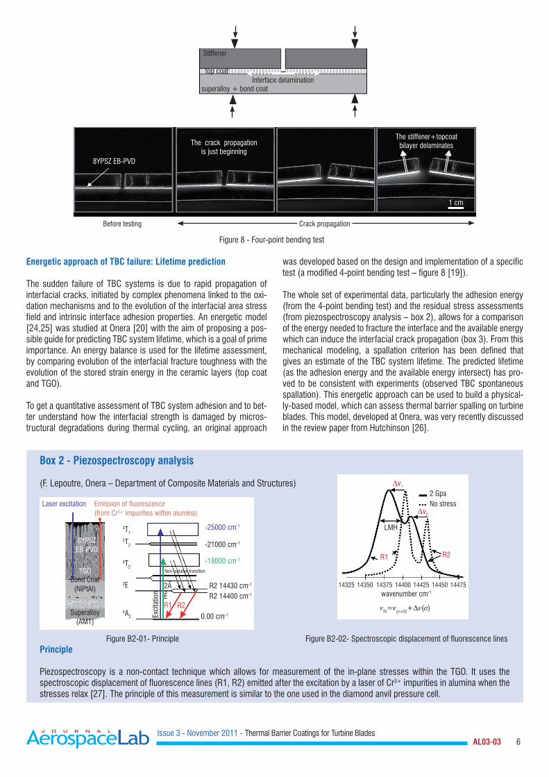
Energetic approach of TBC failure: Lifetime prediction
The sudden failure of TBC systems is due to rapid propagation of interfacial cracks, initiated by complex phenomena linked to the oxi-dation mechanisms and to the evolution of the interfacial area stress field and intrinsic interface adhesion properties. An energetic model [24,25] was studied at Onera [20] with the aim of proposing a pos-sible guide for predicting TBC system lifetime, which is a goal of prime importance. An energy balance is used for the lifetime assessment, by comparing evolution of the interfacial fracture toughness with the evolution of the stored strain energy in the ceramic layers (top coat and TGO).
To get a quantitative assessment of TBC system adhesion and to bet-ter understand how the interfacial strength is damaged by micros-tructural degradations during thermal cycling, an original approach
Figure 8 - Four-point bending test
was developed based on the design and implementation of a specific test (a modified 4-point bending test – figure 8 [19]).
The whole set of experimental data, particularly the adhesion energy (from the 4-point bending test) and the residual stress assessments (from piezospectroscopy analysis – box 2), allows for a comparison of the energy needed to fracture the interface and the available energy which can induce the interfacial crack propagation (box 3). From this mechanical modeling, a spallation criterion has been defined that gives an estimate of the TBC system lifetime. The predicted lifetime (as the adhesion energy and the available energy intersect) has pro-ved to be consistent with experiments (observed TBC spontaneous spallation). This energetic approach can be used to build a physical-ly-based model, which can assess thermal barrier spalling on turbine blades. This model, developed at Onera, was very recently discussed in the review paper from Hutchinson [26].
Box 2 - Piezospectroscopy analysis
(F. Lepoutre, Onera – Department of Composite Materials and Structures)
Figure B2-01- Principle Figure B2-02- Spectroscopic displacement of fluorescence linesPrinciple
Piezospectroscopy is a non-contact technique which allows for measurement of the in-plane stresses within the TGO. It uses the spectroscopic displacement of fluorescence lines (R1, R2) emitted after the excitation by a laser of Cr3+ impurities in alumina when the stresses relax [27]. The principle of this measurement is similar to the one used in the diamond anvil pressure cell.
Stiffener
top coat
superalloy + bond coatInterface delamination
8YPSZ EB-PVD
The crack propagation is just beginning
The stiffener+topcoat bilayer delaminates
1 cm
Crack propagationBefore testing
Laser excitation Emission of fluorescence(from Cr3+ impurities within alumina)
2T2
4T1
4T2
2E
4A2
-25000 cm-1
-21000 cm-1
-18000 cm-1
R2 14430 cm-1
R2 14400 cm-1
0.00 cm-1
R1 R2
8YPSZEB-PVD
TGOBond Coat
(NiPtAl)
Superalloy(AM1)
Exci
tatio
n
2AE
--
Non-radiative transition
2 GpaNo stress
LMH
R1 R2
v1
v2
14325 14350 14375 14400 14425 14450 14475wavenumber cm-1
Ri=(=0)+()

Issue 3 - November 2011 - Thermal Barrier Coatings for Turbine Blades AL03-03 7
Box 3 - Energetic approach of TBC failure
Figure B3-01 - Evolution of adhesion energy (GIIc) and available energy (W) for interfacial crack propagation during thermal cycling at 1100°C
Influence of experimental data on TBC lifetime prediction
It is to be noted that an experimental uncertainty is attached to the interfacial fracture toughness evolution, and that some parameters used for the elastic stored energy calculation also induce some inaccuracy. In particular, the top coat Young’s modulus, which increases during thermal cycling, due to sintering phenomena and environmental interactions (CMAS infiltration) must be precisely quantified in order to refine the lifetime prediction.
TBC interactions with environment
As already mentioned, the surface of TBCs on turbine blades and vanes located in the hottest sections of gas turbine engines can reach temperatures up to 1200°C in operating conditions. At such temperatures, thermal barrier coatings are susceptible to corro-sion by molten calcium-magnesium-alumino-silicates (CMAS) resulting from the ingestion of siliceous mineral debris (dust, sand, ash) contained in the hot gases arriving in the turbine. In the lite-rature, few studies [29,30] can be found investigating, on ex-ser-vice blades or vanes, the damage resulting from CMAS attack on the TBC, especially when the top coat is elaborated by EB-PVD [31]. The first studies conducted at Onera in this field have thus consisted of microstructural characterizations of the interaction between CMAS and EB-PVD TBC observed on high pressure tur-bine blades removed from service. The main results of this study are reported below.
The initially white TBC surface is covered after service by a brownish deposit strongly adhering to the blade surface. This deposit is present mainly on the pressure side and leading edge whereas a large part of the suction side surface is free from deposits (figure 9).
Figure 9 – After service high pressure turbine blade: pressure side covered by CMAS brownish deposit
Adhesionenergy G
IIC
Model predicted lifetime Experimental lifetime
Number of 1h-cycles at 1100°C
450
400
350
300
250
200
0
stored energyWYSZ + WTGO
[J.m
-2]
Calculation of the adhesion energy During the spontaneous buckling and growth of TBC scales, the interfacial loading rapidly tends to pure mode II. The pure mode II values of adhesion energy (GIIc, = 90°) can be estimated from our 4-point adhesion values (Gc, = 40°) using the empirical relation proposed by [28].
= mode mixity angle = parameter measuring the ratio between mode II ( = 90°) and mode I ( = 0°) loadings during the crack propagation.
Calculation of the driving energy for TBC failure
For each ceramic layer (i = YPSZ or TGO)Wstored(i)=(1-i²)i²ei/2Ei
ei = thicknessEi = in-plane Young’s modulusi = Poisson’s ratioi = in-plane stresses (assumed to be biaxial and isotropic in the plane of the layer)

Issue 3 - November 2011 - Thermal Barrier Coatings for Turbine Blades AL03-03 8
Energy dispersive spectroscopy (EDS) performed on the blade sur-face reveals the presence of oxides of Ca, Mg, Al, and Si, indicative of CMAS as well as metallic elements Ti, Fe, Ni, certainly originating from debris of metallic turbine components. The deposition of such mineral dust on the blades appears to be detrimental as soon as the TBC surface temperature is high enough to cause such deposits to melt. As a result, significant TBC damage is observed in the hottest zones of the pressure side.
Firstly, when the CMAS becomes molten, its low viscosity enables its infiltration into the TBC intercolumnar gaps, porosity and cracks, down to the TGO layer (figure 10). Such observations have already
been reported in the literature and a failure mechanism has been proposed [30,32]: upon cooling, the melt freezes and the infiltrated TBC becomes rigid, losing its strain tolerance. Delamination cracks can thus develop in the coating leading to progressive TBC spallation during in-service thermal cycling. An illustration of this mechanism is presented in figure 11.
Secondly, a chemical interaction takes place between the molten CMAS and the 8YPSZ top coat ceramic, degrading the column tips and the porous morphology, especially in the upper part of the coa-ting (figure 12). The initially fine-scale intracolumnar porosity and the feather-like porosity are replaced by larger pores filled with CMAS.
5µm20µm
20µm 20µm
TBC 20µm
(a) (b)
CaK
Figure 10 - TBC top coat infiltrated by CMAS (SEM image (a) and corresponding elemental map of Ca (K line), (b))
Figure 11 - Delamination cracks in the TBC (pressure side)
Figure 12 - Degradation of the column tips and formation of a new phase (arrows)
Issue 3 - November 2011 - Thermal Barrier Coatings for Turbine Blades AL03-03 9
Moreover, a new phase is observed at the interface between the CMAS and the TBC (figure 12, right image). EDS semi-quantitative analysis performed on the CMAS layer on the TBC surface indicates (table 1) that it is mainly constituted of CaO, MgO, Al2O3, SiO2 but also contains a large amount of iron oxide Fe2O3. The presence of iron oxide is important to note as it allows, via the formation of low temperature eutectics, for the silicate mixtures present at the TBC surface to have melting points lower than or close to 1200° C, which is the temperature generally supposed for the TBC surface.
Table 1 - CMAS chemical composition as observed on ex-service blade
The CMAS also contains minor amounts of zirconium and yttrium suggesting dissolution of 8YPSZ into the molten CMAS. This result, which is of major importance as it identifies the mechanism by which the CMAS acts, has already been observed by Borom [30] and Braue [31] during investigation of ex-service turbine components and by Stott [33] and Krämer [34] during laboratory experiments using synthetic CMAS.
EDS semi-quantitative analysis performed on the interfacial new phase reveals that it is mainly constituted of (Ca, Ti, Fe, Zr) oxide (table 2). The presence of zirconium suggests that this phase results from the interaction between molten CMAS and dissolved zirconia. The formation of a new phase in the interfacial reaction zone has been rarely observed. Only Braue [31] observed and identified a Ca-Zr-Fe silicate on an ex-service first stage high pressure turbine blade. Stott [33] and later Krämer [34] postulate that YPSZ dissolves into the CMAS until the zirconia solubility limit is attained. The excess zirconia is then re-precipitated as a fine grain structure depleted in yttria. It seems that, in our case, the excess zirconia is re-precipitated as a new phase containing Zr and some of CMAS chemical elements.
Table 2 - New interfacial phase chemical composition
As a conclusion, ex-service blade microstructural characterization has shown that CMAS corrosion occurs more particularly in the
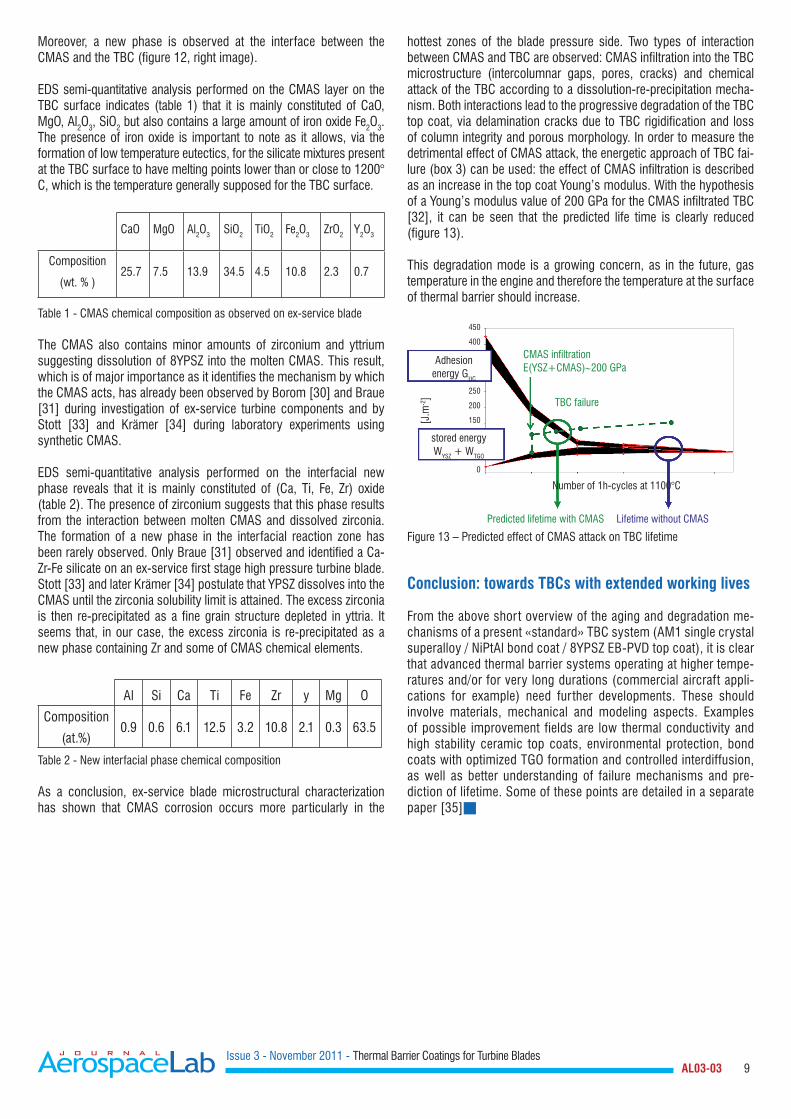
hottest zones of the blade pressure side. Two types of interaction between CMAS and TBC are observed: CMAS infiltration into the TBC microstructure (intercolumnar gaps, pores, cracks) and chemical attack of the TBC according to a dissolution-re-precipitation mecha-nism. Both interactions lead to the progressive degradation of the TBC top coat, via delamination cracks due to TBC rigidification and loss of column integrity and porous morphology. In order to measure the detrimental effect of CMAS attack, the energetic approach of TBC fai-lure (box 3) can be used: the effect of CMAS infiltration is described as an increase in the top coat Young’s modulus. With the hypothesis of a Young’s modulus value of 200 GPa for the CMAS infiltrated TBC [32], it can be seen that the predicted life time is clearly reduced (figure 13).
This degradation mode is a growing concern, as in the future, gas temperature in the engine and therefore the temperature at the surface of thermal barrier should increase.
Figure 13 – Predicted effect of CMAS attack on TBC lifetime
Conclusion: towards TBCs with extended working lives
From the above shor t overview of the aging and degradation me-chanisms of a present «standard» TBC system (AM1 single crystal superalloy / NiPtAl bond coat / 8YPSZ EB-PVD top coat), it is clear that advanced thermal barrier systems operating at higher tempe-ratures and/or for very long durations (commercial aircraft appli-cations for example) need fur ther developments. These should involve materials, mechanical and modeling aspects. Examples of possible improvement fields are low thermal conductivity and high stability ceramic top coats, environmental protection, bond coats with optimized TGO formation and controlled interdiffusion, as well as better understanding of failure mechanisms and pre-diction of lifetime. Some of these points are detailed in a separate paper [35]
CaO MgO Al2O3 SiO2 TiO2 Fe2O3 ZrO2 Y2O3
Composition
(wt. % )25.7 7.5 13.9 34.5 4.5 10.8 2.3 0.7
Al Si Ca Ti Fe Zr y Mg O
Composition
(at.%)0.9 0.6 6.1 12.5 3.2 10.8 2.1 0.3 63.5
Adhesionenergy G
IIC
CMAS infiltrationE(YSZ+CMAS)∼200 GPa
Number of 1h-cycles at 1100°C
450
400
stored energyWYSZ + WTGO
[J.m
-2]
250
200
150
0
TBC failure
Predicted lifetime with CMAS Lifetime without CMAS

Issue 3 - November 2011 - Thermal Barrier Coatings for Turbine Blades AL03-03 10
Acknowledgements
The French Ministry of Defense and Snecma are gratefully acknowledged for financial support and provision of coupons and ex-service blades.
References
[1] A.G. EVANS, D.R. MUMM, J.W. HUTCHINSON, G.H. MEIER, F.S. PETTIT – Mechanisms controlling the durability of thermal barrier coatings. Progr. Mater. Sci., 46 (2001) 505-553[2] S. BOSE - High temperature coatings. Elsevier (2007)[3] P. CARON, O. LAVIGNE - Recent Studies at Onera on Superalloys for Single Crystal Turbine Blades. Aerospace Lab issue 3 November 2011[4] V. LUGHI, V.K. TOLPYGO, D.R. CLARKE - Microstructural aspects of the sintering of thermal barrier coatings. Mater. Sci. Eng. A, 368 (2004) 212-221[5] A. AZZOPARDI, R. MÉVREL, B. SAINT-RAMOND, E. OLSON, K. STILLER - Influence of ageing on structure and thermal conductivity of Y-PSZ and Y-FSZ EB-PVD coatings. Surf. Coat. Technol., 177-178 (2004) 131-139[6] R.G. HUTCHINSON, N.A. FLECK, A.C.F. COCKS – A sintering model for thermal barrier coatings. Acta Mater., 54 (2006) 1297-1306[7] U. SCHULZ - Phase transformation in EB-PVD yttria partially stabilized zirconia thermal barrier coatings during annealing. J. Am. Ceram. Soc., 83 (2000) 904-910[8] J.F. BISSON, D. FOURNIER, M. POULAIN, O. LAVIGNE, R. MÉVREL - Thermal conductivity of yttria-zirconia single crystals determined with spatially resolved infrared thermography. J. Am. Ceram. Soc., 71 (2000) 255-260[9] J.G. SMEGGIL, A.W. FUNKENBUSH, N.S. BORNSTEIN - A relationship between indigenous impurity elements and protective oxide scale adherence characteristics. Metall. Mater. Trans. A, 7 (1986) 923-932[10] E. J. L. SMIALEK - Effect of sulfur removal on Al2O3 scale adhesion. Metal. Trans. A, 22 (1991) 739- 752[11] L. RIVOALAND, V. MAURICE , P. JOSSO, M.-P. BACOS, P. MARCUS- The effect of sulfur segregation on the adherence of the thermally grown oxide on NiAl. I: The oxidation behavior at 900°C of standard, desulfurized or sulfur-doped NiAl(001) single-crystal. Oxidation Metals, 60 (2003) 137-157[12] L. RIVOALAND, V. MAURICE , P. JOSSO, M.-P. BACOS, P. MARCUS - The effect of sulfur segregation on the adherence of the thermally grown oxide on NiAl. II: Sulfur segregation on the metallic surface of NiAl(001) single-crystals and at NiAl(001)/Al2O3 interfaces. Oxidation Metals, 60 (2003) 159-178[13] A. HAYNES, B. A. PINT, K. L. MORE, Y. ZHANG, I. G. WRIGHT - Influence of Sulfur, Platinum, and Hafnium on the Oxidation Behavior of CVD NiAl Bond Coatings. Oxidation Metals, 58 (2002) 513-544[14] B. A. PINT - Experimental observations in support of the dynamic-segregation theory to explain the reactive-element effect. Oxidation Metals, 45 (1996) 1-37[15] Y. CADORET, D. MONCEAU, M.-P. BACOS, P. JOSSO, V. MAURICE, P. MARCUS - Effect of platinum on the growth rate of the oxide scale formed on cast nickel aluminide intermetallic alloys. Oxidation Metals, 64 (2005) 185-205[16] P. Y. HOU, K. F. MCCARTY - Surface and interface segregation in -NiAl with and without Pt addition. Scripta Mat., 54 (2006) 937-941[17] R. BOUCHET, R. MÉVREL - Influence of platinum and palladium on diffusion in -NiAl phase. Defect Diffusion Forum, 237-240 (2005) 238-243[18] I.T. SPITZBERG, D.R. MUMM, A.G. EVANS - On the failure mechanisms of thermal barrier coatings with diffusion aluminide bond coatings. Mat. Sci. Eng., A 394 (2005) 176-191[19] P.-Y. THÉRY, M. POULAIN, M. DUPEUX, M. BRACCINI - Adhesion energy of a YPSZ EB-PVD layer in two thermal barrier coating systems. Surf. Coat. Technol., 202 (2007) 648-652[20] P.-Y. THÉRY, M. POULAIN, M. DUPEUX, M. BRACCINI - Spallation of two thermal barrier coating systems: experimental study of adhesion and energetic approach to lifetime during cyclic oxidation. J. Mater. Sci., 44 (2009) 1726-1733[21] V.K. TOLPYGO, D.R. CLARKE - Temperature and cycle-time dependence of rumpling in platinum-modified aluminide coatings. Scripta Mat., 57 (2007) 563-566[22] A. VILLEMIANE, B. PASSILLY, P. KANOUTÉ, R. KOUITAT, R. MÉVREL - Determination of mechanical properties of aluminide bondcoat materials by high temperature instrumented microindentation. Int. Conf. Metallurgical Coatings Thin Films, San Diego, USA (2008)[23] D.S. BALINT, J.W. HUTCHINSON - An analytical model of rumpling in thermal barrier coatings. J. Mechanics Phys. Solids, 53 (2005) 949-973[24] K. VAIDYANATHAN, E.H. JORDAN, M. GELL - Surface geometry and strain energy effects in the failure of a (Ni,Pt)Al/EB-PVD thermal barrier coating. Acta Mater., 52 (2004) 1107-1115[25] X. ZHAO, X. WANG, P. XIAO - Sintering and failure behaviour of EB-PVD thermal barrier coating after isothermal treatment. Surf. Coat. Technol., 200 (2006) 5946-5955[26] R.G. HUTCHINSON, J.W. HUTCHINSON – Lifetime assessment for thermal barrier coatings: tests for measuring mixed mode delamination toughness. J. Am. Ceram. Soc., 94 (2011) S85-S95[27] D.R. CLARKE, R.J. CHRISTENSEN, V. TOLPYGO - The evolution of oxidation stresses in zirconia thermal barrier coated superalloy leading to spalling failure. Surf. Coat. Technol., 94-95 (1997) 89-93[28] J.W. HUTCHINSON, Z. SUO - Mixed mode cracking in layered materials. Adv. Appl. Mech., 29 (1992) 63-191[29] J. L. SMIALEK, F.A. ARCHER, R.G. GARLICK - The chemistry of Saudi Arabian sand: A deposition problem on helicopter turbine a airfoils. 3rd Intern. SAMPE Metals Conf. (1992) pp. M63-M77 [30] M.P. BOROM, C.A. JOHNSON, L.A. PELUSO - Role of environmental deposits and operating surface temperature in spallation of air plasma sprayed thermal barrier coatings. Surf. Coat. Technol., 86-87 (1996) 116-126[31] W. BRAUE - Environmental stability of the YSZ layer and the YSZ/TGO interface of an in-service EB-PVD coated high-pressure turbine blade. J. Mater. Sci., 44 (2009) 1664-1675[32] C. MERCER, S. FAULHABER, A.G. EVANS, R. DAROLIA - A delamination mechanism for thermal barrier coatings subject to calcium-magnesium-alu-mino-silicate (CMAS) infiltration. Acta Mater., 53 (2005) 1029-1039[33] F.H. STOTT, D.J. DE WET, R. TAYLOR - Degradation of thermal barrier coatings at very high temperatures. MRS Bull. 19 (1994) 46-49

Issue 3 - November 2011 - Thermal Barrier Coatings for Turbine Blades AL03-03 11
AUTHORS
Marie-Pierre Bacos graduated from the Ecole Nationale Supé-rieure de Chimie in Paris (1981) and received a PhD degree in Applied Chemistry from University Paris VI (1983). She joined Onera in 1983 where she has been involved in oxidation and corrosion mechanisms and in the development of innovating coatings and brazing technologies. She is the Head of the Ma-
terials and Architecture Research Unit at Onera Châtillon.
Dr. Jean-Marc Dorvaux joined the Material Department of Onera as a research scientist in thermal physics. His activities cover both the experimental development of testing and the modelling of heat transfer in materials in harsh environments.
Odile Lavigne graduated as a physicist engineer from the Ecole Supérieure de Physique et Chimie Industrielles in Paris and obtained a PhD degree in Material Science from the Uni-versity of Paris VI. She joined Onera in 1986, where she was successively involved in developing stealth systems and high temperature composite materials for space applications. For
the past fifteen years she has been working as a senior scientist on thermal barrier systems for gas turbine engines.
Dr. Rémy Mévrel has a long experience in the field of high temperature protective coatings. His activities combine experi-mental and theoretical studies, in relation with both academic scientists and industrial partners. He introduced research acti-vities on thermal barrier coatings at Onera in the early 80s and has become rapidly a world known expert in this field.
[34] S. KRÄMER, J. YANG, C.A. JOHNSON, C.G. LEVI - Thermochemical Interaction of thermal barrier coatings with molten CaO-MgO-Al2O3-SiO2 (CMAS) deposits. J. Am. Ceram. Soc., 89 (2006) 3167-3175 [35] M.-P. BACOS, J.-M. DORVAUX, S. LANDAIS, O. LAVIGNE, R. MÉVREL, M. POULAIN, C. RIO, M.-H. VIDAL-SÉTIF - 10 Years-Activities at Onera on Advanced Thermal Barrier Coatings. Aerospace Lab issue 3 November 2011
Acronyms
TBC (Thermal Barrier Coating)YPSZ (Yttria Partially Stabilized Zirconia)EB-PVD (Electron Beam-Physical Vapor Deposition)TGO (Thermally Grown Oxide)CMAS (Calcium-Magnesium-Alumino-Silicates)EDS (Energy Dispersive Spectroscopy
Martine Poulain has been working at Onera since 1979, initially in the «Materials» department. She was involved in the develop-ment of protective coatings and she received her PhD degree from the University of Paris XI in 1999, on the topic of thermal insulation capabilities of TBCs. Her present research themes in the Metallic Materials and Structure department focus on the
damage and life modeling of TBCs, and the coating by design approach.
Catherine Rio graduated from the Institut Universitaire de Tech-nologie of Paris XI. She has been working at Onera since 1982 as a specialist in physical measurements, metallography and microstructure characterization on a wide range of high tempe-rature materials and coatings.
Marie-Hélène Vidal-Sétif graduated as a chemical engineer from the Ecole Supérieure de Physique et Chimie Industrielles in Paris and obtained a PhD degree in Physical Chemistry from the University of Paris XI. She joined Onera in 1987, where she was successively involved in the development of metal matrix composites (MMC), corrosion behavior of MMC and aluminum
alloys. For the past 7 years she has been working as a senior scientist on thermal barrier systems for gas turbine engines.