
Stereo Vision ECE 847: Digital Image Processing Stan Birchfield Clemson University.

Off-board processing of Stereo Vision images for
Obstacle Avoidance on a Flapping Wing MAV
S. Tijmons∗, G.C.H.E. de Croon, B.D.W. Remes, C. De Wagter,
R. Ruijsink, E. van Kampen and Q.P.Chu
Delft University of Technology, Delft, The Netherlands
December 11, 2014
Abstract
One of the focuses of Unmanned Air Vehicle research is to developinsect-scale vehicles, which can operate in environments inaccessible tohumans. For many applications it will be a key requirement that thesevehicles can operate fully autonomously. This implies that the vehicleshave the capability to avoid obstacles. Research on this task for Flap-ping Wing Micro Air Vehicles (MAVs) has been limited to single cameratechniques such as optic flow calculation and appearance variation extrac-tion. In this paper the first experiments are described where stereo visiononboard a light weight Flapping Wing MAV with off-board processing istested for the purpose of obstacle avoidance. An advantage of stereo visionover single camera techniques is that it provides distance measurementsinstantly. Furthermore Flapping wing MAVs will play an important rolein future research on miniaturizing MAVs. The research described in thispaper demonstrates the successful implementation of a stereo vision sys-tem with off-board processing on the 21-gram DelFly II for autonomousobstacle avoidance.
1 Introduction
Autonomous flight of Micro Air Vehicles (MAVs) concerns many aspects of guid-ance, navigation and control which are main areas of interest within aerospaceresearch. Therefore a fair amount of studies has been conducted with actualMAV platforms dealing with advanced methods in these areas. However, manyof these studies involve relatively heavy platforms, with a weight typically largerthan 500 grams. This allows the usage of heavy and often energy-consuming
∗All authors are with the Micro Air Vehicle laboratory of the Faculty of Aerospace
Engineering, Delft University of Technology, 2629 HS Delft, The Netherlands. Contact:
[email protected], [email protected]
1

sensors such as radars and laser scanners which provide long range and mil-limeter precision information on the environment (Griffiths et al.[1]). Theseexamples form a large contrast with previous studies concerning light weightFlapping Wing MAVs (FWMAVs) where the sensor payload weight is limitedto only a few grams. Duhamel et al.[2] describes experiments with the RoboBee,a 101-milligram FWMAV equipped with an optic flow sensor. Using externalpower and off-board processing, the altitude is controlled by pointing the sensorto a highly-textured screen. Baek et al.[3] demonstrated a 13-gram FWMAVequipped with an infrared sensor to track a specific infrared target point. Pro-cessing is performed onboard, including 3-axis gyroscope feedback for attitudecontrol. Over 20 trials the vehicle was able to fly to the target with a successrate of 85%. Garcia Bermudez et al.[4] describes experiments on a 7-gram FW-MAV equipped with a camera that stores heavily downsampled images during ashort period of a flight. The images are uploaded to a pc afterwards to performoptic flow computations. This way it was demonstrated that there is a largecoupling between the body motion due to flapping and the measured optic flow.
Several experiments with the DelFly II regarding autonomous tasks havebeen performed as well. De Croon et al.[5](2009) describe experiments whereonboard camera images are sent to a ground station that performs height cal-culation and path following. Based on these measurements control signals aredetermined and sent to the vehicle. Also obstacle avoidance experiments havebeen performed using this setup, as described by De Croon et al.[6](2012a) andDe Croon et al.[7](2012b). The ground station performed a combination of opticflow computation and appearance variation measurements. Appearance varia-tion was proposed as a new image cue that bases a proximity estimate on thevariation in texture in the image and was demonstrated as a useful addition tooptic flow measurements for the task of obstacle avoidance.
The experiments with the DelFly II showed that the use of optic flow mea-surements while performing off-board processing has a limited success. Themain reason for this is the relatively low frame rate (30 FPS) of the video streamwhich results in significant image distortions and large changes in camera at-titude between frames (due to the flapping motion). Compensation for theseeffects is theoretically possible using 3-axis gyroscope feedback. This would re-quire all processing to be done onboard, but the available processing power wasnot sufficient at that time. Also image noise due to analog transmission has anegative influence on optic flow measurement accuracy.
In this paper stereo vision is proposed as an alternative to optic flow toget around these issues. While optic flow requires a sequence of images fromdifferent moments in time, stereo vision can perform distance measurementsbased on a single pair of left and right images. The frame rate of the transmittedcamera images does not play a role in this case, and obstacle information isobtained instantly.
In Section 2 the stereo vision method used in this study is discussed. Section3 describes the DelFly II and the system overview used during experiments.The performance of the used system is reviewed in Section 4. The obstacleavoidance strategy implemented in this study as well as results from experiments
2

are discussed in Section 5. The Conclusions are drawn in Section 6.
2 Stereo Vision method
Stereo vision is a technique to extract depth information about the environmentfrom two or images taken from different and known positions. By matching cor-responding features in these images, the shift in pixel position of these featuresis determined, which is called the disparity. If the camera characteristics andpositions are known, the disparity value is used to compute the metric positionof the feature relative to the camera. By matching all image features, a dense3D reconstruction of the environment can be made for further purposes such asnavigation.
Stereo vision is still a widely studied area of image processing and this has ledto a large variety of methods. A recurring aspect of stereo vision is the tradeoffbetween the quality of the disparity maps and the computational efficiency ofthe method. These conflicting requirements are the source of a wide range ofproposed methods. Good overviews of stereo vision methods are presented byScharstein&Szeliski[8] and Tombari et al.[?]. In this section it is discussed inwhich groups the methods can be divided and how these relate to the purposeof this study.
In this study stereo vision will be used as a source for obstacle detection ona flying platform. Therefore the main requirement for the stereo vision methodis that it has real-time performance. Real-time is defined here as close to theactual frame rate of the video stream, which is 25 FPS in this study. Thisrequirement can be met in two ways. The first way is to use special hardwarededicated to perform optimal for certain image processing routines. In litera-ture it is very common to use implementations on Graphical Processing Units,Field Programmable Gate Arrays, Application-Specific Integrated Circuits andDigital Signal Processors. These types of implementations are in general notapplicable to systems with a very small weight and limited power supply. Sincethe aim of this study is to obtain autonomous behavior of an MAV, it is chosento focus on implementations that have the potential of being used onboard infuture studies. Therefore the chosen stereo vision system should perform inreal-time on a normal CPU via another approach: by using extremely efficientalgorithms. In other words, a stereo vision method should be used that forms agood tradeoff between accuracy and computational complexity.
Stereo vision algorithms can be roughly divided in three different groups.The first group is formed by the Local methods, where image regions withlimited size are tried to be matched based on a cost function. The methods are ingeneral very efficient but lack quality when the variation of texture in the stereoimages is low. On the other side there is the group of Global methods, that tryto create a disparity map that optimizes a cost function for the complete image.This requires in general a large amount of processing steps and also puts a highdemand in required memory. These methods mainly focus on quality only, whilereal-time performance is neglected. The group of Semi-Global methods forms
3

a bridge between the other two groups. These methods do use an optimizationstrategy but in a limited way. For example, some methods optimize the costfunction only for a single image line. This group of methods contains the mostefficient stereo vision algorithms and was therefore further studied.
The best candidate for implementation on our FWMAV system was found tobe the Semi-Global Matching method proposed by Hirschmuller[9]. The methodperforms optimization along different directions: horizontally, vertically anddiagonally. According to literature Semi-Global Matching represents a goodtrade-off between computational efficiency and performance (Banz et al.[10],Gehrig&Rabe[11], Chen&Chen[12]).
An OpenCV1 implementation of this method was used in this study. Thecamera images are subsampled to 160×108 pixels to obtain a processing rateof 25 FPS. To illustrate the efficiency of the algorithm a comparison is madewith two other stereo vision methods as illustrated in Figure 1. An exampleimage from the stereo camera used in this study is used in this comparison. Thefigure shows the disparity result from three different methods: Block Matching, Dynamic Programming (based on Birchfield&Tomasi[13]), and Semi-GlobalMatching.
Block Matching is a method that does not perform optimization, but purelytries to match image windows. The matching cost for different disparity can-didates is compared, and the disparity resulting in the lowest cost is chosen.Dynamic Programming is a method that performs optimization in 1D, alongthe image line only. These two methods are less computationally demandingcompared to the Semi-Global method.
The top-right image of Figure 1 shows the result from the Block Matchingmethod. The bright pixels indicate that image features are close by, dark pixelsindicate that the features are further away. Black means that no good matchcould be made. This example illustrates that local methods perform very badfor image regions with a small variation in texture. Only the image parts thatcontain clear lines are matched correctly.
The bottom-left image of Figure 1 shows that the 1D optimization strategyof the Dynamic Programming method is not sufficient in many cases and maylead to very bad disparity estimates. This is due to the fact that wrong disparityestimates at one point along the optimization line have a negative effect on theother estimates along that line. This results in the striping effect that is visiblein the disparity image.
The bottom-right image of Figure 1 shows the result from Semi-GlobalMatching. It is clear that this method outperforms the other two examplemethods significantly. The amount of pixels that has been matched is larger,and the structure of the background is much better indicated by this method.
1www.opencv.org
4
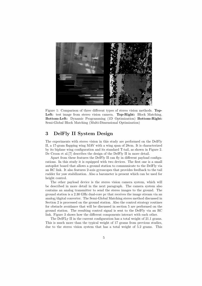
Figure 1: Comparison of three different types of stereo vision methods. Top-
Left: test image from stereo vision camera. Top-Right: Block Matching.Bottom-Left: Dynamic Programming (1D Optimization) Bottom-Right:
Semi-Global Block Matching (Multi-Dimensional Optimization)
3 DelFly II System Design
The experiments with stereo vision in this study are performed on the DelFlyII, a 17-gram flapping wing MAV with a wing span of 28cm. It is characterizedby its biplane wing configuration and its standard T-tail, as shown in Figure 2.De Croon et al.[7] describes the design of the DelFly II in more detail.
Apart from these features the DelFly II can fly in different payload configu-rations. In this study it is equipped with two devices. The first one is a smallautopilot board that allows a ground station to communicate to the DelFly viaan RC link. It also features 2-axis gyroscopes that provides feedback to the tailrudder for yaw stabilization. Also a barometer is present which can be used forheight control.
The other payload device is the stereo vision camera system, which willbe described in more detail in the next paragraph. The camera system alsocontains an analog transmitter to send the stereo images to the ground. Theground station is a 2.30 GHz dual-core pc that receives the image stream via ananalog/digital converter. The Semi-Global Matching stereo method discussed inSection 2 is processed on the ground station. Also the control strategy routinesfor obstacle avoidance that will be discussed in section 5 are performed on theground station. The resulting control signal is sent to the DelFly via an RClink. Figure 3 shows how the different components interact with each other.
The DelFLy II in the current configuration has a total weight of 21.1 grams.This is much more than the typical weight of 17 grams from previous studies,due to the stereo vision system that has a total weight of 5.2 grams. This
5
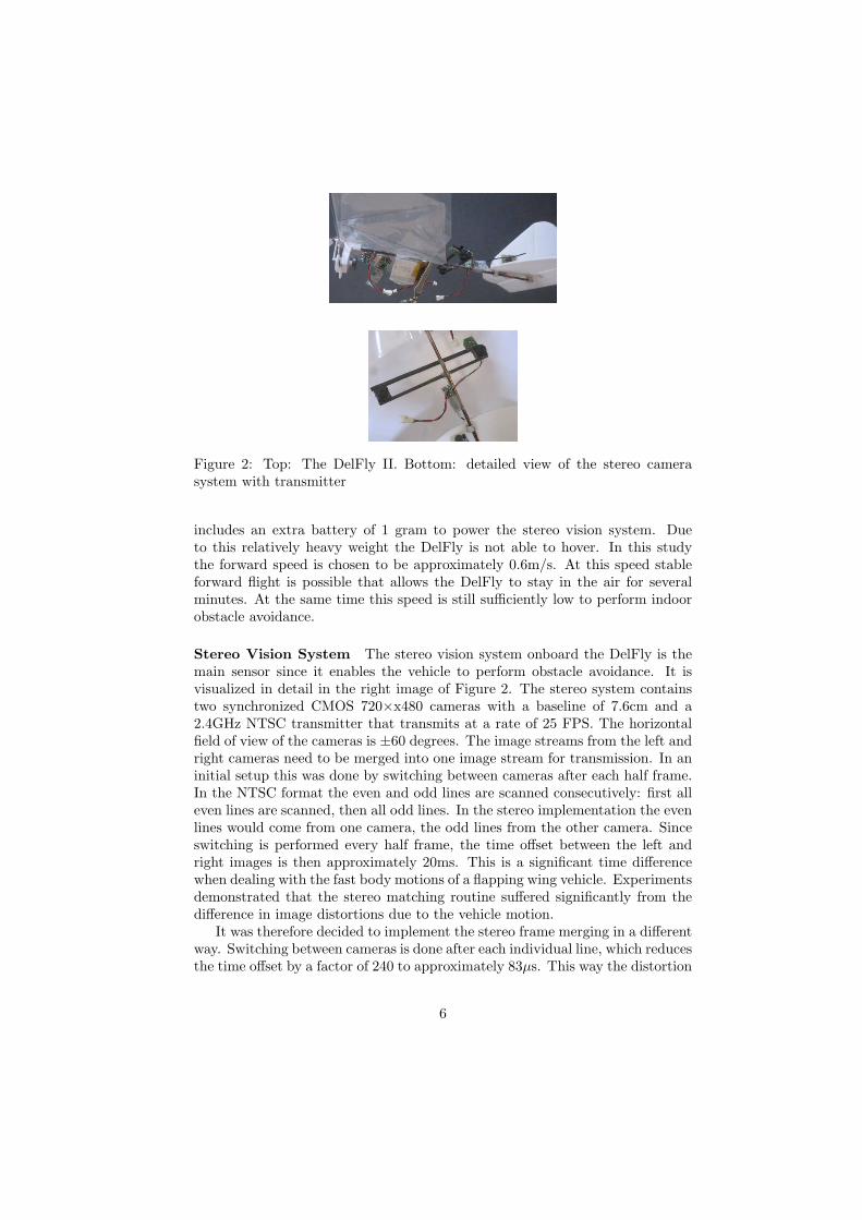
Figure 2: Top: The DelFly II. Bottom: detailed view of the stereo camerasystem with transmitter
includes an extra battery of 1 gram to power the stereo vision system. Dueto this relatively heavy weight the DelFly is not able to hover. In this studythe forward speed is chosen to be approximately 0.6m/s. At this speed stableforward flight is possible that allows the DelFly to stay in the air for severalminutes. At the same time this speed is still sufficiently low to perform indoorobstacle avoidance.
Stereo Vision System The stereo vision system onboard the DelFly is themain sensor since it enables the vehicle to perform obstacle avoidance. It isvisualized in detail in the right image of Figure 2. The stereo system containstwo synchronized CMOS 720×x480 cameras with a baseline of 7.6cm and a2.4GHz NTSC transmitter that transmits at a rate of 25 FPS. The horizontalfield of view of the cameras is ±60 degrees. The image streams from the left andright cameras need to be merged into one image stream for transmission. In aninitial setup this was done by switching between cameras after each half frame.In the NTSC format the even and odd lines are scanned consecutively: first alleven lines are scanned, then all odd lines. In the stereo implementation the evenlines would come from one camera, the odd lines from the other camera. Sinceswitching is performed every half frame, the time offset between the left andright images is then approximately 20ms. This is a significant time differencewhen dealing with the fast body motions of a flapping wing vehicle. Experimentsdemonstrated that the stereo matching routine suffered significantly from thedifference in image distortions due to the vehicle motion.
It was therefore decided to implement the stereo frame merging in a differentway. Switching between cameras is done after each individual line, which reducesthe time offset by a factor of 240 to approximately 83µs. This way the distortion
6

Figure 3: Diagram of the interaction between all system components
of the images themselves is not solved, but the distortion between the left andright frames is almost the same.
The effect of this change was measured by performing a small test. Thedisparity map as obtained by the ground station was compared for the twoimplementations under two conditions. During the first condition, the camerais pointed at a static scene. During the second condition, the scene observed bythe camera is moving randomly left and right to imitate camera motion.
The results from this test are shown in Figure 4. The top plot shows themeasurements using the initial implementation. After 135 frames, the observedscene starts to move. The effect on the disparity measurements is clearly signif-icant. The left and right motion of the scene can be observed in this data by thesinusoidal motion. The bottom plot shows that for the chosen implementationthis effect is reduced to additional noise only.
4 Stereo Vision System Performance
The performance of the stereo vision system as implemented on the DelFly II inthis study is evaluated by two experiments. The first experiments measures theaccuracy of the stereo vision system in measuring the distance to obstacles in thecase the camera and the scene are static. This was done by pointing the stereovision camera to a screen with a large chess board pattern. The distance basedon the disparity map computed at the ground station is averaged over 1100frames and this is repeated at different distances to the screen. Figure 5 showsthe result from this test. The left plot shows the mean and standard deviation
7

0 50 100 150 200 25020
22
24
26
disp
arity
0 50 100 150 200 25020
22
24
26
frame
disp
arity
std.dev. 0.42878 std.dev. 1.1915
std.dev. 0.2228 std.dev. 0.44618
Figure 4: Comparison between the camera reading methods. Top initial methodBottom implemented method. During the first 135 frames there is no motion(dash-dotted lines), further on there is a relative motion between the cameraand the chessboard (solid lines).
for 7 measurement points up to a distance of 5m. The right plot shows the samemeasurements, as well as another measurement at 6m. From these results it canbe concluded that the accuracy of the distance measurements up to 5m has anaverage error of less than 50cm. This is regarded as sufficient for the task ofobstacle avoidance. Note that at smaller distances the measurement accuracyis even higher.
The experiment has been repeated in the form of a flight test with theDelFly. This way the effect of the body motion of the vehicle on the distancemeasurements is taken into account. The DelFly was flying in the direction ofthe same screen as used in the previous experiment, starting at a distance of4.5m. A ground truth distance was obtained by tracking the position of theDelFly with two external cameras.
The results are presented in Figure 6. The left plot shows several mea-surement points indicated as outliers as they are results from corrupted frames(frames where some synchronization error of the cameras resulted in a swap ofthe left and right camera). The results in the right plot show that the accuracyduring flight is fairly close to that of the static case. The increase in standarddeviation due to camera motion was also noticed in Figure 4 in the previoussection. Figure 6 shows that the flight test measurements follow the same trendin standard deviation as for the static case, including the dimple at 3m. Fordistances larger than 4m the accuracy seems to increase significantly. This ispartly caused by an initial offset in the flight direction of the DelFly during the
8

0 100 200 300 400 500 600−30
−20
−10
0
10
20
30
Actual distance [cm]
Mea
n er
rror
and
std
. dev
. of m
easu
red
dist
ance
[cm
]
0 200 400 600 800−140
−120
−100
−80
−60
−40
−20
0
20
40
Actual distance [cm]
Mea
n er
rror
and
std
. dev
. of m
easu
red
dist
ance
[cm
]
Figure 5: Distance measurement accuracy for the static case. The left plot is adetailed version of the right plot.
first second of the test. This can be seen in the left plot.
5 Obstacle Avoidance
The main focus of this study is to test the stereo vision system implementationas described in the previous sections for the task of obstacle avoidance. A fewpreliminary tests were performed first to determine requirements for a robustavoidance strategy.
A straight forward approach is a simple reactive controller that checks ifthere are obstacles at a distance below a predefined threshold. If this is thecase, the vehicle will turn left if the obstacle was detected on the right side ofthe image, and vice versa. This strategy proved to be not robust since situationscan occur where this will lead to wrong turn decisions. If the vehicle flies in thedirection of a corner it will not turn away from it. Furthermore, the camerashave a limited field of view of 60 degrees. By using this reactive approach, anavoidance maneuver can steer the vehicle in the direction of an obstacle thatwas out of sight.
The main reason for these issues is the limitation of the DelFly in that it canonly fly with a minimal forward speed. A simple test was performed where theDelFly would use its elevator to pitch up 90 degrees. This reduces the forwardspeed to hover condition, such that the DelFly can turn around without hittingobstacles on the side. This approach proved to be successful. However, theDelFly will descent quickly in these cases because it does not provide sufficientthrust while hovering.
Therefore a new strategy for obstacle avoidance was tested that takes intoaccount these limitations and requirements. In this strategy it is assumed thatthe DelFly is flying at a constant forward speed. As mentioned earlier, the
9

10 11 12 13 14 15 16 17 18−700
−600
−500
−400
−300
−200
−100
0
Time [s]
Dis
tanc
e to
wal
l [cm
]
0 50 100 150 200 250 300 350 400 4500
5
10
15
20
25
30
35
40
45
50
Distance to wall [cm]
abso
lute
mea
sure
men
t err
or [c
m]
Distance tracked by external camerasDistance estimation by stereo camerasDistance estimation by stereo cameras (outliers)
absolute errorsstd.dev. from static teststd.dev. from data points
Figure 6: Distance measurement accuracy for the flight test. The left plot showsthe actual distance and estimated distance over time. The right plot shows theestimation error with reference to the actual distance.
forward speed of the DelFly is controlled by an elevator, which is part of thetail. In Figure 2 the DelFly is shown while having a small pitch angle. It can alsobe seen that the elevator surface is deflected downwards. The DelFly would flywith fast forward speed in this condition. For the slow forward flight conditionthat is needed for obstacle avoidance, the elevator is deflected up, which resultsin high pitch angles of around 80 degrees. The speed of the DelFly is fairlyconstant in this case, but any type of wind disturbance has a significant effecton the speed. For this reason tests were performed in a closed room.
Based on the assumption of a constant forward speed, a safety region in frontof the DelFly is defined. It is illustrated in the left plot of Figure 7. The safetyregion is defined in such a way that the DelFly can safely perform an avoidancemaneuver within the boundaries of this area. If the system continuously assuresthat there is no obstacle within this region, the DelFly does not need to avoidanything. If at some point an obstacle is detected at the boundary of thesafety area, it is assured that if the DelFly will perform its avoidance maneuveras defined by the safety region, it will have a guaranteed collision-free escaperoute.
The safety region as shown in Figure 7 is composed in the following way.Since it is not known beforehand in which direction the DelFly will continueafter an avoidance maneuver, it is required that the vehicle can make a 360degrees turn within the safety region. Due to the minimum forward speed of0.6m/s, the radius of this turn was measured to be 50cm. On top of that thewing span of the DelFly (28cm) needs to be taken into account, as well as theuncertainties of the distance estimates that were evaluated in Section 4. At adistance of 3m, an uncercainty of 20cm is regarded as a safe choice. The total
10
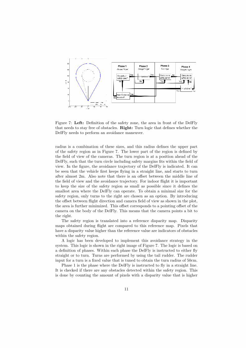
Figure 7: Left: Definition of the safety zone, the area in front of the DelFlythat needs to stay free of obstacles. Right: Turn logic that defines whether theDelFly needs to perform an avoidance maneuver.
radius is a combination of these sizes, and this radius defines the upper partof the safety region as in Figure 7. The lower part of the region is defined bythe field of view of the cameras. The turn region is at a position ahead of theDelFly, such that the turn circle including safety margins fits within the field ofview. In the figure, the avoidance trajectory of the DelFly is indicated. It canbe seen that the vehicle first keeps flying in a straight line, and starts to turnafter almost 2m. Also note that there is an offset between the middle line ofthe field of view and the avoidance trajectory. For indoor flight it is importantto keep the size of the safety region as small as possible since it defines thesmallest area where the DelFly can operate. To obtain a minimal size for thesafety region, only turns to the right are chosen as an option. By introducingthe offset between flight direction and camera field of view as shown in the plot,the area is further minimized. This offset corresponds to a pointing offset of thecamera on the body of the DelFly. This means that the camera points a bit tothe right.
The safety region is translated into a reference disparity map. Disparitymaps obtained during flight are compared to this reference map. Pixels thathave a disparity value higher than the reference value are indicators of obstacleswithin the safety region.
A logic has been developed to implement this avoidance strategy in thesystem. This logic is shown in the right image of Figure 7. The logic is based ona definition of phases. Within each phase the DelFly is instructed to either flystraight or to turn. Turns are performed by using the tail rudder. The rudderinput for a turn is a fixed value that is tuned to obtain the turn radius of 50cm.
Phase 1 is the phase where the DelFly is instructed to fly in a straight line.It is checked if there are any obstacles detected within the safety region. Thisis done by counting the amount of pixels with a disparity value that is higher
11

than that of the disparity map. If this exceeds a threshold of 250 pixels, thismeasurement is counted. If this happens more than ten times within a second, itis decided to go to Phase 2. This is a way of filtering bad or noisy measurements.
In Phase 2 the DelFly is flying the straight trajectory as indicated in thesafety region in Figure 7. The system waits until a certain time has passed togo to Phase 3. This time is based on the distance to the turn point and theassumed forward speed of the DelFly.
In Phase 3 the DelFly starts to turn by giving the predefined rudder input.At the same time it is checked again if the safety region contains obstacles ornot. As soon as the safety region is found to be clear (less than 200 pixels have ahigher disparity than the reference) the system switches to Phase 4 immediately.Since the DelFly is turning relatively fast, it is important to react quickly tomeasurements that indicate a safe direction of flight. Small time delays willresult in significant overshoots in heading.
In Phase 4 the DelFly is instructed to fly straight again. However, since anerror could have been made in Phase 3, it is checked again if the safety regionis still clear. If this is not the case, the DelFly will go back to Phase 3 andcontinue its turn. If this does not occur within one second, the system returnsto Phase 1.
Furthermore, in Phase 1 it is always checked if there are obstacles at a reallyshort distance of less than 1m. If this is the case, it is important to react tothat situation immediately, even if it is not known if there are obstacles on theside. The system will go to Phase 3 if more than 500 pixels indicate an objectat this short range.
Experiment The obstacle avoidance routine was tested in a room of 8.2×7.3meter. This room was not adapted for the experiment. It contains both whitewalls with poor texture as well as walls with cabinets on the sides. Duringthe best flight trial, the DelFly flew autonomously for 72 seconds. No operatorinterventions were made during this period. The operator decided to end theflight after the 72 seconds by catching the DelFly.
During the experiment the flight trajectory of the DelFly was tracked by twoexternal cameras. The result is shown in Figure 8. The colors in the trajectoryindicate the phases from the control logic. The numbers indicate the flighttime. Several remarks can be made on these results, and for this reason the fulltrajectory is discussed.
The tests starts at time=0, where the DelFly has just been turned away fromthe corner by the operator. From this point on, the operator did not controlthe DelFly anymore. During the next ten seconds the DelFly is in Phase 1and is supposed to fly straight. However, it can be observed that the flighttrajectory is far from a perfect straight line. This is mainly due to a ventilationsystem in the ceiling. After the first 10 seconds Phase 2 and 3 are initiatedconsecutively. Note that this part corresponds to the avoidance trajectory fromFigure 7. After this turn the DelFly flies to another wall (around time=20)which it avoids initially, but it needs to avoid it again a bit later because the
12

DelFly turns back to the wall again. This is the effect of the rudder control,which makes the DelFly unstable. Using the rudder for heading control is notideal, since a rudder input initiates a yawing motion that disturbs the roll angle(heading angle).
Three successful avoidance turns are shown between time=20 and time=50.At time=50, a situation is shown where the control logic decides to go fromPhase 3 to 4 while the DelFly is still flying in the direction of a wall. Aftera short moment the controller switches back to Phase 3 again and the turnis continued. This is caused by the poor texture of the wall, since the wall iscompletely white. This results in very uncertain measurements that often resultin measurements with high disparity values, but sometimes also very low values.
It can also be noted that in many cases the DelFly seems to keep turningfor a while even though it has already switched to Phase 4. In the first placethis is caused by a delay due to RC communication between ground station andthe DelFly. Furthermore the instability effects due to rudder inputs have theeffect that the DelFly takes a bit of time to recover from a turn. While therudder is back to the trim position, the DelFly still turns a bit more before itflies straight.
The test demonstrates that the DelFly is able to detect obstacles aheadof the vehicle using is stereo vision system and that this allows for successfulavoidance. The recorded flight time of 72 seconds is a major improvement tothe record of 30 seconds presented by De Croon et al.[7] using a DelFly incombination with optic flow.
13

0
10
20
30
40
50
60
70
72.4
phase 1
phase 2/3
phase 4
Figure 8: Flight track of the DelFly during the experiment. The numbersindicate the flight time, the colors represent the flight phases.
6 Conclusions
The study described in this paper has demonstrated that robust obstacle avoid-ance on a Flapping Wing MAV can be successfully realized by using stereovision cameras onboard. It was shown that the distance estimates obtained bystereo vision can be used as a cue to implement a robust avoidance strategy.This enables the FWMAV to avoid situations where it would get locked up.It was also shown that the severe body motions due to flapping do not have alarge influence on the distance measurements. This shows that stereo vision canoutperform optic flow techniques.
In this study stereo vision was implemented by using a ground station toperform the stereo vision processing. It is still a large step to go from off-boardto onboard processing. Nevertheless, this study proves the potential of usingstereo vision for the purpose of obstacle avoidance on a FWMAV. Future studieswill focus on onboard implementations of the whole system including processingand control loops.
14

References
[1] Griffiths, S., Curtis, J., Barber, B., McLain, T., and Beard, R., “Obstacleand terrain avoidance for miniature aerial vehicles,” Advances in UnmannedAerial Vehicles , 2007, pp. 213–244.
[2] Duhamel, P., Perez-Arancibia, N., Barrows, G., and Wood, R., “Altitudefeedback control of a flapping-wing microrobot using an on-board biologi-cally inspired optical flow sensor.” 2012, pp. 4228–4235.
[3] Baek, S., Bermudez, F. G., and Fearing, R., “Flight control for targetseeking by 13 gram ornithopter.” IEEE/RSJ Int Conf on Intelligent Robotsand Systems., 2011.
[4] Bermudez, F. G. and Fearing, R., “Optical flow on a flapping wing robot,”IROS 2009 , 2009, pp. 5027–5032.
[5] de Croon, G., de Clerq, K., Ruijsink, R., Remes, B., and de Wagter, C.,“Design, aerodynamics, and vision-based control of the DelFly,” Interna-tional Journal on Micro Air Vehicles , Vol. 1, No. 2, 2009, pp. 71 – 97.
[6] de Croon, G., de Weerdt, E., de Wagter, C., Remes, B., and Ruijsink, R.,“The appearance variation cue for obstacle avoidance,” IEEE Transactionson Robotics , Vol. 28, No. 2, 2012, pp. 529–534.
[7] de Croon, G., Groen, M., Wagter, C. D., Remes, B., Ruijsink, R., and vanOudheusden, B., “Design, Aerodynamics, and Autonomy of the DelFly,”Bioinspiration and Biomimetics , Vol. 7, No. 2, 2012.
[8] Scharstein, D. and Szeliski, R., “A taxonomy and evaluation of dense two-frame stereo correspondence algorithms,” International Journal of Com-puter Vision, Vol. 47, No. 1/2/3, 2002, pp. 7–42.
[9] Hirschmuller, H., “Accurate and efficient stereo processing by semi-globalmatching and mutual information,” Computer Vision and Pattern Recog-nitio (CVPR), Vol. 2, 2005, pp. 807–814.
[10] Banz, C., Hesselbarth, S., Flatt, H., Blume, H., and Pirsch, P., “Real-timestereo vision system using semi-global matching disparity estimation: archi-tecture and FPGA-implementation,” IEEE Conf. on Embedded ComputerSystems (SAMOS), 2010, pp. 93–101.
[11] Gehrig, S. and Rabe, C., “Real-time semi-global matching on theCPU,” IEEE Conf. on Computer Vision and Pattern Recognition Work-shop(CVPR), 2010, pp. 85–92.
[12] Chen, B. and Chen, H., “A realization of semi-global matching stereo algo-rithm on GPU for real-time application,” International Symposium on Mul-tispectral Image Processing and Pattern Recognition (MIPPR2011), 2011,pp. 80040W–80040W.
15

[13] Birchfield, S. and Tomasi, C., “Depth discontinuities by pixel-to-pixelstereo,” International Journal of Computer Vision, Vol. 35(3), 1999,pp. 269–293.
16


![IEEE TRANSACTIONS ON IMAGE PROCESSING 1 Pothole … · stereo vision, road surface geometry can be reconstructed with a three-millimeter accuracy [4], [12]. Additionally, stereo cam-eras](https://static.fdocuments.net/doc/165x107/6028629122ed7562c311770b/ieee-transactions-on-image-processing-1-pothole-stereo-vision-road-surface-geometry.jpg)