nXis - Well Integrity Inspection in Unconventional Gas Wells · 2016-08-25 · nXis - Well...
34
nXis - Well Integrity Inspection in Unconventional Gas Wells DE-FOA-0001076 Matthias Kasten, Ph.D. General Electric Company U.S. Department of Energy National Energy Technology Laboratory Mastering the Subsurface Through Technology, Innovation and Collaboration: Carbon Storage and Oil and Natural Gas Technologies Review Meeting August 16-18, 2016
Transcript of nXis - Well Integrity Inspection in Unconventional Gas Wells · 2016-08-25 · nXis - Well...

nXis - Well Integrity Inspection in
Unconventional Gas WellsDE-FOA-0001076
Matthias Kasten, Ph.D.
General Electric Company
U.S. Department of Energy
National Energy Technology Laboratory
Mastering the Subsurface Through Technology, Innovation and Collaboration:
Carbon Storage and Oil and Natural Gas Technologies Review Meeting
August 16-18, 2016

2
Presentation Outline
• Project Goals & Objectives
• Technical Status Neutron Modality
X(γ)-Ray Modality
Ultrasound Modality
Electromagnetic Modality
Multi-Modality Data Fusion
Test Pit Testing
• Accomplishments to Date
• Summary

3
Benefit to the Program
• Well integrity inspection for multi-casing gas wells to
enhance safety and environmental protection.
• Dual-particle imaging technique using neutron and X(γ)-
ray backscatter.
• The research project is developing a new dual-particle
imaging technique, combining neutron and X(γ)-ray
modalities, and algorithmically fusing this data with
information obtained from electromagnetic imaging to
obtain results which are intrinsically more accurate than
the simple union of individual modality results.

4
Project Overview: Goals and Objectives
• Measuring the integrity of multiple well casings and
cement annuli at intermediate-to-surface depths along
major ground water zones.
• Current imaging technologies cannot resolve multiple
annuli in the intermediate zone above 10,000 ft. where
there are 2 to 5 stacked casing/cement rings.
• Ultrasound-based techniques do not operate reliably in
gas filled wellbores.
• Electromagnetic tools are sensitive only to damages in
metallic structures. Internal pipe strings magnetically
shield external pipes to significantly reduce sensitivity.

5
Project Overview: Goals and Objectives

Technical Status
Neutron Modality
Neutron Backscatter Experimental Setup
Photographs of integrated neutron generatorprototype system (1-11/16” form factor).
Neutron Detector Assembly
Neutron Generator Stacked Defects
MCNP simulation input showing neutrongenerator, defects, and detector assembly.
Detector Assembly

Technical Status
Neutron Modality
Cement Air Defect HD PE Defect
Experimental Data
Detection Results:
• Clear distinction between cement (no
defect), air void, and high-density
polyethylene (HD PE) for 3’’ by 2.5’’ size
defect.
• Azimuthal defect detection.
Phantom with 3’’×2.5” diameter defects:cement (no defect), air void, and HD PE.
Ra
tio
of
De
tect
ors

Technical Status
Neutron Modality
Multi-Annulus Experimental Setup 8
Technical Status
X(γ)-Ray Modality
Top and side view of detector internal configuration
X(γ)-raybeam
Definition of Detectability:
A defect is deemed detectable if the threshold metric of
2σ is met (95% confidence).
Source:
X()-Ray source
Monte Carlo N-Particle (MCNP) Simulation:
Defect:
Air void defects with various diameters (e.g. ⅛’’)

Technical Status
X(γ)-Ray Modality MCNP: Air Void Detection in 2nd Casing
X(γ)-Ray Detector
1st Casing 2nd Casing
Cement
Air Void
Top & side view of detector configuration
1σ error bar
>2σ confidence
Energy (MeV)
Counts
No Void Air Void
X(γ)-Ray Detector
X(γ)-Ray Collimator X(γ)-Ray
Air Void

Technical Status
X(γ)-Ray Modality
MCNP Simulations: Air Void Detection in 2nd Casing
11

Technical Status
X(γ)-Ray Modality
Detection Results:
• Detection of ⅛’’ air void in 2nd metal casing and
cement annulus (from MCNP simulations).
• Defect detectability up to 3.5’’ past first casing
(from MCNP simulations).
• Azimuthal defect detection.
Backscatter rate vs. defect position for½’’ and ¼’’ blind hole (3mm depth, 50%).
Co
un
ts /
30
0 s
/ 4
.5 m
Ci
Horizontal Position (cm)
Steel PlateAir Void
Photograph of ¼” through hole steel-cement-steel void detection experiment.
PMT
Crystal
γ-Ray Source

Technical Status
X(γ)-Ray Modality
Multi-Annulus Experimental Lab Setup
Multi-Annulus X(γ)-Ray Detector
X(γ)-Ray Detector
X(γ)-Ray Source
1st, 2nd, and 3rd Casings

Technical Status
Ultrasound Modality
Low Frequency Air-Contact Experiments
Concrete phantom with air void defects
“Pitch-Catch” experimental setup
50 kHz
Detection of air void defects in concrete

Technical Status
Ultrasound ModalityElectro Magnetic Acoustic Transducer (EMAT) Testing
Photograph of laboratory setupVarious test setups used for EMAT evaluation
SH Wave Sensor Transmitter
SH Wave Sensor Receiver
Small signal variations for SH wave experiment!
15

Technical Status
Electromagnetic Modality
20 %
30 % 40 %
Production tube inspection with a 1.5” transceiver probe.External area material losses of 20%, 30%, and 40%.
Casing Eccentricity Measurements
Detection Results:
• Defect detectability (material loss) in 1st casing.
• Eccentricity detectability between 1st and 2nd casing.
• Azimuthal defect detection.

Technical Status
Electromagnetic Modality
Signal response for two coilsEccentricity measurements between 1st and 2nd casing
17
Signals from multiple coils allow for unique
identification of the pipe position/eccentricity.

Technical Status
Multi-Modality Data Fusion
Reshaping of simulated X(γ)-ray image to match electromagnetic defect image
Simulated material defect for X(γ)-ray data
18
Block diagram of multi-modality data fusion approach
X(γ)-ray
Technical Status
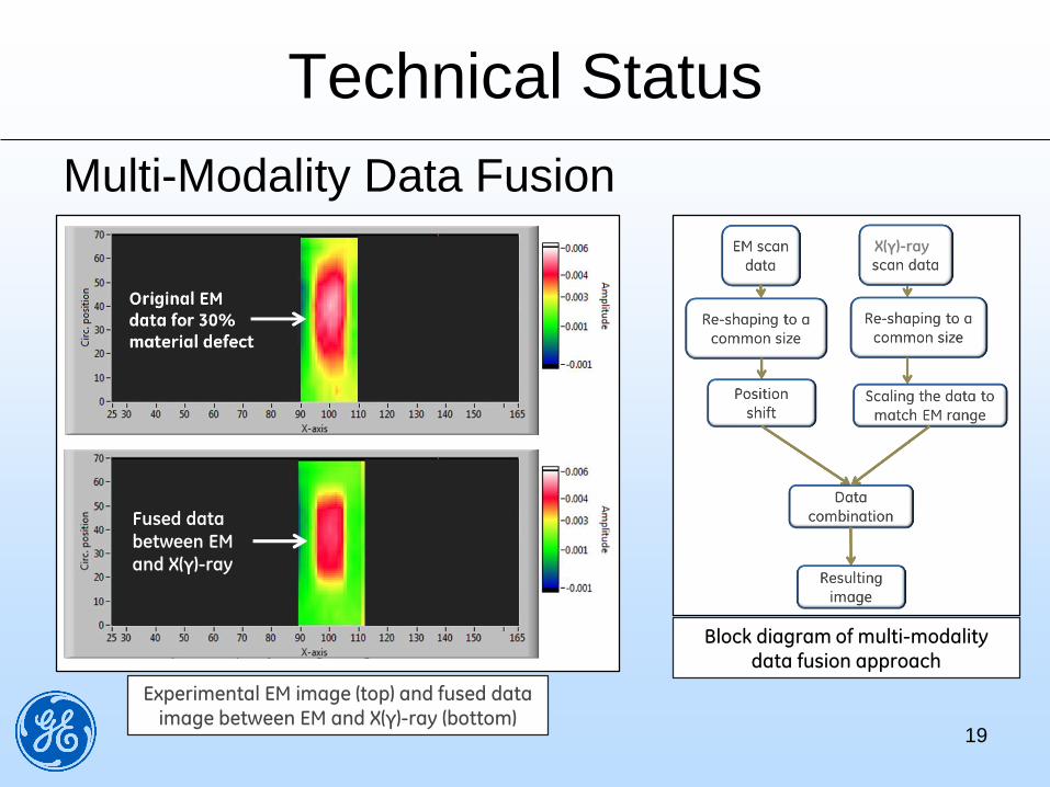
Multi-Modality Data Fusion
Experimental EM image (top) and fused data image between EM and X(γ)-ray (bottom)
Fused data
between EM
and X(γ)-ray
Block diagram of multi-modality data fusion approach
19
X(γ)-ray

Technical Status
Test Pit Testing
Schematic Sketch of Test Pit Setup
Test Plan:
• Testing of neutron, X(γ)-ray, and EM modality in vertical test pit
• Using multi-casing well phantom with engineered defects
• Performance characterization for each modality
• Data fusion between modalities
GE Oil & Gas Test Facility
Multi-Casing Well Phantom

Accomplishments to Date
• Established capabilities of high-energy modalities (neutron
and X(γ)-ray backscatter based detection) through Monte
Carlo N-Particle (MCNP) simulations.
• Built high- and low energy modality prototypes and performed
experiments in laboratory environment.
• Conducted data analysis and data fusion between
electromagnetic and X(γ)-ray modality.
• Optimized designs for all inspection modalities.
21

Synergy Opportunities
• Collaboration with DOE projects such as:
Integrated Wellbore Integrity Analysis Program for CO2 Storage
Applications - Battelle Memorial Institute
Wellbore and Seal Integrity - Los Alamos National Laboratory
Improving Science-Base for Wellbore Integrity, Barrier Interface
Performance – National Energy Technology Laboratory
• Joint test well preparation with engineered structural
flaws in multi-casing/multi cement annuli for field
testing and performance evaluation.
22

Summary
• Key Findings
• X(γ)-ray modality can detect defects as small ⅛’’ in diameter at
distance up to 3.5’’ past the first casing (through MCNP
simulations).
• Neutron modality provides azimuthal defect resolution between
defects such as air voids, cement, or high-density polyethylene.
• Electromagnetic inspection modality detects material loss in 1st
casing and directional eccentricity between 1st and 2nd casing.
• Data fusion between modalities can enhance detection
capabilities.
23

Summary
• Lessons Learned• Low ultrasound frequencies (<65kHz) are required to overcome
impedance mismatch between gas filled well and steel casing.
• Future Plans• Finalize design optimization, build subsystem prototypes, and
perform system calibration in controlled lab environment.
• Conduct performance analysis of nXis prototypes in vertical test
pit (multi-casing wellbore phantom with engineered defects).
• Perform data analysis & fusion between imaging modalities.
24

Acknowledgement
This report was prepared as an account of work sponsored by an
agency of the United States Government. Neither the United States
Government nor any agency thereof, nor any of their employees,
makes any warranty, express or implied, or assumes any legal liability
or responsibility for the accuracy, completeness, or usefulness of any
information, apparatus, product, or process disclosed, or represents
that its use would not infringe privately owned rights. Reference herein
to any specific commercial product, process or service by trade name,
trademark, manufacturer, or otherwise does not necessarily constitute
or imply its endorsement, recommendation, or favoring by the United
States Government of any agency thereof. The views and opinions of
authors expressed herein do not necessarily state or reflect those of
the United States Government or of any agency thereof.
25

Appendix
26

27
Organization Chart
Technical Review Team
GE Global Research
Jim LeBlanc, Technology Ldr. Loucas Tsakalakos, Lab Manager
Principal Investigator
Dr. Matthias Kasten
GE Oil & Gas
Mike Wells, Strategic COE Ldr. Guy Mason, Engineering Manager
Taylor Shinn, Innovation Adoption Ldr.
GE Global Research
NDE X(γ)-Ray & Neutron Detection/Imaging
Electromagnetic/Ultrasound System Integration Neutron Generator Design
Dr. Helene Climent X-Ray Photonics
Dr. Scott Price X-Ray Sources/Imaging
Dr. Frederick Wheeler Data Fusion
Dr. Adrian Ivan Detector Physics
Dr. William Ross NDE/X-Ray, γ-Ray
Edward J. Nieters NDE/Ultrasound
Dr. Yuri Plotnikov NDE/Eddy Current
Dr. Sergei Dolinsky Detector Physics
Brian E. Jurczyk

28
GE Project Team

29
GE Project Team

30
Starfire Industries Team

31
Technical Review Team

32
Gantt Chart

40%
33
Gantt Chart
60%
10%
The official program end date is September 30, 2016. However, a 6-months
no-cost extension has been requested to complete all the tasks.

Bibliography
Conference Presentations/ Proceedings:
• Y.A. Plotnikov, F.W. Wheeler, S. Mandal, W.R. Ross, J.S. Price, E.J. Nieters, A.
Ivan, S. Dolinsky, H.C. Climent, and A.M. Kasten, 2016, Review of Progress in
Quantitative NDE Conference: Development of an Electromagnetic Imaging System
for Well Bore Integrity Inspection. QNDE, July 2016, Atlanta, GA.
Accepted Conference Presentations:
• SPE Liquids-Rich Basins Conference, September 21-23, 2016, Midland, TX
• 2016 AIChE Annual Meeting, November 13-18, 2016, San Francisco, CA
Multiple patent disclosures have been filed. Journal publications will be
submitted after completion of technical work.
34