NVLAP Lab Code 200087-0 APPLICATION SUBMITTAL …cdn.lairdtech.com/home/brandworld/files/FCC and IC...
53
NVLAP Lab Code 200087-0 Rogers Labs, Inc. Laird Technologies FCC ID: KQL-RM024 4405 W. 259th Terrace Model: RM024 IC: 2268C-RM024 Louisburg, KS 66053 Test #: 120924 SN: ENG1 Phone/Fax: (913) 837-3214 Test to: FCC (15.247), RSS-210 Date: October 15, 2012 Revision 1 File: Laird RM024 TstRpt 120924 Page 1 of 53 APPLICATION SUBMITTAL REPORT FOR FCC And INDUSTRY CANADA GRANT OF CERTIFICATION FOR Model: RM024 2400.7-2470.9 MHz FHSS Transmission System FCC ID: KQL-RM024 IC: 2268C-RM024 FOR Laird Technologies 11160 Thompson Avenue Lenexa KS 66219 Test Report Number: 120924 Authorized Signatory: Scot D. Rogers
Transcript of NVLAP Lab Code 200087-0 APPLICATION SUBMITTAL …cdn.lairdtech.com/home/brandworld/files/FCC and IC...
NVLAP Lab Code 200087-0
Rogers Labs, Inc. Laird Technologies FCC ID: KQL-RM024
4405 W. 259th Terrace Model: RM024 IC: 2268C-RM024
Louisburg, KS 66053 Test #: 120924 SN: ENG1
Phone/Fax: (913) 837-3214 Test to: FCC (15.247), RSS-210 Date: October 15, 2012
Revision 1 File: Laird RM024 TstRpt 120924 Page 1 of 53
APPLICATION SUBMITTAL
REPORT
FOR
FCC And INDUSTRY CANADA
GRANT OF CERTIFICATION
FOR
Model: RM024
2400.7-2470.9 MHz
FHSS Transmission System
FCC ID: KQL-RM024
IC: 2268C-RM024
FOR
Laird Technologies 11160 Thompson Avenue
Lenexa KS 66219
Test Report Number: 120924
Authorized Signatory:
Scot D. Rogers
NVLAP Lab Code 200087-0
Rogers Labs, Inc. Laird Technologies FCC ID: KQL-RM024
4405 W. 259th Terrace Model: RM024 IC: 2268C-RM024
Louisburg, KS 66053 Test #: 120924 SN: ENG1
Phone/Fax: (913) 837-3214 Test to: FCC (15.247), RSS-210 Date: October 15, 2012
Revision 1 File: Laird RM024 TstRpt 120924 Page 2 of 53
Engineering Test Report
For Application Submittal for
Grant of Certification
FOR
CFR 47, PART 15C - Intentional Radiators Paragraph 15.247 and
Industry Canada, RSS-210
License Exempt Intentional Radiator
For
Laird Technologies 11160 Thompson Avenue
Lenexa KS 66219
Model: RM024
FHSS Transmission System
Frequency Range 2400.7-2470.9 MHz
FCC ID#: KQL-RM024
IC: 2268C-RM024
Test Date: September 24, 2012
Certifying Engineer:
Scot D. Rogers
Rogers Labs, Inc.
4405 West 259th
Terrace
Louisburg, KS 66053
Telephone/Facsimile: (913) 837-3214
This report shall not be reproduced except in full, without the written approval of the laboratory.
This report must not be used by the client to claim product endorsement by NVLAP, NIST, or
any agency of the U.S. Government.
ROGERS LABS, INC.
4405 West 259th
Terrace
Louisburg, KS 66053
Phone / Fax (913) 837-3214
NVLAP Lab Code 200087-0
Rogers Labs, Inc. Laird Technologies FCC ID: KQL-RM024
4405 W. 259th Terrace Model: RM024 IC: 2268C-RM024
Louisburg, KS 66053 Test #: 120924 SN: ENG1
Phone/Fax: (913) 837-3214 Test to: FCC (15.247), RSS-210 Date: October 15, 2012
Revision 1 File: Laird RM024 TstRpt 120924 Page 3 of 53
Table Of Contents
TABLE OF CONTENTS .................................................................................................. 3
REVISIONS ..................................................................................................................... 5
FORWARD ..................................................................................................................... 6
OPINION / INTERPRETATION OF RESULTS ............................................................... 6
STATEMENT OF MODIFICATIONS AND DEVIATIONS ............................................... 6
EQUIPMENT TESTED .................................................................................................... 7
EQUIPMENT FUNCTION AND CONFIGURATION........................................................ 7
Equipment Configuration.................................................................................................................................... 7
APPLICATION FOR CERTIFICATION ........................................................................... 8
APPLICABLE STANDARDS & TEST PROCEDURES .................................................. 9
EQUIPMENT TESTING PROCEDURES ........................................................................ 9
AC Line Conducted Emission Test Procedure .................................................................................................. 9
Diagram 1 Test arrangement for Conducted emissions ..................................................................................... 10
Radiated Emission Test Procedure ................................................................................................................... 11
Diagram 2 Test arrangement for radiated emissions of tabletop equipment ...................................................... 11
Diagram 3 Test arrangement for radiated emissions tested on Open Area Test Site (OATS) ........................... 12
LIST OF TEST EQUIPMENT ........................................................................................ 13
ENVIRONMENTAL CONDITIONS................................................................................ 14
TEST SITE LOCATIONS .............................................................................................. 14
UNITS OF MEASUREMENTS ...................................................................................... 14
INTENTIONAL RADIATORS ........................................................................................ 14
Antenna Requirements ...................................................................................................................................... 15
Restricted Bands of Operation .......................................................................................................................... 15

NVLAP Lab Code 200087-0
Rogers Labs, Inc. Laird Technologies FCC ID: KQL-RM024
4405 W. 259th Terrace Model: RM024 IC: 2268C-RM024
Louisburg, KS 66053 Test #: 120924 SN: ENG1
Phone/Fax: (913) 837-3214 Test to: FCC (15.247), RSS-210 Date: October 15, 2012
Revision 1 File: Laird RM024 TstRpt 120924 Page 4 of 53
Table 1 Radiated Emissions in Restricted Bands Data (General all antennas) .................................................. 15
Table 2 Radiated Emissions in Restricted Bands Data (2 dBi Chip Antenna)................................................... 16
Table 3 Radiated Emissions in Restricted Bands Data (1 dBi NZH Dipole Antenna) ...................................... 17
Table 4 Radiated Emissions in Restricted Bands Data (5 dBi Dipole Antenna) ............................................... 18
Table 5 Radiated Emissions in Restricted Bands Data (6 dBi Omni Antenna) ................................................. 19
Table 6 Radiated Emissions in Restricted Bands Data (9 dBi Panel Antenna) ................................................. 20
Summary of Results for Radiated Emissions in Restricted Bands ................................................................ 20
AC Line Conducted Emissions Procedure ....................................................................................................... 21
Figure One AC Line Conducted Emissions Line 1 ........................................................................................... 22
Figure Two AC Line Conducted Emissions Line 2 ........................................................................................... 22
Table 7 AC Line Conducted Emissions Data (7 Highest Emissions) ................................................................ 23
Summary of Results for AC Line Conducted Emissions ................................................................................ 23
General Radiated EMI Testing Procedure ...................................................................................................... 24
Table 8 General Radiated Emissions Data (worst-case all antennas) ................................................................ 25
Summary of Results for General Radiated Emissions .................................................................................... 25
Operation in the Band 2400 – 2483.5 MHz ...................................................................................................... 26
Figure Three of Antenna Port Conducted Emissions (43 Hop set) .................................................................... 26
Figure Four of Antenna Port Conducted Emissions (43 Hop set) ..................................................................... 27
Figure Five of Antenna Port Conducted Emissions (43 Hop set) ...................................................................... 27
Figure Six of Antenna Port Conducted Emissions (43 Hop set) ........................................................................ 28
Figure Seven of Antenna Port Conducted Emissions (43 Hop set) ................................................................... 28
Figure Eight of Antenna Port Conducted Emissions (43 Hop set) .................................................................... 29
Figure Nine of Antenna Port Conducted Emissions (79 Hop set) ..................................................................... 29
Figure Ten of Antenna Port Conducted Emissions (79 Hop set) ....................................................................... 30
Figure Eleven of Antenna Port Conducted Emissions (79 Hop set) .................................................................. 30
Figure Twelve of Antenna Port Conducted Emissions (79 Hop set) ................................................................. 31
Figure Thirteen of Antenna Port Conducted Emissions (79 Hop set) ............................................................... 31
Figure Fourteen of Antenna Port Conducted Emissions (79 Hop set) ............................................................... 32
Figure Fifteen Plot of Output Across Operational Band (43 Hop set) ............................................................... 32
Figure Sixteen Plot of 20-dB Occupied Bandwidth (Low Channel) (43 Hop set)............................................. 33
Figure Seventeen Plot of 20-dB Occupied Bandwidth (Middle Channel) (43 Hop set) .................................... 33
Figure Eighteen Plot of 20-dB Occupied Bandwidth (High Channel) (43 Hop set) .......................................... 34
Figure Nineteen Plot Channel Spacing (43 Hop set) ......................................................................................... 34
Figure Twenty Plot of Dwell time on Channel (43 Hop set) ............................................................................. 35
Figure Twenty-0ne Plot Channel Occupancy (43 Hop set) ............................................................................... 35
Figure Twenty-Two Plot of Low Band Edge (43 Hop set) ................................................................................ 36
Figure Twenty-Three Plot of High Band Edge (43 Hop set) ............................................................................. 36
NVLAP Lab Code 200087-0
Rogers Labs, Inc. Laird Technologies FCC ID: KQL-RM024
4405 W. 259th Terrace Model: RM024 IC: 2268C-RM024
Louisburg, KS 66053 Test #: 120924 SN: ENG1
Phone/Fax: (913) 837-3214 Test to: FCC (15.247), RSS-210 Date: October 15, 2012
Revision 1 File: Laird RM024 TstRpt 120924 Page 5 of 53
Figure Twenty-Four Plot of Output Across Operational Band (79 Hop set) ..................................................... 37
Figure Twenty-Five Plot of 20-dB Occupied Bandwidth (Low Channel) (79 Hop set) .................................... 37
Figure Twenty-Six Plot of 20-dB Occupied Bandwidth (Middle Channel) (79 Hop set) ................................. 38
Figure Twenty-Seven Plot of 20-dB Occupied Bandwidth (High Channel) (79 Hop set) ................................. 38
Figure Twenty-Eight Plot Channel Spacing (79 Hop set) ................................................................................. 39
Figure Twenty-Nine Plot of Dwell time on Channel (79 Hop set) .................................................................... 39
Figure Thirty Plot Channel Occupancy (79 Hop set) ........................................................................................ 40
Figure Thirty-One Plot of Low Band Edge (79 Hop set) .................................................................................. 40
Figure Thirty -Two Plot of High Band Edge (79 Hop set) ................................................................................ 41
Transmitter Emissions Data .............................................................................................................................. 41
Table 9 Transmitter Antenna Conducted Emissions Data ................................................................................. 41
Table 10 Transmitter Radiated Emission Data (2 dBi Chip Antenna) ............................................................... 42
Table 11 Transmitter Radiated Emission Data (1 dBi NZH PCB Dipole Antenna) .......................................... 43
Table 12 Transmitter Radiated Emission Data (5 dBi Dipole Antenna)............................................................ 44
Table 13 Transmitter Radiated Emission Data (6 dBi Omni Antenna) ............................................................. 45
Table 14 Transmitter Radiated Emission Data (9 dBi Panel Antenna) ............................................................. 46
Summary of Results for Radiated Emissions of Intentional Radiator .......................................................... 47
ANNEX .......................................................................................................................... 48
Annex A Measurement Uncertainty Calculations ........................................................................................... 49
Annex B Rogers Labs Test Equipment List ..................................................................................................... 50
Annex C Rogers Qualifications ......................................................................................................................... 51
Annex D FCC Site Registration Letter ............................................................................................................. 52
Annex E Industry Canada Site Registration Letter ........................................................................................ 53
Revisions Revision 1, Report Issued October 15, 2012

NVLAP Lab Code 200087-0
Rogers Labs, Inc. Laird Technologies FCC ID: KQL-RM024
4405 W. 259th Terrace Model: RM024 IC: 2268C-RM024
Louisburg, KS 66053 Test #: 120924 SN: ENG1
Phone/Fax: (913) 837-3214 Test to: FCC (15.247), RSS-210 Date: October 15, 2012
Revision 1 File: Laird RM024 TstRpt 120924 Page 6 of 53
Forward
The following information is submitted for consideration in obtaining Grant of Certification for
License Exempt FHSS Intentional Radiator operating under CFR 47 Paragraph 15.247 and
Industry Canada RSS-210.
Name of Applicant: Laird Technologies
11160 Thompson Avenue
Lenexa KS 66219
Model: RM024
FCC I.D.: KQL-RM024 IC: 2268C-RM024
Frequency Range: 2400.7-2470.9 MHz
Operating Power: 20.4 dBm, 110 mW (antenna port conducted) (0.11 Watts), Occupied
Bandwidth 841.3 kHz (79 hop set) or 1.07 MHz (43 hop set),
Antennas supported (Integral chip 2 dBi, PCB Dipole 1 dBi, Dipole 5
dBi, Omni 6 dBi, Panel 9 dBi)
Opinion / Interpretation of Results
Test Performed Minimum
Margin (dB)
Results
Antenna requirement per CFR 47 15.203 N/A Complies
Restricted Bands (General Emissions) from Support Equipment (* Note1) -4.8* Complies
Restricted Bands (Tx) Emissions as per CFR 47 15.205 and RSS-210 -22.0 Complies
AC Line Conducted Emissions as per CFR 47 15.207 -28.0 Complies
Radiated Emissions as per CFR 47 15.209 and RSS-210 (* Note 1) -4.8* Complies
Radiated Emissions per CFR 47 15.247 and RSS-210 (harmonics) -24.1 Complies
*Note 1) General Radiated emissions emanated from test setup support computer system
presented highest general radiated emission and lowest radiated emission margin as presented.
Statement of Modifications and Deviations
No modifications to the EUT were required for the unit to demonstrate compliance with the CFR47
Part 15C or RSS-210 emissions requirements. There were no deviations or exceptions to the
specifications.

NVLAP Lab Code 200087-0
Rogers Labs, Inc. Laird Technologies FCC ID: KQL-RM024
4405 W. 259th Terrace Model: RM024 IC: 2268C-RM024
Louisburg, KS 66053 Test #: 120924 SN: ENG1
Phone/Fax: (913) 837-3214 Test to: FCC (15.247), RSS-210 Date: October 15, 2012
Revision 1 File: Laird RM024 TstRpt 120924 Page 7 of 53
Equipment Tested
Equipment Model FCC I.D. #
EUT RM024 KQL-RM024
CPU HP CRVSA-02T1-75 TW24416178
2 dBi Chip WIC2450A N/A
1 dBi PCB Dipole NZH2400-MMCX N/A
5 dBi Dipole S151-6-PX-2450S N/A
6 dBi Omni IG2450-RS36 N/A
9 dBi Panel ID2450-RS36 N/A
Antennas (2 dBi Integral chip, 6 dBi Omni, 9dBi Panel, 5dBi Dipole, 1 dBi PCB Dipole)
Equipment Function and Configuration
The EUT is a 2400.7-2470.9 MHz Frequency Hopping Spread Spectrum Transceiver Module
used to transmit data in applications offering wireless connectivity. The design offer operation
in either 43 hop set or 79 hop set mode. The equipment is marketed for use to incorporate a
wireless link to exchange data information from one point to another. The design offers two
antenna options (PCB mounted chip antenna and u.fl connection). For testing purposes the
RM024 transceiver was connected to the manufacturer supplied test fixture, AC/DC power
adapter, and communicating to the laptop computer allowing for data communications and
operational control of the transmitter. The RM024 received power from the test fixture and
offers no other provision for connection to I/O or utility power systems. Preliminary
investigation was performed for all channel bandwidths and modes of operation. Testing of the
RM024 and support equipment was performed with the EUT placed on the test fixture, powered
from the AC/DC power adapter, and set to transmit in all available data modes and channels.
Equipment Configuration
RS-232 Cable
Coaxial Cable
(EUT)
Placed on Test
Fixture
Laptop Computer
AC Power Adapter
Utility Power
Optional
External
Antenna
AC Power Adapter
NVLAP Lab Code 200087-0
Rogers Labs, Inc. Laird Technologies FCC ID: KQL-RM024
4405 W. 259th Terrace Model: RM024 IC: 2268C-RM024
Louisburg, KS 66053 Test #: 120924 SN: ENG1
Phone/Fax: (913) 837-3214 Test to: FCC (15.247), RSS-210 Date: October 15, 2012
Revision 1 File: Laird RM024 TstRpt 120924 Page 8 of 53
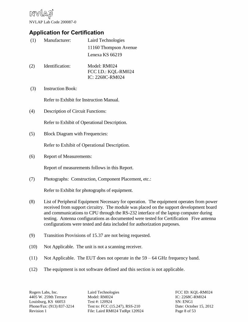
Application for Certification
(1) Manufacturer: Laird Technologies
11160 Thompson Avenue
Lenexa KS 66219
(2) Identification: Model: RM024
FCC I.D.: KQL-RM024
IC: 2268C-RM024
(3) Instruction Book:
Refer to Exhibit for Instruction Manual.
(4) Description of Circuit Functions:
Refer to Exhibit of Operational Description.
(5) Block Diagram with Frequencies:
Refer to Exhibit of Operational Description.
(6) Report of Measurements:
Report of measurements follows in this Report.
(7) Photographs: Construction, Component Placement, etc.:
Refer to Exhibit for photographs of equipment.
(8) List of Peripheral Equipment Necessary for operation. The equipment operates from power
received from support circuitry. The module was placed on the support development board
and communications to CPU through the RS-232 interface of the laptop computer during
testing. Antenna configurations as documented were tested for Certification Five antenna
configurations were tested and data included for authorization purposes.
(9) Transition Provisions of 15.37 are not being requested.
(10) Not Applicable. The unit is not a scanning receiver.
(11) Not Applicable. The EUT does not operate in the 59 – 64 GHz frequency band.
(12) The equipment is not software defined and this section is not applicable.

NVLAP Lab Code 200087-0
Rogers Labs, Inc. Laird Technologies FCC ID: KQL-RM024
4405 W. 259th Terrace Model: RM024 IC: 2268C-RM024
Louisburg, KS 66053 Test #: 120924 SN: ENG1
Phone/Fax: (913) 837-3214 Test to: FCC (15.247), RSS-210 Date: October 15, 2012
Revision 1 File: Laird RM024 TstRpt 120924 Page 9 of 53
Applicable Standards & Test Procedures
In accordance with the Federal Communications Code of Federal Regulations, dated October 1,
2011, Part 2, Subpart J, Paragraphs 2.907, 2.911, 2.913, 2.925, 2.926, 2.1031 through 2.1057, and
applicable parts of paragraph 15, Part 15C Paragraph 15.247 and Industry Canada standard RSS-210
Issue 8 the following information is submitted. Test procedures used are the established Methods of
Measurement of Radio-Noise Emissions as described in the ANSI C63.4-2009, FCC documents
KDB 996369, DA00-1407, and DA00-705 and/or TIA/EIA 603-1. Testing for the AC line-
conducted emissions were performed as defined in sections 7 and 13.1.3, testing of the radiated
emissions was performed as defined in sections 8 and 13.1.4 of ANSI C63.4-2009. Testing of the
intentional radiated emissions was performed as defined in section 13 of ANSI C63.4-2009.
Equipment Testing Procedures
AC Line Conducted Emission Test Procedure
The EUT operates from DC power only received from host support equipment and must be
connected to supporting circuitry for power and interface communications. For testing purposes the
EUT was placed on the development support board (test fixture) and communicating to the computer
allowing for operational control of the transmitter and communications. For testing purposes, the
manufacturer supplied AC/DC power adapter was used to power the test fixture and system. The
EUT operates from DC power only and must be connected to an approved AC/DC adapter for
operation. For testing purposes, the manufacturer supplied AC/DC power adapter was used to power
the EUT. Testing for the AC line-conducted emissions testing was performed as defined in sections
7 and 13.1.3 of ANSI C63.4-2009. The test setup including the EUT was arranged in typical
equipment configurations and placed on a 1 x 1.5-meter wooden bench, 0.8 meters high located in a
screen room. The power lines of the system were isolated from the power source using a standard
LISN with a 50-µHy choke. EMI was coupled to the spectrum analyzer through a 0.1 µF capacitor
internal to the LISN. The LISN was positioned on the floor beneath the wooden bench supporting
the EUT. The power lines and cables were draped over the back edge of the table. Refer to diagram
1 showing typical test arrangement and photographs in the test setup exhibits for specific EUT
placement during testing. Refer to photographs in the test setup exhibits for EUT placement during
testing.

NVLAP Lab Code 200087-0
Rogers Labs, Inc. Laird Technologies FCC ID: KQL-RM024
4405 W. 259th Terrace Model: RM024 IC: 2268C-RM024
Louisburg, KS 66053 Test #: 120924 SN: ENG1
Phone/Fax: (913) 837-3214 Test to: FCC (15.247), RSS-210 Date: October 15, 2012
Revision 1 File: Laird RM024 TstRpt 120924 Page 10 of 53
Diagram 1 Test arrangement for Conducted emissions
1. Interconnecting cables that hang closer than 40 cm to the ground plane were folded back and
forth in the center forming a bundle 30 cm to 40 cm long.
2. Input/output (I/O) cables that are not connected to a peripheral shall be bundled in the center.
The end of the cable may be terminated, if required, using the correct terminating impedance.
The overall length shall not exceed 1 m.
3. EUT connected to one LISN. Unused LISN measuring port connectors are terminated into 50
Ω loads. LISN is placed on top of and bonded to reference ground plane.
3.1 All other equipment powered from additional LISN(s).
3.2 Multiple outlet strips can be used for multiple power cords of non-EUT equipment.
3.3 LISN is positioned at least 80 cm from nearest part of EUT chassis.
4. Cables of hand-operated devices, such as keyboards, mice, and so on, shall be placed as for
normal use.
5. Non-EUT components of EUT system being tested.
6. Rear of EUT, including peripherals, shall all be aligned and flush with rear of tabletop.
7. Rear of tabletop shall be 40 cm removed from a vertical conducting plane that is bonded to the
ground plane (see 5.2.2 for options).

NVLAP Lab Code 200087-0
Rogers Labs, Inc. Laird Technologies FCC ID: KQL-RM024
4405 W. 259th Terrace Model: RM024 IC: 2268C-RM024
Louisburg, KS 66053 Test #: 120924 SN: ENG1
Phone/Fax: (913) 837-3214 Test to: FCC (15.247), RSS-210 Date: October 15, 2012
Revision 1 File: Laird RM024 TstRpt 120924 Page 11 of 53
Radiated Emission Test Procedure
The EUT was placed on a rotating 1 x 1.5-meter wooden platform, 0.8 meters above the ground
plane at a distance of 3 meters from the FSM antenna. Testing for the radiated emissions was
performed as required by CFR47 15, RSS-210 and specified in sections 8 and 13.1.4 of ANSI
C63.4-2009. EMI energy was maximized by equipment placement, raising and lowering the
FSM antenna, changing the antenna polarization, and by rotating the turntable. Each emission
was maximized before data was taken using a spectrum analyzer. The frequency spectrum from
9 kHz to 25,000 MHz was searched for during preliminary investigation. Refer to diagrams 2
and 3 showing typical test arrangement and photographs in the test setup exhibits for specific
EUT placement during testing.
Diagram 2 Test arrangement for radiated emissions of tabletop equipment
1. Interconnecting cables that hang closer than 40 cm to the ground plane shall be folded back
and forth in the center, forming a bundle 30 cm to 40 cm long.

NVLAP Lab Code 200087-0
Rogers Labs, Inc. Laird Technologies FCC ID: KQL-RM024
4405 W. 259th Terrace Model: RM024 IC: 2268C-RM024
Louisburg, KS 66053 Test #: 120924 SN: ENG1
Phone/Fax: (913) 837-3214 Test to: FCC (15.247), RSS-210 Date: October 15, 2012
Revision 1 File: Laird RM024 TstRpt 120924 Page 12 of 53
2. I/O cables that are not connected to a peripheral shall be bundled in the center. The end of the
cable may be terminated if required using the correct terminating impedance. The total length
shall not exceed 1 m.
3. If LISNs are kept in the test setup for radiated emissions, it is preferred that they be installed
under the ground plane with the receptacle flush with the ground plane.
4. Cables of hand-operated devices, such as keyboards, mice, and so on, shall be placed as for
normal use.
5. Non-EUT components of EUT system being tested.
6. Rear of EUT, including peripherals, shall all be aligned and flush with rear of tabletop
(possibly center of table for transmitter equipment).
7. No vertical conducting plane used.
8. Power cords drape to the floor and are routed over to receptacle.
Diagram 3 Test arrangement for radiated emissions tested on Open Area Test Site (OATS)

NVLAP Lab Code 200087-0
Rogers Labs, Inc. Laird Technologies FCC ID: KQL-RM024
4405 W. 259th Terrace Model: RM024 IC: 2268C-RM024
Louisburg, KS 66053 Test #: 120924 SN: ENG1
Phone/Fax: (913) 837-3214 Test to: FCC (15.247), RSS-210 Date: October 15, 2012
Revision 1 File: Laird RM024 TstRpt 120924 Page 13 of 53
List of Test Equipment
A Rohde and Schwarz ESU40 and/or Hewlett Packard 8591EM was used as the measuring
device for the emissions testing of frequencies below 1 GHz. A Rohde and Schwarz ESU40
and/or Hewlett Packard 8562A Spectrum Analyzer was used as the measuring device for testing
the emissions at frequencies above 1 GHz. The analyzer settings used are described in the
following table. Refer to the appendix for a complete list of test equipment.
AC Line Conducted Emissions (0.150 -30 MHz)
RBW AVG. BW Detector Function
9 kHz 30 kHz Peak / Quasi Peak
Emissions (30-1000 MHz)
RBW AVG. BW Detector Function
120 kHz 300 kHz Peak / Quasi Peak
Emissions (Above 1000 MHz)
RBW Video BW Detector Function
100 kHz 100 kHz Peak
1 MHz 1 MHz Peak / Average
Equipment Manufacturer Model Band Cal Date Due
LISN Comp. Design FCC-LISN-2-MOD.CD .15-30MHz 10/11 10/12
Antenna ARA BCD-235-B 20-350MHz 10/11 10/12
Antenna EMCO 3147 200-1000MHz 10/11 10/12
Antenna Com Power AH-118 1-18 GHz 10/11 10/12
Antenna Com Power AH-840 18-40 GHz 10/11 10/12
Antenna Standard FXRY638A 10-18 GHz 3/12 5/13
Antenna EMCO 6509 .001-30 MHz 2/12 2/13
Antenna EMCO 3143 20-1200 MHz 5/12 5/13
Antenna Sunol JB-6 30-1000 MHz 5/12 5/13
Analyzer HP 8591EM 9kHz-1.8GHz 5/12 5/13
Analyzer HP 8562A 9kHz-110GHz 5/12 5/13
Analyzer Rohde & Schwarz ESU40 20Hz-40GHz 5/12 5/13
Amplifier Com-Power PA-010 100Hz-30MHz 10/11 10/12
Amplifier Com-Power CPPA-102 1-1000 MHz 10/11 10/12
Amplifier Com-Power PA-22 0.5-22 GHz 10/11 10/12
NVLAP Lab Code 200087-0
Rogers Labs, Inc. Laird Technologies FCC ID: KQL-RM024
4405 W. 259th Terrace Model: RM024 IC: 2268C-RM024
Louisburg, KS 66053 Test #: 120924 SN: ENG1
Phone/Fax: (913) 837-3214 Test to: FCC (15.247), RSS-210 Date: October 15, 2012
Revision 1 File: Laird RM024 TstRpt 120924 Page 14 of 53
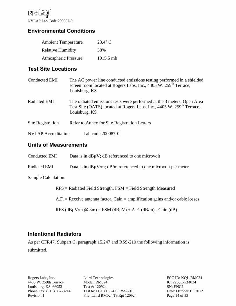
Environmental Conditions
Ambient Temperature 23.4° C
Relative Humidity 38%
Atmospheric Pressure 1015.5 mb
Test Site Locations
Conducted EMI The AC power line conducted emissions testing performed in a shielded
screen room located at Rogers Labs, Inc., 4405 W. 259th
Terrace,
Louisburg, KS
Radiated EMI The radiated emissions tests were performed at the 3 meters, Open Area
Test Site (OATS) located at Rogers Labs, Inc., 4405 W. 259th
Terrace,
Louisburg, KS
Site Registration Refer to Annex for Site Registration Letters
NVLAP Accreditation Lab code 200087-0
Units of Measurements
Conducted EMI Data is in dBµV; dB referenced to one microvolt
Radiated EMI Data is in dBµV/m; dB/m referenced to one microvolt per meter
Sample Calculation:
RFS = Radiated Field Strength, FSM = Field Strength Measured
A.F. = Receive antenna factor, Gain = amplification gains and/or cable losses
RFS (dBµV/m @ 3m) = FSM (dBµV) + A.F. (dB/m) - Gain (dB)
Intentional Radiators
As per CFR47, Subpart C, paragraph 15.247 and RSS-210 the following information is
submitted.
NVLAP Lab Code 200087-0
Rogers Labs, Inc. Laird Technologies FCC ID: KQL-RM024
4405 W. 259th Terrace Model: RM024 IC: 2268C-RM024
Louisburg, KS 66053 Test #: 120924 SN: ENG1
Phone/Fax: (913) 837-3214 Test to: FCC (15.247), RSS-210 Date: October 15, 2012
Revision 1 File: Laird RM024 TstRpt 120924 Page 15 of 53
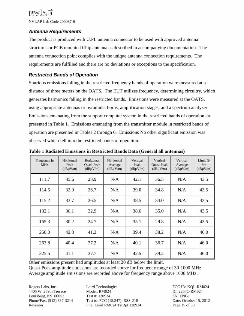
Antenna Requirements
The product is produced with U.FL antenna connector to be used with approved antenna
structures or PCB mounted Chip antenna as described in accompanying documentation. The
antenna connection point complies with the unique antenna connection requirements. The
requirements are fulfilled and there are no deviations or exceptions to the specification.
Restricted Bands of Operation
Spurious emissions falling in the restricted frequency bands of operation were measured at a
distance of three meters on the OATS. The EUT utilizes frequency, determining circuitry, which
generates harmonics falling in the restricted bands. Emissions were measured at the OATS,
using appropriate antennas or pyramidal horns, amplification stages, and a spectrum analyzer.
Emissions emanating from the support computer system in the restricted bands of operation are
presented in Table 1. Emissions emanating from the transmitter module in restricted bands of
operation are presented in Tables 2 through 6. Emissions No other significant emission was
observed which fell into the restricted bands of operation.
Table 1 Radiated Emissions in Restricted Bands Data (General all antennas)
Frequency in
MHz
Horizontal
Peak
(dBµV/m)
Horizontal
Quasi-Peak
(dBµV/m)
Horizontal
Average
(dBµV/m)
Vertical
Peak
(dBµV/m)
Vertical
Quasi-Peak
(dBµV/m)
Vertical
Average
(dBµV/m)
Limit @
3m
(dBµV/m)
111.7 35.6 28.9 N/A 42.1 36.5 N/A 43.5
114.6 32.9 26.7 N/A 39.0 34.8 N/A 43.5
115.2 33.7 26.5 N/A 38.5 34.0 N/A 43.5
132.1 36.1 32.9 N/A 38.6 35.0 N/A 43.5
165.3 30.2 24.7 N/A 35.1 29.8 N/A 43.5
250.0 42.3 41.2 N/A 39.4 38.2 N/A 46.0
263.8 40.4 37.2 N/A 40.1 36.7 N/A 46.0
325.5 41.1 37.7 N/A 42.5 39.2 N/A 46.0
Other emissions present had amplitudes at least 20 dB below the limit.
Quasi-Peak amplitude emissions are recorded above for frequency range of 30-1000 MHz.
Average amplitude emissions are recorded above for frequency range above 1000 MHz.
NVLAP Lab Code 200087-0
Rogers Labs, Inc. Laird Technologies FCC ID: KQL-RM024
4405 W. 259th Terrace Model: RM024 IC: 2268C-RM024
Louisburg, KS 66053 Test #: 120924 SN: ENG1
Phone/Fax: (913) 837-3214 Test to: FCC (15.247), RSS-210 Date: October 15, 2012
Revision 1 File: Laird RM024 TstRpt 120924 Page 16 of 53
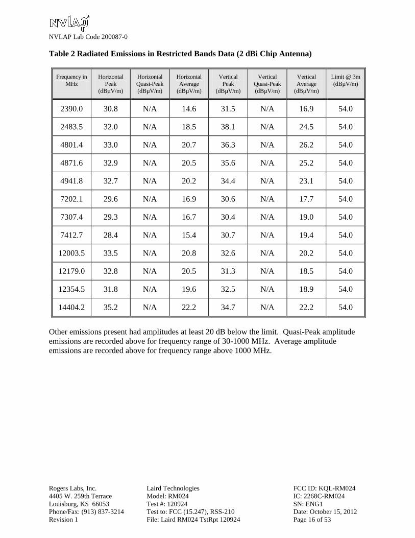
Table 2 Radiated Emissions in Restricted Bands Data (2 dBi Chip Antenna)
Frequency in
MHz
Horizontal
Peak
(dBµV/m)
Horizontal
Quasi-Peak
(dBµV/m)
Horizontal
Average
(dBµV/m)
Vertical
Peak
(dBµV/m)
Vertical
Quasi-Peak
(dBµV/m)
Vertical
Average
(dBµV/m)
Limit @ 3m
(dBµV/m)
2390.0 30.8 N/A 14.6 31.5 N/A 16.9 54.0
2483.5 32.0 N/A 18.5 38.1 N/A 24.5 54.0
4801.4 33.0 N/A 20.7 36.3 N/A 26.2 54.0
4871.6 32.9 N/A 20.5 35.6 N/A 25.2 54.0
4941.8 32.7 N/A 20.2 34.4 N/A 23.1 54.0
7202.1 29.6 N/A 16.9 30.6 N/A 17.7 54.0
7307.4 29.3 N/A 16.7 30.4 N/A 19.0 54.0
7412.7 28.4 N/A 15.4 30.7 N/A 19.4 54.0
12003.5 33.5 N/A 20.8 32.6 N/A 20.2 54.0
12179.0 32.8 N/A 20.5 31.3 N/A 18.5 54.0
12354.5 31.8 N/A 19.6 32.5 N/A 18.9 54.0
14404.2 35.2 N/A 22.2 34.7 N/A 22.2 54.0
Other emissions present had amplitudes at least 20 dB below the limit. Quasi-Peak amplitude
emissions are recorded above for frequency range of 30-1000 MHz. Average amplitude
emissions are recorded above for frequency range above 1000 MHz.
NVLAP Lab Code 200087-0
Rogers Labs, Inc. Laird Technologies FCC ID: KQL-RM024
4405 W. 259th Terrace Model: RM024 IC: 2268C-RM024
Louisburg, KS 66053 Test #: 120924 SN: ENG1
Phone/Fax: (913) 837-3214 Test to: FCC (15.247), RSS-210 Date: October 15, 2012
Revision 1 File: Laird RM024 TstRpt 120924 Page 17 of 53
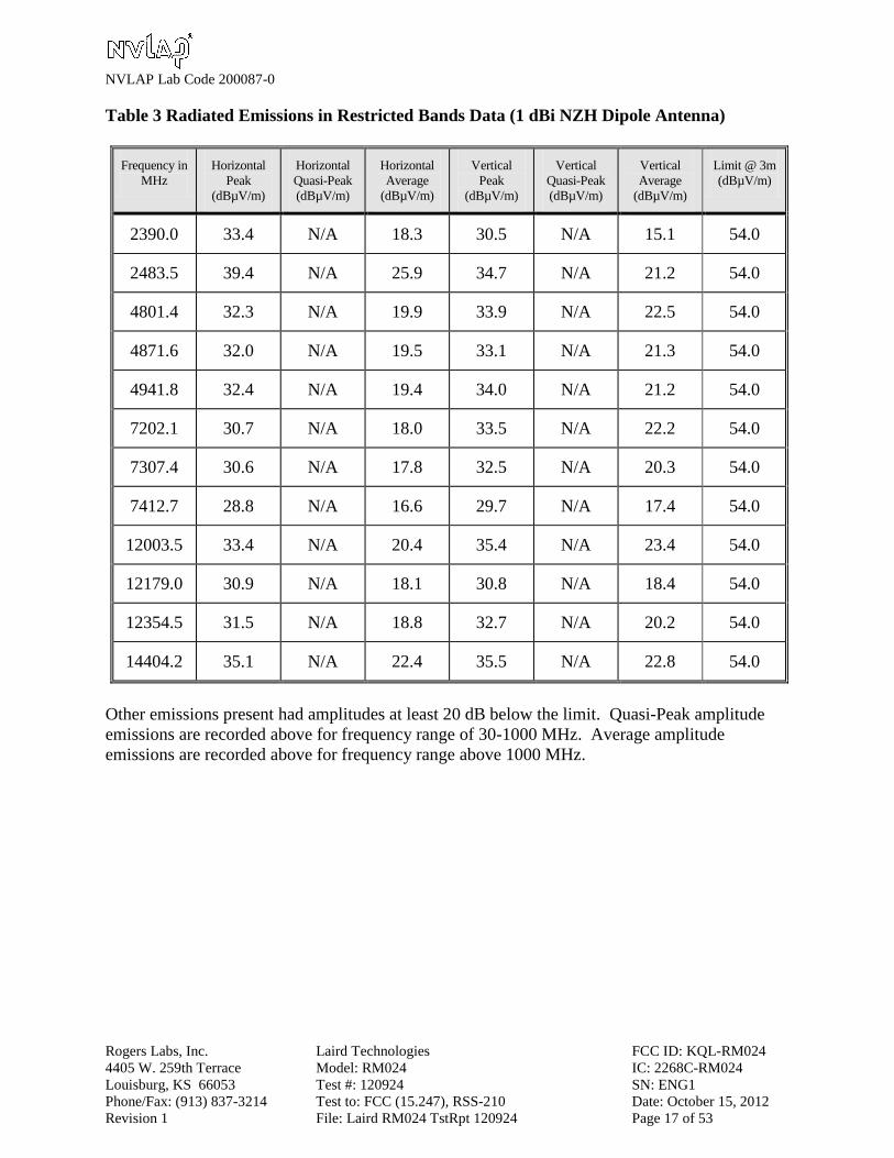
Table 3 Radiated Emissions in Restricted Bands Data (1 dBi NZH Dipole Antenna)
Frequency in
MHz
Horizontal
Peak
(dBµV/m)
Horizontal
Quasi-Peak
(dBµV/m)
Horizontal
Average
(dBµV/m)
Vertical
Peak
(dBµV/m)
Vertical
Quasi-Peak
(dBµV/m)
Vertical
Average
(dBµV/m)
Limit @ 3m
(dBµV/m)
2390.0 33.4 N/A 18.3 30.5 N/A 15.1 54.0
2483.5 39.4 N/A 25.9 34.7 N/A 21.2 54.0
4801.4 32.3 N/A 19.9 33.9 N/A 22.5 54.0
4871.6 32.0 N/A 19.5 33.1 N/A 21.3 54.0
4941.8 32.4 N/A 19.4 34.0 N/A 21.2 54.0
7202.1 30.7 N/A 18.0 33.5 N/A 22.2 54.0
7307.4 30.6 N/A 17.8 32.5 N/A 20.3 54.0
7412.7 28.8 N/A 16.6 29.7 N/A 17.4 54.0
12003.5 33.4 N/A 20.4 35.4 N/A 23.4 54.0
12179.0 30.9 N/A 18.1 30.8 N/A 18.4 54.0
12354.5 31.5 N/A 18.8 32.7 N/A 20.2 54.0
14404.2 35.1 N/A 22.4 35.5 N/A 22.8 54.0
Other emissions present had amplitudes at least 20 dB below the limit. Quasi-Peak amplitude
emissions are recorded above for frequency range of 30-1000 MHz. Average amplitude
emissions are recorded above for frequency range above 1000 MHz.

NVLAP Lab Code 200087-0
Rogers Labs, Inc. Laird Technologies FCC ID: KQL-RM024
4405 W. 259th Terrace Model: RM024 IC: 2268C-RM024
Louisburg, KS 66053 Test #: 120924 SN: ENG1
Phone/Fax: (913) 837-3214 Test to: FCC (15.247), RSS-210 Date: October 15, 2012
Revision 1 File: Laird RM024 TstRpt 120924 Page 18 of 53
Table 4 Radiated Emissions in Restricted Bands Data (5 dBi Dipole Antenna)
Frequency in
MHz
Horizontal
Peak
(dBµV/m)
Horizontal
Quasi-Peak
(dBµV/m)
Horizontal
Average
(dBµV/m)
Vertical
Peak
(dBµV/m)
Vertical
Quasi-Peak
(dBµV/m)
Vertical
Average
(dBµV/m)
Limit @ 3m
(dBµV/m)
2390.0 28.0 N/A 14.2 34.3 N/A 19.1 54.0
2483.5 33.9 N/A 21.0 43.0 N/A 29.1 54.0
4801.4 33.1 N/A 21.0 36.3 N/A 25.4 54.0
4871.6 32.2 N/A 19.9 34.3 N/A 23.4 54.0
4941.8 33.5 N/A 20.7 35.9 N/A 25.2 54.0
7202.1 30.7 N/A 17.2 32.0 N/A 20.5 54.0
7307.4 31.2 N/A 18.8 30.5 N/A 17.7 54.0
7412.7 29.5 N/A 17.2 29.7 N/A 17.6 54.0
12003.5 33.4 N/A 20.8 36.6 N/A 24.2 54.0
12179.0 30.4 N/A 18.3 35.3 N/A 23.5 54.0
12354.5 33.2 N/A 19.9 35.3 N/A 23.9 54.0
14404.2 35.5 N/A 22.4 35.1 N/A 22.5 54.0
Other emissions present had amplitudes at least 20 dB below the limit. Quasi-Peak amplitude
emissions are recorded above for frequency range of 30-1000 MHz. Average amplitude
emissions are recorded above for frequency range above 1000 MHz.
NVLAP Lab Code 200087-0
Rogers Labs, Inc. Laird Technologies FCC ID: KQL-RM024
4405 W. 259th Terrace Model: RM024 IC: 2268C-RM024
Louisburg, KS 66053 Test #: 120924 SN: ENG1
Phone/Fax: (913) 837-3214 Test to: FCC (15.247), RSS-210 Date: October 15, 2012
Revision 1 File: Laird RM024 TstRpt 120924 Page 19 of 53
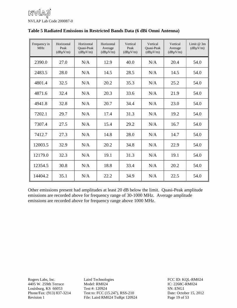
Table 5 Radiated Emissions in Restricted Bands Data (6 dBi Omni Antenna)
Frequency in
MHz
Horizontal
Peak
(dBµV/m)
Horizontal
Quasi-Peak
(dBµV/m)
Horizontal
Average
(dBµV/m)
Vertical
Peak
(dBµV/m)
Vertical
Quasi-Peak
(dBµV/m)
Vertical
Average
(dBµV/m)
Limit @ 3m
(dBµV/m)
2390.0 27.0 N/A 12.9 40.0 N/A 20.4 54.0
2483.5 28.0 N/A 14.5 28.5 N/A 14.5 54.0
4801.4 32.5 N/A 20.2 35.3 N/A 25.2 54.0
4871.6 32.4 N/A 20.3 33.6 N/A 21.9 54.0
4941.8 32.8 N/A 20.7 34.4 N/A 23.0 54.0
7202.1 29.7 N/A 17.4 31.3 N/A 19.2 54.0
7307.4 27.5 N/A 15.4 29.2 N/A 16.7 54.0
7412.7 27.3 N/A 14.8 28.0 N/A 14.7 54.0
12003.5 32.9 N/A 20.2 34.8 N/A 22.9 54.0
12179.0 32.3 N/A 19.1 31.3 N/A 19.1 54.0
12354.5 30.8 N/A 18.8 33.4 N/A 20.2 54.0
14404.2 35.1 N/A 22.2 34.9 N/A 22.5 54.0
Other emissions present had amplitudes at least 20 dB below the limit. Quasi-Peak amplitude
emissions are recorded above for frequency range of 30-1000 MHz. Average amplitude
emissions are recorded above for frequency range above 1000 MHz.

NVLAP Lab Code 200087-0
Rogers Labs, Inc. Laird Technologies FCC ID: KQL-RM024
4405 W. 259th Terrace Model: RM024 IC: 2268C-RM024
Louisburg, KS 66053 Test #: 120924 SN: ENG1
Phone/Fax: (913) 837-3214 Test to: FCC (15.247), RSS-210 Date: October 15, 2012
Revision 1 File: Laird RM024 TstRpt 120924 Page 20 of 53
Table 6 Radiated Emissions in Restricted Bands Data (9 dBi Panel Antenna)
Frequency in
MHz
Horizontal
Peak
(dBµV/m)
Horizontal
Quasi-Peak
(dBµV/m)
Horizontal
Average
(dBµV/m)
Vertical
Peak
(dBµV/m)
Vertical
Quasi-Peak
(dBµV/m)
Vertical
Average
(dBµV/m)
Limit @ 3m
(dBµV/m)
2390.0 28.7 N/A 14.7 39.9 N/A 24.1 54.0
2483.5 34.0 N/A 21.2 45.4 N/A 32.0 54.0
4801.4 32.4 N/A 20.3 35.3 N/A 23.8 54.0
4871.6 32.4 N/A 20.0 33.3 N/A 21.3 54.0
4941.8 32.1 N/A 19.8 32.7 N/A 19.9 54.0
7202.1 30.0 N/A 17.4 32.0 N/A 17.6 54.0
7307.4 34.1 N/A 17.5 30.2 N/A 18.0 54.0
7412.7 28.7 N/A 16.4 30.5 N/A 17.0 54.0
12003.5 32.8 N/A 20.3 34.2 N/A 21.5 54.0
12179.0 31.8 N/A 19.1 33.4 N/A 20.5 54.0
12354.5 31.3 N/A 18.6 30.6 N/A 18.1 54.0
14404.2 36.1 N/A 22.3 35.1 N/A 22.5 54.0
Other emissions present had amplitudes at least 20 dB below the limit. Quasi-Peak amplitude
emissions are recorded above for frequency range of 30-1000 MHz. Average amplitude
emissions are recorded above for frequency range above 1000 MHz.
Summary of Results for Radiated Emissions in Restricted Bands
The EUT demonstrated compliance with the radiated emissions requirements of CFR 47 Part
15C and RSS-210 Intentional Radiators. The EUT transmitter demonstrated a minimum margin
of –22.0 dB below the requirements. The EUT support computer system demonstrated a
minimum margin of -4.8 dB below the requirements. Peak, Quasi-peak, and average amplitudes
were checked for compliance with the regulations. Worst-case emissions are reported with other
emissions found in the restricted frequency bands at least 20 dB below the requirements.

NVLAP Lab Code 200087-0
Rogers Labs, Inc. Laird Technologies FCC ID: KQL-RM024
4405 W. 259th Terrace Model: RM024 IC: 2268C-RM024
Louisburg, KS 66053 Test #: 120924 SN: ENG1
Phone/Fax: (913) 837-3214 Test to: FCC (15.247), RSS-210 Date: October 15, 2012
Revision 1 File: Laird RM024 TstRpt 120924 Page 21 of 53
AC Line Conducted Emissions Procedure
The EUT was arranged in a typical equipment configuration and placed on a 1 x 1.5-meter
wooden bench 80 cm above the conducting ground plane, floor of a screen room. The bench was
positioned 40 cm away from the wall of the screen room. The LISN was positioned on the floor
of the screen room 80-cm from the rear of the EUT. The manufacturer supplied AC power
adapter for the EUT test fixture was connected to the LISN. A second LISN was positioned on
the floor of the screen room 80-cm from the rear of the supporting equipment of the EUT. All
power cords except the EUT were then powered from the second LISN. EMI was coupled to the
spectrum analyzer through a 0.1 μF capacitor, internal to the LISN. Power line conducted
emissions testing were carried out individually for each current carrying conductor of the EUT.
The excess length of lead between the system and the LISN receptacle was folded back and forth
to form a bundle not exceeding 40 cm in length. The screen room, conducting ground plane,
analyzer, and LISN were bonded together to the protective earth ground. Preliminary testing was
performed to identify the frequency of each radio frequency emission displaying the highest
amplitude. The cables were repositioned to obtain maximum amplitude of measured EMI level.
Once the worst-case configuration was identified, plots were made of the EMI from 0.15 MHz to
30 MHz then the data was recorded with maximum conducted emissions levels. Refer to figures
one and two for plots of the EUT test fixture AC Power Line conducted emissions.

NVLAP Lab Code 200087-0
Rogers Labs, Inc. Laird Technologies FCC ID: KQL-RM024
4405 W. 259th Terrace Model: RM024 IC: 2268C-RM024
Louisburg, KS 66053 Test #: 120924 SN: ENG1
Phone/Fax: (913) 837-3214 Test to: FCC (15.247), RSS-210 Date: October 15, 2012
Revision 1 File: Laird RM024 TstRpt 120924 Page 22 of 53
Figure One AC Line Conducted Emissions Line 1
Figure Two AC Line Conducted Emissions Line 2
NVLAP Lab Code 200087-0
Rogers Labs, Inc. Laird Technologies FCC ID: KQL-RM024
4405 W. 259th Terrace Model: RM024 IC: 2268C-RM024
Louisburg, KS 66053 Test #: 120924 SN: ENG1
Phone/Fax: (913) 837-3214 Test to: FCC (15.247), RSS-210 Date: October 15, 2012
Revision 1 File: Laird RM024 TstRpt 120924 Page 23 of 53
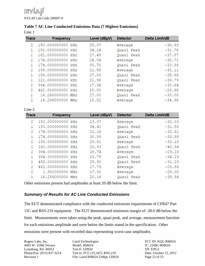
Table 7 AC Line Conducted Emissions Data (7 Highest Emissions)
Line 1
Line 2
Other emissions present had amplitudes at least 20 dB below the limit.
Summary of Results for AC Line Conducted Emissions
The EUT demonstrated compliance with the conducted emissions requirements of CFR47 Part
15C and RSS-210 equipment. The EUT demonstrated minimum margin of -28.0 dB below the
limit. Measurements were taken using the peak, quasi peak, and average, measurement function
for each emissions amplitude and were below the limits stated in the specification. Other
emissions were present with recorded data representing worst-case amplitudes.
NVLAP Lab Code 200087-0
Rogers Labs, Inc. Laird Technologies FCC ID: KQL-RM024
4405 W. 259th Terrace Model: RM024 IC: 2268C-RM024
Louisburg, KS 66053 Test #: 120924 SN: ENG1
Phone/Fax: (913) 837-3214 Test to: FCC (15.247), RSS-210 Date: October 15, 2012
Revision 1 File: Laird RM024 TstRpt 120924 Page 24 of 53
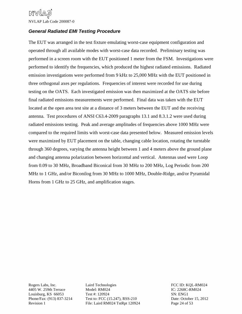
General Radiated EMI Testing Procedure
The EUT was arranged in the test fixture emulating worst-case equipment configuration and
operated through all available modes with worst-case data recorded. Preliminary testing was
performed in a screen room with the EUT positioned 1 meter from the FSM. Investigations were
performed to identify the frequencies, which produced the highest radiated emissions. Radiated
emission investigations were performed from 9 kHz to 25,000 MHz with the EUT positioned in
three orthogonal axes per regulations. Frequencies of interest were recorded for use during
testing on the OATS. Each investigated emission was then maximized at the OATS site before
final radiated emissions measurements were performed. Final data was taken with the EUT
located at the open area test site at a distance of 3 meters between the EUT and the receiving
antenna. Test procedures of ANSI C63.4-2009 paragraphs 13.1 and 8.3.1.2 were used during
radiated emissions testing. Peak and average amplitudes of frequencies above 1000 MHz were
compared to the required limits with worst-case data presented below. Measured emission levels
were maximized by EUT placement on the table, changing cable location, rotating the turntable
through 360 degrees, varying the antenna height between 1 and 4 meters above the ground plane
and changing antenna polarization between horizontal and vertical. Antennas used were Loop
from 0.09 to 30 MHz, Broadband Biconical from 30 MHz to 200 MHz, Log Periodic from 200
MHz to 1 GHz, and/or Biconilog from 30 MHz to 1000 MHz, Double-Ridge, and/or Pyramidal
Horns from 1 GHz to 25 GHz, and amplification stages.

NVLAP Lab Code 200087-0
Rogers Labs, Inc. Laird Technologies FCC ID: KQL-RM024
4405 W. 259th Terrace Model: RM024 IC: 2268C-RM024
Louisburg, KS 66053 Test #: 120924 SN: ENG1
Phone/Fax: (913) 837-3214 Test to: FCC (15.247), RSS-210 Date: October 15, 2012
Revision 1 File: Laird RM024 TstRpt 120924 Page 25 of 53
Table 8 General Radiated Emissions Data (worst-case all antennas)
Frequency in
MHz
Horizontal
Peak
(dBµV/m)
Horizontal
Quasi-Peak
(dBµV/m)
Horizontal
Average
(dBµV/m)
Vertical
Peak
(dBµV/m)
Vertical
Quasi-Peak
(dBµV/m)
Vertical
Average
(dBµV/m)
Limit @ 3m
(dBµV/m)
48.8 37.1 32.0 N/A 35.4 27.6 N/A 40.0
97.6 38.2 34.1 N/A 39.3 37.1 N/A 43.5
102.4 36.6 28.6 N/A 40.9 37.5 N/A 43.5
105.0 37.6 33.7 N/A 34.5 31.7 N/A 43.5
111.7 35.6 28.9 N/A 42.1 36.5 N/A 43.5
114.6 32.9 26.7 N/A 39.0 34.8 N/A 43.5
115.2 33.7 26.5 N/A 38.5 34.0 N/A 43.5
132.1 36.1 32.9 N/A 38.6 35.0 N/A 43.5
165.3 30.2 24.7 N/A 35.1 29.8 N/A 43.5
250.0 42.3 41.2 N/A 39.4 38.2 N/A 46.0
263.8 40.4 37.2 N/A 40.1 36.7 N/A 46.0
325.5 41.1 37.7 N/A 42.5 39.2 N/A 46.0
396.3 44.7 39.6 N/A 43.6 39.3 N/A 46.0
455.7 42.7 40.3 N/A 42.3 39.4 N/A 46.0
660.0 42.2 38.5 N/A 44.4 39.2 N/A 46.0
666.0 46.2 40.6 N/A 45.3 39.9 N/A 46.0
927.3 47.6 39.2 N/A 43.5 37.2 N/A 46.0
932.0 47.6 40.8 N/A 43.9 39.6 N/A 46.0
Other emissions present had amplitudes at least 20 dB below the limit.
Quasi-Peak amplitude emissions are recorded above for frequency range of 30-1000 MHz.
Average amplitude emissions are recorded above for frequency range above 1000 MHz.
Summary of Results for General Radiated Emissions
The EUT demonstrated compliance with the general radiated emissions requirements of CFR47
Part 15.247 and RSS-210. The EUT demonstrated a minimum margin of -4.8 dB below general
radiated emissions requirements. There are no other significantly measurable emissions in the
restricted bands other than those recorded in this report. Other emissions were present with
amplitudes at least 20 dB below the requirements.

NVLAP Lab Code 200087-0
Rogers Labs, Inc. Laird Technologies FCC ID: KQL-RM024
4405 W. 259th Terrace Model: RM024 IC: 2268C-RM024
Louisburg, KS 66053 Test #: 120924 SN: ENG1
Phone/Fax: (913) 837-3214 Test to: FCC (15.247), RSS-210 Date: October 15, 2012
Revision 1 File: Laird RM024 TstRpt 120924 Page 26 of 53
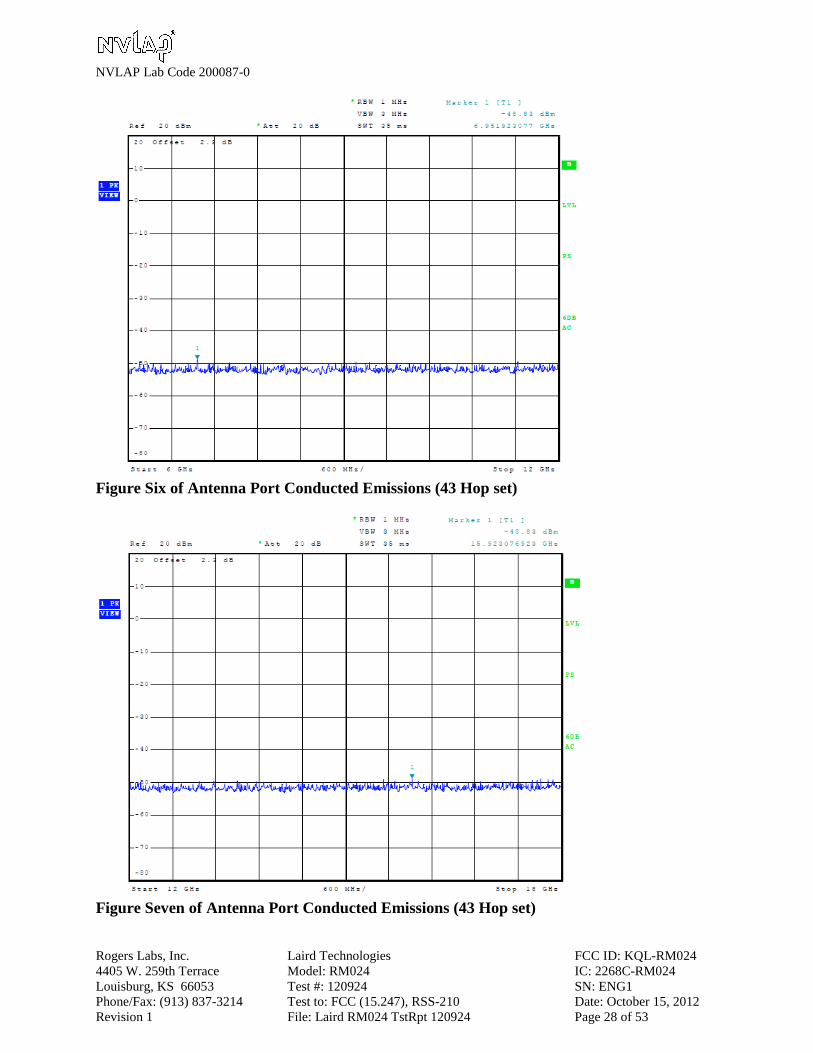
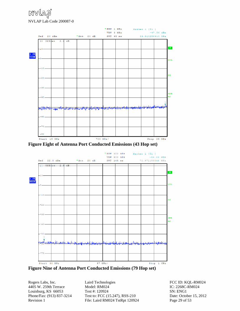
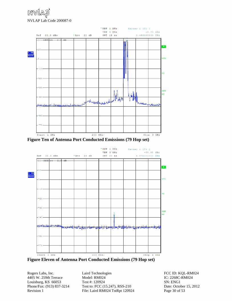
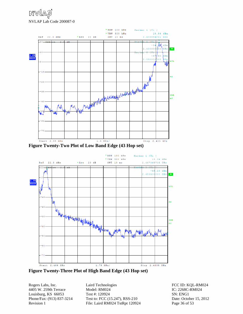
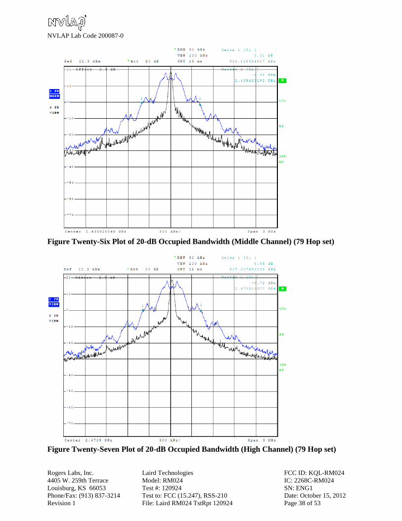
Operation in the Band 2400 – 2483.5 MHz
The power output was measured both at the antenna connection port and at the open area test site at
a three-meter distance with the authorized antenna systems. Harmonic emissions measurement data
presented in tables 10 through 14 include Duty Cycle correction Factor (DCF) reduction of -17.7 dB
(as authorized in 47 CFR paragraph 15.35(b) and RSS –GEN paragraph 4.5). The DCF was
calculated using the absolute maximum transmitter on time (13 mS) over a 100 millisecond period
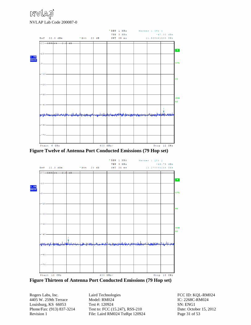
(20log[13/100] = -17.7). Figures three through fourteen represent antenna conducted emissions
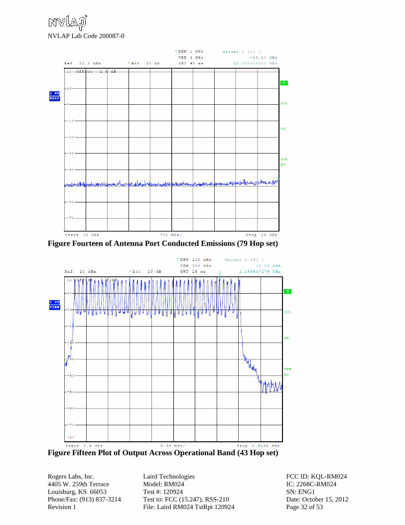
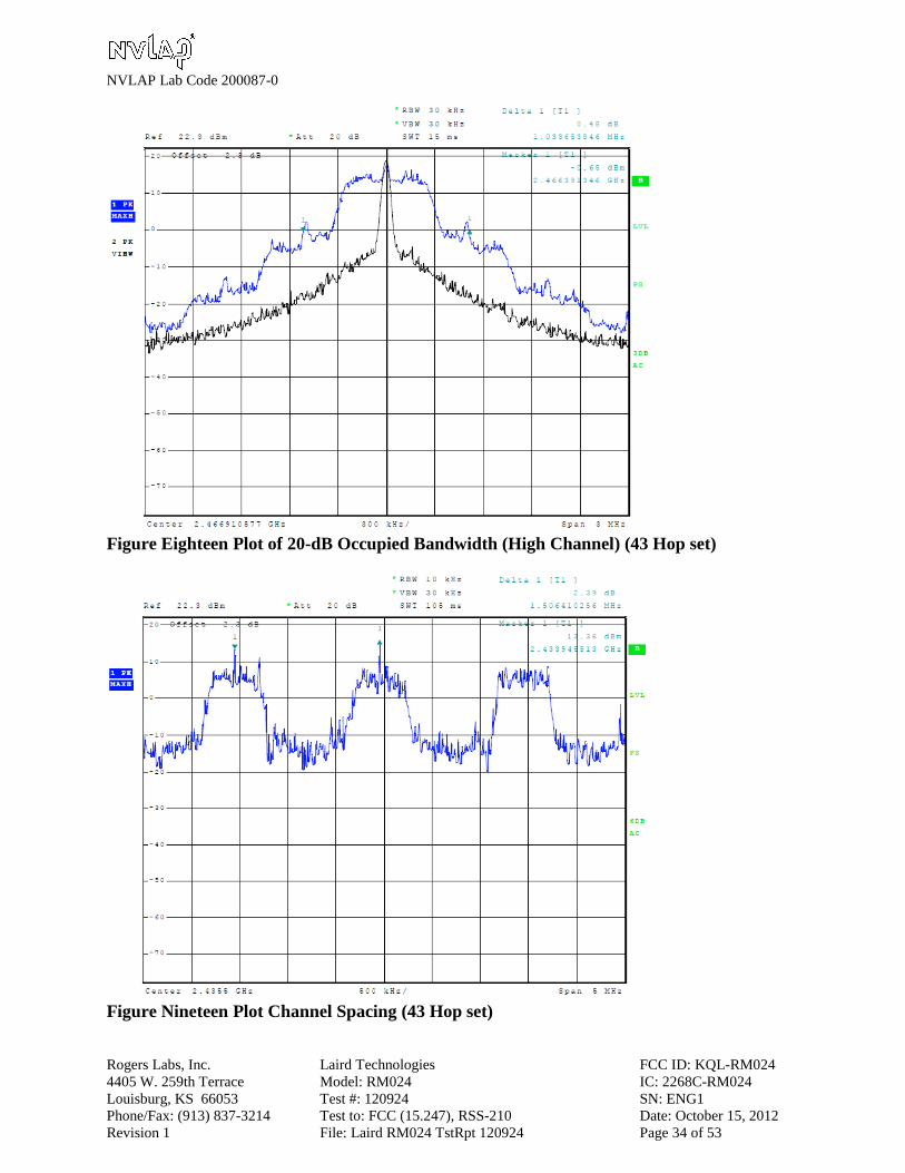
across the frequency spectrum for both the 43 and 79 hopping modes. Figures fifteen through
twenty-three demonstrate compliance of the 43 hop set mode with the FHSS requirements of
15.247(c) and RSS-210. Figures twenty-four through thirty-two demonstrate compliance of the 79
hop set mode with the FHSS requirements of 15.247(c) and RSS-210.
Figure Three of Antenna Port Conducted Emissions (43 Hop set)

NVLAP Lab Code 200087-0
Rogers Labs, Inc. Laird Technologies FCC ID: KQL-RM024
4405 W. 259th Terrace Model: RM024 IC: 2268C-RM024
Louisburg, KS 66053 Test #: 120924 SN: ENG1
Phone/Fax: (913) 837-3214 Test to: FCC (15.247), RSS-210 Date: October 15, 2012
Revision 1 File: Laird RM024 TstRpt 120924 Page 27 of 53
Figure Four of Antenna Port Conducted Emissions (43 Hop set)
Figure Five of Antenna Port Conducted Emissions (43 Hop set)
NVLAP Lab Code 200087-0
Rogers Labs, Inc. Laird Technologies FCC ID: KQL-RM024
4405 W. 259th Terrace Model: RM024 IC: 2268C-RM024
Louisburg, KS 66053 Test #: 120924 SN: ENG1
Phone/Fax: (913) 837-3214 Test to: FCC (15.247), RSS-210 Date: October 15, 2012
Revision 1 File: Laird RM024 TstRpt 120924 Page 28 of 53
Figure Six of Antenna Port Conducted Emissions (43 Hop set)
Figure Seven of Antenna Port Conducted Emissions (43 Hop set)
NVLAP Lab Code 200087-0
Rogers Labs, Inc. Laird Technologies FCC ID: KQL-RM024
4405 W. 259th Terrace Model: RM024 IC: 2268C-RM024
Louisburg, KS 66053 Test #: 120924 SN: ENG1
Phone/Fax: (913) 837-3214 Test to: FCC (15.247), RSS-210 Date: October 15, 2012
Revision 1 File: Laird RM024 TstRpt 120924 Page 29 of 53
Figure Eight of Antenna Port Conducted Emissions (43 Hop set)
Figure Nine of Antenna Port Conducted Emissions (79 Hop set)
NVLAP Lab Code 200087-0
Rogers Labs, Inc. Laird Technologies FCC ID: KQL-RM024
4405 W. 259th Terrace Model: RM024 IC: 2268C-RM024
Louisburg, KS 66053 Test #: 120924 SN: ENG1
Phone/Fax: (913) 837-3214 Test to: FCC (15.247), RSS-210 Date: October 15, 2012
Revision 1 File: Laird RM024 TstRpt 120924 Page 30 of 53
Figure Ten of Antenna Port Conducted Emissions (79 Hop set)
Figure Eleven of Antenna Port Conducted Emissions (79 Hop set)
NVLAP Lab Code 200087-0
Rogers Labs, Inc. Laird Technologies FCC ID: KQL-RM024
4405 W. 259th Terrace Model: RM024 IC: 2268C-RM024
Louisburg, KS 66053 Test #: 120924 SN: ENG1
Phone/Fax: (913) 837-3214 Test to: FCC (15.247), RSS-210 Date: October 15, 2012
Revision 1 File: Laird RM024 TstRpt 120924 Page 31 of 53
Figure Twelve of Antenna Port Conducted Emissions (79 Hop set)
Figure Thirteen of Antenna Port Conducted Emissions (79 Hop set)
NVLAP Lab Code 200087-0
Rogers Labs, Inc. Laird Technologies FCC ID: KQL-RM024
4405 W. 259th Terrace Model: RM024 IC: 2268C-RM024
Louisburg, KS 66053 Test #: 120924 SN: ENG1
Phone/Fax: (913) 837-3214 Test to: FCC (15.247), RSS-210 Date: October 15, 2012
Revision 1 File: Laird RM024 TstRpt 120924 Page 32 of 53
Figure Fourteen of Antenna Port Conducted Emissions (79 Hop set)
Figure Fifteen Plot of Output Across Operational Band (43 Hop set)

NVLAP Lab Code 200087-0
Rogers Labs, Inc. Laird Technologies FCC ID: KQL-RM024
4405 W. 259th Terrace Model: RM024 IC: 2268C-RM024
Louisburg, KS 66053 Test #: 120924 SN: ENG1
Phone/Fax: (913) 837-3214 Test to: FCC (15.247), RSS-210 Date: October 15, 2012
Revision 1 File: Laird RM024 TstRpt 120924 Page 33 of 53
Figure Sixteen Plot of 20-dB Occupied Bandwidth (Low Channel) (43 Hop set)
Figure Seventeen Plot of 20-dB Occupied Bandwidth (Middle Channel) (43 Hop set)
NVLAP Lab Code 200087-0
Rogers Labs, Inc. Laird Technologies FCC ID: KQL-RM024
4405 W. 259th Terrace Model: RM024 IC: 2268C-RM024
Louisburg, KS 66053 Test #: 120924 SN: ENG1
Phone/Fax: (913) 837-3214 Test to: FCC (15.247), RSS-210 Date: October 15, 2012
Revision 1 File: Laird RM024 TstRpt 120924 Page 34 of 53
Figure Eighteen Plot of 20-dB Occupied Bandwidth (High Channel) (43 Hop set)
Figure Nineteen Plot Channel Spacing (43 Hop set)

NVLAP Lab Code 200087-0
Rogers Labs, Inc. Laird Technologies FCC ID: KQL-RM024
4405 W. 259th Terrace Model: RM024 IC: 2268C-RM024
Louisburg, KS 66053 Test #: 120924 SN: ENG1
Phone/Fax: (913) 837-3214 Test to: FCC (15.247), RSS-210 Date: October 15, 2012
Revision 1 File: Laird RM024 TstRpt 120924 Page 35 of 53
Figure Twenty Plot of Dwell time on Channel (43 Hop set)
Figure Twenty-0ne Plot Channel Occupancy (43 Hop set)
NVLAP Lab Code 200087-0
Rogers Labs, Inc. Laird Technologies FCC ID: KQL-RM024
4405 W. 259th Terrace Model: RM024 IC: 2268C-RM024
Louisburg, KS 66053 Test #: 120924 SN: ENG1
Phone/Fax: (913) 837-3214 Test to: FCC (15.247), RSS-210 Date: October 15, 2012
Revision 1 File: Laird RM024 TstRpt 120924 Page 36 of 53
Figure Twenty-Two Plot of Low Band Edge (43 Hop set)
Figure Twenty-Three Plot of High Band Edge (43 Hop set)

NVLAP Lab Code 200087-0
Rogers Labs, Inc. Laird Technologies FCC ID: KQL-RM024
4405 W. 259th Terrace Model: RM024 IC: 2268C-RM024
Louisburg, KS 66053 Test #: 120924 SN: ENG1
Phone/Fax: (913) 837-3214 Test to: FCC (15.247), RSS-210 Date: October 15, 2012
Revision 1 File: Laird RM024 TstRpt 120924 Page 37 of 53
Figure Twenty-Four Plot of Output Across Operational Band (79 Hop set)
Figure Twenty-Five Plot of 20-dB Occupied Bandwidth (Low Channel) (79 Hop set)
NVLAP Lab Code 200087-0
Rogers Labs, Inc. Laird Technologies FCC ID: KQL-RM024
4405 W. 259th Terrace Model: RM024 IC: 2268C-RM024
Louisburg, KS 66053 Test #: 120924 SN: ENG1
Phone/Fax: (913) 837-3214 Test to: FCC (15.247), RSS-210 Date: October 15, 2012
Revision 1 File: Laird RM024 TstRpt 120924 Page 38 of 53
Figure Twenty-Six Plot of 20-dB Occupied Bandwidth (Middle Channel) (79 Hop set)
Figure Twenty-Seven Plot of 20-dB Occupied Bandwidth (High Channel) (79 Hop set)

NVLAP Lab Code 200087-0
Rogers Labs, Inc. Laird Technologies FCC ID: KQL-RM024
4405 W. 259th Terrace Model: RM024 IC: 2268C-RM024
Louisburg, KS 66053 Test #: 120924 SN: ENG1
Phone/Fax: (913) 837-3214 Test to: FCC (15.247), RSS-210 Date: October 15, 2012
Revision 1 File: Laird RM024 TstRpt 120924 Page 39 of 53
Figure Twenty-Eight Plot Channel Spacing (79 Hop set)
Figure Twenty-Nine Plot of Dwell time on Channel (79 Hop set)

NVLAP Lab Code 200087-0
Rogers Labs, Inc. Laird Technologies FCC ID: KQL-RM024
4405 W. 259th Terrace Model: RM024 IC: 2268C-RM024
Louisburg, KS 66053 Test #: 120924 SN: ENG1
Phone/Fax: (913) 837-3214 Test to: FCC (15.247), RSS-210 Date: October 15, 2012
Revision 1 File: Laird RM024 TstRpt 120924 Page 40 of 53
Figure Thirty Plot Channel Occupancy (79 Hop set)
Figure Thirty-One Plot of Low Band Edge (79 Hop set)

NVLAP Lab Code 200087-0
Rogers Labs, Inc. Laird Technologies FCC ID: KQL-RM024
4405 W. 259th Terrace Model: RM024 IC: 2268C-RM024
Louisburg, KS 66053 Test #: 120924 SN: ENG1
Phone/Fax: (913) 837-3214 Test to: FCC (15.247), RSS-210 Date: October 15, 2012
Revision 1 File: Laird RM024 TstRpt 120924 Page 41 of 53
Figure Thirty -Two Plot of High Band Edge (79 Hop set)
Transmitter Emissions Data
Table 9 Transmitter Antenna Conducted Emissions Data
The antenna conducted output power and 20-dB bandwidth were measured while operating in
available modes for the lowest, middle and highest available channels. The data reported below
represents the worst-case operational conditions.
Operational
Mode
Frequency
MHz
Antenna Conducted
Output Power dBm
Antenna Conducted
Output Power mW
Occupied
Bandwidth kHz
43 Hop Set 2404.00 20.33 107.9 1,043.3
43 Hop Set 2435.47 20.23 105.4 1,072.1
43 Hop Set 2466.93 20.28 106.7 1,033.6
79 Hop Set 2400.76 20.38 109.1 841.3
79 Hop Set 2435.85 20.24 105.7 822.1
79 Hop Set 2479.94 20.27 106.4 817.4

NVLAP Lab Code 200087-0
Rogers Labs, Inc. Laird Technologies FCC ID: KQL-RM024
4405 W. 259th Terrace Model: RM024 IC: 2268C-RM024
Louisburg, KS 66053 Test #: 120924 SN: ENG1
Phone/Fax: (913) 837-3214 Test to: FCC (15.247), RSS-210 Date: October 15, 2012
Revision 1 File: Laird RM024 TstRpt 120924 Page 42 of 53
Table 10 Transmitter Radiated Emission Data (2 dBi Chip Antenna)
Frequency in
MHz
Horizontal
Peak
(dBµV/m)
Horizontal
Quasi-Peak
(dBµV/m)
Horizontal
Average
(dBµV/m)
Vertical
Peak
(dBµV/m)
Vertical
Quasi-Peak
(dBµV/m)
Vertical
Average
(dBµV/m)
Limit @ 3m
(dBµV/m)
2400.7 105.6 N/A 99.5 111.8 N/A 106.6 --
4801.4 33.0 N/A 20.7 36.3 N/A 26.2 54
7202.1 29.6 N/A 16.9 30.6 N/A 17.7 54
9602.8 36.7 N/A 27.3 34.3 N/A 24.4 54
12003.5 33.5 N/A 20.8 32.6 N/A 20.2 54
14404.2 35.2 N/A 22.2 34.7 N/A 22.2 54
16804.9 33.4 N/A 20.8 33.4 N/A 20.8 54
2435.8 104.9 N/A 99.6 112.1 N/A 106.0 --
4871.6 32.9 N/A 20.5 35.6 N/A 25.2 54
7307.4 29.3 N/A 16.7 30.4 N/A 19.0 54
9743.2 36.8 N/A 27.5 33.5 N/A 22.9 54
12179.0 32.8 N/A 20.5 31.3 N/A 18.5 54
14614.8 33.7 N/A 21.4 33.9 N/A 21.4 54
17050.6 34.7 N/A 21.1 34.7 N/A 21.2 54
2470.9 104.2 N/A 98.9 111.9 N/A 106.7 --
4941.8 32.7 N/A 20.2 34.4 N/A 23.1 54
7412.7 28.4 N/A 15.4 30.7 N/A 19.4 54
9883.6 36.9 N/A 27.2 35.6 N/A 25.9 54
12354.5 31.8 N/A 19.6 32.5 N/A 18.9 54
14825.4 35.7 N/A 22.9 35.7 N/A 22.7 54
17296.3 33.4 N/A 21.3 34.0 N/A 21.3 54
Other emissions present had amplitudes at least 20 dB below the limit.
Quasi-Peak amplitude emissions are recorded above for frequency range of 30-1000 MHz.
Average amplitude emissions are recorded above for frequency range above 1000 MHz.
NVLAP Lab Code 200087-0
Rogers Labs, Inc. Laird Technologies FCC ID: KQL-RM024
4405 W. 259th Terrace Model: RM024 IC: 2268C-RM024
Louisburg, KS 66053 Test #: 120924 SN: ENG1
Phone/Fax: (913) 837-3214 Test to: FCC (15.247), RSS-210 Date: October 15, 2012
Revision 1 File: Laird RM024 TstRpt 120924 Page 43 of 53
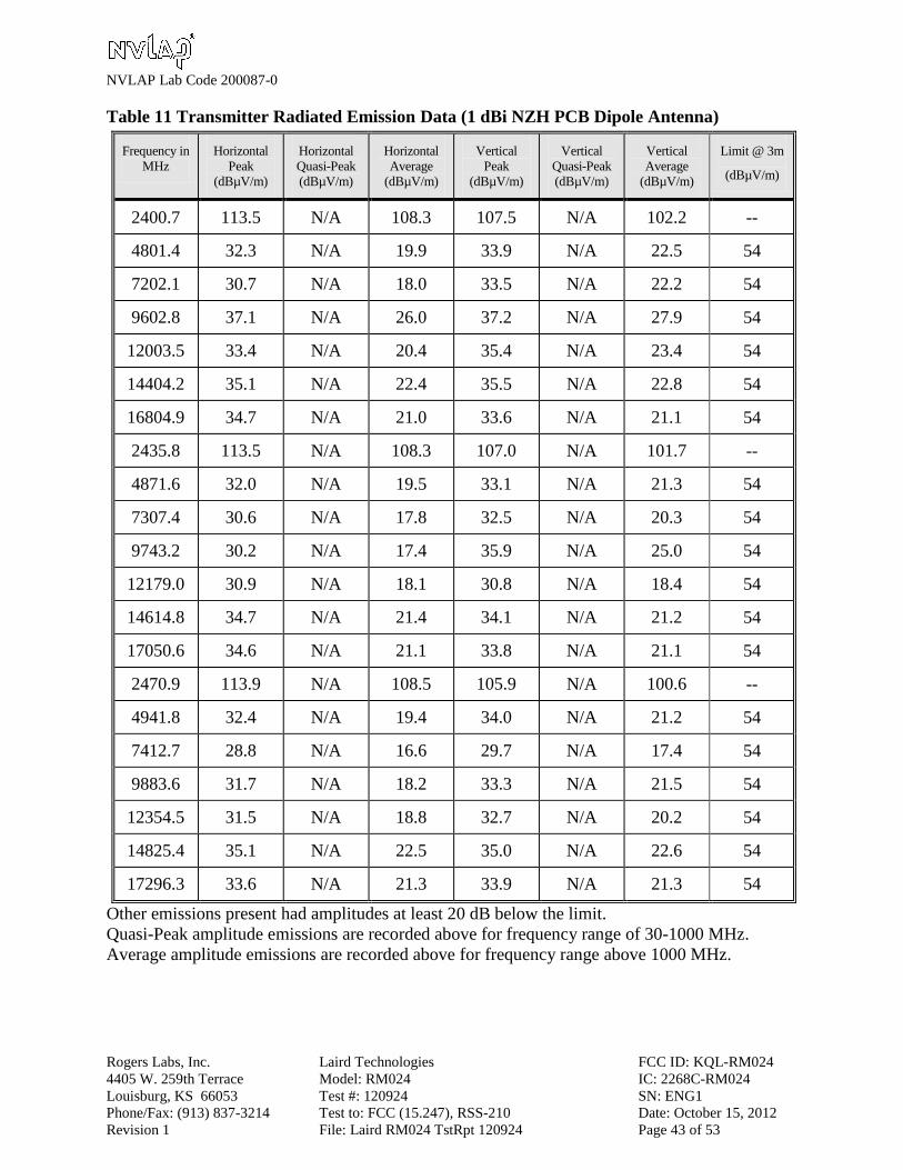
Table 11 Transmitter Radiated Emission Data (1 dBi NZH PCB Dipole Antenna)
Frequency in
MHz
Horizontal
Peak
(dBµV/m)
Horizontal
Quasi-Peak
(dBµV/m)
Horizontal
Average
(dBµV/m)
Vertical
Peak
(dBµV/m)
Vertical
Quasi-Peak
(dBµV/m)
Vertical
Average
(dBµV/m)
Limit @ 3m
(dBµV/m)
2400.7 113.5 N/A 108.3 107.5 N/A 102.2 --
4801.4 32.3 N/A 19.9 33.9 N/A 22.5 54
7202.1 30.7 N/A 18.0 33.5 N/A 22.2 54
9602.8 37.1 N/A 26.0 37.2 N/A 27.9 54
12003.5 33.4 N/A 20.4 35.4 N/A 23.4 54
14404.2 35.1 N/A 22.4 35.5 N/A 22.8 54
16804.9 34.7 N/A 21.0 33.6 N/A 21.1 54
2435.8 113.5 N/A 108.3 107.0 N/A 101.7 --
4871.6 32.0 N/A 19.5 33.1 N/A 21.3 54
7307.4 30.6 N/A 17.8 32.5 N/A 20.3 54
9743.2 30.2 N/A 17.4 35.9 N/A 25.0 54
12179.0 30.9 N/A 18.1 30.8 N/A 18.4 54
14614.8 34.7 N/A 21.4 34.1 N/A 21.2 54
17050.6 34.6 N/A 21.1 33.8 N/A 21.1 54
2470.9 113.9 N/A 108.5 105.9 N/A 100.6 --
4941.8 32.4 N/A 19.4 34.0 N/A 21.2 54
7412.7 28.8 N/A 16.6 29.7 N/A 17.4 54
9883.6 31.7 N/A 18.2 33.3 N/A 21.5 54
12354.5 31.5 N/A 18.8 32.7 N/A 20.2 54
14825.4 35.1 N/A 22.5 35.0 N/A 22.6 54
17296.3 33.6 N/A 21.3 33.9 N/A 21.3 54
Other emissions present had amplitudes at least 20 dB below the limit.
Quasi-Peak amplitude emissions are recorded above for frequency range of 30-1000 MHz.
Average amplitude emissions are recorded above for frequency range above 1000 MHz.

NVLAP Lab Code 200087-0
Rogers Labs, Inc. Laird Technologies FCC ID: KQL-RM024
4405 W. 259th Terrace Model: RM024 IC: 2268C-RM024
Louisburg, KS 66053 Test #: 120924 SN: ENG1
Phone/Fax: (913) 837-3214 Test to: FCC (15.247), RSS-210 Date: October 15, 2012
Revision 1 File: Laird RM024 TstRpt 120924 Page 44 of 53
Table 12 Transmitter Radiated Emission Data (5 dBi Dipole Antenna)
Frequency in
MHz
Horizontal
Peak
(dBµV/m)
Horizontal
Quasi-Peak
(dBµV/m)
Horizontal
Average
(dBµV/m)
Vertical
Peak
(dBµV/m)
Vertical
Quasi-Peak
(dBµV/m)
Vertical
Average
(dBµV/m)
Limit @ 3m
(dBµV/m)
2400.7 106.6 N/A 101.4 115.4 N/A 110.2 --
4801.4 33.1 N/A 21.0 36.3 N/A 25.4 54
7202.1 30.7 N/A 17.2 32.0 N/A 20.5 54
9602.8 35.7 N/A 23.7 39.0 N/A 29.9 54
12003.5 33.4 N/A 20.8 36.6 N/A 24.2 54
14404.2 35.5 N/A 22.4 35.1 N/A 22.5 54
16804.9 33.3 N/A 21.1 33.3 N/A 21.1 54
2435.8 107.2 N/A 102.0 116.0 N/A 110.8 --
4871.6 32.2 N/A 19.9 34.3 N/A 23.4 54
7307.4 31.2 N/A 18.8 30.5 N/A 17.7 54
9743.2 37.1 N/A 24.3 35.6 N/A 23.8 54
12179.0 30.4 N/A 18.3 35.3 N/A 23.5 54
14614.8 34.0 N/A 21.4 35.4 N/A 22.5 54
17050.6 34.2 N/A 21.0 33.2 N/A 21.0 54
2470.9 107.5 N/A 102.2 116.5 N/A 111.2 --
4941.8 33.5 N/A 20.7 35.9 N/A 25.2 54
7412.7 29.5 N/A 17.2 29.7 N/A 17.6 54
9883.6 33.9 N/A 21.4 35.3 N/A 23.3 54
12354.5 33.2 N/A 19.9 35.3 N/A 23.9 54
14825.4 35.6 N/A 22.7 35.2 N/A 22.9 54
17296.3 34.5 N/A 21.2 34.2 N/A 21.3 54
Other emissions present had amplitudes at least 20 dB below the limit.
Quasi-Peak amplitude emissions are recorded above for frequency range of 30-1000 MHz.
Average amplitude emissions are recorded above for frequency range above 1000 MHz.

NVLAP Lab Code 200087-0
Rogers Labs, Inc. Laird Technologies FCC ID: KQL-RM024
4405 W. 259th Terrace Model: RM024 IC: 2268C-RM024
Louisburg, KS 66053 Test #: 120924 SN: ENG1
Phone/Fax: (913) 837-3214 Test to: FCC (15.247), RSS-210 Date: October 15, 2012
Revision 1 File: Laird RM024 TstRpt 120924 Page 45 of 53
Table 13 Transmitter Radiated Emission Data (6 dBi Omni Antenna)
Frequency in
MHz
Horizontal
Peak
(dBµV/m)
Horizontal
Quasi-Peak
(dBµV/m)
Horizontal
Average
(dBµV/m)
Vertical
Peak
(dBµV/m)
Vertical
Quasi-Peak
(dBµV/m)
Vertical
Average
(dBµV/m)
Limit @ 3m
(dBµV/m)
2400.7 98.4 N/A 93.2 117.0 N/A 111.9 --
4801.4 32.5 N/A 20.2 35.3 N/A 25.2 54
7202.1 29.7 N/A 17.4 31.3 N/A 19.2 54
9602.8 36.4 N/A 23.9 36.4 N/A 25.9 54
12003.5 32.9 N/A 20.2 34.8 N/A 22.9 54
14404.2 35.1 N/A 22.2 34.9 N/A 22.5 54
16804.9 33.8 N/A 21.0 34.4 N/A 21.0 54
2435.8 96.4 N/A 90.9 117.5 N/A 112.3 --
4871.6 32.4 N/A 20.3 33.6 N/A 21.9 54
7307.4 27.5 N/A 15.4 29.2 N/A 16.7 54
9743.2 33.7 N/A 20.9 37.7 N/A 25.3 54
12179.0 32.3 N/A 19.1 31.3 N/A 19.1 54
14614.8 34.6 N/A 21.3 34.2 N/A 21.2 54
17050.6 33.6 N/A 21.1 34.1 N/A 21.1 54
2470.9 96.0 N/A 90.8 117.4 N/A 111.9 --
4941.8 32.8 N/A 20.7 34.4 N/A 23.0 54
7412.7 27.3 N/A 14.8 28.0 N/A 14.7 54
9883.6 32.7 N/A 20.0 38.4 N/A 27.5 54
12354.5 30.8 N/A 18.8 33.4 N/A 20.2 54
14825.4 35.7 N/A 22.6 34.6 N/A 22.6 54
17296.3 34.1 N/A 21.2 34.3 N/A 21.2 54
Other emissions present had amplitudes at least 20 dB below the limit.
Quasi-Peak amplitude emissions are recorded above for frequency range of 30-1000 MHz.
Average amplitude emissions are recorded above for frequency range above 1000 MHz.
NVLAP Lab Code 200087-0
Rogers Labs, Inc. Laird Technologies FCC ID: KQL-RM024
4405 W. 259th Terrace Model: RM024 IC: 2268C-RM024
Louisburg, KS 66053 Test #: 120924 SN: ENG1
Phone/Fax: (913) 837-3214 Test to: FCC (15.247), RSS-210 Date: October 15, 2012
Revision 1 File: Laird RM024 TstRpt 120924 Page 46 of 53
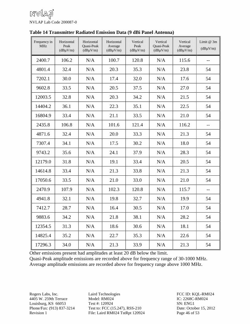
Table 14 Transmitter Radiated Emission Data (9 dBi Panel Antenna)
Frequency in
MHz
Horizontal
Peak
(dBµV/m)
Horizontal
Quasi-Peak
(dBµV/m)
Horizontal
Average
(dBµV/m)
Vertical
Peak
(dBµV/m)
Vertical
Quasi-Peak
(dBµV/m)
Vertical
Average
(dBµV/m)
Limit @ 3m
(dBµV/m)
2400.7 106.2 N/A 100.7 120.8 N/A 115.6 --
4801.4 32.4 N/A 20.3 35.3 N/A 23.8 54
7202.1 30.0 N/A 17.4 32.0 N/A 17.6 54
9602.8 33.5 N/A 20.5 37.5 N/A 27.0 54
12003.5 32.8 N/A 20.3 34.2 N/A 21.5 54
14404.2 36.1 N/A 22.3 35.1 N/A 22.5 54
16804.9 33.4 N/A 21.1 33.5 N/A 21.0 54
2435.8 106.8 N/A 101.6 121.4 N/A 116.2 --
4871.6 32.4 N/A 20.0 33.3 N/A 21.3 54
7307.4 34.1 N/A 17.5 30.2 N/A 18.0 54
9743.2 35.6 N/A 24.1 37.9 N/A 28.3 54
12179.0 31.8 N/A 19.1 33.4 N/A 20.5 54
14614.8 33.4 N/A 21.3 33.8 N/A 21.3 54
17050.6 33.5 N/A 21.0 33.0 N/A 21.0 54
2470.9 107.9 N/A 102.3 120.8 N/A 115.7 --
4941.8 32.1 N/A 19.8 32.7 N/A 19.9 54
7412.7 28.7 N/A 16.4 30.5 N/A 17.0 54
9883.6 34.2 N/A 21.8 38.1 N/A 28.2 54
12354.5 31.3 N/A 18.6 30.6 N/A 18.1 54
14825.4 35.2 N/A 22.7 35.3 N/A 22.6 54
17296.3 34.0 N/A 21.3 33.9 N/A 21.3 54
Other emissions present had amplitudes at least 20 dB below the limit.
Quasi-Peak amplitude emissions are recorded above for frequency range of 30-1000 MHz.
Average amplitude emissions are recorded above for frequency range above 1000 MHz.
NVLAP Lab Code 200087-0
Rogers Labs, Inc. Laird Technologies FCC ID: KQL-RM024
4405 W. 259th Terrace Model: RM024 IC: 2268C-RM024
Louisburg, KS 66053 Test #: 120924 SN: ENG1
Phone/Fax: (913) 837-3214 Test to: FCC (15.247), RSS-210 Date: October 15, 2012
Revision 1 File: Laird RM024 TstRpt 120924 Page 47 of 53
Summary of Results for Radiated Emissions of Intentional Radiator
The EUT demonstrated antenna conducted output power of 109.1 Milliwatts (0.11 Watts) at
antenna port. The EUT presented in compliance with the radiated emissions requirements of
CFR47 Part 15.247 and RSS-210 with highest radiated emission level measured of 116.2
dBµV/m. The EUT demonstrated a minimum margin of -24.1 dB below the harmonic emissions
requirements. The EUT demonstrated a minimum margin of -22.0 dB below the emissions
requirements for restricted bands (transmitter emissions). The EUT support equipment
demonstrated a minimum margin of -4.8 dB below the emissions requirements for restricted
bands (general emissions of support equipment). The EUT tested was observed in compliance
with the radiated emissions requirements of CFR47 Part 15.247 and RSS-210 Intentional
Radiators. There were no other significantly measurable emissions observed in restricted bands
other than those recorded in this report. Other emissions were present with amplitudes at least
20 dB below the requirements. The EUT demonstrated compliance with the specifications of
CFR47 15.247 and RSS-210. There were no deviations or exceptions to the requirements.
NVLAP Lab Code 200087-0
Rogers Labs, Inc. Laird Technologies FCC ID: KQL-RM024
4405 W. 259th Terrace Model: RM024 IC: 2268C-RM024
Louisburg, KS 66053 Test #: 120924 SN: ENG1
Phone/Fax: (913) 837-3214 Test to: FCC (15.247), RSS-210 Date: October 15, 2012
Revision 1 File: Laird RM024 TstRpt 120924 Page 48 of 53
Annex
Annex A Measurement Uncertainty Calculations
Annex B Rogers Labs Test Equipment List
Annex C Rogers Qualifications
Annex D FCC Site Registration Letter
Annex E Industry Canada Site Registration Letter
NVLAP Lab Code 200087-0
Rogers Labs, Inc. Laird Technologies FCC ID: KQL-RM024
4405 W. 259th Terrace Model: RM024 IC: 2268C-RM024
Louisburg, KS 66053 Test #: 120924 SN: ENG1
Phone/Fax: (913) 837-3214 Test to: FCC (15.247), RSS-210 Date: October 15, 2012
Revision 1 File: Laird RM024 TstRpt 120924 Page 49 of 53
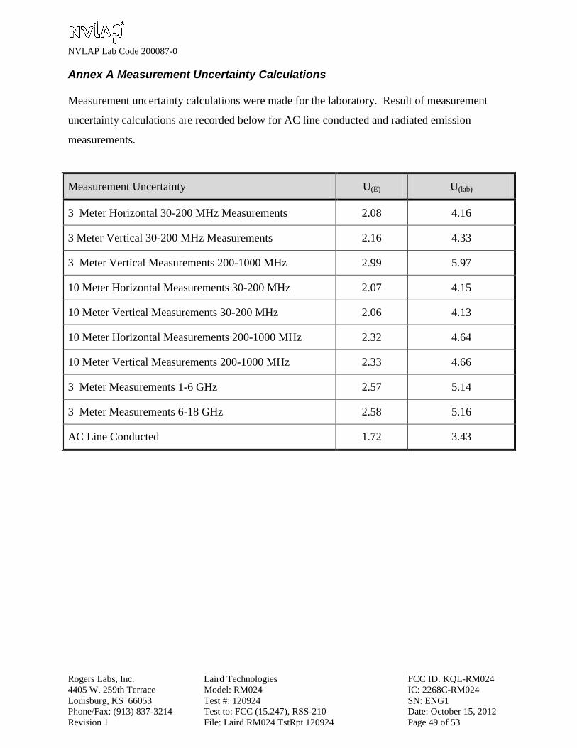
Annex A Measurement Uncertainty Calculations
Measurement uncertainty calculations were made for the laboratory. Result of measurement
uncertainty calculations are recorded below for AC line conducted and radiated emission
measurements.
Measurement Uncertainty U(E) U(lab)
3 Meter Horizontal 30-200 MHz Measurements 2.08 4.16
3 Meter Vertical 30-200 MHz Measurements 2.16 4.33
3 Meter Vertical Measurements 200-1000 MHz 2.99 5.97
10 Meter Horizontal Measurements 30-200 MHz 2.07 4.15
10 Meter Vertical Measurements 30-200 MHz 2.06 4.13
10 Meter Horizontal Measurements 200-1000 MHz 2.32 4.64
10 Meter Vertical Measurements 200-1000 MHz 2.33 4.66
3 Meter Measurements 1-6 GHz 2.57 5.14
3 Meter Measurements 6-18 GHz 2.58 5.16
AC Line Conducted 1.72 3.43
NVLAP Lab Code 200087-0
Rogers Labs, Inc. Laird Technologies FCC ID: KQL-RM024
4405 W. 259th Terrace Model: RM024 IC: 2268C-RM024
Louisburg, KS 66053 Test #: 120924 SN: ENG1
Phone/Fax: (913) 837-3214 Test to: FCC (15.247), RSS-210 Date: October 15, 2012
Revision 1 File: Laird RM024 TstRpt 120924 Page 50 of 53
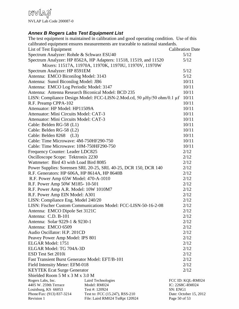
Annex B Rogers Labs Test Equipment List The test equipment is maintained in calibration and good operating condition. Use of this
calibrated equipment ensures measurements are traceable to national standards.
List of Test Equipment Calibration Date
Spectrum Analyzer: Rohde & Schwarz ESU40 5/12
Spectrum Analyzer: HP 8562A, HP Adapters: 11518, 11519, and 11520 5/12
Mixers: 11517A, 11970A, 11970K, 11970U, 11970V, 11970W
Spectrum Analyzer: HP 8591EM 5/12
Antenna: EMCO Biconilog Model: 3143 5/12
Antenna: Sunol Biconilog Model: JB6 10/11
Antenna: EMCO Log Periodic Model: 3147 10/11
Antenna: Antenna Research Biconical Model: BCD 235 10/11
LISN: Compliance Design Model: FCC-LISN-2.Mod.cd, 50 μHy/50 ohm/0.1 µf 10/11
R.F. Preamp CPPA-102 10/11
Attenuator: HP Model: HP11509A 10/11
Attenuator: Mini Circuits Model: CAT-3 10/11
Attenuator: Mini Circuits Model: CAT-3 10/11
Cable: Belden RG-58 (L1) 10/11
Cable: Belden RG-58 (L2) 10/11
Cable: Belden 8268 (L3) 10/11
Cable: Time Microwave: 4M-750HF290-750 10/11
Cable: Time Microwave: 10M-750HF290-750 10/11
Frequency Counter: Leader LDC825 2/12
Oscilloscope Scope: Tektronix 2230 2/12
Wattmeter: Bird 43 with Load Bird 8085 2/12
Power Supplies: Sorensen SRL 20-25, SRL 40-25, DCR 150, DCR 140 2/12
R.F. Generators: HP 606A, HP 8614A, HP 8640B 2/12
R.F. Power Amp 65W Model: 470-A-1010 2/12
R.F. Power Amp 50W M185- 10-501 2/12
R.F. Power Amp A.R. Model: 10W 1010M7 2/12
R.F. Power Amp EIN Model: A301 2/12
LISN: Compliance Eng. Model 240/20 2/12
LISN: Fischer Custom Communications Model: FCC-LISN-50-16-2-08 2/12
Antenna: EMCO Dipole Set 3121C 2/12
Antenna: C.D. B-101 2/12
Antenna: Solar 9229-1 & 9230-1 2/12
Antenna: EMCO 6509 2/12
Audio Oscillator: H.P. 201CD 2/12
Peavey Power Amp Model: IPS 801 2/12
ELGAR Model: 1751 2/12
ELGAR Model: TG 704A-3D 2/12
ESD Test Set 2010i 2/12
Fast Transient Burst Generator Model: EFT/B-101 2/12
Field Intensity Meter: EFM-018 2/12
KEYTEK Ecat Surge Generator 2/12
Shielded Room 5 M x 3 M x 3.0 M
NVLAP Lab Code 200087-0
Rogers Labs, Inc. Laird Technologies FCC ID: KQL-RM024
4405 W. 259th Terrace Model: RM024 IC: 2268C-RM024
Louisburg, KS 66053 Test #: 120924 SN: ENG1
Phone/Fax: (913) 837-3214 Test to: FCC (15.247), RSS-210 Date: October 15, 2012
Revision 1 File: Laird RM024 TstRpt 120924 Page 51 of 53
Annex C Rogers Qualifications
Scot D. Rogers, Engineer
Rogers Labs, Inc.
Mr. Rogers has approximately 17 years’ experience in the field of electronics. Engineering
experience includes six years in the automated controls industry and remaining years working
with the design, development and testing of radio communications and electronic equipment.
Positions Held
Systems Engineer: A/C Controls Mfg. Co., Inc. 6 Years
Electrical Engineer: Rogers Consulting Labs, Inc. 5 Years
Electrical Engineer: Rogers Labs, Inc. Current
Educational Background
1) Bachelor of Science Degree in Electrical Engineering from Kansas State University.
2) Bachelor of Science Degree in Business Administration Kansas State University.
3) Several Specialized Training courses and seminars pertaining to Microprocessors and
Software programming.
Scot D. Rogers
NVLAP Lab Code 200087-0
Rogers Labs, Inc. Laird Technologies FCC ID: KQL-RM024
4405 W. 259th Terrace Model: RM024 IC: 2268C-RM024
Louisburg, KS 66053 Test #: 120924 SN: ENG1
Phone/Fax: (913) 837-3214 Test to: FCC (15.247), RSS-210 Date: October 15, 2012
Revision 1 File: Laird RM024 TstRpt 120924 Page 52 of 53
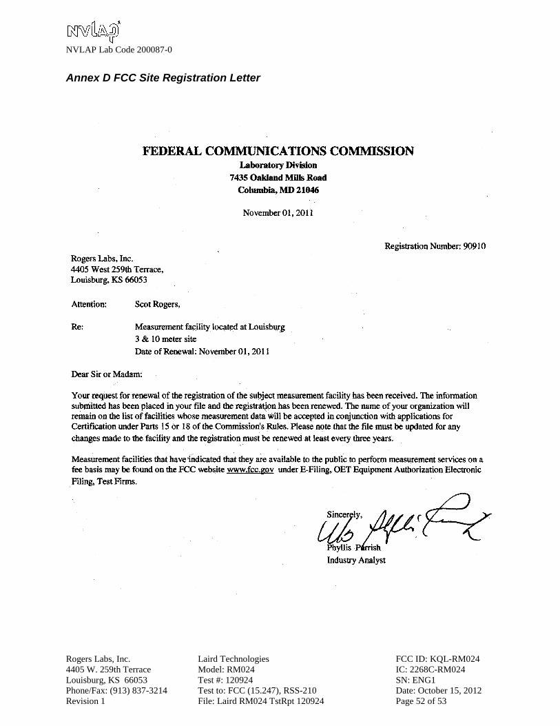
Annex D FCC Site Registration Letter

NVLAP Lab Code 200087-0
Rogers Labs, Inc. Laird Technologies FCC ID: KQL-RM024
4405 W. 259th Terrace Model: RM024 IC: 2268C-RM024
Louisburg, KS 66053 Test #: 120924 SN: ENG1
Phone/Fax: (913) 837-3214 Test to: FCC (15.247), RSS-210 Date: October 15, 2012
Revision 1 File: Laird RM024 TstRpt 120924 Page 53 of 53
Annex E Industry Canada Site Registration Letter