NVIC 10-99 9/10/99 NAVIGATION AND VESSEL ... Documents/5p/5ps...Enclosure (1) to NVIC 10-99...
70
Commandant United States Coast Guard 2100 Second St. S.W. W ashington, DC 20593 Staff Symbol: (G-MSE-4) Phone: (202) 267-1444 COMDTPUB P16700.4 NVIC 10-99 9/10/99 NAVIGATION AND VESSEL INSPECTION CIRCULAR NO. 10-99 Subj: INTERPRETATIONS OF SOLAS CHAPTER II-2 1. PURPOSE. This Circular calls attention to “Interpretations of Vague Expressions and Other Vague Wording in SOLAS Chapter II-2”, as approved by the International Maritime Organization (IMO), Maritime Safety Committee, as MSC/Circ.847. The interpretations contained in MSC/Circ.847 should be used as guidance when applying relevant provisions of SOLAS Chapter II-2 to fire protection construction, arrangements, and equipment to be installed on board ships on or after 14 May 1998, in order to fulfill the requirements of the 1974 SOLAS Convention. 2. DIRECTIVES AFFECTED. None. 3. BACKGROUND. a. The IMO’s Subcommittee on Fire Protection, at its 42 nd session (8-12 December 1997), completed a multi-year effort to develop a set of unified interpretations, with a view to ensuring uniform application of the requirements of SOLAS Chapter II-2 containing vague expressions such as “to the satisfaction of the Administration” or other vague wording which is open to diverging interpretations. The United States delegation to the Subcommittee on Fire Protection was very active in the development of these interpretations. b. The IMO’s Maritime Safety Committee, at its 69 th session (11-20 May 1998), approved the set of interpretations to SOLAS Chapter II-2 as MSC/Circ.847, “Interpretations of Vague Expressions and Other Vague Wording in SOLAS Chapter II-2.” c. The IMO’s Subcommittee on Fire Protection, at its 43 rd session (11-15 January 1999), agreed to various minor editorial corrections to MSC/Circ.847 (as listed in IMO documents FP 43/9 and FP 43/9/1). Although the IMO Secretariat will issue these corrections in due course, Commandant (G-MSE-4) has included them in the MSC/Circ.847 attached to this Circular. 4. DISCUSSION. The interpretations in MSC/Circ.847 should be used as guidance when applying the relevant provisions of SOLAS Chapter II-2 to U.S. flag or foreign flag vessels. These interpretations are clarifications only and are not intended to amend SOLAS
Transcript of NVIC 10-99 9/10/99 NAVIGATION AND VESSEL ... Documents/5p/5ps...Enclosure (1) to NVIC 10-99...

CommandantUnited States Coast Guard
2100 Second St. S.W.Washington, DC 20593Staff Symbol: (G-MSE-4)Phone: (202) 267-1444
COMDTPUB P16700.4NVIC 10-999/10/99
NAVIGATION AND VESSEL INSPECTION CIRCULAR NO. 10-99
Subj: INTERPRETATIONS OF SOLAS CHAPTER II-2
1. PURPOSE. This Circular calls attention to “Interpretations of Vague Expressions and OtherVague Wording in SOLAS Chapter II-2”, as approved by the International MaritimeOrganization (IMO), Maritime Safety Committee, as MSC/Circ.847. The interpretationscontained in MSC/Circ.847 should be used as guidance when applying relevant provisions ofSOLAS Chapter II-2 to fire protection construction, arrangements, and equipment to beinstalled on board ships on or after 14 May 1998, in order to fulfill the requirements of the1974 SOLAS Convention.
2. DIRECTIVES AFFECTED. None.
3. BACKGROUND.
a. The IMO’s Subcommittee on Fire Protection, at its 42nd session (8-12 December 1997),completed a multi-year effort to develop a set of unified interpretations, with a view toensuring uniform application of the requirements of SOLAS Chapter II-2 containing vagueexpressions such as “to the satisfaction of the Administration” or other vague wordingwhich is open to diverging interpretations. The United States delegation to theSubcommittee on Fire Protection was very active in the development of theseinterpretations.
b. The IMO’s Maritime Safety Committee, at its 69th session (11-20 May 1998), approvedthe set of interpretations to SOLAS Chapter II-2 as MSC/Circ.847, “Interpretations ofVague Expressions and Other Vague Wording in SOLAS Chapter II-2.”
c. The IMO’s Subcommittee on Fire Protection, at its 43rd session (11-15 January 1999),agreed to various minor editorial corrections to MSC/Circ.847 (as listed in IMOdocuments FP 43/9 and FP 43/9/1). Although the IMO Secretariat will issue thesecorrections in due course, Commandant (G-MSE-4) has included them in theMSC/Circ.847 attached to this Circular.
4. DISCUSSION. The interpretations in MSC/Circ.847 should be used as guidance whenapplying the relevant provisions of SOLAS Chapter II-2 to U.S. flag or foreign flag vessels.These interpretations are clarifications only and are not intended to amend SOLAS

regulations. They are intended to serve as uniform explanations of practices used byAdministrations to comply with the intent of the regulations. These interpretations are notretroactive, but apply to construction, arrangements, and equipment to be installed on boardships on or after 14 May 1998.
5. ACTION.
a. The Commanding Officer, Marine Safety Center and Officers in Charge, MarineInspection, should use the interpretations contained in MSC/Circ.847 when applying therelevant provisions of SOLAS in plan review and vessel inspection functions.
b. Officers in Charge, Marine Inspection are encouraged to bring this NVIC to the attentionof appropriate individuals in the marine industry within their zones.
Encl: (1) MSC/Circ.847, “INTERPRETATIONS OF VAGUE EXPRESSIONS AND OTHERVAGUE WORDING IN SOLAS CHAPTER II-2”, as corrected
Non-Standard Distribution:
C:e New Orleans (90); Hampton Roads (50); Baltimore (45); San Francisco (40);Philadelphia, Port Arthur, Honolulu, Puget Sound (35); Miami, Houston, Mobile, LongBeach, Morgan City, Portland OR (25); Jacksonville, Long Island Sound (20); Boston,Portland ME, Charleston, Galveston, Anchorage (15); Cleveland (12); Louisville,Memphis, Paducah, Pittsburgh, St. Louis, Savannah, San Juan, Tampa, Buffalo, Chicago,Detroit, Deluth, Milwaukee, San Diego, Juneau, Valdez (10); Providence, Huntington,Wilmington, Corpus Christi, Toledo, Guam, Sault St. Marie (5).
C:m New York (70); Sturgeon Bay (4).
D:d Except Baltimore, Moriches, and Grand Haven.
D:l CG Liaison Officer MILSEALIFTCOMD (Code N-7CG), CG Liaison Officer RSPA(DHM-22), CG Liaison Officer MARAD (MAR-742), CG Liaison OfficerJUSMAGPHIL, CG Liaison Officer ABS, Maritime Liaison Office Commander U.S.Naval Forces Central Command (1).
ABS Americas (20).NOAA Fleet Inspection Office (1).U.S. Merchant Marine Academy (1).

Enclosure (1) to NVIC 10-99MSC/Circ.847
Page 1
INTERNATIONAL MARITIME ORGANIZATION4 ALBERT EMBANKMENTLONDON SE1 7SR
Telephone: 0171-735 7611Fax: 0171-587 3210Telex: 23588 IMOLDN G
E
Ref. T4/4.03 MSC/Circ.84712 June 1998
INTERPRETATIONS OF VAGUE EXPRESSIONS AND OTHER VAGUE WORDING INSOLAS CHAPTER II-2
1 The Maritime Safety Committee, at its sixty-ninth session (11 to 20 May 1998), approved, with aview to ensuring uniform application of the requirements of SOLAS chapter II-2 containing vagueexpressions such as "to the satisfaction of the Administration" or other vague wording which is open todiverging interpretations, interpretations of vague expressions and other vague wording inSOLAS chapter II-2, prepared by the Sub-Committee on Fire Protection, as set out in the annex.
2 Member Governments are invited to use the annexed interpretations as guidance when applyingrelevant provisions of SOLAS chapter II-2 to fire protection construction, installation, arrangementsand equipment to be installed on board ships on or after 14 May 1998, in order to fulfill therequirements of the 1974 SOLAS Convention, and to bring the interpretations to the attention of allparties concerned.3 Member Governments are also advised to take into account earlier interpretations to SOLASchapter II-2 approved by MSC 64, as given in MSC/Circ.669.
***
Note: MSC/Circ.847, as shown in this enclosure, has been updated with minor corrections as listedin IMO documents FP 43/9 and FP 43/9/1. Changes are denoted by a vertical bar in themargin.

Enclosure (1) to NVIC 10-99MSC/Circ.847
Page 2ANNEX
INTERPRETATIONS OF VAGUE EXPRESSIONS AND OTHER VAGUE WORDING INSOLAS CHAPTER II-2
PART A - GENERAL
Regulation 1 - Application
1.3.1* Interpretation of "major character"
The following repairs, alterations and modifications should be recognized as being of a "majorcharacter":
.1 any change that substantially alters the dimensions of a ship
Example:Lengthening by adding new midbody; new midbody should comply withchapter II-2 of SOLAS 1974, as amended;
.2 any change that substantially alters the passenger accommodation
Example:Vehicle deck converted to passenger accommodation; new accommodationshould comply with chapter II-2 of SOLAS 1974, as amended; and
.3 any change that substantially increases a ship's service life
Example:Renewal of passenger accommodation on one entire deck; renewedaccommodation should comply with chapter II-2 of SOLAS 1974, asamended.
Regulation 3 - Definitions
3.10 Devices in pantries or isolated pantries containing no cooking appliances
Pantries or isolated pantries containing no cooking appliances may contain:
- coffee automats, toasters, dish washers, microwave ovens, water boilers and similarappliances each of them with a maximum power of 5 kW;
* The numbering "1.3.1" means paragraph 3.1 of regulation 1 of SOLAS chapter II-2.

Enclosure (1) to NVIC 10-99MSC/Circ.847
Page 3
- electrically heated cooking plates and hot plates for keeping food warm each of themwith a maximum power of 2 kW and a surface temperature not above 150°C.
A dining room containing such appliances should not be regarded as a pantry.
(This interpretation covers regulations II-2/26.2.2(9), 27.2.2(3), 44.2.2(3) and 58.2.2(3)).
3.12 Devices in main pantries, pantries containing cooking appliances and galleys
1 Main pantries and pantries containing cooking appliances may contain:
- coffee automats, toasters, dish washers, microwave ovens, water boilers andsimilar appliances each of them with a power of more than 5 kW,
- electrically heated cooking plates and hot plates for keeping food warm each ofthem with a maximum power of 5 kW.
(This interpretation covers regulations II-2/26.2.2(13) and 27.2.2(9)).
2 Spaces containing any electrically heated cooking plate or hot plate for keeping food warmwith a power of more than 5 kW should be regarded as galleys.
3.13 Liquid cargo other than oil
Cargo spaces also include tanks for other liquid cargo.
3.15 Location and size of openings in ro-ro cargo spaces which are open at one end only
A ro-ro cargo space which is open at one end only should, in order to be considered as an"open ro-ro cargo space" be provided on both sides with openings without closing appliances.The opening should have such size and be so located that a sufficient natural ventilation isachieved in the whole space, which normally means that the total area of the openings shouldbe at least 10% of the total area of the sides of the space.
3.19 Spaces containing oil-fired equipment
Spaces which contain oil-fired equipment other than boilers, such as inert gas generators,incinerators, etc. should be considered as machinery spaces of category "A" in accordance withthis regulation.
3.22 Explanations to control stations
1 Main navigational equipment includes, in particular, the steering stand and the compass,radar and direction-finding equipment.

Enclosure (1) to NVIC 10-99MSC/Circ.847
Page 4
2 Steering gear rooms containing an emergency steering position are not considered to becontrol stations.
3 Where in the regulations of chapter II-2 relevant to fixed fire-extinguishing systems thereare no specific requirements for the centralization within a control station of major componentsof a system, such major components may be placed in spaces which are not considered to be acontrol station.
4 Spaces containing, for instance, the following battery sources should be regarded as controlstations regardless of the battery capacity:
.1 emergency batteries in separate battery room for power supply from black-outtill start of the emergency generator;
.2 emergency batteries in separate battery room as reserve source of energy toradiotelegraph installation;
.3 batteries for start of the emergency generator; and
.4 in general, all emergency batteries required in pursuance of regulation II-1/42or regulation II-1/43.
3.22-1.9 Explanations to communication systems
The communication systems here mean only internal communication systems which arerequired by the regulations.
Regulation 4 - Fire pumps, fire mains, hydrants and hoses
4.2.2 Capacity of additional fire pumps
Each pump for fire extinguishing which is installed in addition to the required number ofpumps should have a capacity of at least 25 m3/h and should be capable of delivering at leastthe two jets of water required in regulation II-2/4.5.1.
4.3.1.3 Number and type of fire pumps
Cargo ships of less than 1,000 gross tonnage should be provided with not less than two powerfire pumps, one of which should be an independently power driven pump.
4.3.3.2 Supply and pressure of emergency pumps
There should be an alternative means consisting of a fixed independently driven emergencypump which should be capable of supplying two jets of water at a minimum pressure of0.25 N/mm2.

Enclosure (1) to NVIC 10-99MSC/Circ.847
Page 5
4.3.3.2.1 Capacity of emergency fire pumps
The capacity of the emergency fire pump should be not less than 40 % of the required totalcapacity of the fire pumps as per regulation II-2/4.2.1.
4.3.3.2.3 Heating of diesel driven power sources and other means of starting
1 If the room for the diesel driven power source is not heated, the diesel driven power sourcefor the pump should be fitted with electric heating of cooling water or lubricating oil.
2 The other means of starting include those by compressed air, electricity or other sources ofstored energy, hydraulic power or starting cartridges.
4.3.3.2.5 Exception in case of ballast condition
The ballast condition of a ship on entering or leaving a dry dock need not be considered aservice condition.
4.3.3.2.7 Type of doors in case of an airlock
In case of an airlock, the door of the machinery space should be of A-60 class standard, theother door should be at least of steel, both reasonably gastight, self-closing and without anyhold back arrangements.
4.3.3.3 Capacity of alternative means of providing water for fire fighting
The alternative means of providing water for fire fighting purposes should be a pump with acapacity of at least 25 m3/h for passenger ships and of at least 15 m3/h for cargo ships.
4.3.4.1 Automatic starting of fire pumps and prevention of freezing in pipes
1 Only one of the required fire pumps needs to be provided with automatic starting.
2 Special attention should be given to the design of the continuously pressurized pipelines forprevention of freezing in pipes in ships entering areas where low temperatures may exist.
4.3.4.2 Availability of water supply
Immediate availability of water supply can be achieved either by automatic start of at least onefire pump or by remote starting from the navigation bridge of at least one fire pump. If thepump starts automatically or if the bottom valve cannot be opened from where the pump isremotely started, the bottom valve should always be kept open.
4.3.4.3 Exception for cargo ships of less than 1,600 gross tonnage

Enclosure (1) to NVIC 10-99MSC/Circ.847
Page 6This requirement may be waived for cargo ships of less than 1,600 gross tonnage if the firepump starting arrangement in the machinery space is in an easily accessible position.
4.4.2 Pressure for ships less than 1,000 gross tonnage
A pressure of 0.25 N/mm2 should be maintained for ships less than 1,000 gross tonnage.
4.5.1 Location of hydrant in machinery spaces
At least one hydrant with hose, nozzle and coupling wrench should be provided in machineryspaces of category A.
4.6.1 Drainage of fire mains and shutting off fire main branches
Fire mains should be capable of being drained. Valves should be installed in the main forshutting off from the weather deck fire main branches used for purposes other than firefighting.
4.6.3 Arrangements of emergency pumps, seawater inlet, suction and delivery pipes andsea-chests
1 Not only emergency pumps, but also seawater inlet, suction and delivery pipes with valves,etc. should be outside the compartment containing the other fire pumps. Only short lengths ofsuction and discharge piping may, however, under certain circumstances, penetrate themachinery spaces if enclosed in substantial steel casing. In lieu of the steel casing the pipe maybe insulated to A-60 class standard.
The pipe should have substantial wall thickness, in no case less than 11 mm, and should be allwelded except for the flanged connection to the sea inlet valve.
The sea-chest with valve and the main part of the suction piping should be, in general, outsidethe machinery spaces. If this arrangement cannot be made, the sea-chest may be fitted in themachinery spaces on the condition that the valve is remotely controlled from a position near thepump, in the same compartment, and the suction pipe is as short as practicable.
2 The emergency fire pump should be placed so that the main requirements ofregulation II-2/4.6.3 can be complied with. The discharge line of the emergency fire pumpshould be provided with isolating valves placed outside the fire pump space.
4.7.1 Length of fire hoses
Fire hoses should have a length of:
- at least 10 m;
- not more than 15 m in machinery spaces;

Enclosure (1) to NVIC 10-99MSC/Circ.847
Page 7
- not more than 20 m for other spaces and open decks; and
- not more than 25 m for open decks on ships with a maximum breadth in excess of30 m.
4.7.4.1 Additional hoses and nozzles when carrying dangerous goods
Ships carrying dangerous goods in accordance with regulation II-2/54 should be provided with3 additional hoses and 3 additional nozzles (see also interpretations of regulation II-2/54.2.1.2).
4.7.4.2 Number of fire hoses in cargo ships of less than 1,000 gross tonnage
In cargo ships of less than 1,000 gross tonnage, the number of fire hoses should be calculatedin accordance with the provisions of regulation II-2/4.7.4.1. However, the number of hosesshould in no case be less than three.
4.8.1 Diameter of nozzles
Nozzles larger in diameter may be provided if the requirements relating to the provision ofwater for fire fighting purposes are met.
Regulation 5 - Fixed gas fire-extinguishing systems
5.1.2 Construction of pipelines passing through accommodation
The pipelines may pass through accommodation providing that they are of substantial thicknessand that their tightness is verified with a pressure test, after their installation, at a pressure headnot less than 5 N/mm2. In addition, pipelines passing through accommodation areas should bejoined only by welding and should not be fitted with drains or other openings within suchspaces. The pipelines should not pass through refrigerated spaces.
5.1.4 Location of closing devices
Openings which may admit air to, or allow gas to escape from, a protected space should becapable of being closed from outside the protected space.
5.1.5 Consideration of volume of air receivers when calculating the quantity of extinguishingmedium
The volume of starting air receivers, converted to free air volume, should be added to the grossvolume of the machinery space when calculating the necessary quantity of extinguishingmedium. Alternatively, a discharge pipe from the safety valves may be fitted and led directly tothe open air.

Enclosure (1) to NVIC 10-99MSC/Circ.847
Page 85.1.6 Warning of release of extinguishing medium into ro-ro cargo spaces and other spaces
where personnel can enter
1 Ro-ro cargo spaces and other spaces where personnel can be expected to enter and wherethe access is therefore facilitated by doors or manway hatches should be provided with anautomatic warning of release of the extinguishing medium. However, ordinary or conventionalcargo spaces and small spaces (such as compressor rooms, paint lockers, lamp stores, etc.)with a local release only need not be provided with such an automatic warning.
2 Advance period of time of alarm sounding: the alarm should sound for the period of timenecessary to evacuate the space, but not less than 20 s.
3 The pre-discharge alarm should be automatically activated, e.g. by opening of the releasecabinet door.
4 Reference is made to the Code on Alarms and Indicators (AI Code), 1995(resolution A.830(19)).
5.1.9 Separation of spaces
Two spaces can be considered as separated spaces when fire divisions as required byregulations II-2/26, 27, 44 and 58, as appropriate, or divisions of steel are provided betweenthem.
5.1.11 Means for checking the quantity of medium in containers
1 Means for checking the quantity of medium in containers should be so arranged that it isnot necessary to move the containers completely from their fixing position. This is achieved,for instance, by providing hanging bars above each bottle row for a weighing device or byusing suitable surface indicators.
2 Surface indicators containing radioactive material should be of a type accepted by theAdministration.
5.1.13 Location, accessibility, use and ventilation of CO2 - storage spaces
1 Spaces for storage of cylinders or tanks for extinguishing gas should not be used for otherpurposes. These spaces should not be located in front of the forward collision bulkhead.Access to these spaces should be possible from the open deck. Spaces situated below the deckshould be directly accessible by a stairway or ladder from the open deck. The space should belocated no more than one deck below the open deck.
2 Spaces where entrance from the open deck is not provided or which are located below deckare to be fitted with mechanical ventilation. The exhaust duct (suction) should be lead to thebottom of the space. Such spaces should be ventilated with at least 6 air changes per hour.

Enclosure (1) to NVIC 10-99MSC/Circ.847
Page 9Regulation 6 - Fire extinguishers
6 Reference to resolution A.602(15)
Reference is made to IMO resolution A.602(15) - Revised Guidelines for marine portable fireextinguishers.
6.1.1 Mass and capacity of fire extinguishers
1 The mass of portable fire extinguishers should not exceed 23 kg.
2 Each powder or carbon dioxide extinguisher should have a capacity of at least 5 kg, andeach foam extinguisher a capacity of at least 9 l.
6.1.2 Equivalents of fire extinguishers
Reference is made to the international standard on fire protection equipment - portable fireextinguisher - performance and construction, to be developed by ISO.
6.2 Spare charges and additional fire extinguishers and instructions
1 For fire extinguishers of the same type, capable of being recharged on board, the sparecharges should be provided as follows:
- 100% for the first 10 extinguishers and 50% for the remaining extinguishersbut not more than 60 (fractions to be rounded off to next number).
2 For fire extinguishers which cannot be recharged by the crew, additional portable fireextinguishers of the same quantity, type, capacity and number as determined in 1 above shouldbe provided in lieu of spare charges.
3 Instructions for recharging should be carried on board. Only refills approved for the fireextinguisher in question may be used for recharging. Partially emptied extinguishers shouldalso be recharged.
6.5 Examination and testing of fire extinguishers
1 The extinguishers should be examined annually by a competent person.
2 Each extinguisher should be provided with a sign indicating that it has been examined.
3 Containers of permanently pressurized fire extinguishers and propellant bottles ofnon-pressurized fire extinguishers should be hydraulic pressure tested as follows:
- powder extinguishers every 10 years;

Enclosure (1) to NVIC 10-99MSC/Circ.847
Page 10- CO2 - extinguishers every 10 years; and
- other extinguishers every 10 years.
Containers of non-permanently pressurized fire extinguishers should be hydraulic pressuretested every 10 years.
6.7 Type and location of fire extinguishers
1 Carbon dioxide fire extinguishers should not be placed in accommodation spaces. Incontrol stations and other spaces containing electrical or electronic equipment or appliancesnecessary for the safety of the ship, fire extinguishers should be provided whose extinguishingmedia are neither electrically conductive nor harmful to the equipment and appliances.
2 Fire extinguishers should be situated ready for use at easily visible places, which can bereached quickly and easily at any time in the event of a fire, and in such a way that theirserviceability is not impaired by the weather, vibration or other external factors. Portable fireextinguishers should be provided with devices which indicate whether they have been used.
Regulation 7 - Fire-extinguishing arrangements in machinery spaces
7.1.2 Location of foam applicator units
The portable foam applicator unit may also be located at an entrance outside of the boiler room.
7.1.3 Fire extinguishers for domestic boilers of less than 175 kW
In case of domestic boilers of less than 175 kW, the requirements of this paragraph may berelaxed to the provision of two portable fire extinguishers.
7.1.4 Dry material at firing spaces
1 The amount of sand or other approved dry material in the receptacle should be at least 0.1m3.
2 A suitable shovel for spreading the material should be provided.
7.2.3 Relaxation of fire-extinguishing equipment for cargo ships
A relaxation for cargo ships should be accepted as follows:
- The 45 l foam type extinguisher or its equivalent may be arranged outside of the spaceconcerned.
7.5 Requirements for fixed fire-extinguishing systems not required by chapter II-2

Enclosure (1) to NVIC 10-99MSC/Circ.847
Page 11
Where a fixed fire-extinguishing system not required by chapter II-2 is installed, it should meetthe requirements of the relevant regulations of this chapter.
7.6 Construction of water fog applicators
A water fog applicator might consist of a metal L-shaped pipe, the long limb being about 2 min length capable of being fitted to a fire hose and the short limb being about 250 mm in length,fitted with a fixed water fog nozzle or capable of being fitted with a water spray nozzle.
Regulation 8 - Fixed low-expansion foam fire-extinguishing systems in machinery spaces
8.1 Reference to MSC/Circ.582
Reference is made to MSC/Circ. 582 - Guidelines for the performance and testing criteria andsurveys of low-expansion foam concentrates for fixed fire-extinguishing systems.
Regulation 9 - Fixed high-expansion foam fire-extinguishing systems in machinery spaces
9 High-expansion foam fire-extinguishing system in spaces other than machinery spaces
When such a system is to be fitted in any space other than a machinery space, this regulationapplies.
9.1.1 Reference to MSC/Circ.670
Reference is made to MSC/Circ.670 - Guidelines for the performance and testing criteria andsurveys of high-expansion foam concentrates for fixed fire-extinguishing systems.
9.3 Delivery ducts for foam
Where the space containing the foam generators is close to the protected space, the relevantdelivery ducts should meet the following requirements:
.1 they should be made of steel having a thickness of not less than 5 mm;
.2 they should have a length, within the foam generator space, of a least 450 mm; and
.3 their openings at the bulkhead or deck between the foam generator space andthe protected space should be provided with a damper (single or multi-bladed)made of stainless steel with a thickness of not less than 3 mm. Those dampersshould be automatically operated (electrically, pneumatically or hydraulically)by means of remote control of the foam generator related to them.
Regulation 10 - Fixed pressure water-spraying fire-extinguishing systems in machinery spaces
10 Reference to MSC/Circ.668
Enclosure (1) to NVIC 10-99MSC/Circ.847
Page 12Reference is made to MSC/Circ. 668 - Alternative arrangements for halon fire-extinguishingsystems in machinery spaces and pump-rooms, and amendments thereto contained inMSC/Circ.728 - Revised test method for equivalent water-based fire extinguishing systems formachinery spaces of category A and cargo pump-rooms contained in MSC/Circ.668.
10.2 Areas for increased application rates
An indication of areas for which increased application rates may be required is given below:
Protected area Application rate
Boiler fronts or roof, firing areas, oil fuel units,centrifugal separators (not oily water separators),oil purifiers and clarifiers 20 l/min
Hot oil fuel pipes near exhausts or similar heatedsurfaces on main or auxiliary diesel engines 10 l/min
Regulation 11 - Special arrangements in machinery spaces
11.2.2 Arrangements for release of smoke
Usual ventilation systems may be acceptable as arrangements for permitting the release ofsmoke required by regulations II-2/11.2.2 and 11.4.2.
11.4.5 Means of control for other oil equipment
This paragraph should also apply to lubricating oil service pumps, thermal oil circulatingpumps and oil separators (purifiers) except oily water separators.
11.5 Location of ventilation controls in category A machinery spaces
In machinery spaces of category A, controls to close off ventilation ducts and pipes should beinstalled with due regard to the hot gases produced by a fire in the space concerned.
Regulation 12 - Automatic sprinkler, fire detection and fire alarm systems
12 Reference to resolution A.800(19)
Reference is made to IMO resolution A.800(19) - Revised guidelines for approval of sprinklersystems equivalent to that referred to in SOLAS regulation II-2/12.
12.1.1 Dry pipe systems in saunas

Enclosure (1) to NVIC 10-99MSC/Circ.847
Page 131 For the definition of "dry pipe system" see resolution A.800(19), annex, paragraph 2.3.Such a system is used where the possibility of freezing exists during operation of the ship incold climates.
2 Saunas should be fitted with a dry pipe sprinkler system. The operation temperature maybe up to 140°C.
12.2.2 Location of section stop valves
Section stop valves should be located outside of the associated section or in cabinets withinstairway enclosures.
12.3 Definition of nominal area
Nominal area is defined as being the gross, horizontal projection of the area to be covered.
12.5.2 Pressure calculation and practical test
This requirement may be considered fulfilled after examination of the hydraulic calculationswith satisfactory results, confirmed, where deemed necessary, by a practical test.
12.10 Number of spare sprinkler heads
Spare sprinkler heads should include all types and ratings installed in the ship, and should beprovided as follows:
<300 sprinkler heads 6 spare sprinkler heads300 to 1000 sprinkler heads 12 spare sprinkler heads>1000 sprinkler heads 24 spare sprinkler heads
The number of spare sprinkler heads of any type need not exceed the number of heads installedof that type.
Regulation 13 - Fixed fire detection and fire alarm systems
13.1.4 Definition of "section"
Group of fire detectors and manually operated call points as reported in the indicating unit(s)required by regulation II-2/13.1.6.
13.1.9 Extension of detector sections
The same section of detectors may serve spaces on more than one deck if those spaces arelocated in fore or aft end of the ship or they are so arranged that they constitute common spaceson different decks (e.g. fan rooms, galleys, public spaces, etc.).
Enclosure (1) to NVIC 10-99MSC/Circ.847
Page 14In ships of less than 20 m in breadth, the same section of detectors may serve spaces on bothsides of the ship.
13.1.10 Restriction of loops
For fire detection systems with remotely and individually identifiable fire detectors, therequirement set out in this regulation is considered to have been met when a loop coveringaccommodation, service spaces and control station does not include machinery spaces ofcategory A.
13.1.14 Acceptable activating arrangements
The following arrangement may be acceptable:
.1 to activate a paging system;
.2 to activate the fan stops;
.3 to activate the closure of fire doors;
.4 to activate the closure of fire dampers;
.5 to activate the sprinkler system;
.6 to activate the smoke extraction system; and
.7 to activate the low-location lighting system.
13.1.15 Installation of loops and relevant definitions
1 A loop should be arranged so that it will not pass through a space twice. When this is notpractical (e.g. for large public spaces), the part of the loop which by necessity passes throughthe space for a second time should be installed at the maximum possible distance from theother parts of the loop.
2 Definitions:
Loop means electrical circuit linking detectors of various sections in a sequence andconnected (input and output) to the indicating unit(s).
Zone address identification capability means a system with individually identifiablefire detectors.
13.2.4 Location of detectors
Distances of less than 0.5 m from bulkheads may be accepted in corridors, lockers andstairways.
13.3.1 Testing of detectors within cold spaces
Detectors installed within cold spaces such as refrigerated compartments should be testedaccording to IEC 68-2-1 (1974) - Section one - Test Aa.

Enclosure (1) to NVIC 10-99MSC/Circ.847
Page 15
13.3.4 Limitation of operation temperature of heat detectors
The operation temperature of heat detectors in spaces covered by this regulation may be 130°C, in saunas up to 140°C.
Regulation 13-1 - Sample extraction smoke detection systems
13-1.1.2 Calculation of intervals
The interval (I) should depend on the number of scanning points (N) and the response time ofthe fans (T) (see interpretations of paragraph 13-1.3.3 below).With a 20 % allowance:
I = 1.2 x T x N
However, the maximum allowable interval should not exceed 120 s (Imax = 120 s).
13-1.3.3 Response time for fans
Depending on the capacity of the fans and the length of system piping the maximum responsetime of the fans in combination with the system piping should be around 15 s.
Regulation 15 - Arrangements for oil fuel, lubricating oil and other flammable oils
15.1.3 Use of oil fuel having a flashpoint of less than 60°°C
The use of oil fuel having a flashpoint of less than 60ºC but not less than 43ºC may bepermitted, e.g, for feeding the emergency fire pumps engines and the auxiliary machines whichare not located in the machinery spaces of category A, subject to the following:
.1 fuel oil tanks except those arranged in double bottom compartments should bearranged outside of machinery space of category A;
.2 provisions for the measurement of oil temperature should be provided on thesuction pipe of the oil fuel pump;
.3 stop valves and/or cocks should be provided to the inlet side and outlet side ofthe oil fuel strainers; and
.4 pipe joints of welded construction or of circular cone type or spherical typeunion joint should be applied as much as possible.
15.1.4 Use of fuel oil having a flashpoint of 43°°C or less and crude oil or slop for tanker boilers
Enclosure (1) to NVIC 10-99MSC/Circ.847
Page 161 Machineries and piping systems for the usage of fuel oil having a flashpoint of 43°C or lessshould comply with the following:
.1 provisions for the measurement of oil temperature should be provided on thesuction pipe of oil fuel pump;
.2 stop valves and/or cocks should be provided to the inlet side and outlet side ofthe oil fuel strainers; and
.3 pipe joints of welded construction or of circular cone type or spherical typeunion joint should be applied as much as possible.
2 Reference is made to IACS requirement M 24 "Requirements concerning use of crude oilor slop as fuel for tanker boilers."
15.2.5 Controls for remote operation of emergency generator fuel tank valves
1 The provision of this paragraph applies to fuel oil tanks having a capacity of 500 l andabove.
2 The controls for remote operation of the valve for the emergency generator fuel tank shouldbe in a separate location from other valves for tanks in machinery spaces.
15.2.7 Safe positions for discharge of air and overflow pipes and relief valves
1 Air and overflow pipes and relief valves should discharge to a position where there is norisk of fire or explosion from the emergence of oils and vapour and should not lead into crewspaces, passenger spaces nor into special category spaces, closed ro-ro cargo spaces,machinery spaces or similar spaces.
2 The requirement for overpressure protection should be applied only to filling pipes servedby pumps on board.
15.2.8 Material of oil fuel pipe valves
For valves, fitted to oil fuel tanks and which are under static pressure, steel or modular castiron may be accepted. However, ordinary cast iron valves may be used in piping systemswhere the design pressure is lower than 7 bar and the design temperature is below 60ºC.
15.3 Arrangements of lubricating oil tanks and oil collecting arrangements
1 The provision of regulation II-2/15.2.5 applies to lubricating oil tanks except those having acapacity less than 500 l and storage tanks on which valves are closed at normal operation modeof the ship. Relaxation from this provision may be given, on a case-by-case basis, where it is

Enclosure (1) to NVIC 10-99MSC/Circ.847
Page 17determined that an unintended operation of a quick closing valve, on the oil lubricating tank,would endanger the safe operation of the main propulsion and essential auxiliary machinery.
2 Suitable oil collecting arrangements for leaks should be fitted below hydraulic valves andcylinders.
Regulation 16 - Ventilation systems in ships other than passenger ships carrying morethan 36 passengers
16.2 Definition of "free sectional area" and ventilation ducts with a free sectional area equal to,or less than, 0.02 m² passing through "A" class divisions
1 The term "free sectional area" means, even in the case of a pre-insulated duct, the areacalculated on the basis of the inner diameter of the duct.
2 Where a thin plated duct with a free sectional area equal to, or less than, 0.02 m2 passesthrough "A" class bulkheads or decks, the opening should be lined with a steel sheet sleevehaving a thickness of at least 3 mm and a length of at least 200 mm, divided preferably into100 mm on each side of the bulkhead or, in the case of the deck, totally laid on the lower sideof the decks pierced.
16.2.2 Type of means of closing and accessibility of fire dampers
1 Manual closing may be achieved by mechanical means of release or by remote operation ofthe fire damper by means of a fail-safe electrical switch or pneumatic release (spring-loaded,etc.) on both sides of the division.
2 The fire dampers should be easily accessible. Where they are placed behind ceilings orlinings, these latter should be provided with an inspection door on which a plate reporting theidentification number of the fire damper. Such plate and identification number should beplaced also on any remote control required.
16.3 Separation of ventilation systems and construction of ducts
1 Galley ventilation systems should be separated from the ventilation systems serving otherspaces. On cargo ships of less than 4,000 gross tonnage and in passenger ships carrying notmore than 36 passengers, galley supply ventilation may be achieved by separate ducts from theventilation unit and an automatic fire damper fitted in the galley ventilation duct near theventilation unit. When passing through accommodation spaces, service spaces and controlstations, galley ventilation ducts should be constructed of "A" class standard having a thicknessas per regulation II-2/16.3.1.1 for the entire length passing through such spaces.
2 The ventilation systems for machinery spaces of category A, car deck spaces, ro-ro cargospaces, special category spaces and cargo spaces, in general, should be separated from eachother and from the ventilation systems serving other spaces.

Enclosure (1) to NVIC 10-99MSC/Circ.847
Page 1816.6 Equally effective local ventilation closing arrangements for control stations
Equally effective local closing arrangements means that in case of ventilators these should befitted with fire dampers or smoke dampers which could be closed easily within the controlstation in order to maintain the absence of smoke in the event of fire.
16.8 Type of means of manual closing of fire dampers
Manual closing may be achieved by mechanical means of release or by remote operation of thefire damper by means of a fail-safe electrical switch or pneumatic release (spring-loaded, etc.)on both sides of the division.
16.9 Accessibility, marking and indication of ventilation controls
The controls should be easily accessible as well as prominently and permanently marked andshould indicate whether the shutoff is open or closed.
Regulation 17 - Fireman's outfit
17.1.1.1 Reference to ISO standard 6942: 1983
Reference is made to ISO standard 6942: 1983 - Clothing for protection against heat and fire;evaluation of thermal behaviour of materials and material assemblies when exposed to sourceof radiant heat.
17.1.1.2 Reference to IEC standard 903 - 1988
Reference is made to IEC standard 903 - 1988 - Specification for gloves and mats of insulatingmaterial for live working.
17.1.1.4 Reference to IEC Publication 79
Electric safety lamps on tankers and those intended to be used in hazardous areas should be ofan explosion-proof type. Reference is made to IEC Publication 79.
17.1.1.5 Handle of axe
The handle of the axe should be provided with high-voltage insulation.
17.1.2.2 Spare charges and recharging of air cylinders for breathing apparatus
1 Two spare charges suitable for use with the breathing apparatus should be provided foreach required apparatus.
Enclosure (1) to NVIC 10-99MSC/Circ.847
Page 192 If passenger ships carrying not more than 36 passengers and cargo ships are equipped withsuitably located means for fully recharging the air cylinders free from contamination, only onespare charge is required for each required apparatus.
17.2 Fireproof lifeline for breathing apparatus
Each breathing apparatus should be provided with a flexible fireproof lifeline, about 30 m inlength. The lifeline should be subjected to a test by statical load of 3.5 kN for 5 min.
17.4 Storage of fireman's outfits and marking of location
The places for storage of fireman's outfits and personal equipment should be permanently andclearly marked.
Regulation 18 - Miscellaneous items
18.1.1 Prevention of heat transmission, details of insulation and cable penetrations
1 To prevent heat transmission at intersections and terminal points, the insulation of the deckor bulkhead should be carried past the intersection or terminal point for a distance of at least450 mm in the case of steel and aluminium structures (see also figures 1 and 2 of regulation26.4 in the appendix).
2 If a space is divided with a deck or a bulkhead of "A" class standard, having insulation ofdifferent values, the insulation with the higher value should continue on the deck or bulkheadwith the insulation of the lesser value for a distance of at least 450 mm (see also interpretation2s of regulation II-2/26.4).
3 In cases where the lower part of the insulation has to be cut for drainage, the constructionshould be in accordance with the structural details in the appendix (see figure 3 of regulation26.4 in the appendix).
4 Cable penetrations in "A" class divisions should be tested and approved in accordance withresolution A.754(18), appendix, A.IV.For pipe penetrations, see interpretations of regulation II-2/18.2.1 and for duct penetrations, seeinterpretations of regulation II-2/16.
18.2.1 Materials other than steel or copper for pipe penetrations and melting point of materials
1 Where pipes made of materials other than steel or copper are used on board, the followingprecautions should be taken:
.1 penetrations in "A" class divisions should be carried out in accordance with oneof the following arrangements:
Enclosure (1) to NVIC 10-99MSC/Circ.847
Page 20.1 a fire tested penetration device, suitable for the fire resistance of the
division pierced and the type of pipe used, should be provided at thepenetration; or
.2 a steel sleeve, having a thickness of not less than 4.5 mm and a lengthof not less than 900 mm (450 mm on each side of the division) shouldbe provided at the penetration. The pipe should be connected to theends of the sleeve by flanges or couplings; or the clearance between thesleeve and the pipe should not exceed 2.5 mm; or any clearancebetween pipe and sleeve should be made tight by means ofnon-combustible or other suitable material;
.3 reference is made to resolution A.753(18) and the Fire Test ProceduresCode.
.2 penetrations in "B" class divisions should be carried out in accordance with oneof the following arrangements:
.1 a fire tested penetration device, suitable for the fire resistance of thedivision pierced and the type of pipe used, should be provided at thepenetration; or
.2 a steel sleeve, having a thickness of not less than 1.8 mm and a lengthof not less than 900 mm for pipe diameters of 150 mm or more and notless than 600 mm for pipe diameters of less than 150 mm (equallydivided to each side of the bulkhead). The pipe should be connected tothe ends of the sleeve by flanges or couplings; or the clearance betweenthe sleeve and the pipe should not exceed 2.5 mm; or any clearancebetween pipe and sleeve should be made tight by means ofnon-combustible or other suitable material.
2 Uninsulated metallic pipes penetrating A-0 or B-0 class divisions should be of suitablematerial, the melting temperature of which exceeds 950°C for A-0 and 850°C for B-0 classdivisions.
18.3 Reference to IEC Publication 92
Reference is made to Publication 92 - Electrical Installations in Ships, published by theInternational Electrotechnical Commission.
18.6 Surface protection of insulation
The fire insulation in such spaces can be covered by metal sheets (not perforated) or by vapourproof glass cloth accurately sealed at the joint.
18.7 Fire-extinguishing arrangement in lockers
Enclosure (1) to NVIC 10-99MSC/Circ.847
Page 21
1 Paint lockers and flammable liquid lockers should be provided with a fire-extinguishingarrangement enabling the crew to extinguish a fire without entering the space.
2 For lockers of deck areas of 4 m2 or more and for those lockers with access toaccommodation spaces, one of the fixed arrangements specified below should be provided:
- CO2 system, designed for 40 % of the gross volume of the space; or
- dry powder system, designed for at least 0.5 kg powder/m3; or
- water spraying or sprinkler system, designed for 5 l/m2 min.
3 Water spraying systems may be connected to the fire main of the ship.
4 Systems or arrangements other than those mentioned above may be accepted.
5 For lockers of a deck area of less than 4 m2, which do not give access to accommodationspaces, CO2 portable fire extinguisher(s) sized in accordance with 2 above, which can bedischarged through a port in the boundary of the lockers may be accepted. The requiredportable fire extinguishers should be stowed adjacent to the port. Alternatively, a port or hoseconnection may be provided for this purpose to facilitate the use of fire main water.
Regulation 19 - International shore connection
19 Reference to resolution A.470(XII)
Reference is made to resolution A.470 (XII) - International shore connection (shore side).
Regulation 20 - Fire control plans and fire drills
20 Reference to resolution A.654(16)
Reference is made to resolution A.654 (16) - Graphical symbols for fire control plans andresolution A.756(18) - Guidelines on the information to be provided with fire control plans andbooklets required by SOLAS regulations II-2/20 and 41-2.
20.2 Reference to MSC/Circ.451
Reference is made to MSC/Circ.451 - Guidance concerning the location of fire control plansfor assistance of shoreside fire fighting personnel.
PART B - FIRE SAFETY MEASURES FOR PASSENGER SHIPS
Regulation 23 - Structure

Enclosure (1) to NVIC 10-99MSC/Circ.847
Page 22
23.2.1 Insulation of aluminium decks and interpretation of "load-bearing divisions"
1 When spaces of category (1) to (10) in regulation II-2/26 or of category (1) to (5) and (10)in regulation II-2/27 are located on top of aluminium decks, the deck does not need to beinsulated from the upper side, provided the deck is protected by a not readily ignitable deckcovering.
2 Load-bearing division is a deck or bulkhead including stiffeners, pillars, stanchions andother structural members which, if eliminated, would adversely affect the designated structuralstrength of the ship.
23.3 Insulation of crowns and casings of machinery spaces of category A
Crowns and casings of machinery spaces of category A should be insulated in compliance withthe tables in regulations II-2/26 and II-2/27. Accordingly, crowns and casings exposed to airneed not be insulated, except those facing category (4) deck areas of regulation II-2/26.
Regulation 24 - Main vertical zones and horizontal zones
24 Definitions of "main vertical zone"
Definitions of "main vertical zone" are given in regulations II-2/3.9 and II-2/3.33.
24.5.1 Reference to other requirements and protection of service spaces and ship stores on ro-rodecks
1 Special requirements for the spaces concerned are given in regulations II-2/37, 38and 38-1.
2 Service spaces and ship stores should not be located on ro-ro decks unless protected inaccordance with the applicable regulations.
Regulation 25 - Bulkheads within a main vertical zone
25.2.1 Construction of extended bulkhead behind continuous ceilings or linings
The extension of the bulkhead should be made of non-combustible material and theconstruction of the extension should correspond to the fire class of extended bulkhead. If theextended bulkhead is of B-0 class standard, then the extension may be made of thin steel platesof 1 mm thickness and tightened (e.g. with mineral wool). Alternatively, B-0 class extensionsmay be constructed of a suitably supported mineral wool (density at least 100 kg/m3, thicknessat least 50 mm).
25.2.2 Fire integrity of bulkheads, ceilings, doors and door frames

Enclosure (1) to NVIC 10-99MSC/Circ.847
Page 23
1 Such bulkheads and ceilings should be of "B" class standard in compliance withregulation II-2/27.
2 Doors and door frames should have the fire integrity of the bulkhead in which they arefitted.
25.3 Reference to MSC/Circ. 669
Reference is made to MSC/Circ. 669 - Interpretations of SOLAS chapter II-2 as amended byresolution MSC.27(61).
Regulation 26 - Fire integrity of bulkheads and decks in ships carrying more than 36passengers
26.2 Separating partial bulkheads of spaces and enclosed promenades
1 If a space is divided into two (or more) smaller spaces so that these new spaces formenclosed spaces (e.g. a cabinet built in a restaurant, a store room built in a restaurant), thenthese new enclosed spaces should be surrounded by fire-resistant bulkheads and decks inaccordance with regulations II-2/26 or 27, as applicable. However, if the separating bulkheadsof such spaces have at least 30% openings, then these spaces are not considered as beingseparate spaces.
2 Enclosed promenades should have no significant fire risk, meaning that furnishing shouldbe restricted to deck furniture. In addition, such spaces should be naturally ventilated bypermanent openings.
26.2.2 Insulation values of spaces with special characters of two or more space categories andseparating by wire mesh
1 In case a space has the special characters of two or more space categories ofregulation II-2/26.2.2 or 27.2.2, the insulation values of the divisions of such a space should bethe highest for the space categories concerned.
For example:
.1 The fire insulation values of the divisions of emergency generator rooms inpassenger ships carrying more than 36 passengers should be the highestvalue for the space when the space is considered being a control station(category (1)) and a machinery space (category (11) or (12)).
.2 The fire insulation of the division of a public space which is also used as aninternal muster station in passenger ships carrying more than 36 passengersshould be taken as the highest value for the space when considered as an

Enclosure (1) to NVIC 10-99MSC/Circ.847
Page 24accommodation space (categories (6), (7) or (8)) and a muster station(category (4)).
2 A separation made by wire mesh between two portions of a space is not considered adivision in applying this regulation.
(See also interpretations of regulation II-2/44.2.2).
26.2.2 (2) Category of enclosed emergency escape trunks
A totally enclosed emergency escape trunk belongs to the space category (2). (See alsointerpretations of regulations II-2/27.2.2 (4), 44.2.2 (4) and 58.2.2 (4)).
26.2.2 (7) Devices in diet kitchens
Diet kitchens (containing no open flame) should be in compliance with the interpretations forpantries as stated under regulation II-2/3.10.
26.2.2 (8) Construction and arrangements of saunas
1 A sauna is a hot room where the heat of that space is provided with a hot surface (e.g.electrically heated oven). The term "sauna" means here the space where the oven is located,and it may also include the bath room. The temperature in the sauna is normally between80-120ºC.
2 The perimeter of the sauna should be of "A" class boundaries and may include changingrooms, showers and toilets. The hot room should be insulated to A-60 standard against otherspaces except those inside of the perimeter and spaces of categories (5), (9) and (10).
3 The bath room which has direct access to the sauna (hot room) may be considered as a partof the sauna (hot room). In such a case, there are no fire safety requirements to the doorbetween sauna (hot room) and the bath room.
4 The traditional wooden lining on the bulkheads and ceiling are permitted in the sauna. Theceiling above the oven should be lined with a non-combustible plate with an air gap of at least30 mm. The distance from the hot surfaces to combustible materials should be at least 500mm or the combustible materials should be protected (e.g. non-combustible plate with an airgap of at least 30 mm).
5 The traditional wooden benches are permitted to be used in the sauna.
6 The sauna door should open outwards by pushing.
7 An electrically heated oven should be provided with a timer.

Enclosure (1) to NVIC 10-99MSC/Circ.847
Page 2526.2.2 (9) Devices in isolated pantries containing no cooking appliances
For isolated pantries containing no cooking appliances, see interpretations to regulation II-2/3.10.
26.2.2 (10) Open cofferdams
If a cofferdam is open to some other space, it is considered to be part of that other space.
26.3 Continuous "B" class ceilings and linings as part of insulation
Continuous "B" class ceilings and linings may be accepted as contributing to the requiredinsulation of a division (combination of steel deck or bulkhead and ceiling or lining) providingthat they are fire tested in accordance with the applicable test procedure (e.g. resolution A.754(18)).
26.4 Prevention of heat transmission by insulation and structural details for drainage
1 To prevent heat transmission at intersections and terminal points, the insulation of the deckor bulkhead should be carried past the intersection or terminal point for a distance of at least450 mm in the case of steel and aluminium structures (see also figures 1 and 2 of regulation26.4 in the appendix).
2 If a space is divided with a deck or a bulkhead of "A" class standard having insulation ofdifferent values, the insulation with the higher value should continue on the deck or bulkheadwith the insulation of the lesser value for a distance of at least 450 mm.
3 In case where the lower part of insulation has to be cut for drainage, the constructionshould be in accordance with the structural details as given in figure 3 of regulation 26.4 in theappendix.
Regulation 27 - Fire integrity of bulkheads and decks in ships carrying not more than 36passengers
27.2 Separating partial bulkheads of spaces, and enclosed promenades
See interpretations 2 of regulation II-2/26.2.
27.2.2 Insulation values of spaces with special characters of two or more space categories andseparating by wire mesh
See interpretations of regulation II-2/26.2.2.
27.2.2 (4) Category of enclosed emergency escape trunks
Enclosure (1) to NVIC 10-99MSC/Circ.847
Page 26A totally enclosed emergency escape trunk belongs to the space category (4). (See alsointerpretation of regulation II-2/26.2.2(2)).
27.2.2 (9) Construction and arrangements of saunas
See interpretations of regulation II-2/26.2.2 (8) concerning sauna arrangements, where ininterpretation 2 the space categories should be (5), (7) and (10).
Table 27.1 Interpretation of machinery spaces having little or no fire risk and construction ofsteel
Table 27.2 decks
1 For the definition of machinery spaces having little or no fire risk in footnote "f", seeregulation II-2/26.2.2 (10).
2 Where an asterisk appears in table 27.2, the deck is required to be of steel or otherequivalent material but is not required to be of "A" class standard. However, where such adeck, except an open deck, is penetrated for the passage of electric cables, pipes and ventducts, such penetrations should be made tight to prevent the passage of flame and smoke.
27.3 Continuous "B" class ceilings and linings as part of insulation
See interpretations of regulation II-2/26.3.
Regulation 28 - Means of escape
28 Opening direction of doors along escape routes
The doors along escape routes should not, in general, open against the escape flow. Thefollowing exceptions should be noted:
.1 the cabin doors may, in general, open into the cabins in order to avoid damageto persons in a corridor when the door is opened; and
.2 the doors in vertical emergency escape trunks should, in general, open out ofthe trunk in order to permit the trunk to be used both for escape and for access.
28.1.1 Spaces with only one means of escape
Spaces which are entered only occasionally by crew members may have only one means ofescape. This sole means of escape should be independent of watertight doors.
28.1.4 Dead-end corridors in special areas and recess or enlargement of corridors
1 Dead-end corridors used in service areas which are necessary for the practical utility of theship, such as fuel oil stations and athwartship supply corridors, should be permitted, provided

Enclosure (1) to NVIC 10-99MSC/Circ.847
Page 27such dead-end corridors are separated from crew accommodation areas and are inaccessiblefrom passenger accommodation areas.
2 Recess means local extension or enlargement of a corridor. A recess should not have adepth greater than its width. All other arrangements are considered dead-end corridors.
28.1.5.1 Reference to resolution A.757(18)
Reference is made to resolution A.757(18) - Standards for the calculation of the width ofstairways forming means of escape on passenger ships.
28.1.5.5 Size of landings and intermediate landings
If landings can be entered directly via entrance doors, situated in stairway enclosures, the areaof such landings should comply with the requirements of regulation II-2/28.1.5.5. However, iflandings can not be entered by entrance doors, such landings should be considered asintermediate landings which should comply with the capacity requirements as given inregulation II-2/28.1.5.3.
28.1.6 Access from stairway enclosures to embarkation areas
Access from the stairway enclosures to the lifeboat and liferaft embarkation area should beprovided either directly or through an internal route which has fire integrity and insulationvalues for stairway enclosures as determined by the tables in regulations II-2/26 and 27.
28.1.8 Size of enclosed means of escape
In applying resolution A.757(18) such enclosed means of escape are to be sized taking intoaccount the total number of persons at each level of the public space considered.
28.2.1 Walkways in special category spaces
Special category spaces used for stowage of motor vehicles should be provided with walkwaysto the means of escape with a breadth of at least 600 mm.
28.3.1.1.1 Arrangement and protection of means of escape
1 One of the means of escape required by regulation II-2/28.3.1.1.1 should be arranged asfollows:
.1 it should be enclosed and insulated as required for spaces of regulation II-2/26.2.2 category (2) or 27.2.2 category (4) against the space it serves.Ladders should be fixed in such a way that heat cannot, in case of a fire in themachinery space, be transferred to the ladder through non-insulated fixingpoints;

Enclosure (1) to NVIC 10-99MSC/Circ.847
Page 28.2 it should have a self-closing door at its lowest point having the fire integrity of
the bulkhead in which it is fitted. If there are other exits to this trunk, theyshould also be provided with such doors;
.3 it should be provided with emergency lighting; and
.4 it should have a free opening of at least 800 mm x 800 mm. The ladder may beincluded in that area.
2 Ladders having strings of flexible steel wire ropes are not acceptable in such escape routes.
28.3.2 Number of means of escape in auxiliary machinery spaces and steering gear spaces
1 For ships of 1,000 gross tonnage and above, auxiliary machinery spaces where persons arenot normally employed may be dispensed with one means of escape.
2 In the steering gear space, a second means of escape should be provided when theemergency steering position is located in that space unless there is direct access to the opendeck.
Regulation 29 - Protection of stairways and lifts in accommodation and service spaces
29.1.1 Self-closing type doors
The door provided at this stairway enclosure should be of self-closing type.
29.2 Location of hazardous safety equipment, accessibility and size of corridors or lobbies formustering of fire parties and application of regulation II-2/29.2 to lifts
1 Safety equipment which may be hazardous (such as rockets) should not be accepted to belocated in stairway enclosures. (See also interpretation 1s of regulations II-2/34.6 and41-2.4.10).
2 Small corridors or "lobbies" used to separate an enclosed stairway from galleys or mainlaundries may have direct access to the stairway and should be adequately sized to support themustering of a fire party. In general, adequate size should be a minimum deck area of 4.5 m2
and a width of no less than 0.9 m. Such small corridors should be treated as category (3)spaces of regulation II-2/26.2.2 or category (2) spaces of regulation II-2/27.2.2 and contain afire hose station. The spaces which open to these small corridors should have means of escapein accordance with regulation II-2/28.
3 Regulation II-2/29.2 does not need to be applied to lifts.
29.3 Arrangements for lift machinery rooms and lifts serving different categories of spaces

Enclosure (1) to NVIC 10-99MSC/Circ.847
Page 291 For lifts totally within stairway enclosures, the relevant machinery should be arranged in aseparate room, surrounded by steel boundaries, except that small passages for lift cables arepermitted.
2 Lifts which open on some decks into spaces other than corridors, public spaces, specialcategory spaces, stairways and external areas (e.g. provision rooms, galleys, laundries,machinery spaces, etc.) can not open on other decks into stairways included in the means ofescape.
Regulation 30 - Openings in "A" class divisions
30.2 Doors in divisions of a higher standard
Where required divisions are replaced by divisions of a higher standard, the door need onlyconform to the required division.
30.7 Doors where a hose port is not required
The requirement to fit a hose port should not apply to watertight doors, below or abovebulkhead deck, weathertight doors (semiwater tight doors), doors leading to the open deck andto doors which need to be reasonably gastight (reference is made to MSC/Circ.541 - Guidancenotes on the integrity of flooding boundaries above the bulkhead deck of passenger ships forproper application of regulations II-1/8 and 20, paragraph 1, of the 1974 SOLAS Convention,as amended).
Regulation 31 - Openings in "B" class divisions
31.1 Air balance ducts below sanitary units leading through corridor bulkheads
Alternatively, a non-combustible air balance duct arrangement between a cabin and a corridorwhich is located below the sanitary unit leading through the corridor bulkhead is permitted inorder to achieve air balance of supply and exhaust air for the cabin under the condition that thecross-sectional area of the duct does not exceed 0.05 m2.
Regulation 32 - Ventilation systems
32.1.7 Arrangement of exhaust fans for smoke extraction systems
The application of this regulation does not imply the arrangement of additional exhaust fansother than those normally dedicated to the space considered, if these latter fans are of sufficientsize to meet the required capacity.
32.1.8 Location of hatches for inspection and cleaning in ventilation ducts
These hatches need to be provided only in exhaust ducts and should be located in the vicinity ofthe fire dampers.

Enclosure (1) to NVIC 10-99MSC/Circ.847
Page 30
32.1.9 Application to all galley range ducts
The requirements for exhaust ducts from galley ranges in which grease or fat is likely toaccumulate, should apply to all exhaust ducts from galley ranges.
32.1.9.2 Meaning of "lower end of the duct" and "upper end of the duct" in galley range ducts
1 "Lower end of the duct" means a position at the junction between the duct and the galleyrange hood. (See also interpretations of regulation II-2/41-2.4.3.2).
2 "Upper end of the duct" means a position close to the outlet of the duct.
32.1.9.4 Means of closing for multibranch systems in galley range ducts
The means for closing the ends of multibranch systems should be remote controlled from aposition close to the remote controls listed in this regulation.
32.1.9.5 Location of hatches for inspection and cleaning in galley range ducts
1 One hatch should be provided close to the exhaust fan.
2 In the galley exhaust duct, the grease will accumulate more in the lower end. Therefore,hatches should be fitted also in this part of the duct.
(See also interpretations of regulation II-2/41-2.4.3.5).
Regulation 33 - Windows and side scuttles
33.2 Reference to ISO standards on windows and side scuttles
Reference is made to the following ISO standards:
ISO 614 Shipbuilding and marine structures: Toughened safety glass panes forrectangular windows and side scuttles: Punch method of non-destructivestrength testing (Identical with ISO 614: 1989).
ISO 1095 Shipbuilding - Toughened safety glass panes for ship's sidescuttles
ISO 1751 Shipbuilding - Ship's side scuttlesISO 3254 Shipbuilding - Toughened safety glass panes for ships'
rectangular windowsISO 3903 Shipbuilding - Ships' ordinary rectangular windowsISO 81660 Clear view screens
(Part 1) - ISO-Type A: dimensions, construction

Enclosure (1) to NVIC 10-99MSC/Circ.847
Page 31(Part 2) - ISO-Type A: glass disk
Other equivalent standards may be used.
33.3 Alternative dedicated sprinkler heads
In case of a conventional sprinkler system complying with regulation II-2/12, a sprinkler headcontributing to the required spraying density of 5 l/m2 min should be accepted as dedicatedsprinkler head if arranged such that the window (pane) is covered with the same sprayingdensity and if the window area is considered in the calculation as per paragraph 3.
Regulation 34 - Restricted use of combustible materials
34 Reference to MSC/Circ. 602
Reference is made to MSC/Circ. 602 - Materials used for bulkheads in accommodation spacesdefined in regulation II-2/3.10 of the 1974 SOLAS Convention.
34.1 Material of floor platings in machinery spaces of category A and separating "partialbulkheads" of spaces
1 The floor plating of normal passageways in machinery spaces of category A should bemade of steel.
2 With respect to "partial bulkheads" see interpretation 1s of regulation II-2/26.2.
34.2 Meaning of "cold service systems"
Cold service is understood to mean refrigeration systems and chilled water piping forair-conditioning systems. (See also interpretations of regulation II-2/50.3.1).
34.4 Application to furniture
Furniture fixed to linings, walls or decks need not be included in the calculation of themaximum values for combustible material and calorific values.
34.5 Application to surfaces of furniture
The requirements of this paragraph are not applicable to the surfaces of furniture fixed to thewall.
34.6 Location of hazardous safety equipment and arrangements of drinking water dispensers,ice cube machines and decorative
Enclosure (1) to NVIC 10-99MSC/Circ.847
Page 321 Safety equipment which may be hazardous (such as rockets) should not be accepted to belocated in stairway enclosures. (See also interpretations 1 of regulations II-2/29.2 and41-2.4.10).
2 Drinking water dispensers and ice cube machines may be permitted in corridors, providedthey are fixed and do not restrict the width of the escape routes. This applies as well todecorative flower or plant arrangements, statues or other objects d'art such as paintings andtapestries in corridors and staircasings. (See also interpretation 2s of regulation II-2/41-2.4.10).
Regulation 35 - Details of construction
35.1.1 Construction and location of draught stops
1 Any of the following methods of construction may be used to construct draught stops:
.1 the extension of the "B" class bulkhead, ceiling or lining;
.2 the extension of the "C" class bulkhead, ceiling or lining;
.3 1 mm thick minimum steel sheet, stiffened where necessary, intermittentlywelded to the ship's structure and the top profile of the bulkhead, or fastenedmechanically to the ceilings or linings;
.4 non-combustible board type material fastened mechanically to the ship'sstructure, bulkheads, ceilings or linings; or
.5 "A" class mineral wool insulation, not less than 20 mm in thickness, faced oneach side with expanded metal mesh, the mesh on one side being attached tothe ship's structure, or expanded metal mesh may be fitted on one side andnon-combustible cloth (glass-cloth) on the other side of mineral woolinsulation.
Other equivalent arrangements may be accepted.
2 In general, the draught stops should coincide with the bulkheads where continuous ceilingsare used.
3 Draught stops are not required in public spaces with open ceilings (perforated ceilings)with openings of 40% or more and arranged in such a way that a fire behind the ceiling can beseen and extinguished.
Regulation 36 - Fixed fire detection and fire alarm systems and automatic sprinkler, firedetection
and fire alarm systems

Enclosure (1) to NVIC 10-99MSC/Circ.847
Page 3336.1.2 Reference to resolution A.800(19)
Reference is made to resolution A.800(19) - Revised guidelines for approval of sprinklersystems equivalent to that referred to in SOLAS regulation II-2/12.
36.2 Smoke detection systems or sprinkler systems in CO2 rooms and reference to resolutionA.800(19)
1 Reference is made to resolution A. 800(19) - Revised guidelines for approval of sprinklersystems equivalent to that referred to in SOLAS regulation II-2/12.
2 CO2 rooms need not be protected by a smoke detection system or a sprinkler system.
Regulation 37 - Protection of special category spaces
37.1.3 Reference to resolution A.123(V) and complementary devices for fire-extinguishingsystems including instructions for maintenance and operation
1 Reference is made to resolution A.123(V) - Recommendation on fixed fire-extinguishingsystems for special category spaces.
2 Such systems should fulfill the following requirements:
.1 the valve manifold should be provided with a pressure gauge and each of thevalves should be marked;
.2 instructions for maintenance and operation of the installation should be set upin the room where the valves are located; and
.3 the piping system should be provided with a sufficient number of drainagevalves.
37.1.4.1 Fixed fire detection systems, if fitted, in special category spaces
1 If a fixed fire detection system is fitted in special category spaces, a smoke detection andalarm system or systems equally effective which are approved by the Administration should beprovided.
2 The fire detection system, excluding manual call points, may be switched off with a timerduring loading/unloading of vehicles to avoid "false" alarms.
37.1.4.2 Spacing of manually operated call points
Manually operated call points should be spaced so that no part of the space is more than 20 mfrom a manually operated call point.
Enclosure (1) to NVIC 10-99MSC/Circ.847
Page 3437.1.5.1 Construction of water fog applicators
See interpretations of regulation II-2/7.6.
37.1.5.3 Location of portable fire extinguishers including suitability and capacity
1 Portable extinguishers should be provided at each car and platform deck level in each holdor compartment where vehicles are carried, spaced not more than 20 m apart on both sides ofthe special category space.
2 The fire extinguishers in special category spaces should be suitable for "A" and "B" classfires. The extinguishers should have a capacity of 12 kg dry powder or equivalent. (See alsointerpretations of regulation II-2/38.2.3).
37.1.6.1 Reference to MSC/Circ.729
Reference is made to MSC/Circ.729 - Design guidelines and operational recommendations forventilation systems in ro-ro cargo spaces.
37.1.6.3 Alarm in case of loss of ventilation capacity
The requirement to indicate any loss of ventilating capacity is considered complied with by analarm on the bridge, initiated by fall-out of starter relay of fan motor. (See also interpretationsof regulation II-2/38.3.3).
37.1.6.4 Location of shutdown arrangements
These operations should be possible without entering the special category space. (See alsointerpretations of regulation II-2/38.3.4).
37.1.6.5 Construction of ventilation ducts of special category spaces
1 Ventilation ducts of a special category space passing through another special categoryspace:
.1 which is not part of the same horizontal zone should be constructed of steel inaccordance with regulations II-2/16.3.1.1. and 16.3.1.2 and should be fireinsulated to A-60 class standard; and
.2 which is part of the same horizontal zone should be constructed of steel.
2 Ventilation ducts should not pass through machinery spaces unless fire insulated to A-60class standard.
(See also interpretations of regulation II-2/38.3.5).

Enclosure (1) to NVIC 10-99MSC/Circ.847
Page 3537.2.1 Sizing of scuppers and drainage pumps
For the sizing of scuppers and drainage pumps, the capacity of both the water spraying systempumps and the water discharge from the required number of fire hose nozzles specified inregulations II-2/4.5.1 and 54.1.2, as applicable, should be taken into account.
37.2.2.1 Degree of protection of electrical equipment
1 For equipment above a height of 450 mm above deck:
The degree of protection of electrical equipment required by this regulation will be realised:
.1 by an enclosure of at least IP 55 as defined in IEC Publication 529 -Classification of Degree of Protection Provided by Enclosures; or
.2 by apparatus for use in zone 2 areas as defined in IEC Publication 79 -Electrical Apparatus for Explosive Gas Atmospheres (Temperature Class T3).
2 For equipment at or below a height of 450 mm above deck:
The electrical equipment referred to in this regulation should be of certified safe type andwiring, if fitted, and should be suitable for use in zone 1 areas as defined in IEC Publication 79- Electrical Apparatus for Explosive Gas Atmospheres - (Gas Group II A and TemperatureClass T 3). (See also interpretations of regulations II-2/37.3.2.1 and 38.4.1).
37.2.2.2 Degree of protection of electrical equipment in exhaust ventilation ducts and ofexhaust fans
1 The electrical equipment referred to in these regulations should be of certified safe type andwiring, if fitted, and should be suitable for use in zone 1 areas as defined in IEC Publication 79- Electrical Apparatus for Explosive Gas Atmospheres (Gas Group II A and TemperatureClass T 3).
2 Exhaust fans should be of non-sparking type in accordance with IACS Requirement F 29,as revised.
(See also interpretations 1 and 2 of regulations II-2/37.3.2.2 and 38.4.2).
37.3.1 Size of pumping and drainage arrangements
1 Pumping and drainage arrangements should be such as to prevent the accumulation ofwater on any such decks (Reference is made to regulation 22 of the 1988 LL Protocol).
2 In respect of scuppers and drainage pumps, the following should be complied with:

Enclosure (1) to NVIC 10-99MSC/Circ.847
Page 36.1 When calculating the amount of water the capacity of both the water spraying
system pumps and required number of fire hose nozzles should be taken intoaccount.
.2 The drainage system should have a capacity of not less than 125 % of thecapacity specified in .1 above.
.3 The valves of the drainage arrangement should be operable from outside theprotected space at a position in the vicinity of the drencher system controls.Bilge wells should be of sufficient holding capacity and should be arranged atthe side shell of the ship at a distance from each other of not more than 40 m ineach watertight compartment.
37.3.2.1 Degree of protection of electrical equipment
The electrical equipment referred to in this regulation should be of certified safe type andwiring, if fitted, and should be suitable for use in zone 1 areas as defined in IEC Publication 79- Electrical Apparatus for Explosive Gas Atmospheres - (Gas Group II A and TemperatureClass T 3). (See also interpretation 2 of regulation II-2/37.2.2.1 and interpretation ofregulation II-2/38.4.1).
37.3.2.2 Degree of protection of electrical equipment in exhaust ventilation ducts and of exhaustfans
1 The electrical equipment referred to in these regulations should be of certified safe type andwiring, if fitted, and should be suitable for use in zone 1 areas as defined in IEC Publication 79- Electrical apparatus for explosive gas atmospheres (Gas group II A and Temperature class T3).
2 Exhaust fans should be of non-sparking type in accordance with IACS Requirement F 29,as revised. (See also interpretations 1 and 2 of regulations II-2/37.2.2.2 and 38.4.2).
Regulation 38 - Protection of cargo spaces, other than special category spaces, intended for thecarriage of motor vehicles with fuel in their tanks for their own propulsion
38.2.3 Location, suitability and capacity of portable fire extinguishers
1 Portable extinguishers should be provided at each car and platform deck level in each holdor compartment where vehicles are carried, spaced not more than 20 m apart on both sides ofthe cargo space.
2 The fire extinguishers in such cargo spaces should be suitable for "A" and "B" class fires.The extinguishers should have a capacity of 12 kg dry powder or equivalent.
(See also interpretations of regulation II-2/37.1.5.3.)

Enclosure (1) to NVIC 10-99MSC/Circ.847
Page 3738.3.3 Alarm in case of loss of ventilation capacity
The requirement to indicate any loss of ventilating capacity is considered complied with by analarm on the bridge, initiated by fall-out of starter relay of fan motor. (See also interpretationsof regulation II-2/37.1.6.3).
38.3.4 Location of shutdown arrangements
These operations should be possible without entering the cargo space. (See also interpretationsof regulation II-2/37.1.6.4).
38.3.5 Construction of ventilation ducts of motor vehicle cargo spaces
1 Ventilation ducts of such a cargo space passing through another cargo space:
.1 which is not part of the same horizontal zone should be constructed of steel inaccordance with regulations II-2/16.3.1.1. and 16.3.1.2 and should be fireinsulated to A-60 standard; and
.2 which is part of the same horizontal zone should be constructed of steel.
2 Ventilation ducts should not pass through machinery spaces unless fire insulated to A-60standard.
(See also interpretations of regulation II-2/37.1.6.5).
38.4.1 Degree of protection of electrical equipment
The electrical equipment referred to in this regulation should be of certified safe type andwiring, if fitted, and should be suitable for use in zone 1 areas as defined in IEC Publication 79- Electrical apparatus for explosive gas atmospheres (Gas group II A and Temperature class T3). (See also interpretation 2 of regulation II-2/37.2.2.1 and interpretations of regulation II-2/37.3.2.1).
38.4.2 Degree of protection of electrical equipment in exhaust ventilation duct and of exhaustfans
1 The electrical equipment referred to in these regulations should be of certified safe type andwiring, if fitted, and should be suitable for use in zone 1 areas as defined in IEC Publication 79- Electrical apparatus for explosive gas atmospheres (Gas group II A and Temperature class T3).
2 Exhaust fans should be of non-sparking type in accordance with IACS Requirement F 29,as revised.

Enclosure (1) to NVIC 10-99MSC/Circ.847
Page 38(See also interpretations 1 and 2 of regulations II-2/37.2.2.2 and 37.3.2.2).
Regulation 39 - Fixed fire-extinguishing arrangements in cargo spaces
39.2 Alternative arrangements in case of exemptions
Such exemptions may be granted only if the ship is fitted with steel hatch covers and effectivemeans of closing all ventilators and other openings leading to the cargo spaces.
Regulation 40 - Fire patrols, detection, alarms and public address systems
40.5 Degree of protection and audibility of two-way portable telephone apparatus used inspecial cargo spaces
1 On ships provided with special category spaces, ro-ro cargo spaces or cargo spaces for thecarriage of dangerous goods the two-way portable telephone apparatus should be of certifiedsafe type for use in zone 1 areas as defined in IEC Publication 79 - Electrical Apparatus forExplosive Gas Atmospheres.
2 Two-way portable telephone apparatus should be audible from most parts of the ship. As aminimum, they should be audible where the fire patrol makes their rounds such as key boxlocations and the routes specified on fire patrol check list. If necessary, extra antennas shouldbe fitted to obtain effective communication.
(See also interpretations 1 and 2 of regulation II-2/41-2.1.2).
Regulation 41-2 - Requirements for passenger ships carrying more than 36 passengersconstructed before 1 October 1994
41-2.1.1 Reference to resolution A.654(16) and resolution A.756(18)
Reference is made to resolution A.654 (16) - Graphical symbols for fire control plans andresolution A.756(18) - Guidelines on the information to be provided with fire control plans andbooklets required by SOLAS regulations II-2/20 and 41-2.
41-2.1.2 Degree of protection and audibility of two-way portable telephone apparatus used inspecial cargo spaces
1 On ships provided with special category spaces, ro-ro cargo spaces or cargo spaces for thecarriage of dangerous goods, the two-way portable telephone apparatus should be of certifiedsafe type for use in zone 1 areas as defined in IEC Publication 79 - Electrical Apparatus forExplosive Gas Atmospheres.
2 Two way portable telephone apparatus should be audible from most parts of the ship. As aminimum, they should be audible where the fire patrol makes their rounds such as key box

Enclosure (1) to NVIC 10-99MSC/Circ.847
Page 39locations and the routes specified on fire patrol check list. If necessary, extra antennas shouldbe fitted to obtain effective communication.
(See also interpretations 1 and 2 of regulation II-2/40.5).
41-2.3 Spacing of smoke detectors above ceilings
The spacing of smoke detectors above ceilings should be in accordance with regulation II-2/13.2.5 unless the presence of draught stops requires closer spacing.
41-2.4.2 Application to doors
The requirement set out in this paragraph should be applied to all doors (except doors normallykept locked) of stairway enclosures, main vertical zone bulkheads and galley boundaries.
41-2.4.3.2 Meaning of "lower end of the duct"
"Lower end of the duct" means a position at the junction between the duct and the galley rangehood. (See also interpretation 1 of regulation II-2/32.1.9.2).
41-2.4.3.5 Location of hatches for inspection and cleaning in galley range ducts
1 One hatch should be provided close to the exhaust fan.
2 In the galley exhaust duct the grease will accumulate more in the lower end. Thereforehatches should be fitted also in this part of the duct.
(See also interpretations of regulation II-2/32.1.9.5).
41-2.4.4 Meaning of "within a stairway enclosure"
A space is considered "within a stairway enclosure" when it is completely located within thefire rated boundaries of the stairway. Such a space is treated, for fire protection purposes, as astairway.
41-2.4.4.2 Supply of sprinkler system and meaning of "directly open into"
1 On ships referred to in regulation II-2/41-1.3, this sprinkler system may be achieved by asufficient connection from the ship's fire main or other suitable water line. The valve of thissprinkler system should be located outside of this space. The system may be manuallyoperated.
2 The words "directly open into" have the same meaning as the words "direct access to".
41-2.4.5 Location of hazardous safety equipment, accessibility and size of corridors or lobbies for

Enclosure (1) to NVIC 10-99MSC/Circ.847
Page 40 mustering of fire parties and application of regulation II-2/29.2 to liftsEscape stairway
from machinery spaces
An enclosed escape stairway from machinery spaces may have direct access to a main stairwayprovided that the stairway from the machinery space is enclosed by "A" class divisions asrequired for spaces of regulation II-2/26.2.2 category (2) or regulation II-2/27.2.2 category (4).(See also interpretation 2 of regulation II-2/29.2).).
41-2.4.10 Location of hazardous safety equipment and arrangements of drinking waterdispensers, ice cube machines and decoratives
1 Safety equipment which may be hazardous (such as rockets) should not be accepted to belocated in stairway enclosures. (See also interpretation 1 of regulations II-2/29.2 and 34.6).
2 Drinking water dispensers and ice cube machines may be permitted in corridors, providedthey are fixed and do not restrict the width of the escape routes. This applies as well todecorative flower or plant arrangements, statues or other objects d'art such as paintings andtapestries in corridors and staircasings. (See also interpretation 2 of regulation II-2/34.6).
41-2.5 Reference to resolution A.800(19)
Reference is made to resolution A.800(19) - Revised guidelines for approval of sprinklersystems equivalent to that referred to in SOLAS regulation II-2/12.
41-2.6.1 Application to all penetrations at stairway boundaries and general lay-out of escaperoutes
1 The requirement for "A" class integrity applies also to all penetrations at stairwayboundaries.
2 The requirements set out in this paragraph do not refer to the general layout of the escaperoutes as approved by the Administration.
41-2.6.5 Clarification on applicable requirements for fire doors
This paragraph applies mainly to the sliding doors as hinged fire doors are covered byparagraph 4.1 of this regulation. The doors should, in general, satisfy the closing requirementsof regulation II-2/30.4
PART C - FIRE SAFETY MEASURES FOR CARGO SHIPS
Regulation 42 - Structure
42.4 Insulation of crowns and casings of machinery spaces of category A

Enclosure (1) to NVIC 10-99MSC/Circ.847
Page 41Crowns and casings of machinery spaces of category A should be insulated in compliance withregulation II-2/44 and for tankers with regulation II-2/58. Accordingly, crowns and casingsexposed to air need not be insulated.
42.5.3 Increased areas of public spaces
The area of public spaces may be permitted to increase up to 75 m2.
Regulation 43 - Bulkheads within the accommodation and service spaces
43.4 Increased area of public spaces
The area of public spaces may be permitted to increase up to 75 m2.
Regulation 44 - Fire integrity of bulkheads and decks
44.2 Separating partial bulkheads of spaces, and enclosed promenades
1 If a space is divided into two (or more) smaller spaces so that these new spaces formenclosed spaces (e.g. a cabinet built in a mess-room, a store room built in a mess-room), thesenew enclosed spaces should be surrounded by fire-resistant bulkheads and decks in accordancewith this regulation. However, if the separating bulkheads of such spaces have at least 30%openings, these spaces are not considered to be separate spaces. (See also interpretation 1 ofregulation II-2/26.2).
2 Regarding enclosed promenades, reference is made to interpretation to2 ofregulations II-2/26.2, 27.2 and 58.2.
44.2.2 Insulation values of spaces with special characters of two or more space categories andseparating by wire mesh
1 In case a space has the special characters of two or more space categories of thisregulation, the insulation values of the divisions of such a space should be the highest for thespace categories concerned.
2 A separation made by wire mesh between two portions of a space is not considered adivision in applying this regulation.
(See also interpretations of regulation II-2/26.2.2).
44.2.2(4) Category of enclosed emergency escape trunks
A totally enclosed emergency escape trunk belongs to the space category (4). (See alsointerpretations of regulations II-2/26.2.2 (4), 27.2.2 (4) and 58.2.2 (4)).

Enclosure (1) to NVIC 10-99MSC/Circ.847
Page 4244.2.2(7) Category of electrical equipment rooms
Electrical equipment rooms (auto-telephone, exchange, air-conditioning duct spaces) are alsocategory (7) spaces. (See also interpretations of regulation II-2/58.2.2(7)).
44.2.2(8) Category of weather decks used for cargo stowage
With respect to the fire integrity, weather decks used for cargo stowage should be consideredas category (8) spaces except for cargoes which constitute a low fire risk.
44.2.2(9) Construction and arrangements of saunas
See interpretations to regulation II-2/26.2.2(8) concerning sauna arrangements where ininterpretation 2 the space categories should be (5), (7) and (10).
Table 44.1 Alternative for means of closure in divisions of steel between control stations(emergency generator) and open decks
The required division of steel between control stations and open decks may in the case of anemergency generator be provided with openings for intake of combustion air to the dieselengine and for intake of cooling air in the case of an air cooled diesel engine. These openingsneed not be fitted with means for closure for fire integrity purposes, unless a fixed gas fire-fighting system for the emergency generator space is fitted. (See also interpretations of table58.1).
Table 44.2 Construction of steel decks
Where an asterisk appears in table 44.2 of regulation II-2/44, the deck is required to be of steelor other equivalent material but is not required to be of "A" class standard. However, wheresuch a deck, except an open deck, is penetrated for the passage of electric cables, pipes andvent ducts, such penetrations should be made tight to prevent the passage of flame and smoke.(See also interpretations of table 58.2).
Table 44.2, Meaning of "machinery spaces having little or no fire risk"note i
For the definition of machinery spaces having little or no fire risk, see regulation II-2/26.2.2(10).
44.3 Continuous "B" class ceilings and linings as part of insulation
Continuous "B" class ceilings and linings may be accepted as contributing to the requiredinsulation of a division (combination of steel deck or bulkhead and ceiling or lining) providedthat they are fire tested in accordance with the applicable fire test procedure (e.g. resolutionA.754 (18)).
Regulation 45 - Means of escape

Enclosure (1) to NVIC 10-99MSC/Circ.847
Page 43
45 Arrangements of doors along escape routes and accessibility of embarkation decks
1 The escape routes are routes for escape and also for access. Accordingly, the lockingarrangement should be such that it does not obstruct these two objectives (escape and access)and that the doors in the way of escape routes can be opened from both sides.
2 The embarkation deck should be accessible from the open decks to which escapes routeslead.
3 The doors along the escape routes should not, in general, open against the escape flow.Especially, the following exceptions should be noted:
.1 the cabin doors may, in general, open into the cabins in order to avoid damageto persons in a corridor when the door is opened; and
.2 the doors in the vertical emergency escape trunks should, in general, open outof the trunk in order to permit the trunk to be used both for escape and foraccess.
45.1.2.1 Arrangements of escape routes in accommodation areas45.1.2.2
Escape routes in the accommodation area may consist of:
.1 two stairways protected according to regulation II-2/46.1 and its interpretationin combination with doors in the outer boundaries on starboard and portside ofthe deckhouse at least two levels from where the lifeboat or liferaftembarkation area can be easily reached (see figure 1 of regulations45.1.2.1/1.2.2 in the appendix) or;
.2 one stairway protected according to regulation II-2/46.1 and its interpretation incombination with at least one door in the outer boundary of the deckhouse ateach level and a stair or escape hatch directly to the open deck from those partsof the accommodation which are situated below the lowest open deck (seefigure 2 of regulations 45.1.2.1/1.2.2 in the appendix).
45.1.3 Means of escape from spaces entered occasionally and from steering gear spaces
1 Spaces which are entered only occasionally by crew members may have only one means ofescape. This sole means of escape should be independent of watertight doors.(See also interpretations of regulation II-2/28.1.1).
2 In the steering gear space a second means of escape should be provided when theemergency steering position is located in that space unless there is direct access to the opendeck. (See also interpretation 2 of regulation II-2/28.3.2).

Enclosure (1) to NVIC 10-99MSC/Circ.847
Page 4445.1.4 Design of dead-end corridors
Dead-end corridors, where they can not be avoided, should be so designed that persons do noteasily enter such corridors in cases of emergency.
45.1.5 Width and continuity of means of escape
1 Stairways and corridors used as means of escape should be not less than 700 mm in clearwidth and should have a handrail on one side. Stairways and corridors with a clear width of1800 mm and over should have handrails on both sides. Clear width is the distance betweenthe handrail and the bulkhead on the other side or between the handrails. The angle ofinclination of stairways should be, in general, 45° but not greater than 50º, in machinery spacesand small spaces not more than 60º.
2 Doorways which give access to a stairway should be of the same size as the stairway, inaccordance with the minimum width as defined in interpretation 1 above.
45.2 Number and location of escape routes in ro-ro cargo spaces
1 The escape (and access) routes should be so arranged that there are adequate escape routesalso during loading and unloading.
2 At least one means of escape should be provided near the fore and aft ends of ro-ro cargospaces.
45.3.1 Arrangement and protection of means of escape
1 If a shelter is provided, itOne of the means of escape required by regulation II-2/45.3.1should be arranged as follows:
.1 it should be enclosed and insulated as required for spaces of regulation II-2/44.2.2 category (4) against the space it serves. Ladders should be fixed insuch a way that heat cannot, in case of a fire in the machinery space, betransferred to the ladder through non-insulated fixing points;
.2 the self-closing door should have the fire integrity of the bulkhead in which it isfitted. If there are other exits to this trunk they should also be provided withsuch doors;
.3 it should be provided with emergency lighting; and
.4 it should have a free opening of at least 800 mm x 800 mm. The ladder may beincluded in that area.

Enclosure (1) to NVIC 10-99MSC/Circ.847
Page 452 Ladders having strings of flexible steel wire ropes are not acceptable in such escape
routes.
45.4 Exception of fire shelters in machinery spaces of category A
In ships of less than 1,000 gross tonnage, no fire shelter is required as a means of escape formachinery spaces of category A.
45.5 Number of escape routes from machinery spaces other than category A
In general these machinery spaces should be provided with at least two escape routes.However, small spaces (e.g. maximum distance to the door is 5 m) or spaces which are enteredonly occasionally may be provided with only one escape exit.
Regulation 46 - Protection of stairways and lift trunks in accommodation spaces, servicespaces and control stations
46.1 Construction of protected stairways
1 The required protection of stairways penetrating more than a single deck can be achievedby:
.1 a stairway enclosure allowing access from one stair to a superimposed stairwithin such enclosure, the entrances to which should consist self-closing "A"class fire doors at each deck level (see figure 1 of regulation 46.1 in theappendix); or
.2 a stairway enclosure enclosing the stairs only, in combination with self-closing"A" class fire doors at each deck level and at each end of a stair. Norequirements apply to the stairs except that they should be of steel framestructure or be made of equivalent material (see figure 2.1 of regulation 46.1 inthe appendix); or
.3 a stairway enclosure enclosing the stairs only, in combination with fully closedsteel stairs, going from steel wall to steel wall and "A" class fire doors fitted atone end of each stair (see figure 2.2 of regulation 46.1 in the appendix).
2 Dumb-waiters are to be regarded as lifts.
46.2 Reduction of division standard
The "A-0" requirements of paragraph 1 of regulation II-2/46 may be reduced to "B-0".

Enclosure (1) to NVIC 10-99MSC/Circ.847
Page 46Regulation 47 - Doors in fire-resisting divisions
47.1 Doors in divisions of a higher standard
Where required divisions are replaced by divisions of a higher standard, the door need onlyconform to the required division.
47.3 Air balance ducts below sanitary units leading through corridor bulkheads and ventilationopenings in doors of some special rooms
1 Alternatively, a non-combustible air balance duct arrangement between a cabin and acorridor which is located below the sanitary unit leading through the corridor bulkhead ispermitted in order to achieve air balance of supply and exhaust air for the cabin under thecondition that the cross-sectional area of the duct does not exceed 0.05 m2.
2 Ventilation openings may also be permitted in "B" class doors leading to lavatories, offices,pantries, lockers and store rooms.
Regulation 49 - Restricted use of combustible materials
49 Materials used on surfaces of bulkheads, ceilings and linings and of floor platings inmachinery spaces of category A
1 Bulkheads, ceiling and linings should comply with regulations II-2/49.1 and 49.2regardless of the type of materials used; regulation II-2/49 applies regardless of the type ofmaterial. Other finishes used in exposed interior surfaces other than decking should complywith regulation II-2/49.2.
2 The floor plating and gratings of normal passageways at all levels in machinery spaces ofcategory A should be made of steel or equivalent material.
49.2 Application to furniture
This does not apply to furniture.
Regulation 50 - Details of construction
50.3.1 Meaning of "cold service systems"
Cold service is understood to mean refrigeration systems and chilled water piping forair-conditioning systems. (See also interpretations of regulation II-2/34.2).
Enclosure (1) to NVIC 10-99MSC/Circ.847
Page 4750.3.2 Application to surfaces of furniture
The requirements of this paragraph are not applicable to the surfaces of furniture fixed to thewall.
50.3.3 Application to furniture
Furniture fixed to linings or walls should not be included in the calculation of the maximumvalues for combustible material and calorific values.
50.3.4 Construction and location of draught stops
With respect to the construction of draught stops, reference is made to the interpretations ofregulations II-2/35.1.1 and 35.1.2.
Regulation 51 - Arrangements for gaseous fuel for domestic purposes
51 Location and ventilation of gaseous fuel systems
Such systems should be approved by the Administration. No part of such systems should belocated below the weather deck. The storage bottles should be located in a well ventilated boxon open deck or in a well ventilated space which opens only to open deck.
Regulation 53 - Fire protection arrangements in cargo spaces
53.1.1 Cargo spaces for which a fixed fire-extinguishing system is ineffective
For cargoes for which a fixed gas fire-extinguishing system is ineffective and for which afire-extinguishing system giving equivalent protection should be available, reference is made toMSC/Circ.671, table 2.
53.1.2 Exemptions when carrying cargoes listed in MSC/Circ.671
For cargoes listed in the annex to MSC/Circ.671 which constitute a low fire risk, exemptionsfrom regulation II-2/53.1.1 may be granted.
53.2.1 Arrangements for disconnecting detector sections during loading and unloading
In case of smoke detectors, the detector sections in these spaces may be provided with anarrangement, e.g. a timer, for disconnecting detector sections during loading and unloading.The central unit should indicate whether the detector sections are disconnected or not. Thetime of disconnection should be adapted to the time of loading/unloading. Manual call pointsshould not be capable of being disconnected by the arrangements referred to above.
53.2.2 Fire-extinguishing systems in ro-ro cargo spaces in ships of less than 2,000 gross tonnage

Enclosure (1) to NVIC 10-99MSC/Circ.847
Page 48
Ro-ro cargo spaces in cargo ships of less than 2,000 gross tonnage should be fitted with a fixedfire-extinguishing system.
53.2.2.1 Location of sealing arrangements for ro-ro cargo spaces
Ro-ro cargo spaces should be capable of being sealed from a location outside of such cargospaces, if they are protected with a fixed gas fire-extinguishing system.
53.2.2.1.4 Dimension of pumping and drainage arrangements
With respect to drainage and pumping arrangements, reference is made to the interpretations ofregulation II-2/37.3.1.
53.2.2.2 Dimension of pumping and drainage arrangements
With respect to drainage and pumping arrangements, reference is made to the interpretations ofregulation II-2/37.3.1.
53.2.2.3 Location of portable fire extinguishers including suitability and capacity
With respect to portable fire extinguishers, reference is made to the interpretations ofregulation II-2/37.1.5.3.
53.2.3.1 Reference to MSC/Circ.729
Reference is made to MSC/Circ.729 - Design guidelines and operational recommendations forventilation systems in ro-ro cargo spaces.
53.2.3.3 Alarm in case of loss of ventilating capacity
The requirement to indicate any loss of ventilation capacity is considered complied with by analarm on the bridge, initiated by fall-out of starter relay of fan motor. (See also interpretationsof regulations II-2/37.1.6.3 and 38.3.3).
53.2.3.5 Arrangement and construction of ventilation ducts
Ventilation ducts should not pass through machinery spaces of category A unless fire insulatedto A-60 standard.
53.2.4.1 Degree of protection of electrical equipment at or below a height of 450 mm
The electrical equipment referred to in this regulation should be of certified safe type andwiring, if fitted, and should be suitable for use in zone 1 areas as defined in IEC Publication 79- Electrical apparatus for explosive gas atmospheres (Gas Group II A and Temperature Class T3). (See also interpretation 1 of regulation II-2/37.2.2.2).

Enclosure (1) to NVIC 10-99MSC/Circ.847
Page 49
53.2.4.2 Degree of protection of electrical equipment above a height of 450 mm
The degree of protection of electrical equipment required by this regulation will be realisedthrough an enclosure of at least IP 55 as defined in IEC Publication 529 - Classification ofdegrees of protection provided by enclosures.
53.2.4.4 Degree of protection of electrical equipment in exhaust ventilation ducts
1 The electrical equipment referred to in this regulation should be of certified safe type andwiring, if fitted, and should be suitable for use in zone 1 areas as defined in IEC Publication 79- Electrical apparatus for explosive gas atmospheres (Gas group II A and Temperature class T3).
2 Exhaust fans should be of non-sparking type in accordance with IACS Requirement F 29,as revised.
(See also interpretations to regulation II-2/37.2.2.2).
Regulation 54 - Special requirements for ships carrying dangerous goods
54.1.1 Reference to the IMDG Code, General Introduction, sections 17 and 18
1 Reference is made to section 17 of the General Introduction to the International MaritimeDangerous Goods Code (IMDG Code) for operational measures in association with therequirements of this regulation.
2 Reference is made to section 18 of the General Introduction to the International MaritimeDangerous Goods Code (IMDG Code) for a definition of the term "limited quantities".
54.1.2.2 Meaning of "purpose-built container spaces"
A purpose-built container space is a cargo space fitted with cell guides for stowage securing ofcontainers.
54.1.2.3 Extended meaning of "ro-ro cargo spaces"
Ro-ro cargo spaces include special category spaces (regulation II-2/37) and vehicle deckspaces (regulation II-2/54.2.2).
54.2.1 Water supplies for open-top container cargo spaces in ships
1 The water spray system required in paragraphs 9.2, 9.3 and 9.4 of MSC/Circ.608/Rev.1 -Interim guidelines for open-top containerships, will also satisfy the requirement for dangerousgoods.
Enclosure (1) to NVIC 10-99MSC/Circ.847
Page 502 The amount of water required for fire-fighting purposes in the largest hold should allowsimultaneous use of the water spray system plus four jets of water from hose nozzles(MSC/Circ.608/Rev.1).
54.2.1.2 Required capacity of water supply for fire-extinguishing
The total required capacity of the water supply should satisfy regulations II-2/54.2.1.2 and54.2.1.3 (if applicable), simultaneously calculated for the largest designated cargo space. Thecapacity requirement for regulation II-2/54.2.1.2 should be met by the total capacity of themain fire pump(s) not including the capacity of the emergency fire pump, if fitted. If adrencher system is used to satisfy regulation II-2/54.2.1.3, the drencher pump should also betaken into account in this total capacity calculation.
54.2.1.3 Reference to resolution A.123(V) and size of pumping and drainage arrangements
1 Reference is made to resolution A.123(V) - Recommendation on fixed fire-extinguishingsystems for special category spaces.
2 With respect to drainage and pumping arrangements, reference is made to theinterpretations of regulation II-2/37.3.1.
3 The quantity of water referred to in this regulation should be not less than 5 l/min persquare metre of the horizontal area of cargo spaces.
54.2.1.4 Acceptance of high expansion foam systems in case of dangerous goods
A high expansion foam system, complying with regulation II-2/9, is acceptable, except ifcargoes dangerously react with water (see the IMDG Code).
54.2.2 Reference to IEC 92 - 506
Reference is made to the International Standard IEC Publication 92-506: Electrical installationsin ships - Part 506: Special features - Ships carrying specific dangerous goods and materialshazardous only in bulk.
54.2.4 Ventilation requirements for individual cargoes and open-top container cargo holds
1 General
If adjacent spaces are not separated from cargo spaces by gastight bulkheads or decks,ventilation requirements should apply as for the cargo space itself, required underregulation II-2/54.2.4.2 and its interpretations.
2 Requirements for individual cargoes

Enclosure (1) to NVIC 10-99MSC/Circ.847
Page 51.1 Cargoes liable to give off vapours or gases which can form an explosive
mixture with air (see the BC Code, Appendix B, e.g. IMO Class 4.3 materials):
Two separate fans should be permanently fitted or being of a portable typeadapted for being permanently fitted prior to loading and during voyage. Thefans should be either explosion proof or arranged such that the escaping gasflow is separated from electrical cables and components. The total ventilationshould be at least six air changes per hour, based upon the empty space.Ventilation should be such that any escaping gases cannot reach living spaceson or under deck.
.2 Cargoes liable to spontaneous combustion (only applicable to seed cake (b)and (c)):
Two separate fans should be permanently fitted or being of a portable typeadapted for being permanently fitted prior to loading and during voyage. Thefans should be either explosion proof or arranged such that the escaping gasflow is separated from electrical cables and components. The total ventilationshould be at least six air changes per hour, based upon the empty space.Ventilation should be such that any escaping gases cannot reach living spaceson or under deck.
3 For open-top containerships
Power ventilation should be required only for the lower part of the cargo hold for whichpurpose ducting is required. The ventilation capacity should be at least two air changesper hour, based on the empty hold volume below weather deck.
54.2.4.2 Degree of protection of exhaust fans and use of wire mesh guards
1 Exhaust fans should be of non-sparking type in accordance with IACS Requirement F 29,as revised.
2 The purpose of "suitable wire mesh guards" is to prevent foreign objects from entering intothe fan casing. The standard wire mesh guards should have a size of 13 mm x 13 mm.
54.2.5 Arrangements of bilge drainage systems for cargo spaces
1 If the bilge drainage system for cargo spaces is additional to the system served by pumps inthe machinery space, the capacity of the system should be not less than 10 m3/h per cargospace served. If the additional system is a common system, the capacity need not exceed 25m3/h. The additional bilge system need not be arranged with redundancy. Wheneverflammable or toxic liquids are carried, the bilge line into the machinery space should beisolated either by fitting a blank flange or by a closed lockable valve.

Enclosure (1) to NVIC 10-99MSC/Circ.847
Page 522 If bilge drainage of cargo spaces is arranged by gravity drainage, the drainage should beeither lead directly overboard or to a closed drain tank located outside the machinery spaces.The tank should be provided with vent pipe to a safe location on the open deck.
3 Enclosed spaces outside machinery spaces containing bilge pumps serving cargo spacesintended for carriage of flammable or toxic liquids should be fitted with separate mechanicalventilation giving at least 6 air changes per hour. Electrical equipment in the space shouldcomply with the International Standard IEC Publication 92-506: “Electrical Installations inships” Part 506: “Special features, Ships carrying specific dangerous goods and materialshazardous only in bulk.” IACS Unified interpretation SC 79. If the space has access fromanother enclosed space, the door should be self-closing.
4 Drainage from a cargo space into bilge wells in a lower space is only permitted if thatspace satisfies the same requirements as the cargo space above.
54.2.6.1 Type and suitability of protective clothing
1 When selecting the protective clothing the danger of the chemicals according to the classand liquid or gaseous state should be taken into account.
2 The required protective clothing is for emergency purposes.
3 For solid bulk cargoes the protective clothing should satisfy the equipment requirementsspecified in Appendix E of the BC Code for the individual substances. For packaged goods theprotective clothing should satisfy the equipment requirements specified in emergencyprocedures (EmS) of the Supplement to IMDG Code for the individual substances.
54.2.6.2 Spare bottles for breathing apparatuses
Spare charges for the breathing apparatuses should be provided as required inregulation II-2/17.1.2.2 and its interpretations.
54.2.9 Reference to resolution A.123(V), and size of pumping and drainage arrangements
1 Reference is made to resolution A.123(V) - Recommendation on fixed fire-extinguishingsystems for special category spaces.
2 With respect to pumping and drainage arrangement, reference is made to theinterpretations of regulations II-2/37.2.1 and 37.3.1.
Table 54.2 Certification of special dangerous goods
Certification for carriage of solid dangerous bulk cargoes covers only those cargoes listed inAppendix B of the BC Code except cargoes of MHB. Other solid dangerous bulk cargoes may

Enclosure (1) to NVIC 10-99MSC/Circ.847
Page 53only be permitted subject to acceptance by the Administrations involved. (See alsointerpretation 2 of regulation II-2/54.3).
54.3 Reference to MSC/Circ.642
1 Reference is made to MSC/Circ.642 - Document of compliance with the specialrequirements for ships carrying dangerous goods under the provisions of regulation II-2/54 ofSOLAS 1974, as amended.
2 Certification for carriage of solid dangerous bulk cargoes covers only those cargoes listedin Appendix B of the BC Code except cargoes of MHB. Other solid dangerous bulk cargoesmay only be permitted subject to acceptance by the Administrations involved.(See also interpretations of table 54.2).
3 Certification for dangerous goods except solid dangerous goods in bulk is not required forthose cargoes specified as class 6.2 and 7 and dangerous goods in limited quantities.
PART D - FIRE SAFETY MEASURES FOR TANKERS
Regulation 55 - Application
55 Reference to ISGOTT
Reference is made to the International Safety Guide for Oil Tankers and Terminals, asamended.
55.2 Liquid cargoes with fire hazards requiring additional measures
1 A liquid cargo with a flashpoint of less than 60ºC for which a regular foam fire-fightingsystem complying with regulation II-2/61 is not effective, is considered to be a cargointroducing additional fire hazards in the context of regulation II-2/55.2. The followingadditional measures are required:
.1 the foam should be of alcohol resistant type; and
.2 the capacity and application rates of the foam extinguishing system shouldcomply with chapter 11 of the IBC Code, except that lower application ratesmay be accepted based on performance tests. For tankers fitted with inert gassystems, a quantity of foam concentrate sufficient for 20 min of foamgeneration may be accepted. For determining which cargoes require the use ofalcohol resistant foam, MSC/Circ.553 may be used for guidance.
2 Liquid cargoes with a flashpoint above 60ºC other than oil products or liquid cargoes,subject to the requirements of the Bulk Chemical Code are considered to constitute a low firerisk, not requiring the protection of a foam extinguishing system.

Enclosure (1) to NVIC 10-99MSC/Circ.847
Page 54
3 For the purpose of this regulation, a liquid cargo with a vapour pressure greater than 1.013bar absolute at 37.8 °C is considered to be a cargo introducing additional fire hazards. Shipscarrying such substances should comply with paragraph 15.14 of the International BulkChemical Code (IBC Code). When ships operate in restricted areas and at restricted times, theAdministration concerned may agree to waive requirements for refrigeration systems inaccordance with paragraph 15.14.3 of the IBC Code.
55.3 Reference to MSC/Circ.353 and MSC/Circ.387
Reference is made to MSC/Circ.353 - Guidelines for inert gas systems and MSC/Circ.387 -Revised guidelines for inert gas systems.
55.5.1 Reference to resolution A.567(14)
Reference is made to resolution A.567(14) - Regulation for inert gas systems on chemicaltankers.
55.5.2 Reference to resolution A.473(XII)
Reference is made to resolution A.473(XII) - Interim Regulations for inert gas systems onchemical tankers carrying petroleum products.
Regulation 56 - Location and separation of spaces
56 Construction of "cofferdams" and prohibition of containment of cargo, wastes and goods
The expression "cofferdam" means, for the purpose of this regulation, an isolating spacebetween two adjacent steel bulkheads or decks. The minimum distance between the twobulkheads or decks should be sufficient for safe access and inspection. In order to meet thesingle failure principle, in the particular case when a corner-to-corner situation occurs, thisprinciple may be met by welding a diagonal plate across the corner (see the figure of 56 in theappendix). No cargo, wastes or other goods should be contained in cofferdams.
56.1 Pump-rooms for ballast or oil fuel transfer
Pump-rooms solely for ballast or for oil fuel transfer need not comply with the requirements ofregulation II-2/63.
56.3 Fire-extinguishing arrangements in spaces forward of cargo areas
The following interpretation should be applied only to accommodation spaces, main cargocontrol stations, control station, service spaces and machinery spaces forward of the cargo area.

Enclosure (1) to NVIC 10-99MSC/Circ.847
Page 55Fire-extinguishing arrangements in the spaces mentioned below should be in accordance withthe following requirements:
.1 one portable fire extinguisher should be arranged in machinery spaces otherthan those of category A. In case that they contain internal combustionmachinery, one approved foam-type extinguisher of at least 45 l capacity orequivalent should be arranged in addition to portable fire extinguishers. Ifoperation of a semi-portable fire extinguisher is impracticable, this fireextinguisher may be replaced by two additional portable fire extinguishers;and
.2 the interpretations of regulation II-2/6.7 should be applied in accommodationand service spaces.
56.4.1 Cofferdams in combination carriers
The cofferdams required adjacent to slop tanks should be spaces not used for cargo or ballastand should not be connected to piping systems serving oil cargo or ballast.
56.4.2 Systems for transfer of slops
The system for transfer of slops to the open deck should be permanently installed. When thetransfer system is used for slop transfer in the dry cargo mode, it should have no connection toother systems. Separation from other systems by means of removal of spool pieces may beaccepted. The slop transfer manifold on deck should be provided with a shut-off valve and ablank flange.
56.6 Construction of coamings
Coamings of a suitable height should have a height of at least 0.3 m.
56.7 Insulation of portions which face the cargo area and in the case of sides of superstructuresand deckhouses
For the portions which face the cargo area and in the case of the sides of superstructures anddeckhouses referred to in paragraph 7 of the regulation, A-60 standard insulation should beprovided up to the underside of the deck of the navigation bridge. The distance of 3 m shouldbe measured horizontally and parallel to the middle line of the ship from the boundary whichfaces the cargo area at each deck level.
56.8.2 Gastightness test for navigation bridge external doors and windows
The navigation bridge external doors and windows which are located within the limits ofregulation II-2/56.8.1 should be tested for gastightness. If a water hose test is applied, thefollowing may be taken as a guide:

Enclosure (1) to NVIC 10-99MSC/Circ.847
Page 56- nozzle diameter: minimum 12 mm;
- water pressure just before the nozzle: not less than 2 bar; and
- distance between the nozzle and the doors or windows: maximum 1.5 m.
Regulation 58 - Fire integrity of bulkheads and decks
58.2 Separating partial bulkheads of spaces, and enclosed promenades
1 If a space is divided into two (or more) smaller spaces so that these new spaces formenclosed spaces (e.g. a cabinet built in a mess room, a store room built in a mess room), thenthese new enclosed spaces should be surrounded by fire-resistant bulkheads and decks inaccordance with this regulation. However, if the separating bulkheads of such spaces have atleast 30% openings, then these spaces are not considered as separate spaces. (See alsointerpretation 1 of regulations II-2/26.2 and 44.2).
2 Regarding enclosed promenades, reference is made to interpretation 2 ofregulations II-2/26.2 and 44.2.
58.2.2 Insulation values of spaces with special characters of two or more space categories andseparating by wire mesh
1 In case a space has the special characters of two or more space categories of thisregulation, the insulation values of the divisions of such a space should be the highest for thespace categories concerned.
2 A separation made by wire mesh between two portions of a space is not considered adivision in applying this regulation.
(See also interpretations of regulations II-2/26.2.2 and 44.2.2).
58.2.2(4) Category of enclosed emergency escape trunks
A totally enclosed emergency escape trunk belongs to the space category (4). (See alsointerpretations of regulations II-2/26.2.2(2), 27.2.2(4) and 44.2.2(4)).
58.2.2(7) Category of electrical equipment rooms
Electrical equipment rooms (auto-telephone, exchange, air-conditioning duct spaces) are alsocategory (7) spaces. (See also interpretation of regulation II-2/44.2.2(7)).
58.2.2(9) Construction and arrangements of saunas

Enclosure (1) to NVIC 10-99MSC/Circ.847
Page 57See interpretation of regulation II-2/26.2.2(8), concerning sauna arrangements, where ininterpretation 2 the space categories should be (5), (7) and (10).
Table 58.1 Alternative means of closure in divisions of steel between control stations(emergency generator) and open decks
The required division of steel between control stations and open decks may in the case of anemergency generator be provided with openings for intake of combustion air to the dieselengine and for intake of cooling air in the case of an air cooled diesel engine. These openingsneed not be fitted with means for closure for fire integrity purposes, unless a fixed gas fire-fighting system for the emergency generator space is fitted. (See also interpretation of table44.1).
Table 58.2 Construction of steel decks
Where an asterisk appears in table 2 of regulation II-2/58, the deck is required to be of steel orother equivalent material but is not required to be of "A" class standard. However, where sucha deck, except an open deck, is penetrated for the passage of electric cables, pipes and ventducts, such penetrations should be made tight to prevent the passage of flame and smoke. (Seealso interpretation of table 44.2).
Table 58.2, Meaning of "machinery spaces having little or no fire risk"note e
For the definition of "machinery spaces having little or no fire risk", see the interpretations ofregulation II-2/26.2.2 (10).
58.3 Continuous "B" class ceilings and linings as part of insulation
Continuous "B" class ceilings and linings may be accepted as contributing to the requiredinsulation of a division (combination of steel deck or bulkhead and ceiling or lining), providedthat they are fire tested in accordance with the applicable fire test procedure (e.g. resolutionA.754 (18)).
Regulation 59 - Venting, purging, gas-freeing and ventilation
59.1.5 Reference to MSC/Circ.677 and MSC/Circ.450/Rev.1, and ullage openings
1 Reference is made to MSC/Circ.677 - Revised standards for the design, testing andlocating of devices to prevent the passage of flame into cargo tanks in oil tankers, andMSC/Circ.450/Rev.1 - Revised factors to be taken into consideration when designing cargotank venting and gas-freeing arrangements.
2 Ullage openings should not be used for pressure equalization. They should be providedwith self-closing and tightly sealing covers. Flame arresters and flame screens are notpermitted in these openings.

Enclosure (1) to NVIC 10-99MSC/Circ.847
Page 5859.1.6 Use of spill valves and systems for guarding against liquid rising
1 Spill valves will normally not be considered equivalent to an overflow system.
2 The system for guarding against liquid rising to a height which would exceed the designhead of cargo tanks should be independent of the gauging devices.
59.1.7.2 Electrical equipment in areas next to cargo tank ventilation outlets which permit flow ofsmall volumes of vapour
Permitted electrical equipment:
.1 Areas on open deck within 3 m of cargo tank ventilation outlets which permitthe flow of small volumes of vapour caused by thermal variation:
- certified safe type equipment.
.2 Areas 2 m beyond the zone specified in .1 above:
- certified safe type equipment; or
- equipment of a type which ensures absence of sparks or arcs andabsence of ignition capable surface during normal operation; or
- equipment specifically designed for zone 2.
59.1.9.3 Electrical equipment in areas next to cargo tank ventilation outlets which permit flowof large volumes of vapour, location of anchor windlass and chain locker openingsand reference to IEC 92-502
1 Permitted electrical equipment:
.1 Areas on open deck within 6 m of cargo tank ventilation outlets which permitthe flow of large volumes of vapour during loading/discharging/ballast:
- certified safe type equipment.
.2 Areas 4 m beyond the zone specified in .1 above:
- certified safe type equipment; or
- equipment of a type which ensures, absence of sparks or arcs andabsence of ignition capable surface during normal operation; or
- equipment specifically designed for zone 2.

Enclosure (1) to NVIC 10-99MSC/Circ.847
Page 592 Anchor windlass and chain locker openings constitute ignition hazards. They should belocated at the distance required by regulations II-2/59.1.7.2, 59.1.9.3 and 59.1.9.4.
3 Electrical equipment fitted in compliance with IEC 92-502 is not considered a source ofignition or ignition hazard.
59.1.9.4 Location of anchor windless and chain locker openings and reference to IEC 92-502
1 Anchor windless and chain lockers openings constitute ignition hazards. They should belocated at the distance required by regulations II-2/59.1.7.2, 59.1.9.3 and 59.1.9.4.
2 Electrical equipment fitted in compliance with IEC 92-502 is not considered a source ofignition or ignition hazard.
59.2 Location of outlets and reference to MSC/Circ.677 and MSC/Circ.450/Rev.1
1 The outlets mentioned in regulation II-2/59.2 should be located in compliance withregulation II-2/59.1.9.3 as far as the horizontal distance is concerned.
2 Reference is made to MSC/Circ.677 - Revised standards for the design, testing andlocating of devices to prevent the passage of flame into cargo tanks in oil tankers, andMSC/Circ.450/Rev.1 - Revised factors to be taken into consideration when designing cargotank venting and gas-freeing arrangements.
Regulation 60 - Cargo tank protection
60 Drip pans under manifolds and electrical continuity and earthing of cargo hoses and tankwashing hoses
1 Drip pans for collecting cargo residues in cargo lines and hoses should be provided in thearea of pipe and hose connections under the manifold area.
2 Cargo hoses and tank washing hoses should have electrical continuity over their entirelengths including couplings and flanges (except shore connections) and should be earthed forremoval of electrostatic charges.
60.6 Meaning of "all tankers"
All tankers means any tanker, of any deadweight, fitted with a crude oil washing system,irrespective of its age.
60.7 Meaning of "closed ullage system"
Closed ullage system means a system which allows cargo measurement without breaking theintegrity of the tank.

Enclosure (1) to NVIC 10-99MSC/Circ.847
Page 60Regulation 61 - Fixed deck foam systems
61.8 Application to tankers
This regulation applies to all tankers regardless of their size.
61.10 Capacity, use and handling of deck foam systems
A common line for fire main and deck foam line can only be accepted provided it can bedemonstrated that the hose nozzles can be effectively controlled by one person when suppliedfrom the common line at a pressure needed for operation of the monitors. Additional foamconcentrate should be provided for operation of 2 nozzles for the same period of time requiredfor the foam system. The simultaneous use of the minimum required jets of water should bepossible on deck over the full length of the ship, in the accommodation, service spaces, controlstations and machinery spaces.
Regulation 62 - Inert gas systems
62 Reference to MSC/Circ.387, MSC/Circ.450/Rev.1 and MSC/Circ.485
Reference is made to MSC/Circ.450/Rev.1- Revised factors to be taken into considerationwhen designing cargo tank venting and gas-freeing arrangements, MSC/Circ.485 -Clarification of inert gas system requirements under SOLAS 1974, as amended, andMSC/Circ.387 - Revised guidelines for inert gas systems.
62.1 Meaning of "cargo tanks"
Throughout this regulation the term "cargo tanks" includes also slop tanks.
62.9.2 Meaning of "gas-safe space"
A gas-safe space is a space in which the entry of hydrocarbon gases would produce hazardswith regard to flammability or toxicity.
62.11.5 Arrangement for connection of inert gas main to external supply of inert gas
The arrangements should consist of a 250 mm nominal pipe size bolted flange, isolated fromthe inert gas main by a valve and located forward of the non-return valve referred to inregulation II-2/62.10.8. The design of the flange should conform to the appropriate class in thestandards adopted for the design of other external connections in the ship's cargo pipingsystem.
62.13.4.1 Arrangements for isolation of inert gas supply mains and cargo piping systems
As a guide, the effective isolation required by this regulation may be achieved by the twoarrangements shown in figures 1 and 2 of regulation 62.13.4.1 in the appendix.
Enclosure (1) to NVIC 10-99MSC/Circ.847
Page 61
62.20 Reference to original SOLAS text
The text as adopted by the International Conference on Safety of Life at Sea, 1974.
62.21 Reference to MSC/Circ.353
Reference is made to MSC/Circ.353 - Guidelines for inert gas systems.

Enclosure (1) to NVIC 10-99MSC/Circ.847
Page 62
APPENDIX
EXPLANATORY SKETCHES
This appendix contains explanatory sketches to some interpretations of regulations in chapterII-2 of the 1974 SOLAS Convention as follows:
Regulation 26.4: Heat transmission at intersections
Regulations 45.1.2.1/1.2.2: Escape routes (figures 1 and 2)
Regulation 46.1: Staircases (figures 1, 2.1 and 2.2)
Regulation 56: Corner-to-corner situation in a cofferdam
Regulation 62.13.4.1: Isolation arrangements in inert gas main

Enclosure (1) to NVIC 10-99MSC/Circ.847
Page 63
Regulation 26.4: Heat transmission at intersections
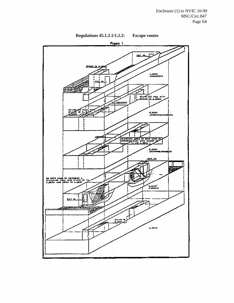
Enclosure (1) to NVIC 10-99MSC/Circ.847
Page 64
Regulations 45.1.2.1/1.2.2: Escape routes

Enclosure (1) to NVIC 10-99MSC/Circ.847
Page 65
65

Enclosure (1) to NVIC 10-99MSC/Circ.847
Page 66
66
Regulation 46.1: Staircases

Enclosure (1) to NVIC 10-99MSC/Circ.847
Page 67
67
Regulation 56: Corner-to-corner situation in a cofferdam
Open Deck
Cargo Tank Ballast Tank
Safe Space
Diagonal plateacross the corner

Enclosure (1) to NVIC 10-99MSC/Circ.847
Page 68
68
Regulation 62.13.4.1: Isolation arrangements in inert gas main
________