NUREG/CR-4652, "Concrete Component Aging and Its Significance ...
I
NUREG/CR4564BNL-NUREG-51971
OPERATING EXPERIENCE AND AGING-SEISMICASSESSMENT OF BATTERY CHARGERS
AND INVERTERS
W.E. Gunther, M. Subudhi, and J.H. Taylor
June 1986
DEPARTMENT OFENGINEERING TECHNOLOGY DIVISION
NUCLEAR ENERGY, BROOKHAVEN NATIONALUPTON, NEW YORK 11973
LABORATORY
�1`11�?�".k .
'.g-. tF1
Prepared for the U.S. Nuclear Regulatory CommissionOffice of Nuclear Regulatory Research
Under Contract No. DE-AC02-76CH00016
M M - �01
NUREG/CR-4564BNL-NUREG-51971
AN, RV
OPERATING EXPERIENCE AND AGING-SEISMICASSESSMENT OF BATTERY CHARGERS
AND INVERTERS
W.E. Gunther, M. Subudhi, and J.H. Taylor
Manuscript Completed: March 1986Revisions Made: April 1986Date Published: June 1986
PLANT SYSTEMS AND EQUIPMENT ANALYSIS GROUPENGINEERING TECHNOLOGY DIVISIONDEPARTMENT OF NUCLEAR ENERGY
BROOKHAVEN NATIONAL LABORATORYUPTON, NEW YORK 11973
Prepared forUNITED STATES NUCLEAR REGULATORY COMMISSION
OFFICE OF NUCLEAR REGULATORY RESEARCHWASHINGTON, D.C. 20555
FIN A-3270
NOTICE
This report was prepared as an accountof work sponsor ed by an agency of the UnitedStates Government Neither the United States Government nor any agency thereof, orany of their employees, makes any warranty, expressed or implied, or assumes anylegal liability or responsibility for any third party's use, or the results of such use, ofany infoRmation, apparatus, product or process disclosed in this report, or representsthat its use by such third party would not infringe privately owned rights
The views expiessed in this report are not necessarily those of the U S NuclearRegulatory Commission
Available fromSupetintendent of Documents
U S Goveinment Pinting OfficePO Box 37082
Washington, DC 20013-7982and
National Technical Infoimation ServiceSpringfield, Virginia 22161
-iII-
ABSTRACT
This report provides an assessment of the aging of battery chargers and in-verters which are vital components of the nuclear power plant electrical safetysystem, and was conducted under the auspices of the XRC Nuclear Aging Research(WPAR) Program. The objectives of this program are to identify concerns relatedto the aging and service wear of equipment operating in nuclear power plants, toassess their possible impact on plant safety, to identify effective inspection,surveillance, and monitoring methods, and to recommend suitable maintenancepractices for mitigating aging-related concerns and diminish the rate of degra-dation due to aging and service wear.
Battery charger and Inverter design and materials of construction are re-viewed to identify age-sensitive components. Operational and accidental stres-sors are determined, and their effect on promoting aging degradation are asses-sed. Variations in plant electrical designs, and system and plant level impactshave been studied. Failure modes, mechanisms, and causes have been reviewedfrom operating experiences and existing data banks. The study has also consi-dered the seismic correlation of age-degraded components within battery chargersand inverters.
The performance indicators that can be monitored to assess component dete-rioration due to aging or other accidental stressors are identified. Conformingwith the NPAR strategy as outlined in the program plan, the study also includesa review of current standards and guides, maintenance programs, and researchactivities pertaining to nuclear power plant safety-related battery chargers andinverters.
CONTENTS
Page
ABSTRACT~oo~eoooooeoooooo~ooesooo............... s**** e **... assess
SUMMAXY, ..................a.................... . ......see................................0..........a.....a............ . . xi. .. .. . xii
1CNWEGMN.4........................... Strategy......................................................... 1-7i
1.0 INTRODUCTION AND INVERTER OPERATING CKAEACTERISTICS........... 1-1
1.1 Backgroundy .......... 1-11.2 Objective............................ .................................... 1-4
1.3 Scope ..S.C S.oiSt.ate C g.............................. 1-51.4 Strategye..........il.c 1mplifer.Batery.Chrger......... 2-7
2.0 BATTERY CHARGER AND INVERTER OPERATING CHARACTERISTICS .......................o................ 2-1
2.1 Battery Charger Types and Principles of Operation ooooo ....... 2-12.1.1 SCR Solid State Chargerter (C)...................... 2-32.1.2 Controlled Ferroresonant Battery Charger ................. 2-52.1.3 Magnetic Amplifi tery Charger.......................... . 2-7
2.2 Inverter Types and Principles of Operation-a .... ...... . ............................ 2-82.2.1 Ferroresonant Type Inverter (CVT).a.,..... .0..... ..........ease............ 2-102.2.2 Pulse Width Modulated (PWK) Inverter* ...... . ............................ 2-122.2.3 Quasi-Square Wave Inverter ... o.oo.o.o.o**.*.o.o........................ 2-132.2.4 Step Wave Inverter................................... 2-142.2.5 Summary of Inverter Types.o.......................... 2-16
2.3 Major Battery Charger and Inverter Sub-components.. ........ 2-172.3.1 Magnetic Components.. .. . .... .. e ................... .*.s. . . 2-182.3.2 Capacitors ...... ...... .0.6.6.......................... 2-202.3.3 Silicon Controlled Rectifiers (SCR) and Silicon Diodes 2-242.3.4 Fuses ..*................................ a. 2-26
2.4 Battery Charger/Inverter Plant Configuration ............... 2-27
3.0 OPERATIONAL STRESSORS AND CORRELATION WITH ACCIDENT SCENARIOS.... 3-1
3.1 System Level Stresses ...............asess...... ............ 3-23.1.1 Loss of ac Power.................. ................... 3-33.1.2 Stresses Incurred During Accident Conditions......... 3-73.1.3 Stresses Due to Electrical Disturbances-............. 3-7
3.2 Component Level Stresses.. .......................... 3-10
3.3 Testing Induced Stresses.........3... 3-12
-vi-
CONTENTS (Cont'd)
3.4 Human Factors ......................... ......... 3-15
3.5 Synergistic Effects.. ................. ............. .... e. 3-17
3.6 Aging - Seismic Correlation ........ ................................. 3-17
3.6.1 Assumptions/Equipment ........ ................ ..... ... 3-18
3.6.2 Dynamic Characteristics ........... ................... 3-20
3.6.3 Aging Characteristic ................................. 3-223.6.4 Age-Degradable Components Vulnerable to Seismic Loads 3-24
3.6.5 Conclusions ....... . . ....... .................... ..... 3-26
4.0 DATA EVALUATION AND ASSESSMENTS ....... ..... ........ * ...... ....... 4-1
4.1 Licensee Event Report (LER) Review ................ 4-1
4.2 In-Plant Reliability Data System (IPRDS) Review*.......... ..... 4-9
4.2.1 Battery Charger IPRDS Data ..... * ..................... 4-10
4.2.2 Inverter IPRDS Data ............ ... .*....a.......... 4-13
4.3 Nuclear Plant Reliability Data System (NPRDS) Review ........ 4-15
4.4 Balance of Data Review ............. o.... ....................... . 4-20
4.4.1 Nuclear Power Experience (NPE) Reports ............... 4-20
4.4.2 Plant Maintenance Records............................ 4-21
4.5 Other Information Sources Including Published Reports ....... 4-24
4.5.1 NSAC/44; Investigations of Failures in I&C PowerSupply Hardware. ..... ........... . ......... * ...... 4-24
4.5.2 NUREG/CR-3808; Aging-Seismic Correlation Study onClass 1E Equipment ....... 0.................... .... 4-24
4.5.3 NUREG/CR-3156; A Survey of the State-of-the-Artin Aging of Electronics With Application to NuclearPower Plant Instrumentation ......................... . 4-24
4.5.4 Vendor Input ........................ ............... 4-25
4.6 Failure Modes/Mechanisms/Causes ........... ..... ..... .. 4-25
5.0 DISCUSSION OF CURRENT METHODS, TECHNOLOGY, AND REQUIREMENTS ...... 5-1
5.1 Equipment Design and Specifications ....................o.... 5-1
5.2 Standards, Guides, and Codes ......... ....... ................ 5-4
5.3 Technical Specifications.- ...... .............. * ............ 5-12
5.4 Manufacturer Recommendations ....... ... ..................... 5-13
5.5 NRC Experience, Expert Knowledge, and On-Going Research ..... 5-14
-vii-
CONTENTS (Cout'd)
Page
6.0 CONCLUSIONS AND RECOMMENDATIONS... ................. ... ......... . 6-1
6.1 CbnClUgions.S.et* ta. *................................ et 6-16.1.1 Design and Fabrication ............................... 6-16.1.2 System Interactions...... ... o........** ......... .....o.. 6-26.1.3 Aging and Service Wear Characteristics .............. 6-26.1.4 Industry and Regulatory Criteria..................... 6-4
6.2 Interim Recommendations... .......................... .... 6-4
6. 3 Future Work.. oos..... ***************.s******. . .......... ......... 6-8
7.0 RFRNE ....... ............... 7-1
-vii-
LIST OF FIGURES
Page
1-1 Simplified Sketch of Nuclear DC System ........................... 1-31-2 Simplified Sketch of Inverter and Vital AC System.. .............. 1-41-3 Research Approach - NPAR Program.......,............ .......... ... 1-51-4 Typical Two Division Electrical Distribution System ............ .. 1-6
2-1 Basic AC to DC Conversion Circuit.*...virc it.................... *... 2-12-2 Three Phase ac to dc Conversion Circuit ...................... 2-22-3 Thyristor Schematic Symbol . .......................... .... . 2-22-4 SCR Solid State Type Charger ................................. *".. 2-32-5 Block Diagram of Typical Three Phase SCR Type Battery Charger .... 2-42-6 Ferroresonant Transformer [7] .................................. 2-62-7 Block Dia gram of Ferroresonant Charger .......................... 2-62-8 Magnetic Amplifier Type Battery Charger ....................... . 2-72-9 Inverter Block Diagram . .......... .... .................... 2-92-10 Ferroresonant Transformer Inverter [3] ................. * 2-112-11 Pulse-Width Modulated Inverter [3]........... ............... 2-122-12 Equivalent SCR Bridge Circuit ........................ 2-132-13 Quasi-Square Wave Inverter [3] .................................. 2-142-14 Step Wave Inverter (6 Steps) [ 3] ................................ 2-152-15 Electrical Schematic of Electrolytic Capacitor (3] ............... 2-202-16 Effect of Temperature on Capacitor Life [3] ...................... 2-222-17 Effect of Voltage on Life For a Typical Capacitor [3] ............ 2-232-18 Life vs Percent Rated Ripple Current & Ambient Temp. [31 ......... 2-232-19 Typical SCR used in Rectifier Applications ................ ....... 2-252-20 Two Division System - One Battery Charger Per Division ........ ... 2-292-21 Two Division System With Two Battery Charger/Inverter
Per Division - No Standby . ........ ........ ..... * 2-302-22 Typical 4 Division System with Spare Battery Charger Concept ..... 2-30
3-1 Battery Charger - Inverter Al i g n m e nt..................... . ........ 3-43-2 Time Line Diagrams of Effects of Offsite Power Outages ........... 3-53-2 [LERs and NPRDS]..(Cotd). .......................... 3-63-3 Component Failures Due to System Electrical Disturbances
(LER & NPRDS Data 1974-1984)[Inverters & Battery Chargers] ....... 3-83-4 Time Line Diagrams of Transient Effects on Equipment
Failure [LERs and NPRDS] ............................ ..3-9
3-5 Component Failures Due to Overheating [LERs & NPRDS Data 1974-1984] 3-113-6 Change in Capacitance Value With Temperature ................. o.. 3-123-7 Battery Charger Test Failure Cause (NPRDS & LER 1976-19 84) ..... 3-143-8 Personnel Errors - Battery Chargers & Inverters . ............ 3-163-9 Skid Mounted Three Phase Battery Charger ......................... 3-183-10 Wall Mounted Single Phase Battery Charger ........................ 3-19
4-1 Battery Charger & Inverter LERs (1976-1984) ...................... 4-44-2 Battery Charger & Inverter LERs by Year ......................... 4-44-3 Capacitor Failures by Plant Age [LERs 1976-1984] ................ 4-54-4 Inverter Failure Effects on Plant Performance [LERs 1976-19841 ... 4-64-5 Inverter Failure Mechanisms [LEES 1976-1984] ..................... 4-74-6 Battery Charger Failure Mechanisms [LERs 1976-1984 . . 4-8
-ix-
LIST OF FIGURES (CONT'D)
Page
4-7 Battery Charger Catastrophic Failure/Age Correlation[IPRDS 1974-19811 ........................................................... 4-10
4-8 Battery Charger Combined Failure/Age Correlation[IPRDS 1974-1981J ............................................... 4-11
4-9 Inverter Failure/Age Correlstion [IPRDS 1974-1981] ............. 0 . 4-134-10 Sample NPRDS Data Input .................. 4-164-11 Inverter Failure Mechanisms [NPRDS 1973-19841.. .............. .... 4-174-12 Battery Charger Failure Mechanisms [NPRDS 1973-1984] ............. 4-174-13 Reactor Protection System (RPS) Reliability Data
fNPRDS Annual Report, 7/74 - 12/821 .............................. 4-194-14 Emergency Core Cooling Systems Reliability Data
[NPRDS Annual Report, 7/74 - 12/82 .............................. 4-204-15 Battery Charger/Inverter Failure History ......................... 4-23
6-1 Performance Indicators for Electrolytic and OilFilled Capacitorso ............... o................................ 6-5
6-2 Performance Indicators for Magnetic Components................... 6-66-3 Performance Indicators for Semiconductor Devices.................. 6-6
-xi-
SUMARY
An aging assessment of battery chargers and inverters was conducted underthe auspices of the NRC Nuclear Plant Aging Research (NPAR) Program. The inten-tions of this program are to resolve issues related to the aging and servicewear of equipment and systems at operating reactor facilities and to assesstheir impact on safety.
Inverters and battery chargers used in nuclear power plants perform signi-ficant functions related to plant safety and availability. The specific impactof a battery charger or Inverter failure varies with plant configuration. Oper-ating experience data have demonstrated that reactor trips, safety injectionsystem actuations, and inoperable emergency core cooling systems have resultedfrom inverter failures; and de bus degradation leading to diesel generator in-operability or loss of control room annunciation and indication have resultedfrom battery and battery charger failures. For the battery charger and inver-ter, the aging and service wear of subcomponents have contributed significantlyto equipment failures.
To identify aging and service wear effects and appropriate inspection/surveillance/monitoring techniques, it was necessary to examine potential fail-ure modes, mechanisms, and causes. This was achieved by reviewing BatteryCharger and Inverter design and materials of construction, by establishing thestressors that are both operational and accident related, and by reviewingexisting failure related data. Aging-seismic correlation was addressed duringthis phase of the program. An interim review of current standards, manufac-turer's recommendations, and condition monitoring techniques was performed toaid in the determination of future work.
The three types of battery charger designs are the Silicon Controlled Rec-tifier (SCR) solid state type, the controlled ferroresonant, and the magneticamplifier (mag amp). Although all three types are used at nuclear facilities,the SCR or thyristor solid state charger is most commonly used, making up nearly752 of the population, and, in fact, is the only charger type that is qualifiedto IEEE-323 and IEEE-650.
Four basic inverter designs are currently in use: the ferroresonant trans-former, the pulse-width modulated, the quasi-square wave, and the step wave.The first two types are used most often, with the last two types making up lessthan 202 of the inverter population.
The charger and inverter subcomponents most susceptible to aging are capa-citors, transformers and inductors, and silicon controlled rectifiers (includingdiodes). High voltage, current, humidity, or temperature will affect all thesecomponents. A large number of charger and inverter failures have resulted fromfuse operation. Some of these failures may be due to thermal fatigue of thefuse. This possibility will be investigated further.
Plant configurations help determine battery charger and inverter reliabil-ity. Those plants that have a standby charger or a second full capacity chargergenerally are the most reliable. For inverters, those plants with transferswitches, which allow a separate bypass ac feed appear to be the most reliable.Those plants with rectifiers providing an alternate dc feed to the inverter,have not been nearly as reliable.
-Xii-
The weak links that may be susceptible to seismic excitation are cabinetmountings to floor or wall, subcomponent mountings, wire and cable connections,relays and circuit breakers, transformers, oil filled capacitors, ahd fuseholders.
Battery charger and inverter failures exhibit the typical 'bathtub' curvewhen plotted against component age. That is, a high number of failures occur inthe first year of operation with a pronounced wear-out effect In the fifth andsixth years of operation.
Over a nine year period, forty two reactor trips have been attributed toinverter failures, thereby demonstrating the safety significance of this compo-nent. Inoperable Emergency Core Cooling Systems (ECCS) and inadvertent safetysystem actuations have also been attributed to inverter failures.
Specific utility source information is presented which demonstrates thatbattery charger and inverter performance can be improved through a comprehensivepreventive maintenance program supported by appropriate personnel training. Inaddition, a review of some of the key subcomponents employed in both batterychargers and inverters reveals that certain performance indicators may be effec-tive in predicting failure due to aging of the equipment, several of which maybe performed while the equipment Is supplying station loads.
Because of the extensive systems interactions related to charger and inver-ter failures, it is recommended that proper procedures be in place to respond tothese potential failures. Additionally, periodic capacity testing should beconducted to ensure that the capability of this equipment to supply the requiredloads is not diminished because of the aging of key components. Capacity test-ing, while performed by many plants for battery chargers, is not regularly con-ducted for inverters.
Future work, in accordance with the NPAR strategy, will consist of testingnaturally aged battery chargers and inverters under normal and accident condi-tions to validate the performance indicators. Additionally, final recommenda-tions will be established for inspection, surveillance, monitoring, and mainte-nance programs.
-xiii-
ACKNOWLEDGEMENT
The authors wish to thank Mr. Jitendra Vora of the U.S. Nuclear RegulatoryCommission for his assistance and guidance. In addition, we appreciate the'con-tribution of various individuals who provided information for this study includ-ing:
* Messrs. Mike Behr, Don Ogden, and Chris Seyer of Power Conversion Pro-ducts, Inc. Crystal Lake, Illinois.
* Ms. Sue Pritzl of Elgar Corp., San Diego, California.
* Messrs. Richard Bucci and Ibraham Hassan of Ebasco Services, Inc., NewYork, New York.
* Mr. Ray Borkowski, Oak Ridge National Laboratory, Oak Ridge, Tennessee.
* Ms. Sharon Brown, EG&G, Idaho, Inc., Idaho Falls, Idaho.
* Mr. William Kosarko, Cyberex, Inc., Mentor, Ohio.
* Mr. David Emery, C&D Power Systems, Plymouth Meeting, Pa.
The response from contacted utilities was very good. Although too numerousto mention individually, the valuable input from maintenance and electricalsupervisors is acknowledged.
We would like to express our gratitude to various members of the Engineer-ing Technology Division of BNL who contributed to this work.
The assistance of Mrs. Ann C. Fort in the typing of this report is alsoappreciated.
1-1
1.0 INTRODUCTION
1.1 Background
Nuclear power plants use battery chargers and inverters to supply power tosafety-related equipment, instrumentation, and controls. A battery charger con-verts alternating current (ac) to direct current (dc) to provide power to de-driven equipment and components as well as to keep the standby batteries fullycharged. Some plants are designed with a standby charger in addition to the re-quired number of units (typically two to four per plant). On the other hand,inverters are used to supply Ac-power to safety related equipment and equipmentimportant to plant operation after converting the dc-power source to an ac out-put. A typical plant design requires at least two such units to distributepower to various control equipment vital to power and safe shutdown operations.Plant systems such as the Reactor Protection System (RPS), Emergency Core Cool-ing System (ECCS), Reactor Core Isolation Cooling (RCIC) System, and the ac/dcdistribution system use these devices to satisfy certain nuclear power stationsafety requirements. Loss of a battery charger or inverter could significantlyimpact plant safety due to any of these systems becoming inoperable.
Both battery chargers and inverters are considered together in this studybecause of their similarities In design, construction, parts and materials. Thesub-components, particularly the electronic elements such as diodes, relays,capacitors, integrated circuits, etc. are the same in both equipment. They alsoserve related safety functions in the plant and experience the same environmentas well as similar operational stresses. In recent years, Improvements in de-sign and construction have been made on chargers and inverters to mitigate someof the earlier problems associated with their older counterparts. Despite thecontinuous effort in improving the product, this equipment can fail because of amalfunction or failure of one or more subcomponents such as capacitors, fuses,and relays. Because of their safety Implications, it is absolutely necessary todetect defects and, if possible, to characterize charger and inverter perfor-mance to assure their availability during all phases of plant operation, includ-ing postulated accident conditions.
Surveys [11 of several failure data sources which are based on the operat-ing experience of control devices in nuclear power plants within the UnitedStates have indicated that battery chargers and inverters significantly contri-bute to the loss of power to essential ac and dc loads. Several studies bygovernment agencies [21 and industry organizations (31 have suggested somemeasures to improve reliability. However, these studies have concentrated pri-marily on the inverter failures rather than battery charger, and used only oneof the failure data bases.
A comprehensive study of battery charger and inverter aging, service wear,and the potential for degradation due to operational as well as accident stres-ses is essential. Development of a cost effective maintenance and surveillanceprogram based on successful monitoring techniques identified by this study canimprove plant safety and performance. In achieving this goal, it will be impor-tant to understand the functions of this equipment during both normal poweroperations and accident events.
1-2
During normal power operation, battery chargers have the dual role of sup-plying dc loads while maintaining the station batteries in a fully chargedstate. In the event of a loss of ac power, which renders the battery chargerinoperable, the batteries must be fully charged in order to have sufficientstored capacity to meet the design requirements for safe shutdown of thereactor. These specific design requirements are identified in the plant FinalSafety Analysis Report (FSAR) and generally specify that the battery be capableof supplying safety-related equipment following a loss of ac power for up toeight hours.
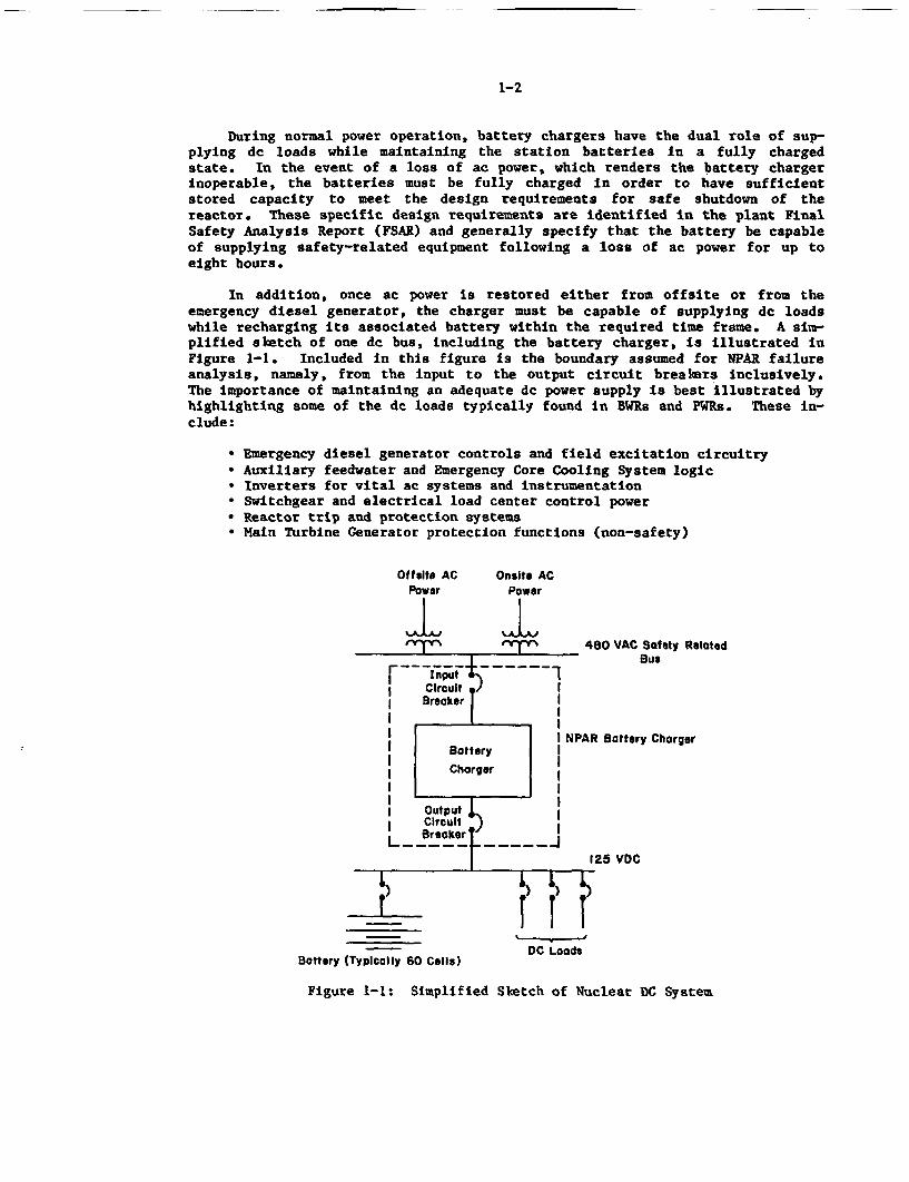
In addition, once ac power is restored either from offaite or from theemergency diesel generator, the charger must be capable of supplying dc loadswhile recharging its associated battery within the required time frame. A sim-plified sketch of one de bus, including the battery charger, is illustrated inFigure 1-1. Included in this figure is the boundary assumed for NPAR failureanalysis, namely, from the input to the output circuit brealers inclusively.The importance of maintaining an adequate dc power supply is best illustrated byhighlighting some of the de loads typically found in BWRs and PM~s. These in-clude:
* Emergency diesel generator controls and field excitation circuitry* Auxiliary feedwater and Emergency Core Cooling System logic• Inverters for vital ac systems and instrumentation* Switchgear and electrical load center control power* Reactor trip and protection systems* Main Turbine Generator protection functions (non-safety)
Wetsit ACPower
IOnsite AC
Power
Irvyyy
Input E 1
I Circuit) II Brooker I
I II II Battery II IICharger II II II Output I
CircuitI Brooker t IL ]
480 VAC Sofety RelatedBus
NPAR Battery Charger
125 VDC. . .T
Bottory (Typically 60 Calls)
C Lo) IdDC Loads
Figure 1-1: Simplified Slktch of Nuclear DC System
1-3
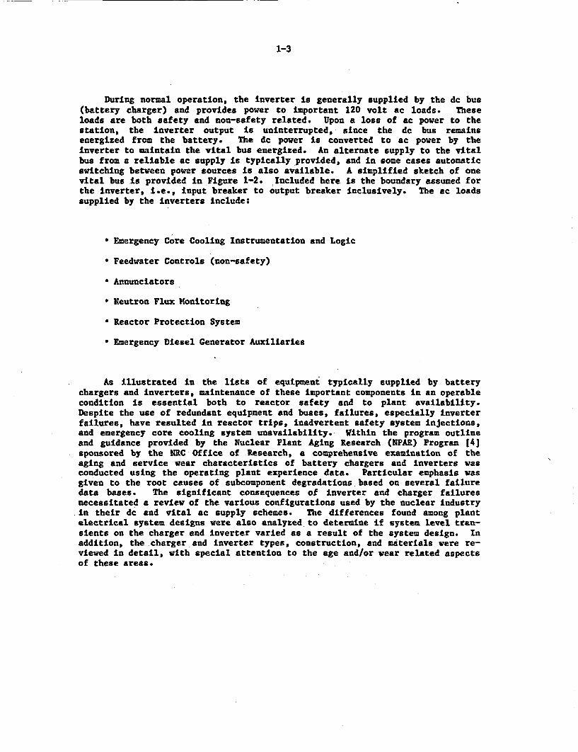
During normal operation, the inverter is generally supplied by the dc bus(battery charger) and provides power to important 120 volt ac loads. Theseloads are both safety and non-safety related. Upon a loss of ac power to thestation, the inverter output is uninterrupted, since the dc bus remainsenergized from the battery. The dc power is converted to ac power by theinverter to maintain the vital bus energized. An alternate supply to the vitalbus from a reliable ac supply is typically provided, and in some cases automaticswitching between power sources is also available. A simplified sketch of onevital bus is provided in Figure 1-2. Included here is the boundary assumed forthe Inverter, i.e., input breaker to output breaker inclusively. The ac loadssupplied by the inverters include:
* Emergency Core Cooling Instrumentation and Logic
* Feedwater Controls (non-safety)
* Annunciators
* Neutron Flux Monitoring
* Reactor Protection System
* Emergency Diesel Generator Auxiliaries
As illustrated in the lists of equipment typically supplied by batterychargers and inverters, maintenance of these important components in an operablecondition is essential both to reactor safety and to plant availability.Despite the use of redundant equipment and buses, failures, especially inverterfailures, have resulted In reactor trips, inadvertent safety system injections,and emergency core cooling system unavailability. Within the program outlineand guidance provided by the Nuclear Plant Aging Research (NPAR) Program 14]sponsored by the NRC Office of Research, a comprehensive examination of theaging and service wear characteristics of battery chargers and inverters wasconducted using the operating plant experience data. Particular emphasis wasgiven to the root causes of subcomponent degradations based on several failuredata bases. The significant consequences of inverter and charger failuresnecessitated a review of the various configurations used by the nuclear industryin their dc and vital ac supply schemes. The differences found among plantelectrical system designs were also analyzed to determine if system level tran-sients on the charger and inverter varied as a result of the system design. Inaddition, the charger and inverter types, construction, and materials were re-viewed in detail, with special attention to the age and/or wear related aspectsof these areas.
1-4
NPAR InverterBoundary
Transformer 480/120VACI INVERTER
l lI Output Circuit I
Alternate I BreakerSupply to IVital Bus I I
Transfer Switch
Vital Bus) ;) A A 20VAC
r T_ TAC Loads
Figure 1-2: Simplified Sketch of Inverter and Vital AC System
1.2 Objective
In accordance with the NRC-NPAR Program Plan, the following are the primarygoals of the study:
1. To identify and characterize aging and service wear effects which, ifunchecked, could cause degradation of structures, components, and sys-tems and thereby impair plant safety.
2. To identify methods of inspection, surveillance and monitoring, or ofevaluating residual life of structures, components, and systems, whichwill assure timely detection of significant aging effects prior to lossof safety function.
3. To evaluate the effectiveness of storage, maintenance, repair, and re-placement practices in mitigating the effects of aging and diminishingthe rate and extent of degradation caused by aging and service wear.
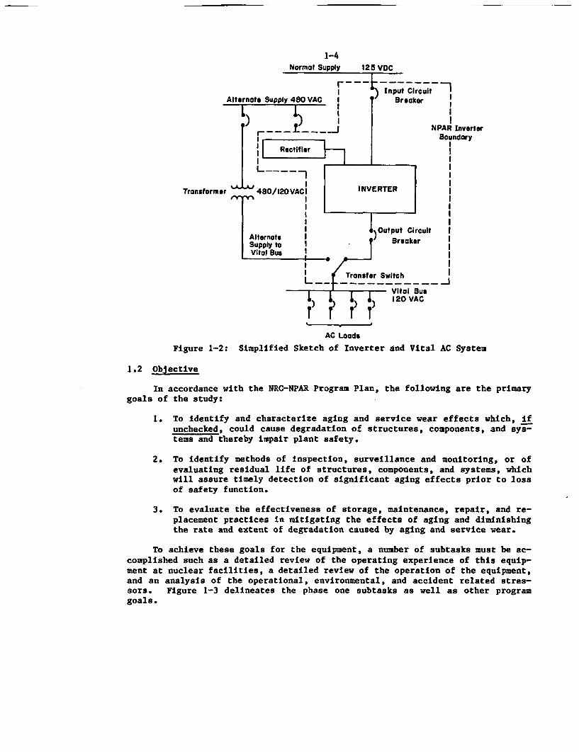
To achieve these goals for the equipment, a number of subtasks must be ac-complished such as a detailed review of the operating experience of this equip-ment at nuclear facilities, a detailed review of the operation of the equipment,and an analysis of the operational, environmental, and accident related stres-sors. Figure 1-3 delineates the phase one subtasks as well as other programgoals.
1-5
melectSystems
andComponents #
forAssessment
Phasel Phase 11
* Operating ExperienceReview and Analysis * Verification of Improved
* Review of Methods I S. and MM**nd Technology for C Tests of NaturallyI S. and MM Aged Components, and
* Screening Type Components Models.Examination and Tests Samples with Simulated
a Interim Recommendations Cegradationfor Engineering Tests * Cost/Benefit Studyin Phase It
zecommen ations to* I, S. and MM* Evaluationof Mothballs
Equipment* Modification of Codes
Standards and Guidesa Utetims Extensions
1 1 S. and MM - Inspection Surveillance and Monitoring Methods
Figure 1-3: Research Approach - NPAR Program
1.3 Scope
In characterizing the aging and service wear effects of battery chargersand inverters, this study considers the predominant designs used by the nuclearindustry, including the size and arrangement of this equipment in operatingstations. It is to be noted that this equipment is typically located in mildenvironments and is not subject to containment level environmental parameters.Because of their importance for safe shutdown of the plant, this equipment isrequired to be environmentally and seismically qualified according to industrystandards. A discussion of the effects of component performance under opera-tional and environmental conditions is provided. Several failure data bases in-cluding Licensee Event Reports (LER), In-Plant Reliability Data Systems (IPRDS),Nuclear Plant Reliability Data Systems (NPRDS), and Nuclear Power Experience(NPE) are reviewed to determine the failure modes, causes and mechanisms experi-enced in recent years by the nuclear industry and to set priorities for the mostsignificant modes of failures. The study also includes a discussion of manu-facturer recommendations for maintaining reliable equipment, as well as a reviewof industry and government standards relating to testing and maintaining of thisequipment. Standards from the Institute of Electrical and Electronics Engineers(IEEE) and the National Electrical Manufacturers Association (NEMA) specificallyaddress battery chargers and inverters.
The four types of inverters and three battery charger types currently usedIn nuclear applications are discussed In detail with the advantages and disad-vantages of each type noted. Equipment size varies with the electrical bus con-figuration used at the plant, with larger sizes typically employed on a two-division configuration vs. a four-division design. Exceptions to this occurwhen individual utilities add non-safety but operationally important loads tothe inverters or chargers which dictate that a larger unit be employed. Thedata received indicated a range of station battery charger sizes from ratings of100 to 600 amps, while station inverter sizes ranged from ratings of 5 to 200
1-6
kilowatts. For inverters, data were also collected for specific application in-verters such as those used with the HPCI, RCIC, and Auxiliary Feedwater systems.These smaller inverters are generally rated less than one kilowatt. Some lowervoltage battery chargers (24 and 48 volts) were also included in the data if asignificant effect was clearly indicated, such as a loss of nuclear instrumenta-tion. Manufactured by the same suppliers of the larger station chargers whichusually operate at 125 volts, these smaller units were found to operate on thesame principles and contain the identical components as the larger units.
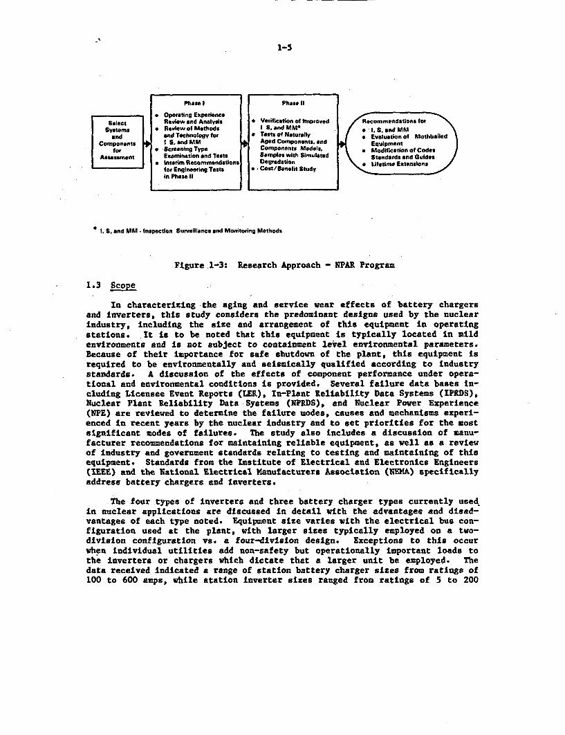
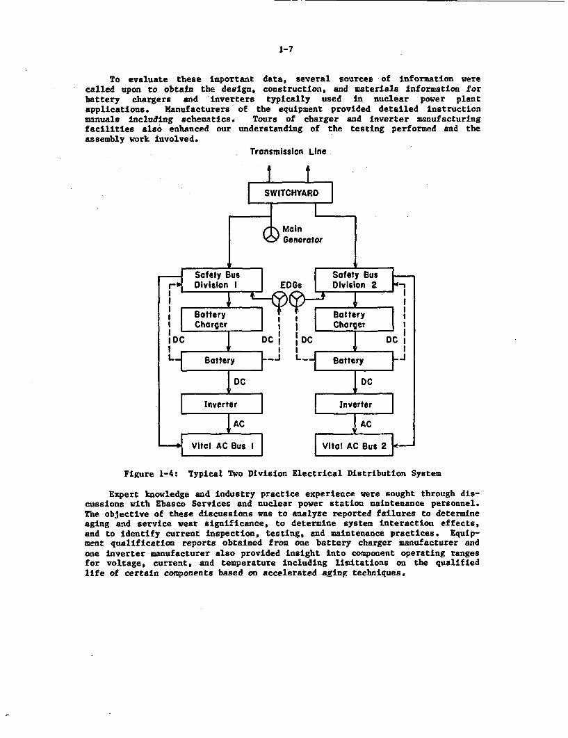
In several reports which discuss uninterruptible power systems in a nuclearpower plant, 'typical' arrangements of battery chargers and inverters are pre-sented. Perhaps the most commonly represented configuration is the two divisionactde electrical distribution system illustrated in Figure 1-4. Although usedin only a small number of plants, generally the older designs, this simple ar-rangement is useful in depicting the relationships of offsite power supplies,emergency diesel generators, battery chargers, batteries, and inverters. Worthyof note are the following:
*The ac supply to the battery charger Is from a safety related source con-nected to the emergency diesel generators.
* The output of the battery charger is connected to the battery which pro-vides the dc input to the inverter, a de input to the emergency dieselgenerators, de control power to safety and non-safety switchgear, and dccontrol power to switchyard devices.
•The inverter is connected in parallel with a supply from the safety re-lated bus to power the 'vital' at bus.
* The two divisions are electrically isolated at the charger/inverter withno cross-connect capability, in order to satisfy the single failure cri-teria.
The study will analyze the various charger/inverter configurations and com-pare them to the failure data reviewed for this report to determine if a corre-lation between design and failure effect exists.
1.4 Strategy
To determine the entire scope of inverter and battery charger failures, itwas first necessary to review and analyze the operating experiences of thisequipment in nuclear power plants. In contrast to previous studies of thisequipment, this was accomplished by an in-depth review of Licensee Event Reports(LERs), the Nuclear Plant Reliability Data System (NPRDS), the In-Plant Reli-ability Data System (IPRDS), Nuclear Power Experience (NPE) data, and directcorrespondence with various nuclear plants. These data were input to a compu-terized data base to allow easy sorting by various categories such as failuremechanism, failure mode, and failure effect.
1-7
To evaluate these important data, several sources of information werecalled upon to obtain the design, construction, and materials information forbattery chargers and Inverters typically used in nuclear power plantapplications. Manufacturers of the equipment provided detailed instructionmanuals including schematics. Tours of charger and inverter manufacturingfacilities also enhanced our understanding of the testing performed and theassembly work involved.
Transmisslon Line
Figure 1-4: Typical Two Division Electrical Distribution System
Expert knowledge and industry practice experience were sought through dis-cussions with Ebasco Services and nuclear power station maintenance personnel.The objective of these discussions was to analyze reported failures to determineaging and service wear significance, to determine system interaction effects,and to identify current inspection, testing, and maintenance practices. Equip-ment qualification reports obtained from one battery charger manufacturer andone inverter manufacturer also provided insight into component operating rangesfor voltage, current, and temperature including limitations on the qualifiedlife of certain components based on accelerated aging techniques.
- - -- - -
1-8
Section 2 of this report provides a general understanding of charger andinverter construction, design, and principles of operation. Contained here arethe technical descriptions of the types of chargers and inverters used in thenuclear industry, including a description of system configurations. Section 3describes the internal and external stressors contributing to equipment failureand how these stressors relate to normal, accident, and seismic events. Section4 describes in detail the data evaluation from the sources used relating thesefailures to the time domain and emphasizing the impact of equipment failure onsafety system performance and plant availability. An interim review of methodsand technology available for inspection, surveillance, and monitoring as definedby industry standards and regulatory guides is presented in Section 5, whileSection 6 summarizes the efforts in this report and describes the direction ofactivity to achieve the results required in phase 2 including a discussion ofthe performance indicators which may be monitored to determine equipment degra-dation prior to failure.
2-1
2.0 BATTERY CHARGER AND INVERTER OPERATING CHARACTERISTICS
This section describes the materials, construction, and operating princi-ples of the battery chargers and inverters used in nuclear power plants. Itprovides a detailed description of the various types of battery chargers and in-verters employed by the nuclear industry as well as some of their key compo-nents. An analysis of these key components and their material characteristicsis presented. Failure of subcomponents under normal/accident conditions and itsimpact on the overall performance of the equipment are discussed.
2.1 Battery Charger Types and Principles of Operation
The basic feature common to all ac to dc converters is that they are con-nected to a source of ac voltage which, through a rectification process, pro-vides a dc power output. A number of circuits are used in this process, rangingfrom the simple half wave single phase rectifier used for low current dc powersupplies to the three phase multipulse converters commonly used in nuclear bat-tery charger applications. The three types of battery charger designs that willbe described are the Silicon Controlled Rectifier (SCR) solid state types, thecontrolled ferroresonant battery charger, and the magnetic amplifier (mag amp)circuit based charger. Although all three types are used at nuclear facilities,the SCR or thyristor solid state type charger is the most widely used charger insafety related nuclear applications making up nearly 75% of the charger popula-tion, and, in fact, it is the only type now qualified to IEEE-323-1974 [5] andIEEE 650-1979 (61. The mag amp and controlled ferroresonant type chargers com-prise the remaining types used and are approximately equal in population. Theadvantages of each type are summarized in Table 2-1.
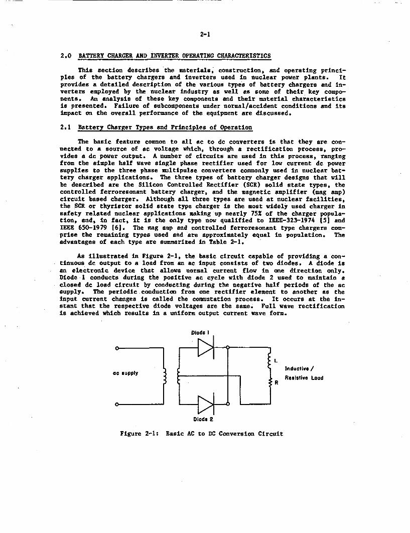
As illustrated in Figure 2-1, the basic circuit capable of providing a con-tinuous do output to a load from an ac input consists of two diodes. A diode isan electronic device that allows normal current flow in one direction only.Diode l conducts during the positive ac cycle with diode 2 used to maintain aclosed dc load circuit by conducting during the negative half periods of the acsupply. The periodic conduction from one rectifier element to another as theinput current changes is called the commutation process. It occurs at the in-stant that the respective diode voltages are the same. Full wave rectificationis achieved which results in a uniform output current wave form.
Diode I
Ll sl Inductive /
Ro supply o23 l $ RResistive Load
Diode 2
Figure 2-1: Basic AC to DC Conversion Circuit
2-2
Inductive /_/ Resistive Load
R
Figure 2-2: Three Phase ac to dc Conversion Circuit
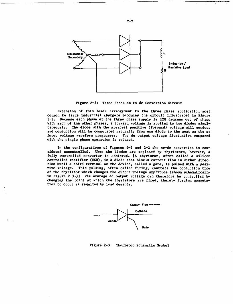
Extension of this basic arrangement to the three phase application mostcommon to large industrial chargers produces the circuit illustrated in Figure2-2. Because each phase of the three phase supply is 120 degrees out of phasewith each of the other phases, a forward voltage is applied to two diodes simul-taneously. The diode with the greatest positive (forward) voltage will conductand conduction will be commutated naturally from one diode to the next as the acinput voltage waveform progresses. The dc output voltage fluctuation comparedwith the single phase operation is reduced.
In the configurations of Figures 2-1 and 2-2 the ac-dc conversion is con-sidered uncontrolled. When the diodes are replaced by thyristors, however, afully controlled converter is achieved. [A thyristor, often called a siliconcontrolled rectifier (SCR), is a diode that blocks current flow in either direc-tion until a third terminal on the device, called a gate, is pulsed with a posi-tive voltage. This pulsing, often called firing, controls the conduction timeof the thyristor which changes the output voltage amplitude (shown schematicallyin Figure 2-3.)] The average dc output voltage can therefore be controlled bychanging the point at which the thyristors are fired, thereby forcing commuta-tion to occur as required by load demands.
Current Flow----
Cathode
Anode
Gate
Figure 2-3: Thyristor Schematic Symbol
2-3
A circuit with two diodes and two SCRs is used most often to provide therectification process. The more complex SCR fired battery chargers like theones used in nuclear power plants also use a 'freewheeling diode". This diodeprovides a current path when the terminal voltage instantaneously tends to gonegative as in the case when no thyristors are conducting. A bypass istherefore provided for inductive load currents if the supply was disconnected.At the same time, the output wave shape is improved as a result of filteringaccomplished by the diode.
2.1.1 SCR Solid State Charger
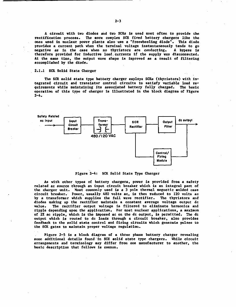
The SCR solid state type battery charger employs SCRs (thyristors) with in-tegrated circuit and transistor control circuits to satisfy variable load re-quirements while maintaining its associated battery fully charged. The basicoperation of this type of charger is illustrated in the block diagram of Figure2-4.
Safety Relatedat Input Input ne- SCR Outpu de cutpyt
Brooker e rRt bz-
480 /1 20 VAC
ControllFiring
Module
Figure 2-4: SCR Solid State Type Charger
As with other types of battery chargers, power is provided from a safetyrelated ac source through an input circuit breaker which is an integral part ofthe charger unit. Most commonly used is a 3 pole thermal magnetic molded casecircuit breaker. Power, usually 480 volts ac, is then reduced to 120 volts acby a transformer which supplies the full wave rectifier. The thyristors anddiodes making up the rectifier maintain a constant average voltage output devalue. The rectifier output voltage is filtered to eliminate harmonics andripple depending upon the application. For most nuclear applications, a maximumof 2% ac ripple, which is the imposed ac on the dc output, is permitted. The dcoutput which is routed to dc loads through a circuit breaker, also providesfeedback to the solid state control and firing circuits which generate pulses tothe SCR gates to maintain proper voltage regulation.
Figure 2-5 is a block diagram of a three phase battery charger revealingsome additional details found -in SCR solid state type chargers. While circuitarrangements and terminology may differ from one manufacturer to another, thebasic description that follows is common.
2-4
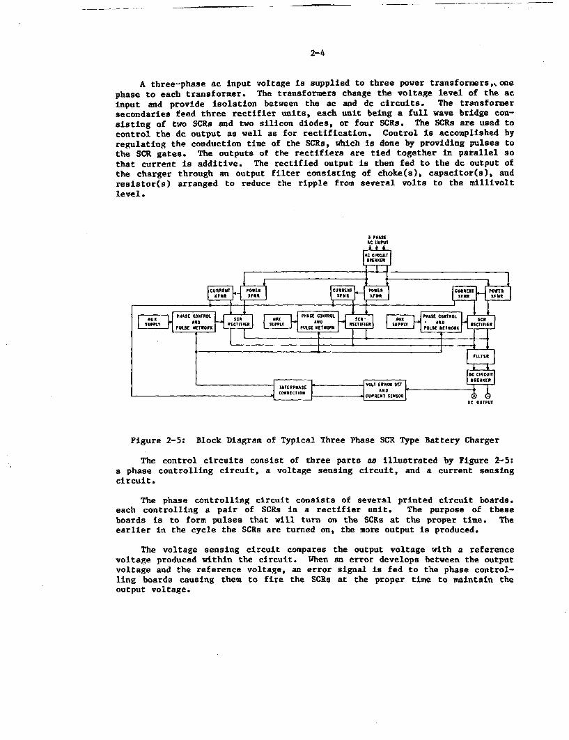
A three-phase ac input voltage is supplied to three power transformers,k onephase to each transformer. The transformers change the voltage level of the acinput and provide isolation between the ac and dc circuits. The transformersecondaries feed three rectifier units, each unit being a full wave bridge con-sisting of two SCRs and two silicon diodes, or four SCRs. The SCRs are used tocontrol the dc output as well as for rectification. Control is accomplished byregulating the conduction time of the SCRe, which is done by providing pulses tothe SCR gates. The outputs of the rectifiers are tied together in parallel sothat current is additive. The rectified output is then fed to the dc output ofthe charger through an output filter consisting of choke(s), capacitor(s), andresistor(s) arranged to reduce the ripple from several volts to the millivoltlevel.
Figure 2-5: Block Diagram of Typical Three Phase SCR Type Battery Charger
The control circuits consist of three parts as illustrated by Figure 2-5:a phase controlling circuit, a voltage sensing circuit, and a current sensingcircuit.
The phase controlling circuit consists of several printed circuit boards.each controlling a pair of SCRs in a rectifier unit. The purpose of theseboards is to form pulses that will turn on the SCRe at the proper time. Theearlier in the cycle the SCRs are turned on, the more output is produced.
The voltage sensing circuit compares the output voltage with a referencevoltage produced within the circuit. When an error develops between the outputvoltage and the reference voltage, an error signal is fed to the phase control-ling boards causing them to fire the SCRs at the proper time to maintain theoutput voltage.
2-5
The current sensing circuit receives a signal from the current transfor-mers. When the output current increases beyond the current limit setting, thesignal from the current sensing circuit overrides the voltage sensing circuitand feeds a signal to the phase control boards which fires the SCRs at the timenecessary to limit the output current to the set level.
Another board that is part of the control circuits ties the signal from thevoltage sensing and phase controlling circuit boards to the signal from the cur-rent transformers. This ensures that the outputs from each of the rectifierunits are at equal levels.
Power is provided to the control circuits by three auxiliary transformers,each with fused secondaries. The primaries of these transformers are connectedto auxiliary windings on the power transformers. The secondary voltages of theauxiliary voltage transformers are in phase with the power transformer voltagesthat supply the rectifier units. These voltages supply the phase control boardswhich in turn control voltage and frequency of the rectifier units.
An ac circuit breaker on the input to the charger protects the charger fromoverloads and short circuits and serves as the disconnect means when maintenanceis being performed on the charger. AC input capacitors are frequently installedto dampen any voltage distortions created by the firing of the SCRs that couldfeedback to the ac source. Fuses on the rectifier units also protect the recti-fier against overload currents. A surge suppressor, consisting of a capacitorand resistor in series, may be connected across the rectifier unit to preventhigh voltage spikes from appearing across the rectifier unit. Surge suppressionmay also be provided by selenium rectifiers or metal oxide varistors designed toreduce voltage transients to a lever that will not damage the power diodes orthyristors (SCRs). A dc circuit breaker on the output of the charger protectsagainst external faults and allows the battery to be connected to the chargerwithout causing arcing due to the capacitors charging or discharging. Contactsare typically supplied on the ac and/or dc circuit breakers to provide localand/or remote alarm capability.
2.1.2 Controlled Ferroresonant Battery Charger
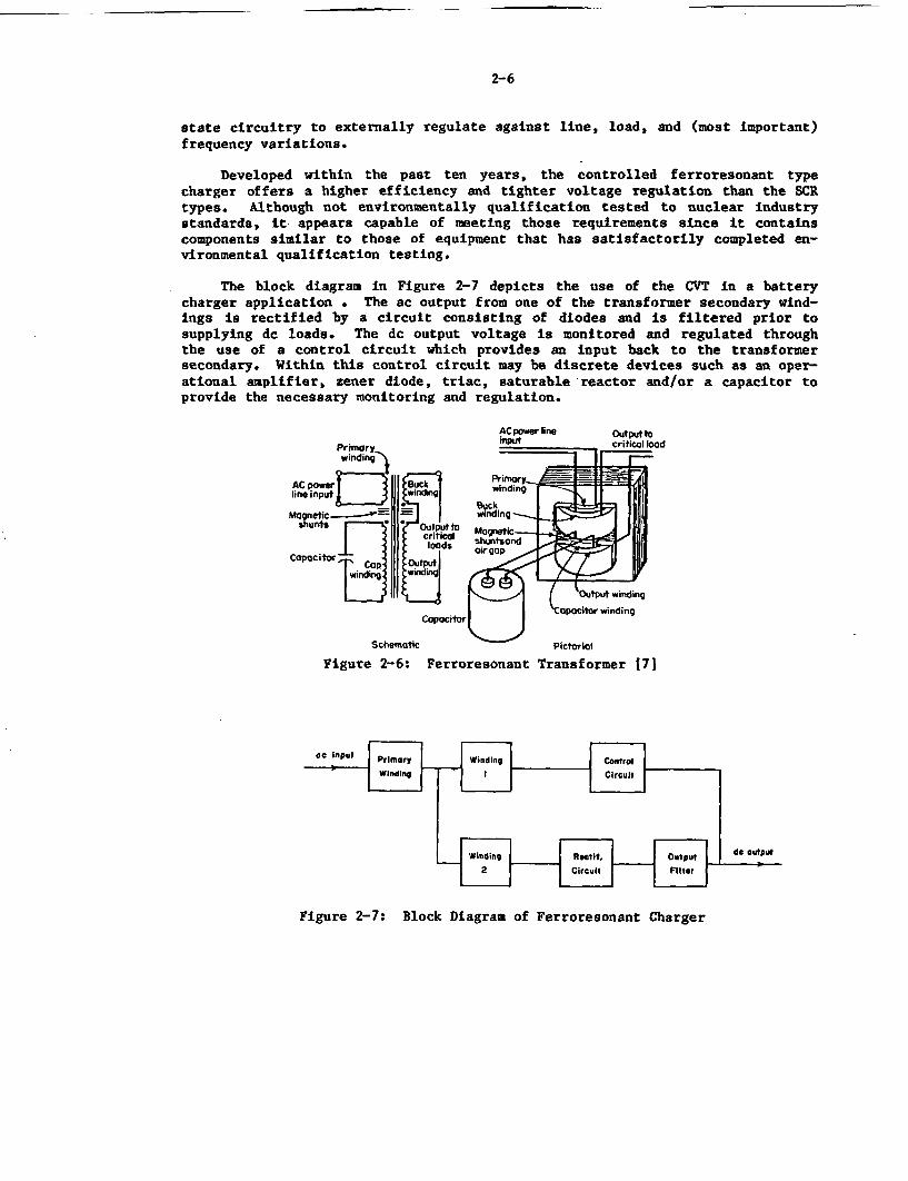
The conventional Ferroresonant Constant Voltage Transformer sometimesreferred to as a CVT, is the heart of the controlled ferroresonant batterycharger and has been used extensively in the past on de power supplies. In thatapplication, its function was to correct for line voltage variations and trans-form an input voltage to the level required by the rectifier and dc circuit. Ata constant frequency, any increase in voltage results in increased excitingcurrent for the saturable transformer. As illustrated by Figure 2-6, the outputwinding is connected in series opposition with a buck winding to reduce thechange in output voltage in response to input voltage changes.
In modern battery chargers the conventional ferroresonant transformer ismodified to obtain the desired output control necessary. Although the conven-tional design provides satisfactory voltage regulation, high efficiency, andtransient suppression capability, this modification was necessary to improve theinput frequency sensitivity characteristics of the conventional ferroresonantcircuit to meet the design performance requirements for a highly regulated bat-tery charger. This modification makes use of the control capabilities of solid
- -
2-6
state circuitry to externally regulate against line, load, and (most important)frequency variations.
Developed within the past ten years, the controlled ferroresonant typecharger offers a higher efficiency and tighter voltage regulation than the SCRtypes. Although not environmentally qualification tested to nuclear industrystandards, it appears capable of meeting those requirements since it containscomponents similar to those of equipment that has satisfactorily completed en-vironmental qualification testing.
The block diagram in Figure 2-7 depicts the use of the CVT in a batterycharger application . The ac output from one of the transformer secondary wind-ings is rectified by a circuit consisting of diodes and is filtered prior tosupplying dc loads. The dc output voltage is monitored and regulated throughthe use of a control circuit which provides an input back to the transformersecondary. Within this control circuit may be discrete devices such as an oper-ational amplifier, zener diode, triac, saturable reactor and/or a capacitor toprovide the necessary monitoring and regulation.
Schematic Pictorial
Figure 2-6: Ferroresonant Transformer [7]
Figure 2-7: Block Diagram of Ferroresonant Charger
2-7
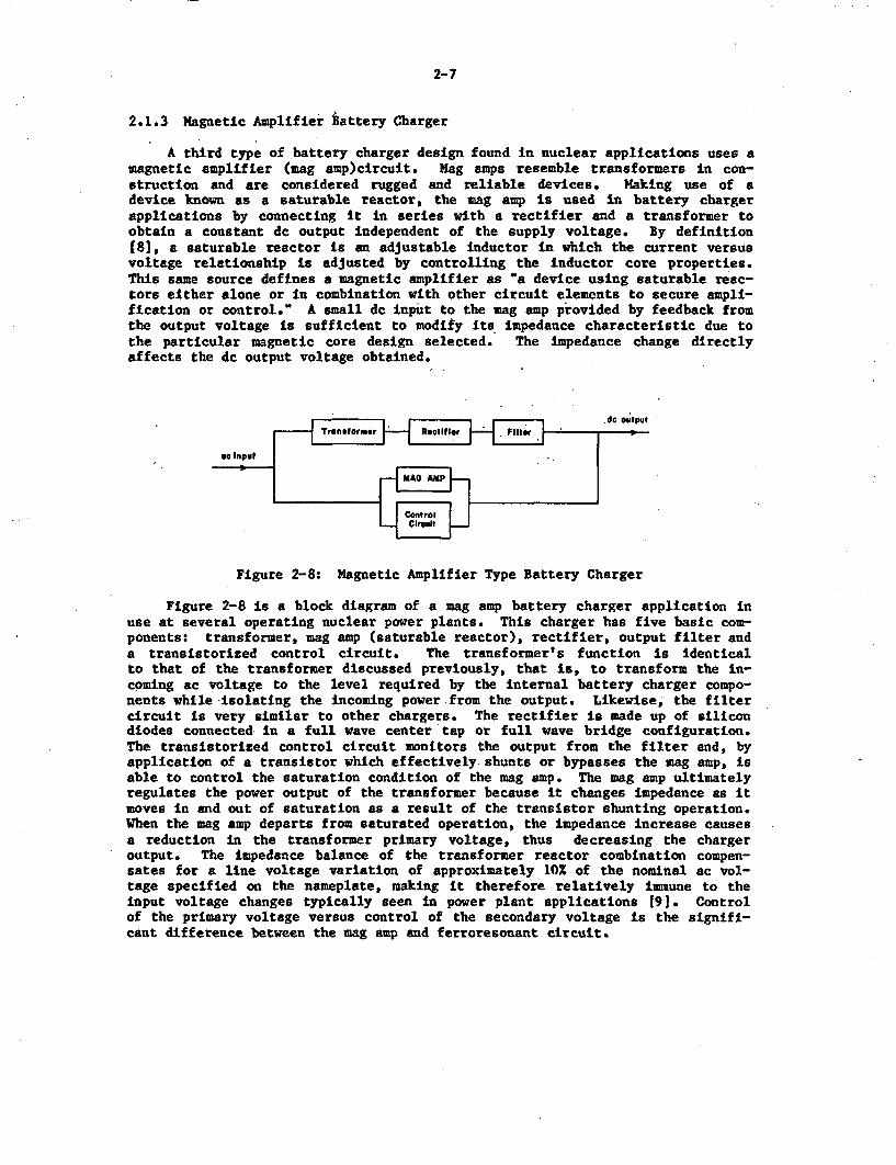
2.1.3 Magnetic Amplifier Battery Charger
A third type of battery charger design found in nuclear applications uses amagnetic amplifier (mag amp)circuit. Hag amps resemble transformers in con-struction and are considered rugged and reliable devices. Making use of adevice known as a saturable reactor, the inag amp is used in battery chargerapplications by connecting it in series with a rectifier and a transformer toobtain a constant dc output independent of the supply voltage. By definition(81, a saturable reactor is an adjustable inductor in which the current versusvoltage relationship is adjusted by controlling the inductor core properties.This same source defines a magnetic amplifier as 'a device using saturable reac-tors either alone or in combination with other circuit elements to secure ampli-fication or control." A small dc input to the mag amp provided by feedback fromthe output voltage is sufficient to modify its impedance characteristic due tothe particular magnetic core design selected. The impedance change directlyaffects the dc output voltage obtained.
eIC Input,
a* In '
_ .A-.
Figure 2-8: Magnetic Amplifier Type Battery Charger
Figure 2-8 is a block diagram of a nag amp battery charger application inuse at several operating nuclear power plants. This charger has five basic com-ponents: transformer, mag amp (saturable reactor), rectifier, output filter anda transistorized control circuit. The transformer's function is identicalto that of the transformer discussed previously, that is, to transform the in-coming ac voltage to the level required by the internal battery charger compo-nents while isolating the incoming power from the output. Likewise, the filtercircuit is very similar to other chargers. The rectifier is made up of silicondiodes connected in a full wave center tap or full wave bridge configuration.The transistorized control circuit monitors the output from the filter and, byapplication of a transistor which effectively shunts or bypasses the mag amp, isable to control the saturation condition of the mag amp. The mag amp ultimatelyregulates the power output of the transformer because it changes impedance as itmoves in and out of saturation as a result of the transistor shunting operation.When the wag amp departs from saturated operation, the impedance increase causesa reduction in the transformer primary voltage, thus decreasing the chargeroutput. The impedance balance of the transformer reactor combination compen-sates for a line voltage variation of approximately 10% of the nominal ac vol-tage specified on the nameplate, making it therefore relatively immune to theinput voltage changes typically seen in power plant applications 19J. Controlof the primary voltage versus control of the secondary voltage is the signifi-cant difference between the mag amp and ferroresonant circuit.
-
2-8
In summary, magnetic amplifiers make use of the property of saturable rqac-tors to control large amounts of power by means of small currents. They providesensitive amplification by means of feedback paths, which introduce a small partof the ac load current after rectification into a control winding of the satur-able reactor. Combined with semiconductor rectifiers, the mag amp charger is arugged device frequently employed in commercial applications and in use at someolder nuclear stations.
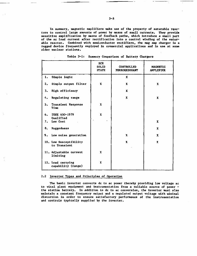
Table 2-1: Summary Comparison of Battery Chargers
SCRSOLID CONTROLLED MAGNETICSTATE FERRORESONANT AMPLIFIER
1. Simple logic X
2. Simple output filter X % X
3. High efficiency X
4. Regulating range X x
5. Transient Response XTime
6. IEEE 650-1979 XQualified
7. Low Cost X
8. Ruggedness X
9. Low noise generation X X
10. Low Susceptibility X xto Transient
11. Adjustable current Xlimiting
12. Load carrying Xcapability (range)
2.2 Inverter Types and Principles of Operation
The basic inverter converts dc to ac power thereby providing low voltage acto vital plant equipment and instrumentation from a reliable source of power -the station battery. In addition to dc to ac conversion, the inverter must alsomaintain a constant frequency output and a regulated output voltage with minimaldistortion in order to ensure satisfactory performance of the instrumentationand controls typically supplied by the inverter.
2-9
The simplest inverters include switching devices which have the ability tointerrupt current flow. Because silicon controlled rectifiers have a high powerrating and can provide very fast and reliable switching action, they are util-ized as the switching device in nuclear power plant inverters.
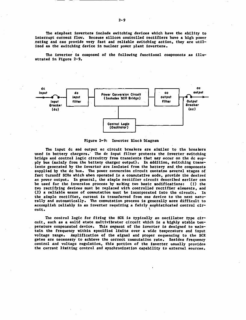
The Inverter is composed of the following functional components as illu-strated in Figure 2-9.
de
Ipth inu dcadotu accrutbekr ar si cla touhe traur
ede by te dc bPower Conversion Circuit cotan s oftu> * _ Input _(Includes 'SCR Bridge) otu
Incutt a tOter tterBro the ib aki( er
(dc) (cc )
I(Oscillactor)I
Figure 2-9: Inverter Block Dlagram
The input dm and output at circuit breakers are similar to the breakersused in battery chargers. The is input filter protects the Inverter swntchingbridge and control logic circuitry from trcssients that may occur on the dl sup-ply bus (mainly from the battery charger output). In addition, switching trans-ients generated by the inverter areI solated from the battery and the componentssupplied by the de bus. The power conversion circuit contains several stages offast turnoff SCRs which when operated in i commutative mode, provide the desiredac power output. In general, the simple rectifier circuit described earlier canbe used for the Inversion process by making two basite modifications: (1) thetwo rectifying devices must be replaced with controlled rectifier elements, and(2) a reliable means of commutation must be incorporated Into the circuit. Inthe simple rectifier, current of transferred from one device to the next natu-gally and automatically. The commutation process is generally Bore difficult toaccomplish reliably in an Inverter requiring a fairly sophisticated control cir-cuit.-K
The control logic for firing the SCR Is typically an oscillator type cir-cuit, such as a solid state multivibrator circuit which Is a highly stable tem-perature compensated device. This segment of the Inverter is designed to main-tain the frequency within specified limits over a wide temperature and inputvoltage range. Amplification of the signal and proper sequencing to the SCRgates are necessary to achieve the correct 'commutation rate. Besides frequencycontrol and voltage regulation, this portion of the inverter usually providesthe current limiting control and synchronization capability to external sources.
2-10
The ac output filter eliminates unwanted harmonies generated so as to pro-vide a sinusoidal waveform output with a minimum of distortion. This filteringcan be achieved by several methods, as described later. The size of the ac fil-ter is dictated not only by the amount of unwanted harmonies, but also by thefrequency of these harmonics, with low harmonic frequencies requiring largerfilters. Consequently, design of the power conversion circuit to reduce oreliminate lower order frequencies results in smaller ac filters.
In many vital bus inverter applications, the inverter is designed to oper-ate from a rectified ac source or a dc supply. In normal operation, power issupplied by the ac power source to operate the inverter. A diode in the feedfrom the dc bus is prevented from conducting by the higher voltage of the acpower supply. When the ac source is unavailable or its voltage is lower thanthe blocking voltage of the diode, the dc bus instantly supplies power to theinverter until the ac line returns to service.
While inverters are -custom-made' for class IE applications using compre-hensive specifications, four basic inverter designs are currently in use: theferroresonant transformer,the pulse-width modulated, the quasi square wave, andthe step wave inverters.
The Ferroresonant or Constant Voltage Transformer (CVT) and Pulse WidthModulated (PWM) designs are most often found in nuclear applications with theferroresonant type existing in older plants and the PWM now being employed inmany new installations. The quasi square wave and the step wave inverters makeup less than 20% of the total population but are discussed in order to provide acomplete picture of nuclear inverter applications.
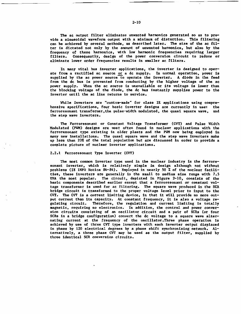
2.2.1 Ferroresonant Type Inverter (CVT)
The most common inverter type used in the nuclear industry is the ferrore-sonant inverter, which is relatively simple in design although not withoutproblems (IE INFO Notice 84-84). Employed in nearly 50 % of the nuclear facili-ties, these inverters are generally in the small to medium size range with 7.5KVA the most popular. The circuit, depicted in Figure 2-10, consists of thebasic components described earlier except that a ferroresonant or constant vol-tage transformer is used for ac filtering. The square wave produced in the SCRbridge-circuit is transformed to the proper voltage level prior to input to theCVT. The CVT is a current limiting device, in that it will provide no more out-put current than its capacity. At constant frequency, it is also a voltage re-gulating circuit. Therefore, the regulation and current limiting is totallymagnetic, requiring no electronics. In addition, the control and power conver-sion circuits consisting of an oscillator circuit and a pair of SCRs (or fourSCRs in a bridge configuration) convert the dc voltage to a square wave alter-nating current at the frequency of the oscillator.Three phase operation isachieved by use of three CVT type inverters with each inverter output displacedin phase by 120 electrical degrees by a phase shift synchronizing network. Al-ternatively, a three phase CVT may be used as the output filter, supplied bythree identical SCR conversion circuits.
2-11
DC I I '* 'l lINPUT
FERRO-RESONANTTRANSFORMIER
Figure 2-10: Ferroresonant Transformer Inverter [3J
Although generally used on smaller inverters, including the inverters usedfor the HPCI and RCIC systems (<lVA), this type of inverter is frequentlyarranged for parallel operation -with one inverter being a master and the otherbeing slaved to it. For example, a 7.5 KVA rated ferroresonant inverter mayactually consist of one 5.0 KVA and one 2.5 KVA inverter arranged in thismaster-slave mode. At least one manufacturer modifies the single phase Ferro-resonant transformer circuit by using a wScott T" transformer connection toobtain three phase performance. This classic connection is used to obtain threephase output from a two phase input. In a Scott connected inverter system, twoSCR bridge assemblies are connected to two single phase ferroresonant transfor-mers. The phase relationship between the two transformers (typically set at 90degrees) determines the inverter output. Feedback to either SCR bridge circuitalters the phase relationship to maintain balanced transformer loading duringunbalanced load operation 1101.
As mentioned earlier, this type of inverter has the advantage of being sim-ple in both the logic and power conversion states. Additionally, it has in-herent current limiting and voltage regulation because of the use of the CVT.Its main disadvantage is, however, that it is unable to operate for extendeddurations under light load conditions because of overheating due to over-excita-tion of the transformer. A second disadvantage is its slow transient responseto load changes because of the dependence of its operation on magnetic action.Other disadvantages include the following:
1. The output voltage cannot be field adjusted.
2. Total harmonic output waveform distortion is high (>5%).
3. Voltage regulation is limited to about ± 22.
4. Efficiency decreases sharply as the load decreases (overheating con-cern).
5. It is incompatible with specialized loads such as large motors andphase controlled power supplies because of the nonlinear circuit of theCVT.
2-12
2.2.2 Pulse Width Modulated (PWM) Inverter
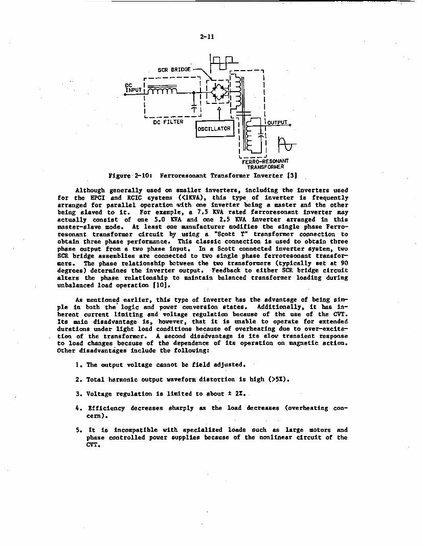
The Pulse Width Modulated (PWM) Inverter, the most advanced of the fourinverter designs to be discussed, is used at many of the newer nuclear plants.As illustrated in Figure 2-11, this design is more complex than the ferro-resonant inverter, containing sophisticated timing and logic circuits to obtainvoltage regulation. The PWM inverter uses a power conversion circuit which gen-erates square waves at much higher frequencies than the desired output fre-quency, usually 600 or 1200 Hz. Operation at these higher frequencies restrictsthe harmonics generated to multiples of these high frequencies, thereby allowingthe filter size to be reduced and improving the transient performance.
SCR BRIDGES
Figure 2-11: Pulse-Width Modulated Inverter 131
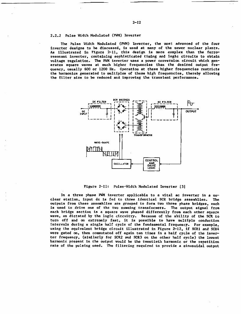
In a three phase PWM inverter applicable to a vital ac inverter in a nu-clear station, input dc is fed to three identical SCR bridge assemblies. Theoutputs from these assemblies are grouped to form two three phase bridges, eachis used to drive one of the two summing transformers. The output signal fromeach bridge section is a square wave phased differently from each other squarewave, as dictated by the logic circuitry. Because of the ability of the SCR toturn off and on extremely fast, it is possible to have multiple conductionintervals during a single half cycle of the fundamental frequency. For example,using the equivalent bridge circuit illustrated in Figure 2-12, if SCRI and SCR4were gated on, then commutated off again ten times in a half cycle of the inver-ter frequency, (similarly for SCR2 and SCR3 on the other half cycle) the lowestharmonic present in the output would be the twentieth harmonic or the repetitionrate of the pulsing used. The filtering required to provide a sinusoidal output
2-13
with acceptable harmonic content is considerably reduced as compared to thatrequired for a square wave. The PWM inverter output voltage is regulated byvarying the width of the pulses supplied by -each bridge section. Inverteroutput frequency is held constant by an oscillator operating at 60 Hz.
SCR I 8CR 3
Input LaVoltage
SCR 2 SCR 4
Figure 2-12: Equivalent SCR Bridge Circuit
Increasing the pulse repetition rate permits further reduction of the fil-tering required. However, there is a definite practical limit to the repetitionrate because of the fixed turn-off time of the SCRs used in the circuit. Theshortest nonconducting time must be greater than the specified turn-off intervalfor the SCR. In addition, the losses due to commutation are proportional to thenumber of commutations per second. As a result, the efficiency of the inverteris reduced as the repetition rate Is increased [l).
In summary, this type of inverter has the following advantages: (1) smal-ler output filters, (2) fast transient response, (3) large load unbalances, and(4) suitability for large (> 10 KVA) designs due to the filter design advantage.Its major disadvantage is the complexity of the logic circuitry required to pro-vide the critical timing for the SCR switching and commutation process.
2.2.3 Quasi-Square Wave Inverter
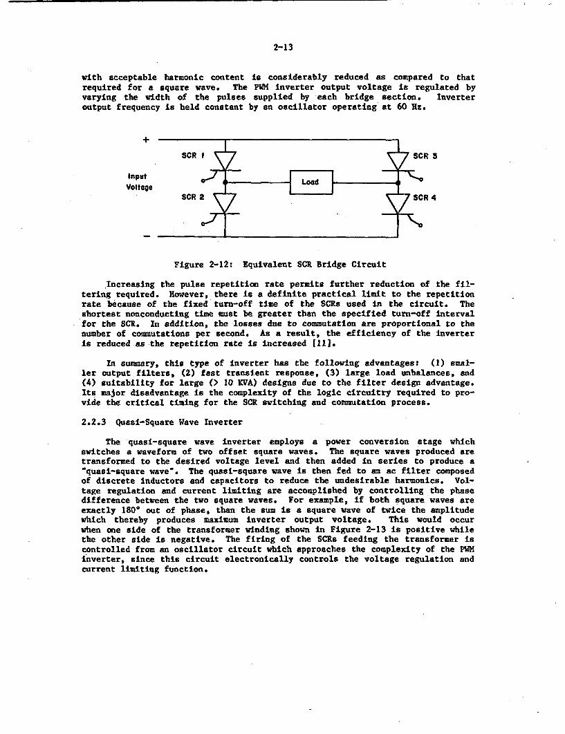
The quasi-square wave inverter employs a power conversion stage whichswitches a waveform of two offset square waves. The square waves produced aretransformed to the desired voltage level and then added in series to produce a.quasi-square wave". The quasi-square wave is then fed to an ac filter composedof discrete inductors and capacitors to reduce the undesirable harmonics. Vol-tage regulation and current limiting are accomplished by controlling the phasedifference between the two square waves. For example, if both square waves areexactly 180° out of phase, than the sum is a square wave of twice the amplitudewhich thereby produces maximum Inverter output voltage. This would occurwhen one side of the transformer winding shown in Figure 2-13 is positive whilethe other side is negative. The firing of the SCRs feeding the transformer iscontrolled from an oscillator circuit which approaches the complexity of the PWMinverter, since this circuit electronically controls the voltage regulation andcurrent limiting function.
2-14
r BRIDG 5C - AC FILTER
INPUTPUT
L- - - - - -- _TRANSFORMERDC FILTER
CURRENT VOLTAGE lLIMIT AMPLIFIER L__AMPLIFIERA
OSCILLATOR
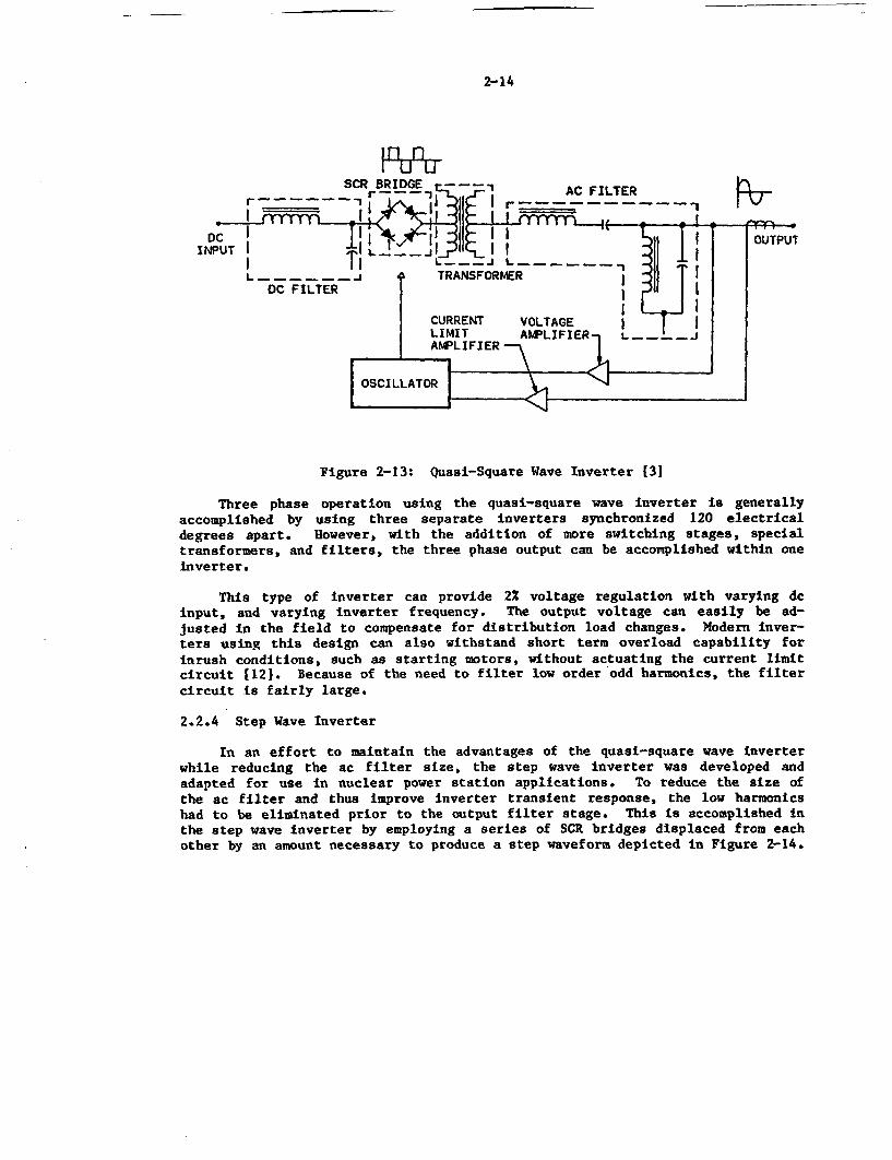
Figure 2-13: Quasi-Square Wave Inverter 131
Three phase operation using the quasi-square wave inverter is generallyaccomplished by using three separate inverters synchronized 120 electricaldegrees apart. However, with the addition of more switching stages, specialtransformers, and filters, the three phase output can be accomplished within oneinverter.
This type of inverter can provide 2% voltage regulation with varying dcinput, and varying inverter frequency. The output voltage can easily be ad-justed in the field to compensate for distribution load changes. Modern inver-ters using this design can also withstand short term overload capability forinrush conditions, such as starting motors, without actuating the current limitcircuit [12). Because of the need to filter low order odd harmonics, the filtercircuit is fairly large.
2.2.4 Step Wave Inverter
In an effort to maintain the advantages of the quasi-square wave inverterwhile reducing the ac filter size, the step wave Inverter was developed andadapted for use in nuclear power station applications. To reduce the size ofthe ac filter and thus improve inverter transient response, the low harmonicshad to be eliminated prior to the output filter stage. This is accomplished inthe step wave inverter by employing a series of SCR bridges displaced from eachother by an amount necessary to produce a step waveform depicted in Figure 2-14.
2-15
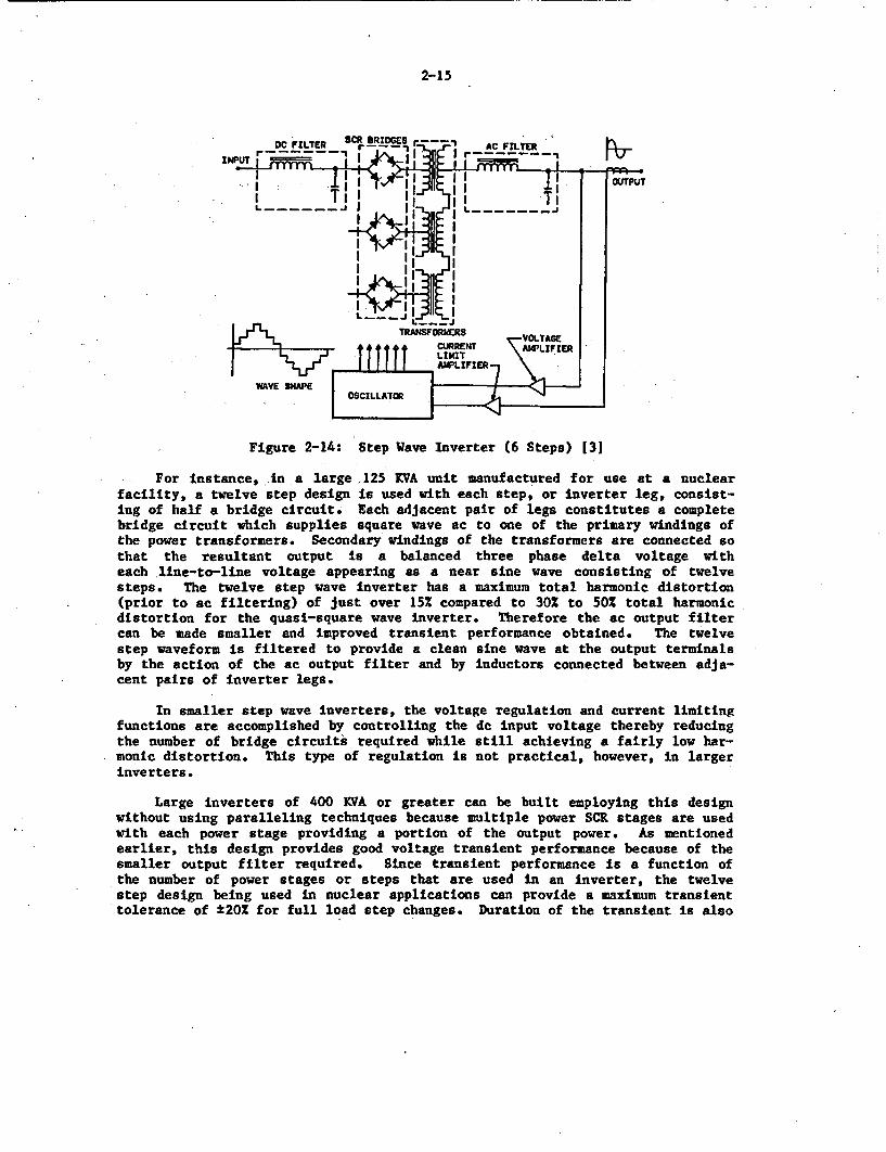
Figure 2-14: Step Wave Inverter (6 Steps) (31
For instance, in a large 125 KVA unit manufactured for use at a nuclearfacility, a twelve step design is used with each step, or inverter leg, consist-ing of half a bridge circuit. Each adjacent pair of legs constitutes a completebridge circuit which supplies square wave ac to one of the primary windings ofthe power transformers. Secondary windings of the transformers are connected sothat the resultant output is a balanced three phase delta voltage witheach line-to-line voltage appearing as a near sine wave consisting of twelvesteps. The twelve step wave inverter has a maximum total harmonic distortion(prior to ac filtering) of just over 15% compared to 30% to 50% total harmonicdistortion for the quasi-square wave inverter. Therefore the ac output filtercan be made smaller and improved transient performance obtained. The twelvestep waveform is filtered to provide a clean sine wave at the output terminalsby the action of the ac output filter and by inductors connected between adja-cent pairs of inverter legs.
In smaller step wave inverters, the voltage regulation and current limitingfunctions are accomplished by controlling the dc input voltage thereby reducingthe number of bridge circuits required while still achieving a fairly low har-monic distortion. This type of regulation is not practical, however, in largerinverters.
Large inverters of 400 KVA or greater can be built employing this designwithout using paralleling techniques because multiple power SCR stages are usedwith each power stage providing a portion of the output power. As mentionedearlier, this design provides good voltage transient performance because of thesmaller output filter required. Since transient performance is a function ofthe number of power stages or steps that are used in an inverter, the twelvestep design being used in nuclear applications can provide a maximum transienttolerance of ±20% for full load step changes. Duration of the transient is also
2-16
directly related to the number of steps in the output waveform. The more steps,the faster the regulating action correcting for the transient [121.
The logic for the twelve step inverter is complex because it must controlSCR firing in six complete bridge circuits while regulating the output voltageand providing the current limiting function. Control circuits in the controllogic portion of the inverter also maintain the necessary phase separation be-tween the square waves produced.
2.2.5 Summary of Inverter Types
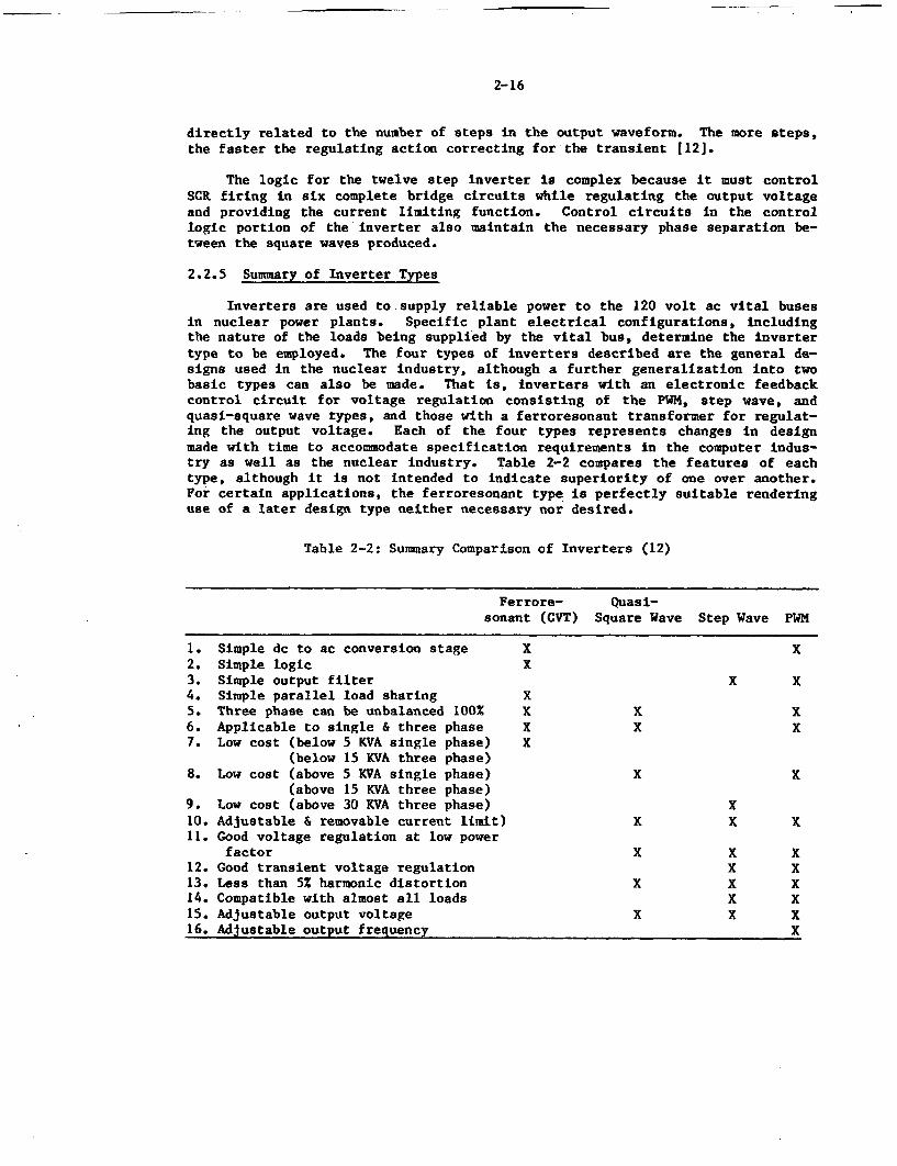
Inverters are used to supply reliable power to the 120 volt ac vital busesin nuclear power plants. Specific plant electrical configurations, includingthe nature of the loads being supplied by the vital bus, determine the invertertype to be employed. The four types of inverters described are the general de-signs used in the nuclear industry, although a further generalization into twobasic types can also be made. That is, inverters with an electronic feedbackcontrol circuit for voltage regulation consisting of the PWM, step wave, andquasi-square wave types, and those with a ferroresonant transformer for regulat-ing the output voltage. Each of the four types represents changes in designmade with time to accommodate specification requirements in the computer indus-try as well as the nuclear industry. Table 2-2 compares the features of eachtype, although it is not intended to indicate superiority of one over another.For certain applications, the ferroresonant type is perfectly suitable renderinguse of a later design type neither necessary nor desired.
Table 2-2: Summary Comparison of Inverters (12)
Ferrore- Quasi-sonant (CVT) Square Wave Step Wave PWM
1. Simple dc to ac conversion stage X X2. Simple logic X3. Simple output filter X X4. Simple parallel load sharing X5. Three phase can be unbalanced 100 X X X6. Applicable to single & three phase X X X7. Low cost (below 5 KVA single phase) X
(below 15 KVA three phase)8. Low cost (above 5 KVA single phase) X X
(above 15 KVA three phase)9. Low cost (above 30 KVA three phase) X10. Adjustable & removable current limit) X X X11. Good voltage regulation at low power
factor X X X12. Good transient voltage regulation X X13. Less than 5% harmonic distortion X X X14. Compatible with almost all loads X X15. Adjustable output voltage X X X16. Adjustable output frequency X
2-17
2.3 Battery Charger and Inverter Components
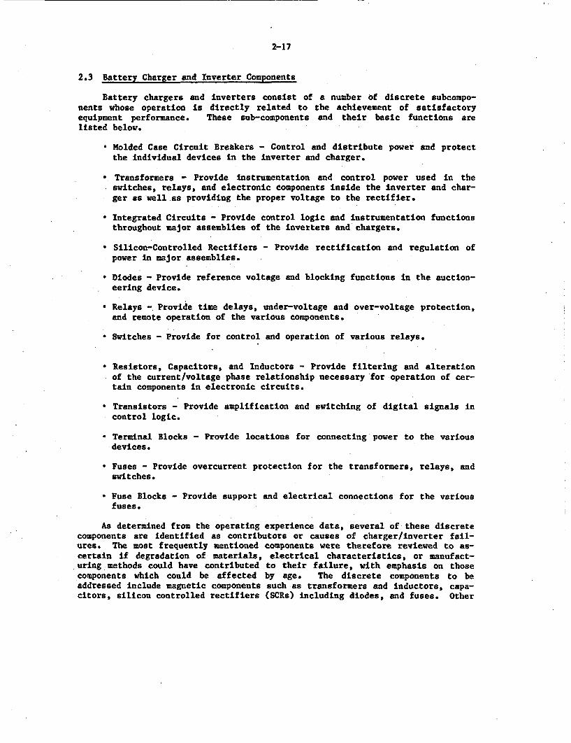
Battery chargers and inverters consist of a number of discrete subcompo-nents whose operation is directly related to the achievement of satisfactoryequipment performance. These sub-components and their basic functions arelisted below.
• Molded Case Circuit Breakers - Control and distribute power and protectthe individual devices in the inverter and charger.
* Transformers - Provide instrumentation and control power used in theswitches, relays, and electronic components inside the inverter and char-ger as well as providing the proper voltage to the rectifier.
Integrated Circuits - Provide control logic and instrumentation functionsthroughout major assemblies of the inverters and chargers.
Silicon-Controlled Rectifiers - Provide rectification and regulation ofpower in major assemblies.
* Diodes - Provide reference voltage and blocking functions in the auction-eering device.
• Relays - Provide time delays, under-voltage and over-voltage protection,and remote operation of the various components.
* Switches - Provide for control and operation of various relays.
* Resistors, Capacitors, and Inductors - Provide filtering and alterationof the current/voltage phase relationship necessary for operation of cer-tain components in electronic circuits.
Transistors - Provide amplification and switching of digital signals incontrol logic.
* Terminal Blocks - Provide locations for connecting power to the variousdevices.
* Fuses - Provide overcurrent protection for the transformers, relays, andswitches.
* Fuse Blocks - Provide support and electrical connections for the variousfuses.
As determined from the operating experience data, several of these discretecomponents are identified as contributors or causes of charger/inverter fail-ures. The most frequently mentioned components were therefore reviewed to as-certain if degradation of materials, electrical characteristics, or manufact-uring methods could have contributed to their failure, with emphasis on thosecomponents which could be affected by age. The discrete components to beaddressed include magnetic components such as transformers and inductors, capa-citors, silicon controlled rectifiers (SCRs) including diodes, and fuses. Other
2-18
components such as resistors, transistors, switches, fuse blocks, and integratedcircuits are not specifically discussed because of their relatively minor indi-vidual contribution to inverter/charger failure. Relays, circuit breakers, andcable are being addressed in detail in other NPAR program studies. Their agingmechanism, if any, will be discussed in those reports. Input from those studieswill be applied to Phase II recommendations, as appropriate.
2.3.1 Magnetic Components
Common to the described inverter and battery charger types are the magneticcomponents, namely transformers and inductors (chokes). Transformers with rat-ings from 10 to 50 KVA are typically found in the battery charger input sectionand in the inverter output following the dc-ac conversion. In addition, smallertransformers may be used for metering or control purposes. Inductors or chokesare commonly used in both chargers and inverters for filtering dc (output ofcharger, input of inverter). They are typically sized in the low millihenryrange at the required dc ampere rating (300 amps is common).
The life of transformers and inductors is directly related to their insula-tion condition. Standards such as IEEE 259-1974, IEEE Standard Test Procedurefor Evaluation of System of Insulation for Specialty Transformers, and IEEE 392-1976, IEEE Recommended Practice for Achieving High Reliability in ElectronicTransformers and Inductors, address the testing requirements for transformersand inductors and focus on the effects of higher ambient temperatures on the in-sulation. Material degradations due to chemical interactions and harmful decomrposition products can also ultimately lead to an insulation brealdown.
Environmental conditions degrade transformers and inductors in the follow-ing manner (13]:
*Maximum operating temperature affects the life of the insulation used.
* Low temperatures can affect the moisture seals and cause then to crack.
* The magnetic core material characteristics can vary with temperature.
* The normal resistance change experienced in the winding wire as thetemperature increases may be about 1.02 for every 1.5°C rise intemperature.
*The temperature limits of the insulation and impregnated materials shouldbe selected to give required life.
•Moisture must be prevented from reaching the winding, otherwise corrosionor serious reduction of dielectric strength or insulation resistance willoccur.
* Insulation between windings or between winding and core or ground canfail in service when subjected to high voltage stress. The effect is tocause local heating and deterioration of the material and results incomplete dielectric failure. Also radio frequency noises are oftengenerated by the electrostatic discharges which may affect the circuitoperation.
2-19
* It is possible for connecting wires between seals 'and coils to fractureunder severe vibration if they are pulled too tight when soldering. Thisshould be detected by the manufacturer during conduct of the acceptancetest procedure.
* Reduction in insulation resistance due to insufficient or poor impregna-tion and consequent penetration of moisture. Once moisture penetrates,there is a progressive building up of moisture which penetrates theenamel on the wire causing the insulation resistance to fall.Degradation is then rapid and the transformer fails.
* Transformer noise caused by loose laminations is generally due to poordesign and/or manufacturing techniques.
A review of a battery charger and inverter qualification reports revealedthat for the main magnetic components, i.e., input/output transformer and filterchoke, a 40 year life was predicted. This 'qualified life' determination wasbased on analysis of the thermal degradation of the insulating materials whichconsists of layer to layer and wire insulation. The coating on the copper mag-netic wire used was classified as 220"C insulation, while the layer to layer in-sulation used was a polyamide polymer classified as class E insulation. Itshould be noted, however, that in the inverter -application, two small trans-formers using a polyamide polymer insulation were recommended to be changed outevery 2.6 years because of the limited life of the mylar tape utilized. There-fore, even though magnetic components consist of copper magnet wire, steel corematerial, and insulation materials, it is the insulation materials which governthe transformer life.
The actual assembly and testing of the magnetics used in class IE batterycharger applications was observed as part of a detailed tour of one manufac-turer's facilities. Periodic checks made during assembly and overvoltage test-ing conducted just before final packaging assures that the straight forwardassembly procedure has been completed properly and that no material defectsexist. Judging by the manner in which this important but standard component ismanufactured, it is unlikely that failures due to fabrication errors will resultin charger or inverter degradation.
However, a recent event associated with ferroresonant transformers (IE InfoNotice 84-84) resulted in degraded inverter operation at a plant in its initialtesting phase. The particular deficiency detected was of a mechanical nature,i.e., the windings were inadequately secured which allowed the center leg toshift and vibrate while energized. This, in turn, caused an insulation break-down between the transformer core and coil. This short circuit resulted in acollapsed voltage output and occurred early in transformer life. Although notdirectly associated with magnetics fabrication, the manner in which the trans-former was supported caused a failure in the magnetics.
As far as inductors are concerned, the performance of a ferrite core induc-tor is governed by the quality of the ferrite. No single grade of ferrite cancover the complete frequency range, so adjustments are usually made by partialshunting of the air gap. To ensure long term stability, a support is usuallynecessary for the shunt, however, the material used must be dimensionally stable
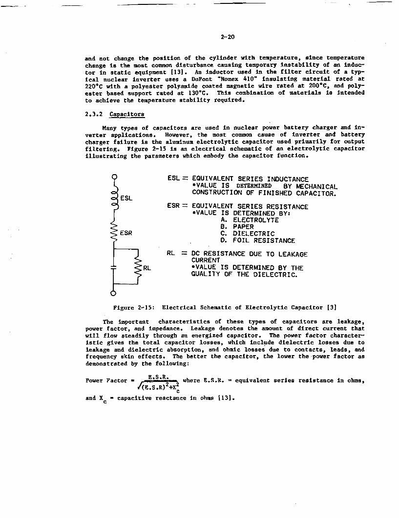
2-20
and not change the position of the cylinder with temperature, since temperaturechange is the most common disturbance causing temporary instability of an induc-tor in static equipment 1131. An inductor used in the filter circuit of a typ-ical nuclear inverter uses a DuPont 'Nomex 410" insulating material rated at220'C with a polyester polyamide coated magnetic wire rated at 200°C, and poly-ester based support rated at 130'C. This combination of materials is intendedto achieve the temperature stability required.
2.3.2 Capacitors
Many types of capacitors are used in nuclear power battery charger and in-verter applications. However, the most common cause of inverter and batterycharger failure is the aluminum electrolytic capacitor used primarily for outputfiltering. Figure 2-15 is an electrical schematic of an electrolytic capacitorillustrating the parameters which embody the capacitor function.
ESL = EQUIVALENT SERIES INDUCTANCE*VALUE IS DETERMINED BY MECHANICAL
ESL CONSTRUCTION OF FINISHED CAPACITOR.
ESR = EQUIVALENT SERIES RESISTANCE*VALUE IS DETERMINED BY:
A. ELECTROLYTEB. PAPER
ESR C. DIELECTRICD. FOIL RESISTANCE
RL = DC RESISTANCE DUE TO LEAKAGECURRENT
RL *VALUE IS DETERMINED BY THEQUALITY OF THE DIELECTRIC.
Figure 2-15: Electrical Schematic of Electrolytic Capacitor 13]
The important characteristics of these types of capacitors are leakage,power factor, and impedance. Leakage denotes the amount of direct current thatwill flow steadily through an energized capacitor. The power factor character-istic gives the total capacitor losses, which include dielectric losses due toleakage and dielectric absorption, and ohmic losses due to contacts, leads, andfrequency skin effects. The better the capacitor, the lower the power factor asdemonstrated by the following:
Power Factor - E.S.R. where E.S.R. - equivalent series resistance in ohms,I(E.S.R) 22XC
and Xc - capacitive reactance in ohms 1131.
2-21
Impedance is introduced in the form of an inductive reactance for the electroly-tic capacitor. In many cases, actual capacitor impedance at the operating fre-quency is a direct indication of capacitor performance.
The life of an electrolytic capacitor in filter applications is proportion-ately related to the core temperature, working voltage, and ripple current. Onemanufacturer of electrolytic capacitors has generated failure rate curves forvarious grades and types of electrolytic capacitors. Based on operation atrated voltage and at the design operating temperature, a life of five to twentyyears is expected based on the different models and configurations used [141.The report also states that the failure rate during this expected life period isa constant or decreasing failure rate. However, no data for failure mechanismssuch as corrosion or outgassing which have been reported to occur in nuclearplant battery chargers and inverters were available. On the basis of the capa-citor manufacturer input, this inverter manufacturer, along with several others,recommends a five year replacement interval for all electrolytic capacitors.
Another manufacturer of ferroresonant type inverters points out in the in-struction manual that even though the oil filled and electrolytic capacitors arerated for more than ten years, application experience indicates a life of onlyfive to seven years. They therefore recommend replacement of these capacitorsevery three to four years.
Similarly, a supplier of a qualified battery charger using a differentelectrolytic capacitor has used specific curves such as the life multipliercurve shown in Table 2-3 to demonstrate an expected life of approximately tenyears. Although this is not considered equivalent to an end of life value, thecharger manufacturer recommends changing out the electrolytic capacitors every10 years. Because the electrolytic capacitor life is sensitive to temperature,voltage and ripple current, longer capacitor life would be achieved by utilizinga capacitor having a higher rated voltage than operating voltage, and ensuringthat the average operating temperature doesn't exceed 55C.
It is also important to note that failure for a capacitor does not meancatastrophic failure. As indicated by one manufacturer's qualification test re-port, failure is defined as a 10% change in capacitance value or an increase inequivalent series resistance (ESR) greater than 175Z of the initial measuredvalue. Another source (131 discussing characteristic changes which occur overlong periods of storage indicates that a 50% capacitance loss, or an increase ofeither power factor or leakage current by a factor of 10 would render the capa-citor unfit for further service. The capacitance value and the equivalentseries resistance are measurable parameters that could be used as an input fordetermining capacitor replacement.
As indicated by Figures 2-16 through 2-18, useful life varies with tempera-ture, voltage, and percent ripple current, respectively, and can be predictedfairly accurately. The useful life is inversely proportional to the appliedvoltage and increases tenfold for every 252 decrease in applied voltage. Con-versely, it decreases by a factor of about 2 for every 10C increase in operat-ing temperature.
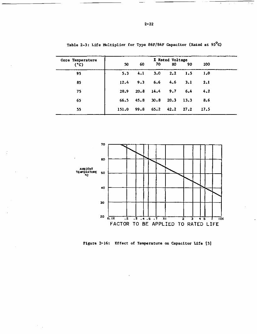
-
2-22
Table 2-3: Life Multiplier for Type 86F/84F Capacitor (Rated at 950C)
Core Temperature 2 Rated Voltage(C) 50 60 70 80 90 100
95 5.3 4.1 3.0 2.2 1.5 1.0
85 12.4 9.3 6.6 4.6 3.1 2.1
75 28.9 20.8 14.4 9.7 6.4 4.2
65 66.5 45.8 30.8 20.3 13.3 8.6
55 151.0 99.8 65.2 42.2 27.2 17.5
70
60
AWI4ENTTEMPERATURE
QC50
0.Jx .2 .3 .4 .5 .7 xi 2 3 4 5 lox
FACTOR TO BE APPLIED TO RATED LIFE
40
30
20
Figure 2-16: Effect of Temperature on Capacitor Life [31
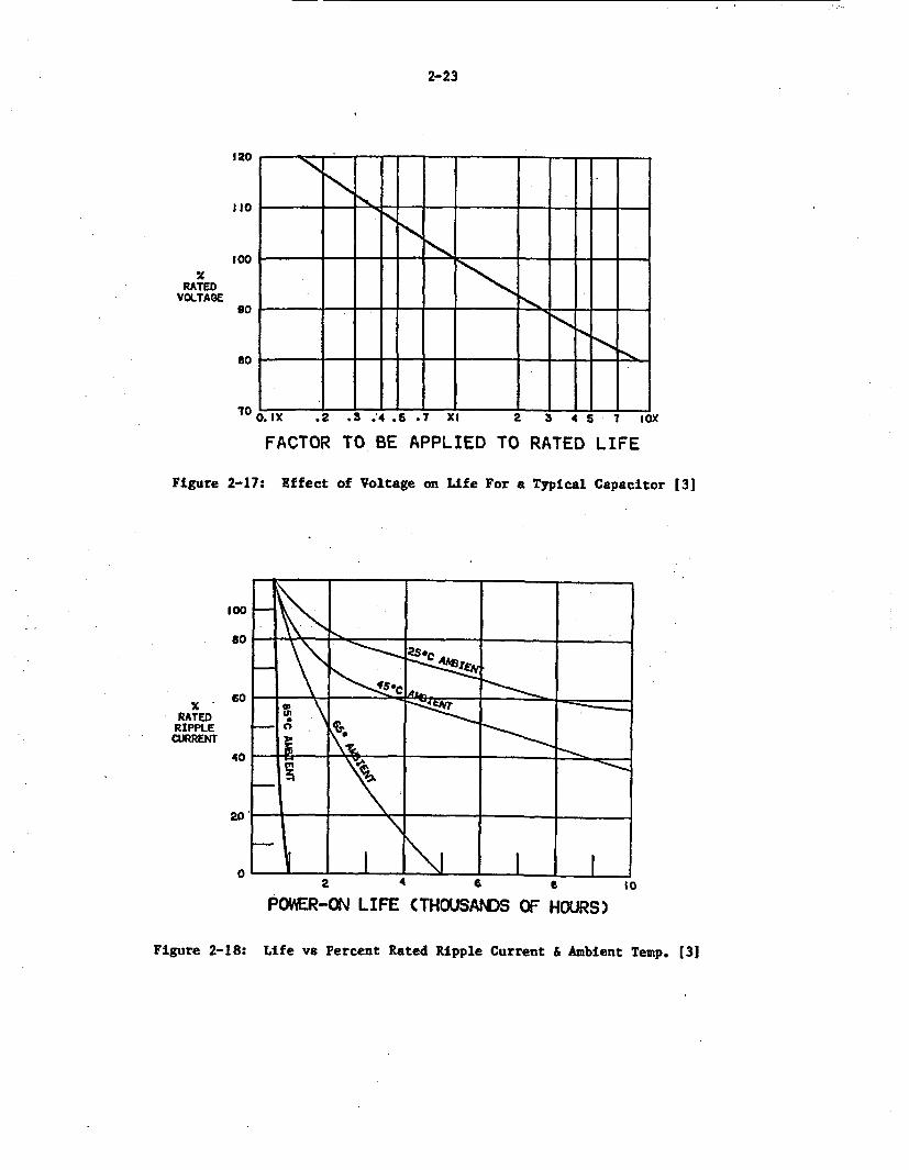
2-23
120
I I
100X
RATEDVOLTAGE
D. IX ,2 .3 .'4 .5 .7 Xi 2 3 4 5 7 10:A
90
so
70 1 K
FACTOR TO BE APPLIED TO
Figure 2-17: Effect of Voltage on Life For a
RATED LIFE
Typical Capacitor (31
100
so
RATEDRIPPLE
CURRENT
60
40 _ - -
20
2 4 6 a so
POWER-ON LIFE (THOUSANDS OF HOURS)
Figure 2-18: Life ve Percent Rated Ripple Current & Ambient Temp. [31
2-24
Other types of capacitors used in battery chargers and inverters are tanta-lum, ceramic, glass, mica, paper, and polyester. An inverter manufacturer'squalification test report states that industry testing on these types of capaci-tors has resulted in the position that they are "insensitive to aging". For in-stance, in tests continuously performed from 1960 to 1972 on polyester (mylar)dielectric capacitors, data were extrapolated to demonstrate a device life wellin excess of 40 years. Similarly, for tantalum capacitors, while some failuresoccurred in the first two hours of testing, continued testing at elevated ter-peratures and voltages demonstrated an expected life of over 100 years. Testingof ceramic capacitors by one capacitor manufacturer indicated that no age re-lated problems should be experienced during the normal operating life of thecharger or inverter. However, they also state that the capacitor life could beincreased significantly if the capacitor is operated at 50% of its rated voltageat ambient temperature.
The primary advantage of an electrolytic capacitor is the large capacitancevalue that can be put in a small case. The capacitance-to-volume ratio islarger for an electrolytic capacitor than for any other type of capacitor 1151.Even though it has a much shorter expected life than other capacitor types,electrolytics are the optimum type of capacitor for low frequency filtering, by-passing, and coupling. For maximum life, the figures presented indicate thatthey should be operated at no greater than 80% of their rated voltages.
2.3.3 Silicon Controlled Rectifiers (SCR) and Silicon Diodes
The Silicon Controlled Rectifier (SCR) is a solid state switch capable ofrectifying alternating current into direct current. Also known as a thyristor,this device has three terminals called the anode, cathode, and gate, schemati-cally displayed in Figure 2-3 and pictorially illustrated in Figure 2-19. Witha reverse voltage applied to its anode-to-cathode terminals (positive cathodevoltage), the device will not conduct any appreciable current. When the anodeis made positive with respect to the cathode, and a small positive voltage pulseis applied across the gate-to-cathode terminals the device switches on. Oncethe SCR is conducting, the gate signal is no longer required to maintain theswitch in the on condition. The SCR will continue to conduct until the currentfalls below the holding current level or the current is reversed as is automat-ically done in alternating current. The conducting time is typically controlledby an. external circuit in a battery charger or inverter called the firingmodule. Degradation of the firing module output will affect the SCR conductingtime, thereby rendering the current output uncontrollable and the charger/inver-ter inoperable.
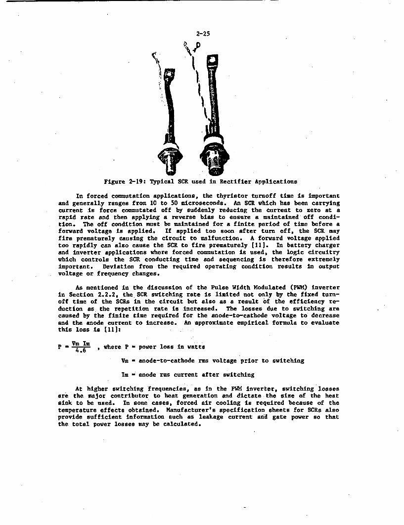
2-25
II,
Figure 2-19: Typical SCR used in Rectifier Applications
In forced commutation applications, the thyristor turnoff time is importantand generally ranges from 10 to 50 microseconds. An SCR which has been carryingcurrent is force commutated off by suddenly reducing the current to zero at arapid rate and then applying a reverse bias to ensure a maintained off condi-tion. The off condition must be maintained for a finite period of time before aforward voltage is applied. If applied too soon after turn off, the SCR mayfire prematurely causing the circuit to malfunction. A forward voltage appliedtoo rapidly can also cause the SCR to fire prematurely (111. In battery chargerand inverter applications where forced commutation is used, the logic circuitrywhich controls the SCR conducting time and sequencing is therefore extremelyimportant. Deviation from the required operating condition results in outputvoltage or frequency changes.
As mentioned in the discussion of the Pulse Width Modulated (PWK) inverterin Section 2.2.2, the SCR switching rate is limited not only by the fixed turn-off time of the SCRs in the circuit but also as a result of the efficiency re-duction as the repetition rate is increased. The losses due to switching arecaused by the finite time required for the anode-to-cathode voltage to decreaseand the anode current to increase. An approximate empirical formula to evaluatethis loss is 1111:
4.6 , where P - power loss in watts
Vm - anode-to-cathode rms voltage prior to switching
Im - anode rms current after switching
At higher switching frequencies, as in the PWM inverter, switching lossesare the major contributor to heat generation and dictate the size of the heatsink to be used. In some cases, forced air cooling is required because of thetemperature effects obtained. Manufacturer's specification sheets for SCRs alsoprovide sufficient information such as leakage current and gate power so thatthe total power losses may be calculated.
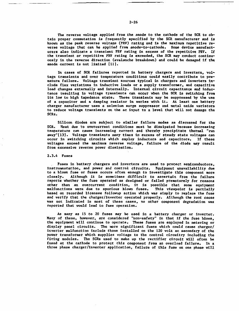
2-26
The reverse voltage applied from the anode to the cathode of the SCR to ob-tain proper commutation is frequently specified by the SCR manufacturer and isknown as the peak reverse voltage (PRY) rating and is the maximum repetitive re-verse voltage that can be applied from anode-to-cathode. Some device manufact-urers also indicate a transient PRV rating in excess of the repetitive PRV. Ifthe transient or repetitive PRV rating is exceeded, the SCR may conduct continu-ously in the reverse direction (avalanche breakdown) and could be damaged if theanode current is not limited [111.
In cases of SCR failures reported in battery chargers and inverters, vol-tage transients and over temperature conditions could easily contribute to pre-mature failure. Voltage transient sources typical in chargers and inverters in-clude flux variations in inductive loads or a supply transformer, and capacitiveload changes externally and internally. Internal circuit capacitance and induc-tance resulting in voltage transients can occur when the SCR is switching fromits low to high impedance state. These transients may be suppressed by the useof a capacitor and a damping resistor in series with it. At least one batterycharger manufacturer uses a selenium surge suppressor and metal oxide varistorsto reduce voltage transients on the ac input to a level that will not damage theSCRa.
Silicon diodes are subject to similar failure modes as discussed for theSCR. Reat due to overcurrent conditions must be dissipated because increasingtemperature can cause increasing current and thereby precipitate thermal "runaway"[131. Voltage transients many times in excess of steady state voltages canoccur in switching circuits which employ inductors and capacitors. If thesevoltages exceed the maximum reverse voltage, failure of the diode may resultfrom excessive reverse power dissipation.
2.3.4 Fuses
Fuses in battery chargers and inverters are used to protect semiconductors,instrumentation, and power and control circuits. Equipment unavailability dueto a blown fuse or fuses occurs often enough to investigate this component moreclosely. Although it is sometimes difficult to ascertain from the failurereports whether the fuse operated as designed or failed prematurely for reasonsother than an overcurrent condition, it is possible that some equipmentmalfunctions were due to spurious blown fuses. This viewpoint Is partiallybased on recorded licensee followup action which was simply to replace the fuseand verify that the charger/inverter operated properly. Although the root causewas not indicated in most of these cases, no other component degradation wasreported that would lead to fuse operation.
As many as 15 to 20 fuses may be used in a battery charger or inverter.Many of these, however, are considered "non-safety" in that if the fuse blows,the equipment will continue to operate. These fuses are employed in metering ordisplay panel circuits. The more significant fuses which could cause charger/inverter malfunction include those installed on the 120 volt ac secondary of thepower transformer which supplies voltage to the control circuitry including thefiring modules. The SCRs used to make up the rectifier circuit will often befused at the cathode to protect this component from an overload failure. In athree phase charger/inverter application, failure of this fuse on one phase will
2-27
result in overload conditions on the two unaffected phases and ultimately tripthe input circuit breaker. Fuses are sometime installed in series with the out-put filters. A blown fuse in this portion of the circuit may not directlyresult in a charger/inverter trip, but could cause output problems due to adistorted waveform. One particular design also contains current limiting fuseslocated in the circuit between the transformer secondary and the rectifierdiodes. Care must be taken to replace these fuses with exact duplicates in typeand rating In order to ensure equipment protection.
IEEE Standard 650-1979 161 for the qualification of chargers and invertersstates that fuses which have been properly applied in circuits with respect toampacity, voltage, and temperature have no age related common mode failure mech-anisms. Temperature is the important factor to consider in that a temperaturerise at the fuse or fuse holder termination will have the same effect on thefuse as an overload condition.
In contradiction to the above is the belief that fuse failure due to ther-mal fatigue is a possibility [31. The only evidence of this found in the datareviewed was an inverter failure due to a fuse failure in 1983. Analysis by theutility indicated that because the fuse failed at the cap rather than in thelink itself, it was possible that the fuse was defective which eventually led toa thermal fatigue failure. This potential age related failure mode will be in-vestigated further in the Phase 2 Study.
2.4 Battery Charger/Inverter Plant Configurations
In addition to the different types and sizes of battery chargers and inver-ters, one must also consider the arrangement of the equipment in order to assessaging and service wear effects at a plant safety level. Rather than analyzing a'typical' nuclear power plant, it was decided to examine a number of actualplants. For battery chargers, the bus configurations of 23 nuclear plants werecompiled and are listed in Table 2-4. As illustrated, the nuclear system sup-pliers are all represented as are plants of various ages. Plants with no LERsas well as plants with many LERs were selected and are listed by plant type inthis table.
A wide variation in battery charger configurations was found to exist, in-cluding two dc buses with one charger per bus and no standby as shown in Figure2-20, two full capacity chargers per bus with no standby charger as depicted byFigure 2-21, and four dc buses having one charger per bus along with standbycapability as illustrated in Figure 2-22. These configurations, along with theinfrequently used arrangement of a standby charger in conjunction with two fullcapacity chargers per bus, are summarized in Table 2-5, indicating.the number offailures that have been documented by LERs and the accumulated number of reactoroperating years of the plants using these designs. Note the addition of astandby charger or a second full capacity charger dramatically reduces the num-ber of issued LERs. Even more important, of course, is the obvious improvementin plant safety achieved by these arrangements due to the increased reliabilityof maintaining the batteries in a fully charged condition, given a charger fail-ure. The ability to place a standby charger in service or quickly have a redun-dant charger pick up the load when a failure occurs results in minimal batterydepletion.
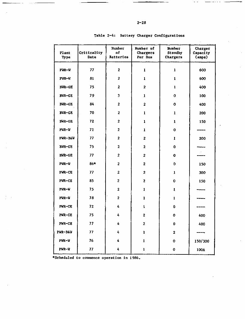
2-28
Table 2-4: Battery Charger Configurations
Number Number of Number ChargerPlant Criticality of Chargers Standby CapacityType Date Batteries Per Bus Chargers (amps)
PWR-W
PWR-W
BWR-GE
BWR-GE
BWR-GE
BWR-GE
BWR-GE
PWR-W
PWR-B&W
BWR-GE
BWR-GE
PWR-W
PWR-CE
PWR-CE
PWR-W
PWR-W
PWR-CE
PWR-CE
PWR-CE
PWR-B&W
PWR-W
PWR-W
77
81
75
79
84
70
72
71
77
75
77
86*
77
85
75
78
72
75
77
77
76
77
2
2
2
3
2
2
2
2
2
2
2
2
2
2
2
2
44
4
4
4
4
1
1
2
1
2
1
1
1
2
2
2
2
2
2
1
1
1
2
2
1
1
1
1
11
0
0
1
I
0
1
0
0
0
I
0
1
1
0
0
0
2
0
0
600
600
400
100
400
200
150
200
150
300
150
1!
400
400
5O/300
lOOA_
*Scheduled to commence operation in 1986.
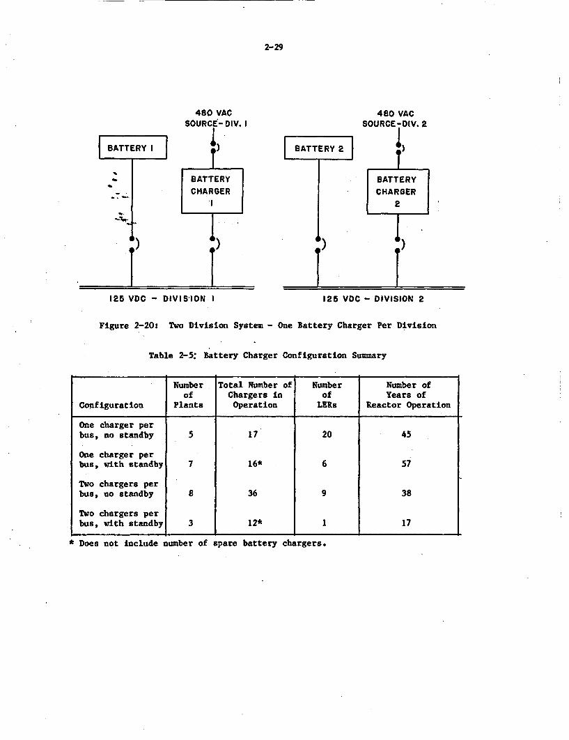
2-29
480 VAC 480 VACSOURCE-DIV. 2,I
BATTERY I
9 )
BATTERY 2
F)iA)
I126 VDC - DIVISION I 125 VDC - DIVISION 2
Figure 2-20: Two Division System - One Battery Charger Per Division
Table 2-5: Battery Charger Configuration Summary
Number Total Number of Number Number ofof Chargers in of Years of
Configuration Plants Operation LERs Reactor Operation
One charger perbus, no standby 5 17 20 45
One charger perbus, with standby 7 16* 6 57
Two chargers perbus, no standby 8 36 9 38
Two chargers perbus, with standby 3 12* 1 17
* Does not include number of spare battery chargers.
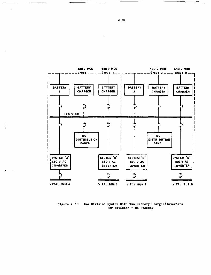
2-30
480 V MCC 480 V MCC 480 V MCC 480 V MCC…---- -Group I____Group I… -------- Group 2--- Group 2 -
I BATTERY BATTERY ATTERY 13ATTERY BATTERY BATTERY II | CHARGER C 2 CHARGER CHARGER |I 111
Ij I
1 125'
I T
I )
I SYSTE'M 'A'L120 V AC
INVERTER
V ITA L BUS A
IV DC I
DCDISTRIBUTION
PANEL
)
SYSTEM 'C' SYSTEM B'120 V AC 120 V ACINVERTER INVERTER
VITAL BUS C VITAL BUS E
4)
DCIDISTRIBUTION4
PANELI
-I
I
SYSTEM BD120 V AC] INVERTER
L)
I VITAL BUS D
Figure 2-21: Two Division System With Two Battery Charger/InvertersPer Division - No Standby
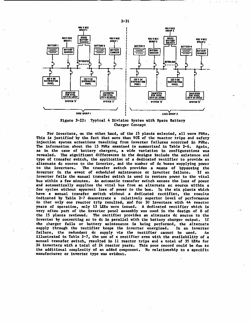
2-31
SYSTEM C SYSTEM '' SYSTE ST
V I VLOAD SROUP I | LOAD GROUP I
Figure 2-22: Typical 4 Division System with Spare BatteryCharger Concept
For inverters, on the other, hand, of the 15 plants selected, all were PWRs.This is justified by the fact that more than 90X of the reactor trips and safetyinjection system actuations resulting from inverter failures occurred in PWRs.The information about the 15 PWRs examined is summarized in Table 2-6. Again,as in the case of battery chargers, a wide variation in configurations wasrevealed. The significant differences In the designs include the existence andtype of transfer switch, the application of a dedicated rectifier to provide analternate dc source to the inverter, and the number of dc buses supplying powerto the inverters. The transfer switch provides a means of bypassing theinverter in the event of scheduled maintenance or inverter failure. If aninverter fails the manual transfer switch is used to restore power to the vitalbus within a few minutes. An automatic transfer switch senses the loss of powerand automatically supplies the vital bus from an alternate ac source within afew cycles without apparent loss of power to the bus. In the six plants whichhave a manual transfer switch without a dedicated rectifier, the resultsindicated by Table 2-7 demonstrate a relatively superior level of performancein that only one reactor trip resulted, and for 30 inverters with 44 reactoryears of operation, only 13 LERs were issued. A dedicated rectifier which isvery often part of the inverter panel assembly was used in the design of 8 ofthe 15 plants reviewed. The rectifier provides an alternate dc source to theinverter by converting ac to dc in parallel with the battery charger output. Ifthe charger fails or battery maintenance is being performed, the alternatesupply through the rectifier keeps the inverter energized. In an inverterfailure, the redundant dc supply via the rectifier cannot be used. Asillustrated in Table 2-7, the use of a rectifier even with the availability of amanual transfer switch, resulted in 11 reactor trips and a total of 35 LERs for24 inverters with a total of 24 reactor years. This poor record could be due tothe additional complexity of an added component. No relationship to a specificmanufacturer or Inverter type was evident.
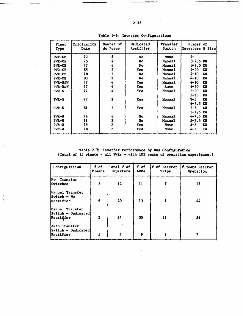
-
2-32
Table 2-6: Inverter Configurations
Plant Criticality Number of Dedicated Transfer Number ofType Date dc Buses Rectifier Switch Inverters & Size
PR-CE 72 4 No None 4-PWR-CE 75 4 No Manual 8-7.5 KWPWR-CE 77 4 No Manual 8-7.5 KWPWR-CE 85 2 Yes Manual 4-20 KWPWR-CE 78 2 No Manual 4-10 KWPWR-CE 83 2 No Manual 4-10 KWPWR-B&W 77 4 Yes Manual 4-10 KWPWR-B&W 77 4 Yes Auto 4-30 KWPWR-W 77 4 Yes Manual 2-20 KW
2-25 KWPWR-W 77 2 Yes Manual 2-5 KW
4-7.5 KWPWR-W 81 2 Yes Manual 2-5 KW
2-7.5 KWPWR-W 76 4 No Manual 4-7.5 KWPWR-W 71 2 No Manual 2-7.5 KWPWR-W 75 2 Yes None 4-5 KWPWR-W 78 2 Yes None 4-5 KW
Table 2-7: Inverter Performance by Bus Configuration(Total of 15 plants - all PWRs - with 102 years of operating experience.)
Configuration # of Total $ of I of I of Reactor 1 Years ReactorPlants Inverters LERs Trips Operation
No TransferSwitches 3 12 11 7 27
Manual TransferSwitch - NoRectifier 6 20 13 1 44
Manual TransferSwitch - DedicatedRectifier 5 24 35 11 24
Auto TransferSwitch - DedicatedRectifier 1 4 9 3 7
2-33
The number of de buses varied as well with 8 of the 15 units using a twobus design and 7 using a four bus design. Except for one case where only twoinverters exist, the remaining plants reviewed have at least four inverters withas many as eight inverters existing in two of the units. There was nocorrelation between the number of existing buses and the failure data, however,it is apparent that the more buses existing, the better the separation of deloads can be. With a four bus. design, the likelihood of one de bus causingmultiple system failures is reduced.
3-1
3.0 OPERATIONAL STRESSORS AND CORRELATION WITH ACCIDENT SCENARIOS
One of the goals of the NPAR Program is to examine the impact of equip-ment aging on the capability of plant safety systems to mitigate the conse-quences of accident and transient events. In general, a study of the effectsof equipment degradation on the loss of the plant's ability to achieve a safeshutdown condition must include an evaluation of the accident caused stressesthat are imposed on the equipment, as well as the potential for the failure ofan aged equipment to initiate such a transient. This section of the reportexamines the various stresses placed on battery chargers and inverters duringnormal and transient conditions at both the system and component levels, anddescribes the impact that these stresses have on the aging process and theperformance of an aged equipment.
Before describing the effect on safety of these stresses, it is importantto emphasize the significance of the battery charger and the inverter inachieving safe nuclear power plant operation.
The battery charger and the battery are the two principal components ofthe do system. The dc system is the direct source of power for systems suchas Righ Pressure Coolant Injection (HPCI) and Reactor Core Isolation Cooling(RCIC) in a BWR and Auxiliary Feedwater (AFW) in a PWR, and provides controlpower for circuit breaker operation and for instrumentation and logic relaysin both BWRs and MsR. A partial loss of dc power, as documented by actualoccurrences, may cause reactor and turbine trips and can impair the operator'sability to respond to the resulting transient because of a loss of indicatinginstrumentation, controls, and/or annunciation. For instance, the loss of oneof two redundant and independent do buses at a PWR [161 had the following con-sequences:
* reactor trip* total loss of control room annunciation* inability to trip the turbine generator* loss of important control room indication* inadvertent start and subsequent trip of an Emergency Diesel
Generator (EDG)trip of instrument power supplies making it 'difficult foroperators to control the reactor"
A similar event at a second PNR 116) also resulted in a reactor trip anda loss of control room annunciation. In addition, the unit experienced anemergency safeguards actuation and an EDG fire due to prolonged generatoroverload. Reactor operation in the natural circulation mode was necessaryduring this event.
A system interaction study of a Westinghouse PWR performed by BNL for theNRC (171 discovered that the loss of one dc bus would prevent automatic actua-tion of low pressure injection subsystems following a LOCA event involving apartial loss of of f site ac power. This was due to the use of dc for circuitbreaker control power and bus transfer logic schemes which rendered two trainsof RHR inoperable.
3-2
The preceding paragraphs emphasize the complex plant interaction involvedwith the dc system of which the charger is an integral part. A catastrophicor degraded battery charger failure which is not detected and corrected in atimely manner could result in depletion of its associated battery and a par-tial loss of station de power as described above. Similarly, if the batterycharger failure occurs at the time of the transient condition, the plant'sability to achieve a long term safe shutdown condition could be significantlyimpaired.
Inverters are employed to assure continuous power to essential componentseven in the event of a loss of offsite and onsite ac power. Particularly inplants with only two vital ac buses, single inverter failures have initiatedreactor trips and safety system actuations. In addition, important safetyrelated systems such as HPCI, RCIC, and Low Pressure Coolant Injection (LPCI)have been made inoperable by inverter failures. If they should occur underaccident conditions when maximum loads may be applied, inverter failures wouldseverely impair the ability of the operator to respond since instrumentationand controls affecting emergency system operation could be inoperable, provid-ing either no information or iisinformation about important reactor para-meters. Actual challenges to safety systems, approximately 50 in number, haveincluded feedwater system excursions which have resulted in reactor tripsand/or safety injection system actuations. These significant transients placea demand on the safety systems. and the operating personnel, especially whenadditional circumstances develop, such as steam line isolation or inadvertentopening of steam dump valves. Four examples of actual events are depicted toindicate the safety implications of inverter failure.
A reactor trip, safety injection, and steam line isolationoccurred as a result of an inverter failure.
An inverter failure resulted in a reactor trip and safety sys-tem injection which was complicated by the inadvertent openingof the condenser steam dump valves.
An inverter failure also interrupted power to the pressurizerpressure controller rendering both shutdown cooling loops in-operable.
Two feedwater pumps tripped because of a loss of speed controlresulting in a reactor trip and safety system injection.
3.1 System Level Stresses
The battery charger and inverter are closely coupled in most nuclearplant applications and are therefore subjected to a very similar system levelstresses. That is, the charger output is normally connected to the inverterinput, and the ac supply to the battery charger also provides alternate powerto the vital bus, either directly or through a rectifier in the invertermodule. This is illustrated in Figure 3-1 which also depicts the alignment ofoffsite and onsite emergency ac sources.
3-3
System level stresses which could accelerate inverter and charger agingresulting in equipment failure or degradation include the following:
* loss of ac power* accident conditions* electrical disturbances during normal operation
Each of these stresses will be discussed in the subsequent paragraphs.
3.1.1 Lose of ac Power
An extended loss of offsite power coupled with a loss of onsite ac powerplaces loading stress on both the charger and the inverter. During the lossof ac power event, the battery charger is deenergized and the station batteryprovides the input to the dc bus which supplies the dc loads including theInverter. While the inverter load remains fairly constant during this event,load changes on the dc bus due to the startup of the standby motors and ini-tiation of switching operations cause dc voltage transients (reductions) onthe inverter input with a duration ranging from a cycle to several seconds.This type of transient is similar to ones associated with short circuits,transmission system disturbances, and large motor starts. The inverter cir-cuitry is designed to maintain a constant ac voltage with a dc input as low as105 volts, however, fast control and firing module responses are required toobtain this goal under this type of transient condition. SCRs and transis-tors, the primary components providing the control function, must sense thevoltage dip and increase the firing rate to maintain the required output para-meters. Overcompensation by these modules could cause a high voltage invertertrip. Similarly, the input current of the inverter rises as the dc voltagedecreases to provide a constant power output. A momentary decrease in dc busvoltage could result in sufficiently high currents to cause operation of acircuit breaker, or a fast-acting thyristor fuse. Either of these operationswould render the inverter inoperable or degraded.
When ac power is restored, the battery charger must be capable of supply-ing sufficient dc power to supply all of the dc loads while recharging thedepleted battery. Current limiting circuitry prevents the charger from exceed-ing its overload rating of 115 to 125% of capacity. However, even this amountof overload causes stresses which could result in delayed effects includingthe premature failure of electrical components such as fuses, capacitors, andSCRs which are all susceptible to the high temperature conditions producedduring charger overload.
An attempt was made to correlate inverter and battery charger failures tosignificant loss of offsite power events which have occurred at a number ofsites. In the cases reviewed, emergency diesel generator operation restoredpower to the ac bus thereby reducing, if not eliminating, the stresses result-ing from a total loss of ac power previously described. The event descrip-tions did not indicate detailed plant configurations during the event such asmotor control center load shedding which, in some plants, will intentionallymake the charger inoperable unless manual action is taken to restore power tothat bus. Some examples of charger/inverter failure events possibly relatedto loss of offsite power events are denoted in Figure 3-2.
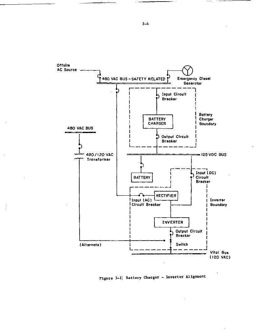
3-4
OffsiteAC Source
(I480 VACI BUS -SAFETY RELATED Emergency Diesel- ~ Generator
1, r--1--I Input Circuiti ') Breoker II II 1I II BATTERY II CHARGER I
I I
I -) Output Circuit II Breoker I
I _ _ _ _ ._ - - - - - -_J
480 VAC BUS
I 480/-- ' T,
BatteryChargerBoundary
= 125 VDC BUS120 VAC;former
-
r Iun1
I I iI|[BATTRY | i
Input (DC)) Circuit
EBreaker-…J
-~ IER I
I InverterI Boundary
3 I
Output Circuit IBreaker I
Switch II-____
TlIIIp
(Alternate ) iLI
Vital Bus(120 VAC)
Figure 3-1: Battery Charger - Inverter Alignment
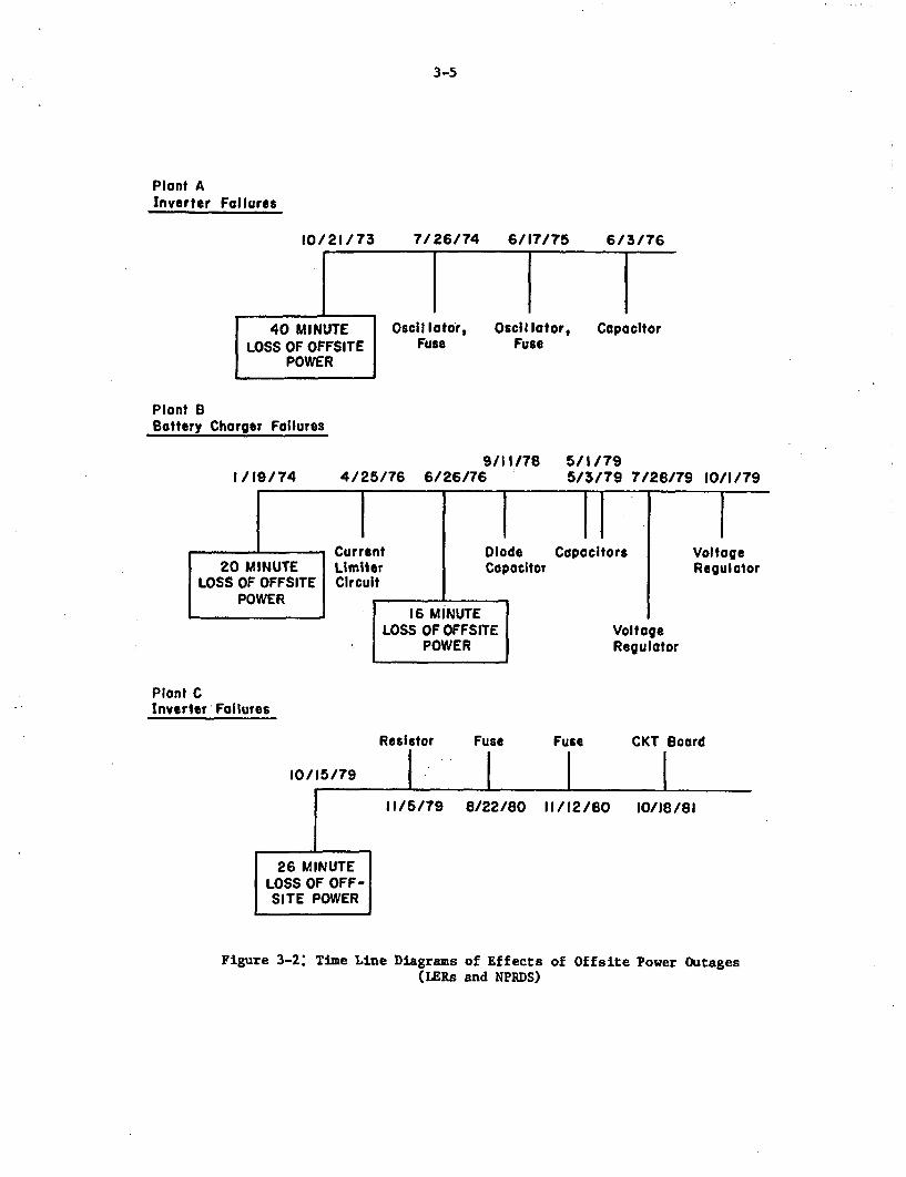
3-5
Plant AInverter Failures
10/21/ 73 7/26/74 6/17/75 6/3/76. .
40 MINUTELOSS OF OFFSITE
POWER
_ O0c11 Ictor, Oscil lotor, CapacitorFuse Fuse
Plant BBattery Charger Failures
9/11/78 5/1/794/25/76 6/26/76 5/3/79 7/28/791/19/74 10/1/79
WCurrent20 MINUTE Limiter
LOSS OF OFFSITE CircuitPOWER _
DiodeCapacitor
. . .
I ICapacitors
1-VoltageRegulator
16 MINUTE.OSS OF OFFSITE
POWERVoltageRegulator
Plant CInverter Failures
Resistor Fuse Fuse CKT Board
10/15/79
26 MINUTELOSS OF OFF-SITE POWER
11/5/79 8/22/80 11/12/80 10/18/81
Figure 3-2: Time Line Diagrams of Effects of Offaite Power Outages(LERs and NPRDS)
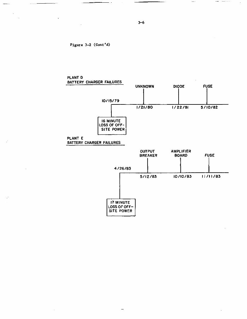
3-6
Figure 3-2 (Cont'd)
PLANT DBATTERY CHARGER FAILURES
UNKNOWN DIODE FUSE
10/15/79 ll
1/21/80 1/022/81 5/10/82
16 MINUTELOSS OF OFF-
SITE POWER
PLANT EBATTERY CHARGER FAILURES
OUTPUT AMPLIFIERBREAKER BOARD FUSE
4/26/83 ll
5/12/83 10/10/83 1 1/11/83
17 MlINUTELOSS OF OFF-SITE POWER
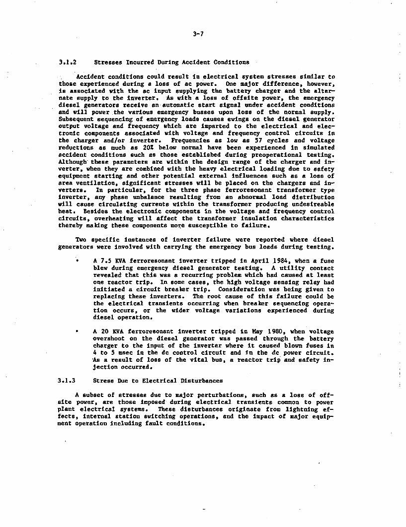
3-7
3.1.2 Stresses Incurred During Accident Conditions
Accident conditions could result In electrical system stresses similar tothose experienced during a loss of ac power. One major difference, however,is associated with the ac input supplying the battery charger and the alter-nate supply to the inverter. As with a loss of offeite power, the emergencydiesel generators receive an automatic start signal under accident conditionsand will power the various emergency busses upon loss of the normal supply.Subsequent sequencing of emergency loads causes swings on the diesel generatoroutput voltage and frequency which are imparted to the electrical and elec-tronic components associated with voltage and frequency control circuits inthe charger and/or inverter. Frequencies as low as 57 cycles and voltagereductions as much as 20% below normal have been experienced in simulatedaccident conditions such as those established during preoperational testing.Although these parameters are within the design range of the charger and in-verter, when they are combined with the heavy electrical loading due to safetyequipment starting and other potential external influences such as a loss ofarea ventilation, significant stresses will be placed on the chargers and In-verters. In particular, for the three phase ferroresonant transformer typeinverter, any phase unbalance resulting from an abnormal load distributionwill cause circulating currents within the transformer producing undesireableheat. Besides the electronic components in the voltage and frequency controlcircuits, overheating will affect the transformer insulation characteristicsthereby making these components more susceptible to failure.
Two specific instances of inverter failure were reported where dieselgenerators were involved with carrying the emergency bus loads during testing.
* A 7.5 KVA ferroresonant Inverter tripped in April 1984, when a fuseblew during emergency diesel generator testing. A utility contactrevealed that this was a recurring problem which had caused at leastone reactor trip. In some cases, the high voltage sensing relay hadinitiated a circuit breaker trip. Consideration was being given toreplacing these inverters. The root cause of this failure could bethe electrical transients occurring when breaker sequencing opera-tion occurs, or the wider voltage variations experienced duringdiesel operation.
* A 20 KVA ferroresonant inverter tripped in May 1980, when voltageovershoot on the diesel generator was passed through the batterycharger to the input of the inverter where it caused blown fuses in4 to 5 msec in the dc control circuit and In the dc power circuit.As a result of loss of the vital bus, a reactor trip and safety in-jection occurred.
3.1.3 Stress Due to Electrical Disturbances
A subset of stresses due to major perturbations, such as a loss of off-site power, are those imposed during electrical transients common to powerplant electrical systems. These disturbances originate from lightning ef-fects, internal station switching operations, and the impact of major equip-ment operation including fault conditions.
3-8
A review of the LE.R and NPRDS data banks revealed that "electrical trans-
ient' was listed as the cause of 29 inverter failures and five battery chargerfailures. In a large majority of these events, circuit breaker and/or fuseoperation occurred which prevented further immediate damage to the inverter/charger circuitry. However, the component was unavailable until power wasrestored by replacing the fuse or closing the circuit breaker. Only eightcases were noted where the transient directly resulted in a component failure,with capacitors and SCRs being most susceptible to this type of occurrence.This breakdown is illustrated by Figure 3-3.
Component Failure
Fuse
Circuit Breaker
SCR
Capacitor
Circuit Breaker
Diode
Unknown
(15)
1 (11)
I((3)
- (4)
lZ(2)
Z (2)
1(3)
I I I -I0 3 6 9 12 15
Number of Failures
Figure 3-3: Component Failures Due to System Electrical Disturbances(LER and NPRDS Data 1974-1984)
(Inverters and Battery Chargers]
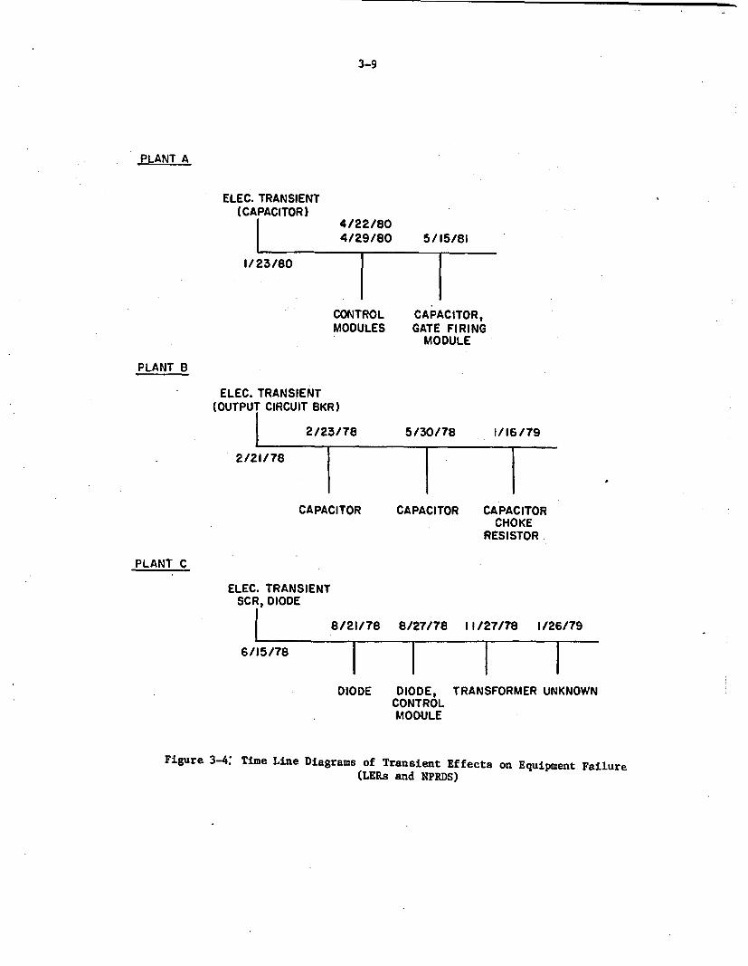
3-9
PLANT A
ELEC. TRANSIENT(CAPACITOR)
I
4/22/804/29/80 5/15/81
1/23/80
CONTROL CAPACITOR,MODULES GATE FIRING
MODULE
PLANT B
ELEC. TRANSIENT(OUTPUT CIRCUIT BKR)
2/23/78 5/30/78 1/16/79
2/21/78
CAPACITORCHOKE
RESISTOR
CAPACITOR CAPACITOR
PLANT C
ELEC. TRANSIENTSCR, DIODE
L 8/21/78 8/27/78 11/27/78 1/26/79
6/15/78
I I I IDIODE DIODE,
CONTROLMODULE
TRANSFORMER UNKNOWN
Figure 3-4: Time Line Diagrams of Transient Effects on Equipment Failure(LERs and NPRDS)
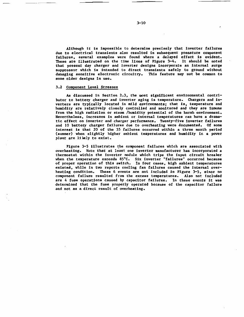
3-10
Although it is impossible to determine precisely that inverter failuresdue to electrical transients also resulted in subsequent premature componentfailures, several examples were found where a delayed effect is evident.These are illustrated on the time lines of Figure 3-4. It should be notedthat present day charger and inverter designs incorporate an internal surgesuppressor which is intended to direct transients safely to ground withoutdamaging sensitive electronic circuitry. This feature may not be common tosome older designs in use.
3.2 Component Level Stresses
As discussed in Section 2.3, the most significant environmental contri-butor to battery charger and inverter aging is temperature. Chargers and in-verters are typically located in mild environments; that is, temperature andhumidity are relatively closely controlled and monitored and they are immunefrom the high radiation or steam /humidity potential of the harsh environment.Nevertheless, increases in ambient or internal temperatures can have a drama-tic effect on inverter and charger performance. Twenty-five Inverter failuresand 10 battery charger failures due to overheating were documented. Of someinterest is that 20 of the 35 failures occurred within a three month period(summer) when slightly higher ambient temperatures and humidity in a powerplant are likely to exist.
Figure 3-5 illustrates the component failures which are associated withoverheating. Note that at least one inverter manufacturer has incorporated athermostat within the inverter module which trips the input circuit breakerwhen the temperature exceeds 85C. Six inverter "failures" occurred becauseof proper operation of this switch. In four cases, high ambient temperaturesexisted, while in two reports cooling fan failures caused the internal over-heating condition. These 6 events are not included in Figure 3-5, since nocomponent failure resulted from the excess temperatures. Also not includedare 4 fuse operations caused by capacitor failures. In these events it wasdetermined that the fuse properly operated because of the capacitor failureand not as a direct result of overheating.
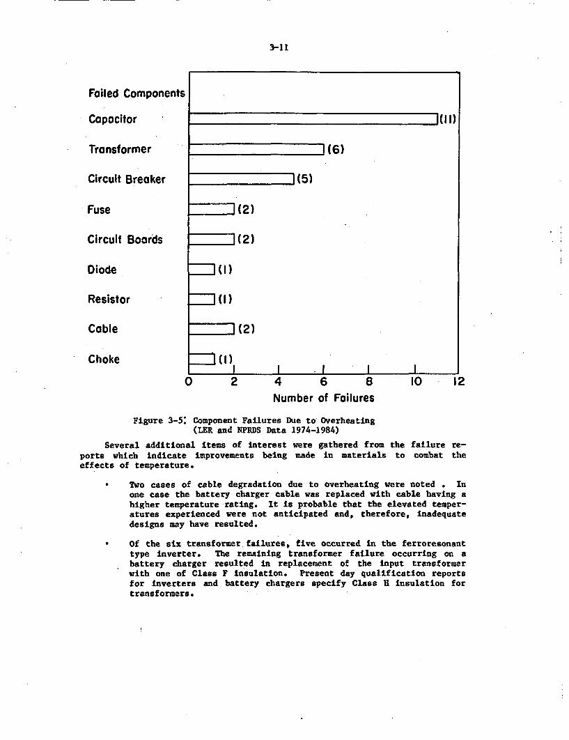
3-11
Failed Components
Capacitor
Transformer
Circuit Breaker
Fuse
Circuit Boards
Diode
Resistor
Cable
Choke
(I 1)
1(6)
z (5)
I (2)
1(2)
=1(1)
=1(1)
I (2)
I( )I . I l
0 2 4 6 8 10 12Number of Failures
Figure 3-5: Component Failures Due to Overheating(LER and NPRDS Data 1974-1984)
Several additional items of interest were gathered from theports which indicate improvements being made in materials toeffects of temperature.
failure re-combat the
* Two cases of cable degradation due to overheating were noted . Inone case the battery charger cable was replaced with cable having ahigher temperature rating. It is probable that the elevated temper-atures experienced were not anticipated and, therefore, inadequatedesigns may have resulted.
* Of the six transformer failures, five occurred in the ferroresonanttype inverter. The remaining transformer failure occurring on abattery charger resulted in replacement of the input transformerwith one of Class F insulation. Present day qualification reportsfor inverters and battery chargers specify Class H insulation fortransformers.
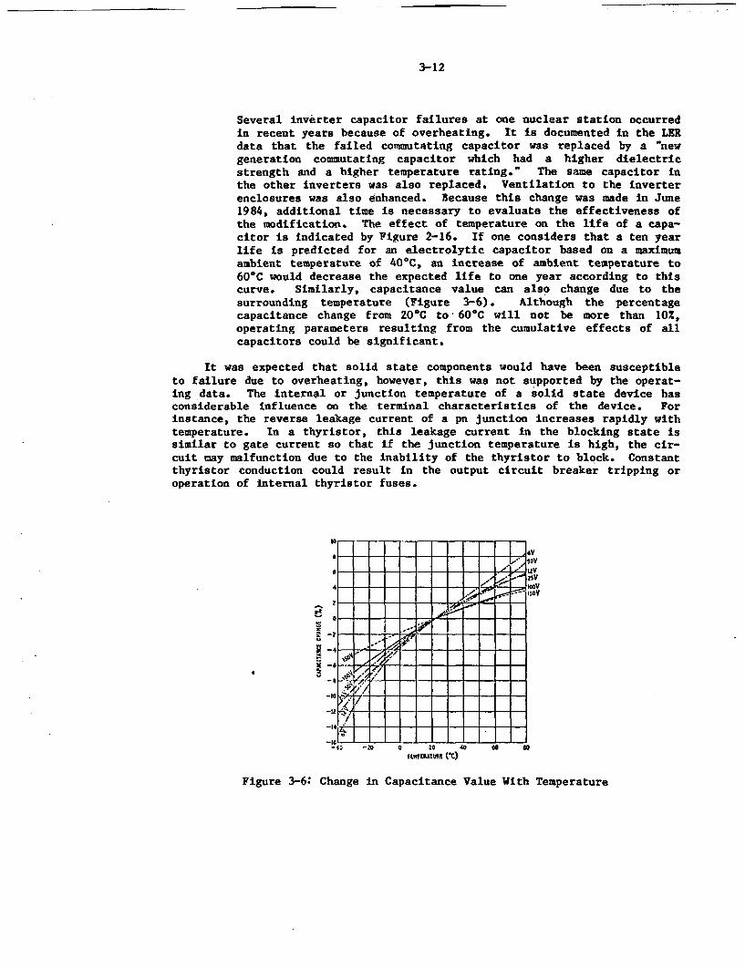
3-12
Several inverter capacitor failures at one nuclear station occurredin recent years because of overheating. It is documented in the LERdata that the failed commutating capacitor was replaced by a 'newgeneration commutating capacitor which had a higher dielectricstrength and a higher temperature rating.' The same capacitor inthe other inverters was also replaced. Ventilation to the inverterenclosures was also enhanced. Because this change was made in June1984, additional time is necessary to evaluate the effectiveness ofthe modification. The effect of temperature on the life of a capa-citor is indicated by Figure 2-16. If one considers that a ten yearlife is predicted for an electrolytic capacitor based on a maximumambient temperature of 40'C, an increase of ambient temperature to60'C would decrease the expected life to one year according to thiscurve. Similarly, capacitance value can also change due to thesurrounding temperature (Figure 3-6). Although the percentagecapacitance change from 20C to 60'C will not be more than 102,operating parameters resulting from the cumulative effects of allcapacitors could be significant.
It was expected that solid state components would have been susceptibleto failure due to overheating, however, this was not supported by the operat-ing data. The internal or junction temperature of a solid state device hasconsiderable influence on the terminal characteristics of the device. Forinstance, the reverse leakage current of a pan junction increases rapidly withtemperature. In a thyristor, this leakage current in the blocking state issimilar to gate current so that if the junction temperature is high, the cir-cuit may malfunction due to the inability of the thyristor to block. Constantthyristor conduction could result in the output circuit breaker tripping oroperation of internal thyristor fuses.
a-
3
7 _ - _ _ -_ __ _soy
-4 0 -a o 20 40 -f -
UiwMAUE (t)
Figure 3-6: Change in Capacitance Value With Temperature
3-13
3.3 Testing Induced Stresses
Technical specifications require that capacity testing be performed onthe station battery and its associated battery charger at a regular interval(typically every refueling outage for the charger). The capacity test is in-tended to simulate the loads calculated to exist under an accident conditionwhere the charger must carry the dc loads while recharging the depleted bat-tery within a specified time. These dc loads consist of pumps, MOVs, instru-mentation, and controls. This same criteria is used for sizing the chargerand can be shown as follows:
Ac' [[(AH)(K)/TI + LI K1K2 - AK1K2.
A - Required charger output (amps).Ac Corrected charger size for temperature and altitude (amps).
A- "Capacity removed from the battery in ampere hours.
T - Time required to recharge the battery to 95% capacity (hours).L - Continuous load on dc system during recharging (amps).K - Charger conversion factor based on battery type (Lead Acid Cells,
K - 1.1, Nickel-Cadmium Cells, X - 1.4).K1- 1.20 for temperatures between 40'C and 50'C, 1.56 for temperatures
between 50'C and 60'C.K2- 1.06 for altitude between 3300 and 5000 feet.
At least a 20X design margin should also be included in the sizing calcu-lation to allow for load growth on the dc system. The addition and/or modifi-cation of nuclear plant systems has resulted, in an increase in battery chargerdemands sometimes even requiring the installation of new chargers and bat-teries.
To verify that the charger is capable of meeting Its design loading,large resistor banks and sophisticated control equipment are used to simulatethe accident loading conditions. Kisoperation of this equipment may have con-tributed to some of the test failures reported, although, the number offailures (13) occurring during testing, especially in the case of batterychargers, remains significant. As illustrated in Figure 3-7, capacity testingresulted in a large number of circuit board failures, consisting of firingmodules and control modules. It is believed that if the testing had not beenperformed, normal operation at lower loads could have continued. Therefore,the testing was useful in detecting weak links. Several examples are indi-cated where capacity testing provided information important to the charger'sability to perform its safety function:
* When the output was increased on a magnetic amplifier type chargerto meet the capacity test requirements, arcing was observed across abad electrical wiring connection.
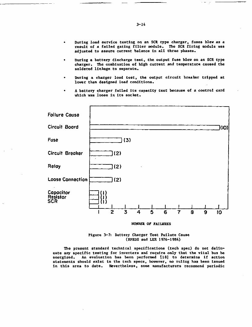
3-14
During load service testing on an SCR type charger, fuses blew as aresult of a failed gating filter module. The SCR firing module wasadjusted to assure current balance in all three phases.
* During acharger.soldered
battery discharge test, the output fuse blew on an SCR typeThe combination of high current and temperature caused thelinkage to separate.
During a charger load test, the output circuit breaker tripped atlower than designed load conditions.
A battery charger failed its capacity test because of a control cardwhich was loose in its socket.
Failure Cause
Circuit Board
Fuse
Circuit Breaker
Relay
1(10)
1(3)
(2)
1(2)
(2)
I )
112)
I I I I I I I I I I
Loose Connection
CapacitorResistorSCR
I 2 3 4 5 6 7 8 9 10
NUMBER OF FAILURES
Figure 3-7: Battery Charger Test Failure Cause(NPRDS and LER 1976-1984)
The present standard technical specifications (tech spec) do not delin-eate any specific testing for inverters and require only that the vital bus beenergized. An evaluation has been performed 118] to determine if actionstatements should exist in the tech specs, however, no ruling has been issuedin this area to date. Nevertheless, some manufacturers recommend periodic
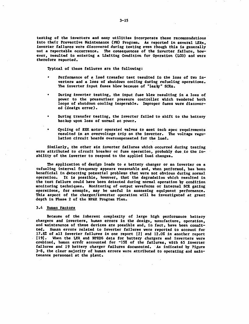
3-15
testing of the inverters and many utilities incorporate these recommendationsinto their Preventive Maintenance (PM) Program. As reported in several LERs,Inverter failures were discovered during testing even though this is generallynot a reportable occurrence. The consequences of the inverter failure, how-ever, resulted in entering a Limiting Condition for Operation (LCO) and weretherefore reported.
Typical of these failures are the following:
* Performance of a load transfer test resulted In the loss of two In-verters and a loss of shutdown cooling during refueling operations.The inverter Input fuses blew because of 'leaky' SCRs.
* During Inverter testing, the input fuse blew resulting in a loss ofpower to the pressurizer pressure controller which rendered bothloops of shutdown cooling inoperable. Improper fuses were discover-ed (design error).
* During transfer testing, the inverter failed to shift to the batterybackup upon loss of normal ac power.
* Cycling of RHR motor operated valves to meet tech spec requirementsresulted in an overvoltage trip on the Inverter. The voltage regu-lation circuit boards overcompensated for the load.
Similarly, the other six inverter failures which occurred during testingwere attributed to circuit breaker or fuse operation, probably due to the In-ability of the inverter to respond to the applied load changes.
The Application of design loads to a battery charger or an inverter on arefueling interval frequency appears reasonable and, when performed, has beenbeneficial in detecting potential problems that were not obvious during normaloperation. It is possible, however, that the degradation which resulted inthe test failure could have been detected during normal operation by conditionmonitoring techniques. Monitoring of output waveforms or Internal SCR gatingoperations, for example, may be useful in assessing equipment performance.This aspect of the charger/inverter operation will be investigated at greatdepth in Phase 2 of the SPAR Program Plan.
3.4 Human Factors
Because of the inherent complexity of large high performance batterychargers and inverters, human errors in the design, manufacture, operation,and maintenance of these devices are possible and, in fact, have been commit-ted. Human errors related to inverter failures were reported to account for17.8% of all Inverter failures in one report 121 and 12.0 in another report1191. When the LER and NPRDS data for battery chargers and inverters werecombined, human errdr accounted for -15% of the failures, with 65 inverterfailures and 19 battery charger failures documented. As indicated by Figure3-8, the clear majority of human errors were attributed to operating and main-tenance personnel at the plant.
3-16
Moint /Testing (36)
Operations I(26)
Design I(15)
Incidental (6)
Fabrication (1)I I I I I I I I I I I I
0 3 6 9 12 1 5 18 21 24 27 30 33 36Number of Events
Figure 3-8: Personnel Errors - Battery Chargers and Inverters
Maintenance and testing errors include incorrect calibration of circuitbreaker trip settings, short circuits caused by test equipment wiring, andimproper adjustment of float/equalize potentiometers. Operation errors weregenerally of a less technical nature such as the mistaken opening of input oroutput circuit breakers, neglect or improper response to equipment troublealarms, and incorrect 'lining up" of the equipment (dc supply not connected toenergized inverter). Design errors deal with capacitor rating, fuse sizing,and transformer insulation along with an incorrect set point for a chargerhigh voltage trip. Several inverter and charger failures were attributed topersonnel errors external to the charger/inverter boundary including acciden-tal bumping of a circuit breaker and a short circuit on the supplied equipmentdue to personnel contacting energized equipment. These failures are classi-fied as incidental. The one fabrication error in the data base is interestingin that the licensee reported "a gradual decay of float voltage level" due todefective zener diodes. Zener diodes are used in the voltage regulation cir-cuitry of inverters and chargers, and could exhibit changing characteristicswith time (aging) due to certain undersireable impurities introduced duringthe manufacturing process.
The consequences of personnel errors were significant as noted below:
• Four reactor trips resulted from personnel errors associated withinverters.
• A battery charger output circuit breaker opened causing an alarm,however, no operator response was made. The battery discharged,rendering HPCI inoperable. An attempt to use HPCI on a subsequentplant transient failed because of the low dc voltage condition.
* An inverter was energized from an ac supply with the dc supplybreaker inadvertently left open. Loss of ac power would havede-energized the vital bus.
3-17
3.5 Synergistic Effects
As Indicated in Appendix A of IEEE 650-1979 (6], stress on resistors,capacitors, and semiconductors may be calculated on the basis of the appliedvalue of certain parameters, such as current and voltage, as compared to theirrated values. Worst case operating mode conditions when applied singularlyprovide a conservative analysis since In actuality, worst case conditions can-not occur for all components simultaneously. When considering silicon basesemiconductors, however, Appendix B of IEEE 650-1979 states that these compo-nents 'never wear out if constructed and used according to specifications."As the failure data base indicates, events such as electrical transients orpersonnel error can exceed specifications and lead to accelerated aging ofeven these stable components.
Humidity by itself is not considered an aging mechanism for inverters andchargers located in a mild environment. However, when coupled with insulationor connector degradation, the moisture could provide an electricalpath between the component and ground. Loose connections, cited as an impor-tant failure mode In chargers and inverters, allow moisture to enter the con-tact surface which could increase the corrosion rate on contact surfaces.
Similarly, circuit breakers, relays, and switches will age because of thewear out nature of cycling these devices. A review of recent equipment quali-fication tests demonstrates that a large amount of conservatism is built intothe design of these devices, since in practice, monthly cycling is the maximumconceivable cycling anticipated, yet the design allows for hourly cycling.
As indicated earlier in this report, electrolytic capacitor life is pro-portional to temperature, voltage, and ripple current. The combined effectsof these parameters on capacitors is difficult to assess but is generally con-sidered to be additive.
3.6 Aging - Seismic Correlation
The correlation of seismic effects on aged battery chargers and invertersis difficult to establish quantitatively because of the complexities asso-ciated with the age related degradation of the many subcomponents used in thisequipment. However, by making certain reasonable assumptions, including theconsideration that battery chargers and inverters are identical in construc-tion and subcomponent composition, qualitative analysis of seismic effects onbattery chargers and inverter operation can be performed.
The present state of the art In this area includes three different ap-proaches that can be used to establish the aging-seismic correlation for anyequipment. Two of the methods relate to assessing equipment which has beensubjected to laboratory seismic tests or to actual seismic events. The fra-gility of nuclear power plant equipment is also being studied and may provideimportant input in this area [381. The third approach is an analytical methodsuggested by Sugarman [20] which requires identification of equipment "weaklinks," and a determination of how these weak links will act when subjected to
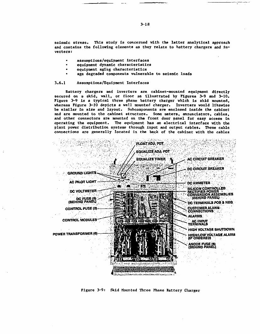
3-18
seismic stress. This study is concerned with the latter analytical approachand contains the following elements as they relate to battery chargers and in-verters:
* assumptions/equipment interfaces* equipment dynamic characteristics* equipment aging characteristics* age degraded components vulnerable to seismic loads
3.6.1 Assumptions/Equipment Interfaces
Battery chargers and inverters are cabinet-mounted equipment directlysecured on a skid, wall, or floor as illustrated by Figures 3-9 and 3-10.Figure 3-9 is a typical three phase battery charger which is skid mounted,whereas Figure 3-10 depicts a wall mounted charger. Inverters would likewisebe similar in size and layout. Subcomponents are enclosed inside the cabinetand are mounted to the cabinet structure. Some meters, annunciators, cables,and other connectors are mounted on the front door panel for easy access inoperating the equipment. The equipment has an electrical interface with theplant power distribution systems through input and output cables. These cableconnections are generally located in the back of the cabinet with the cables
EQAU!TIM R A ICI RAE
-w DC CIRCUTBRKE- GROUN LUGHTS -i -
AC PILOT LIGHT___________DAM TR
,DC VOLTMETER RECTIFIER POWER
- ----- P~-~"CONVERSION ASSEMIBLIES,- (BEHIND PANEI4
BDC N-.RMINALS P. ., NE
CONTROL FUSE:(S)- CUSTOMER ALARM.CONN5CTINS.
CONTROL MODULES A NU
'HIGH VOLTAGE SHUTDOWNPOWER TRANSFORMER (S) HIGHLW OTGE ALARM
(IF ORDERED),
(BEINDPANM
Figure 3-9: Skid Mounted Three Phase Battery Charger
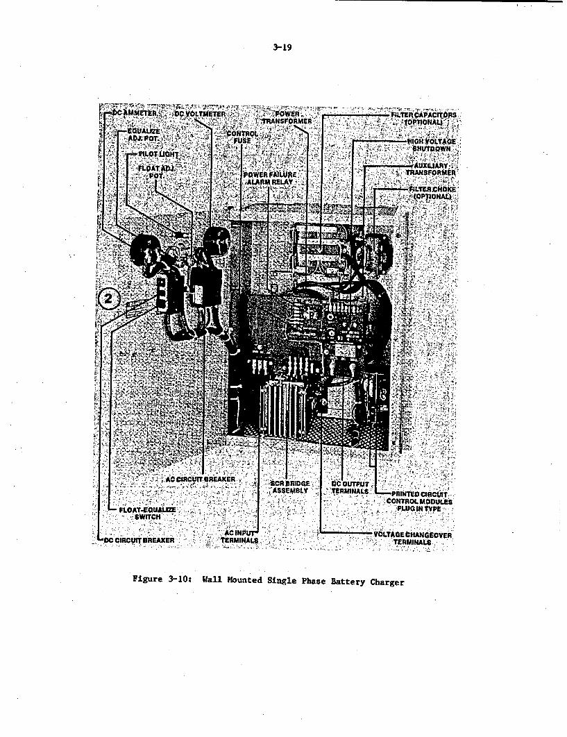
-3-19
C CIRCUIT REAKERI R BRIDGE
_ c CIRCUIT BREAKER TRMINA:.
i TEFRM1NALS-.,. PRINTE CRCITi
;V, T GEeHANGEiOVEn* -- 0 a;-TERMINALS0
Figure 3-10: Wall Mounted Single Phase Battery Charger
3-20
passing through the cabinet at the bottom or the side. It is important thatthe cable be sufficiently flexible in the connection area to allow for vibra-tion displacement. A second interface of this equipment is the structuralconnection with the floor, wall or skid. The manner in which the charger orinverter is mounted is considered part of this evaluation, whereas the sup-porting structure construction (floor, wall, etc.) is not. Failure of eitherthe electrical interface due to cable disconnection or of the structural in-terface due to failure of the structure itself would result in equipmentfailure.
In addition to the above two interfaces, falling objects dislodged fromnearby structures or equipment, or debris on or around, the equipment couldresult in equipment malfunction. All of these conditions are assumed out ofscope in this analysis. Proper protective barriers should be built to isolatethe equipment from any water/steam/chemical spray, missiles, or broken liveelectrical connectors. On the basis of the above, the boundary of the equip-ment is thus defined as the battery charger or inverter cabinet along with thesubcomponents within the cabinet and the mounting of the cabinet to a support-ing structure.
Most of the battery chargers and inverters used in nuclear power plantswere manufactured by six primary vendors. Although there exist several dif-ferent designs, the physical appearance and construction of the units includ-ing the mounting of subcomponents inside the cabinet are similar. The size ofan inverter is designated by its voltage-ampere rating. The weight of an in-verter varies from as little as 30 lb for a 0.5KVA rated unit to 4000 lb for a200 IVA unit. Similarly, battery chargers have weights ranging from 60 to5000 lbs. The physical size of the equipment also varies significantly. Anaverage sized charger/inverter weighing about 1000 to 1500 lbs is consideredfor this analysis.
Although aged components vulnerable to dynamic loads will be identifiedin this section, it is imperative to note that the equipment along with allthe subcomponents attached to the cabinets are mounted as specified in theoriginal qualification report and are maintained that way throughout the lifeof the equipment. Random failures caused by loose screws, inadvertent trippingof a switch, and improper maintenance practices are not part of this evalua-tion. It is further assumed that manufacturer's recommended component re-placements such as electrolytic capacitors are performed during the life ofthe equipment.
Considering the above assumptions, an attempt is made to discuss as wellas identify the problem sources and root causes that could result in agedbattery charger or inverter failure at the time of maximum system demand.
3.6.2 Dynamic Characteristics
Equipment construction and subcomponent layout information is required todefine its overall dynamic characteristics. The inertial load generated bythe equipment mass as a result of self induced or externally induced vibratoryexcitations are obtained on the basis of the mass distributions of the equip-ment. In the case of a battery charger or inverter, the major weight contri-bution is the steel cabinet structure which amounts to almost 70% of the total
3-21
weight of the equipment. The remaining 301 of the total weight is from themany electrical elements. The power transformers, which constitute one-thirdof this weight, are located in the bottom portion of the equipment. Thus,dividing the entire panel into three compartments, the total weight distribu-tion from bottom to top is 45%, 301, and 25%, respectively. Vital componentssuch as relays, circuit breakers, SCRs, and PC-boards are located in the cen-tral compartment. The top compartment holds some capacitors, lights, meters,and switches. In addition to these compartments, some control boards may bemounted on the front door panel which is made of a thicker steel plate thanthe remaining cabinet sides.
With regard to the structural strength (i.e., stiffness) of the equip-ment, the frame of the equipment is generally one piece consisting of the fourcorner legs and the cross beams connecting them at the top and bottom, andsometimes at intervals between depending on the total height of the-equipment.Except for the front plate, the sides are braced and covered with thin sheetmetal. The front plate, particularly the door, is generally made of thickerplate and adds strength to the overall structure. Several subframes are builtinside the cabinet from the parent frame structure to support the electricalcomponents. It should be noted that the electrical components by themselvesadd no strength to the equipment. Based on this design, the equipment can beconsidered to be flexible either in flexural (side-side/front-back) or tor-sional (about vertical axis modes only) motion. Additionally, the structurewould exhibit rigid body motion in any of the translational directions alongwith the entire building structure housing the component.
Another factor that would affect the equipment structural ability is themounting condition. Most larger units are skid mounted on the floor of abuilding. They are either bolted or fillet welded (4 inch welds are typical)with uniform spacing between welds, with the floor rails anchored to the floorconcrete. In addition to the type of anchoring, rows of cabinets are ofteninstalled side by side and/or back to back, connected to each other with adamped material (spacer) between them. Unlike a single cabinet case, thisarrangement sometimes eliminates the flexural and torsional deformation of theequipment by stiffening the overall structure. Many smaller sized units usedin the fire protection system, or some other specific system applications, arewall mounted. In this case, as well as in an array of cabinets installedtogether, the equipment primarily experiences rigid body motion under dynamicloads.
Mounting of individual electrical components within the cabinet frame isconsidered separately. Each of these components, such as capacitors, break-ers, relays, transformers, etc. is an individual equipment item by itself.However, with respect to the charger/inverter assembly it Is sufficient toassume that these components exhibit only rigid body motion except for suchspring loaded elements as relays and breakers. Proper maintenance programsshould be instituted to keep these components securely attached to the frame.
As with mounting considerations, the sizes of the overall equipment cabi-net as well as the individual components could affect the dynamic characteris-tic of the equipment. Taller units are more susceptible to dynamic failurethan the shorter ones. For the equipment under consideration, most units are
3-22
not under the former category and hence, the size of this equipment has littleeffect on the overall dynamic behavior. However, each individual component,such as a printed circuit board, is screwed to the cabinet at different pointson the supporting frame raised from the cabinet. In this case, care must betaken to ensure that no relative motion between these supporting points can bepossible under a dynamic condition.
Materials used in the construction are another factor which influencesthe dynamic behavior. The cabinet material is steel which provides strengthto the equipment and helps to withstand any dynamic load. Many individualcomponents are made of nonmetallic materials such as polymers. Some of thesepolymers are brittle or could become brittle with age, and are sensitive toany sort of bending forces acting on them.
Taking all the above factors into account, a simple calculation has indi-cated that the subject equipment has a flexural and torsional natural fre-quency well above the seismic range of 33 Hz. However, a manufacturer's seis-mic test of a battery charger has revealed that one of the horizontal fre-quencies is on the order of 16 Hz which is within the seismic strong motionrange. It is not clear from the test whether this frequency is correspondingto the bending mode or any of the side panel vibration (localized plate vibra-tion) where the accelerometer may have been attached. Although the dynamic'characteristic of every individual design is different, it is reasonable toassume that the overall dynamic behavior of a typical battery charger or in-verter will be the rigid body motion of the'equipment. The bending or tor-sional effects on the equipment components will be minimal. This conclusionis subjected to the following conditions:
* The doors and wall panels are maintained rigidly attached to thecabinet frame.
* Mountings of the cabinet as well as the individual components arerigid.
All electrical boards (PC or control) experience no relative motionfrom the supporting structure.
3.6.3 Aging Characteristic
Battery chargers and inverters, as mentioned earlier, consist of a metalcabinet which houses many electrical components. This equipment, designed toprovide power to equipment vital to plant safety, is primarily located in thecontrol building. The control building maintains a controlled environment be-cause of the electronic components vulnerable to a hostile environment such ashigh humidity, high temperature and high radiation. Therefore, the subjectequipment can be assumed to experience a mild environment during its lifetime.
Based on the above assumption as well as the operating experience studyperformed, the environmental parameters include dust/dirt, temperature andhumidity. In addition to this, the equipment itself generates heat whichmight raise the cabinet temperature to cause thermal and thermal fatigue typesof damage. It should be noted that the bottom cabinet section Is often
3-23
louvered to dissipate the heat from components located In that area,especially the transformers. Other age-related degradation include wear ofcertain components, and carbon deposits due to arcing on components withcontacts. Humming noise generated due to cyclic forces within thetransformers or any high voltage components also induce high frequencyvibration inside the cabinet. For a forty year design life, the equipment hasthe normal service condition defined as:
Ambient Temperature: 850FRelative Humidity: 20-90%Total Integrated radiation: 1E3 tad gamma
Radiation levels in the control building are very low. Several radiationstudies indicate that the lowest radiation damage threshold applicable to theequipment components exceeds the specified radiation requirement by an orderof magnitude. Therefore, radiation exposure is not a concern.
Temperature of the cabinet environment is augmented by the heat dissi-pated from the transformers and other devices. Since in the vicinity of thesedevices the temperature may be well above the value mentioned above, tempera-ture sensitive components such as fuses and capacitors, should be mounted awayfrom these heat sources. The cooling fan, if forced air cooling is used,should be properly maintained to remove as much heat as possible during thelife of the equipment. Relative humidity of the control building should bekept low to avoid any shorts in the control boards or corrosion of metal com-ponents. For plants located in high humidity regions, additional precautionsshould be taken to maintain a lower humidity inside the control building. Theexistence of carbon deposits on the contact points of relays and breakers, ordust or dirt buildup in the cabinet should be checked periodically. Trans-former insulating systems can also degrade when the high temperature is accom-panied by a humid atmosphere as well.
On the basis of the above, Tables 3-1 and 3-2 identify the componentsthat are not critical for equipment performance and those that are very criti-cal for proper equipment operation. In addition, Table 3-2 identifies compo-nents sensitive to aging which should be included in a maintenance program tomaintain their design function. Another form of aging caused by mechanicalloads such as noise and internally induced vibration affect the soldering andcompression types of connections of PC boards, capacitor leads, and contactsof relays and circuit breakers.
Corrosion of mounting bolts and cracking of mounting welds for the cabi-net are another form of age-related failures. Loose mounting bolts, both forcabinet mountings and other electrical components inside the cabinet, andloosening of fasteners holding certain devices could cause serious problemsunder vibratory loads.
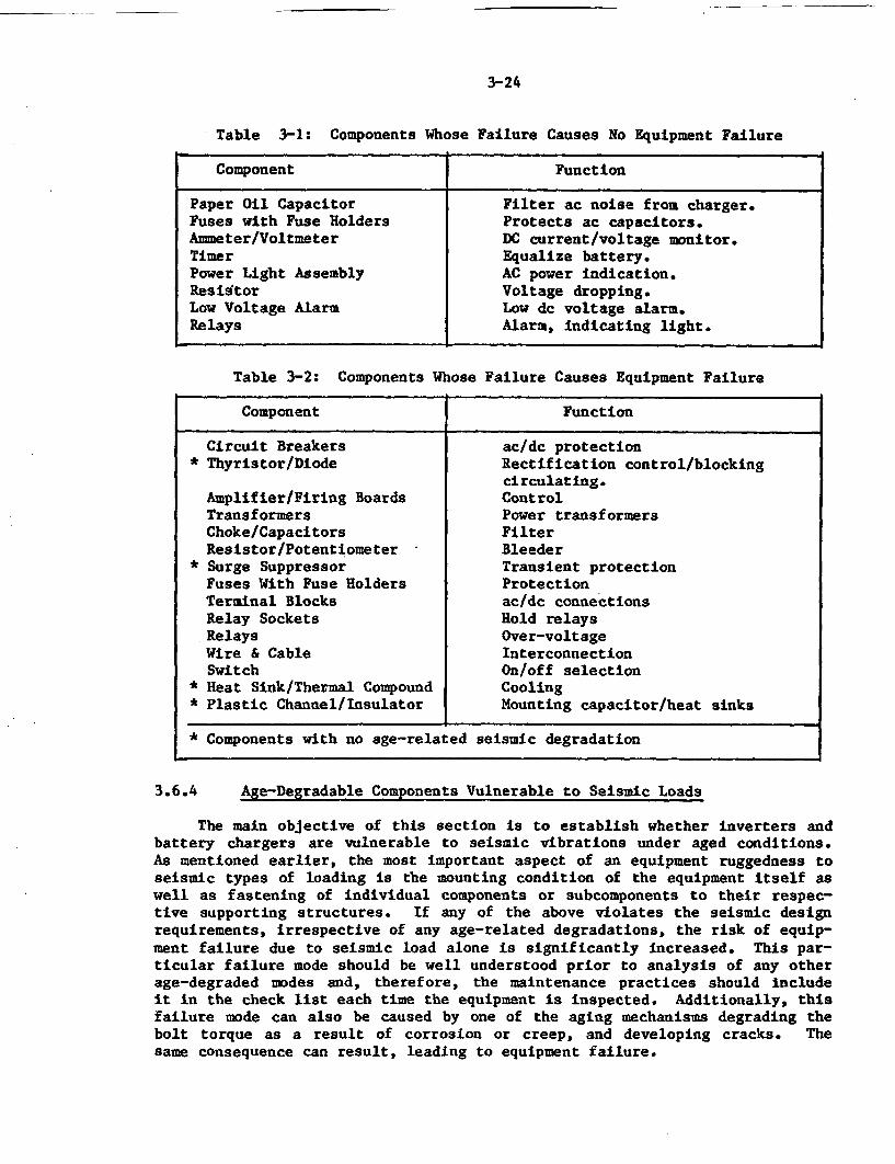
-- -
3-24
-Table 3-1: Components Whose Failure Causes No Equipment Failure
Component Function
Paper Oil Capacitor Filter ac noise from charger.Fuses with Fuse Holders Protects ac capacitors.Ammeter/Voltmeter DC current/voltage monitor.Timer Equalize battery.Power Light Assembly AC power indication.Resistor Voltage dropping.Low Voltage Alarm Low dc voltage alarm.Relays Alarm, indicating light.
Table 3-2: Components Whose Failure Causes Equipment Failure
Component Function
Circuit Breakers ac/dc protection* Thyristor/Diode Rectification control/blocking
circulating.Amplifier/Firing Boards ControlTransformers Power transformersChoke/Capacitors FilterResistor/Potentiometer Bleeder
* Surge Suppressor Transient protectionFuses With Fuse Holders ProtectionTerminal Blocks ac/dc connectionsRelay Sockets Hold relaysRelays Over-voltageWire & Cable InterconnectionSwitch On/off selection
* Heat Sink/Thermal Compound Cooling* Plastic Channel/Insulator Mounting capacitor/heat sinks
* Components with no age-related seismic degradation
3.6.4 Age-Degradable Components Vulnerable to Seismic Loads
The main objective of this section is to establish whether inverters andbattery chargers are vulnerable to seismic vibrations under aged conditions.As mentioned earlier, the most important aspect of an equipment ruggedness toseismic types of loading is the mounting condition of the equipment itself aswell as fastening of individual components or subcomponents to their respec-tive supporting structures. If any of the above violates the seismic designrequirements, irrespective of any age-related degradations, the risk of equip-ment failure due to seismic load alone is significantly increased. This par-ticular failure mode should be well understood prior to analysis of any otherage-degraded modes and, therefore, the maintenance practices should includeit in the check list each time the equipment is inspected. Additionally, thisfailure mode can also be caused by one of the aging mechanisms degrading thebolt torque as a result of corrosion or creep, and developing cracks. Thesame consequence can result, leading to equipment failure.
3-25
The laboratory controlled testing 1211 of this equipment revealed certainmodes of failures, including opening of relay contacts, blown fuses, extin-guished lamps, and shorted bulbs which further tripped relays. Some of thesemodes have resulted in declaring the particular equipment to be failed. Aftertightening their mountings and replacing several with new units, these fail-ures were avoided for the remainder of the test. Note that some of thesefailures are attributed to blown fuses or relay trips, which are designed tooperate under abnormal conditions. Other studies based on the real earthquakeexperience data 1221 have indicated that in nonnuclear facilities, cabinettype components not mounted to the floor have displaced from their originallocation with effect on the equipment function. Protective relays are alsonoted to trip under the real earthquake loads.
Certain components such as relays and circuit breakers are inherentlyprone to trip or chatter under dynamic loads. It has not been establishedwhether this behavior will worsen as these components age. Since some of therelays used for this equipment are of the protective type, relay chatter orrelay movement in its socket could trip the circuit breaker and cause theequipment to fail. Thus, tripping of circuit breakers is one of the modeswhich could be expected during a seismic event.
Cracking of PC boards, terminal blocks, and other nonmetallic brittlecomponents, or embrittlement or warping/twisting of components with age (i.e.,heat) are possible modes of failure under seismic conditions. The design andmounting of these components should be such that no relative displacement isexperienced at its opposite ends while vibrating. Caution should be taken notto mount components of this type to the sheet metal sides used to form theenclosure. Localized plate vibration of these walls could induce twisting andbending forces. It is a good practice to build a subframe from the cabinetmain frame to support all these components. If any latching devices are used,such as in the case of the door lock, caution should be taken that they remainsecurely fastened. Some noncritical items are attached to the doors and couldbecome dislodged or broken and affect the equipment Integrity. Interconnect-Ing cables between different electrical devices should be sufficiently flex-ible to be able to dampen some of the vibratory input rather than snapping outof their connecting ends. It is prudent to tie these cables/wires to the cab-inet walls intermittently to avoid any bouncing or colliding effect on adja-cent components.
One Important age-degraded connection which could fail under dynamicmotion is the soldered connection of devices mounted on PC boards. Thesejoints degrade because of oxidation during the life of the charger or inver-ter. A small dynamic force could impose a sufficient load to detach the leadfrom the devices.
Transformers used in this equipment are primarily dry type. Their insu-lating systems degrade with age, which result in cracks or voids. This in-creases the leakage current and under dynamic loads, the growth of thesecracks or voids could accelerate which would render the component inoperable.Capacitors, on the other hand, are electrolytic or oil filled, and loss of oilor electrolyte makes the component incapable of holding a charge. Degradedcapacitors could leak after experiencing shocks or disconnect themselves fromthe system at their leads.
3-26
It has been established that this particular equipment would experiencerigid body motion under seismic excitation. Provided all components are at-tached to the main frame rigidly, they would also experience rigid body motionin any of the three global directions. Wyle tests 121J on such components in-dicated no aging-seismic related failures except for relays. However, thisparticular test does not simulate the real nuclear plant environment, specifi-cally the synergism of various environmental parameters, errors caused by im-proper maintenance, and other factors causing component failures and not welldefined by the researchers. It is true that components still do fail innuclear power plants for unknown reasons. Hence, preventive measures againstknown failures would generally improve the availability of the equipment,aswell as increase the plant availability and safety.
3.6.5 Conclusions
Few test or experience data are available to support the existence ornon-existence of an aging-seismic correlation for battery chargers and inver-ters. However, certain-components such as circuit breakers and relays are in-herently sensitive to failure (trip) under dynamic or vibratory excitation.Other components whibc degrade with age become vulnerable to cracks or discon-tinuity under seismic loads. These include fuses, capacitors, insulation ofmagnetics, resistors, and printed circuit boards where material embrittlement,for instance, can be an age related characteristic. In conclusion, batterychargers and inverters qualified to nuclear industry standards do not appearto exhibit any aging-seismic correlation provided the design characteristicsare maintained by implementing preventive maintenance as summarized below.
* Physical inspection of cabinet mountings to the floor, wall, orsupporting structures.
* Physical inspection of all components and subcomponents (inparticular printed circuit boards) mounted to the supporting framesinside the cabinet.
* Physical inspection of wires and cables connecting various vitalcomponents for their seismic fasteners as well as their end
- connections (i.e., weakening or degradation of connectors,soldering, terminal blocks, etc.)
Electrical tests (insulation resistance)/physical tests onage-sensitive components identified in Table 3-2 for possibleweakening effects detrimental to seismic loads.
* Physical inspection of relays/breakers for possible contact carbondeposits, or degraded coils, etc.
* Insulation tests on transformers for increased leakage currentthrough cracks or voids resulting from aging, which could failunder vibratory loads.
4-1
4.0 DATA EVALUATION AND ASSESSMENTS
Nuclear power plant battery charger and inverter operating experience in-formation was obtained from five different data sources, namely, LicenseeEvent Reports (LERs), In-Plant Reliability Data Systems (IPRDS), Nuclear PlantReliability Data Systems (NPRDS), Nuclear Power Experience (NPE) reports, andPlant Maintenance records. While some common data existed among thesesources, each offered certain unique information which made it desirable andnecessary to review all of them in detail. The cumulative information fromthese data sources offered insight into subcomponent failure modes, plantresponse to failures, equipment design information (capacity and type), andcorrective actions taken by the utility.
4.1 Licensee Event Report (LER) Review
LER abstracts were obtained from the computerized data file of theNuclear Safety Information Center (NSIC) maintained by Oak Ridge NationalLaboratory. The abstracts obtained were based on key words such as inverter,battery charger, battery, uninterruptible power, vital power, and direct cur-rent (dc) equipment. More than one thousand abstracts were reviewed for In-formation addressing charger and inverter failures occurring between January1976 and July 1984 and from this information approximately three hundred fail-ure events were selected for further analysis. The types of LERs excludedfrom the final data base were those addressing licensee test schedulingerrors, failures of batteries unrelated to charger performance, and LERsassociated with instrument power supplies which perform a specific functionnot relevant to either charger or inverter operation.
Valuable input to this time consuming review was provided by severalother studies, including two LER Data Summaries performed by Brown and Tro-jovsky [19, 231 and an analysis of inverter failures by Bozoki and Papazoglou[21. These reports categorized LERs and provided some insight into the database population and the type of information obtainable from LERs. Because ofthe specific goal of identifying and characterizing aging and service wear ef-fects, the summary information provided by these reports could not be used asa direct input to this study. Often, subjective judgements must be made re-garding the root cause failure or the plant impact of the failure since theLER is not sufficiently descriptive. It is important, therefore, that whenanalyzing data for aging/wear related trends that these judgements be madeconsistently by the same team of reviewers. In a number of instances, the en-tire LER with all attached correspondence was obtained from the NRC PublicDocument Room in order to ensure that accurate and complete information wasentered into the data base. In the few cases when this also proved to be in-sufficient, correspondence with the licensee or NRC resident inspectors pro-vided the information required. In order to analyze trends, combinations ofevents, and time-domain failure characteristics, the LER failure data forchargers and Inverters were placed into a BNL developed computerized data basesystem. Information such as failure modes, mechanisms, effects, and descrip-tion, manufacturer name, equipment rating, plant name, power level at whichthe failure occurred, and systems affected were entered into the data base byplant name and LER number. A subprogram which simply calculates the plant ageat the time of failure by comparing the date of first criticality to the date
-
4-2
of the failure event, provided age related information which was used forvarious sorts. Note that in calculating the age of the equipment it wasassumed that the equipment was not replaced subsequent to plant criticality.This was necessary since the equipment history for each plant was not avail-able for determining the exact equipment age. These sorts were analyzed andpertinent ones are displayed in graphical form in this report.
Because of the extensive work accomplished in the LER data area, Brownand Trojovsky were contacted to discuss a small number of differences betweentheir data summaries and the BNL LER listing developed from the NSIC input.These variations were resolved which resulted in an accurate and complete database from which the analysis was conducted.
LERs made up the largest single source of data on inverter and batterycharger failures. Although possessing certain limitations, this data bank didprovide relevant information on failure mechanisms, modes, and effects. Thefollowing qualifications are noted in order to place the conclusions derivedfrom these data In the proper perspective.
Because 16 plants, including 15 BWRs, do not classify their vital bus in-verters as safety related, inverter failures at these sites would not bereported via an LER. It should be noted that inverter failures at theseplants could affect safety system operation or at least result in challengesto these systems. This observation is based on a review of FSAR informationfor several of the plants.
A second qualification is that a number of older plants have no technicalspecification requirements for inverters and/or battery chargers even thoughthis equipment is considered safety-related. For instance, one plant whichhas a battery charger for each of its two batteries along with one charger instandby has only one tech spec requirement for chargers, and that is to havetwo of the three available before taking the reactor critical. A chargerfailure during operation does not violate tech specs and therefore would notrequire an LER. Additional evidence that no tech specs for safety related in-verters exists at older plants was obtained by direct contact with three olderfacilities. Plant personnel verified that inverter failures had occurred(several even resulting in reactor trips), although no inverter related LERshad been issued by any of these units.
Additionally, units with two connected full capacity battery chargers perbattery are not in violation of tech specs upon failure of one charger andwould therefore not initiate an LER for that event Therefore, single batterycharger failures at these plants would not be documented by an LER.
From the above, it is estimated that LER data would be representative ofinverter failures at approximately 50 of the 80 plants in operation during theperiod reviewed, and of battery charger failures at 60 of the 80 plants.Bearing in mind the above qualifications, a sufficiently large data baseexisted to conduct an analysis which resulted in the observations andconclusions summarized in the following paragraphs.
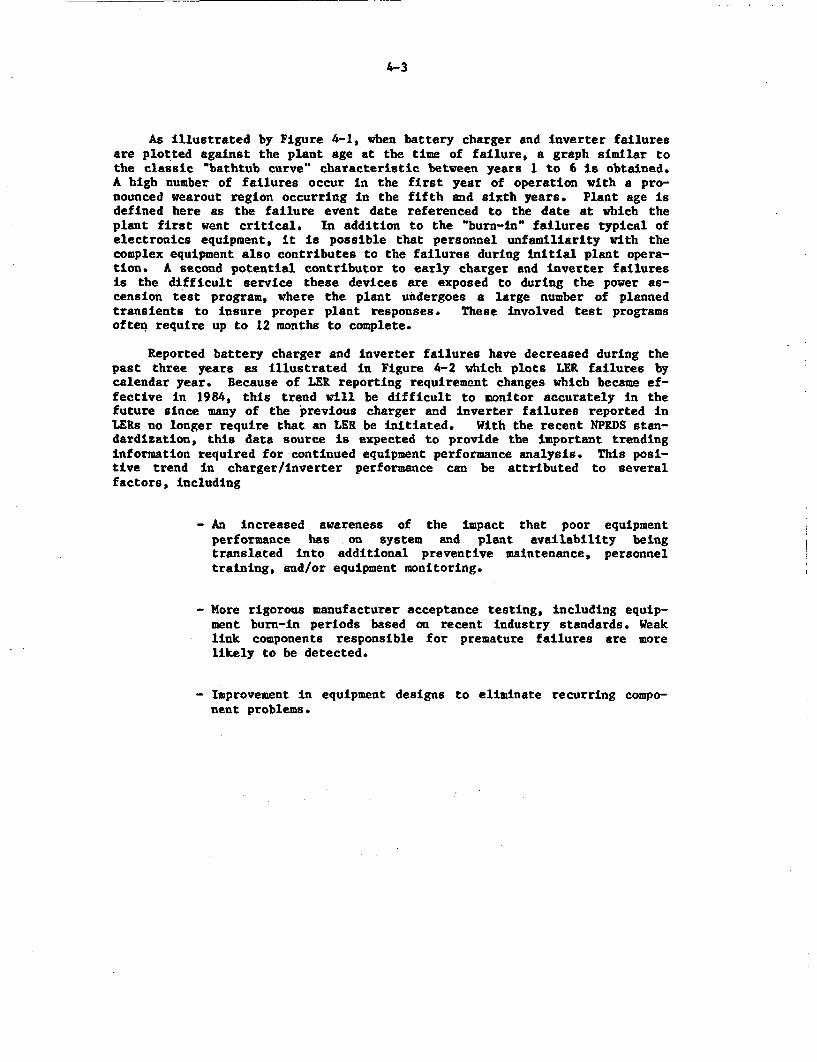
4-3
As illustrated by Figure 4-1, when battery charger and inverter failuresare plotted against the plant age at the time of failure, a graph similar tothe classic "bathtub curve" characteristic between years 1 to 6 is obtained.A high number of failures occur in the first year of operation with a pro-nounced wearout region occurring in the fifth and sixth years. Plant age isdefined here as the failure event date referenced to the date at which theplant first went critical. In addition to the 'burn-in' failures typical ofelectronics equipment, it is possible that personnel unfamiliarity with thecomplex equipment also contributes to the failures during initial plant opera-tion. A second potential contributor to early charger and inverter failuresis the difficult service these devices are exposed to during the power as-cension test program, where the plant undergoes a large number of plannedtransients to insure proper plant responses. These involved test programsoften require up to 12 months to complete.
Reported battery charger and inverter failures have decreased during thepast three years as illustrated in Figure 4-2 which plots LER failures bycalendar year. Because of LER reporting requirement changes which became ef-fective in 1984, this trend will be difficult to monitor accurately in thefuture since many of the previous charger and inverter failures reported inLERs no longer require that an LER be initiated. With the recent NPRDS stan-dardization, this data source is expected to provide the important trendinginformation required for continued equipment performance analysis. This posi-tive trend in charger/inverter performance can be attributed to severalfactors, including
- An increased awareness of the impact that poor equipmentperformance has on system and plant availability beingtranslated into additional preventive maintenance, personneltraining, and/or equipment monitoring.
- More rigorous manufacturer acceptance testing, including equip-ment burn-in periods based on recent industry standards. Weaklink components responsible for premature failures are morelikely to be detected.
- Improvement in equipment designs to eliminate recurring compo-nent problems.
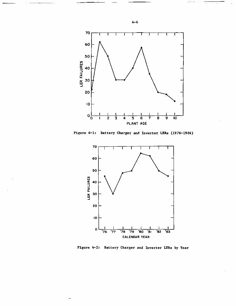
4-4
70
60 -
50U)
: 40
-I
c 30
-J
20 -
10 -
0i
Figure 4-1:
PLANT AGE
Battery Charger and Inverter LERs (1976-1984)
70
60
50
U)
40
30
20 _
10
'76 '77 '78 '79 '80 'SI '82 '83
CALENDAR YEAR
Figure 4-2: Battery Charger and Inverter LERs by Year
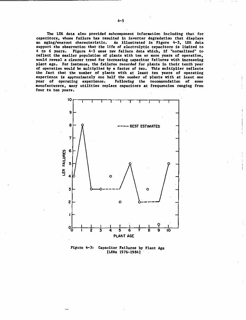
4-5
The LER data also provided subcomponent information including that forcapacitors, whose failure has resulted in inverter degradation that displaysan aging/wearout characteristic. As illustrated in Figure 4-3, LER datasupport the observation that the life of electrolytic capacitors is limited to4 to 6 years. Figure 4-3 uses raw failure data which, if "normalized' toreflect the smaller population of plants with ten or more years of operation,would reveal a clearer trend for increasing capacitor failures with increasingplant age. For instance, the failures recorded for plants in their tenth yearof operation would be multiplied by a factor of two. This multiplier reflectsthe fact that the number of plants with at least ten years of operatingexperience is approximately one half the number of plants with at least oneyear of operating experience. Following the recommendation of somemanufacturers, many utilities replace capacitors at frequencies ranging fromfour to ten years.
9
8 - BEST ESTIMATES
7
~1<LL
IAj A
PLANT AGE
Figure 4-3: Capacitor Failures by Plant Age[LERs 1976-1984|
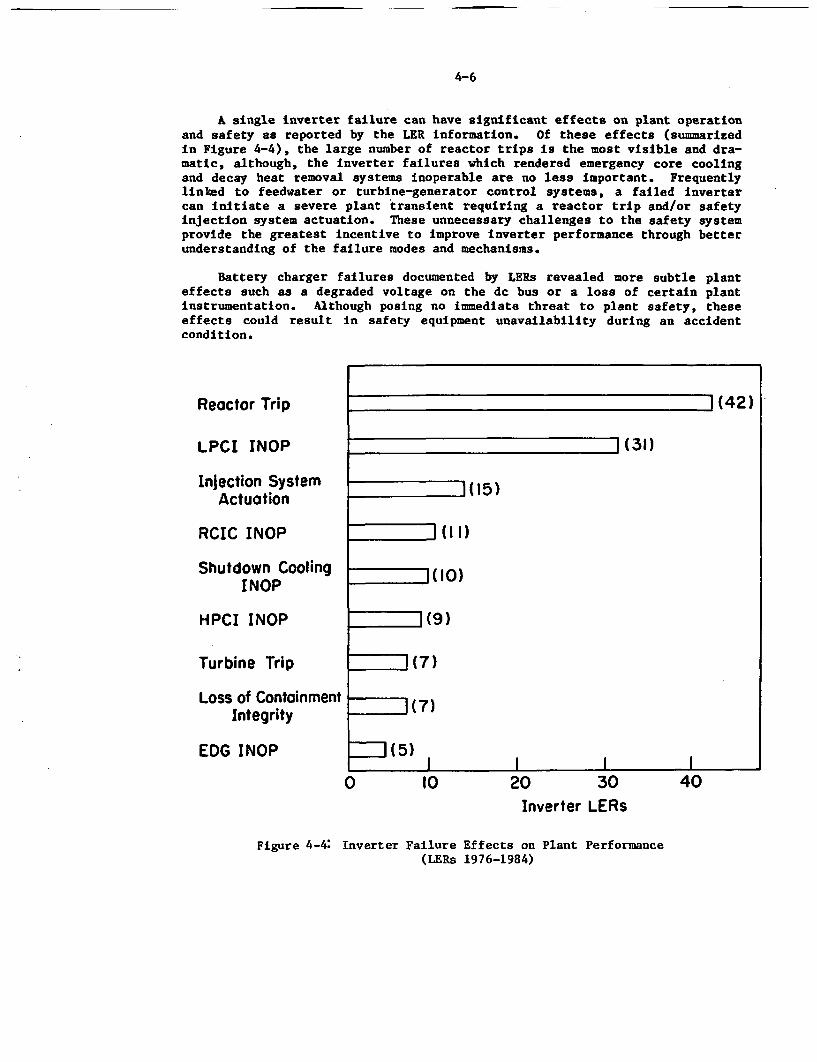
4-6
A single inverter failure can have significant effects on plant operationand safety as reported by the LER information. Of these effects (summarizedin Figure 4-4), the large number of reactor trips is the most visible and dra-matic, although, the inverter failures which rendered emergency core coolingand decay heat removal systems inoperable are no less important. Frequentlylinked to feedwater or turbine-generator control systems, a failed invertercan initiate a severe plant transient requiring a reactor trip and/or safetyinjection system actuation. These unnecessary challenges to the safety systemprovide the greatest incentive to Improve inverter performance through betterunderstanding of the failure modes and mechanisms.
Battery charger failures documented by LERs revealed more subtle planteffects such as a degraded voltage on the dc bus or a loss of certain plantinstrumentation. Although posing no immediate threat to plant safety, theseeffects could result in safety equipment unavailability during an accidentcondition.
Reactor Trip (42)
LPCI INOP (31)
Injection System " 15)Actuation
RCIC INOP I()
Shutdown Cooling (10)INOP
HPCI INOP I(9)
Turbine Trip 1(7)
Loss of Containment (7)Integrity
EDG INOP (5)_I I I I
0 10 20 30 40Inverter LERs
Figure 4-4: Inverter Failure Effects on Plant Performance(LERs 1976-1984)
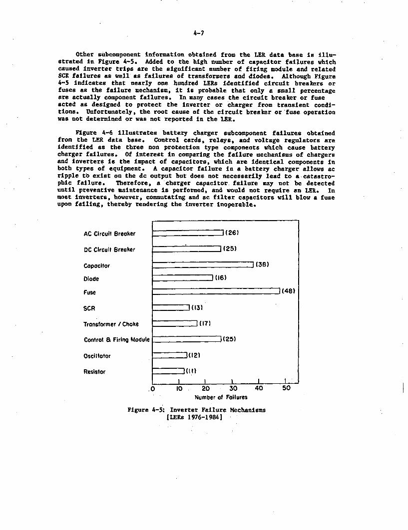
4-7
Other subcomponent information obtained from the LER data base is Illu-strated in Figure 4-5. Added to the high number of capacitor failures whichcaused inverter trips are the significant number of firing module and relatedSCR failures as well as failures of transformers and diodes. Although Figure4-5 indicates that nearly one hundred LERs Identified circuit breakers orfuses as the failure mechanism, it is probable that only a small percentageare actually component failures. In many cases the circuit breaker or fuseacted as designed to protect the inverter or charger from transient condl-tions. Unfortunately, the root cause of the circuit breaker or fuse operationwas not determined or was not reported in the LER.
Figure 4-6 illustrates battery charger subcomponent failures obtainedfrom the LER data base. Control cards, relays, and voltage regulators areidentified as the three non protection type components which cause batterycharger failures. Of interest in comparing the failure mechanisms of chargersand inverters Is the impact of capacitors, which are Identical components inboth types of equipment. A capacitor failure in a battery charger allows acripple tb exist on the dc output but does not necessarily lead to a catastro-phic failure. Therefore, a charger capacitor failure may not be detecteduntil preventive maintenance is performed, and would not require an LER. Inmost inverters, however, commutating and ac filter capacitors will blow a fuseupon failing, thereby rendering the inverter inoperable.
AC Circuit Breaker
DC Circuit Breaker
Capacitor
Diode
Fuse
SCR
Transformer / Choke
Control a Firing Module
Oscil otor
Resistor
(26)
77I (25)
I(38)
(16)
1(48)
I (13)
l(17)
(25)
I(12)
(I 1)
.0
Figure 4-5:
10 20 30Number of Failures
40 50
Inverter Failure MechanismsILERs 1976-1984|
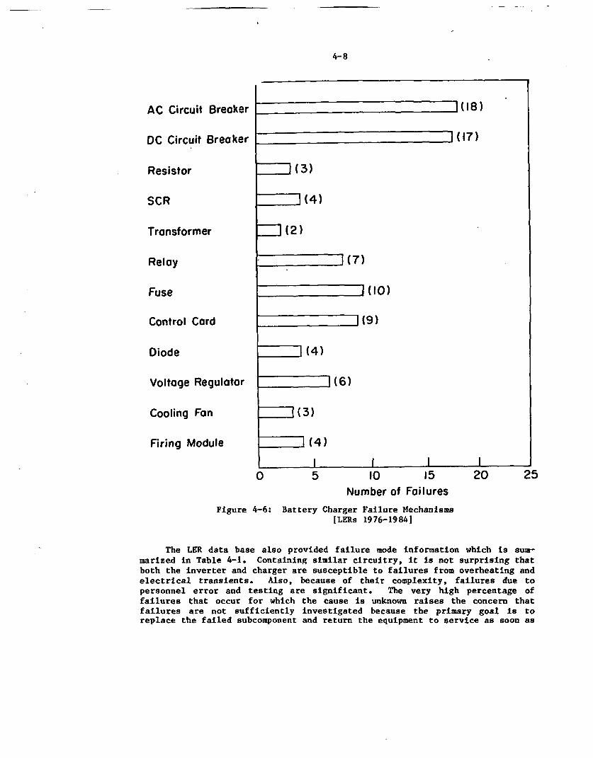
4-8
AC Circuit Breaker
DC Circuit Breaker
Resistor
SCR
Transformer
Relay
Fuse
Control Card
Diode
Voltage Regulator
Cooling Fan
Firing Module
-I (18)
](17)
1(3)
(4)
= (2)
](7)
= (10)
7171(9)
-zhI (4)
1 (6)
1(4)
l l I I0 5 10
Number of15
Failures20 25
Figure 4-6: Battery Charger Failure Mechanisms[LERs 1976-1984]
The LER data base also provided failure mode information which is sur-marized in Table 4-1. Containing similar circuitry, it is not surprising thatboth the inverter and charger are susceptible to failures from overheating andelectrical transients. Also, because of their complexity, failures due topersonnel error and testing are significant. The very high percentage offailures that occur for which the cause is unknown raises the concern thatfailures are not sufficiently investigated because the primary goal is toreplace the failed subcomponent and return the equipment to service as soon as
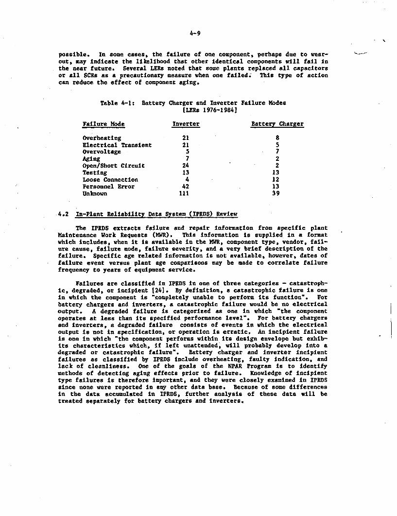
4-9
possible. In some cases, the failure of one component, perhaps due to wear-out, may indicate the likelihood that other identical components will fail inthe near future. Several LERs noted that some plants replaced all capacitorsor all SCRs as a precautionary measure when one failed; This type of actioncan reduce the effect of component aging.
Table 4-1: Battery Charger and Inverter Failure Modes[LERs 1976-19841
Failure Mode Inverter Battery Charger
Overheating 21 8Electrical Transient 21 5Overvoltage 5 7Aging 7 2Open/Short Circuit 24 2Testing 13 13Loose Connection 4 12Personnel Error 42 13Unknown 111 39
-4.2 In-Plant Reliability Data System (IPRDS) Review
The IPRDS extracts failure and repair information from specific plantMaintenance Work Requests (MWR). This information Is supplied in a formatwhich includes, when it is available in the MWE, component type, vendor, fail-ure cause, failure mode, failure severity, and a very brief description of thefailure. Specific age related Information is not available, however, dates offailure event versus plant age comparisons may be made to correlate failurefrequency to years of equipment service.
Failures are classified In IPRDS in one of three categories - catastroph-ic, degraded, or incipient 124]. By definition, a catastrophic failure is onein which the component is "completely unable to perform its function". Forbattery chargers and inverters, a catastrophic failure would be no electricaloutput. A degraded failure is categorized as one in which "the componentoperates at less than its specified performance level". For battery chargersand inverters, a degraded failure consists of events in which the electricaloutput is not in specification, or operation is erratic. An incipient failureis one in which "the component performs within its design envelope but exhib-its characteristics which, if left unattended, will probably develop Into adegraded or catastrophic failure". Battery charger and inverter incipientfailures as classified by IPRDS include overheating, faulty indication, andlack of cleanliness. One of the goals of the NPAR Program is to identifymethods of detecting aging effects prior to failure. Knowledge of incipienttype failures is therefore important, and they were closely examined in IPRDSsince none were reported in any other data base. Because of some differencesin the data accumulated in IPRDS, further analysis of these data will betreated separately for battery chargers and inverters.
-
4-10
4.2.1 Battery Charger IPRDS-Data
The IPRDS battery charger data reviewed consisted of 50 failure eventsreported by five nuclear facilities over the period from 1974 to 1981. Ofthese events 12 failures were classified as catastrophic, 25 degraded, and13 as incipient. Data summaries are displayed graphically in Figures 4-7 and4-8 and by specific failure causes in Table 4-2. From these summaries thefollowing conclusions may be drawn.
* Failure rate increases with plant age.
* A limited number of component types, namely relays, fuses, capacitorsand diodes account for the majority (27 of 45) of the hardware re-lated failures. This input is particularly important for focusinginspection, surveillance, and monitoring methods.
Analysis of the 1PRDS data reveals the following:
* Figure 4-7 graphically depicts the catastrophic failures recorded forthe five facilities. This type of failure results in a loss of thesafety related equipment but affects safety only if the battery has alow capacity. Such failures require plant actions including proceed-ing in an orderly manner to a shutdown condition. The time frame forcompleting such action coincides with the ampere-hour rating of thebattery. Figure 4-7 illustrates an increasing failure rate as theplant ages, with 10 of the 12 events occurring in years 3, 4, and 5.
<4 - o05
am 2 /
,, I A / * -
PLANT AGE -YEARS
Figure 4-7: Battery Charger Catastrophic Failure/Age Correlation[IPRDS 1974-1981]
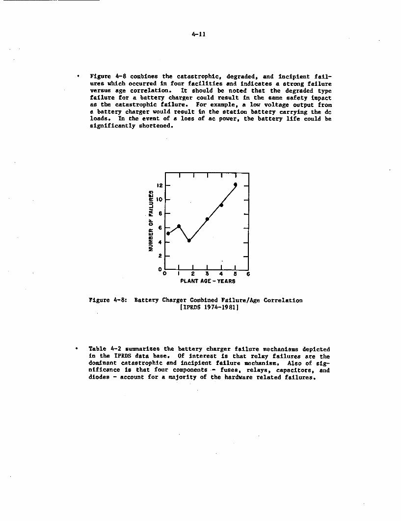
4-11
* Figure 4-8 combines the catastrophic, degraded, and incipient fail-ures which occurred in four facilities and indicates a strong failureversus age correlation. It should be noted that the degraded typefailure for a battery charger could result in the same safety impactas the catastrophic failure. For example, a low voltage output froma battery charger would result in the station battery carrying the dcloads. In the event of a loss of ac power, the battery life could besignificantly shortened.
12 -
0: 10 _/
0
0-
PLANT AGE - YEARS
Figure 4-8: Battery Charger Combined Failure/Age Correlation[IPRDS 1974-19811
* Table 4-2 summarizes the battery charger failure mechanisms depictedin the IPRDS data base. Of interest is that relay failures are thedominant catastrophic and incipient failure mechanism. Also of sig-nificance is that four components - fuses, relays, capacitors, anddiodes - account for a majority of the hardware related failures.
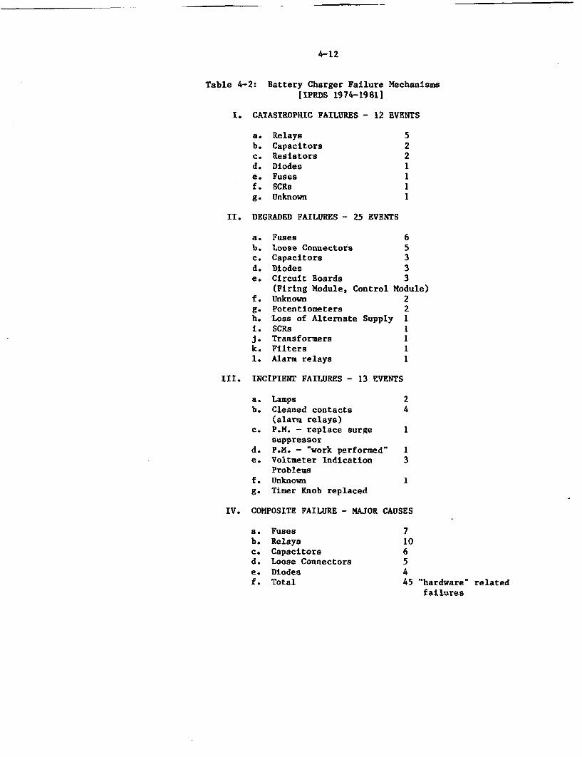
-
4-12
Table 4-2: Battery Charger Failure MechanismsIIPRDS 1974-19B11
I. CATASTROPHIC FAILURES - 12 EVENTS
a. Relays 5b. Capacitors 2c. Resistors 2d. Diodes 1e. Fuses 1f. SCRs 1g. Unknown 1
II. DEGRADED FAILURES - 25 EVENTS
a. Fuses 6b. Loose Connectors 5c. Capacitors 3d. Diodes 3e. Circuit Boards 3
(Firing Module, Control Module)f. Unknown 2g. Potentiometers 2h. Loss of Alternate Supply 1i. SCRs IJ. Transformers Ik. Filters 11. Alarm relays 1
III. INCIPIENT FAILURES - 13 EVENTS
a. Lamps 2b. Cleaned contacts 4
(alarm relays)c. P.M. - replace surge 1
suppressord. P.M. - "work performed" 1e. Voltmeter Indication 3
Problemsf. Unknown 1g. Timer Knob replaced
IV. COMPOSITE FAILURE - MAJOR CAUSES
a. Fuses 7b. Relays 10c. Capacitors 6d. Loose Connectors 5e. Diodes 4f. Total 45 "hardware" related
failures
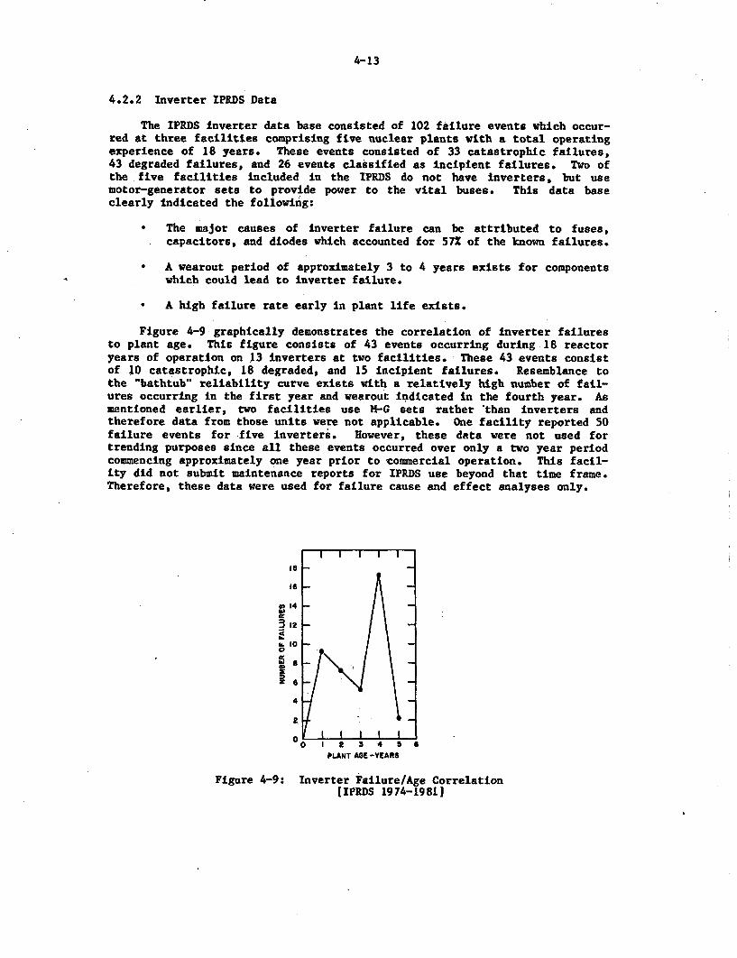
4-13
4.2.2 Inverter IPRDS Data
The IPRDS Inverter data base consisted of 102 failure events which occur-red at three facilities comprising five nuclear plants with a total operatingexperience of 18 years. These events consisted of 33 catastrophic failures,43 degraded failures, and 26 events classified as incipient failures. Two ofthe five facilities Included in the IPRDS do not have inverters, but usemotor-generator sets to provide power to the vital buses. This data baseclearly indicated the following:
* The major causes of inverter failure can be attributed to fuses,capacitors, and diodes which accounted for 57% of the known failures.
* A wearout period of approximately 3 to 4 years exists for componentswhich could lead to inverter failure.
* A high failure rate early in plant life exists.
Figure 4-9 graphically demonstrates the correlation of inverter failuresto plant age. This figure consists of 43 events occurring during 18 reactoryears of operation on 13 inverters at two facilities. These 43 events consistof 10 catastrophic, 18 degraded, and 15 Incipient failures. Resemblance tothe bathtub" reliability curve exists with a relatively high number of fail-ures occurring in the first year and wearout indicated in the fourth year. Asmentioned earlier, two facilities use H-G sets rather 'than inverters andtherefore data from those units were not applicable. One facility reported 50failure events for five inverters. However, these data were not used fortrending purposes since all these events occurred over only a two year periodcommencing approximately one year prior to commercial operation. This facil-ity did not submit maintenance reports for IPRDS use beyond that time frame.Therefore, these data were used for failure cause and effect analyses only.
14
-J12
.100
ze6
4
1 2 3 4 5 6PLANT AGE-YEARS
Figure 4-9: Inverter Failure/Age Correlation[IPRDS 1974-1981
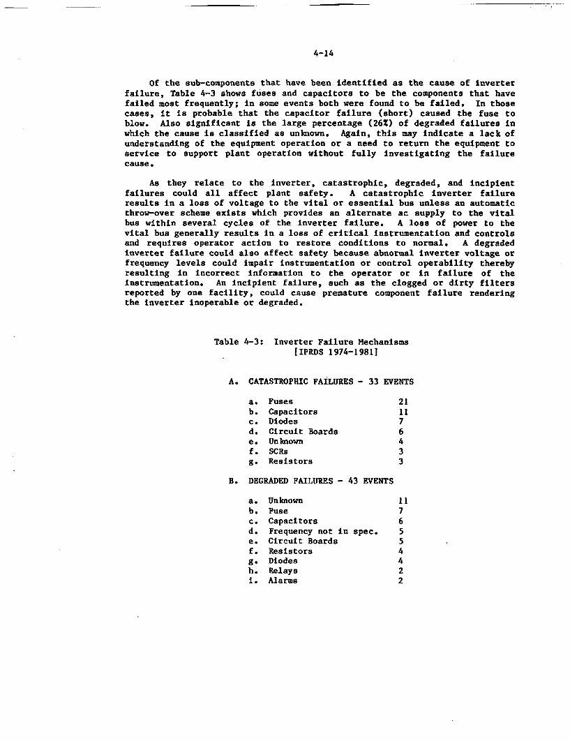
4-14
Of the sub-components that have been identified as the cause of inverterfailure, Table 4-3 shows fuses and capacitors to be the components that havefailed most frequently; in some events both were found to be failed. In thosecases, it is probable that the capacitor failure (short) caused the fuse toblow. Also significant is the large percentage (26%) of degraded failures inwhich the cause is classified as unknown. Again, this may indicate a lack ofunderstanding of the equipment operation or a need to return the equipment toservice to support plant operation without fully investigating the failurecause.
As they relate to the inverter, catastrophic, degraded, and incipientfailures could all affect plant safety. A catastrophic inverter failureresults in a loss of voltage to the vital or essential bus unless an automaticthrow-over scheme exists which provides an alternate ac supply to the vitalbus within several cycles of the inverter failure. A loss of power to thevital bus generally results in a loss of critical instrumentation and controlsand requires operator action to restore conditions to normal. A degradedinverter failure could also affect safety because abnormal inverter voltage orfrequency levels could impair instrumentation or control operability therebyresulting in incorrect information to the operator or in failure of theinstrumentation. An incipient failure, such as the clogged or dirty filtersreported by one facility, could cause premature component failure renderingthe inverter inoperable or degraded.
Table 4-3: Inverter Failure MechanismsLIPRDS 1974-19811
A. CATASTROPHIC FAILURES - 33 EVENTS
a. Fuses 21b. Capacitors 11c. Diodes 7d. Circuit Boards 6e. Unknown 4f. SCRs 3g. Resistors 3
B. DEGRADED FAILURES - 43 EVENTS
a. Unknown 11b. Fuse 7c. Capacitors 6d. Frequency not in spec. 5e. Circuit Boards 5f. Resistors 4g. Diodes 4h. Relays 2i. Alarms 2
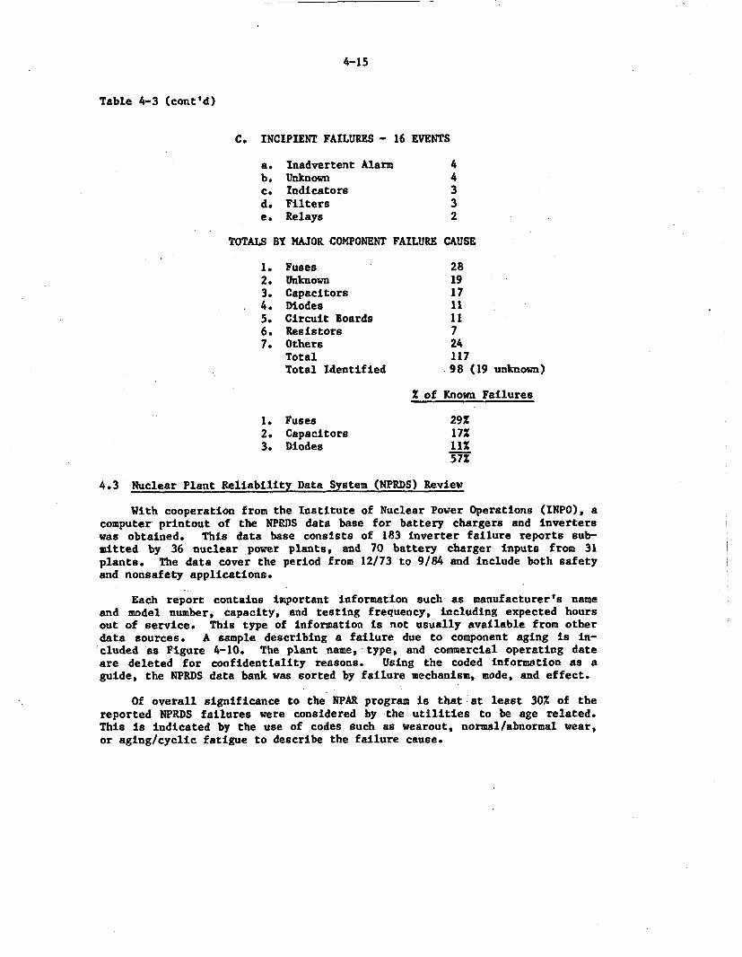
4-15
Table 4-3 (cont'd)
C. INCIPIENT FAILURES - 16 EVENTS
a. Inadvertent Alarm 4b. Unknown 4c. Indicators 3d. Filters 3e. Relays 2
TOTALS BY MAJOR COMPONENT FAILURE CAUSE
1. Fuses 282. Unknown 193. Capacitors 174. Diodes 115. Circuit Boards 116. Resistors 77. Others 24
Total 117Total Identified -98 (19 unknown)
2 of Known Failures
1. Fuses 29Z2. Capacitors 17%3. Diodes 11X
57X
4.3 Nuclear Plant Reliability Data System (NPRDS) Review
With cooperation from the Institute of Nuclear Power Operations (INPO), acomputer printout of the NPRDS data base for battery chargers and inverterswas obtained. This data base consists of 183 inverter failure reports sub-mitted by 36 nuclear power plants, and 70 battery charger inputs from 31plants. The data cover the period from 12/73 to 9/84 and include both safetyand nonsafety applications.
Each report contains important information such as manufacturer's nameand model number, capacity, and testing frequency, including expected hoursout of service. This type of information is not usually available from otherdata sources. A sample describing a failure due to component aging is in-cluded as Figure 4-10. The plant name, type, and commercial operating dateare deleted for confidentiality reasons. Using the coded information as aguide, the NPRDS data bank was sorted by failure mechanism, mode, and effect.
Of overall significance to the NPAR program is that at least 30% of thereported NPRDS failures were considered by the utilities to be age related.This Is indicated by the use of codes such as wearout, normal/abnormal wear,or aging/cyclic fatigue to describe the failure cause.
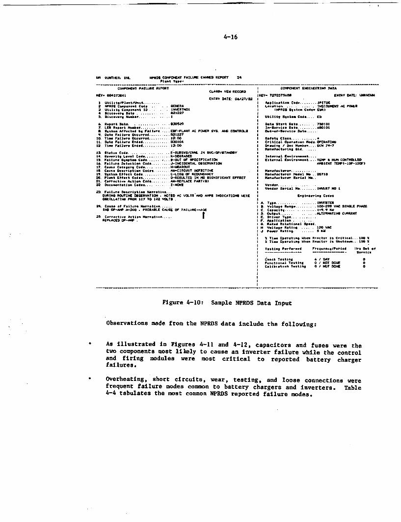
4-16
iln GUNTHER, SNL NPRDS COI'POENT FAILURE CANNED REPORT 24Plant TaPe-
---------------- - - ------ - ---------- - ---- - - ---- - - - ----- - - - ------- - ----- - --- -___C01PONEN1 FAILURE REPORT
KEV-80453941CLASS- NEW RECORDIIEY. 5X457394*
ENTRY DATE: 0&i17/831 Utilitg/PiantiUnst.2 PRDS Cp..sonnt Cede GENERA3 Utlsltl Coeeon~t ID INVERTNOI4. Dilcoer Date .0212275. Ditce'rg Nuher . .. I
6 Report Dot ..305207. LEII Resrt Nus .. .r. 60tta Affected h1 Fellre . EDF-PLANT AC POWER SY. AND CONTROLS9. Data Failure Occurred . 21227
10. Tier Failure Occurred . 2:0011. Date Failure Ended .3010412. Tia- Failure Ended .1:00
1l Status Cde .... ... ... ... .. E-SUMSYSOCd*. IN SVCDOPYSTANDRY14. Sev-eitl Lvel Cde . K-DEGRADED15. Failu.r S9apte4 Code ... . S-OUT OF SPECIFICATION16. Failuea Detection Cod . J-INCIDENTAL OBSERVATION17. Cause Cace.9rl Code .H-JEAROUTIS Caus DesPcrition Codes . -CIRCUIT DEFECTIVE19. Sustea Eflect Cod .C-LOSS OF REDUNDANCY20. Plant EPfect Codes. O-RESULTEO IN NO SIGNIFICANT EFFECT21. Corractiue Actlen Coda .. -REPLACE PART4S)22 Documeniation Cdes .2--NONE
23. Failure Description NarraticeDURING ROUTINE OBSERVATION . NOTED AC VGLTS AND MIPS INDICATIONS WEREOSCILLATING FRON 117 TO 122 VOLTS
24. Couse of Failure Marrativ.BAD OP-ANP H-200 . PROBABLE CAS OF FAILURE--AGE
25 Curractia Actio. Na rat tREPLACED OP-"P .
I COPIPONENT ENGINEERING DATA
IIIEV- 7270375600 ENTRY DATE: UNI
I Application Cod . IPITGEI Location. INSiUREDT AC POWlERI IICROS Sqst,. Cede. EKII
I UtiltV Sgotea Cede.... E%
I Data Start Date. 750101I In-Rertc.1 Date .at. 0.I O.,R-of-S e rvl Data .
I Safotg Class4 ,I Critical Operation Mode. .OCATINSI Drawing / Doc Much.,.. .. D00 74-7I Manufacturing id......
I Int..nal EnuironoantI Eaternal Envirenoant . TEnrP F HUM CONTROLLEDI PANlENT TEIPI-IOF-l2oF)
ONon
I . nuia tu" rI r .Il-nu pahs rwer Model No .2071SManufacturer Serial N..
IVender.IVendr Serial N. . INVERT No I
Englneering Codes
A T .. p. . INVERTERIS VoltaB Rnge 100-2W VAC SINGLE PHASE
Ic. Cpc.itg .... . 1-10. 1.DI Dutput.A LTERNATING CURRENT.E D'rlv T~jeF Application.0. Rated Rotational SpeedII Voltave Rati ... 120 VACJ Perer Rating... KUI
21 Tie Oeratng Ilk:n R cttor 1s Critical.. 100 XI Ti OparaltnI Whn Reactor is Sktde.. 100 X
Testing Perfre..d Frcq..cnc/PerLod lire Dut eP- -- - ---- --- ---- S- 9 nic e
iChck Testing & / DAY 0Funetional Tenting 0 / NOT DONE 0Calibration Tosting 0 / NOT DONE 0
Figure 4-10: Sample NPRDS Data Input
Observations made from the NPRDS data include the following:
* As illustrated in Figures 4-11 and 4-12, capacitors and fuses were thetwo components most likely to cause an inverter failure while the controland firing modules were most critical to reported battery chargerfailures.
Overheating, short circuits, wear, testing, and loose connections werefrequent failure modes common to battery chargers and inverters. Table4-4 tabulates the most common NPRDS reported failure modes.
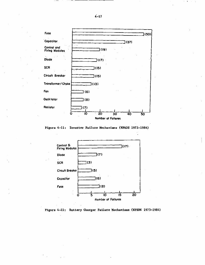
4-17
Fuse
Capacitor
Control andFiring Modules
Diode
SCR
Circuit Breaker
Transformer/ Choke
Fan
Oscil lator
Resistor
- --
--- 1(37)
- 1(19)
(107)
(15)
'(15)
(13)
(8)
- ] (8)
t(7)I - II I
--- -- -
0 10 '20 30Number of Failures
40 50
Figure 4-11: Inverter Failure Mechanisms (NPRDS 1973-1984)
.
Control 8Firing Modules
Diode
SCR
Circuit Breaker I
1(17) -
1((7
I (3)
I (5)
1 (6)
i (8)
lI I l I
Capacitor
Fuse
0 5 10 15Number of Failures
20
Figure 4-12: Battery Charger Failure Mechanisms (KPRDS 1973-1984)
4-18
According to INPO, as of mid 1984 all of the participating units are sub-mitting failure data to NPRDS in a uniform format that can be easily input tothe computer. This industry commitment should make the NPRDS data bank anexcellent source of equipment failure data in the future. Conclusions drawnfrom the present data base must be qualified for several reasons. For in-stance, there is some overlap with the LER data base. This overlap consistedof 32 of the 183 inverter failure reports (17%) and 17 of the 70 batterycharger reports (24%). Secondly, the NPRDS data bank consisted of failurereports from only 36 units for inverters and 31 units for battery chargers.Based on a comparison of the LER and IPRDS data reviewed, it is apparent thatsome plants were not fully documenting failures on inverters and chargers tothe NPRDS data bank prior to 1984. Since then, however, INPO has published aReportable Scope Manual that provides a uniform definition of which equipmentis to be reported. Battery chargers and inverters are included in this Manualand are reported to NPRDS. Finally, only limited time domain analysis (plantage versus failure rate) can be performed using this data base since utilityparticipation in this program was not consistent over the entire study period.For instance, five plants that went critical in the early 1970s did not beginreporting failures until 1983.
Table 4-4: Battery Charger and Inverter Failure Modes[NPRDS 1973-19841
Failure Mode Inverter Battery Charger
Overheating 14 3Short Circuit 13 4Aging/Wear 11 6Testing 9 7Loose Connections 9 10Personnel Error 11 3
Past NPRDS annual reports were also reviewed to obtain reliabilityinformation and to determine the importance of charger/inverter failuresrelative to other component failures. Perhaps the most significant summariesprovided by the 1983 NPRDS annual report deal with major component types whichaffect safety system operation. It is of concern that inverter and/or batterycharger failures are high on the list of many important safety systems asdescribed below.
A summary of the failures of the Reactor Protection Systems (RPS) andsafeguards instrumentation systems employed at plants (Figure 4-13) indicatedthat inverter failure was the highest contributor of all the major componenttypes which make up the systems. In fact, the NPRDS failure rate forinverters is nearly as high as that of all the other components combined. Asverified in LER reports, inverter failures have resulted in reactor trips andsafety injection system actuations. While "fail safe' in philosophy, theseevents certainly challenge the safety systems and place the plants in atransient condition which could contribute to additional equipment failures orimpact plant life. Reactor pressure vessels, for instance, are designed for alimited number of transients.
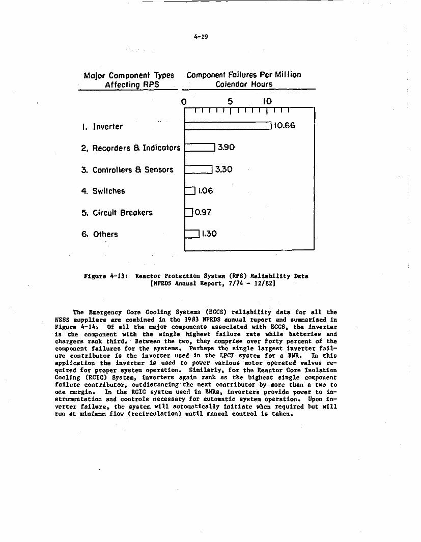
4-19
Major Component TypesAffecting RPS ^
Component Failures Per MillionCalendar Hours
0
1. Inverter
2. Recorders a Indicators _
3. Controllers a Sensors
4. Switches
5. Circuit Breakers
6. Others
5 l0I I1 g1 1 1 1 1 1 1 1 I
10.66
3.90
3.30
J 1.06
3 0.97
-1.30
Figure 4-13: Reactor Protection System (RPS) Reliability Data!NPRDS Annual Report, 7/74 - 12/821
The Emergency Core Cooling Systems (ECCS) reliability data for all theNSSS suppliers are combined in the 1983 NPRDS annual report and summarized inFigure 4-14. Of all the major components associated with ECCS, the inverteris the component with the single highest failure rate while batteries andchargers rank third. Between the two, they comprise over forty percent of thecomponent failures for the systems. Perhaps the single largest inverter fail-ure contributor is the inverter used in the LPCI system for a BWR. In thisapplication the inverter is used to power various motor operated valves re-quired for proper system operation. Similarly, for the Reactor Core IsolationCooling (RCIC) System, inverters again rank as the highest single componentfailure contributor, outdistancing the next contributor by more than a two toone margin. In the RCIC system used in MW~s, inverters provide power to in-strumentation and controls necessary for automatic system operation. Upon in-verter failure, the system will automatically initiate when required but willrun at minimum flow (recirculation) until manual control is taken.
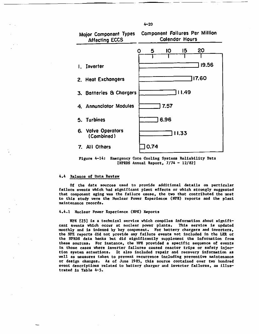
4-20
Major Component TypesAffecting ECCS
1. Inverter
2. Heat Exchangers
3. Batteries a Chargers
4. Annunciator Modules
5. Turbines
6. Valve Operators(Combined)
7. Al I Others
Component Failures Per MillionCalendar Hours
O 5 10 15 20
j Z1 19.56
117.60
; lZJ 11.49
17.57
6.96
111.33
- 0.74
Figure 4-14: Emergency Core Cooling Systems Reliability Data[NPRDS Annual Report, 7/74 - 12/82]
4.4 Balance of Data Review
Of the data sources used to provide additional details on particularfailure events which had significant plant effects or which strongly suggestedthat component aging was the failure cause, the two that contributed the mostto this study were the Nuclear Power Experience (NPE) reports and the plantmaintenance records.
4.4.1 Nuclear Power Experience (NPE) Reports
NPE 125] is a technical service which compiles information about signifi-cant events which occur at nuclear power plants. This service is updatedmonthly and is indexed by key component. For battery chargers and inverters,the NPE reports did not provide any failure events not included in the LER orthe NPRDS data banks but did significantly supplement the information fromthese sources. For instance, the NPE provided a specific sequence of eventsin those cases where inverter failures caused reactor trips or safety injec-tion system actuations. It also included repair and recovery information aswell as measures taken to prevent recurrence including preventive maintenanceor design changes. As of June 1985, this source contained over two hundredevent descriptions related to battery charger and inverter failures, as illus-trated in Table 4-5.
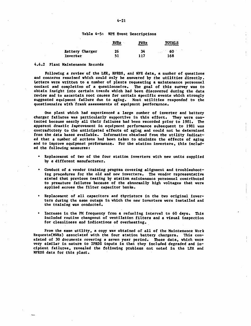
4-21
Table 4-5: NPE Event Descriptions
BWRs PWRs TOTALS
Battery Charger 26 34 -60Inverter 51 117 168
4.4.2 Plant Maintenance Records
Following a review of the LER, NPRDS, and NPE data, a number of questionsand concerns remained which could only be answered by the utilities directly.Letters were written to a number of plants requesting a maintenance personnelcontact and completion of a questionnaire. The goal of this survey was toobtain insight into certain trends which had been discovered during the datareview and to ascertain root causes for certain specific events which stronglysuggested equipment failure due to aging. Most utilities responded to thequestionnaire with frank assessments of equipment performance.
One plant which had experienced a large number of inverter and batterycharger failures was particularly supportive in this effort. They were con-tacted because nearly all their failures had been recorded prior to 1981. Theapparent drastic improvement In equipment performance subsequent to 1981 wascontradictory to the anticipated effects of aging and could not be determinedfrom the data bases available. Information obtained from the utility indicat-ed that a number of actions had been taken to minimize the effects of agingand to improve equipment performance. For the station inverters, this includ-ed the following measures:
* Replacement of two of the four station inverters with new units suppliedby a different manufacturer.
* Conduct of a vendor training program covering alignment and troubleshoot-ing procedures for the old and new inverters. The vendor representativestated that previous testing by station maintenance personnel contributedto premature failures because of the abnormally high voltages that wereapplied across the filter capacitor banks.
* Replacement of all capacitors and thyristors in the two original Inver-ters during the same outage in which the new Inverters were installed andthe training was conducted.
* Increase In the PM frequency from a refueling interval to 60 days. Thisincluded routine changeout of ventilation filters and a visual inspectionfor cleanliness and indications of overheating.
From the same utility, a copy was obtained of all of the Maintenance WorkRequests(MWRs) associated with the four station battery chargers. This con-sisted of 30 documents covering a seven year period. These data, which werevery similar in nature to IPRDS inputs in that they included degraded and in-cipient failures, revealed the following problems not noted in the LER andNPRDS data for this plant.
4-22
* Six MWRs addressed equalizing timer problems including contact pittingand timer mechanism 'sticking". The equalizing timer controls the timethat a charging voltage is applied to the battery and automatically re-verts the charger to a "float' mode upon completion of the charge. Atimer failure could result in battery damage due to grid corrosion or ex-cessive gassing. Overcharging also increases the battery temperaturewhich may lead to plate buckling [261.
* Several incidents of the equalize voltage drifting high were encountered.Adjustment of a potentiometer was required to correct this conditionwhich could affect equipment supplied by the dc bus. In fact, reactortrips occurred at two different facilities as a result of inverter cir-cuit breaker trips due to high input voltage from the charger.
* Heat generated in the charger cabinet caused degradation of the controland power cable and required replacement with cable having an operatingtemperature rating of 90C ("GE VULKENE SIS-7275 or equivalent").
Likewise, another plant was contacted because in its long history ofoperation no LERs had been discovered for inverters or battery charger fail-ures. Response from the utility revealed that nine inverter failures on theoriginal two station inverters had led to several reactor trips and systemtransients. "After many more problems, these inverters were replaced ...The replacement inverters are a solid-state design with an automatic staticthrowover switch, and a manual maintenance bypass switch which permits main-tenance personnel to perform required PM during normal plant operation. 'Con-stant monitoring" by the operating personnel is also credited with improvingequipment performances. The only subsequent failures were related to indicat-ing lights, a synchronizing board, and an oscillator board, none of whichresulted in loss of the vital bus.
This same plant has made a number of changes in their battery chargers,including provision of cross tie capability to a nonsafety related charger. Alater NRC ruling based on Regulatory 1.6 limited the use of this cross tie toshutdown conditions. Therefore, this utility is in the process of installinga second 100% capacity charger on each dc bus to improve reliability andavailability. No aging related failures have been noted on the original unitsaccording to the electrical supervisor.
Other important information on charger and inverter failure causes andeffects obtained from utility contacts include the following:
* Inverter trips during Emergency Diesel Generator (EDG) testing have beencaused by frequency and voltage swings that occur as loads are picked upby the EDG. Under actual emergency conditions, the inverter would nor-mally have switched to the battery as an input before the EDG coming onthe bus.
* One utility stated that they had replaced all of the capacitors with onehaving a higher dielectric strength and a higher temperature rating. Imrproved battery charger performance resulted.
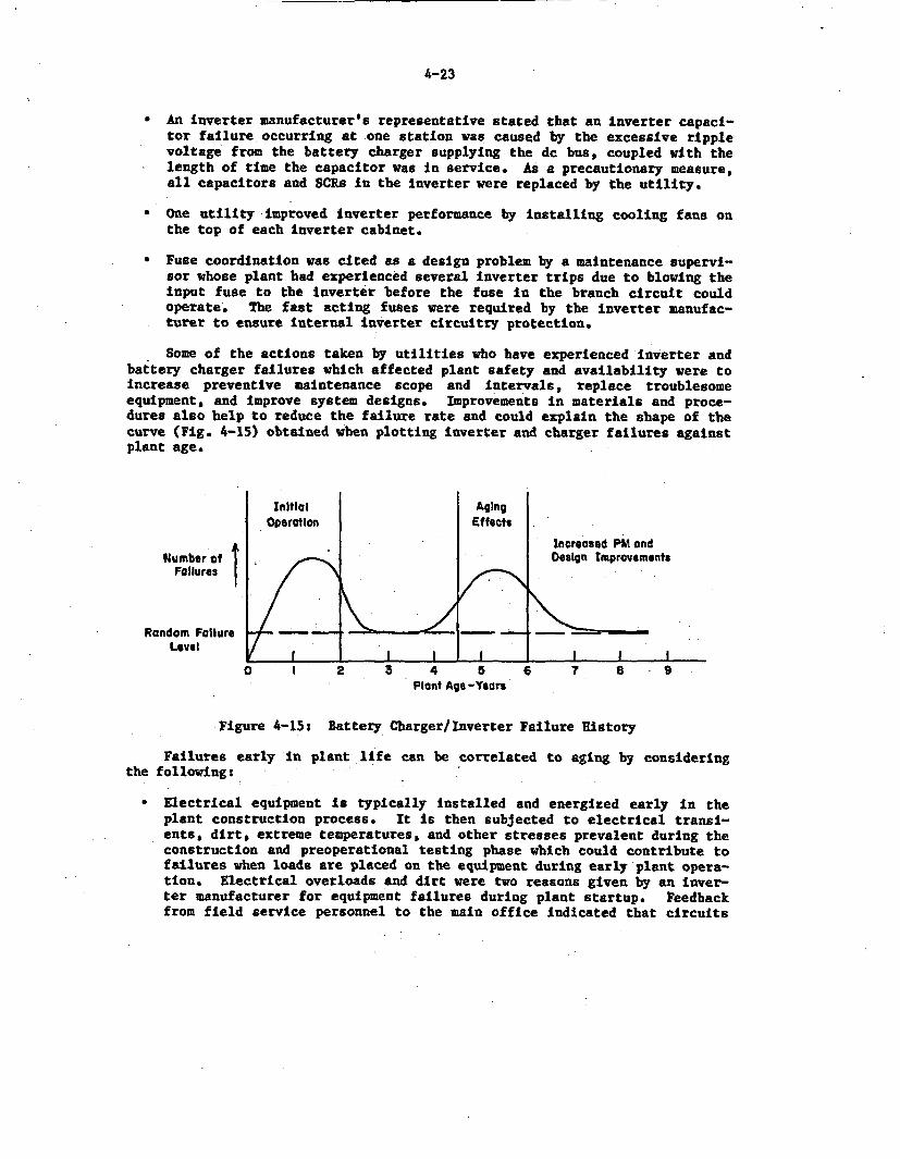
4-23
* An inverter manufacturer's representative stated that an Inverter capaci-tor failure occurring at one station was caused by the excessive ripplevoltage from the battery charger supplying the dc bus, coupled with the
* length of time the capacitor was In service. As a precautionary measure,all capacitors and SCRs in the inverter were replaced by the utility.
* One utility improved inverter performance by installing cooling fans onthe top of each inverter cabinet.
* Fuse coordination was cited as a design problem by a maintenance supervi-sor whose plant had experienced several inverter trips due to blowing theinput fuse to the inverter before the fuse in the branch circuit couldoperate. The fast acting fuses were required by the inverter manufac-turer to ensure internal inverter circuitry protection.
Some of the actions taken by utilities who have experienced inverter andbattery charger failures which affected plant safety and availability were toincrease preventive maintenance scope and intervals, replace troublesomeequipment, and improve system designs. Improvements in materials and proce-dures also help to reduce the failure rate and could explain the shape of thecurve (Fig. 4-15) obtained when plotting inverter and charger failures againstplant age.
Initial AgingOperation Effects
Increased PM andNumber of Design Improvements
Failures
Random Failure - -l _Level
0 l 2 3 4 5 6 7 a -Plant Age -Years
Figure 4-15: Battery Charger/Inverter Failure History
Failures early in plant life can be correlated to aging by consideringthe following:
* Electrical equipment is typically installed and energized early in theplant construction process. It Is then subjected to electrical transi-ents, dirt, extreme temperatures, and other stresses prevalent during theconstruction and preoperational testing phase which could contribute tofailures when loads are placed on the equipment during early plant opera-tion. Electrical overloads and dirt were two reasons given by an Inver-ter manufacturer for equipment failures during plant startup. Feedbackfrom field service personnel to the main office indicated that circuits
4-24
had been subjected to extreme overload conditions due to the lack of iso-lation when testing adjoining electrical equipment (such as circuitbreaker testing).
* Unfamiliarity with equipment operation can lead to personnel errors dur-ing operation or testing of the chargers and inverters. This may in-directly lead to premature equipment failure if degradation is not recog-nized.
* Long construction times typical of nuclear plants coming on line recentlycould contribute to failures occurring early in plant life because of theaging effects associated with equipment 'storage". Moisture intrusion ofkey components during construction could lead to premature equipmentfailure.
4.5 Other Information Sources Including Published Reports
A number of other sources were consulted to obtain background informationabout battery charger and inverter operation, components, and testing. Someof these are described below.
4.5.1 NSAC/44; Investigations of Failures in I&C Power Supply Hardware [3]
This report studied instrument (vital) bus failures which caused reactortrips and identified inverter failures as the biggest contributor to the un-availability of Instrument and Control (I&C) power supplies. Additionally,this report identified excessive temperatures, currents, and voltages as themost common causes of inverter failures with capacitors and fuses being thecomponents most susceptible to failure. The effect of design differences, busconfigurations, system interactions, and analysis of components such as SCRs,diodes, and circuit boards was not covered in this study.
4.5.2 NUREG/CR-3808; Aging-Seismic Correlation Study on Class 1EEquipment [201
This report presents a method for evaluating the aging/seismic effects inelectrical equipment. According to this study, the primary failure mode at-tributed to battery chargers under seismic stress is the failure of relays dueto fatigue and coil insulation degradation common to relays as well as otherelectromechanical devices. Additional failures with capacitors and circuitboard assemblies could occur because of connector fatigue due to the vibrationand thermal stresses. Furthermore, this report states that semiconductordevices such as diodes and transistors may experience failure accelerationbecause of the seismic vibration causing cracks to grow in the encapsulant,thereby permitting moisture and oxygen to enter and promote corrosion of thecircuitry.
4.5.3 NUREG/CR-3156; A Survey of the State-of-the-Art in Aging of ElectronicsWith Application to Nuclear Power Plant Instrumentation [27]
This study evaluated the performance of electronic components in nuclearpower plants. While primarily concerned with the effects of radiation on
4-25
electronic devices, the report also discusses general aging characteristicsand mechanisms of electronics similar to those used in battery chargez andinverter designs. This report concludes that "semiconductor devices and inte-grated circuits are probably the most environmentally and operationally sensi-tive electronic components.' Because this report focuses on the survivabilityof components in containment environments, not all its conclusions are rele-vant to battery chargers and Inverters which are located in mild environments.
4.5.4 Vendor Input
A tour of the Power Conversion Products (PCP) facilities in Illinois anddiscussions with PCP personnel regarding battery charger construction, mater-ials, and operating characteristics provided background information necessaryto understand the various failure data analyzed. PCP has tested a prototypecharger in accordance with IEEE 650-1979 and permitted BNL to make a closeexamination of the prototype while providing a detailed description of thevarious aspects of the test program. Design modification information andfield equipment service experiences were also supplied.
A tour of the Elgar facilities in San Diego and discussions with Elgarpersonnel covering acceptance testing, qualification analyses, and equipmentoperating experiences contributed greatly to understanding the current state-of-the-art in inverter design and construction. This company began manufac-turing inverters for nuclear power plants in 1979 and is currently involvedin a number of plant startups. Feedback on initial equipment performance wasobtained from Elgar.
Manufacturer information including sample qualification reports, schema-tics, operating instructions, and recommended maintenance and storage proce-dures was solicited from past and present suppliers of battery chargers andinverters to nuclear power plants. This information was essential for learn-ing the differences in designs and the details of the components used, thesizes and ratings of the equipment, and any limitations or warnings offered bythe vendor.
4.6 Failure Modes/Mechanisms/Causes
Table 4-6 is a culmination of the review and analysis of operating exper-iences, applicable reports, manufacturer instruction and maintenance manuals,and equipment materials. It also indicates potential aging-seismic correla-tion, and identifies the failure category. Terms used to organize and classi-fy the information presented in the table are defined below:
* FAILURE MODES indicate the basic manner in which the battery chargeror inverter fails.
* FAILURE MECHANISMS details the materials and parts of the equipmentaffected by degradation thereby causing the malfunction to occur.
* FAILURE CAUSES explains the actual malfunction by describing themanner in which inverter/charger components degrade, short, open,overheat, burn (etc.) and thereby create the failure mechanism.
4-26
* The AGING and AGING-SEISMIC CORRELATION categories Indicate whetherthe failure mode, mechanism, and cause are directly attributable orpotentially susceptible to time-related effects and externally in-duced effects, respectively.
* PROBABILITY OF OCCURRENCE indicates the likelihood of the correspond-ing failure to occur on the basis of the characteristics of the fail-ure cause and is assigned either a high, medium, or low probability.
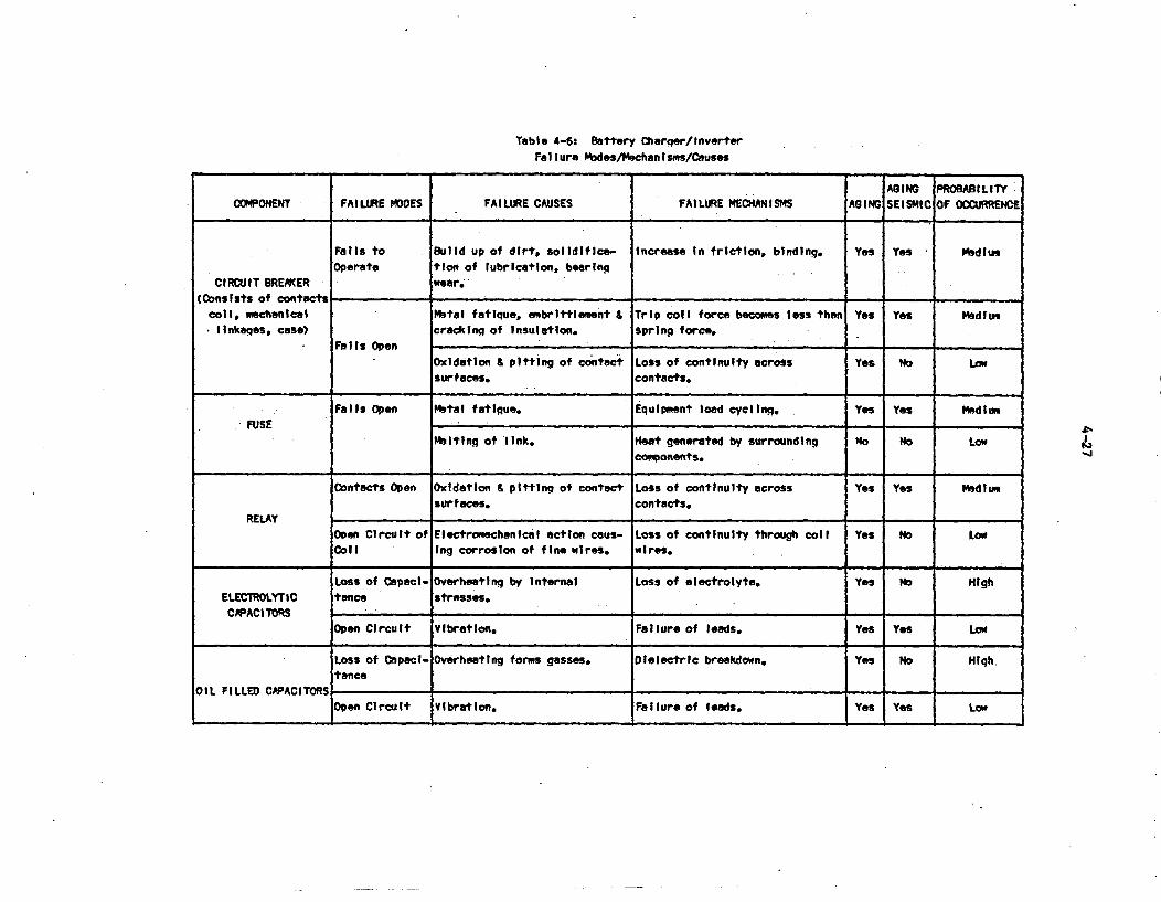
Table 4-6: Battery Charqsr/InverterFatilure Podes/Mochan Itiss/CIauS
AGING PROBABILITYCOMPONENT FAILURE MOOES FAILURE CAUSES FAILURE MECHANISMS AGING SEISMIC OF OCCURRENCE
Fails to Build up of dirt, solidiflea- increase In friction, binding. Yes Yes Medlum
Operate tion of lubrication, bearing
CIRCUIT BREAKER wear-.(Consists of contact _
Coil, mechanical Mbtal fatique, ambrittlement & Trip coil force becomes less than Yes Yes Medlumlinkages, case) cracking of Insulation. spring force.
Falls Open
Oxidation & pitting of contact Loss of continuity across Yes No Low
surfaces. contacts.
Falls Open Metal fatigue. Equipment load cycling. Yes Yes Medlum
FUSE
Melting of link. Heat generated by surrounding Mo No Lowconponents.
Contacts Open OxidatIon & pitting of contact Loss of continuIty across Yes Yes Medium
surfaces. contacts.RELAY
Open Circuit of Electromechanical action caus- Loss of continuity through coil Yes No Low
Coll Ing corrosion of fine wires. wires.
Loss of Capel- Overheating by Internal Loss of electrolyte. Yes No High
ELECTROLYTIC tance stresses.
CPPACITORSOpen Circuit Vibration. Failure of lfods. Yes Yes Low
Loss of Capecl- Overheating forms gasses. Dielectric breakdown. Yes No High.tance
OIL FILLED CAPACITORS_
Open CircuIt Vlbratlon. Failure of leads. Yes Yes Low
t'.-j
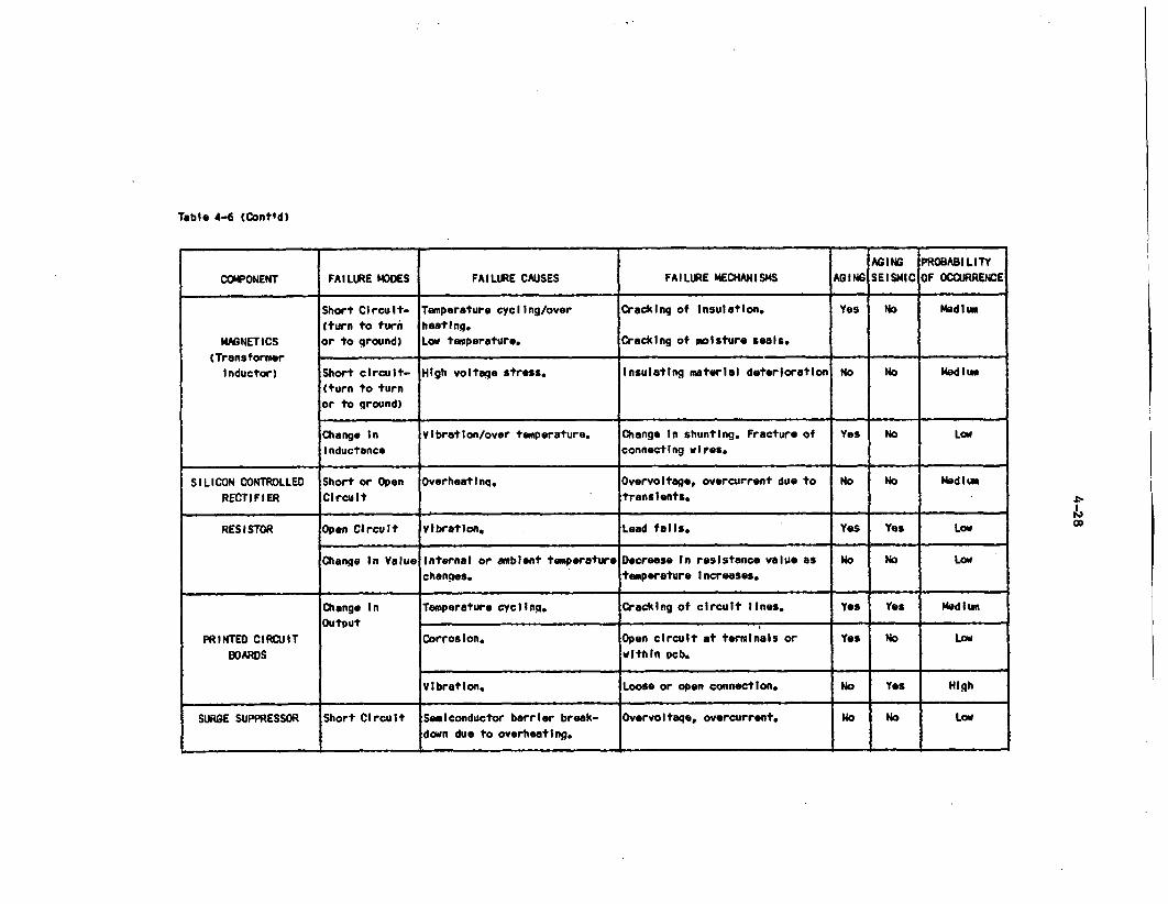
Table 4-6 (Cont'd)
AGING PROBABILITYCOMPONENT FAILURE MODES FAILURE CAUSES FAILURE MECHANISMS AGING SEISMIC OF OCCURRENCE
Short Circuit- Temperature cycling/over Cracking of Insulation. Yes No Madliu(turn to turi beating.
MMGNETICS or to ground) Low temperature. Cracking of moisture seals.(Transformer
Inductor) Short circuit- High voltage stress. Insulating material deterioration No No Medliu(turn to turnor to ground)
Change In Vibration/over temperature. Change In shunting. Fracture of Yes No LowInductance connecting wires.
SILICON CONTROLLED Short or Open Overheating. Overvoltage, overcurrent due to No NO MediumRECTIFIER CIrcuit transients.
RESISTOR Open Circuit Vibration. Lead fails. Yes Yes Low
Change In Value Internal or ambient temperature Decrease In resistance value as No No Lowchanges. temperature Increases.
Change In Temperature cycling. Cracking of circuit lines. yes Yes MediumOutput
PRINTED CIRCUIT Corrosion. Open circuit at terminals or Yes No LOwBOARDS within pcb.
Vibration. Loose or open connection. No Yes High
SURGE SUPPRESSOR Short Circuit Semiconductor barrier break- Overvoltaqe, overcurrent. No No Lowdown due to overheating.
.L-
16Co
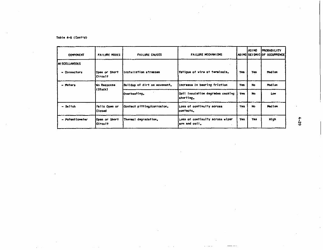
Table 4-6 (Cont'd)
AGING PROBABILITYCOMPONENT FAILURE MODES FAILURE CAUSES FAILURE MECHANISMS AGING SEISMIC OF OCCURRENCE
MISCELLANEOUS
- Connectors Open or Short Installation stresses Fatigue of wire at terminals. Yes Yes MediumCircuit
- Meters No Response Buildup of dirt on movement. Increase In bearing friction Yes No Medium(Stuck)
Overheating. Coll Insulation degrades causing Yes No LoWshorting.
- Switch Falls Open or Contact pitting/corrosion. Loss of continuity across Yes No MediumClosed contacts.
- Potentiometer Open or Short Thermal degradation. Loss of continuity across wiper Yes Yes HighCircuit arm and coil. '0
5-1
5.0 DISCUSSION OF CURRENT METHODS, TECHNOLOGY, AND REQUIREMENTS
A significant part of the aging assessment of any equipment is the evalu-ation of the equipment design and specifications; the review of industry prac-tices (standards) associated with the construction, installation, and testingof the equipment; and the monitoring, testing, and maintenance techniques ap-plied to mitigate equipment failure due to aging.
This section examines and summarizes available information covering theabove subjects including selected manufacturer operating and maintenance man-uals, IEEE standards, regulatory guides, and published reports. Informationregarding work in progress is also included to illustrate the ongoing interestand concerns in this area.
5.1 Equipment Design and Specifications
Vendor operating and maintenance manuals, product literature, and a de-tailed user's specification provided information on the design data and oper-ating requirements of the battery charger and the inverter. A number of im-portant parameters specified by the user are readily available in the manu-facturer's literature and include:
output voltage regulationfrequency controltotal harmonic distortionoperating temperature and humidity limitstransient responsepercent ripplecurrent limit capabilityefficiency
Other items stated in user specifications but sometimes treated asoptions by the manufacturers are:
meteringalarm contactsIndicating lightsenclosure specifications (wall, skid, bolted, welded)type of cooling (forced air or convection)electrical protectionvoltage and phase unbalance specs for three phase systems
Because of the combination of required and desired items, each nuclear inver-ter and battery charger is unique, although certainly the major circuitries ofeach are similar for the specific models and manufacturers.
For a typical nuclear inverter, the specifications may be described asfollows (these descriptions and the values provided have been taken from themanuals of several manufacturers):
5-2
* Voltage regulation is the variance in the output voltage and isnormally + 2% of the nominal voltage for output load variations andpower factor from 0.8 to 1.0, or + 1% for steady state, continuousloads.
* The output frequency is regulated to within 0.52 of nominal. Thisparameter requirement may vary with users; however, 0.5% is withinthe acceptable tolerance range of most loads that exist in safetyrelated applications. The output of the inverter may be synchro-nized with another source or with a frequency standard. The impe-dance, voltage variation, and transient noise capability of thesynchronizing signal to be used must be indicated in addition tothe frequency.
* One measure of the output sine wave from an inverter is the amountof harmonics of the fundamental frequency which are present. Thefundamental frequency is the component of lowest frequency andgreatest amplitude. Specifications usually require that no morethan 5% total harmonic distortion be allowed in the output sinewave with any one harmonic not exceeding 3%. As defined in IHEE-100-1977 [281, the total harmonic distortion is "the ratio of theroot-mean-square (rms) value of all the harmonics to the rms valueof the fundamental."
Some applications may not require the low harmonic outputs mentioned,especially if additional rectification or filtering is provided by the instru-ment power supplies being fed by the inverter. In fact, a square wave outputcould even be acceptable, although if a square wave inverter output is used inconjunction with external transformer loads, the transformers must be capableof handling the additional swing in flux (approximately 11%) without overheat-ing. The square wave transformer input increases the total core loss andcould lead to a temperature rise within the transformer which exceeds itsrated value at full load. In general, even though a wider harmonic distortiontolerance in the specification results in reduced inverter size, cost, andweight, the wide variety of nuclear inverter applications dictate that har-monic distortion levels be minimized to achieve required performance.
Efficiency is a measure of the power output divided by the inputpower. Depending upon the type of unit, efficiency can vary from80% to 90%. Generally, efficiency is not given a high priority innuclear power plant applications since the difference between aninverter system operating at 80% efficiency and another at 90% isnot a significant, or even measurable, part of the plant operatingcost. Reduced maintenance and service costs more than offset theminimal cost differences due to efficiency.
Voltage unbalance is the relationship of the voltage of one phasewith respect to each of the other two phases and is calculated bythe equation:
5-3
Unbalance (x) (maximum voltage - minimum voltage) x 100- Average voltage
The unbalance should be less than + 2% for balanced loads and lessthan + 5Z for 100% unbalanced loads.
- .1
* For a three phase system, the three phases should be shifted 120electrical degrees in relation to each other. A typical specifica-tion requires an unbalance of no more than 5 degrees from nominal.
Several inverter specifications state that up to a 125% overloadcan be carried continuously by the inverter although current limit-ing circuitry is operable for only a short time, typically tenseconds for overloads as high as 200%. Because of the overloadlimitations, it is important that the load characteristic be care-fully defined. Of specific importance are the load power factor,the load variation, and the maximum load to be switched at onetime. The possibility of load short circuits should also be con-sidered and fault clearing times factored into the current limitingrequirement.
Similarly, battery charger manufacturer specifications include standardterminology summarized as follows:
a Automatic 115% current limiting protection is important in anuclear application since the charger must be capable of recharginga depleted battery while supplying the emergency dc loads. Withoutthis feature, the load demand might lead to a charger overloadwhich could damage the charger or trip the input circuit breakerresulting in a loss of the dc bus.
* Output ripple no more than 2% rms when connected to a battery withan amp-hour capacity of four times the ampere output rating of thecharger is typically specified. Charger manufacturers offer opti-mal 30 or 100 millivolt rms ripple levels which are usually re-quired by the nuclear user specification. The additional filteringnecessary to reduce the ripple to these levels consists of capaci-tors and inductors. This filtering aspect makes nuclear relatedapplications somewhat different from the standard industrial modelswhich have minimal filtering.
a Output voltage should vary no more than + 1% from no load to fullload, with ac Input variations of + 10%, and an input frequencyrange of 57 to 63 Hz.
* Complete protection features Including input and output line fusesin series with the ac Input circuit breaker and dc output circuit
- breaker, semiconductor protective fuses, and power failure relayalarms.
5-4
In addition, specifications are sometimes included on the potentiometersused for float and equalize voltage adjustments such as requiring settings ad-justable to + 5Z.
Incorporated in the user specifications for battery chargers and Inver-ters are the ratings or sizes of the units to be provided. The minimum sizeis dictated by the safety related loads that must be available to mitigateaccident consequences as described in the plant Final Safety Analysis Report(FSAR).
As briefly discussed in Section 3.3, battery charger sizing is based on anumber of parameters including the continuous load on the dc system, the typeof batteries used, and the time required to recharge the battery to 95% capa-city-while simultaneously supplying the steady state dc load. Inherent inthis requirement is that the recharge voltage must be less than the maximumallowable dc system voltage unless the battery and charger can be isolatedfrom the dc system during recharging. In plants with a cross tie capability,there is evidence that this latter method has been used in the past. Equaliz-ing voltages required for the battery may exceed maximum voltages permissibleby the loads supplied from the dc bus, including the inverter or sensitiveprocess monitoring instrumentation. This problem may be circumvented byremoving one or two cells from the battery which lowers the required equal-izing voltage by several volts.
5.2 Standards, Guides, and Codes
User specifications for nuclear safety related battery chargers and in-verters reference three major industry standards for defining construction,design, and/or testing requirements. These are IEEE 650-1979, 'IEEE Standardfor Qualification of Class 1E Static Battery Chargers and Inverters forNuclear Power Generating Stations," NEMA PE 5-1983, 'Constant Potential-TypeElectric Utility (Semiconductor Static Converter) Battery Chargers," and IECPublication 146-2, "Semiconductor Converters." Each of these represents na-tionally or internationally recognized guidelines for charger/inverter manu-facture, operation, monitoring, maintenance, and application. Each of thesestandards will be reviewed in detail. A fourth standard, IEEE P944, "Criteriafor Application and Testing of Uninterruptible Power Supplies for Power Gener-ating Stations," is currently in draft form. When issued, it will provide theindustry with criteria and recommendations for the application and testing ofvital ac systems.
IEEE 650-1979
To satisfy the equipment qualification requirements of IEEE 323-1974, thenuclear industry found it practical to develop a separate standard for batterychargers and inverters used in safety related electrical systems. This stan-dard describes methods for qualifying battery chargers and inverters locatedin mild environments, but does not specify performance requirements, nor doesit address maintenance and periodic testing.
5-5
The qualification methods in IEEE 650-1979 consist of a combination oftype testing and analysis since the equipment is considered too complex to bequalified by analysis alone. The type testing specified includes a 100 hourburn-in and placing the equipment in an environmental test chamber in whichthe temperature and humidity are varied over the required service conditionswhile adjusting the loading. As stated in the standard, 'this testing sub-jects the equipment to the worst case and nominal conditions of temperature,humidity, input voltages, and output loads." This type test can then be usedto qualify chargers and inverters of a similar design.
The standard requires information which had not been consistently con-sidered in earlier equipment specifications, e.g., identification of numericalvalues for parameters under normal, abnormal, design basis event (DBE), andpost DBE conditions. These parameters include input and output conditions,harmonic distortion, and surge withstand capability. In addition, theenvironmental parameters resulting from the normal and accident conditionsmust also be known to ensure that the equipment will operate satisfactorilyunder these adverse conditions.
National Electrical Manufacturers Association (NEMA)PE5-1983
IEEE 650-1979 references NEMA PV 5-1976 as the industry standard for bat-tery charger performance. PV 5-1976 has evolved to include information con-cerning the construction, testing and safety of utility type battery chargersin addition to performance and is now identified as NEMA PE 5-1983, Constant-Potential-Type Electric Utility (Semiconductor Static Converter) Battery Char-gers. Several specific areas are discussed in this standard which are out-lined below.
In the performance area, the standard directs that the charger be capableof operating continuously in a current-limiting mode without causing theprotective devices to operate. The output current must be limited to a safevalue even when supplying a fully discharged battery. In addition,limitations are placed on the following parameters:
* Floating voltage deviation not more than + 1%.
* Equalizing voltage deviation not more than + 2%.
* Output voltage or current oscillations not sustained for more than10 seconds.
* Charger must return to stable operation within 2 seconds after aload change of 80% of rated current.
* The ac ripple voltage shall be filtered to either 30 or 100 milli-volts rms as measured at the battery terminals.
* The charger (480 volt input) shall be capable of withstanding atransient pulse of 3000 volts at the ac supply terminals for 20microseconds.
5-6
The charger shall be capable of withstanding a transient pulse of4000 volts on the dc terminals for 10 microseconds.
This standard provides guidance for input and output circuit breakers,voltage and current indication, the equalizing timer, and alarm relays (lowvoltage, overvoltage, low current, or loss-of-output). It is important tonote, however, that these items are considered optional parts of the batterycharger. In most nuclear applications they are found to exist, although theoperating experiences reviewed suggested that several plants did not havealarm relays to indicate a charger failure. Instead, they were alerted to acharger failure by a degraded dc bus voltage.
NEMA PE 5-1983 provides ranges of service conditions for which the char-ger should be designed, including:
* An ambient air temperature of O'C to 50'C.
* Ventilation and clearance adequate to allow cooling while preven-ting stagnation or entrapment of air.
Relative humidity between 0 and 95 Z.
* Cable loop voltage drop between charger and battery not exceeding 2percent of rated voltage at full load.
Freedom from damaging environmental conditions such as fumes, mois-ture, salt air, dust, vibration, and shock; although generally,un-usual service conditions such as those indicated may require speci-fic construction or protection.
Separate attention is given to seismic considerations and testing thatshould be performed to assure seismic withstand capabilities. Of interesthere is the recommendation ("should") to run "exploratory continuous dynamic-vibration tests' on the complete assembly in the horizontal and verticaldirections to determine the resonance frequency points of charger components.This standard specifies that Design Basis Earthquake (DBE) tests be made atthe points of resonance and should include an acceleration of 0.4 g for a 20second duration.
To determine the charger performance characteristics and its adherence tothe NEMA standard, a number of design tests are specified, including a dielec-tric test, a no-load test, a temperature rise test, a ripple voltage measure-ment, and a transient voltage withstandability test. These and other testsare described along with indication that they need not be repeated unless de-sign changes are made that would affect the test results. This latter pointis difficult to control and monitor. Several minor modifications made over along period of time may alter the performance characteristics just as aging ofsub-components will affect overall charger capability. Either could warranttesting to ascertain that the NEMA standard requirements are being maintained.
5-7
International Electrotethnical Commission (IEC) 146-2-1974
IEC 146-2-1974, entitled "Semiconductor Converters," provides a number ofrecommendations addressing the design, application and testing of inverterswith testing being the major emphasis. Although not solely addressed tonuclear inverter functions, the standard is consistent with nuclear invertersupplier specifications.
The standard indicates that inverters must be capable of operating undercertain service conditions such as:
* Ambient air temperature between 0C and 40'C.* Input voltage variations of + 15%.* Input ripple of 15% peak-to-peak of the rated supply voltage.* Input harmonic content of 10%.
With the input variations noted above, the standard requires that, as aminimum, the rated output voltage band be maintained within + 5% while thefrequency is maintained within + 2%. Additional general guidelines are indi-cated for other parameters, however, the standard merely recommends that theuser specify these parameters only if demanded by the usage.
The description of tests to verify performance characteristics is compre-hensive and is generally applicable to tests performed by the manufacturerbefore shipment. The tests are divided into three categories: type testsrequired on at least one sample of every type of inverter;' routine testsrequired on all inverters; and optional tests which are performed only ifspecified by the user. These tests are illustrated in Table 5-1. The follow-ing paragraphs briefly describe the tests which may be applicable to nuclearapplications.
The first test is simply to operate the inverter at rated load conditionsuntil the temperature of critical components have reached steady state.Transformer and semiconductor temperature rise are of particular concern andshould be monitored periodically.
A second test determines the ability of the inverter to withstand tran-sients on the input voltage supply by placing a capacitor across the inputwith an inductor inserted between the capacitor and the inverter input termi-nals. Applying this. transient at rated load conditions, the inverter is re-quired to continue operating during the course of this test.
A short circuit current capability test is performed by short circuitingthe output terminals via a fuse at that point in the output cycle that allowsthe longest time for the fuse to break the short circuit. Again, this test isconducted at rated input voltage and rated continuous load and is used todetermine the available fault current and time (I t) on a branch circuit sup-plied by the inverter.
To ensure proper starting of the inverter under full load at steady statetemperatures, a "restart test' is recommended which requires at least fiveconsecutive successful starts at rated temperatures.
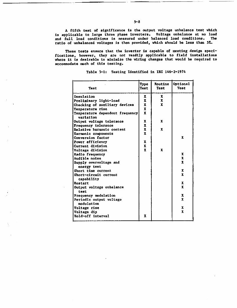
5-8
A fifth test of significance is the output voltage unbalance test whichis applicable to large three phase inverters. Voltage unbalance at no loadand full load conditions is measured under balanced load conditions. Theratio of unbalanced voltages is then provided, which should be less than 5x.
These tests ensure that the inverter is capable of meeting design speci-fications, however, they are not readily applicable to field installationswhere it is desirable to minimize the wiring changes that would be required toaccommodate much of this testing.
Table 5-1: Testing Identified in IEC 146-2-1974
Type Routine OptionalTest Test Test Test
Insulation X XPreliminary light-load X XChecking of auxiliary devices X XTemperature rise XTemperature dependent frequency X
variationOutput voltage tolerance X XFrequency tolerance XRelative harmonic content X XHarmonic components XConversion factor XPower efficiency XCurrent division XVoltage division X XRadio frequency XAudible noise ISupply overvoltage and X
energy testShort time current XShort-circuit current X
capabilityRestart XOutput voltage unbalance X
testFrequency modulation XPeriodic output voltage X
modulationVoltage rise XVoltage dip XHold-off interval I
5-9
IEEE P944, wCriteria for Application and Testing of Uninterruptible PowerSupplies for Power Generating Stations." (DRAFT)
This standard was prepared by the Working Group on Vital AC Power,Nuclear Power Subcommittee of the Power Generation Committee of IEEE. Whileapplicable to any generating station vital ac system, when combined with ap-plicable portions of IEEE 650-1979, this standard is intended to provide ap-plication and testing information pertinent to nuclear power plant inverters.Application requirements for battery chargers are not included.
Although this standard reiterates some of the performance requirementsdescribed in the standards previously discussed, it also addresses areas notmentioned or thoroughly covered by them. It is important that these be high-lighted here keeping In mind that this Is a draft standard which could changebefore final publication.
* The first area is providing guidance for transfer switch perfor-mance. Since transfer switches exist in a large number of plants,it is important that acceptable limits be established. This stand-ard recommends a maximum of 4.19 milliseconds (1/4 cycle) interrup-tion in the power supply as the load is transferred from the inver-ter output to the bypass source or vice-versa. This minor interrup-tion would have no effect on the supplied equipment.
* Addressing inverter sizing, the standard cautions that since the in-verter has very little long term overload capability, and it is 'notpractical or economically sound" to size the inverter to handle in-rush or short circuit current requirements, a solid state transferswitch should be used to compensate for the lack of capability. Asan alternative, fault clearing devices on selected high inrush loadsare recommended. In addition, it is recommended that loads bedivided into many branch circuits with high speed fuses or breakerson each. This would minimize fault clearing times and minimizesystem disturbances.
• A number of plants use maintenance bypass switches to supply thevital bus loads when maintenance is being performed on the inverter.The standard recommends use of a "make-before-break" type switchwhen load interruption is undesirable.
* This standard provides guidance on the quality of the ac alternatesupply, including the following:
- ± 10 Z voltage variation and + 1/2 % frequency regulation,
- a total harmonic distortion of 10 % shall not be exceeded,
- voltage surges shall not exceed the nominal value by more than20% and shall not last for more than 30 seconds,
- voltage impulses shall not exceed 6 W,
- overcurrent impulses shall not exceed 3000 amps.
5-10
Inverter testing recommended by this standard includes the designand routine tests listed in Table 5-1 as well as several of theoptional tests including short time current, short circuitcapability, restart, and output voltage imbalance.
Other industry standards indirectly relevant to battery chargers and/orinverters are also listed. These standards provide general backgroundinformation only, except as indicated.
* IEEE 308-1980, "Criteria for Class 1E Power Systems for NuclearPower Generating Stations." This standard requires that eachbattery charger have sufficient capacity to restore the battery fromthe design minimum charge to its fully charged state while supplyingnormal and post accident steady state loads.
* IEEE 323-1974, 'Qualifying Class IE Equipment for Nuclear PowerGenerating Stations."
* IEEE 336-1980, "Installation, Inspection, and Testing Requirementfor Class 1E Instrumentation and Electric Equipment at Nuclear PowerGenerating Stations.'
* IEEE 338-1977, 'Standard Criteria for the Periodic Testing ofNuclear Power Generating Station Class 1E Power and ProtectionSystems.'
IEEE 344-1975, 'Recommended Practices for Seismic Qualification ofClass 1E Equipment for Nuclear Power Generating Stations."
• IEEE 379-1977, "Standard Application of the Single Failure Criterionto Nuclear Power Generating Station Class lE Systems."
* IEEE 381-1977, "Standard Criteria for Type Tests of Class 1 ModulesUsed in Nuclear Power Generating Stations."
IEEE 384-1981, "Standard Criteria for Independence of Class 1EEquipment and Circuits."
IEEE 420-1982, "Standard for the Design and Qualification of ClassIE Control Boards, Panels and Racks Used in Nuclear Power GeneratingStations."
IEEE 450-1980, "Recommended Practice for Large Lead StorageBatteries for Generating Stations and Substations."
IEEE 484-1981, "Recommended Practice for Installation Design andInstallation of Large Lead Storage Batteries for Generating Stationsand Substations."
The industry has produced additional standards which relate to batterycharger and inverter subcomponents including:
5-11
* IEEE 107-1964, Standard for Rating and Testing Magnetic Amplifiers
* IEEE 449-1984, -IEEE Standard for Ferroresonant Voltage Regulators.Of interest in this standard is the statement that a "ferroresonantregulator, when specially designed and followed by rectifiers,provides an ideal battery charger..." Consisting of only theferroresonant transformer and the capacitor, the basic ferroresonantregulator requires no maintenance according to the standard.
* ANSI/IEEE C62.41-1980, -IEEE Guide for Surge Voltages in Low VoltageAC Power Circuits". Semiconductor sensitivity to the timing andpolarity of a surge varies significantly according to evidence pre-sented in this standard. Therefore, when performing surge testing,it is Important to test various conducting points. The standardalso points out that switching transients can result from fast act-ing current limiting fuses which leave trapped inductive energy inthe upstream circuit. Upon collapse of the field, high voltages aregenerated which could cause other damage.
* ANSI/IEEE Std. 428-1981, "IEEE Standard Definitions and Requirementsfor Thyristor AC Power Controllers".
* ANSI/IEEE C57.12-1978, 'IEEE Standard Requirements for InstrumentTransformers."
* IEEE Std.259-1974 (Reaffirmed 1980), "IEEE Standard Test Procedurefor Evaluation of Systems of Insulation for Speciality Trans-formers".
* IEEE Std. 392-1976, "IEEE Recommended Practice for Achieving HighReliability in Electronics Transformers and Inductors".
In the manufacture of magnetic components, many manual operationsare involved, and human errors are more likely than in an automatedoperation. Careful in-process inspection is the most effectivemeans of eliminating problems. For many electrical components suchas semiconductors and capacitors, burn-In is recommended toeliminate substandard parts.
This standard also recognizes that aging takes place In magneticcomponents. It discusses the validity and shortcomings of testingfor the effects of aging. The recommendations of this standard willbe further investigated during the phase 2 portion of the NPARProgram, which will include charger and inverter testing.
A number of regulatory guides were also reviewed to ascertain inverter/battery charger applications. These guides are vital to interpreting GeneralDesign Criterion 17 (GDC-17) 'Electric Power Systems" of IOCFR Part 50 whichstates, among other things, that "the on-site electric power supplies, includ-ing the batteries, and the onsite electric distribution system, shall havesufficient independence, redundancy, and testability to perform their safetyfunctions assuming a single failure."
5-12
Regulatory Guide 1.32 'Criteria for Safety Related Electric Power Systemsfor Nuclear Power Plants' generally endorses IEEE 308-1974 with several excep-tions Including one related to battery charger capacity. The Regulatory Guideindicates that the battery charger should be capable of restoring the batteryfrom a minimum charge to a fully charged state while supplying the largestcombined demands of the various loads-not limited to normal or post accidentconditions. A second Important exception taken to the IEEE standard 308-1974is in the configuration area. The Regulatory Guide specifically considerssharing of dc power among units at a multi-unit site to be unacceptable.
Safety Guide 6 and Regulatory Guide 1.6 discuss the required independencebetween redundant standby (onsite) power sources and their distribution sys-tems. Again, as in Regulatory Guide 1.32, the emphasis is to ensure thatpostulated single failures do not disable redundant sources. Specifically,this means that automatic paralleling of two sources is not permitted, nothrowover of loads from one safety bus to another should exist, and interlocksshould be provided to prevent an operator error that would parallel thesources.
Regulatory Guide 1.93 entitled "Availability of Electric Power Sources"discusses the operating aspects of a loss of an offsite or onsite power sourceIncluding dc supplies. The intent to implement the safest operating modewhenever the available sources are less than the. Limiting Conditions for Oper-ation (LCO) is described in detail, including the possibility of maintaining apower condition versus proceeding to a shutdown condition when the number ofavailable sources are less than the LCO.
Regulatory Guide 1.75, "Physical Independence of Electric Systems" dis-cusses the physical independence of electric equipment associated with classlE systems and 'auxiliary or supporting systems" (battery chargers and inver-ters) which must be operable for systems to perform their safety related func-tions. This Regulatory Guide generally endorses IEEE standard 384-1974,however, It includes more than a dozen changes or clarifications to thatstandard.
5.3 Technical Specifications
Nuclear plant technical specifications (tech specs) for battery chargersand inverters vary from plant-to-plant because of different bus configura-tions, the varied safety impact of equipment failure, and plant age (minimalcharger/inverter tech spec requirements exist for some older plants). Thestandard technical specifications for each type of commercial reactor (GE,Westinghouse, C-E, B&W) were reviewed and found to contain similar require-ments for chargers and inverters. The G.E. BWR Technical Specification, asfound In NUREG-0123, 'Standard Technical Specifications for General ElectricBoiling Water Reactors" requires restoration of an inoperable vital ac bus(inverter) within 8 hours or the plant must be placed in hot shutdown in thenext 12 hours and cold shutdown in the following 24. The Standard Tech Specassumes four 120 volt ac vital buses, but does not indicate a different LCO ifthere are different numbers of vital buses, automatic throw-over capability,or an alternate supply. Similarly for PMRs, the standard tech specs [29-311
5-13
indicate that if a vital ac bus is inoperable for 8 hours the plant should beplaced in the hot standby mode in the next 6 hours and cold shutdown in thefollowing 30 hours. This LCO is identical for the Westinghouse, C-E, and B&Wstandard tech specs.
Other selected PWR technical specifications revealed more stringent re-quirements including requiring bus restoration within 2 hours and proceedingto a hot standby status in the next 6 hours. Selected BWR technical specifi-cations revealed no LCO for inverters.
For battery chargers, the standard technical specifications for BWRsrequires restoration of an inoperable dc bus, charger, or battery within 2hours or the plant has to be placed in a hot shutdown condition in the next 12hours and cold shutdown in the following 24 hours. PWRs are similar exceptthat if the charger is inoperable for 2 hours, the plant must be placed in hotstandby in the next 6 hours and cold shutdown in the following 30 hours.Again, individual tech specs vary and include more relaxed restrictions thanoffered by the standard tech specs including the following:
At a BWR with two dc buses, a charger that Is inoperable in onedivision must be restored within seven days or the plant mustproceed to a shutdown condition.
* At a PWR with two chargers per battery, operation can continue Inde-finitely with one charger inoperable in each battery division.
5,4 Manufacturer Recommendations
A review of battery charger and inverter manufacturer maintenance recom-mendations can be summarized by the general philosophy of keeping theequipment clean while periodically checking the tightness of wiring connec-tions and replacing parts indicated in the qualification report to be age sen-sitive. More specific recommendations include the following. Unless specificto only one type of inverter or charger, it may be assumed that these recom-mendations could apply to both battery chargers and inverters.
* Oil filled and electrolytic capacitors should be replaced everyseven years (some manufacturers recommend every four years, someevery 10 years).
• The fans in large units with forced air cooling should be replacedevery two years.
• Air filter should be cleaned.
* Monthly inspection should be made for evidence of overheating.
* Terminal connection tightness should be checked quarterly.
* The inside of the units should be cleaned (vacuumed) quarterly.
* Voltages should be measured quarterly.
5-14
* For extended storage before installation and prolonged idleperiods after installation, equipment should be covered with plasticto protect against dust and moisture.
* Wiring connections should be soldered - the use of push on type con-nectors should be minimized.
* The rectifier assembly should be cleaned periodically to preventthese parts from running at too high a temperature.
* The ferroresonant inverter should not be operated at no load forlonger than 72 hours to prevent overheating due to high losses inthe regulating transformer.
* For optimum regulation of a ferroresonant inverter, the invertershould be loaded between two thirds full load and full load.
* Dust and dirt should be wiped from heat sink surfaces using a cleanlint-free cloth dampened with carbon tetrachloride. (Note: restric-tions on the use of carbon tetrachloride may make it unacceptablefor use in a nuclear power station.)
* Open relay contact points and terminal posts should be inspected andcleaned with a clean lint-free cloth dampened with carbon tetra-chloride. Burnish contact points if required.
* Terminal connections should be torqued tight annually especiallyhigh current conductor connectors.
5.5 NRC Experience, Expert Knowledge, and On-Going Research
Present NRC interest in vital ac power, of which the inverter is an inte-gral part, is documented in Issue No. 48, LCO for Class 1E Vital InstrumentBuses in Operating Rectors. Research [181 on this issue has resulted in re-commendations such as the implementation of a 72 hour annual time limitationfor energizing a vital ac bus from an interruptible power source, i.e., an al-ternate bus. Other potential recommendations include the standardization oftechnical specifications for vital ac buses, and the definition of minimumplant configuration requirements.
The Office for Analysis and Evaluation of Operational Data (AEOD) hascontinued to follow inverter performance and has found unsatisfactory im-provement in failure rates and failure consequences despite substantial regu-latory and industry recommendations/requirements in this area. Transients,including reactor trips and safety injections, continue to occur because ofinverter failure or vital bus degradation. In addition, because of thepotential for a significant plant impact when an inverter fails, a second NRCgroup studying issue A-17, "System Interaction," has also initiated researchinto inverter performance on the systems level. This includes a review ofsignificant instrumentation which is powered by the vital bus and the effectof its loss on operator performance during a severe transient event.
5-15
Similarly, in the area of de power of which the battery charger is an in-tegral part, the NRC has studied, and continues to research, the performanceof safety related de power supplies and the impact that a loss of de has onplant safety.
In July 1977, the NRC issued a report [321 which addressed the reli-ability of dc power supplies at operating nuclear power stations, and discus-sed the likelihood and the consequences of a postulated failure of all dc dur-ing normal operation of a plant. The NRC staff concluded that because of theimportance of ac and dc power systems, efforts to review the reliability ofthese systems should continue.
In April 1981, a second study of dc power was performed by the NRC [331as part of the work on Issue A-30, 'Adequacy of Safety Related DC Power Sup-plies." The issue here is primarily one of dc independence to minimize thepotential for common mode failure. This study was a probabilistic safety as-sessment to determine the relative contribution of dc power related accidentsequences to the total core damage probability. A significant finding of thisPRA study was that a -potentially large contribution could be reduced byrequiring dc power divisional independence, and improved test, maintenance,and surveillance of dc components, including batteries and chargers.
A paper [341 summarizing EPRI research in the qualification of safetyrelated electrical equipment describes ongoing work devoted to improvingequipment qualification technology including the comparison of aging techni-ques by comparing naturally and artificially aged devices, and to the develop-ment of a better understanding of the relationship between reliability andqualification.
After extensive testing on the seismic-aging correlation of electricalequipment, EPRI has concluded that certain components such as resistors, capa-citors, diodes, and terminal blocks have no seismic-aging correlation andshould be exempted from the requirement to age condition (thermally and oper-ationally) before seismic testing. Studies continue in this area on addi-tional component types.
In conjunction with the EPRI work, Gleason [351 further described thetesting performed on electrical and electronic components typically located inmild environments. Describing the dominant aging mechanisms as thermal, radi-ation and operational cycling, the author proceeds to discuss the seismic per-formance of components that have been aged. This paper indicates that relaysare being further evaluated as well as other safety related equipment, includ-ing naturally aged equipment.
A study 1271 to evaluate the aging of electronic components such as semi-conductors, capacitors, and resistors used in safety related instrumentation,particularly those used in harsh environments, revealed the following:
* Resistors are stable components, however, different 'types of resis-tors should be subjected to aging factors such as humidity and vi-bration to determine their total aging characteristics in a plantenvironment.
C
5-16
* Capacitors need further study to understand potential failuremechanisms and to determine the need for voltage endurance testing.
* Semiconductors and integrated circuits are environmentally and oper-ationally sensitive components. New semiconductor technologies needto be reviewed since it should not be assumed that improvements aredirectly applicable to nuclear power plants.
Further work recommended includes investigation of the importance ofhumidity in accelerated aging, and identification of the factors unique to thenuclear plant environment and operation, and of other electronic componentsused both inside and outside containment.
A study [36] investigating the use of solid state motor controllers innuclear power plants describes the performance of devices similar to control-lers, namely battery chargers and inverters. Equipment qualification reportsfor nuclear chargers and inverters were reviewed. The authors noted thatsemiconductors and resistors were analyzed for margin of safety by evaluatingthe ratio of actual power divided by rated power. This "stress ratio" is de-fined as (applied power)+(rated power) for semiconductors, integrated cir-cuits, resistors, transformers, terminal blocks, and connectors, and as (ap-plied voltage)+(rated voltage) for capacitors.
In this analysis every component's stress ratio is determined (2686 indi-vidual components in this particular inverter) requiring a detailed circuitanalysis to determine the electrical conditions applied at each component.
Many documents dealing with electronic component reliability and qualifi-cation address research performed by the military 1371. In some cases, thecomponent military applications can be compared to nuclear plant use in theareas of temperature, humidity, seismic, and radiation. Guidance expressed inthe referenced document indicates that electronics applications suffer fromunreliability sometimes due to the recognized fact that the electronics art is"often in revolution."
Because inverters and battery chargers are located In mild environments,particular attention was paid to studies discussing electrical equipment qual-ification. One such paper 1351 concluded that it is possible to demonstratethat "complex electronic equipment will perform its safety related function ina mild environment for 40 years without any common mode failures caused byaging." The methodology to do this was a combination of analysis and typetesting.
As demonstrated by the number of standards and publications, it is clearthat battery chargers and inverters and their subcomponents have been exten-sively studied. The continuing work in the systems interaction area isextremely important and, as illustrated in Section 4 of this report, isobviously warranted. In addition, the expanding influence that electroniccomponents have on nuclear industry equipment performance makes it necessaryfor the industry to develop and/or modify existing standards to ensure thatexpected reliability levels are achieved.
5-17
From the review of manufacturer recommendations, user specifications, in-dustry standards, and regulatory guidance, it is evident that the mechanismsare in place to incorporate additional or different testing, monitoring, and/or preventive maintenance measures to improve equipment and system perfor-mance.
6-1
6.0 CONCLUSIONS AND RECOMMENDATIONS
Inverters and battery chargers used in nuclear power plants perform sig-nIficant functions related to plant safety and availability. The specific Im-pact of a battery charger or Inverter failure varies with plant configuration.Operating experience data have demonstrated that reactor trips, safety injec-tion system actuations, and inoperable emergency core cooling systems have re-sulted from Inverter failures; and de bus degradation leading to diesel gener-ator inoperability or loss of control room annunciation and indication haveresulted from battery and battery charger failures. For the battery chargerand the inverter, the aging and service wear of subcomponents have contributedsignificantly to the history of equipment failure.
To identify and characterize aging and service wear effects which couldcause battery charger or inverter degradation and thereby impair plant safety,a study has been completed of the battery charger and Inverter designs employ-ed in nuclear power stations, the configuration and alignment of this equip-ment within the plant's electrical scheme, the identification of subcomponentfailures, and the effects that charger or inverter failures,especially thoserelated to aging, have had or could have on plant performance and safety. Inthis report, actual nuclear power plant operating experiences are cited insupport of a number of conclusions regarding the design, fabrication, opera-tion., application, and maintenance of battery chargers and inverters. In ad-dition, several interim recommendations are made with regard to the inspec-tion, surveillance, and monitoring of battery chargers and inverters, as wellas maintenance practices which may be effective In mitigating aging effects.Further analyses of the equipment operating characteristics coupled with thetesting of naturally aged equipment are expected to result In maintenance and/or testing techniques which are not only technically feasible, but are practi-cal as well.
6.1 Conclusions
6.1.1 Design and Fabrication
Sections 2 and 3 addressed the basic principles of operation of the threetypes of battery chargers and the four types of inverters used in nuclearpower stations, and described the major subcomponents which make up thisequipment along with some of the environmental and operational factors thataffect their performance.
Perhaps the most significant problem related to the aging and servicewear of components Is the limited life of the electrolytic and oil filledcapacitors used in every type of charger and Inverter. On the basis of thepoor operating experience identified by the data, and the documented relation-ship of capacitor life to applied voltage and ambient temperature, It may beconcluded that use of capacitors with higher voltage and temperature ratingswould increase capacitor life and therefore Improve equipment performance. Itshould be noted that an inverter design such as the PWM type, which requiressmaller filter capacitors because of the higher frequency harmonics associatedwith the output waveform, may not be as susceptible to the capacitor failuresexperienced by other types.
6-2
Other design or fabrication related conclusions reached include the fol-lowing:
- Battery charger and inverter subcomponents are susceptible to damagefrom electrical transients. Surge suppression schemes on the inputto the equipment have been effective in minimizing this concern,especially when used to protect the SCRs in the rectifier circuit.
- From the number of component failures attributed to overheating, itis concluded that reliance on convection cooling principles is in-adequate for certain designs and installations. Filtered forced aircooling is generally available as an option.
- Zener diodes can change characteristics with time because of impuri-ties introduced during the manufacturing process.
- Transformer insulation rating is an important attribute for extend-ing the service life of this key component. Recent upgrades byseveral utilities to higher temperature Insulation ratings leads tothe conclusion that equipment Internal temperatures are higher thananticipated, and materials, especially insulating materials used inolder equipment, are not at present day standards, I.e., class Bversus class H insulation.
- Battery charger failures at certain plants are not detected untilthe dc bus voltage has decreased to the point that an alarm is ob-tained. The battery life at that time has been sufficiently short-ened that the battery would be unable to supply the required dcloads for the time period specified in the plant design documents(FSAR).
6.1.2 System Interactions
The operating experience data have revealed the significant impact thatthe loss of a vital ac or dc bus can have on plant safety and availability.Reactor trips, safety injection system actuations, emergency core cooling sys-tem inoperability, and loss of decay heat removal capability are some of theconsequences of inverter and battery charger failures. Although most of thesignificant plant transients have been the result of inverter failures, it hasbeen demonstrated that the inverter and the battery charger are closelycoupled in nuclear plant applications, contain identical components, and aresubjected to similar stresses.
From the information presented in Section 4, it is concluded that batterycharger and inverter failures at many plants directly affect reactor safety.As cited by the NPRDS 1983 annual report, the inverter is the component withthe highest failure contribution in both the Reactor Protection Systems andthe Emergency Core Cooling Systems (ECCS) for PWRs and BWRs. Battery chargers(and batteries) rank third as a contributor to ECCS failures. The bus config-uration, specifically the existence of a standby or redundant full capacitybattery charger for dc systems, or an automatic throwover switch to an emer-gency ac regulated supply for vital ac systems, is a significant factor in
6-3
assessing the consequences of equipment failure and will determine how systemsare impacted. The loads being supplied by each bus are plant specific andwill also determine plant response to a loss of vital ac or dc event. Ingeneral, however, the data confirm that plant safety system operation andavailability are directly affected by inverter and charger performance, andtherefore this equipment warrants considerable attention.
Other conclusions developed as far as plant operation and system inter-actions are concerned Include the following:
- Emergency diesel generator testing requirements could result instresses being placed on chargers and inverters because of the widefrequency and voltage variations permitted by the diesel output.This is particularly evident in ferroresonant type Inverters wherephase unbalances can cause circulating currents within the transfor-mer, which produces heat and accelerates component failures.
- Addition of a standby charger or a second full capacity charger on adc bus dramatically reduces the number of LERs associated with bat-tery charger failures, which implies an increased reliability formaintaining the batteries in a fully charged condition.
- Inverter performance is best on those units that employ a manualtransfer switch, but no rectifier. The small number of plantsincluded in the survey with automatic throwover switch capabilitymake conclusions on this mode of operation difficult. Manufacturersreport that the use of an automatic throwover scheme offers thehighest system reliability and is typically required in military andcomputer industry applications.
6.1.3 Aging and Service Wear Characteristics
Perhaps the major goal of the research performed was to identify problemsexperienced (or which may be experienced) by inverters and battery chargerswhich are related to aging and service wear. This portion of the study con-centrated on component level failure analysis including a close look at fail-ure causes. As revealed by WPRDS data, the utilities considered at least 30%of the inverter and charger failures to be age related. Thus, mitigation ofthe effects of aging can significantly improve equipment performance. Theaging and service wear characteristics identified in this report include thefollowing:
- Increases in ambient or Internal temperatures can have a dramaticeffect on inverter and charger performance. Overheating is a majorcontributor to aging related failures and was especially noticeablein failures of capacitors, transformers, and semiconductors. Seeinterim recommendations (Section 6.2) for possible improvementsin this area.
- A number of weak links have been identified which could cause an in-verter or battery charger, when aged, to fail under seismic loads.These include cabinet mountings, circuit board supports, wire andcable connectors, relays and circuit breakers, and oil filled capa-citors.
6-4
- Chargers and inverters have a "wear out period" after four to sixyears of operation. That is, the failures, when plotted against theplant age at the time of failure (Figure 4-1), produced a curve sim-ilar to the classic bathtub curve with the wear out region occurringbetween years four and six.
6.1.4 Industry and Regulatory Criteria
Perhaps the most significant conclusions realized in the area of industryand regulatory recommendations is In the testing area. While much of the re-commended industry testing deals with the manufacturing end of the business,sufficient inference to continued testing exists to conclude that periodic in-verter and battery charger testing is not only desirable but necessary. Real-izing that some of the industry standards reviewed were not solely dedicatedto nuclear applications, the type of testing specified which would be relatedto ensuring the safety related application of Inverters and chargers, is inthe nature of capacity testing. Although some plants are required to performperiodic capacity tests of their battery chargers, this requirement is notuniversal. Evidence of required inverter capacity testing was not indicated.
Additional conclusions in this area include the following:
- The number of failures whose causes are unknown lead us to concludethat investigations following an equipment failure are inadequate.This may be due to either equipment unfamiliarity or timeconstraints. Because of the potential impact on plant safety andavailability, this approach is not justifiable.
- Personnel errors in the design, manufacture, operation, and mainte-nance of battery chargers and inverters account for a large percen-tage of documented failures (-15%). It may be concluded that im-provements in maintenance and operating personnel training would tar-prove overall performance levels considerably.
- Classification of inverters as safety related equipment is not con-sistent, as evidenced by a review of 15 BWRs which have Inverterssupplying their vital bus but do not consider this equipment to besafety related. Since the inverter failures at these plants couldaffect safety system operation, it is concluded that this equipmentshould be reclassified.
6.2 Interim Recommendations
On the basis of a detailed review and analysis of operating experiencesas provided by a number of varied data sources including LER9, NPRDS, IPRDS,NPE, and plant maintenance records, and supplemented by information fromvendor instruction manuals and industry standards, a number of interimrecommendations are made which may improve battery charger and inverterreliability and thereby increase the performance level of nuclear safetysystems. Further research into these recommendations will be completed aspart of the Phase 2 study which will evaluate the cost/benefit value and thepractical applicability.
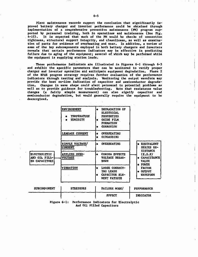
6-5
Plant maintenance records support the conclusion that significantly im-proved battery charger and inverter performance could be obtained throughimplementation of a comprehensive preventive maintenance (PM) program sup-ported by personnel training, both in operations and maintenance (See Fig.4-15). It is expected that much of the PM would be checks of connectiontightness, structural support Integrity, and cleanliness, as well as examina-tion of parts for evidence of overheating and wear. In addition, a review ofsome of the key subcomponents employed in both battery chargers and invertersreveals that certain performance Indicators may be effective in predictingfailure due to aging of the equipment; several of which may be performed whilethe equipment is supplying station loads.
These performance indicators are illustrated in Figures 6-1 through 6-3and exhibit the specific parameters that can be monitored to verify propercharger and inverter operation and anticipate equipment degradation. Phase 2of the NPAR program strategy requires further evaluation of the performanceindicators through testing and analysis. Monitoring the output waveform mayprovide the best on-line indication of capacitor and semiconductor degrada-tion. Changes in wave shape could alert personnel to potential problems aswell as to provide guidance-for troubleshooting. Note that resistance valuechanges (a fairly simple measurement) can also signify capacitor andsemiconductor degradation, but would generally require the equipment to bedeenergized.
ENVIRONMENT . DEGRADATION OF.ELECTRICAL
* TEMPERATURE PROPERTIES* HUMIDITY * OXIDE FILM
FORMATION* CORROSION
LEAKAGE CURRENT * OVERHEATING* OUTGASSING
RIPPLE VOLTAGEI * OVERHEATINGCURRENT
APPLIED OVER- * CORONA EFFECTSVOLTAGE VOLTAGE BREAK-
DOWN
VIBRATION * LOOSE CONNECT-ING LEADS
* CAPACITOR ELE-MENT FATIGUE
ELECTROLYTICAND OIL FILL-ED CAPACITORS
* EQUIVALENTSERIES RE-SISTANCE(E.S.R)
* CAPACITANCEVALUE
* POWERFACTOR
* OUTPUTWAVEFORM
SUBCOMPONENT STRESSORS FAILURE MODE/ PERFORMANCE*1 I
EFFECT INDICATOR
Figure 6-1: Performance Indicators for ElectrolyticAnd Oil Filled Capacitors
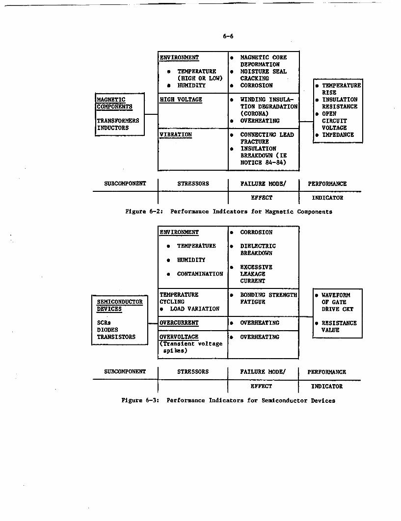
6-6
MAGNETICCOMPONENTS
TRANSFORMERSINDUCTORS
ENVIRONMENT * MAGNETIC COREDEFORMATION
* TEMPERATURE * MOISTURE SEAL(HIGH OR LOW) CRACKING
* HUMIDITY * CORROSION
HIGH VOLTAGE * WINDING INSULA-TION DEGRADATION(CORONA)
* OVERHEATING
VIBRATION * CONNECTING LEADFRACTURE
* INSULATIONBREAKDOWN (IENOTICE 84-84)
* TEMPERATURERISE
* INSULATIONRESISTANCE
* OPENCIRCUITVOLTAGE
* IMPEDANCE
SUBCOMPONENT STRESSORS FAILURE MODE/ PERFORMANCE4 4 1
EFFECT
Indicators for Magnetic
I INDICATOR
ComponentsFigure 6-2: Performance
ENVIRONMENT * CORROSION
* TEMPERATURE * DIELECTRICBREAKDOWN
* HUMIDITY* EXCESSIVE
* CONTAMINATION LEAKAGECURRENT
SEMICONDUCTORDEVICES
SCRSDIODESTRANSISTORS
TEMPERATURECYCLING* LOAD VARIATION
* BONDING STRENGTHFATIGUE
* WAVEFORMOF GATEDRIVE CKT
* RESISTANCEVALUE
4
OVERCURRENT * OVERHEATING
OVERVOLTAGE * OVERHEATING(Transient voltagespikes)
SUBCOMPONENT STRESSORS FAILURE MODE/ PERFORMANCEI I I
EFFECT INDICATOR
Figure 6-3: Performance Indicators for Semiconductor Devices
6-7
Other interim recommendations which will be pursued in Phase II includethe following:
- Because of the obvious detrimental impact of high ambient and Inter-nal temperatures, forced air cooling of certain sized units may bewarranted. Convection cooling is typically used in units up to 50KVA.
- Additional attention to inverters and battery chargers is requiredduring the final plant construction phase and initial plant opera-tion to minimize stresses on the equipment that could accelerateaging and cause premature failures. This includes frequent inspec-tion for cleanliness during construction and additional protectionfor the equipment (I.e., surge suppression) during startup testing.
- Each plant is unique in its bus configuration and load distribution.Despite redundancies of supply, however, inverter and charger fail-ures can result in extensive plant interactions. Procedures shouldbe in place at each plant to respond to charger and inverter fail-ures as far as total plant response is concerned. Alerting opera-tors to safety system operational changes or instrument indicationunreliability is an important feature of the procedures.
- The operation of fast acting fuses typically used in batterychargers and inverters has resulted in a large number of inverterand battery charger failures. While designed to protect sensitivesubcomponents from damage due to electrical transients which fre-quently occur in a power plant environment, indication of fuse fail-ures due to thermal fatigue makes it necessary to pursue this fail-ure mechanism in a future study. Because of the extensive applica-tion of fuses throughout the power plant, fuse failures due to agingcould have a dramatic impact on plant safety system operations.
- For components such as capacitors and transformers, actual operatingdata support equipment qualification recommendations obtainedthrough artificial aging techniques or analyses as specified in IEEE650-1979. Adherence to the manufacturer's equipment qualificationrecommendations should be enforced in these cases, even though theequipment is located in a mild environment (IOCFR50.49 currentlyexcludes equipment located in mild environments).
- Periodic capacity testing of chargers and Inverters should be con-ducted to ensure the capability of this equipment to supply requiredloads for the required times. In conjunction with the above test-ing, this work should be performed to verify the failure mechanismsthat would permit equipment operation under normal conditions, butwould cause equipment failure when maximum rated conditions wereapplied.
6-8
6.3 Future Work
To determine the effectiveness of the recommendations presented, future
work will be conducted consisting of a combination of testing and analyses.
The testing area will include work with naturally aged battery chargers and
inverters obtained from the Shippingport facility and will consist of monitor-
ing the equipment under various conditions, including the application of
seismic forces.
To achieve the goal of developing a cost effective preventive maintenanceprogram, additional efforts will be focused on a cost/benefit evaluation for
various inspection, surveillance, and monitoring techniques that are employed
or that are developed through continued study. In addition to preventive
maintenance recommendations, information on standards and regulation will beput into final form and technically justified.
7-1
7.0 REFERENCES
1. Murphy, C., -operating Experience Review of Aging Information forBatteries, Chargers, and Inverters," ORNL Letter Report, May 1984.
2. Bozold, G.E. and Papazoglou, I.A., "Analysis of Inverter Failures inNuclear Power Plants," ENL Technical Report, April 1983.
3. Bhatti, J.S., "Investigation of Failures in I&E Power Supply Hardware,"NSAC-44, December 1981.
4. Vora, J.P., "Nuclear Plant Aging Research (NPAR) Program Plan," USNRCNUREG-1144, July 1985.
5. "Standard for Qualifying Class IE Equipment for Nuclear Power GeneratingStation," IEEE 323-1974. Available from IEEE, 345 East 47th Street, NewYork, NY 10017.
6. "IEEE Standard for Qualification of Generating Stations," IEEE 650-1979.Available from IEEE, 345 East 47th Street, New York, NY 10017.
7. Pink, D.G. and Beaty, H.W., "Standard Handbook for Electrical Engineers,"McGraw-Hill Book Company, 1979.
8. Fink, G.D., "Electronics Engineers' Handbook," McGraw-Hill Book Company,1975.
9. Frost-Smith, E.H., "The Theory and Design of Magnetic Amplifiers,"Chapman & Hall, Ltd., 1953.
10. Yearsin, J.J., "Advantages of Ferroresonant Inverters," SolidstateControls, Inc.
11. Bedford, B.D. and Hoft, R.G., 'Principles of Inverter Circuits," JohnWiley & Sons, 1964.
12. Yohman, E.J., "Static Inverters for Uninterruptible AC Power Systems,"Cyberex, Inc. Publication T-30901.
13. Jowett, E.C., "Reliability of Electronic Components," Iliffe Books Ltd.,1966.
14. McManus, Ronald. P., "Capacitor Reliability In Switched Mode Power SupplyDesign," Sprague Electric Co. Technical Report No. TP 79-3, May 1979.
15. Ott, Henry W., "Noise Reduction Techniques in Electronic Systems," JohnWiley & Sons, 1976.
16. Revland, W. and Wyckoff, H., "Workshop on Vital DC Power," NSAC-48, March1982.
7-2
17. Youngblood, R., et al., "Fault Tree Application to the Study of SystemInteractions at Indian Point 3," NUREG/CR-4207, BNL-NUREG - 51872,Brookhaven National Laboratory, January 1986.
18. St.Leger-Barter, Gerald, "Technical Evaluation Report on the 120 VACVital Instrument Buses and Inverter Technical Specificatins Issue l71,"Lawrence Livermore Laboratory Report No. VC1D-19469, October 1982.
19. Brown, S.R. and Trojovsky, M., "Data Summaries of Licensee Event Reportsof Inverters at U.S. Commercial Nuclear Power Plants, 1/1/76 to 12/31/82,NUREG/CR-3867, EG&G Idaho, Auguts 1984.
20. Sugarman, A.C., "Aging-Seismic Correlation Study on Class 1E Equipment,"NUREG/CR-3808, June 1984.
21. Gleason, J.F., "Correlation Betwen Aging and Seismic Qualification forNuclear Plant Electrical Components," EPRI NP 3326, December 1983.
22. Yanev, P.I. and Swan, S.W., "Pilot Program Report: Program for theDevelopment of an Alternative Approach to Seismic EquipmentQualificatin,' Vol. I and II., EQE Inc. Reports, 1984.
23. Brown, S.R. and Trojovsky, M., "Quick Look at Licensee Event Reports ofBatteries and Battery Chargers at U.S. Commercial Nuclear Power Plants;January 1, 1976 to December 31, 1981. EG&G Idaho Technical ReportEGG-EA-6074.
24. Kahl, W. and Borkowski, R.J., "The In-Plant Reliability Data Base forNuclear Plant Components: Interim Report-Diesel Generators, Batteries,Chargers, and Inverters," NUREG/CR-3831, Oak Ridge National Lab., January1985.
25. "Nuclear Power Experience," Published by the S.M. Stoller Corporation,several volumes for BWR and PWR systems.
26. Vinal, G.W., "Storage Batteries," John Wiley & Sons, 1955.
27. Johnson, R.T., et al., "A Survey of the State-of-the-Art in Aging ofElectronics with Application to Nuclear Power Plant Instrumentation,"NUREG/CR-3156, Sandia National Laboratories, April 1983.
28. "IEEE Standard Dictionary of Electrical and Electronic Terms," ANSI/IEEE100-1977. Available from IEEE, 345 East 47th Street, New York, NY10017.
29. U.S. Nuclear Regulatory Commission, "Standard Technical Specificatins forBabcock & Wilcox Pressurized Water Reactors," USNRC Report NUREG-0102,July 1979.
30. U.S. Nuclear Regulatory Commission, "Standard Technical Specificationsfor Combustion Engineering Pressurized Water Reactors," USNRC ReportNUREG-0212, Fall 1980.
31. 'Standard Technical Specifications for Combustion Engineering PressurizedWater Reactors, "Westinghouse Report, NUREG-0452.
7-3
32. U.S. Nuclear Regulatory Commission, "Technical Report on D.C. PowerSupplies in Nuclear Power Plants," USNRC NUREG-0305, July 1977.
33. U.S. Nucfear Regulatory Commission, "A Probabilistic Safety Analysis ofDC Power Supply Requirements for Nuclear Power Plants," USNRC NUREG-0666,
April 1981.
34. Sliter, G.E., "EPRI Research in Qualification of Safety RelatedElectrical Equipment," Vol. 24 of Nuclear Safety, July 1983.
35. Gleason, J.F., "Aging and Seismic Performance for Safety RelatedEquipment in a Mild Environment," Vol. No. 1, IEEE Transactions onNuclear Science,. January 1984.
36. Jaross, R.A., et al., "State of the Art of Solid State MotorControllers," Argonne National Laboratory, NUREG/CR-4180, September 1984.
37. U.S. Department of Defense, "Military handbook - Reliability Predictionof Electronic Equipment," MIL-HDBK-217D, April 1979.
38 Hofmayer, C.H. and Bandyopadhyay, K.K., "Proceedings of the Workshop onSeismic and Dynamic Fragility of Nuclear Power Plant Components,"NUREG/CR-0070; BNL-NUREG-51924.
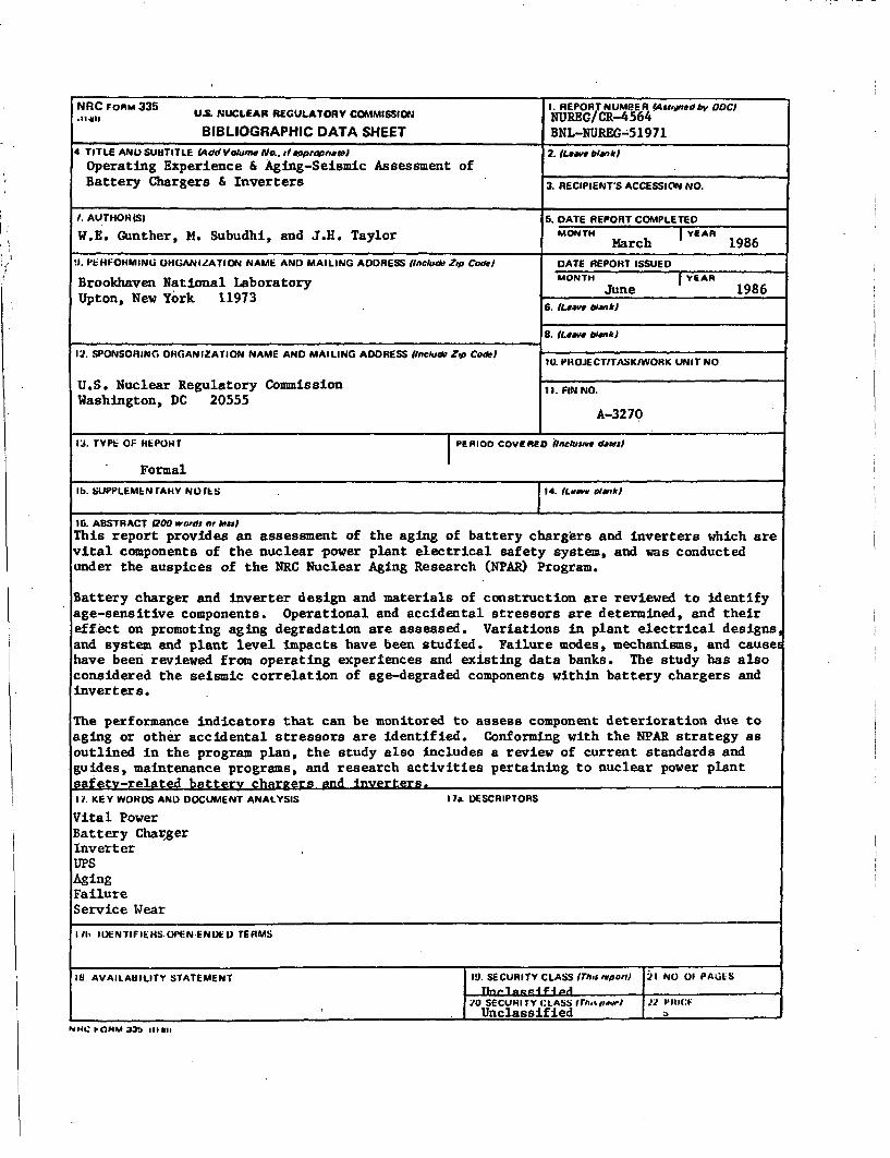
NRC FORM 335 1. REPORT N U~eER (4sstjoned by 0DCNRJICBM U. NUCLEAR REGULATORY COMMISSION NUREG/CR-4564
BIBLIOGRAPHIC DATA SHEET BNL-NUREG-519714 TITLE AND SUHTITLE (4dd Vo.Anw Noe, desppWpirew) 2. (Leave blankJ
Operating Experience & Aging-Seismic Assessment ofBattery Chargers & Inverters 3. RECIPIENTS ACCESSION N.
I. AUTHOR(S) 5. DATE REPORT COMPLETED
W.E. Gunther, M. Subudhi, and J.H. Taylor MONTH MArh YER 1986
V. PEHFOHMINU ORGANIZATION NAME AND MAILING ADDRESS fInclude Zip Codne DATE REPORT ISSUED
Brookhaven National Laboratory MONTH J YEAR 1986Upton, New York 11973 June9
6. Leave bianJr
8. (Le. blank)
12. SPONSORING ORGANIZATION NAME AND MAILING ADDRESS (Include Zip Code) 10. PHOJECT/TASK/WOHK UNIT NO,
U.S. Nuclear Regulatory Commission It. FINNO.Washington, DC 20555
A-3270
13. TYPE OF EPOHRT PERIOD COVERED Incluseve daWeJ
. Formal
1!b. SUPPLEMEN rAHY No rks . 4.{ate 014vo
1. ABSTRACT (200 wornds or Iess)This report provides an assessment of the aging of battery chargers and inverters which arevital components of the nuclear power plant electrical safety system, and was conductedunder the auspices of the NRC Nuclear Aging Research (NPAR) Program.
Battery charger and inverter design and materials of construction are reviewed to identifyage-sensitive components. Operational and accidental stressors are determined, and theireffect on promoting aging degradation are assessed. Variations in plant electrical designs,and system and plant level impacts have been studied. Failure modes, mechanisms, and causeshave been reviewed from operating experiences and existing data banks. The study has alsoconsidered the seismic correlation of age-degraded components within battery chargers andinverters.
The performance indicators that can be monitored to assess component deterioration due toaging or other accidental stressors are identified. Conforming with the NPAR strategy asoutlined in the program plan, the study also includes a review of current standards andguides, maintenance programs, and research activities pertaining to nuclear power plantsafety-related battery charters and inverters.I1. KEY WORDS AND DOCUMENT ANALYSIS 17a. DESCRIPTORS
Vital PowerBattery ChargerInverterUPSAgingFailureService Wear
1/11 II)ENTIFIEHS.OIEN-ENDEU TERMS
18 AVAILAeILITY STATEMENT IO SECURITY CLASS 1rhoseootf 21 NO OF PAGESTint-langifi4i
2d0 SECURITY CLASS rh-sp} w) P141(:FUnclassified
NNC IONM14 335 ,,",,i