Numerical study of super-critical carbon dioxide flow in...
13
The 6th International Supercritical CO2 Power Cycles Symposium March 27 - 29, 2018, Pittsburgh, Pennsylvania Numerical study of super-critical carbon dioxide flow in stepped- staggered labyrinth seals Yuming Zhu a,b , Yuyan Jiang a, *, Shiqiang Liang a , Yongxian Guo a , Chaohong Guo a , Peng Yue a a Institute of Engineering Thermophysics, Chinese Academy of Sciences b University of Chinese Academy of Sciences ABSTRACT In this paper, a new kind of axial labyrinth seals, called stepped-staggered labyrinth seals, has been described to reduce process gas escaping from the shaft end of SCO2 compressor, and numerical study of super-critical carbon dioxide flow(SCO2) has been applied to evaluate its performance compared to see-through labyrinth. The computational fluid dynamic(CFD) calculations were carried out using the NUMECA commercial code. To minimize the computational cost and keep the desired level of accuracy in the characterization, the NIST REFPROP database was used for the computation of SCO2 in the numerical investigation. It can be observed that throttling effect exists in both seal clearance and shoulder clearance, and strong vortex flow occurs at staggered cavity. So, the Stepped-staggered labyrinth seals have better seal performance than see-through labyrinth and avoid the assembly problem of axial interlocking labyrinth. Finally, Various designs with different structure parameters and conditions have been calculated to explore the primary design method of stepped-staggered labyrinth seals. For the test platform is under construction, experimental results of stepped-staggered labyrinth seals are not available. To prove the potential of the methodology, see-through cases on this numerical model have been operated and indicate a very good agreement with the existing see-through labyrinth seals experiment results. INTRODUCTION Numerous studies have shown that these SCO2 power cycles have the potential to attain significantly higher cycle efficiency than either a conventional steam Rankine cycle or even the ultra-super-critical (USC) steam Rankine cycle over a wide temperature range of heat sources with compact components resulting in a smaller system footprint, lower capital and operating costs [1,2]. A Typical SCO2 power cycle is showed as fig.1, which operates a cycle in super-critical region [3]. The critical pressure of CO2 is 7.38MPa and the maximum pressure of cycle may up to 20MPa, so the SCO2 compressor’s operation pressure is much higher than that of traditional air compressor. Besides, the kinematic viscosity of SCO2 is much smaller than air, as is shown in table.1, which will lead to a much thinner boundary layer and may increase the leakage of seal. Labyrinth seal is a kind of typical mechanical seal, widely used in turbo-machinery. And there are many different type of labyrinth seal, such as see-through labyrinth seal, stepped labyrinth seal, staggered labyrinth seal and so on. HaominYuan(2015) studied the see-through labyrinth seal used in SCO2 flow in fig.2 both numerically and experimentally. In the Sandia National Laboratory (SNL) SCO2 Brayton cycle experiment loop [5] a stepped labyrinth seal is adopted for its compressor as shown in Fig.3. For the cases operating in high pressure condition, see-through or stepped labyrinth seal may hard to meet the requirement of leakage. Fig.1 Typical SCO2 power cycle (T-S)
Transcript of Numerical study of super-critical carbon dioxide flow in...
The 6th International Supercritical CO2 Power Cycles Symposium March 27 - 29, 2018, Pittsburgh, Pennsylvania
Numerical study of super-critical carbon dioxide flow in stepped-staggered labyrinth seals
Yuming Zhua,b, Yuyan Jianga,*, Shiqiang Lianga, Yongxian Guoa, Chaohong Guoa, Peng Yuea
a Institute of Engineering Thermophysics, Chinese Academy of Sciences
b University of Chinese Academy of Sciences
ABSTRACT
In this paper, a new kind of axial labyrinth seals, called stepped-staggered labyrinth seals, has been described to reduce process gas escaping from the shaft end of SCO2 compressor, and numerical study of super-critical carbon dioxide flow(SCO2) has been applied to evaluate its performance compared to see-through labyrinth. The computational fluid dynamic(CFD) calculations were carried out using the NUMECA commercial code. To minimize the computational cost and keep the desired level of accuracy in the characterization, the NIST REFPROP database was used for the computation of SCO2 in the numerical investigation. It can be observed that throttling effect exists in both seal clearance and shoulder clearance, and strong vortex flow occurs at staggered cavity. So, the Stepped-staggered labyrinth seals have better seal performance than see-through labyrinth and avoid the assembly problem of axial interlocking labyrinth. Finally, Various designs with different structure parameters and conditions have been calculated to explore the primary design method of stepped-staggered labyrinth seals. For the test platform is under construction, experimental results of stepped-staggered labyrinth seals are not available. To prove the potential of the methodology, see-through cases on this numerical model have been operated and indicate a very good agreement with the existing see-through labyrinth seals experiment results.
INTRODUCTION
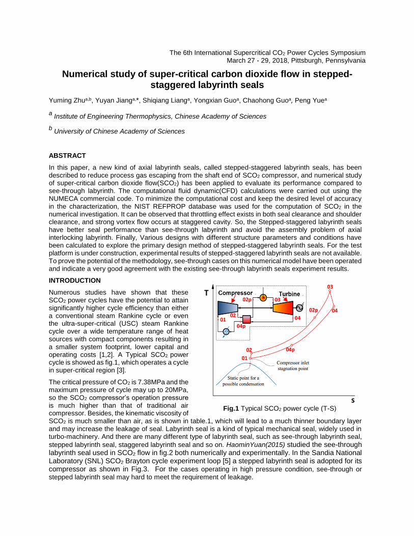
Numerous studies have shown that these SCO2 power cycles have the potential to attain significantly higher cycle efficiency than either a conventional steam Rankine cycle or even the ultra-super-critical (USC) steam Rankine cycle over a wide temperature range of heat sources with compact components resulting in a smaller system footprint, lower capital and operating costs [1,2]. A Typical SCO2 power cycle is showed as fig.1, which operates a cycle in super-critical region [3].
The critical pressure of CO2 is 7.38MPa and the maximum pressure of cycle may up to 20MPa, so the SCO2 compressor’s operation pressure is much higher than that of traditional air compressor. Besides, the kinematic viscosity of SCO2 is much smaller than air, as is shown in table.1, which will lead to a much thinner boundary layer and may increase the leakage of seal. Labyrinth seal is a kind of typical mechanical seal, widely used in turbo-machinery. And there are many different type of labyrinth seal, such as see-through labyrinth seal,
stepped labyrinth seal, staggered labyrinth seal and so on. HaominYuan(2015) studied the see-through labyrinth seal used in SCO2 flow in fig.2 both numerically and experimentally. In the Sandia National Laboratory (SNL) SCO2 Brayton cycle experiment loop [5] a stepped labyrinth seal is adopted for its compressor as shown in Fig.3. For the cases operating in high pressure condition, see-through or stepped labyrinth seal may hard to meet the requirement of leakage.
Fig.1 Typical SCO2 power cycle (T-S)

Axial staggered labyrinth is one of the most powerful labyrinth seal, which is always used in large-scale machinery with split cases in fig.4. As the SCO2 turbine machines have the characteristics of smaller volume and high running speed, turbine rotor system is sensitive to the case assembly error. It is difficult to ensure Installation accuracy for the small-scale split case, so it is in an urgent need for us to develop new kind of axial labyrinth seals to resolve the assembly problem of axial staggered labyrinth and to meet the acquirement of high pressure seal in high speed shaft end. In this paper, a stepped-staggered labyrinth
Table 1 The properties of air and SCO2
Temperature Pressure Density Viscosity Kin. Viscosity
(K) (MPa) (kg/m^3) (uPa-s) (cm^2/s)
Air 320 10 108.26 21.492 0.0019852
SCO2 320 10 448.28 32.388 0.00072251
Fig.2 The see-through labyrinth seal in HaominYuan’s paper
Fig.3 Stepped labyrinth seal used in SNL SCO2 Brayton cycle experiment loop
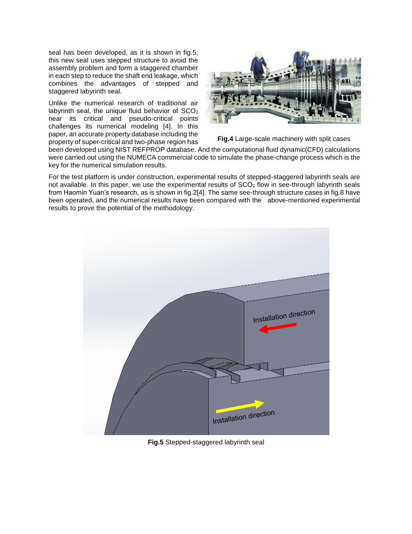
seal has been developed, as it is shown in fig.5, this new seal uses stepped structure to avoid the assembly problem and form a staggered chamber in each step to reduce the shaft end leakage, which combines the advantages of stepped and staggered labyrinth seal.
Unlike the numerical research of traditional air labyrinth seal, the unique fluid behavior of SCO2 near its critical and pseudo-critical points challenges its numerical modeling [4]. In this paper, an accurate property database including the property of super-critical and two-phase region has been developed using NIST REFPROP database. And the computational fluid dynamic(CFD) calculations were carried out using the NUMECA commercial code to simulate the phase-change process which is the key for the numerical simulation results.
For the test platform is under construction, experimental results of stepped-staggered labyrinth seals are not available. In this paper, we use the experimental results of SCO2 flow in see-through labyrinth seals from Haomin Yuan’s research, as is shown in fig.2[4]. The same see-through structure cases in fig.8 have been operated, and the numerical results have been compared with the above-mentioned experimental results to prove the potential of the methodology.
Fig.4 Large-scale machinery with split cases
Fig.5 Stepped-staggered labyrinth seal

Numerical methodology and availability
This chapter describes and discusses the numerical procedure used in this investigation. The first section introduces Navier-Stokes equations and solver algorithm. The second part moves on to describe in detail about the property module of SCO2 and phase-change model. Then different turbulence models will be compared. After that the mesh independent problem will be studied and discussed. And this chapter ends with a comparison between the numerical results and experimental results to prove the availability of the numerical method used in this paper. In this chapter, the inlet condition of see-through structure cases used to verify the availability of the numerical model is set as(10MPa,320K).
2.1 Navier-Stokes equations and solver algorithm
The fluid is simulated using the Reynolds Averaged Navier-Stokes (RANS) equations, applied to a rotating
system. For the single rotating reference frame simulation, the governing equations based on relative
velocity are given by:
Mass conservation
0•r
V
Conservation of momentum
τVVVrrr
P)2( rωωω
Conservation of energy
)(2
1
2
1 22
rrrrVτVVV
TkUVH
rr
where V r is defined as:
rωU
UVV
r
rr
2.2 Model of physical properties
As is reported in [7,8], they used NIST Refprop to formulate a CO2 equation into a two-dimensional table for simulations. The advantage of this method is that the fineness of the table can be controlled by adjusting the number of sampling points in the table and the temperature and pressure ranges covered by the table. Compared with the method of directly invoking the state equation, the method keeps the calculation precision and save the calculation time-consuming. In this paper, we use a software in
Table 2 Two physical tables with different resolutions
P Range T Range Points
MPa K n
Table 1 0.005-800 216-2000 101
Table 2 4-20 270-500 101
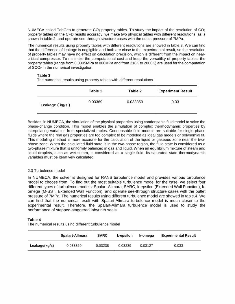
NUMECA called TabGen to generate CO2 property tables. To study the impact of the resolution of CO2 property tables on the CFD results accuracy, we make two physical tables with different resolutions, as is shown in table.2, and operate see-through structure cases with the outlet pressure of 7MPa.
The numerical results using property tables with different resolutions are showed in table.3. We can find that the difference of leakage is negligible and both are close to the experimental result, so the resolution of property tables may have no effect on calculation precision, which is different from the impact on near-critical compressor. To minimize the computational cost and keep the versatility of property tables, the property tables (range from 0.0005MPa to 800MPa and from 216K to 2000K) are used for the computation of SCO2 in the numerical investigation
Besides, in NUMECA, the simulation of the physical properties using condensable fluid model to solve the phase-change condition. This model enables the simulation of complex thermodynamic properties by interpolating variables from specialized tables. Condensable fluid models are suitable for single-phase fluids where the real gas properties are too complex to be modeled as ideal gas models or polynomial fit. This modeling method is more accurate for the calculation of the liquid or gaseous zone near the two-phase zone. When the calculated fluid state is in the two-phase region, the fluid state is considered as a two-phase mixture that is uniformly balanced in gas and liquid. When an equilibrium mixture of steam and liquid droplets, such as wet steam, is considered as a single fluid, its saturated state thermodynamic variables must be iteratively calculated.
2.3 Turbulence model
In NUMECA, the solver is designed for RANS turbulence model and provides various turbulence model to choose from. To find out the most suitable turbulence model for the case, we select four different types of turbulence models: Spalart-Allmara, SARC, k-epsilon (Extended Wall Function), k-omega (M-SST, Extended Wall Function), and operate see-through structure cases with the outlet pressure of 7MPa. The numerical results using different turbulence model are showed in table.4. We can find that the numerical result with Spalart-Allmara turbulence model is much closer to the experimental result. Therefore, the Spalart-Allmara turbulence model is used to study the performance of stepped-staggered labyrinth seals.
Table 3 The numerical results using property tables with different resolutions
Table 1 Table 2 Experiment Result
Leakage(kg/s) 0.03369 0.033359 0.33
Table 4 The numerical results using different turbulence model
Spalart-Allmara SARC k-epsilon k-omega Experimental Result
Leakage(kg/s) 0.033359 0.03238 0.03239 0.03127 0.033

2.4 Mesh independent
To verify the mesh independent and obtain the average number of computational mesh required, three different number of grids have been meshed and each grid number is Mesh1 =14289, Mesh2 = 25833 and Mesh3 = 63348. In order to compare with the experimental data, we operate see-through structure cases with the outlet pressure of 7MPa. The numerical results using physical tables with different resolutions are showed in table.5. From the table, we can find that it will lead to significant error when the mesh is too coarse, so the mesh with mesh number above 30000 is recommended.
2.5 Method availability
To fully evaluate the availability of the above-stated numerical method, more outlet pressure condition has been operated. And the numerical results operated by NUMECA has been compared with the see-through labyrinth seal experimental data and the numerical results operated by OpenFOAM reported in haominyuan[4] shown in fig.6 (in the picture, the red point represent the numerical results operated by NUMECA, the black point represent the numerical results operated by NUMECA and the blue point represent the experimental data). The results operated by numerical method used in this paper shows high degree of coherence with the see-through labyrinth seal experimental data, which proves that this method is feasible and reliable.
Table 4 The numerical results with different number of grids
Mesh1 Mesh2 Mesh3 Experimental Result
Leakage(kg/s) 0.03145 0.033359 0.03282 0.033
Fig 6 The experimental data and the numerical results operated by NUMECA and OpenFOAM

RESULTS AND DISCUSSION
In this chapter, the research structures are described, and numerical results are presented and discussed. First, the detail structure of stepped-staggered labyrinth seal and some structure characteristic parameters are introduced. Then, we compare performance between see-through and the new stepped-staggered labyrinth, and try to explain the difference from details of the flow, including pressure distribution and stream line plot. After that, various designs with different structure parameters and conditions have been calculated to explore the primary design method of stepped-staggered labyrinth seals.
3.1 Structure of stepped-staggered labyrinth seal
As is shown in fig.7, a two-step stepped-staggered labyrinth seal is used to investigate the seal performance and design method of this new seal, and we chose 3 characteristic variables and 4 non-dimensional numbers to describe its detail structure (see table 1). From fig.10, we can find that the installation direction of case wall and shaft wall is opposite, leaving an installation clearance “e” which is one of the main features of the new seal. In this research, we focus on three non-dimensional numbers (a/b, c/b, d/b) and make a primary qualitative research. And the quantitative analysis of effects of 7 variables (including 3 characteristic variables and 4 non-dimensional numbers) will be studied in our future work.
Table 5 The 7 structure variables of stepped-staggered labyrinth seal
definition units
a/b Radial clearance between shaft and
case/ Cavity height
/
c/b Cavity length/ Cavity height /
d/b Tooth width/ Cavity height /
e/b Axial clearance between shaft and
case/ Cavity height
/
n Step number /
r Shaft radius m
b Cavity height m
seal
Fig 7 The structure of stepped-staggered labyrinth seal

3.2 Comparison of sealing performance
To compare the sealing performance of see-through and the new stepped-staggered labyrinth seal, we operate a five-tooth see-through labyrinth in fig.8 with six seal cavities which is the same as the two-step stepped-staggered labyrinth seal in fig.7. Considering the seal size used in actual turbine machine, we set
the shaft radius of all seals to 30mm and the others dimensions are shown in table.6.
In this study, the inlet operating condition is fixed at (10 MPa, 320K) and the outlet pressure ranges from 4MPa to 7MPa. The numerical results are presented in fig.9, and it would be easy to conclude that the new stepped-staggered labyrinth seal has better sealing performance than see-through with the same seal clearance and sealing length. The relative Mach number plots obtained by the CFD in fig.10 also prove the validity of this point. From fig.10, we can find that the relative Mach number distribution of the new labyrinth seal is much more dispersive, which means a much stronger viscous dissipation occurring in seal cavity, so the Mach number is smaller and the seal effect is better.
Fig 8 The structure of five-tooth see-through labyrinth
a/b c/b d/b e/b n r b
0.1 1 0.1 1 2 30mm 1mm
Table 6 The value of stepped-staggered labyrinth seal characteristic dimensions
stepped-staggered labyrinth seal
see-through labyrinth seal
Fig 9 The numerical results of stepped-staggered and see-through labyrinth seal
Leakag
e(k
g/s
)
Outlet Pressure(MPa)
Clearance ratio(a/b)
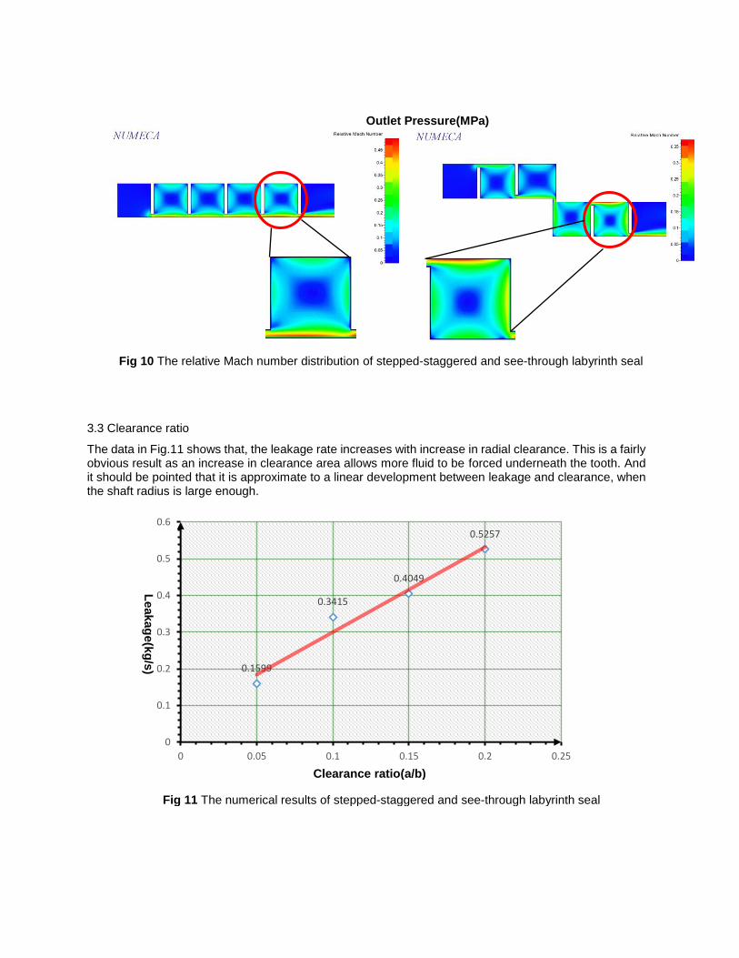
3.3 Clearance ratio
The data in Fig.11 shows that, the leakage rate increases with increase in radial clearance. This is a fairly obvious result as an increase in clearance area allows more fluid to be forced underneath the tooth. And it should be pointed that it is approximate to a linear development between leakage and clearance, when the shaft radius is large enough.
0.1599
0.3415
0.4049
0.5257
0
0.1
0.2
0.3
0.4
0.5
0.6
0 0.05 0.1 0.15 0.2 0.25
Fig 11 The numerical results of stepped-staggered and see-through labyrinth seal
Leakag
e(k
g/s
)
Fig 10 The relative Mach number distribution of stepped-staggered and see-through labyrinth seal

3.4 Length/height ratio
The numerical results of labyrinth with different length/height ratio are compared in fig.12, and we can find that the seal performance is worst when length/height ratio is equal to1, which means a square sealing cavity. Furthermore, it is remarkable that the leakage of the seal (length/height ratio=0.5) is very close to that of the seal (length/height ratio=2). And if we show the data in a log coordinate, as is presented in fig.13, the sealing performance exhibits pretty good symmetry of geometric topology, which is a unique rule and can be a powerful tool to design high-performance mechanical seal.
Though two seals above with similar geometric topology show the same sealing performance, they have the different flow mechanisms as are shown in fig.14. From the streamline patterns, it is obvious that the seal (length/height ratio=0.5) has stronger vortex effect and even emerge additional vortex near the seal clearance and the seal (length/height ratio=2) has a double sealing length to earn a “double” sealing effect.
0.276
0.3415
0.2715
0.2
0.22
0.24
0.26
0.28
0.3
0.32
0.34
0.36
0 0.5 1 1.5 2 2.5
Length/height ratio (c/b)
Leakag
e(k
g/s
)
Fig 12 The numerical results of labyrinth with different length/height ratio
0.276
0.3415
0.2715
0.2
0.22
0.24
0.26
0.28
0.3
0.32
0.34
0.36
0.38
0.4
0.1 1 10
Length/height ratio (c/b)
Leakag
e(k
g/s
)
Fig 13 The numerical results of labyrinth with different length/height ratio (in a log coordinate)

a) length/height ratio=2
b) length/height ratio=1
c) length/height ratio=0.5
Fig 14 The streamline patterns of cases with different length/height ratio
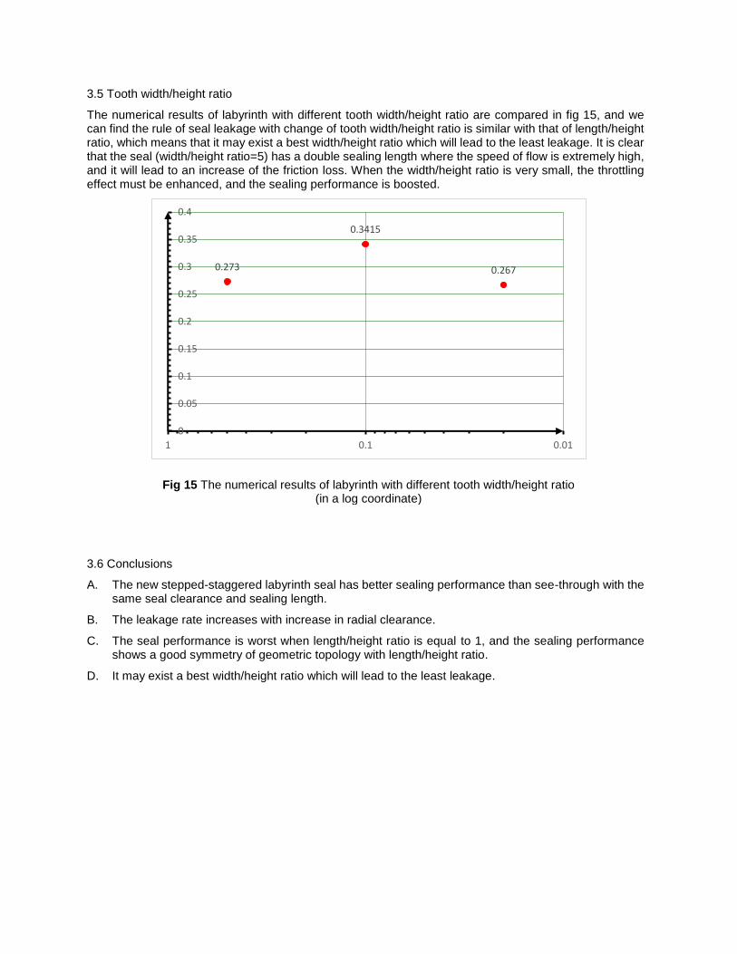
3.5 Tooth width/height ratio
The numerical results of labyrinth with different tooth width/height ratio are compared in fig 15, and we can find the rule of seal leakage with change of tooth width/height ratio is similar with that of length/height ratio, which means that it may exist a best width/height ratio which will lead to the least leakage. It is clear that the seal (width/height ratio=5) has a double sealing length where the speed of flow is extremely high, and it will lead to an increase of the friction loss. When the width/height ratio is very small, the throttling effect must be enhanced, and the sealing performance is boosted.
3.6 Conclusions
A. The new stepped-staggered labyrinth seal has better sealing performance than see-through with the same seal clearance and sealing length.
B. The leakage rate increases with increase in radial clearance.
C. The seal performance is worst when length/height ratio is equal to 1, and the sealing performance shows a good symmetry of geometric topology with length/height ratio.
D. It may exist a best width/height ratio which will lead to the least leakage.
0.267
0.3415
0.273
0
0.05
0.1
0.15
0.2
0.25
0.3
0.35
0.4
0.010.11
Fig 15 The numerical results of labyrinth with different tooth width/height ratio (in a log coordinate)

REFERENCE
[1] Fundamentals and Applications of Super-critical Carbon Dioxide (SCO2) Based Power Cycles.
[2] Supercritical CO2 Power Cycle Developments and Commercialization: Why ScCO2 can Displace Steam.
[3] Monje, B., Sánchez, D., Savill, M., Pilidis, P., & Sánchez, T. (2014). A Design Strategy for Supercritical CO2 Compressors. ASME Turbo Expo 2014: Turbine Technical Conference and Exposition (pp.V03BT36A003-V03BT36A003). American Society of Mechanical Engineers.
[4] Yuan, H., Pidaparti, S., Wolf, M., Edlebeck, J., & Anderson, M. (2015). Numerical modeling of supercritical carbon dioxide flow in see-through labyrinth seals. Nuclear Engineering & Design, 293, 436-446.
[5] Wright, S. A., Radel, R. F., Vernon, M. E., Pickard, P. S., & Rochau, G. E. (2010). Operation and analysis of a supercritical co2 brayton cycle. Sand.
[6] Fairuz, Z. M., & Jahn, I. (2016). The influence of real gas effects on the performance of supercritical co 2, dry gas seals. Tribology International, 102, 333-347.
[7] Rinaldi E, Pecnik R, Colonna P. Exact Jacobians for implicit Navier–Stokes simulations of equilibrium real gas flows[J]. Journal of Computational Physics, 2014,270: 459-477.
[8] E. Rinaldi R P, P. Colonna. Accurate and efficient look-up table approach for dense gas flow simulations[C]. ECCOMAS 2012 - European Congress on Computational Methods in Applied Sciences and Engineering, 2012
ACKNOWLEDGEMENTS
This study was supported by the Institute of Engineering Thermophysics, Chinese Academy of Sciences SCO2 Program (No. Y754026Z11). The authors would like to thank for their support for this research.