Numerical Study of a Hybrid Optical DMT/DFT-S QAM Modulation
10
Numerical Study of a Hybrid Optical DMT/DFT-S QAM Modulation Amin Yekani and Leslie A. Rusch IEEE/OSA Journal of Lightwave Technology, (accepted October 2018) Doi: 10.1109/JLT.2018.2881380 https://ieeexplore.ieee.org/abstract/document/8534352 © 2018 IEEE. Personal use of this material is permitted. Permission from IEEE must be obtained for all other uses, in any current or future media, including reprinting/republishing this material for advertising or promotional purposes, creating new collective works, for resale or redistribution to servers or lists, or reuse of any copyrighted component of this work in other works.
Transcript of Numerical Study of a Hybrid Optical DMT/DFT-S QAM Modulation

Numerical Study of a Hybrid Optical DMT/DFT-S QAM Modulation Amin Yekani and Leslie A. Rusch
IEEE/OSA Journal of Lightwave Technology, (accepted October 2018)
Doi: 10.1109/JLT.2018.2881380
https://ieeexplore.ieee.org/abstract/document/8534352
© 2018 IEEE. Personal use of this material is permitted. Permission from IEEE must be obtained for all other uses, in any current or future media, including reprinting/republishing this material for advertising or promotional purposes, creating new collective works, for resale or redistribution to servers or lists, or reuse of any copyrighted component of this work in other works.

1
Numerical Study of a HybridOptical DMT/DFT-S QAM Modulation
Amin Yekani, Member, IEEE, and Leslie A. Rusch, Fellow, OSA, Fellow, IEEE
Abstract—A hybrid modulation offers the peak-to-averagepower ratio (PAPR) robustness of discrete Fourier transformspread (DFT-S) QAM (quadrature amplitude modulation) withthe bit rate optimization of discrete multi-tone (DMT) modu-lation. We examine via simulation under what circumstancesthis hybrid can increase achievable bit rate. Hybrid PAPRreduction allows us to increase the peak-to-peak voltage at themodulator electrical input to increase the signal mean powerat the modulator output. We propose a methodology to identifythe optimal driving strategy. We optimize the bit rate for theavailable spectrum, i.e., the spectral efficiency, taking into accountthe bandwidth limited nature of the transmitter.
The final optimization we propose is the partition of theavailable spectrum into a lower frequency band for DFT-SQAM and a higher frequency band for DMT. The modulationlevel of the DFT-S QAM is also optimized. We compare theoptimal hybrid performance versus DMT performance for arange of bit rates for a given modulation bandwidth. Improvedperformance comes at the cost of greater DSP complexity for thehybrid solution. We compare the number of complex multipliersrequired to implement hybrid versus DMT for both dispersiveand non-dispersive systems.
Index Terms—DMT, QAM, DFT-spread, hybrid, simulation,frequency optimization, complexity comparison.
I. INTRODUCTION
EVER growing demand for network capacity requiresincreased link speed. This requirement attracts research
groups to enhance digital signal processing techniques bydesigning new modulation formats to increase spectral ef-ficiency, equalize non-flat frequency response, and so on.Discrete multi-tone (DMT) and discrete Fourier transformspread (DFT-S) QAM (quadrature amplitude modulation) aretwo contrasting approaches to this challenge.
DMT divides available spectrum into narrowband subchan-nels, and uses waterfilling techniques to optimally allocatemodulation order and power across these subchannels. Withknowledge of the signal-to-noise ratio (SNR) per subchannel,we can maximize channel capacity. DMT suffers from highpeak to average power ratio (PAPR), leading to higher levels ofquantization noise [1] and amplifier-induced nonlinearities, ascompared to other modulations [2]. The most common methodto reduce PAPR is clipping, this distortion being milder thanthat induced by high PAPR [3].
DFT-S modulation allows frequency domain precompensa-tion, a kind of power allocation not unlike DMT. The PAPRof DFT-S modulation is much lower than that of DMT. Thismethod recently achieved 560 Gbit/s with intensity modulationand direct detection (IM/DD), where four wavelength channelsused DFT-S 128QAM for a 2 km transmission [4].
Unlike DMT modulation, DFT-S cannot assign a non-uniform number of bits per frequency subdivision, as mod-
ulation occurs in the time domain before the fast Fouriertransform (FFT). This precludes DFT-S from maximizingcapacity. Combining DFT-S with DMT in a hybrid modulationwe can seek PAPR reduction (as compared to DMT alone),while enhancing spectral efficiency (as compared to DFT-Salone). This approach was used with IM/DD when combiningPAM and DMT [5], and combining OFDM with PAM in ahybrid fiber-visible laser light system [6].
Despite these IM/DD demonstrations, the increase in com-plexity of hybrid modulation can be difficult to justify incost-sensitive short haul applications. Coherent detection sys-tems over metro or long haul are more suitable for hy-brid DMT/DFT-S modulation. Hybrid modulation experimentswere recently reported with 25 Gb/s vertical cavity surfaceemitting laser technology in [7] using direct detection, and inour work with a silicon photonics Mach Zehnder IQ modulator[8] with coherent detection. No systematic evaluation of theadvantages of the hybrid in coherent detection has yet appearedfor these systems.
In this paper we study the optimization of joint DMT andDFT-S QAM modulation to increase bit rate, and/or spectralefficiency in coherent detection systems. We provide a tech-nique to find optimal hybrid modulation parameters. We studythe trade-off between modulator nonlinearity (induced by highPAPR) and AWGN noise in terms of modulator optical outputpower or electrical input peak-to-peak voltage (Vpp). From thisstudy we derive a driving strategy that minimizes BER for ahybrid modulation, while taking into account the bandwidthlimited nature of the transmitter. We propose a partition ofthe available spectrum into a higher frequency band for DMTand a lower frequency band for DFT-S (at optimized QAMmodulation level). We compare the performance of optimalhybrid to that of simple DMT for a range of bit rates for agiven modulation bandwidth.
Section II starts with the principals of the hybrid approach.We describe the simulation model and transmitter and receiverside DSP. In section III, we study the hybrid of uniform DMTand DFT-S QAM to find Vpp yielding minimum BER. Insection IV we optimize the modulation order for QAM, aswell as the frequency band partition between DFT-S QAMand DMT. In the end of section IV we compare the optimizedhybrid with standard DMT. Section V is dedicated to acomplexity comparison of hybrid modulation and standardDMT. Section VI offers some concluding remarks.
II. PRINCIPLES OF HYBRID MODULATIONAND REQUIRED DSP
Unlike DMT, PAPR for single carrier modulation can bevery low. PAPR varies with pulse shaping; for raised cosine
Copyright (c) 2018 IEEE. Personal use is permitted. For any other purposes, permission must be obtained from the IEEE by emailing [email protected].
2
pulse shaping, PAPR is lowest for rectangular pulses and largest for sinc pulses (also known as Nyquist pulses). While Nyquist pulses have the highest PAPR, they have the best spectral efficiency, equal t o t hat of DMT.
DFT-S is a frequency domain implementation of the Nyquist single carrier approach - an alternative to raised cosine ap-proximations to the sinc pulse. With DFT-S, QAM data is generated in the time domain and moved to the frequency domain using a fast Fourier transform (FFT). In the frequency domain we sculpt frequency occupancy, also constraining it to a limited bandwidth. An inverse fast Fourier transform (IFFT) moves data back to the time domain. Sculpting the signal in the frequency domain helps us to adapt the waveform to channel characteristics.
As explained in the introduction, we create a hybrid modu-lation by combining DFT-S QAM signal in lower frequencies (where the frequency response is almost flat a nd t he l ack of bit allocation is less critical) and DMT in higher frequencies. The single carrier DFT-S QAM part of the combination lowers PAPR (compared to DMT), and the DMT part of helps us max-imize throughput (compared to DFT-S QAM) using proper bit allocation and power allocation. Details of this combination is explained in this section. We present our simulation model and our estimation of SNR (per subchannel in the case of the DMT part). We describe transmitter side DSP for signal sculpting, as well as receiver side DSP. The description covers hybrid modulation; when the DFT-S part is set to zero, it covers standard DMT as well.
A. Simulation Model
Figure 1 shows the the simulation model, transmitter sideDSP, and receiver side DSP for the hybrid modulation format.The simulator introduces nonlinear behavior in the digital toanalog conversion and the sinusoidal transfer function of themodulator. The only noise sources are additive white Gaussiannoise (AWGN).
The first block in our simulation model is a digital to aconverter (DAC) with high resolution (8-bit) and a 64 GSam-ple/s sampling rate. The bandwidth limitations of the DAC andmodulator are simulated with a single low pass Gaussian filter.The modulator is biased at the null point and has the typicalsinusoidal transfer function, normalized so that the maximumamplitude input voltage of Vπ/2 generates an output signalequal to one. The mismatch between the local oscillator andthe transmit laser is modeled with a random frequency offset,uniformly distributed between 0 and 500 MHz. The laser ismodeled as having phase noise described by a Wiener processand parameterized by a 100 kHz linewidth. Finally, AWGNis added to reflect the noise level being examined. The keysimulation parameters are summarized in Table I.
B. Transmitter DSP
Before starting transmitter-side DSP, we estimate the SNRthat will be used for waterfilling and for power allocationbetween the DMT and the DFT-S QAM portions of thespectrum. In this block, we fix the percentage of availablespectrum allocated to DFT-S QAM, illustrated as a block of
TABLE IKEY SIMULATION PARAMETERS
Parameter Value
DAC 28-bit + 64 GSample/sLaser Phase noise with Wiener process (LW = 100 kHz)
Modulator LPF + Transfer function nonlinearityFrequency offset Random number between 0-500 MHz
NQAM subchannels at baseband, and NDMT subchannels athigher frequency. We then run a simulation transmitting QPSKsignals with uniform power allocations for DFT-S QAM andDMT. DMT subchannels with the same power level and modu-lation (QPSK), i.e., uniform DMT is also known as orthogonalfrequency division multiplexing (OFDM). At the receiver weestimate the SNR per subchannel for the DMT spectra, andoverall SNR for the DFT-S QAM spectrum using techniquesdescribed in [9]. This is repeated for each partitioning of thespectrum that we examine.
The total FFT size is NFFT = NDMT +NQAM , as illus-trated in Fig. 1. The ratio NFFT /NQAM gives the percentageof spectrum allocated to DFT-S QAM. The transmitter sideDSP starts with generating a pseudo-random bit sequence(PRBS) of order 22. For a fixed hybrid (DFT-S QAM mod-ulation level and percentage of spectrum), we divide the bitsequence appropriately between the two branches in the TXDSP section of Fig. 1.
For a fixed hybrid (modulation order for DFT-S andNQAM ), we calculate the power allocation for the DFT-Spartition as the amount of power needed to achieve a targetBER of 10−3 based on overall QAM SNR. For the DMTportion, we use Chow’s waterfilling algorithm [10], to allocatepower again with target BER of 10−3. The bit allocation stepof waterfilling [10] spreads the DMT bits among subchannels(NDMT in Fig. 1) to achieve the target bit rate. Target bit rateis adjusted to find the highest bit rate achievable.
Modulated QAM symbols for the DFT-S spectrum aremoved to the frequency domain with a fast Fourier transform(FFT) block. In the frequency domain the DFT-S data is con-catenated with DMT data to fill the entire available spectrumas illustrated in cartoons in Fig. 1. Finally, a preamble is addedfor frequency offset estimation. The frequency domain signalis moved to the time domain using an inverse fast Fouriertransform (IFFT) block. The last stage is parallel to serialconversion.
C. Receiver DSP
The receiver side DSP starts with an FFT block to move thetime domain signal into the frequency domain. We then applyfrequency offset compensation (FOC) using the Schmidel-Coxalgorithm [11]. After FOC, we separate QAM data from DMT.In the DMT side we apply carrier phase recovery (CPR), thenone tap equalization and finally we estimate BER.
For the QAM data, we first pass through a parallel to serialblock. We then apply blind channel equalization using anN1 tap multi-modulus algorithm (MMA) at two samples persymbol [12]. We next down sample the data to one sample
Copyright (c) 2018 IEEE. Personal use is permitted. For any other purposes, permission must be obtained from the IEEE by emailing [email protected].

3
Power allocation
Generate PRBS
SNR Estimation
QAM Mod.
FFT (NQAM)
Power allocation
DMT Mod.
Hybrid frames
IFFT (NFFT)
Parallel to serial
TX DSP
Bit allocation
Simluator RX DSP
Freq.
NQAM NDMT
NFFT
FFT (NFFT)
Serial to parallel
FOC
1tap Equalizer
BER calculation
IFFT (NQAM)
MMA (N1)
CPR
DD-LMS (N2)
CPR
DAC
(8-bit 64 GSamp/s)
Low pass filter
Modulator nonlinear
transfer function
Random frequency
offset
Laser (100 kHz
linewidth)
AWGN
Fig. 1. Monte Carlo simulation block diagram (center panel) and flowcharts for hybrid modulation for transmitter-side (left panel) and receiver-side (rightpanel) DSP.
per symbol and go into the CPR block. After CPR we apply aN2 tap decision-directed least mean square error (DD-LMS)equalizer and finally we calculate BER.
We used the same CPR technique for both QAM and DMT.We use a small portion of the data in each frame (1/30) toestimate phase rotation for that frame. This estimated phaseis applied to all samples of the frame. This method has lowercomplexity than blind search [13] or other CPR methods. Biterror rate was estimated via Monte Carlo methods, testing2× 107 bits and counting a minimum of 20 errors.
III. DRIVING STRATEGY FOR HYBRID MODULATION
In this section, we show that increasing the DFT-S portionof the hybrid decreases the PAPR for the hybrid modulation.Then we study the trade-off between AWGN noise and themodulator nonlinear transfer function. From this trade-off wederive a driving strategy for the modulator to minimize BERfor a specific hybrid spectral partition, OSNR value, andmodulator bandwidth. Following that we optimize modulationorder and frequency occupation for DFT-S portion for a fixedbit rate. Finally we find the maximum bit rate under theforward error correction (FEC) threshold for optimized hybridmodulation and compare it to standard DMT.
A. Impact of hybrid spectral partition on PAPR
As explained in the introduction, the main reason to com-bine DFT-S QAM and DMT is to reduce PAPR. Quantizationnoise is negligible when using a high resolution (8-bit) DAC,but transfer function nonlinearity can be severe in the presenceof high PAPR. The nonlinear distortion is most severe forlarge excursions from the mean value. The higher the PAPR,The greater the probability of such excursion occurring. Theprobability of the excursion above the mean is a good predictorof PAPR impact. Typically, excursions of 9.5 dB above themean value are considered to generate excessive nonlineardistortion.
In Fig. 2 we plot the probability of exceeding the meanby a certain excursion level in dB for three hybrid spectralpartitions. In the first case we generate uniform DMT, second
Fig. 2. Probability of exceeding at any instance a certain level of excursionfrom the signal mean value for: strictly uniform 64QAM DMT, strictly DFT-S64 QAM, and a hybrid of half spectrum uniform 64QAM DMT and halfspectrum DFT-S 64QAM.
one is a combination of 50% DMT and 50% DFT-S QAM,and the last one is all DFT-S QAM.
Consider the excursion level of 9.5 dB, where nonlineardistortion limits performance. At this level, uniform DMThas 10% of samples distorted. By using a 50-50 hybrid thisprobability is decreased to 2%. For the case of all DFT-S QAMmodulation, only 0.1% of samples are distorted, which isnegligible. Clearly DFT-S QAM has lower PAPR, as expectedand by adjusting the mix of DMT and DFT-S we can tune thelevel of PAPR. That is, varying the percentage of DFT-S QAMcan shift the plot in Fig. 2 any where between the two extremesof all uniform DMT and all DFT-S QAM.
B. Driving strategy minimizing BER
Nonlinearity induced by the modulator sinusoidal transferfunction can be reduced by lowering mean power, i.e., op-erating at lower Vpp. While low Vpp reduces nonlinearity, itdecreases OSNR as well. Proper choice of Vpp balances thesetwo effects to minimize BER. We examine the trade-off tofind the optimal driving strategy for two cases: for modulatorbandwidth much greater than required for the transmission
Copyright (c) 2018 IEEE. Personal use is permitted. For any other purposes, permission must be obtained from the IEEE by emailing [email protected].

4
0.1 0.2 0.3 0.4 0.5 0.6 0.7 0.8 0.9Modulator Normalized Power (mW)
10-5
10-4
10-3
10-2
10-1
100
BE
R
-7
Modulator Normalized Power (dBm)
-5.2 -4 -3 -2.2 -1.5-10 -1 -0.4
all uniform DMT50% DFT-S 64QAMall DFT-S 64QAM
PN = -15dBmPN = -25dBmPN = -35dBm
Fig. 3. BER versus normalized modulator output power at three noise levelsfor: strictly uniform 64QAM DMT, strictly DFT-S 64 QAM, and a hybrid ofhalf spectrum uniform 64QAM DMT and half spectrum DFT-S 64QAM.
rate (infinite bandwidth) and for bandwidth limited operation,i.e., high bit rates. We used Monte Carlo techniques in thesimulator shown in Fig. 1 to calculate the BER for each casein this section.
1) Influence of noise level for infinite bandwidth: In thissubsection we continue to use uniform DMT, leaving powerand bit allocations for following sections. The low pass filter inFig. 1 is not present for simulations of this infinite bandwidthcase. The noise levels are fixed for the simulation. In this waywe can set the noise level independently of the bandwidthassumption.
Figure 3 shows the BER versus normalized modulatoroutput power for three values of noise power (PN ): -35 dBm,-25 dBm, and -15 dBm. We swept normalized modulatoroutput power by changing the peak-to-peak voltage, while wefixed the bias at the null point. For each value of PN weconsider the three modulations for which we found the PAPRcumulative distribution function in Fig. 2.
Lowering PAPR with a fixed OSNR reduces the effect ofmodulator transfer function nonlinearity, decreasing the BER.This effect can be seen no matter the level of PN . This isalso true when sweeping the x-axis. The BER performanceis best for full DFT-S QAM, followed by the 50% hybrid,and uniform DMT has the worst performance. The BER trendfollows the PAPR cumulative distribution function.
Consider the optimum values for modulator output powerfor all nine cases shown in Fig. 3. The optimum value changessignificantly with the noise level. For a fixed noise level,however, the minimum BER occurs at roughly the samenormalized modulator power no matter the PAPR level, i.e, nomatter the hybrid partition. The optimum region of normalized
modulator power is shaded for each noise power case, e.g.,the red region (around 0.35 mW) covers the case of PN =−35 dBm. If we increase noise level by 10 dB the optimumvalue increases to around 0.55 mW. Greater modulator outputpower is required as we are AWGN noise limited rather thanPAPR limited. Further increase in noise power up to -15 dBmincreases the optimum value of modulator output power toaround 0.75 mW.
Limiting the bandwidth of the system could reduce PAPRof the signal by attenuating higher frequencies and avoidingsudden changes in the amplitude of the signal. For differentvalues of modulator bandwidth the value of OSNR will bethe same if we keep modulator output power unchanged.Therefore we expect changing system bandwidth should havenegligible effect on the optimum value of modulator outputpower, for the same reasons this was the case when changingthe hybrid spectral partition between DFT-S and DMT. Weexamine this hypothesis in the following.
2) Influence of noise level for finite bandwidth: For therest of the paper our simulator includes a low pass Gaussianfilter with a 3 dB bandwidth of 25 GHz. When the systembandwidth is limited, optimized DMT uses waterfilling toadapt the signal to the channel frequency response, thusoutperforming uniform DMT. For the balance of the paper,we maximize capacity by allocating the appropriate power andnumber of bits per symbol at each subchannel.
The AWGN noise power is set to -33 dBm, a reasonablevalue for a 25 GHz receiver. From Fig. 3, at this noise levelthe modulator normalized power should be around 0.4 mWto minimize BER, regardless of hybrid split or the systembandwidth. This modulator output power corresponds to 29 dBOSNR, which is a reasonable value for a back-to-back exper-iment.
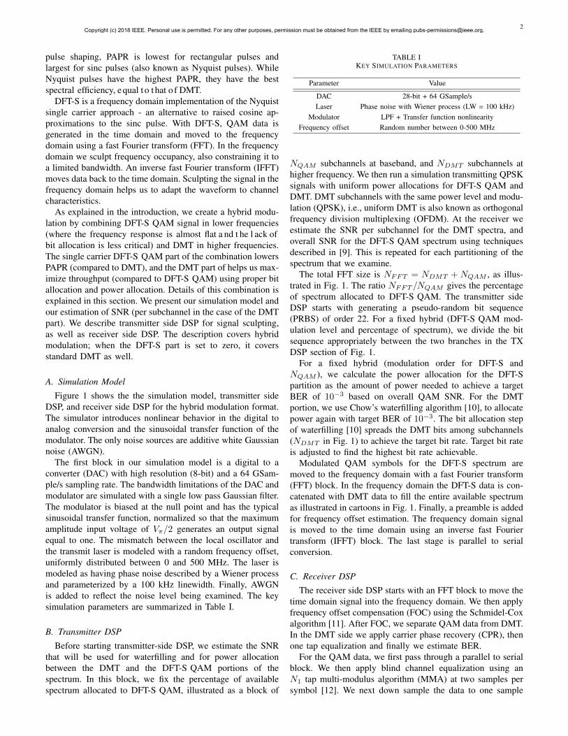
Figure 4 shows the BER versus modulator output powerfor four different hybrid combinations, all of which achievea bit rate of 260 Gb/s. The DFT-S 64QAM portion of thefour hybrid modulations examined has bit rate varying from100 Gb/s to 240 Gb/s; the balance of the 260 Gb/s is coveredby the waterfilled DMT. The percentage noted beside the curvegives the DFT-S QAM bandwidth as a percentage of the totalbandwidth covered by the FFT (64 GHz in our simulations).Figure 4 confirms that the optimal modulator output power isaround 0.42 mW, which is in less than 0.1 mW range fromwhat we predicted for infinite bandwidth in Fig. 3. While notreported here, we confirmed the same behavior for a varietyof system bit rates and bandwidths. In all cases, the optimummodulator output power is not affected by the hybrid spectralallocation, nor by the system 3 dB bandwidth.
IV. OPTIMIZING BIT RATE
By changing the hybrid spectral allocation to place the splitbetween DMT and DFT-S QAM at higher frequencies, weincrease the DFT-S portion and decrease the PAPR of theoverall signal. Lower PAPR means lower nonlinear distortionand better performance. Placing the split point too high leadsto limited bandwidth to meet DMT bit rate targets. This willforce the waterfilling to go to advanced QAM orders that
Copyright (c) 2018 IEEE. Personal use is permitted. For any other purposes, permission must be obtained from the IEEE by emailing [email protected].
5
62%
0.2 0.3 0.4 0.5 0.6 0.7Modulator Normalized Power (mW)
10-6
10-5
10-4
10-3
10-2
10-1
BE
R
100 Gb/s 64QAM + 160 Gb/s DMT160 Gb/s 64QAM + 100 Gb/s DMT200 Gb/s 64QAM + 60 Gb/s DMT240 Gb/s 64QAM + 20 Gb/s DMT
-7
Modulator Normalized Power (dBm)
-5.2 -4 -3 -2.2 -1.5
62%
52%
41%26%
Fig. 4. For overall bit rate of 206 Gb/s, noise power of -33 dBm, and 25 GHzsystem bandwidth: BER versus normalized modulator output power for fourdifferent hybrid spectral allocations.
require strong SNR. At these high frequencies, however, theSNR will be limited as the channel rolls off. This is reflectedin Fig. 4 where we see BER improvement until 52%, and arapid deterioration at 62%.
In the first subsection, we find the optimal split pointassuming a fixed QAM level for the DFT-S QAM section.This optimization is done for each candidate QAM level. For agiven overall bit rate, we identify the best split point and QAMorder to minimize BER. We compared the optimized hybridwith DMT for different bit rates in the second subsection. Aspreviously, the OSNR is 29 dB, modulator output power is0.4 mW, and system 3 dB bandwidth is 25 GHz.
A. Fixed QAM level for DFT-S
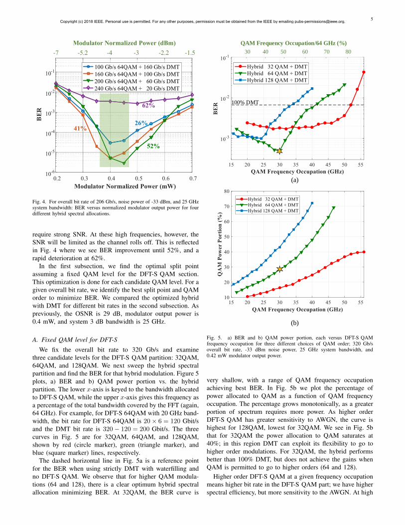
We fix the overall bit rate to 320 Gb/s and examinethree candidate levels for the DFT-S QAM partition: 32QAM,64QAM, and 128QAM. We next sweep the hybrid spectralpartition and find the BER for that hybrid modulation. Figure 5plots, a) BER and b) QAM power portion vs. the hybridpartition. The lower x-axis is keyed to the bandwidth allocatedto DFT-S QAM, while the upper x-axis gives this frequency asa percentage of the total bandwidth covered by the FFT (again,64 GHz). For example, for DFT-S 64QAM with 20 GHz band-width, the bit rate for DFT-S 64QAM is 20× 6 = 120 Gbit/sand the DMT bit rate is 320− 120 = 200 Gbit/s. The threecurves in Fig. 5 are for 32QAM, 64QAM, and 128QAM,shown by red (circle marker), green (triangle marker), andblue (square marker) lines, respectively.
The dashed horizontal line in Fig. 5a is a reference pointfor the BER when using strictly DMT with waterfilling andno DFT-S QAM. We observe that for higher QAM modula-tions (64 and 128), there is a clear optimum hybrid spectralallocation minimizing BER. At 32QAM, the BER curve is
100% DMT
QAM Frequency Occupation/64 GHz (%)
40 60 705030 80
(a)
(b)
Fig. 5. a) BER and b) QAM power portion, each versus DFT-S QAMfrequency occupation for three different choices of QAM order; 320 Gb/soverall bit rate, -33 dBm noise power, 25 GHz system bandwidth, and0.42 mW modulator output power.
very shallow, with a range of QAM frequency occupationachieving best BER. In Fig. 5b we plot the percentage ofpower allocated to QAM as a function of QAM frequencyoccupation. The percentage grows monotonically, as a greaterportion of spectrum requires more power. As higher orderDFT-S QAM has greater sensitivity to AWGN, the curve ishighest for 128QAM, lowest for 32QAM. We see in Fig. 5bthat for 32QAM the power allocation to QAM saturates at40%; in this region DMT can exploit its flexibility to go tohigher order modulations. For 32QAM, the hybrid performsbetter than 100% DMT, but does not achieve the gains whenQAM is permitted to go to higher orders (64 and 128).
Higher order DFT-S QAM at a given frequency occupationmeans higher bit rate in the DFT-S QAM part; we have higherspectral efficiency, but more sensitivity to the AWGN. At high
Copyright (c) 2018 IEEE. Personal use is permitted. For any other purposes, permission must be obtained from the IEEE by emailing [email protected].

6
frequency occupation (35% and higher), we see in Fig. 5a the typical relative performance: lowest BER for 32QAM and highest BER for 128QAM. At lower occupation (33% and below), we see the trade-off in the hybrid modulation: lower BER by balancing the PAPR (nonlinear) and AWGN (linear) impairments.
More power devoted to QAM means more PAPR reduction; at the same time, it reduces the DMT power allocation making it harder to achieve the DMT BER target. This trade-off is visible in the intersecting curves and clear minima (64QAM and 128QAM cases) in Fig. 5a BER curves. For instance, at 22 GHz the curves for 64QAM and 128QAM BER intersect. Above 22 GHz DFT-S 64QAM is a better choice, as DMT does not have enough resources (power and spectrum) to overcome the restrictions imposed by noise sensitivity in DFT-S 128QAM. The minima occur when the two DMT effects (PAPR advantage, power allocation disadvantage) bal-ance.
Returning to 32QAM, this is clearly not a good choice for the 320 Gb/s target. The flat p art o f t he c urve s hows there is a balance in reduced PAPR and limited DMT frequency range. For 320 Gb/s, the best choice is 64QAM with 30%QAM frequency occupation, as shown in Fig. 5a and 5a by a gold star. Despite the nonlinear curves in Fig. 5b, the optimal power allocation happens to be about 30% (y-axis) as well.
B. Best hybrid for bit rate
We repeated the optimization procedure described in the lastsubsection as we swept bit rates. The highest modulation levelfor a DMT subchannel was 128QAM, hence the modulationlevels we examined for DFT-S QAM were sufficient to coverachievable performance. Figure 6 shows a plot of BER forthe best choice of hybrid configuration in red (star markers).The maximum bit rate under the FEC threshold of 3.8e-3 (7%overhead hard decision FEC) for DMT alone is 320 Gb/s. Thisrate increases to 360 Gb/s if we use hybrid modulation. Asthe bit rate decreases, the performance enhancement of thehybrid decreases. Pushing to these aggressive bit rates in a 64GHz bandwidth (see spectral efficiency given in upper axis),requires a DMT portion with a high bit allocation. However,including more DMT leads to less the PAPR reduction.
Figure 7 shows the hybrid spectral allocation that yieldedthe best performance for each bit rate, i.e., the DFT-S fre-quency occupation for the points in Fig. 4. From 260 to340 Gb/s, the best constellation for DFT-S QAM is 64QAM.Above 340 Gb/s, it is better to reduce frequency occupationand increase QAM order to send more bits over a smallerfrequency range; DMT waterfilling over more frequency binsallows the bit rate to grow.
C. Experimental validation
In [8], we reported an experimental investigation of thehybrid modulation, but without optimization of the drivingstrategy outlined in section III. In that experiment, we ex-amined only 16QAM for the DFT-S portion, but at threedifferent frequency occupations. The 100% DMT case wasalso examined. We used a silicon photonic traveling wave
FEC = 3.8e-3
Fig. 6. For noise power of -33 dBm, 25 GHz system bandwidth, andmodulator output power of 0.42 mW: BER versus bit rate for 100% DMT(blue circle markers) and best choice of hybrid (red star markers).
64QAM
128QAM
Fig. 7. For noise power of -33 dBm, 25 GHz system bandwidth, andmodulator output power of 0.42 mW: Best hybrid spectral allocation fortargeted bit rates; best DFT-S QAM modulation was 64QAM for bit ratesup to and including 340 Gb/s, 128QAM at 360 Gb/s and higher.
modulator with a 3 dB bandwidth of 20 GHz. Due to couplinglosses, the OSNR was limited to 23 dB. The 20 GHz band andwas divided into 256 subbands for the hybrid modulation; atotal of 120 Gb/s was transmitted.
Details of our experimental setup are provided in section IIIof [8], while Fig. 8 shows the BER versus bit rate achieved.Pure DMT (blue, circle markers) has higher error rate thanall three hybrid modulation scenarios. When sweeping theDFT-S frequency occupancy from 25% to 35% we can seethe importance of PAPR mitigation peaking and diminishing.From 25% occupancy (representing 64 Gb/s of the total120 Gb/s) we increase to 31% (80 Gb/s) to see the bestperformance. Increasing occupancy beyond this point leadsto a small power allocation to DMT that causes a decreasein performance. At 35% occupancy, the hybrid performanceis worse than pure DFT-S, i.e., DMT is not helping. Thisvalidates our simulation results in Fig. 5a, where we have anoptimum QAM frequency occupation.
Copyright (c) 2018 IEEE. Personal use is permitted. For any other purposes, permission must be obtained from the IEEE by emailing [email protected].

7
Fig. 8. Experimental comparison [8] at 120 Gb/s between pure DMT andthree hybrid modulations with different DFT-S frequency occupations; thedriving strategy in section III is not used in experimentation.
V. COMPLEXITY INCREASE WITH HYBRID
Using a hybrid modulation format enhances system perfor-mance, but requires additional DSP blocks for both DMT andQAM subsystems. Such extensive DSP increases the complex-ity and implementation cost. In this section, we calculate thecomplexity of hybrid modulation and compare it to DMT. Wefirst identify DSP blocks that represent the largest portion ofprocessing complexity, and then focus on the the complexityfor these blocks.
Whether implemented in an application specific integratedcircuit (ASIC) or a field programmable gate array (FPGA),the latency of a multiplier is greater than that of an adder. Butmore importantly, the cost and chip space of a multiplier ismuch higher than that of an adder. Therefore, we restrict ourcomplexity analysis to the number of multipliers per bit.
In the next subsections we assume zero dispersion, andfocus on the complexity of hybrid modulation alone. In thefinal subsection, we discuss how a dispersion compensationblock impacts the overall complexity when using a hybrid.
A. Common and negligible DSP operations
The DSP tasks in Fig. 1 are formatted to identify DSPrelevance to our comparison of complexity. All white boxesare DSP needed for both QAM and DMT modulations andare not considered as additional complexity vis-a-vis standardDMT. DSP blocks unique to DFT-S QAMor DMT are shownwith blue and green boxes, respectively.
Blocks with high complexity are shown with rounded edgesin Fig. 1. On the transmitter side, we have an FFT stagefor the DFT-S QAM DSP flow, and an IFFT block for thehybrid signal that contribute significantly to complexity. Onthe receiver side, system complexity is determined by the FFTstage for hybrid signal, and the IFFT block and MMA andDD-LMS equalizers for the DFT-S QAM DSP flow.
To decrease complexity of implementing hybrid modulationwe can share the FOC block. The offset estimation is per-formed after the initial FFT and before splitting the subchanneldata between the two DSP flows. We use two frames as apreamble for frequency offset estimation and compensation.Implementing the FOC in an ASIC is simple and could beneglected compare to the other DSP sections [14].
The carrier phase recovery stage was explained in previoussections. We use a training-symbol-based (data aided) algo-rithm, with a single phase shift for each frame of data forboth DMT and DFT-S QAM. The complexity of this CPRmethod is much lower than that of the blind equalizationblocks (MMA or DD-MLS), and therefore it can be neglectedin our complexity comparison.
B. Implementation complexity of main contributors
Next we calculate number of complex multipliers for DSPblocks with high complexity and estimate the overall com-plexity for hybrid and DMT. Blocks with dominant DSPcomplexity in this paper can be divided in two categories:FFT/IFFT and equalizers. In the next two subsections wecalculate number of complex multipliers per signal symbol(CPS) in FFT/IFFTs and equalizers.
1) FFT + IFFT: The implementation complexity for FFTand IFFT are the same. Each requires N log2(N)/2 complexmultipliers implemented with a radix-2 algorithm, where N isthe smallest power of two greater than or equal to the targetFFT length. For highest efficiency of hardware resources, wechoose a power of two for FFT size. Radix-4 is can be used toimplement the FFT and requires only 3N log(N)/8 multipli-ers; however, requiring a power of four limits the options forFFT size even more [15], [16]. We chose the popular radix-2algorithm for its popularity and greater freedom in choosingFFT length. CPS for a combined FFT and IFFT blocks is
CPSradix−2FFT+IFFT = 2× log2(N)/2 = log2(N). (1)
2) Equalizer: Any equalizer can be implemented in thetime domain (TDE) or the frequency domain (FDE). Thecomputational complexity for FDE is much lower than TDE[17], [18], so we consider only FDE for our comparison.
Consider a frequency domain equalizer with Neq taps andNSPS samples per symbol. To obtain Neq/NSPS outputsymbols, we need Neq complex multipliers to calculate theequalizer output, and Neq complex multipliers to updateequalizer taps. Furthermore, we need to eight length Neq FFTs[15]. The CPS for an equalizer with Neq taps, and NSPS
number of samples per symbol using FDE technique is
CPSFDEEQ = [2Neq + 4Neq log2(Neq)]NSPS/Neq (2)
C. Number of multipliers per bit
CPS is a good figure metric for system complexity, but itcannot show the hardware efficiency with bit rate. For sucha comparison it is better to calculate the number of requiredmultiplexers per bit (CPB) which is
CPB = CPS/(BR/BW ), (3)
Copyright (c) 2018 IEEE. Personal use is permitted. For any other purposes, permission must be obtained from the IEEE by emailing [email protected].
8
where BR is the overall bit rate of the system, and BW is the overall frequency range covered by DAC (64 GHz in our work). BR/BW shows the number of bits per single symbol that is uploaded to the DAC.
D. Quantifying multiplies/bit
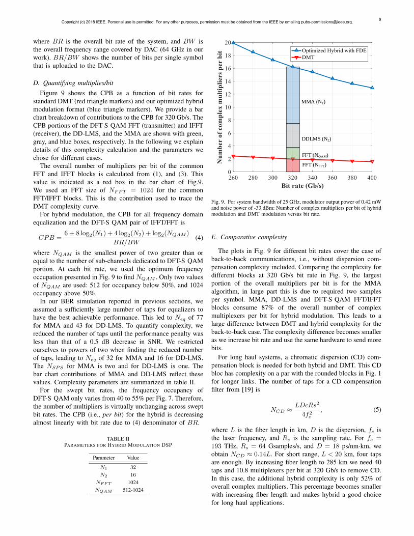
Figure 9 shows the CPB as a function of bit rates forstandard DMT (red triangle markers) and our optimized hybridmodulation format (blue triangle markers). We provide a barchart breakdown of contributions to the CPB for 320 Gb/s. TheCPB portions of the DFT-S QAM FFT (transmitter) and IFFT(receiver), the DD-LMS, and the MMA are shown with green,gray, and blue boxes, respectively. In the following we explaindetails of this complexity calculation and the parameters wechose for different cases.
The overall number of multipliers per bit of the commonFFT and IFFT blocks is calculated from (1), and (3). Thisvalue is indicated as a red box in the bar chart of Fig.9.We used an FFT size of NFFT = 1024 for the commonFFT/IFFT blocks. This is the contribution used to trace theDMT complexity curve.
For hybrid modulation, the CPB for all frequency domainequalization and the DFT-S QAM pair of IFFT/FFT is
CPB =6 + 8 log2(N1) + 4 log2(N2) + log2(NQAM )
BR/BW(4)
where NQAM is the smallest power of two greater than orequal to the number of sub-channels dedicated to DFT-S QAMportion. At each bit rate, we used the optimum frequencyoccupation presented in Fig. 9 to find NQAM . Only two valuesof NQAM are used: 512 for occupancy below 50%, and 1024occupancy above 50%.
In our BER simulation reported in previous sections, weassumed a sufficiently large number of taps for equalizers tohave the best achievable performance. This led to Neq of 77for MMA and 43 for DD-LMS. To quantify complexity, wereduced the number of taps until the performance penalty wasless than that of a 0.5 dB decrease in SNR. We restrictedourselves to powers of two when finding the reduced numberof taps, leading to Neq of 32 for MMA and 16 for DD-LMS.The NSPS for MMA is two and for DD-LMS is one. Thebar chart contributions of MMA and DD-LMS reflect thesevalues. Complexity parameters are summarized in table II.
For the swept bit rates, the frequency occupancy ofDFT-S QAM only varies from 40 to 55% per Fig. 7. Therefore,the number of multipliers is virtually unchanging across sweptbit rates. The CPB (i.e., per bit) for the hybrid is decreasingalmost linearly with bit rate due to (4) denominator of BR.
TABLE IIPARAMETERS FOR HYBRID MODULATION DSP
Parameter Value
N1 32
N2 16
NFFT 1024NQAM 512-1024
MMA (N1)
DDLMS (N2)
FFT (NQAM)
FFT (NFFT)
Fig. 9. For system bandwidth of 25 GHz, modulator output power of 0.42 mWand noise power of -33 dBm: Number of complex multipliers per bit of hybridmodulation and DMT modulation versus bit rate.
E. Comparative complexity
The plots in Fig. 9 for different bit rates cover the case ofback-to-back communications, i.e., without dispersion com-pensation complexity included. Comparing the complexity fordifferent blocks at 320 Gb/s bit rate in Fig. 9, the largestportion of the overall multipliers per bit is for the MMAalgorithm, in large part this is due to required two samplesper symbol. MMA, DD-LMS and DFT-S QAM FFT/IFFTblocks consume 87% of the overall number of complexmultiplexers per bit for hybrid modulation. This leads to alarge difference between DMT and hybrid complexity for theback-to-back case. The complexity difference becomes smalleras we increase bit rate and use the same hardware to send morebits.
For long haul systems, a chromatic dispersion (CD) com-pensation block is needed for both hybrid and DMT. This CDbloc has complexity on a par with the rounded blocks in Fig. 1for longer links. The number of taps for a CD compensationfilter from [19] is
NCD ≈ LDcRs2
4f2c
, (5)
where L is the fiber length in km, D is the dispersion, fc isthe laser frequency, and Rs is the sampling rate. For fc =193 THz, Rs = 64 Gsamples/s, and D = 18 ps/nm·km, weobtain NCD ≈ 0.14L. For short range, L < 20 km, four tapsare enough. By increasing fiber length to 285 km we need 40taps and 10.8 multiplexers per bit at 320 Gb/s to remove CD.In this case, the additional hybrid complexity is only 52% ofoverall complex multipliers. This percentage becomes smallerwith increasing fiber length and makes hybrid a good choicefor long haul applications.
Copyright (c) 2018 IEEE. Personal use is permitted. For any other purposes, permission must be obtained from the IEEE by emailing [email protected].

9
VI. CONCLUSION
We present a numerical study of a hybrid modulation format in which we combine DFT-S QAM for lower frequencies and DMT for higher frequencies. We optimized hybrid modula-tion for: driving strategy, DFT-S QAM modulation order, and DFT-S QAM frequency spectrum allocation. The performance of the optimized hybrid is compared to that of DMT and we show an improvement with hybrid modulation. The improve-ment decreases as we increase bit rate in a fixed available bandwidth. The maximum bit rate under hard decision FEC threshold of 3.8e-3 is increased by 40 Gb/s with hybrid modulation instead of DMT. We calculate the number of complex multipliers per bit to compare the complexity between hybrid and 100% DMT. Complexity of hybrid modulation is much higher than DMT for back to back links, but low for links longer than several hundred kilometers.
REFERENCES
[1] C. R. Berger, Y. Benlachtar, R. I. Killey, and P. A.Milder, “Theoretical and experimental evaluation of clipping andquantization noise for optical OFDM,” Opt. Express, vol. 19,no. 18, pp. 17 713–17 728, Aug 2011. [Online]. Available:http://www.opticsexpress.org/abstract.cfm?URI=oe-19-18-17713
[2] S. Amiralizadeh, A. T. Nguyen, and L. A. Rusch, “Modelingand compensation of transmitter nonlinearity in coherent opticalOFDM,” Opt. Express, vol. 23, no. 20, pp. 26 192–26 207, Oct 2015.[Online]. Available: http://www.opticsexpress.org/abstract.cfm?URI=oe-23-20-26192
[3] X. Li and L. J. Cimini, “Effects of clipping and filtering on the perfor-mance of ofdm,” in 1997 IEEE 47th Vehicular Technology Conference.Technology in Motion, vol. 3, May 1997, pp. 1634–1638 vol.3.
[4] F. Li, J. Yu, Z. Cao, J. Zhang, M. Chen, and X. Li, “Experimentaldemonstration of four-channel WDM 560 gbit/s 128QAM-DMTusing IM/DD for 2-km optical interconnect,” J. Lightwave Technol.,vol. 35, no. 4, pp. 941–948, Feb 2017. [Online]. Available:http://jlt.osa.org/abstract.cfm?URI=jlt-35-4-941
[5] W. A. Ling, Y. Matsui, H. M. Daghighian, and I. Lyubomirsky, “112gb/s transmission with a directly-modulated laser using FFT-basedsynthesis of orthogonal PAM and DMT signals,” Opt. Express,vol. 23, no. 15, pp. 19 202–19 212, Jul 2015. [Online]. Available:http://www.opticsexpress.org/abstract.cfm?URI=oe-23-15-19202
[6] F. Zhang, J. He, R. Deng, Q. Chen, and L. Chen, “Performanceimprovement by orthogonal pulse amplitude modulation and discretemultitone modulation signals in hybrid fiber-visible laser lightcommunication system,” Optical Engineering, vol. 55, pp. 55 – 55 – 5,2016. [Online]. Available: https://doi.org/10.1117/1.OE.55.10.106106
[7] W. A. Ling, I. Lyubomirsky, R. Rodes, H. M. Daghighian, and C. Kocot,“Single-channel 50g and 100g discrete multitone transmission with 25gVCSEL technology,” J. Lightwave Technol., vol. 33, no. 4, pp. 761–767,Feb 2015. [Online]. Available: http://jlt.osa.org/abstract.cfm?URI=jlt-33-4-761
[8] A. Yekani, M. Banawan, and L. A. Rusch, “Flexible modulation andfrequency allocations for SNR-limited coherent systems,” in 2018 IEEECanadian Conference on Electrical Computer Engineering (CCECE),May 2018, pp. 1–3.
[9] A. Yekani, M. Chagnon, C. S. Park, M. Poulin, D. V. Plant, and L. A.Rusch, “Experimental comparison of pam vs. dmt using an o-bandsilicon photonic modulator at different propagation distances,” in 2015European Conference on Optical Communication (ECOC), Sept 2015,pp. 1–3.
[10] P. S. Chow, J. M. Cioffi, and J. A. C. Bingham, “A practical discretemultitone transceiver loading algorithm for data transmission over spec-trally shaped channels,” IEEE Transactions on Communications, vol. 43,no. 2/3/4, pp. 773–775, Feb 1995.
[11] T. M. Schmidl and D. C. Cox, “Robust frequency and timing synchro-nization for OFDM,” IEEE Transactions on Communications, vol. 45,no. 12, pp. 1613–1621, Dec 1997.
[12] I. Fatadin, D. Ives, and S. J. Savory, “Blind equalization and carrierphase recovery in a 16-QAM optical coherent system,” J. LightwaveTechnol., vol. 27, no. 15, pp. 3042–3049, Aug 2009. [Online].Available: http://jlt.osa.org/abstract.cfm?URI=jlt-27-15-3042
[13] T. Pfau, S. Hoffmann, and R. Noe, “Hardware-efficient coherent digitalreceiver concept with feedforward carrier recovery for $m$-QAMconstellations,” J. Lightwave Technol., vol. 27, no. 8, pp. 989–999, Apr2009. [Online]. Available: http://jlt.osa.org/abstract.cfm?URI=jlt-27-8-989
[14] D. Perels, S. Haene, P. Luethi, A. Burg, N. Felber, W. Fichtner, andH. Bolcskei, “ASIC implementation of a MIMO-OFDM transceiver for192 mbps WLANs,” in Proceedings of the 31st European Solid-StateCircuits Conference, 2005. ESSCIRC 2005., Sept 2005, pp. 215–218.
[15] K. Zhong, X. Zhou, T. Gui, L. Tao, Y. Gao, W. Chen, J. Man, L. Zeng,A. P. T. Lau, and C. Lu, “Experimental study of PAM-4, CAP-16,and DMT for 100 gb/s short reach optical transmission systems,” Opt.Express, vol. 23, no. 2, pp. 1176–1189, Jan 2015. [Online]. Available:http://www.opticsexpress.org/abstract.cfm?URI=oe-23-2-1176
[16] A. V. Oppenheim and R. W. Schafer, Discrete-time signal processing.Pearson Education, 2014.
[17] M. S. Faruk and K. Kikuchi, “Adaptive frequency-domainequalization in digital coherent optical receivers,” Opt. Express,vol. 19, no. 13, pp. 12 789–12 798, Jun 2011. [Online]. Available:http://www.opticsexpress.org/abstract.cfm?URI=oe-19-13-12789
[18] J. L. Wei, Q. Cheng, R. V. Penty, I. H. White, and D. G. Cunningham,“Analysis of complexity and power consumption in DSP-based opticalmodulation formats,” in Advanced Photonics for Communications.Optical Society of America, 2014, p. SM2D.5. [Online].Available: http://www.osapublishing.org/abstract.cfm?URI=SPPCom-2014-SM2D.5
[19] J. Leibrich and W. Rosenkranz, “Frequency domain equalizationwith minimum complexity in coherent optical transmissionsystems,” in Optical Fiber Communication Conference. OpticalSociety of America, 2010, p. OWV1. [Online]. Available:http://www.osapublishing.org/abstract.cfm?URI=OFC-2010-OWV1
Copyright (c) 2018 IEEE. Personal use is permitted. For any other purposes, permission must be obtained from the IEEE by emailing [email protected].