Numerical Modelling of Lean Duplex Stainless Steel and ... · With the recent development of a low...
20
Athens Journal of Technology and Engineering - Volume 5, Issue 1 – Pages 33-52 https://doi.org/10.30958/ajte.5-1-3 doi=10.30958/ajte.5-1-3 Numerical Modelling of Lean Duplex Stainless Steel and Assessment of Existing Design Methods By Najib Saliba Johnny Issa † The longevity and unique mechanical properties of stainless steel are sufficient reasons for adopting it as a main material in the construction industry. However, its high initial cost, which is largely influenced by the level of nickel content (8% - 10% in the common austenitic grade), relatively restricts its application in structures. The development of lean duplex stainless steel, a low nickel grade offering twice the strength of the austenitic grade at nearly half the initial cost, and refining the codified design equations, may increase the usage rate of stainless steel in construction. The aim of this paper is to continue the previous research conducted on lean duplex stainless steel by providing more data on its structural performance using numerical modelling and evaluating existing and proposed design equations which were not available earlier. A detailed description of the modelling using the general-purpose finite element analysis package ABAQUS is presented. Forty-eight lean duplex stainless steel welded I-sections loaded in bending and shear were simulated. The obtained numerical results are reported and used in conjunction with existing experimental and numerical data on stainless steel welded I-sections to assess the Eurocode 3: Part 1.4 codified slenderness limits and shear resistance design equations, the continuous strength method (CSM) for bending and newly proposed shear design equations. Analysis of the results reveals that the current codified design provisions are generally conservative and improved predictions can be achieved using the CSM and the proposed slenderness limits and shear resistance equations. Keywords: Bending, Continuous strength method, Cross-section classification, Finite element, Lean duplex, Numerical modelling, Shear, Stainless steel, Welded I-sections. Introduction Stainless steel is known for its distinctive properties such as its high strength, corrosion resistance, stiffness and ductility, durability, fire resistance, relatively low maintenance fees and recyclability (Gardner, 2005). However, the benefits of adopting stainless steel as a main structural component in the construction industry are relatively overlooked by designers and engineers. This may be largely attributed to: 1) its high initial cost (approximately four times the cost of carbon steel) which is largely influenced by the level of nickel content, 8% to 10% in the most commonly used austenitic grade and 2) conservative design codes. In regards to the latter, the drawbacks of the current stainless steel design codes go back to their development phase in which they were greatly based on carbon steel guidelines (to facilitate its implementation by engineers) and limited structural Assistant Professor, Department of Civil Engineering, University of Balamand, Lebanon. † Assistant Professor, Department of Mechanical Engineering, University of Balamand, Lebanon.
Transcript of Numerical Modelling of Lean Duplex Stainless Steel and ... · With the recent development of a low...

Athens Journal of Technology and Engineering - Volume 5, Issue 1 – Pages 33-52
https://doi.org/10.30958/ajte.5-1-3 doi=10.30958/ajte.5-1-3
Numerical Modelling of Lean Duplex Stainless Steel and
Assessment of Existing Design Methods
By Najib Saliba
Johnny Issa†
The longevity and unique mechanical properties of stainless steel are sufficient
reasons for adopting it as a main material in the construction industry. However, its
high initial cost, which is largely influenced by the level of nickel content (8% - 10%
in the common austenitic grade), relatively restricts its application in structures. The
development of lean duplex stainless steel, a low nickel grade offering twice the strength
of the austenitic grade at nearly half the initial cost, and refining the codified design
equations, may increase the usage rate of stainless steel in construction. The aim of
this paper is to continue the previous research conducted on lean duplex stainless steel by
providing more data on its structural performance using numerical modelling and
evaluating existing and proposed design equations which were not available earlier. A
detailed description of the modelling using the general-purpose finite element analysis
package ABAQUS is presented. Forty-eight lean duplex stainless steel welded I-sections
loaded in bending and shear were simulated. The obtained numerical results are
reported and used in conjunction with existing experimental and numerical data on
stainless steel welded I-sections to assess the Eurocode 3: Part 1.4 codified slenderness
limits and shear resistance design equations, the continuous strength method (CSM) for
bending and newly proposed shear design equations. Analysis of the results reveals
that the current codified design provisions are generally conservative and improved
predictions can be achieved using the CSM and the proposed slenderness limits and
shear resistance equations.
Keywords: Bending, Continuous strength method, Cross-section classification, Finite
element, Lean duplex, Numerical modelling, Shear, Stainless steel, Welded I-sections.
Introduction
Stainless steel is known for its distinctive properties such as its high strength,
corrosion resistance, stiffness and ductility, durability, fire resistance, relatively
low maintenance fees and recyclability (Gardner, 2005). However, the benefits
of adopting stainless steel as a main structural component in the construction
industry are relatively overlooked by designers and engineers. This may be largely
attributed to: 1) its high initial cost (approximately four times the cost of carbon
steel) which is largely influenced by the level of nickel content, 8% to 10% in
the most commonly used austenitic grade and 2) conservative design codes. In
regards to the latter, the drawbacks of the current stainless steel design codes go
back to their development phase in which they were greatly based on carbon steel
guidelines (to facilitate its implementation by engineers) and limited structural
Assistant Professor, Department of Civil Engineering, University of Balamand, Lebanon.
† Assistant Professor, Department of Mechanical Engineering, University of Balamand, Lebanon.

Vol. 5, No. 1 Saliba et al.: Numerical Modelling of Lean Duplex Stainless Steel…
34
performance data (Gardner, 2005; Estrada et al., 2007b; Ashraf et al., 2008;
Gardner and Theofanous, 2008; Afshan and Gardner, 2013). Stainless steel,
contrary to carbon steel, is characterized by a rounded (nonlinear) stress-strain
curve with no sharply defined yield point and considerable strain hardening.
Hence, design equations based on carbon steel (i.e. founded on the idealized
elastic, perfectly plastic material behaviour and ignoring strain hardening effects)
may lead to exceedingly conservative designs.
With the recent development of a low nickel stainless steel known as lean
duplex stainless steel (LDSS) (EN 1.4162) (EN 10088-4, 2009), subset of the
duplex family, the potential for the usage of stainless steel as a main structural
component increases. Despite its low nickel content (approximately 1.5%) and
hence relatively reduced initial cost, lean duplex retains higher strength than the
austenitic grades and maintains the unique characteristics of stainless steel (Saliba,
2012). A typical lean duplex stainless steel stress-strain diagram is presented in
Figure 1. Research on the structural performance of LDSS has been carried out in
the past few years in order to understand its behaviour and allow its incorporation
into structural design codes (Sieurin et al., 2007; Theofanous and Gardner, 2009;
Theofanous and Gardner, 2010; Hassanein, 2011; Huang and Young, 2012;
Patton and Singh, 2012; Patton and Singh, 2013; Saliba and Gardner, 2013a;
Saliba and Gardner 2013b, Huang and Young, 2014; Sachidananda and Singh,
2015; Anbarasu and Ashraf, 2016). These studies investigated both the material
characteristics of LDSS and the performance of commonly used cross-sections
such as circular hollow sections (CHS), square hollow sections (SHS), rectangular
hollow sections (RHS) and welded I-sections. Nevertheless, carrying out more
research on the structural behaviour of LDSS and further refining the current
codified design equations are vital to persuade engineers to adopt LDSS as a
main structural component in construction. This may also encourage the usage
of structural stainless steel as an economical choice rather than an expensive
option only.
It is therefore the aim of this present study to continue the research on lean
duplex stainless steel welded I-sections initiated by Saliba and Gardner (2013a;
2013b) - a summary of their main findings is presented in the relevant subsections
of the literature review. This paper provides a detailed description of the numerical
programme carried out to gather further data on LDSS welded I-sections. A
brief summary of the available laboratory test data on LDSS welded I-sections
is presented. Existing codified design methods and proposals for cross-section
slenderness limits and shear resistance calculations, and the continuous strength
method (CSM) for bending are discussed. The obtained numerical results are
reported and used in conjunction with existing test data to assess the applicability
of the codified slenderness limits employed in EN 1993-1-4 (2006) and those
proposed by Gardner and Theofanous (2008), shear resistance design equations
of EN 1993-1-4 (2006), EN 1993-1-5 (2006) and those recently proposed by
Saliba et al. (2014) and the continuous strength method (CSM) for bending
(Afshan and Gardner, 2013). Finally, design recommendations are made based
on the reported data in the literature.

Athens Journal of Technology and Engineering March 2018
35
Figure 1. Typical Lean Duplex Stainless Steel Stress-strain Diagram (Saliba and
Gardner, 2013b)
0
100
200
300
400
500
600
700
800
0 0.1 0.2 0.3 0.4 0.5 0.6
Str
ess
(N
/mm
2)
Strain (mm/mm)
Literature Review
This section provides a brief overview of the data available on stainless steel
welded I-sections, the codified and newly developed proposed design equations
for both bending and shear, and the continuous strength method for bending.
Existing Structural Performance Data on Stainless Steel Welded I-sections
The structural behaviour of stainless steel cross-sections has been the focus
of different researchers over the past decades. However, the studies carried out
on welded I-sections are rather limited. The available test data on stainless steel
welded I-sections were gathered by Saliba (2012) in which 36 sections of the
austenitic and duplex grades were reported. These included in-plane bending
tests and shear tests. By the time of the collection of these data limited studies
on LDSS cross-sections existed but none on welded I-sections.
The first laboratory tests to investigate the behaviour of LDSS welded I-
sections were carried out by Saliba and Gardner (2013a; 2013b). Their
experimental programme included material tests, pure axial compression, in-
plane bending and shear tests. The main findings of their study were: (1) on a
normalized basis, the behaviour of lean duplex stainless steel is analogous to
other stainless steel grades of equivalent sections; (2) Eurocode 3: Part 1.4 (2006)
provisions may be safe to use but are overly conservative; (3) it is essential to
increase the number of existing data, experimentally and numerically, on LDSS
welded I-sections; and (4) it is vital to explore and adopt new design methods
to allow for more economical and efficient designs.

Vol. 5, No. 1 Saliba et al.: Numerical Modelling of Lean Duplex Stainless Steel…
36
Eurocode Design Recommendations and Proposed Equations
The European pre-standard ENV1993-1-4 (1996) was based on the findings
of the joint project managed by the UK Steel Construction Institute (Baddoo,
2008). This standard was later converted to the current, and latest international,
full European standard EN 1993-1-4 (2006).
Cross-section Classification
The similarities between EN 1993-1-4 (2006) and EN 1993-1-1 (2005) are
reflected through the adoption of the same classification process with some
differences in the slenderness limits and effective width formulae. According
to the EN1993-1-4 (2006) rules, based on the width-to-thickness ratios of the
constituent elements, cross-sections can be classified as Class 1 (reaches and
sustains plastic moment capacity, Mpl), 2 (attains Mpl only), 3 (achieves elastic
moment capacity, Mel) or 4 (local buckling prevents the attainment of Mel). Those
limits were investigated by Gardner and Theofanous (2008) and accordingly, new
slenderness limits and effective width formulae (for treatment of local buckling)
were proposed and validated.
A detailed investigation on the cross-section classification process and a
comparison between the current codified limits for carbon steel and stainless
steel can be found in Gardner and Theofanous (2008) and Saliba (2012).
Shear Buckling Resistance
In the development of the design shear buckling resistance for carbon steel
plate girders two main methods were considered: the simple post critical method
and the tension field method. These two methods had several limitations (Davies
and Griffith, 1999; Presta et al., 2008), therefore the rotated stress field method
(Höglund, 1998) formed the basis of the shear design rules given in EN 1993-1-5
(2006). In the case of stainless steel, the current codified equations (EN1993-1-4,
2006) are also based on the rotated stress field method, and follow the same basic
form as those of carbon steel. However, contrary to EN 1993-1-5 (2006), both
rigid and non-rigid end posts are treated similarly in EN 1993-1-4 (2006). The
ultimate shear buckling resistance Vb,Rd of stainless steel plate girders according to
EN 1993-1-4 (2006) is as given by Equation (1), where Vbw,Rd and Vbf,Rd are the
web and flange contributions, respectively.
(1)
where η is a factor that approximates the influence of strain hardening and is equal
to 1.2, fyw is the yield strength of the web, hw is the depth of the web, tw is the
thickness of the web and γM1 is the shear partial factor. The web contribution is
given by Equation (2):

Athens Journal of Technology and Engineering March 2018
37
(2)
where χw is the web shear buckling reduction factor defined by Equation (3)
according to EN 1993-1-4 (2006):
(3)
The flange contribution Vbf,Rd is given by Equation (4):
(4)
with the distance c defined by Equation (5):
c with (5)
where bf is the flange width, tf is the flange thickness, fyf is the yield strength of
the flange, MEd is the design bending moment, Mf,Rd is the design plastic
moment of resistance of a cross-section consisting of the flanges only and a is
the shear panel length.
Further research was carried out to assess the codified stainless steel shear
resistance equations by Estrada et al. (2007a, 2007b) and Saliba and Gardner
(2013b). Their studies highlighted the conservatism of the code and the
importance of differentiating between rigid and non-rigid end posts. Therefore,
Saliba et al. (2014) proposed revised shear buckling reduction factors ( ),
presented in Table 1. These account for end post rigidity and offer better shear
resistance predictions, while maintaining the same equations of EN 1993-1-4
(2006) (Equations (1) - (2) and (4) - (5)) for the calculation of the ultimate
shear capacity of stainless steel plate girders. Note that the recommended value
of η is 1.2.
Table 1. Saliba et al. (2014) Proposed Shear Buckling Reduction Factors
Continuous Strength Method

Vol. 5, No. 1 Saliba et al.: Numerical Modelling of Lean Duplex Stainless Steel…
38
The current codified approach for stainless steel assumes elastic, perfectly
plastic material behaviour with a maximum attainable stress of 0.2% proof stress.
This generally leads to conservative results when considering stainless steel cross-
sections. The continuous strength method (CSM) was recently developed to
overcome this conservatism. It is a novel design approach, represents a deviation
from the traditional cross-section classification, which allows for a better
exploitation of the material strain hardening characteristics, based on a continuous
relationship between cross-sectional slenderness and deformation capacity
(Gardner, 2008; Gardner et al. 2011; Afshan and Gardner, 2013). The latest
improvements to the method are presented in Afshan and Gardner (2013) and
their key design expressions, given by Equations (6) - (11), were adopted in this
paper and are briefly described herein. It is worth noting that the development
of the CSM to the determination of shear resistance is underway and initial
findings are reported in Saliba and Gardner (2015).
The cross-section slenderness is calculated through Equation (6):
(6)
where σ0.2 is the material 0.2% proof stress and σcr is the elastic buckling stress
of the full cross-section, or conservatively, the most slender constituent plate
element.
The deformation capacity εcsm/εy is given by Equation (7):
but for ≤ 0.68 (7)
where εy = σ0.2/E is the yield strain of the material, E is the Young’s modulus,
εcsm is the CSM limiting strain of the section, and εu is the strain at the ultimate
tensile stress.
The CSM limiting stress σcsm is determined according to Equation (8):
(8)
where Esh is the strain-hardening slope, calculated for stainless steel from
Equation (9):
(9)
where σu is the ultimate tensile stress of the material and εu = 1 – σ0.2/σu is used
to approximate the strain corresponding to σu.

Athens Journal of Technology and Engineering March 2018
39
Finally, the cross-section compression resistance for I-sections Ncsm,Rd and
major axis bending resistance My,csm,Rd are calculated according to Equations
(10) and (11):
(10)
(11)
where A is the gross-cross-sectional area, Wel,y and Wpl,y are the major axis
elastic and plastic section moduli respectively, and γM0 is the material partial
safety factor as recommended in EN 1993-1-4 (2006).
Finite Element Modelling
Introduction
Lean duplex stainless steel is a relatively new grade that requires further
investigation to assess its structural behaviour and applicability in the construction
industry. As discussed earlier, limited studies exist on welded I-sections, therefore
the aim of this paper is to increase the data available by using finite element
analysis (FEA) to simulate 48 cross-sections loaded in bending (3-point and 4-
point) and shear. The numerical study was conducted using the finite element
software ABAQUS (Hibbitt et al., 2012). A summary of the dimensions of the
modelled cross-sections is presented in Table 2. The webs are stiffened
transversely and for cross-sections loaded in shear both rigid and non-rigid end
posts are considered. Note that the same dimensions were used for the 3-point
and 4-point bending tests; the same applies for rigid and non-rigid end post
configurations. The simulations reported in this paper required no validations as
they are a continuation of the confirmed FE study by Saliba and Gardner (2013a;
2013b).
Mesh
The finite element type S4R was employed to discretize the models. The
S4R is a four-noded doubly curved general purpose shell element with reduced
integration and finite membrane strains, it has six degrees of freedom per node
and is suitable to the modelling of various shell thicknesses and cross-section
slendernesses (Lecce and Rasmussen, 2006). No mesh density analysis was
carried out in this study as the same mesh size of Saliba and Gardner (2013a;
2013b) was employed.

Vol. 5, No. 1 Saliba et al.: Numerical Modelling of Lean Duplex Stainless Steel…
40
Table 2. Dimensions of the Finite Element Cross-sections Tested under Bending and Shear
Test type Cross-section Length
L (mm)
Web height
hw (mm)
Flange width
bf (mm)
Flange thickness
tf (mm)
Web thickness
tw (mm)
Aspect ratio
a/hw
Bending
I-180×120×6×4 2800 180 120 6 4 -
I-180×120×8×6 2800 180 120 8 6 -
I-180×120×10×6 2800 180 120 10 6 -
I-180×120×15×4 2800 180 120 15 4 -
I-190×125×6×4 3400 190 125 6 4 -
I-190×125×8×6 3400 190 125 8 6 -
I-190×125×10×6 3400 190 125 10 6 -
I-190×125×15×4 3400 190 125 15 4 -
I-200×130×6×4 4000 200 130 6 4 -
I-200×130×8×6 4000 200 130 8 6 -
I-200×130×10×6 4000 200 130 10 6
I-200×130×15×4 4000 200 130 15 4 -
Shear
I-700×250×12×4-1 1500 700 250 12 4 1
I-700×250×12×6-1 1500 700 250 12 6 1
I-700×250×12×8-1 1500 700 250 12 8 1
I-700×250×15×4-1 1500 700 250 15 4 1
I-700×250×15×6-1 1500 700 250 15 6 1
I-700×250×15×8-1 1500 700 250 15 8 1
I-700×250×12×4-2 3000 700 250 12 4 2
I-700×250×12×6-2 3000 700 250 12 6 2
I-700×250×12×8-2 3000 700 250 12 8 2
I-700×250×15×4-2 3000 700 250 15 4 2
I-700×250×15×6-2 3000 700 250 15 6 2
I-700×250×15×8-2 3000 700 250 15 8 2

Athens Journal of Technology and Engineering March 2018
41
Material, Boundary Condition and Load Application
The material properties adopted in the FE analysis were based on the
measured material properties reported by Saliba and Gardner (2013a; 2013b). The
stress-strain curves were approximated with the two-stage Ramberg-Osgood
model (Ramberg and Osgood, 1943) as modified by Gardner and Ashraf (2006)
incorporated into ABAQUS in terms of true stress, σtrue, and log plastic strain, .
For all the modelled cross-sections, vertical and lateral displacements were
restrained at the location of the supports (i.e. at the ends of the beams) whereas
longitudinal displacements and rotations about the horizontal axes were restrained
at the center of the beams. A concentrated load was applied at the mid-span of the
FE models through a bearing plate to avoid any localized failures in the flange.
Method of Analysis
A linear eigenvalue buckling analysis was first carried out to determine the
lowest relevant elastic buckling mode shape. This shape, with chosen amplitude, is
used in the following nonlinear analysis as an initial geometric imperfection.
Incorporating geometric imperfections in an FE study is essential as the structural
behaviour of cross-sections is highly influenced by the presence of these
imperfections which arise mainly during production and fabrication phases. The
amplitude selected for this study is t/1000, where t is the thickness of the
flanges for the bending tests and is the thickness of the web for the shear tests.
This amplitude was shown to give accurate results in Saliba and Gardner (2013a)
study. Only local imperfections were considered in the FE models as global
buckling was prevented. Figure 2 presents an example of the imperfection shapes
used for the bending and shear models. The nonlinear analysis was carried out
using the Static Riks method, an algorithm that enables effective solutions to
be found to unstable problems and adequately traces nonlinear unloading paths
(Hibbitt et al., 2012). Finally, residual stresses were ignored as their effect on
the behaviour of the cross-sections is negligible (Saliba and Gardner, 2013a).
Figure 2. Typical Imperfection Modes used for FE Bending and Shear Tests

Vol. 5, No. 1 Saliba et al.: Numerical Modelling of Lean Duplex Stainless Steel…
42
Results and Discussion
Introduction
The results obtained from the FE analysis are divided into two sections: (1)
bending and (2) shear. Typical FE failure modes from the 3-point and 4-point
bending test and shear tests are presented in Figure 3. Experimental and numerical
data collected from Saliba and Gardner (2013a; 2013b) on LDSS welded I-
sections are also included in this section. For bending, the codified cross-section
classification limits, the proposed limits (Gardner and Theofanous, 2008) and
the CSM are assessed. Whereas, for shear the resistance design model of EN
1993-1-4 (2006) and EN 1993-1-5 (2006) are evaluated and comparisons with
those proposed by Saliba et al. (2014) are presented.
Figure 3. Typical FE Failure Modes in Bending (3-point and 4-point) and in
Shear (Rigid and Non-rigid End Posts) Tests

Athens Journal of Technology and Engineering March 2018
43
Bending
Cross-section Classification Limits
As discussed briefly in the literature review, the main issue that arises when
considering the codified cross-section classification limits is the fact that these
limits were developed by assuming the structural response of stainless steel to
be similar to that of carbon steel. A detailed review of the development of these
provisions and their limitations can be found in Gardner and Theofanous (2008).
A total of 24 LDSS welded I-sections were modelled using ABAQUS and
divided equally between 3-point and 4-point bending tests. It is worth noting
that, in general, the resistance obtained from the 3-point bending tests is higher
than those of the 4-point configuration - mainly due to the moment gradient of
the 3-point bending tests. The most slender element in the majority of the
cross-sections was the out-stand flange element with only 6 cross-sections having
the web as the most critical element. In Figures 4-7, Classes 3, 2 and 1 slenderness
limits are investigated: Mu/Mel, Mu/Mpl, are plotted against cf/tfε (when the
flange is critical) and cw/twε (when the web is critical), where Mu is the ultimate
moment capacity, cf and cw are the width of the outstand flange and web
respectively, and tf and tw are the thicknesses of the flange and web
respectively. These figures also include results collected from previous studies
on LDSS welded I-sections which display a good similarity in the structural
response with the FE models reported herein. Table 3 presents a summary of
the classification of each of the modelled cross-sections according to both EN
1993-1-4 (2006) and the proposed limits (Gardner and Theofanous, 2008). In
general, the proposed limits decreased the number of cross-sections classified
as Class 4 according to EN 1993-1-4 (2006) from 3 to 1 and allowed more cross-
sections to be classified as Classes 1 and 2 rather than Class 3. For example,
section I-180×120×15×4 is classified according to EN 1993-1-4 (2006) as Class 3
(i.e. it achieves its elastic moment capacity) where according to the proposed
limits of Gardner and Theofanous (2008) it can be classified as Class 1 section
(i.e. reaches and sustains its plastic moment capacity, Mpl). Hence, increased
resistances and more efficient designs can be obtained by adopting the Gardner
and Theofanous (2008) limits. This can also be observed in Figures 4-7 in
which EN 1993-1-4 (2006) and the proposed limits of Gardner and Theofanous
(2008) for both welded out-stand flanges in compression and internal webs in
bending are presented. The proposed limits of Gardner and Theofanous (2008)
of 14ε and 90ε for welded outstand flanges in compression and internal webs in
bending, respectively, allow for more cross-sections to be considered as Class
3 while those of EN 1993-1-4 (2006) (i.e. 11ε and 74.8ε) are conservative and
safe to apply. The same can be observed for the Class 2 and Class 1 cross-
sections in which the codified limits are conservative and further improvements
can be obtained if the proposed limits of Gardner and Theofanous (2008) are
adopted.

Vol. 5, No. 1 Saliba et al.: Numerical Modelling of Lean Duplex Stainless Steel…
44
Table 3. Cross-section Classification according to EN 1993-1-4 (2006) and Proposed Limits (Gardner and Theofanous, 2008)
Cross-section cf/tfε cw/twε Critical Element EN 1993-1-4 (2006) Proposed Limits (Gardner and Theofanous, 2008)
Class Class
I-180×120×6×4 13.32 63.02 Flange 4 3
I-180×120×8×6 9.67 41.46 Flange 3 2
I-180×120×10×6 7.33 39.57 Flange 1 1
I-180×120×15×4 5.25 62.11 Web 3 1
I-190×125×6×4 13.96 66.86 Flange 4 3
I-190×125×8×6 10.14 43.98 Flange 3 3
I-190×125×10×6 7.69 41.98 Flange 1 1
I-190×125×15×4 5.50 65.90 Web 3 1
I-200×130×6×4 14.60 70.71 Flange 4 4
I-200×130×8×6 10.62 46.51 Flange 3 3
I-200×130×10×6 8.05 44.39 Flange 1 1
I-200×130×15×4 5.76 69.69 Web 3 1

Athens Journal of Technology and Engineering March 2018
45
Figure 4. Class 3 Slenderness Limits for Welded Out-stand Flanges in
Compression-Assessment and Comparison with Existing Data
0
0.5
1
1.5
2
3 6 9 12 15 18 21 24
Mu /
Mel
cf /tf ε
Previous data on 3-point bendingPrevious data on 4-point bendingNew FE 3-point bendingNew FE 4-point bending
EN 1993-1-4
Class 3 limit (11)
Proposed
Class 3 limit (14)
Figure 5. Class 1 and 2 Slenderness Limits for Welded Out-stand Flanges in
Compression-Assessment and Comparison with Existing Data
0
0.5
1
1.5
2
0 5 10 15 20 25
Mu
/ M
pl
cf /tf ε
Previous data on 3-point bendingPrevious data on 4-point bendingNew FE 3-point bendingNew FE 4-point bending
EN 1993-1-4
Class 2 limit (9.4)
Proposed Class 2 limit (10)
EN 1993-1-4
and Proposed Class 1
limit (9)
Figure 6. Class 3 Slenderness Limits for Internal Web Elements in Bending-
Assessment and Comparison with Existing Data
0
0.2
0.4
0.6
0.8
1
1.2
1.4
1.6
30 50 70 90 110 130 150
Mu/M
el
cw/twε
Previous data on 3-point bending
Previous data on 4-point bending
New FE 3-point bending
New FE 4-point bending
EN 1993-1-4
Class 3 limit (74.8)Proposed
Class 3 limit (90)
Vol. X, No. Y Saliba et al.: Numerical Modelling of Lean Duplex Stainless Steel…
46
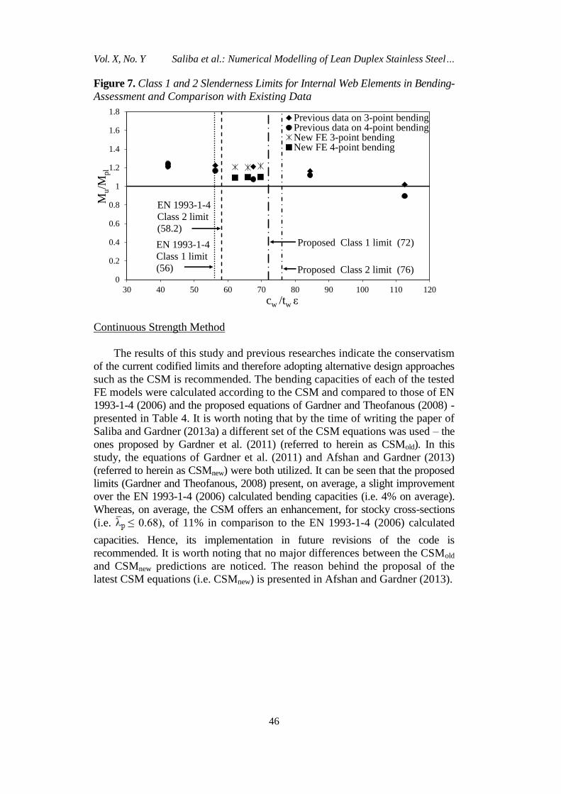
Figure 7. Class 1 and 2 Slenderness Limits for Internal Web Elements in Bending-
Assessment and Comparison with Existing Data
0
0.2
0.4
0.6
0.8
1
1.2
1.4
1.6
1.8
30 40 50 60 70 80 90 100 110 120
Mu/M
pl
cw /tw ε
Previous data on 3-point bendingPrevious data on 4-point bendingNew FE 3-point bendingNew FE 4-point bending
EN 1993-1-4
Class 2 limit
(58.2)
Proposed Class 2 limit (76)
EN 1993-1-4
Class 1 limit
(56)
Proposed Class 1 limit (72)
Continuous Strength Method
The results of this study and previous researches indicate the conservatism
of the current codified limits and therefore adopting alternative design approaches
such as the CSM is recommended. The bending capacities of each of the tested
FE models were calculated according to the CSM and compared to those of EN
1993-1-4 (2006) and the proposed equations of Gardner and Theofanous (2008) -
presented in Table 4. It is worth noting that by the time of writing the paper of
Saliba and Gardner (2013a) a different set of the CSM equations was used – the
ones proposed by Gardner et al. (2011) (referred to herein as CSMold). In this
study, the equations of Gardner et al. (2011) and Afshan and Gardner (2013)
(referred to herein as CSMnew) were both utilized. It can be seen that the proposed
limits (Gardner and Theofanous, 2008) present, on average, a slight improvement
over the EN 1993-1-4 (2006) calculated bending capacities (i.e. 4% on average).
Whereas, on average, the CSM offers an enhancement, for stocky cross-sections
(i.e. ≤ 0.68), of 11% in comparison to the EN 1993-1-4 (2006) calculated
capacities. Hence, its implementation in future revisions of the code is
recommended. It is worth noting that no major differences between the CSMold
and CSMnew predictions are noticed. The reason behind the proposal of the
latest CSM equations (i.e. CSMnew) is presented in Afshan and Gardner (2013).

Athens Journal of Technology and Engineering March 2018
47
Table 4. Summary of Bending Capacities of the FE Models Calculated according to EN 1993-1-4 (2006), Proposed Limits (Gardner and
Theofanous, 2008) and the CSM (Gardner et al., 2011; Afshan and Gardner, 2013)
Test type Cross-section EN1993-1-4/Test Proposed/Test CSMold/Test CSMnew/Test
3-point bending tests
I-180×120×6×4-1 0.70 0.75 - -
I-180×120×8×6-1 0.71 0.80 0.84 0.82
I-180×120×10×6-1 0.69 0.69 0.79 0.77
I-180×120×15×4-1 0.75 0.83 0.90 0.89
I-190×125×6×4-1 0.75 0.75 - -
I-190×125×8×6-1 0.70 0.70 0.81 0.79
I-190×125×10×6-1 0.71 0.71 0.79 0.78
I-190×125×15×4-1 0.75 0.83 0.89 0.87
I-200×130×6×4-1 0.70 0.76 - -
I-200×130×8×6-1 0.70 0.70 0.80 0.78
I-200×130×10×6-1 0.72 0.72 0.81 0.79
I-200×130×15×4-1 0.74 0.82 0.88 0.86
4-point bending tests
I-180×120×6×4-2 0.78 0.83 - -
I-180×120×8×6-2 0.78 0.88 0.92 0.90
I-180×120×10×6-2 0.75 0.75 0.85 0.84
I-180×120×15×4-2 0.82 0.91 1.00 0.98
I-190×125×6×4-2 0.74 0.81 - -
I-190×125×8×6-2 0.76 0.76 0.88 0.87
I-190×125×10×6-2 0.77 0.77 0.87 0.85
I-190×125×15×4-2 0.82 0.91 0.97 0.95
I-200×130×6×4-2 0.78 0.85 - -
I-200×130×8×6-2 0.78 0.78 0.89 0.87
I-200×130×10×6-2 0.79 0.79 0.88 0.87
I-200×130×15×4-2 0.82 0.91 0.97 0.95
Mean
0.75 0.79 0.88 0.86
COV
0.056 0.087 0.073 0.073

Vol. 5, No. 1 Saliba et al.: Numerical Modelling of Lean Duplex Stainless Steel…
48
Table 5. Summary and Comparisons of Shear Capacities Obtained from the FE Tests, EN 1993-1-4 (2006), EN 1993-1-5 (2006) and Saliba et
al. (2014) Predictions
End Post Cross-section FE VEd (kN) VEN 1993-1-4 (kN) VEN 1993-1-5 (kN) VSaliba et al. (kN) FE/EN 1993-1-4 FE/EN 1993-1-5 FE/Saliba et al.
Rigid
I-700×250×12×4-1 553 405 455 495 1.36 1.21 1.12
I-700×250×12×6-1 978 680 800 845 1.44 1.22 1.16
I-700×250×12×8-1 1528 1017 1200 1227 1.50 1.27 1.24
I-700×250×15×4-1 578 467 523 557 1.24 1.11 1.04
I-700×250×15×6-1 1007 767 879 932 1.31 1.14 1.08
I-700×250×15×8-1 1531 1115 1280 1325 1.37 1.20 1.16
I-700×250×12×4-2 469 307 353 382 1.53 1.33 1.23
I-700×250×12×6-2 869 541 658 694 1.61 1.32 1.25
I-700×250×12×8-2 1266 878 1058 1096 1.44 1.20 1.15
I-700×250×15×4-2 482 344 389 418 1.40 1.24 1.15
I-700×250×15×6-2 805 581 693 734 1.39 1.16 1.10
I-700×250×15×8-2 1273 878 1058 1096 1.45 1.20 1.16
Average 1.42 1.22 1.15
Mean 0.069 0.055 0.057
Non-rigid
I-700×250×12×4-1 509 408 377 442 1.25 1.35 1.15
I-700×250×12×6-1 906 688 713 771 1.32 1.27 1.17
I-700×250×12×8-1 1427 1017 1165 1140 1.40 1.22 1.25
I-700×250×15×4-1 545 469 444 503 1.16 1.23 1.08
I-700×250×15×6-1 1007 767 786 851 1.31 1.28 1.18
I-700×250×15×8-1 1461 1124 1252 1247 1.30 1.17 1.17
I-700×250×12×4-2 431 311 276 332 1.39 1.56 1.30
I-700×250×12×6-2 838 541 545 609 1.55 1.54 1.38
I-700×250×12×8-2 1260 878 960 995 1.43 1.31 1.27
I-700×250×15×4-2 452 345 312 366 1.31 1.45 1.23
I-700×250×15×6-2 756 588 585 656 1.29 1.29 1.15
I-700×250×15×8-2 1241 878 960 995 1.41 1.29 1.25
Average 1.34 1.33 1.22
Mean 0.075 0.093 0.065

Athens Journal of Technology and Engineering March 2018
49
Shear
A total of 24 plate girders with rigid and non-rigid end posts were
modelled. The FE models were selected to ensure shear buckling occurs in the
webs of the plate girder i.e. a pure shear failure mechanism. A typical example
of this failure mode is presented in Figure 3.
Similar to the bending tests, the results obtained from the shear FE tests
indicate a similar structural behaviour with existing experimental and numerical
data. The results indicate a higher shear capacity for rigid end post sections when
compared to the non-rigid ones (~ 5% increase); similar observations were
reported by Estrada et al. (2007b). As mentioned earlier, the end post rigidity is
not accounted for in the EN 1993-1-4 (2006) equations, and therefore may, in
some cases, lead to conservative results. Accordingly, it is recommended to
account for the end post rigidity when calculating the ultimate shear resistance
of cross-sections.
The comparisons provided in Table 5 show that, on average, the FE results
are higher than the EN 1993-1-4 (2006) predictions by 42% and 34% for rigid
and non-rigid cross-sections, respectively. Furthermore, comparisons show a mean
ratio of FE results to EN 1993-1-5 (2006) predictions of 1.22 (coefficient of
variation, COV: 0.055) and 1.33 (COV: 0.093), for rigid and non-rigid cross-
sections, respectively. Major improvements were obtained when adopting the
recently proposed equations (Saliba et al., 2014) in which the FE results are
now only higher, on average, than Saliba et al. (2014) predictions by 15% and
22% for rigid and non-rigid cross-sections, respectively. Furthermore, the
equations of Saliba et al. (2014) led to a decrease in the scatter when compared
to the codified predictions. The obtained results indicate the conservatism of
the codified calculated capacities and highlight the importance of modifying
the current stainless steel shear design equations in order to safely exploit the
full structural capacity of the cross-sections.
Conclusions
The aim of this paper is to continue the previous research carried out on
lean duplex stainless steel welded I-sections by providing additional structural
performance data, derived from finite element modelling, when tested in bending
and shear. A background on the existing codified design approaches for both
bending and shear and the latest design proposals was provided. A detailed
description of the numerical analysis adopted in the current study was presented. A
total of forty-eight cross-sections under bending and shear were numerically
simulated. The obtained results from the bending finite element tests together
with existing experimental and numerical data collected from the relevant
literature were used to assess the applicability of the codified slenderness limits
and the proposed limits of Gardner and Theofanous (2008) to lean duplex stainless
and their accuracy in predicting the bending resistance of stainless steel welded
I-sections. It was found that Eurocode 3 for stainless steel limits are conservative

Vol. 5, No. 1 Saliba et al.: Numerical Modelling of Lean Duplex Stainless Steel…
50
and better results may be achieved by adopting the proposed limits whereas the
greatest improvements were achieved by using the newly developed continuous
strength method equations. Similarly, the results obtained from the finite element
shear tests indicated that the shear design equations of Eurocode 3 for stainless
steel are overly conservative and a distinction between rigid and non-rigid end
posts is recommended. Greater improvements in the calculation of shear
resistance were achieved through Saliba et al. (2014) proposed shear equations.
The adoption of the revised slenderness limits and the recently proposed shear
design equations was suggested and the importance of embracing novel design
methods such as the continuous strength method was highlighted and
recommended. Finally, continuous investigation into the structural behaviour of
lean duplex stainless steel is encouraged to help promote its adoption in the
construction industry as an economical alternative compared to the commonly
used stainless steel grades.
References
Afshan, S. and Gardner, L. 2013. The continuous strength method for structural stainless
steel design. Thin-walled Structures. 68, 42-49.
Anbarasu, M. and Ashraf, M. 2016. Behaviour and design of cold-formed lean duplex
stainless steel lipped channel columns. Thin-walled structures. 104, 106-115.
Ashraf, M., Gardner, L. and Nethercot, D. A. (2008). Structural stainless steel design:
Resistance based on deformation capacity. Journal of Structural Engineering, ASCE.
134(3), 402-411.
Baddoo, N.R. 2008. Stainless steel in construction: A review of research, application,
challenges and opportunities. Journal of Constructional Steel Research. 64, 11,
1199-1206.
Davies, A.W. and Griffith, D.S.C. 1999. Shear strength of steel plate girders. In
Proceedings of the Institution of Civil Engineers-Structures and Buildings. 134,
147-157.
EN 10088-4. 2009. Stainless steel – Part 4: Technical delivery conditions for sheet/
plate and strip of corrosion resisting steels for general purposes. CEN.
EN 1993-1-1. 2005. Eurocode 3: Design of steel structures – Part 1.1: General rules –
General rules and rules for buildings. CEN.
EN 1993-1-4. 2006. Eurocode 3: Design of steel structures – Part 1.4: General rules –
Supplementary rules for stainless steel. CEN.
EN 1993-1-5. 2006. Eurocode 3: Design of steel structures – Part 1.5: Plated Structural
elements. CEN.
ENV 1993-1-4. 1996. Eurocode 3: Design of steel structures – Part 1.4: General rules
– Supplementary rules for stainless steel. CEN.
Estrada, I., Real, E. and Mirambell, E. 2007a. General behaviour and effect of rigid
and non-rigid end post in stainless steel plate girders loaded in shear. Part I:
Experimental study. Journal of Constructional Steel Research. 63, 7, 970-984.
Estrada, I., Real, E. and Mirambell, E. 2007b. General behaviour and effect of rigid
and non-rigid end post in stainless steel plate girders loaded in shear. Part II:
Extended numerical study and design proposal. Journal of Constructional Steel
Research. 63, 7, 985-996.

Athens Journal of Technology and Engineering March 2018
51
Gardner, L. 2005. The use of stainless steel in structures. Progress in Structural
Engineering and Materials. 7, 2, 45-55.
Gardner, L. 2008. The continuous strength method. In Proceedings of the Institution of
Civil Engineers-Structures and Buildings. 161, 3, 127-133.
Gardner, L. and Ashraf, M. (2006). Structural design for non-linear metallic materials.
Engineering Structures. 28(6), 926-934.
Gardner, L. and Theofanous, M. 2008. Discrete and continuous treatment of local
buckling in stainless steel elements. Journal of Constructional Steel Research. 64,
11, 1207-1216.
Gardner, L., Wang, F. and Liew, A. 2011. Influence of strain hardening on the behaviour
and design of steel structures. International Journal of Structural Stability and
Dynamics. 11, 5, 855-875.
Hassanein, M. 2011. Finite element investigation of shear failure of lean duplex stainless
steel plate girders. Thin-walled structures. 49, 8, 964-973.
Hibbitt, Karlsson and Sorensen, Inc. 2012. ABAQUS. ABAQUS/Standard user’s
manual volumes I-III and ABAQUS CAE manual, Version 6.12, Pawtucket, USA,
2012.
Höglund, T. 1998. Shear buckling resistance of steel and aluminium plate girder. Thin-
walled Structures. 29, 1-4, 13-30.
Huang, Y. and Young, B. 2012. Material properties of cold-formed lean duplex stainless
steel sections. Thin-walled structures. 54, 72-81.
Huang, Y. and Young, B. 2014. Structural performance of cold-formed lean duplex
stainless steel columns. Thin-walled structures. 83, 59-69.
Lecce, M. and Rasmussen, K.J.R. 2006. Distortional buckling of cold-formed stainless
steel sections: finite-element modelling and design. Journal of Structural
Engineering, ASCE. 132, 4, 505-514.
Patton, M. and Singh, K. 2012. Numerical modelling of lean duplex stainless steel
hollow columns of square, L−, T−, and + − shaped cross sections under pure axial
compression. Thin-walled structures. 53, 1-8.
Patton, M. and Singh, K. 2013. Buckling of fix-ended lean duplex stainless steel hollow
columns of square, L−, T−, and þ-shaped sections under pure axial compression -a
finite element study. Thin-walled structures. 63, 106-116.
Presta, F., Hendy, C.R. and Turco, E. 2008. Numerical validation of simplified theories
for design rules of transversely stiffened plate girders. Structural Engineering. 86,
21, 37-46.
Ramberg, W. and Osgood, W. R. (1943). Description of stress-strain curves by three
parameters. Technical Note No 902, National Advisory Committee for Aeronautics
Washington, D.C.
Sachidananda, K. and Singh, K. 2015. Numerical study of fixed ended lean duplex
stainless steel (LDSS) flat oval hollow stub column under pure axial compression.
Thin-walled structures. 96, 105-119.
Saliba, N. 2012. Structural behaviour of lean duplex stainless steel welded I-sections
[PhD thesis]. Department of Civil and Environmental Engineering, Imperial College
London, UK.
Saliba, N. and Gardner, L. 2013a. Cross-section stability of lean duplex stainless steel
welded I-sections. Journal of Constructional Steel Research. 80, 1-14.
Saliba, N. and Gardner, L. 2013b. Experimental study of the shear response of lean
duplex stainless steel plate girders. Engineering Structures. 46, 375-391.
Saliba, N., Real, E. and Gardner, L. 2014. Shear design recommendations for stainless
steel plate girders. Engineering Structures. 59, 220-228.

Vol. 5, No. 1 Saliba et al.: Numerical Modelling of Lean Duplex Stainless Steel…
52
Saliba, N. and Gardner, L. 2015. Extension of the continuous strength method to the
determination of shear resistance. In Proceedings of the 13th Nordic Steel
Construction Conference. 235-236.
Sieurin, H. and Sandström, R. and Westin, E.M. 2007. Fracture toughness of the lean
duplex stainless steel LDX 2101. Metallurgical and Material Transactions A. 37,
10, 2975-2981.
Theofanous, M. and Gardner, L. 2009. Testing and numerical modelling of lean duplex
stainless steel hollow section columns. Engineering Structures. 31, 12, 3047-3058.
Theofanous, M. and Gardner, L. 2010. Experimental and numerical studies of lean duplex
stainless steel beams. Journal of Constructional Steel Research. 66, 6, 816-825.