Numerical Modeling of Thermal Stratification in Cryogenic ... · for the design of thermal...
24
Numerical Modeling of Thermal Stratification in Cryogenic Propellant Tanks Thermal & Fluids Analysis Workshop TFAWS 2018 August 20-24, 2018 NASA Johnson Space Center Houston, TX TFAWS eCryo Paper Session Xiao-Yen Wang/NASA GRC Jonathan Harrison/Gamma Technologies Andy Noonan/Gamma Technologies Pooja Desai/NASA JSC
Transcript of Numerical Modeling of Thermal Stratification in Cryogenic ... · for the design of thermal...

Numerical Modeling of Thermal
Stratification in Cryogenic
Propellant Tanks
Thermal & Fluids Analysis Workshop
TFAWS 2018
August 20-24, 2018
NASA Johnson Space Center
Houston, TX
TFAWS eCryo Paper Session
Xiao-Yen Wang/NASA GRC
Jonathan Harrison/Gamma Technologies
Andy Noonan/Gamma Technologies
Pooja Desai/NASA JSC

Contents
• Introduction
• Cryogenic tank modeling approaches
– CFD versus engineering approach
• SHIIVER tank modeling
– Thermal Desktop (TD) versus GT-suite
• Stratification modeling validation
– GT-suite versus Daigle’s Matlab code:
• “Temperature stratification in Cryogenic Fuel tank”, Matthew
Daigle, NASA Ames Research Center, Journal of Thermophysics
and heat transfer, Vol 27, No. 1, January-March 2013
– Spherical LOX tank modeling
• TD 2 nodes model
• GT 2 nodes model
• GT 20 nodes model
• ConclusionsTFAWS 2018 –August 20-24, 20188/15/2018 2

Introduction
• The boiling-off rate of cryogenic propellant inside the
tank is always one of the major factors to be considered
for the design of thermal insulation around the propellant
tank and space launch system.
• Thermal stratification inside the tank is important to be
included in the model for an accurate prediction of the
boiling-off rate for different thermal insulation systems of
propellant tanks.
• Numerical modeling of thermal stratification can be full-
scale computational fluid dynamics (CFD) analysis or
engineering modeling tool using lumped-parameter
method.
TFAWS 2018 –August 20-24, 20188/15/2018 3
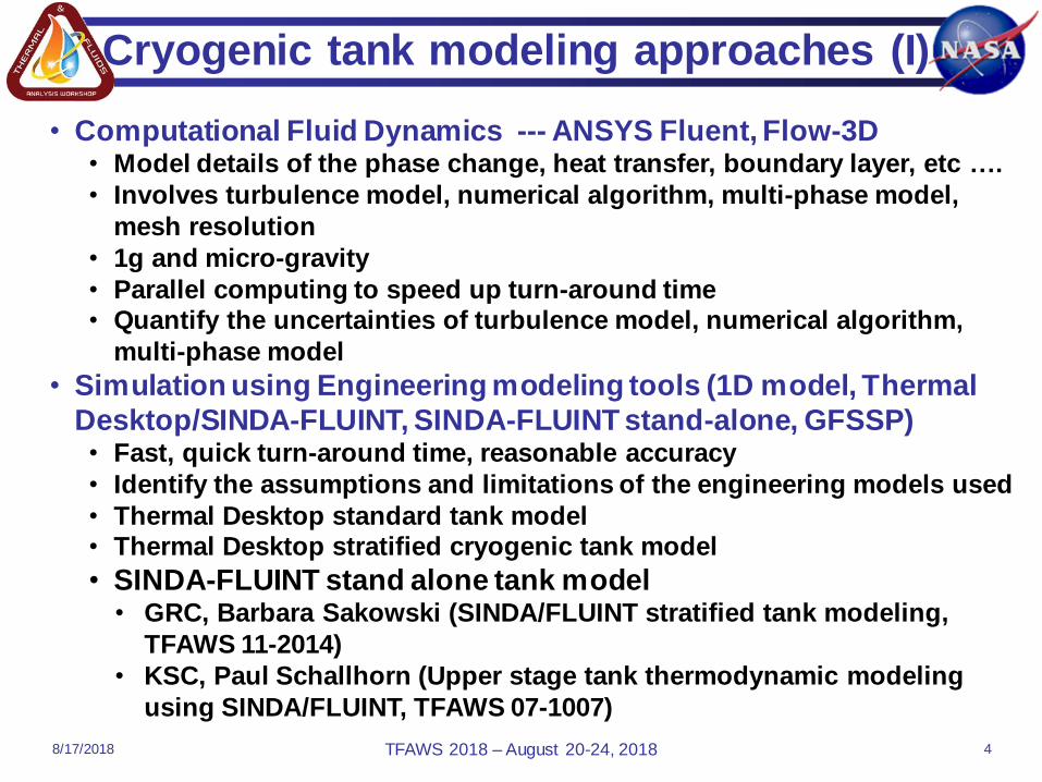
• Computational Fluid Dynamics --- ANSYS Fluent, Flow-3D• Model details of the phase change, heat transfer, boundary layer, etc ….
• Involves turbulence model, numerical algorithm, multi-phase model,
mesh resolution
• 1g and micro-gravity
• Parallel computing to speed up turn-around time• Quantify the uncertainties of turbulence model, numerical algorithm,
multi-phase model
• Simulation using Engineering modeling tools (1D model, Thermal
Desktop/SINDA-FLUINT, SINDA-FLUINT stand-alone, GFSSP)• Fast, quick turn-around time, reasonable accuracy
• Identify the assumptions and limitations of the engineering models used
• Thermal Desktop standard tank model• Thermal Desktop stratified cryogenic tank model
• SINDA-FLUINT stand alone tank model • GRC, Barbara Sakowski (SINDA/FLUINT stratified tank modeling,
TFAWS 11-2014)
• KSC, Paul Schallhorn (Upper stage tank thermodynamic modeling
using SINDA/FLUINT, TFAWS 07-1007)
Cryogenic tank modeling approaches (I)
TFAWS 2018 –August 20-24, 20188/17/2018 4

Thermal Desktop/SINDA-FLUINT tank models:
1. Standard way: one node for the vapor region and one node for
the liquid region to model the cryogenic fluids inside the tank,
the phase change, heat transfer and mass transfer between the
liquid and vapor.
2. Stratified cryogenic tank model:
The tank has to be cylindrical. The logic coding has to change if
it is not a cylindrical tank. The tank only has nodes along the
height. The junction lumps are manually connected to the tank
lumps one by one.
GT-SUITE:
• Uses similar approach and provides an interface which
allows users to utilize multiple nodes for the fluids then
couple the fluids to the thermal nodes on the
solids/structure (radiation, conduction and convection)
• First cut effort to explore an option for tank stratification
modelingTFAWS 2018 –August 20-24, 2018
Cryogenic tank Engineering modeling approach
8/15/2018 5

Background of SHIIVER tank modeling
• The Structural Heat Intercept, Insulation, and
Vibration Evaluation Rig (SHIIVER) consists
of a large cryogenic tank assembly with
geometry, support structure, skirt and fluid
penetrations comparable to an actual space
flight vehicle configuration, such as EUS
LH2 tank.
• SHIIVER will be used to investigate three
main areas:
– structural cooling using tank boil off
vapor to intercept conductive heat leak
– design, construction, and performance
of MLI on a large flight tank
configuration
– MLI blanket durability under launch
acoustic vibration conditions
TFAWS 2018 –August 20-24, 2018
skirt
tank
8/15/2018 6

• Geometry includes tank (FWD
dome, barrel, AFT dome), FWD
skirt and AFT skirt, vapor
cooling tubes on FWD skirt, FWD
flange, AFT flange
• Inside the tank: use twin lump to
model the convection and phase
change and pressure of the
fluids
• Pressure control of the tank: use
PID controller
• Heater control: use logic to turn
on or off the heaters, heater are
on FWD dome
• Heater power: define as a
register to vary the power
Thermal Desktop (TD) SHIIVER Tank Model
TFAWS 2018 –August 20-24, 2018
FWD Skirt
FWD Dome
FWD flange
Tank barrel
AFT flange
AFT Dome
AFT Skirt
heaters
8/15/2018 7

Case run for SHIIVER tank model
– Initial conditions:
• Tank pressure = 2e5 Pa
• Vapor temperature = 25 K
• Liquid temperature = 20 K
• Skirt wall temperature = 293 K
• Tank wall temperature = 20 K
– 33% ullage GH2
– Environment: 293 K, radiation only
– No venting
– Heaters are OFF
– Vapor cooling is OFF
– Transient run to 5400 s (1.5 hr)
– Both TD and GT-suite run the same case
TFAWS 2018 –August 20-24, 2018
t = 0
8/15/2018 8

SHIIVER Tank TD model Results
TFAWS 2018 –August 20-24, 2018
SHIIVER tank assembly
(plotted with SOFI on the tank)
Temperature Contours
tank alone
(plotted without SOFI)
8/15/2018 9

GT-suite Model for SHIIVER tank
2. Create FE mesh on FWD skirt, FWD
flange, FWD dome, tank barrel, AFT skirt,
AFT dome, and AFT flange and AFT skirt1. Discretize the fluid volume
into 20 subvolumes
3. Build thermal ports between tank walls to fluids for fluid-thermal interaction
4. Thermal ports between the thermal structure (contact resistance)
5. Boundary condition between thermal structure to the ambient (radiation)
TFAWS 2018 –August 20-24, 20188/15/2018 10

Schematics of GT-suite SHIIVER tank model
Schematics of GT-suite model
• Ports in red
subject to
radiation at 293K
• Green ports on
skirt are
adiabatic
TFAWS 2018 –August 20-24, 20188/15/2018 11

• Tank Wall Temperatures @ 5400sec– The temperature is more in line with the TD result, though with more
pronounced stratification as expected since there are more discretized
fluid volumes
Thermal Desktop Result
*Gray color indicates temperature above or below color scale
TFAWS 2018 –August 20-24, 2018
SHIIVER tank model results comparison
TD GT-suite
8/15/2018 12

SHIIVER tank model results comparison
• Fluid temperature– there is significant thermal stratification, liquid temps are higher than the TD
liquid temp, while gas temps are for the most part lower than TD gas temp
TFAWS 2018 –August 20-24, 2018
Liquid
vapor
vapor
Liquid
8/15/2018 13

• LH2 Boiled Off– GT shows that there is a
significant amount of boil off
of the bulk liquid than the TD
predicts.
TFAWS 2018 –August 20-24, 2018
SHIIVER tank model results comparison
• Fluid pressure• the pressure more closely
matches the TD result
8/15/2018 14

Summary of SHIIVER tank models
• There are discrepancies between TD twin lump model
and GT-suite 20 node model.
• Major factors can be contributed to the discrepancies:
– How the heat transfer coefficients are computed
– How the interface of vapor and liquid is modeled
– Boundary layer effect
– Material and fluid properties
– 2 nodes versus 20 nodes for the fluid
• Need to validate the stratification effects predicted by
GT-suite SHIIVER tank model.
TFAWS 2018 –August 20-24, 20188/15/2018 15

Validation of tank stratification
• Work on Daigle’s cases for stratification validation
• Quantify the effect of the stratification effects:
– A simple spherical LOX tank:
• TD 2 nodes versus GT-suite 2 nodes
• GT-suite 2 nodes versus GT-suite 20 nodes
TFAWS 2018 –August 20-24, 20188/15/2018 16

Tank in storage without ventingDaigle GT
Stratification modeling validation: Daigle’s case
TFAWS 2018 –August 20-24, 2018
• The cylindrical tank is similar to that of space shuttle ET• Radius of the tank is 4.28 m and the height is 30 m.• Tank has 50/50 liquid/ullage ratio• Liquid is LH2, Vapor is mixture of GH2/GHe• Heat from environment to the tank is 10 kw • No venting• Transient run to 5000 s• GT-suite follows the details on modeling the stratification, however
Boundary layer effect is not included yet, slight difference in vapor and fluid interface treatment.
8/15/2018 17

Tank in storage without venting
GT
GT-suite
Daigle
TFAWS 2018 –August 20-24, 2018
• GT results show the similar trend as Daigle
• GT Results of boiling off roughly 2x as much as Daigle
• Top and bottom of the tank are hotter than Daigle’s results
• Boundary layer effect is a key factor.
• Need more investigation to get better agreement. 8/17/2018 18

• Radius of sphere: 23 inches (0.5842 m)
• Tank wall material: SS 304
• Thickness of wall: 0.25 inches (0.00635 m)
• Tank wall temp: 96.0 K
• Liquid prop temp: 95.0 K
• Vapor temp: 96.0 K
• Void (ullage) fraction: 50%
• Pressure: 25 psia ( 172330 pascal)
• Ambient condition: 293 K, vacuum, radiation only
• TD model with twin lump
• GT-suite model with twin lump
• GT-suite with 20 nodes for the fluids
Stratification modeling validation: spherical LOX tank
TFAWS 2018 –August 20-24, 20188/15/2018 19

Spherical LOX tank: Ullage Temperature
• All three models show similar trend, though the GT 20 volume model with
mass averaged temperature over all 10 ullage volumes is the coldest over
time
• Significant thermal stratification is shown in the ullage volume
• GT 20 nodes model shows a warmer bottom, due to high
surface volume ratio
• With Boundary layer effect, this might not happen Wall temp
at 7000sec
TFAWS 2018 –August 20-24, 20188/15/2018 20

Spherical LOX tank: Liquid Temperature
• All three models show similar trend
• The 20 node model shows significant thermal gradient
in the liquid region
Wall temp
at 7000sec
TFAWS 2018 –August 20-24, 20188/15/2018 21

Spherical LOX tank: Tank Pressure
• GT 2 node model shows very similar trend as Thermal
Desktop 2 node model
• GT 20 node model shows a higher trend
8/15/2018 TFAWS 2018 –August 20-24, 2018 22

Conclusions
TFAWS 2018 –August 20-24, 2018
• SHIIVER tank model efforts have been presented
− TD thermal model with twin lump for the fluids
− GT-suite model with 20 nodes for the fluids
− Attempt to address the thermal stratification effect to
get a more accurate boiling-off rate and vapor
temperature near the venting line
• Tank stratification modeling first cut efforts have been
presented. It is a work in progress and aims to provide
users an option to explore.
− Daigle’s case is modeled using GT-suite to validate the
details of stratification physics.
− A simple spherical LOX tank model results are
compared between 1) TD with twin lump, 2) GT-suite
with 2 nodes and 20 nodes for the fluids.
8/15/2018 23

Acknowledgements
TFAWS 2018 –August 20-24, 2018
• Great appreciations go to tech support at C&R tech,
valuable help from David Johnson and Mark Welch;
Barbara Sakowski and Robert Buehrle at GRC for
reviewing the charts; NASA GRC eCryo project for
funding this work.
8/15/2018 24