Numerical Modeling of Microelectrochemical...
131
General rights Copyright and moral rights for the publications made accessible in the public portal are retained by the authors and/or other copyright owners and it is a condition of accessing publications that users recognise and abide by the legal requirements associated with these rights. • Users may download and print one copy of any publication from the public portal for the purpose of private study or research. • You may not further distribute the material or use it for any profit-making activity or commercial gain • You may freely distribute the URL identifying the publication in the public portal If you believe that this document breaches copyright please contact us providing details, and we will remove access to the work immediately and investigate your claim. Downloaded from orbit.dtu.dk on: Aug 28, 2018 Numerical Modeling of Microelectrochemical Systems Adesokan, Bolaji James; Evgrafov, Anton ; Sørensen, Mads Peter Publication date: 2015 Document Version Publisher's PDF, also known as Version of record Link back to DTU Orbit Citation (APA): Adesokan, B. J., Evgrafov, A., & Sørensen, M. P. (2015). Numerical Modeling of Microelectrochemical Systems. Kgs. Lyngby: Technical University of Denmark (DTU). (DTU Compute PHD-2015; No. 362).
Transcript of Numerical Modeling of Microelectrochemical...
General rights Copyright and moral rights for the publications made accessible in the public portal are retained by the authors and/or other copyright owners and it is a condition of accessing publications that users recognise and abide by the legal requirements associated with these rights.
• Users may download and print one copy of any publication from the public portal for the purpose of private study or research. • You may not further distribute the material or use it for any profit-making activity or commercial gain • You may freely distribute the URL identifying the publication in the public portal
If you believe that this document breaches copyright please contact us providing details, and we will remove access to the work immediately and investigate your claim.
Downloaded from orbit.dtu.dk on: Aug 28, 2018
Numerical Modeling of Microelectrochemical Systems
Adesokan, Bolaji James; Evgrafov, Anton ; Sørensen, Mads Peter
Publication date:2015
Document VersionPublisher's PDF, also known as Version of record
Link back to DTU Orbit
Citation (APA):Adesokan, B. J., Evgrafov, A., & Sørensen, M. P. (2015). Numerical Modeling of Microelectrochemical Systems.Kgs. Lyngby: Technical University of Denmark (DTU). (DTU Compute PHD-2015; No. 362).

Numerical Modeling ofMicroelectrochemical Systems
Bolaji James Adesokan
Kongens Lyngby, January, 2015DTU Compute - PhD-2015-362

Department of Applied Mathematics and Computer ScienceTechnical University of DenmarkRichard Petersens Plads, Building 324DK-2800 Kongens Lyngby, DenmarkPhone +45 4525 3031Fax+45 4588 [email protected] DTU Compute-PhD-2015-362

Preface
This thesis was prepared at the department of Applied Mathematics and Com-puter Science, Technical University of Denmark in partial fulfilment of the re-quirements for acquiring a PhD degree. The project was funded by the VillumKann Rasmussen centre of Excellence: Nano Mechanical Sensors and Actuators,fundamentals and new directions (NAMEC), and was supervised by AssociateProfessor Anton Evgrafov (DTU Compute) and co-supervised by Professor MadsPeters Sørensen (DTU Compute).
The following are one article and two manuscripts that result from the PhDresearch.
1. Bolaji James Adesokan, Anton Evgrafov and Mads Peter Sørensen, Sim-ulating cyclic voltammetry under advection for electrochemical cantilevers.Journal of Mathematical Methods in Applied Sciences.DOI: 10.1002/mma.3336(Published), 2015.
2. Bolaji James Adesokan, Xuelin Quan, Anton Evgrafov, Arto Heiskanen,Anja Boisen and Mads Peter Sørensen, Experimentation and NumericalModeling of Cyclic Voltammetry for Electrochemical Micro-sized Sensors un-der the Influence of Electrolyte Flow. Elecrochimica Acta. (submitted)
3. Bolaji James Adesokan, Anton Evgrafov and Mads Peter Sørensen, Tran-sient dynamics of electric double layer (EDL) characterized by charge transferand steric effect. (final stage of preparation)
Furthermore, a conference paper was published during the course of the PhDstudy

ii Preface
• Bolaji James Adesokan, Xuelin Quan, Anton Evgrafov, Arto Heiskanen,Anja Boisen and Mads Peter Sørensen, Hydrodynamics studies of cyclicvoltammetry for electrochemical micro biosensors. J. Phys. Conf. Ser. 574012008, 2015.
I have given the following talks during my three years’ research:
• Mathematical Modeling and Optimization of Nano-Mechanical Devices,NAMEC meeting, April 02, 2012.
• Cyclic Voltametry in Biosensors, oral presentation, BIT circus, May 15,2012.
• Modeling Cyclic Voltammetry for Nanomechanical Biosensors Studies,NAMEC meeting, January 03, 2013.
• Electromechanical Coupling towards Nanomechanical Sensors, NAMECmeeting, June 25, 2013.
• Nanomechanical Cantilever Biosensors - a mathematical view, oral pre-sentation, ITMAN Seminar Series, March 07, 2014.
• Hydrodynamics studies of cyclic voltammetry for electrochemical microbiosensors, 3rd International Conference on Mathematical Modeling inPhysical Sciences, August 28-31, 2014.
Lyngby, 31-January-2015
Bolaji James Adesokan

Summary (English)
The PhD dissertation is concerned with mathematical modeling and simula-tion of electrochemical systems. The first three chapters of the thesis consistof the introductory part, the model development chapter and the chapter onthe summary of the main results. The remaining three chapters report threeindependent papers and manuscripts.
As a preliminary to the study, we describe a general model for electrochemi-cal systems and study their underlying mechanisms through electroanalyticaltechniques. We then extend the model to a more realistic model for microelec-trochemical systems which incorporates the finite size of ionic species in thetransport equation. The model presents more appropriate boundary conditionswhich describe the modified Butler-Volmer reaction kinetics and account forthe surface capacitance of the thin electric double layer. We also have foundanalytical solution for the reactants in the bulk electrolyte that are travelingwaves.
The first paper presents the mathematical model which describes an electro-chemical system and simulates an electroanalytical technique called cyclic voltam-metry. The model is governed by a system of advection–diffusion equations witha nonlinear reaction term at the boundary. We investigate the effect of flowrates, scan rates, and concentration on the cyclic voltammetry. We establishthat high flow rates lead to the reduced hysteresis in the cyclic voltammetrycurves and increasing scan rates lead to more pronounced current peaks. Thefinal part of the paper shows that the response current in a cyclic voltammetryincreases proportionally to the electrolyte concentration.

iv Summary (English)
In the second paper we present an experiment of an electrochemical system ina microfluidc system and compare the result to the numerical solutions. Weinvestigate how the position of the electrodes in the system affects the recordedcyclic voltammetry. The result shows that convection influences the chargetransfer dynamics on the electrode surface and hence the cyclic voltammetryrecorded. In terms of relative high flow to scan rates, the current response isdominated by the convection due to the fresh supply of reactants towards theelectrode surface and quick removal of the products. We also establish that athigh scan rates and modest flow rates, peak currents are recorded. Finally, theresults show that the position of the electrodes is critical when performing cyclicvoltammetry under the flow condition. The numerical results show promisingagreement with experimental findings which could be critical in designing highlysensitive electrochemical systems.
The last paper explores the numerical solution which describes the non-lineartransient responses to a large applied potential at the electrode in a microelec-trochemical system. In our analysis, we account for the finite size properties ofions in the mass and the charge transport of ionic species in an electrochemicalsystem. This term characterizes the saturation of the ionic species close to theelectrode surface. We then analyse the responses of the system on the chargingof the electric double layer. We consider an arbitrary electrolyte solution thatis sandwiched between electrodes and allow for electrochemical reactions at theelectrode/electrolyte interface. One of the electrodes is biased with a potentialwhich triggers the reaction and the dynamics of the system. We establish thatthere is a quick build up of boundary layers in the double layer, but the finitesize constraint on the ionic species prevents overcrowding of the ionic species.The result also shows that reactants which undergo charge transfer at the elec-trode/electrolyte interface crowded the electric double layer and the dynamicsof the electric double layer is controlled by the charge transfer.

Summary (Danish)
Emnet for denne PhD afhandling er studiet af elektrokemiske mikrofluid syste-mer, hvor elektroderne består af mikrobjælker. Fokus er rettet mod indflydelsenaf fluid flow på de elektrokemiske processer samt indflydelsen af ultrahøje ionkoncentrationer tæt på elektroderne. Den videnskabelige metode er baseret påmatematisk modellering samt simulering på computer, men i nært samarbejdemed eksperimental fysikere. Afhandlingen er organiseret i 6 kapitler hvoraf de treførste består af en indledning, en udledning af den matematiske model samt etkapitel med simuleringer og resultater. Herefter følger tre kapitler indeholdendeen publiceret artikel og to øvrige manuskripter.
Modellen er baseret på Nernst Planck ligningen, som er en partiel differenti-alligning for ion koncentrationen i en elektrolyt, hvor transport af ioner indgårforårsaget af diffusion, elektriske felt gradienter og fluid flow. Randbetingelsernebeskriver de kemiske reaktioner og elektriske ladningsudvekslinger på mikrobjæl-ke elektroderne. Mere specifikt benyttes en modificeret version af Butler-Volmerreaktions kinetic ved elektroderne samt inkorporerer overflade kapacitans for-årsaget af det tynde elektriske dobbelt lag. Butler-Volmer randbetingelserne erulineære så systemet som helhed er ikke-lineært. Det elektriske felt styres af Po-ison ligningen for det elektriske potentiale. Poison ligningen og Nernst Planckligningen er koblet. Fluid flowet i den givne geometri beregnes fra Navier-Stokesligninger.
I afhandlingen simuleres en elektrokemisk analyse metode kaldet cyklisk voltam-metri. I denne metode måles strømmen gennem elektrolytten som funktion afen påført tidsperiodisk elektrisk spænding. Den periodiske spænding har "sav-tak-form, det vil sige den er sammensat af stykkevis lineære funktioner. I den
vi Summary (Danish)
første artikel undersøges effekten af fluid flow hastigheden, skanfrekvenser, ogkoncentrations variationer på cyklisk voltammetri. Cyklisk voltammetri udviserhysterese og det er vist at hysteresløjfen reduceres ved høje fluid hastigheder.Høje scanfrekvenser fører til mere udprægede strøm toppe. Simuleringer viser atstrøm responsen i cyclisk voltammetri er proportional med ion concentrationen.
De simulerede cycklisk voltammetri kurver for en mikrofluid elektrokemisk cellemed mikro bjælker som elektroder er blevet direkte sammenholdt med eksperi-mentelle resultater. Med passende estimation af parametre og modelopbygninger der opnået rigtig fornuft overensstemmelse mellem computer simuleringer ogmålinger. Resultaterne viser at konvektion har indflydelse på ladningsudvekslingved elektroderne i den strømmende fluid og dermed på strøm-spændingskurvernei cyklisk voltammetri. Ved relative høje flow hastigheder i forhold til scanfre-kvenser er strøm responsen domineret af konvektion på grund af tilførsel af nyereaktanter på elektrode overfladen samt hurtig fjernelse af reaktions produkter-ne. Placeringen af mikrobjælke elektroderne i fluid strømmen spiller ligeledes envæsentlig rolle for cyklisk voltammetri.
I sidste kapitel i afhandlingen studeres effekten af ionernes endelig størrelse foropbygning af ion koncentrationen ved mikrobjælke elektroderne. Såfremt manikke tager hensyn til ion størrelsen divergerer ion koncentrationen ved elektro-derne under påvirkning af store spændinger. For at undgå denne singularitetindføres en concentrations afhængig diffusionskonstant i Nernst Planck lignin-generne. Denne ikke-lineære diffusionkonstant er faktisk singulær ved mætningsconcentrationen, som opstår når ionenerne er pakket helt sammen og er i kon-takt med hinanden. Denne situation svarer til uendelig ionstrøms hastighed.Dette lyder som et paradoks, men det ikke-lineære diffusionsled i Nernst Planckligningenen regulariserer koncentrationen ved elektroderne således at den ikkeoverskrider koncentrationen for tættest pakkede ioner. Simuleringer viser at detikke-lineære diffusionsled føre til dannelse af kink formede randlag i ionkoncen-trationen. Det er også vist analytisk at for simple tilfælde med ladningsneutrali-tet eksistere ikke-lineære løbende bølgerløsninger af ion koncentrationen, analogttil shockbølger og solitoner.

Acknowledgements
First, I would like to thank my supervisors Associate Professor Anton Evgrafovand Professor Mads Peter Sørensen for their support and immense commitmentto the project and for their patient in sharing their knowledge for the completionof my studies. I am very grateful for their effort and guidance that was put intothis project. Thank you very much.
This work was supported by the Villum Kann Rasmussen centre of Excel-lence: Nano Mechanical Sensors and Actuators, fundamentals and new direc-tions (NAMEC). I am indeed grateful for their financial support that I havereceived.
I am indebted to all the people who have made this work a success, especially mycolleague Xuelin Quan from DTU Nanotech for her support in carrying out theexperiments. I am also very grateful to Associate Professor Arto Heiskanen ofDTU Nanotech for your patience and your guidance in electrochemistry whichI was a novice at the start of the thesis. I would also like to say a big thankyou to Professor Yuri Gaididei for your interesting and inspiring conversationwhenever you visit DTU Compute.
This work would not have been a success if not for the moral support of somewonderful people that I met in Copenhagen. This list is long, but I wouldlike to specially mention Øistein Wind-Willassen who made me settled in at thedepartment, the IFS at DTU, Yemi and Chichi, Adebowale and Bimpe, Solomonand Lucy, Sunday and Miriam. Thank you for your great help. I would alsolike to thank my friends Kayode and Moyosore Imole from the Netherlands andof course Austin and Adaora Ezejiofor from Germany. My sincere gratitude

viii Acknowledgements
also my colleagues from Copenhagen Christian Centre; John, Allan and Greg.Thank you for your prayers.
I would like to specially thank my wonderful wife Mary Oluwafunke and ourspecial children Ayomide and Oluwaseyi for their care and endless support. Tomy parents Eyinade and Alice Adesokan, and my brother Adewale and sistersMojirayo and Odunayo, I say a big thank you. I am also indebted to my secondparents, Samuel and Grace Matesun, thank you for always been there. Lastly, Iam eternally grateful to God for giving me the opportunity to pursue this PhDdegree.

ix

x Contents

Contents
Preface i
Summary (English) iii
Summary (Danish) v
Acknowledgements vii
1 Introduction 11.1 Thesis Structure . . . . . . . . . . . . . . . . . . . . . . . . . . . 5
2 Mathematical Modeling of Electrochemical Systems 72.1 Electrochemical Systems: concepts and components . . . . . . . 7
2.1.1 Electrodes . . . . . . . . . . . . . . . . . . . . . . . . . . . 82.1.2 Electrolyte . . . . . . . . . . . . . . . . . . . . . . . . . . 102.1.3 External wires . . . . . . . . . . . . . . . . . . . . . . . . 10
2.2 Electrode reaction and kinetics of electron transfer . . . . . . . . 102.3 Mass transfer . . . . . . . . . . . . . . . . . . . . . . . . . . . . . 15
2.3.1 Mass and charge conservation . . . . . . . . . . . . . . . . 182.3.2 Boundary conditions . . . . . . . . . . . . . . . . . . . . . 20
2.4 Electroanalytical techniques . . . . . . . . . . . . . . . . . . . . . 212.5 Finite size ion and electric double layer (EDL) . . . . . . . . . . 23
3 Summary of main results 273.1 Contributions of the thesis . . . . . . . . . . . . . . . . . . . . . . 41
4 Numerical modeling of Electroanalytical techniques 43

xii CONTENTS
5 Experimentation and Numerical Modeling of Cyclic Voltamme-try 53
6 Assessing electric double layer of microelectrochemical system 81
7 Conclusion and Outlook 95
A Appendix 99A.1 Dimensional analysis for the model equation . . . . . . . . . . . . 99
A.1.1 Boundary Conditions . . . . . . . . . . . . . . . . . . . . 100A.2 Dimensionless equations . . . . . . . . . . . . . . . . . . . . . . . 101
A.2.1 Dimensionless Ion flux B.C . . . . . . . . . . . . . . . . . 102A.2.2 Dimensionless Poisson B.C . . . . . . . . . . . . . . . . . 104
A.3 The model and the boundary conditions . . . . . . . . . . . . . . 104
Bibliography 107

Chapter 1
Introduction
Electrochemical systems are all around us. They have become indispensable andfound widespread applications in industrial processes such as oil drilling and oilrefining, corrosion industry, waste water treatment, toxic gas monitoring, med-ical applications - implantable electrochemical systems for monitoring diabeticpatients. Electrochemical systems are also present in biochemical environmentsas well as in systems such as automobile emission control, microchips, lab onchips, electro analytical devices, and airplanes. They are also found in electronicdevices that have become part of our everyday life; for example the batteriesthat power our gadgets like mobile phones, laptops and tablets, are electrochem-ical systems. Another electrochemical system that is gaining pace in popularityis the fuel cell for generating alternative energy. The list is inexhaustible.
A quick search of electrochemical systems on Google Scholar takes about 0.08secsand results in over a million articles on the subject. So why are we interested ina vastly studied subject? The study of electrochemical systems is still very rel-evant and keeps expanding due to its vast area of applications, especially sincethe effort for miniaturisation of electrochemical devices started about forty yearsago [1]. In this thesis, we shall study the mathematical modeling and analysisof microelectrochemical systems and its reactions.
An electrochemical system is a system that comprises of electrodes and an elec-trolyte solution by which one form of energy is converted to another, typically, a

2 Introduction
chemical energy is converted to electrical energy and vice versa. The electrodescan be of any type and shape but mostly they are conductors or semi conduc-tors either in solid or liquid form, for example, carbon rod - graphite, copperwire, nickel rod, silicon rod, zinc rod, mercury, amalgams etc. The electrolytecan come in form of a liquid solution in which soluble ions are present e.g.Na+, Cl−, H+. They can also occur in form of fused salts, solid electrolytesand conductive polymers, e.g. molten NaCl-KCl eutectic, sodium β-alumina,Nafion [2].
Alessandro Volta’s famous invention of Voltaic pile in the1800s which results in electricity was the first electrochem-ical system reported. However, the foundation of the mod-ern understanding of the electrochemical systems startedwith Michael Faraday’s famous experiment on electrolysisin the 1830s. He famously developed quantitative lawswhich relate the amount of electricity produced in an elec-
trochemical system to the amount of the transformed chemical substances.Around 1880, Nernst and Planck [3, 4] developed the mathematical model of aworking electrochemical system where they describe the system as a stream ofthe ionic species controlled by diffusion, migration and convection. Their modelresults in the systems of differential equations of elliptic and parabolic type.This model is termed Poisson-Nernst-Planck equation (PNP).
The rapid progress in electrochemical technologies in the earlytwentieth century triggered the development of experimentaldesigns and the theory governing the electrochemical system.Over the years, there have been many reviews reporting theadvancement of the studies of electrochemical systems. Theanalysis of electrochemical systems has been examined in text-books [5, 6, 7, 2, 8, 9, 10], reviews and several journal publica-tions. Bard et al and Newmann et al [2, 8] gave a comprehensive and thoroughanalysis of the subject. Leddy et al [11] provides a review of historical per-spectives on the topic while Bard et al and Volgin et al [12, 13] present recentreviews on the subject where they briefly introduce the history of the topic andpresent a review of earlier publications on the subject while focusing primarilyon the applications of electrochemical systems in different fields. Prentice etal [14] surveyed early publications on the numerical aspects of the subject inwhich they detailed comprehensive collections of methods and examined criticalanalysis of both the numerical and the electrochemical aspects of the subject.In addition, Schlesinger et al [15] has also provided a recent review that focusesmainly on the numerical techniques.
By the mid 20th century, the theory describing the mass transfer process ofstreams of ions in an electrochemical system was well developed. Typically, the

3
migration term in the commonly used Nernst-Planck model allows one to deter-mine the distribution of the electrical potential which requires solving Poisson’sequation that relates the electric field to the space charge density. Generally, thecharge density is set to zero, which is referred to as the electroneutrality condi-tion. This condition significantly simplifies solving the Nernst-Planck equationsand the corresponding distribution of the electrical potential. However, suchapproximation is only applicable to systems characterized by the dimension ofan electrochemical system far greater than that of the space charge density.Such a system is termed a macro electrochemical system.
Around 1980s, miniaturized electrochemical systems became available and starteda billion dollar industry of micro electroanalytical devices [16, 17, 18] especiallyin the biosensor industry. Micro/nano electrochemical systems come with greatadvantages and have led to new technologies and methodologies. One of theadvantages of such systems is the decrease in ohmic potential drop across theelectrolyte. Another advantage is the formation of fast steady state signals aswell as the increase in the measured current as a result of enhanced mass trans-port at the electrode surface. In addition, there is an increase in the signal tonoise ratio in a micro electrochemical system. This is essential in the designof highly sensitive electrochemical sensors. Furthermore, micro electrochemicalsystems have the advantage of recording high current densities and abilities tomeasure currents and charges in micro/nano amperes. Nevertheless, the math-ematical treatment of analysis of such systems differs from that of a macrosystem.
For microelectrochemical systems the electrode-electrolyte interface plays a cru-cial role and consequently limits to what extent the simplified models for macrosystems can be applied. For example, if a potential of more than 50mV is ap-plied to an electrode in a microelectrochemical system, the ionic concentrationis usually overestimated by the theory [19, 20]. One of the reasons for thisfeature is the fact that ionic species are treated as point charges and the finitesize of ions is discarded as in macro systems. This assumption becomes invalidbecause close to the electrode surface the ion concentration can get very highdue to the crowding effect and electroneutrality breaks down in this region. Asa consequence, the ion transport model should account for the finite size ofions and the model must be coupled to appropriate boundary conditions whichincorporate the region where electroneutrality breaks down. Furthermore, inmodeling microelectrochemical systems the surface charge density cannot beset to zero which means that Poisson’s equation couples directly to the Nernst-Planck equation through the concentration field. In addition, the presence of avery small coefficient in the highest derivative of the Poisson’s equation in a mi-croelectrochemical system introduces boundary layers, which makes the problemmathematically challenging both numerically and analytically.
4 Introduction
The model for a microelectrochemical system divides the ionic streams in theelectrolyte solution into two regions, namely the electroneutral bulk region (asin the macro model) far away from the electrode and the electric double layer(EDL), a region adjacent to the electrode. The electric double layer is a set ofnested layers, which consists of the inner compact layer referred to as the Sternlayer, and the outer diffuse layer also known as the Debye layer. The typicalwidth of an EDL is about 1-10Å depending on the electrolyte solution. Withinthe electric double layer there is usually no net charge separation which meansthat one or more ionic species can occur in excess and hence electroneutralitycondition does not hold in this region. Typically, the Stern layer of the doublelayer is considered to be the compact layer where ions adhere to the surface of theelectrodes and a capacitive effect of the ions within the compact layer is includedwhile formulating the appropriate boundary conditions. The most importantwork on the Stern layer was performed both theoretically and experimentallyby Stern and Grahame, respectively [21, 22]. On the other hand, the Debyelayer is the region where the diffuse-charge effect of the ionic species is normallyaccounted for. In addition, the dynamical charging of the layer is considered tohave essential effect on the charge transfer kinetics at the electrode-electrolyteinterface.
Numerous authors have attempted to incorporate models for the electric doublelayer in modeling of ion and charge transport in a microelectrochemical sys-tem. Bazant et al and Chu et al [23, 24] have considered steady state transportmodel and studied the diffuse charge effect in the electric double layer. Theyadopted the classical Poisson-Nernst-Planck equations for a binary and symmet-ric electrolyte but neglect the steric effect due to the finite size of ions. Theirmodel is suitable for the dilute electrolyte solution. Time dependent transportmodels have also been studied in [25, 26, 27] for a binary and symmetric elec-trolyte albeit without taking the steric effect into account. These models havebeen extended by Bazant et al, Kilic et al and Olsen et al [28, 29, 30] to inves-tigate concentrated electrolyte under large applied potential while accountingfor the finite size effect of the ions. In their studies, they solved the modifiedPoisson-Nernst-Planck equations that is valid for binary and symmetric elec-trolytes which is characterized by large potentials. The authors included anextra term in the chemical potential and mass flux to account for the finite sizeof ionic species. Furthermore, in their model they have prescribed blocked elec-trode boundary conditions which means there are no electrochemical reactionsat the electrodes.
In many practical applications, ionic charges of higher valence are present inan electrochemical system. For example, the human blood plasma containshigh concentration of Na+, Ca2+, Mg2+, Cl−, HCO−
3 , HPO2−3 , SO2−
4 .It is therefore essential to model electrochemical systems in a general sense ofarbitrary valence charges. In addition, in most realistic electrochemical systems,

1.1 Thesis Structure 5
reactions on electrode surfaces allow for passage of a current, which means thatthe conservation laws at the electrode-electrolyte interface must be augmentedby the introduction of Faradaic current at the surface of the electrode and itscorresponding electrolyte flux density.
1.1 Thesis Structure
The thesis is structured as follows:
In the first chapter we give a historical overview of an electrochemical systemfrom macro to micro systems. This is followed in chapter two where we con-sider the concept of an electrochemical system by explaining the componentsand the makeup of its system. We then proceed to systematic modeling of anelectrochemical system and clearly differentiate between the macro and microelectrochemical systems. We state some important results in chapter three andfinally we present three independent articles and manuscripts that emerge fromthis project. We conclude in the last chapter and describe consideration for thefuture work.

6 Introduction

Chapter 2
Mathematical Modeling ofElectrochemical Systems
In this section, we introduce the general concept of an electrochemical system.We define each component that makes up an electrochemical system and system-atically develop the mathematical model of a working system. We distinguishbetween a macro and a micro electrochemical system. Special attention is givento how boundary conditions are defined for both macro and micro electrochem-ical systems. Part of the formulation was adapted from references [8, 20]. Wealso introduce the concept of electroanalytical techniques that characterize theworking of an electrochemical system.
2.1 Electrochemical Systems: concepts and com-ponents
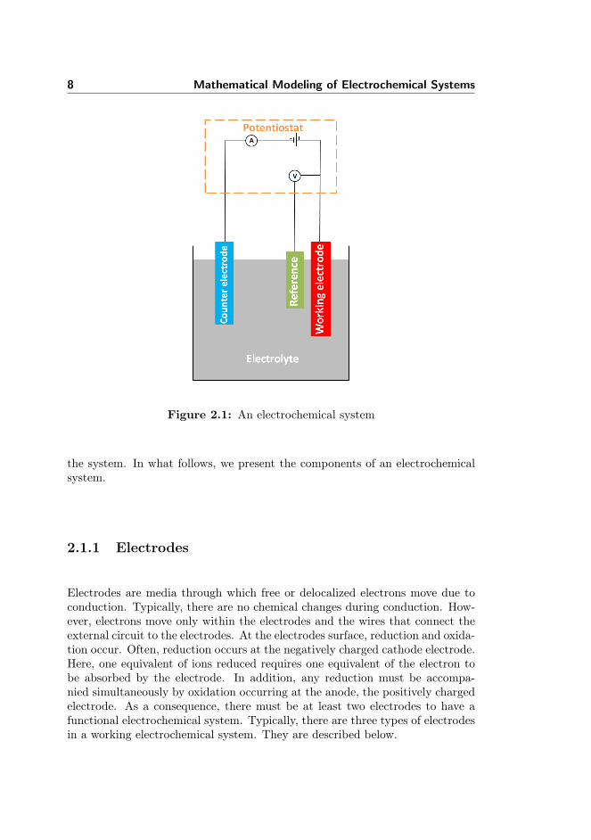
An electrochemical system is a network of interrelated components where chem-ical changes spontaneously induce electric current due to the application of anexternal potential, see Figure 2.1. The system can be complicated by severalfactors. Ions can interact with each other and/or the solvent, they can alsointeract with the boundary of the electrodes and other boundaries present in
8 Mathematical Modeling of Electrochemical Systems
Figure 2.1: An electrochemical system
the system. In what follows, we present the components of an electrochemicalsystem.
2.1.1 Electrodes
Electrodes are media through which free or delocalized electrons move due toconduction. Typically, there are no chemical changes during conduction. How-ever, electrons move only within the electrodes and the wires that connect theexternal circuit to the electrodes. At the electrodes surface, reduction and oxida-tion occur. Often, reduction occurs at the negatively charged cathode electrode.Here, one equivalent of ions reduced requires one equivalent of the electron tobe absorbed by the electrode. In addition, any reduction must be accompa-nied simultaneously by oxidation occurring at the anode, the positively chargedelectrode. As a consequence, there must be at least two electrodes to have afunctional electrochemical system. Typically, there are three types of electrodesin a working electrochemical system. They are described below.

2.1 Electrochemical Systems: concepts and components 9
Working electrode
The working electrode is the electrode of interest in which the electrochemicalreaction is monitored. Its potential is sensitive to the electrolyte’s concentration.A typical working electrode is made from a chemically inert conductor. The mostcommon types include platinum, gold, glassy carbon, graphite and mercury.These electrodes usually have a good positive potential range.
Counter electrode
The counter electrode is an auxiliary electrode which acts as a source or sinkof electrons in an electrochemical system. The presence of a counter electrodein an electrochemical system allows the current to pass through the electrolytesolution so that it does not pass through the reference electrode. This allowsfor removal of varying voltage at the reference electrode due to voltage drop orpolarization at the reference electrode. In an ideal system, the potential of thecounter electrode must remain constant in order to ensure that any change inpotential of an electrochemical system is assigned to the working electrode.
In principle, the nature of the counter electrode should have little or no effect onan electroanalytical measurement. However, if the surface area of the counterelectrode is small relative to the working electrode area inaccuracies may arisedue to the additional resistance imposed by the counter electrode. For thisreason, it is wise to keep the surface area of the counter electrode relativelylarge. Also, the counter electrode should be made of an electrochemically inertmaterial such as platinum or graphite.
Reference electrode
The reference electrode is used to stabilize against voltage drops and polariza-tion effects that would be unavoidable in a two-electrode system. The main pur-pose of the reference electrode is to provide a stable, well-known half-reactionon which to reference the redox process occurring at the working electrode.Reference electrode ensures that any change in an electrochemical system goesthrough the electrolyte thereby affecting the potential of the working electrode.By convention, the reference electrode is the anode.

10 Mathematical Modeling of Electrochemical Systems
2.1.2 Electrolyte
The electrolyte is a medium that supports free moving ions and conducts anelectric current. An electrolyte consists of moving charged particles that con-stitute the electric current. Usually, electrolytes are found in the form of acids,alkalis or salts and most often they contain at least two ions flowing in theopposite directions; positively charged cations and negatively charged anionswhich are attracted to negative and positive electrodes, respectively. One ex-ception to this is the lithium ion which migrates from one electrode to anotherin the lithium battery. Their electrical conduction is usually accompanied bychemical changes. Usually, there is no electron flow in the solution, but throughthe electrode and the external connected wires. Apart from the main electrolytethat partakes in an electrochemical reaction within an electrochemical system, asupporting electrolyte is often added to the system to increase the ionic conduc-tivity of the medium. With the electrolyte one minimizes solution resistance tocharge flow through the electrochemical system. It also minimizes migration asa means of mass transport to the electrode. However, the supporting electrolytedoes not partake in the electrochemical reaction.
2.1.3 External wires
The final component of an electrochemical system is the external wire that con-nects the electrodes to the load so that electrons can flow between the electrodes.The current that flows through the external wire in an electrochemical systemis the measure of the flux of electrons which corresponds to the flux of reactantsor products transformed during the electrochemical reactions.
Having introduced the components of an electrochemical system, we proceed byexplaining the mechanism of the processes that are involved in an electrochem-ical system and develop the mathematical model of a working electrochemicalsystem. We start with the mathematical model of a macro electrochemicalsystem.
2.2 Electrode reaction and kinetics of electrontransfer
When the potential at the electrodes is disturbed, the ions in the electrolytesolution may decompose and results in net chemical changes in the region close

2.2 Electrode reaction and kinetics of electron transfer 11
to the electrode surface. The electrochemical conversion results in a net flux ofionic species at the surface of the electrode and by such a net flux of electronsresults in electrical current flowing through the external circuit. The overallprocess is called the electrode reaction.
An electrode reaction usually involves interchange of charges between electronsfrom the electrode and ionic species in the electrolyte. There are three majorsteps involved in the process: (1)reactants migrate towards and/or outwardthe electrode surface through the mechanism of mass transfer; (2)ionic speciesclose to the surface of the electrode, through charge transfer, absorb or releaseelectron to form product depending on the sign of the potential of the electrode;and finally (3)the products move away from the electrode and fresh reactantsmove towards the electrode surface. The differences between the conductivity ofthe electrode and the electrolyte solution allows for continuous flow of electricityat the electrode/electrolyte interface.
Consider the following electrode reaction,
O + ne−kc−−ka
R, (2.1)
where O and R are the reactants and product respectively, and n is the numberof electrons participating in the reaction, ka, kc are oxidation and reduction rateconstants respectively. By Faraday’s law, the rate of an electrode reaction andthe current density is given as
dN
dt=
j
nF(2.2)
where N is the number of moles of the reactants, j is the current density and Fis the Faraday’s constant. Assuming the constant current density through theelectrode surface, the total current I flowing through the electrode surface canbe obtained by multiplying the surface area A of the electrode with the currentdensity, thus, I = jA.
Furthermore, the net electrical current flowing through the external circuit dur-ing the electrochemical reactions at the electrode/electrolyte interface is givenas I = Ia−Ic where Ia, Ic are the anodic and cathodic currents due to oxidationand reduction, respectively. This implies that the current density satisfies thefollowing relation
12 Mathematical Modeling of Electrochemical Systems
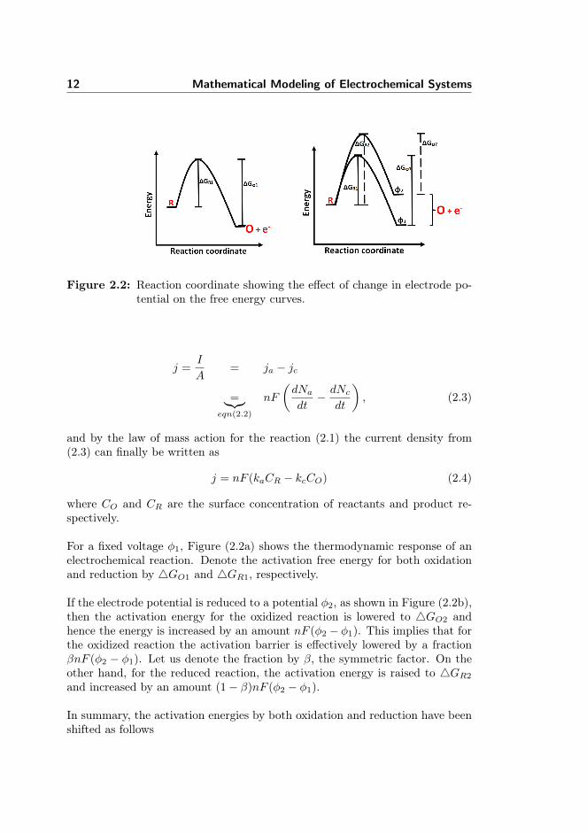
Figure 2.2: Reaction coordinate showing the effect of change in electrode po-tential on the free energy curves.
j =I
A= ja − jc
=︸︷︷︸eqn(2.2)
nF
(dNadt− dNc
dt
), (2.3)
and by the law of mass action for the reaction (2.1) the current density from(2.3) can finally be written as
j = nF (kaCR − kcCO) (2.4)
where CO and CR are the surface concentration of reactants and product re-spectively.
For a fixed voltage φ1, Figure (2.2a) shows the thermodynamic response of anelectrochemical reaction. Denote the activation free energy for both oxidationand reduction by 4GO1 and 4GR1, respectively.
If the electrode potential is reduced to a potential φ2, as shown in Figure (2.2b),then the activation energy for the oxidized reaction is lowered to 4GO2 andhence the energy is increased by an amount nF (φ2 − φ1). This implies that forthe oxidized reaction the activation barrier is effectively lowered by a fractionβnF (φ2 − φ1). Let us denote the fraction by β, the symmetric factor. On theother hand, for the reduced reaction, the activation energy is raised to 4GR2
and increased by an amount (1− β)nF (φ2 − φ1).
In summary, the activation energies by both oxidation and reduction have beenshifted as follows

2.2 Electrode reaction and kinetics of electron transfer 13
4GO2 = 4GO1 + βnF (φ2 − φ1), (2.5)4GR2 = 4GR1 − (1− β)nF (φ2 − φ1). (2.6)
We replace the difference in potential by a reference potential φ and definetransfer coefficients αa = (1 − β)n and αc = βn for the oxidized and reducedreactions respectively, to obtain the following
4GO2 = 4GO1 + αcFφ, (2.7)4GR2 = 4GR1 − αaFφ. (2.8)
As in other chemical reactions, the electrochemical reaction rates are obtainedthrough the Arrhenius equation
ka = k exp
(−4GRRT
), kc = k exp
(−4GORT
), (2.9)
where k is a constant, R and T are the gas constant and the absolute temperaturerespectively. We substitute equations (2.7) and (2.8) into equation (2.9) andobtain
ka = k exp
(−4GR1
RT
)·exp
(αaFφ
RT
), kc = k exp
(−4GO1
RT
)·exp
(−αcFφRT
).
(2.10)Since 4GO1 and 4GR1 are the activation energies at the reference potentialthe following holds
ka = ka exp
(αaFφ
RT
), kc = kc exp
(−αcFφRT
), (2.11)
withka = k exp
(−4GR1
RT
), kc = k exp
(−4GO1
RT
). (2.12)
From equations (2.4), (2.11) we derive the current density observed in an elec-trochemical reaction to be
j = nF
[kaCR exp
(αaFφ
RT
)− kcCO exp
(−αcFφRT
)]. (2.13)
At equilibrium, the rate of the electrochemical reaction is zero. This impliesthat equation (2.13) is set to zero. Let φ0 be the equilibrium potential at which

14 Mathematical Modeling of Electrochemical Systems
this happens so that we have
kaCR exp
(αaFφ0RT
)= kcCO exp
(−αcFφ0RT
), (2.14)
and when we take the logarithm of both sides and re-arrange we obtain theexpression for the equilibrium potential as
φ0 =RT
nF
[ln
(kc
ka
)− ln
(CRCO
)]. (2.15)
Expression given in (2.15) is the Nernst equation, see for example [2, 20, 8].
When there is an electrochemical reaction across the electrode/electrolyte suchthat there is a departure from the equilibrium potential, overpotential η isrecorded. Overpotential is modeled as the difference between the electrode po-tential and the corresponding equilibrium potential,
η = φ− φ0. (2.16)
If we substitute equations (2.15) and (2.16) into equation (2.13) we obtain
j = nF kaCR exp
(αaF
RT
[η +
RT
nFln
(ka
kc
)− RT
nFln
(CRCO
)])
−nF kcCO exp
(−αcFRT
[η +
RT
nFln
(ka
kc
)− RT
nFln
(CRCO
)]).(2.17)
When we perform a few manipulations with equation (2.17) we obtain
j = j0
[exp
(αaF
RTη
)− exp
(−αcFRT
η
)], (2.18)
where j0 is the exchange current density defined by
jo = nF k−βa k1−βc C−βR C1−β
O .
It is the measure of the rate of exchange of the reactant and the product at theelectrode/electrolyte interface at the equilibrium. It also expresses the heightat which both the reactant and the product are at the same activation energylevel. The expression in equation (2.18) is the famous Butler-Volmer equation

2.3 Mass transfer 15
developed by Butler, Volmer and Erdey Gruz [31, 32] in the 1930s. It char-acterizes the rate of electrode reactions as a result of overpotential across theelectrode/electrolyte interface and two kinetic parameters of the reactions. TheButler-Volmer equation suggests that the potential drop from the electrode tothe bulk electrolyte triggers the electrochemical reaction kinetics.
Finally, the Butler-Volmer equation (2.18) is the standard electrochemical ap-proach to model reaction kinetics across the electrode/electrolyte interface.However, it fails to account for the structure of the electrode/electrolyte inter-face which is crucial in order to model a microelectrochemical system. Insteadof considering the potential drop between the electrode and the bulk electrolyte,we postulate that there is a local potential drop across a thin dielectric layercoating, the Stern layer, which is the closest layer to the electrode from theelectrolyte. In addition, we also assume that electron transfer happens at thislayer which means that the potential within the Stern layer also affects the re-action kinetics. In the section on electric double layer, we suggest the boundarycondition such that the Stern layer satisfies a Robin type boundary conditionwhere the normal electric field equates the Stern layer potential. We shall com-bine this boundary condition with the Butler-Volmer equation for the chargetransfer reactions, thereby providing a more realistic boundary conditions for amicroelectrochemical system. An interesting review on the historical review ofsuch an approach can be found in [27].
In what follows, we will introduce another process that affects the reactionkinetics and phenomena on which the whole electrochemical system is based.
2.3 Mass transfer
From the previous section, we have established that the current recorded inan electrochemical system can be influenced by the applied potential and thereaction kinetic constants. On the other hand, before we record any currentelectrode reactions across the electrode/electrolyte interface must occur. Forany net reaction to take place at an appropriate rate, reactants and the prod-ucts must be transported to and from the surface of the electrode in order tobalance the net flux and influence the electrical current recorded across theelectrode/electrolyte interface. In this section, we discuss three mechanisms ofmass transport of reactants in the electrolyte solution towards the electrodesurface and the means, by which the ionic products are transferred back intothe electrolyte solution.

16 Mathematical Modeling of Electrochemical Systems
Convection
Convection stems from a force on the electrolyte solution. In convection, thewhole electrolyte solution travels. The ionic species in the electrolyte solu-tion move towards and leave the electrode surface by being driven in a movingelectrolyte solution. Motivated by the experiment reported in our Paper II,we introduced convection into the electrochemical system through a controlledpump so that only laminar flow profile is considered. The details can be foundin Paper I and Paper II.
In the microfluidic system studied in the papers, the solution is introduced fromthe left hand side and pumped through the pipe with outlet on the right handside. The convective flux of the ionic species Cj traveling at an average velocity,v is given as
Nconv = vCj . (2.19)
Diffusion
Diffusion occurs in all solutions due to concentration gradients. Typically, dif-fusion does not occur due to any physical force, but due to uneven electrolytesolution seeking to maximize its entropy. The Brownian motion of all ionicspecies tries to enhance regions of low concentration from the region of higherconcentration. Diffusion is very significant in an electrochemical system becauseelectrochemical reactions occur at the surface of the electrode. As a consequence,the concentration of the reactants will always be lower at the electrode surfacethan in the bulk electrolyte solution. However, the concentration of the prod-ucts near the electrode will be higher compared to the ones further into theelectrolyte solution.
The diffusive flux is proportional to the concentration gradient with the diffusioncoefficient as its proportionality. Since a positive concentration gradient willinduce a flux towards a negative direction, we model the diffusive flux for ionicspecies Cj as follows
Ndiff = −Dj∇Cj , (2.20)
where Dj is the diffusivity of ionic species j. This is called the first Fick’s law.
2.3 Mass transfer 17
Migration
Mass transfer due to migration is a consequence of the electrostatic effect whichresults from the application of potential difference between the electrodes andthe presence of charged ionic substances in the electrolyte solution. The appli-cation of potential difference between the electrode surfaces creates a chargedsurface, thereby attracting or repelling any charged species near the electrodedue to the presence of the electrostatic forces. Let φ be the local potential inany region of the electrolyte bulk solution. Then, the flux due to migration canbe written as
Nmig = −zjujFCj∇φ, (2.21)
where zj , uj are the charge and the mobility of the ionic species j.
In what follows, we formally establish the mathematical model which describesa working electrochemical system.
Total ionic flux in the bulk electrolyte
In an electrolyte solution the total flux is given as the contribution of fluxes dueto diffusion, migration and convection which is
Nj = − Dj∇Cj︸ ︷︷ ︸diffusion
−ujzjFCj∇φ︸ ︷︷ ︸migration
+ Cjv︸︷︷︸convection
. (2.22)
If we use the Nernst-Einstein equation, we can re-write expression (2.22) asfollows
Nj = −Dj
(∇Cj +
zjF
RTCj∇φ
)+ Cjv, (2.23)
which equivalently can be re-written as
Nj = −Dj
RTCj∇ (RT ln(Cj) + zjFφ) + Cjv. (2.24)
From thermodynamics, the electrochemical potential of ionic species j of uniformconcentration Cj and potential φ in an electrolyte solution can be defined by
µj = µoj +RT ln(γjCj) + zjFφ, (2.25)

18 Mathematical Modeling of Electrochemical Systems
where µoj and γj are the standard electrochemical potential and the activitycoefficient, respectively. We can therefore re-formulate the total ionic flux withinthe electrolyte solution as follows
Nj = −Dj
RTCj∇µj + Cjv. (2.26)
This implies that the gradient of the electrochemical potential seems to be thedriving force for migration and diffusion, although the flux is still complicated bythe presence of the convection in the system. As will be seen later, the activitycoefficient γj shall be modeled to account for the finite size of ionic species inthe bulk electrolyte.
2.3.1 Mass and charge conservation
In this section, we start by considering the charge conservation where we definethe total current in an electrolyte solution and then state the mass conservationfor the concentration of the ionic species.
In an electrolyte solution, the movement of ionic species contributes to the totalnet current. If we assign the charge Fzj to the flux of the ionic species and sumthem over all species, then the total net current in the electrolyte solution isgiven by
i = F∑
j
zjNj . (2.27)
We substitute the flux expression (2.24) into equation (2.27) and expand theresulting expression to obtain
i = −F 2(∑
j
z2jujCj)∇φ− F∑
j
zjDj∇Cj + F (∑
j
zjCj)v. (2.28)
Equation (2.28) suggests that the net current in the electrolyte solution due toionic species is determined by both the concentration and the potential gradi-ent as well as the velocity of the electrolyte solution. Since in an electrolytebulk solution the concentration of the charged ionic species must be electrically
2.3 Mass transfer 19
neutral, then the electroneutrality condition is defined as∑
j
zjCj = 0. (2.29)
The last term in the electrical current equation (2.28) is the electroneutralitycondition and hence the equation for the current becomes
i = −κ∇φ− F∑
j
zjDj∇Cj , (2.30)
where κ is the electrolyte conductivity defined by
κ = −F 2∑
j
z2jujCj . (2.31)
Now recall the ionic flux equation (2.24). For each ionic species j the equationdescribing the mass balance is given by
∂Cj∂t
= −∇ · (−ujzjFCj∇φ−Dj∇Cj + Cjv) + Sj . (2.32)
Equations (2.32) are commonly referred to as the Nernst-Planck equations.Here, Sj is the source or sink term which could be used to describe any bulkreaction to produce or consume ions in the electrolyte solution. Throughoutthis work, we set Sj = 0 since no species are allowed to be created in the bulkelectrolyte.
When we multiply the Nernst-Planck equations (2.32) by Fzj and sum over jwe obtain
∂
∂t
∑
j
(FzjCj) = −∇ ·∑
j
Fzj(−zjujFCj∇φ−Dj∇Cj + Cjv), (2.33)
and by electroneutrality condition (2.29) the left hand side equals zero. Theconvective term on the right hand side also vanishes due to the electroneutralitycondition. And when we substitute the expression for current (2.28) into themass balance equation equation (2.33), we obtain the following equation for theconservation of charges:
∇ · i = 0, (2.34)
Equations (2.32) and (2.34) couple the ionic concentration and the electric po-tential in the bulk electrolyte. However, in order to close the system we need to

20 Mathematical Modeling of Electrochemical Systems
determine the velocity field v due to the convective term. This can be done bysolving the Navier-Stokes equations for an incompressible flow,
∇ · v = 0 , (2.35)
ρ
(∂v
∂t+ v · ∇v
)= −∇p+ µD∇2v + sf . (2.36)
The fluid density is denoted by ρ, p is the pressure, µD is the dynamic viscos-ity and finally sf denotes an external force per unit volume [33, 34]. Finally,equations (2.32), (2.34), (2.35) and (2.36) must be solved with the appropriateboundary conditions.
2.3.2 Boundary conditions
As we have established in the electrode kinetics section, the measured currentin an electrochemical system depends both on the potential at the surface ofthe electrode - at least within the thin layer above it and the electrochemicalreactions. It is necessary to prescribe the right boundary conditions to properlycomplete the model. At the inlet, we specify constant concentrations of the ionicspecies and a no flux boundary condition −n ·Nj = 0 on the fluidic cell walls,where n is the unit normal pointing towards the electrolyte. At the outlet of the
cell we specify D∂Cj∂n
= 0. At the insulating surfaces ∂Ωins there is no currentflow, which means that the normal current density in across such a boundary iszero, that is
in = 0 on ∂Ωins. (2.37)
In other words, from the conservation of the electric current (2.34) we canprescribe Neumann type boundary conditions
κ∂φ
∂n= −
∑
j
zjDj∂Cj∂n
on ∂Ωins . (2.38)
However, at the electrode surface the ionic flux for each species j can be modeled

2.4 Electroanalytical techniques 21
by the normal current density determined from electrode kinetics,viz
κ∂φ
∂n+∑
j
zjDj∂Cj∂n
= in(Cj , φ, v;φapp) on ∂Ω . (2.39)
Here φapp is the applied potential on the electrode surface. The electrode kineticsis given by the Bulter-Volmer Equation established in equation (2.18).
Finally, the boundary conditions for the Navier-Stokes equations (2.35) and(2.36) can be prescribed depending on the geometry of the computational do-main. Normally, one prescribes no-slip and no penetration conditions for thevelocity field at the both the insulated boundary and at the surface of theelectrode. An inlet and outlet flow conditions must also be prescribed for thepressure variable. We considered specific cases in Paper I and Paper II.
2.4 Electroanalytical techniques
Electroanalytical methods are techniques that can be used to detect and char-acterize chemical and physical properties of materials in an electrochemicallycharged fluidic environment. These techniques can be used to illustrate masstransport (diffusion, convection, migration), thermodynamics, reaction kinetics,surface chemistry of an electrochemical system. In this thesis, we consider thecyclic voltammetry (CV) technique. The full model for the cyclic voltammetrycan be found in Paper I and Paper II.
In a CV measurement, a series of electric potentials is applied at the workingelectrode. These potentials vary piecewise linearly and periodically with timeas seen in Figure 2.3. The electrical current response is then recorded andplotted against the applied potentials. The applied potentials control the surfaceconcentration of the redox couple that participate in an electrochemical reaction.

22 Mathematical Modeling of Electrochemical Systems
Figure 2.3: Plot of forward and backward scan for applied potential over aperiod of time.
The slope of the line in Figure 2.3 is the scan rate of the cyclic voltamme-try. It measures how fast the applied potential is swept forward and backwardduring the voltammetry measurement. The scan rate in Figure 2.3 is 50mV/sand corresponds to the experimental duration of about a quarter of an hour.In Figure 2.4, we record the current response and the corresponding evolvingconcentration profile of the reactants and the products at the surface of theelectrode.
Figure 2.4: Plot of a) current recorded over time, b) evolution of concentrationof ionic species over time, blue (reactants), green (products).
When the potential scan is initiated for the first sweep, current increases andthe start out concentration (the blue colour line in Figure 2.4b) of the reactantsis driven towards zero. At the period when the concentration at the electrodesurface is zero, the gradient of the concentration relaxes due to mass transportsuch that the corresponding current also relaxes. Finally, the concentration of

2.5 Finite size ion and electric double layer (EDL) 23
the reactants return to its initial value at the surface of the electrode whenthe potential scan is reversed for the second sweep. The same is true for thecorresponding current recorded.
2.5 Finite size ion and electric double layer (EDL)
The central feature in this thesis is the modeling of microelectrochemical sys-tems. Up until now, the models we have presented are suited for describingmacroelectrochemical systems and the one in which the electrolyte solution canbe considered dilute. Although the models have been used as an approxima-tion to a microelectrochemical system in several studies, they are not entirelyaccurate. One of the drawbacks of the model is that the model treats the ionicspecies as point charges despite the fact that ions naturally have finite sizes;the diameter of an ion with its hydration shell is usually 3-6Å. Therefore, thedetailed molecular structure of the ion is significant in the model formulationfor the micro-size systems.
When the potential is applied to the electrodes they get polarized and chargesmove to their surfaces. Since the electrolyte solution also contains chargedions electric field is generated close to the surface of the electrode and hence,attracts counter ions. However, if ions are treated as point charges, then theionic concentration gets very large which leads to crowding of ions in the regionof the electric double layer. In order to overcome this problem, we introducethe finite size effect of the ionic species into the model.
Recall, the electrochemical potential of ionic species j
µj = µoj +RT ln(γjCj) + zjFφ (2.40)
from the ionic flux equation (2.26).
The activity coefficient γj can be directly related to the ion diameter a and canbe used to account for the finite size of the ionic species. Let the maximumconcentration of the ions be given by cmax = a−3 [35], then by [36]
γj =1
1−∑j a3Cj
. (2.41)

24 Mathematical Modeling of Electrochemical Systems
Figure 2.5: schematic of double layer
When we insert equation (2.41) into equation (2.26) we obtain
Nj = −Dj
∇Cj +
zjF
RTCj∇φ+
a3Cj1−∑j Cja
3(∑
j
∇Cj)
+ Cjv. (2.42)
Notice that the third term in equation (2.42) is a singular diffusion term thatleads to the saturation of the ionic species close to the electrode surface. Itrepresents the finite size of the ionic species in the formulation.
In the model development for the conservation of mass, we have assumed elec-troneutrality which is a zero constraint on the sum of ionic concentration presentin an electrolyte. However, this is only true in the bulk electrolyte solution.There is a layer where there is an imbalance of charges and where the elec-troneutrality conditions breaks down, this layer is the electric double layer. Thestructure of double layer combines the Stern layer and the diffuse layer, seeFigure (2.5).
The Stern layer is considered the charge free layer that is sandwiched betweenthe electrode and the layer immediately before the diffuse layer. It is a region,which accounts for the intrinsic capacitance of the compact part of the electrode-electrolyte interface. The compact-layer charge may contain solvated ions at thepoints that are closest to the electrode. The capacitance also accounts for thedielectric polarization of the solvation layer. Hence, Stern layer thickness is anadjustable parameter that can be used to study the composition of the doublelayer.
The diffuse layer is the region containing the non-zero space charge density.Consequently, there are large electrical field strengths. In this layer, the gra-

2.5 Finite size ion and electric double layer (EDL) 25
dient of the ionic species concentration counters the electric field forces actingon the ionic species. Therefore, the gradients of the ionic concentration andthe electrical potentials in the diffuse layer are very large compared to steadychanges in the electroneutral bulk electrolyte. The combination of the com-position of Stern and the diffuse layers makes the double layer to have greatinfluence on the rate of charge transfer at the electrodes.
The classical Butler-Volmer equation reported in equation (2.18) indicates thatelectrochemical reactions are triggered by the over-potential, that is, the dropin potential between the electrode and the bulk electrolyte solution. However,when including the double layer into the picture of the electrochemical reaction,the proper boundary condition for the potential drop should come from thepotential drop across the Stern layer as this is where the reactions actuallytakes place. The potential drop across the Stern layer results from the strengthof the electrical field at the reaction plane according to the following,
4φs = λS∇φ · n (2.43)
where λS is the effective width of the Stern layer of the electric double layer,and n is the normal pointing towards the electrolyte solution. The left handside of equation (2.43) is the difference between the applied potential φappl and
the electric potential φ∣∣∣∣rp
at the reaction plane shown in Figure 2.5.
We replace the overpotential in the Butler-Volmer equation in (2.18) by thepotential drop across the Stern layer and we finally obtain
j =
[kaCO exp
(αaF
RT4φs
)− kcCR exp
(−αcFRT
4φs)]
. (2.44)
In conclusion, for a microelectrochemical system we substitute the fluxes in theequation of mass balance (2.32) by (2.42). In addition, we solve for the localpotential appearing in the mass balance equations via the Poisson’s equationwith its source as the charge density, that is
−∇ · (εb∇φ) = F∑
j
zjCj , (2.45)
where εb is the dielectric permitivity. Notice that the right hand side is notzero for a microelectrochemical system. The boundary conditions to solve thesystem of equations are given by (2.43) and (2.44), respectively.
In the next section, we present the main results based on the implementationof the finite element method of the derived models.

26 Mathematical Modeling of Electrochemical Systems

Chapter 3
Summary of main results
This section is divided into two parts. The first part describes the results andcontribution of Papers I and II. We present the solution to equations (2.32),(2.34), (2.35), (2.36) coupled with the boundary conditions defined in chapter 2.The experimental set-up for the model is described in Paper II. The second parthighlights the contribution of Paper III where we present the results of the modelfor microelectrochemical systems. The model accounts for the structure of theelectrode/electrolyte interface and also incorporates finite size properties of theionic species. We conclude this section by summarizing the major contributionsof this thesis.
Part I
In Paper II, we introduce the experimental set-up of an electrochemical systemin which the electrolyte solution is transported by all the mechanisms of masstransfer. Full details of the experiment can be found therein. Here, we areinterested in setting up the numerical solution using the Finite Element method(FEM) program COMSOL [37]. We do not give details of the theory of FEM.However, there are unlimited resources where the theory and numerics of FEMhave been reported, for more details readers are referred to [38, 39, 40, 41],among others.

28 Summary of main results
Figure 3.1 shows the fluidic cell which approximates the experimental setup.Only the working electrode is shown. As reported in Paper II, the fluidic cellcan be approximated by a 2-dimensional computational domain because of thelaminar nature of the flow. The full details can be found in Paper II.
computational domain
l
C jWe
flowW
L
H
y
x
z
Figure 3.1: schematic of the fluidic cell.
We validate the results of simulation of the model and assess the accuracy of thesolution method by systematic mesh refinement until there are no changes in theestimated response current curves. A typical mesh refinement for computationis shown in Figure 3.3.
l
L
Ω∂ ins
Ω∂ ins
t
inflow outflowH l
L
t
Ω∂ ins
Ω∂ ins
inflow outflowH
Figure 3.2: Plot of a) computational domain of an electrode placed at thebottom of the fluidic cell, b) computational domain of an electrodeplace in the middle of the fluidic cell.
Figure 3.3: Plot of a zoomed-in mesh grid showing dense elements around amid placed electrode.

29
The high density of the mesh is due to local systematic mesh refinement aroundthe electrode where there are large solution gradients. In order to ensure com-promise between computational time and the accuracy of the results we haveused about 35000 elements in our computations. For the time integration, wehave employed the implicit Euler method that is stable for the numerical com-putations.
We used a two step approach for solving the coupled fluid and ion-transportproblems. First, we solve for the steady state solution to the incompressibleNavier-Stokes equations and then substituted the steady state solution of thevelocity field into the ion transport problem. The fluid flow problem was solvedby discretizing the computational domain using the linear Lagrange finite el-ements for the pressure field and quadratic elements for the velocity field. Inaddition, we employed quadratic elements for the ion transport problem whilethe linear Lagrange element was chosen for the potential field.
Figure 3.4: Plot of a) contour field with electrode on the floor, b) contour fieldwith electrode in the middle.
Figure 3.5: Flow profile across z-axis of the channel.

30 Summary of main results
Figure 3.4a and Figure 3.4b are the contour plots of the pressure across the z-axisof the fluidic cell for both the electrodes placed at the bottom and the middleof the the fluidic cell, respectively. Figure 3.5 also shows the velocity profileacross the z-axis. It is clear from the figures that fresh reactants are always inconstant supply at the working electrode placed in the middle of the cell. Thisis because the maximum velocity is at the tip of the parabolic profile of thevelocity. Therefore, at a high scan rate, there is either the high concentrationof the products or the reactants that are close to the surface of the electrode.Consequently, we expect higher currents to be recorded in the system with theelectrode in the middle. More detailed analysis is considered both in Paper Iand Paper II.
In what follows, we present a series of cyclic voltammetries for various scenariosfrom the simulated electrochemical system from the previous section. We havechosen laminar volumetric flow rates ranging from 0 - 250µL/min. Figures3.6a,b show cyclic voltammetry curves for systems with both electrodes in themiddle as well as on the bottom of the fluidic system. They depict the effect offlow rates on the CV.
Figure 3.6: Plot of a) cyclic voltammetry recorded at the electrode placed inthe middle of the fluidic cell, b) cyclic voltammetry recorded atthe electrode placed at the bottom of the fluidic cell.
Taking a closer look at Figure 3.6a, at flow rates of about 50 - 150µL/minpeak currents are observed. The reason is that during the forward scan thereis an accelerated electrode/electrolyte reaction and fast enough to allow chargeexchange and results in an increase in current recorded. However, due to thereaction at the surface of the electrode, the concentration of the reactants isdepleted and the current soon is controlled by the diffusion of the reactantstowards the electrode. On the other hand, as the flow rate increases to about250µL/min, the CV curve becomes thinner and the peak current disappears assaturation is quickly reached. This is due to the rapid inflow of the reactants andquick removal of the products induced by the convection. There is a reduction

31
in diffusion layer thickness for electro active species and hence mass transportis controlled by the convection.
Figure 3.7: Plot of a) cyclic voltammetry showing very high flow rate recordedat the electrode placed in the middle of the fluidic cell, b) cyclicvoltammetry recorded at the electrode placed in the middle of thefluidic cell showing the effect of scan rate.
For the case of Figure 3.6b, peak currents are always recorded for any choiceof moderate flow rates. This could be explained by our earlier argument thatfor a bottom placed electrode, the rate of furnishing the electrode surface withfresh reactants is slow. Hence, the reactants close to the surface of the electrodewill always undergo reduction or oxidation, thereby recording peak current atall time. However, in an extreme case of high volumetric flow rate (usuallybeyond the laminar flow regime) as in Figure 3.7a the hysteresis in the CV curvecompletely disappear. The system is completely dominated by convection. Wealso present CV curves and the effect of the scan rates in Figure 3.7b. Thereis clearly a corresponding increase in scan rate and the currents recorded withhighest scan rate showing the highest peak current. The faster the scan rate,the faster the diffusion layer is established over a shorter distance.
In conclusion, we have shown the simulation of cyclic voltammetry using theflexible and the powerful finite element solver COMSOL. This allows to solveproblems with complex geometry and provides the framework that leads tocomplex design of an electrochemical system. However, the main result here isthat we can now assess the influence of the convection and the scan rate to thedynamics of the electrochemical system. The result also shows that placementof the electrodes is very essential.

32 Summary of main results
Part II
In this section, we solve the model for an electrochemical system that incor-porates the finite size properties of the ionic species and account for the elec-trode/electrolyte structure of the interface. The aim of this section is to sum-marize the topic covered in Paper III. The extensive mathematical derivationscan be found in Paper III and the extended non-dimensionalization of the modelequations are found in Appendix A. Here, we explain interesting numerical re-sults and highlight an analytical result that provide insight into the dynamicsof the electric double layer to the bulk layer. We strongly emphasize here thata system of one dimension is considered because higher dimensions still posechallenges. This study serves as a motivation to overcome limitations found inhigher dimensions.
We start by lifting some of the formulations from Paper III. Consider the di-mensionless mass transport and Poisson’s equations involving an anion C1 anda cation C2 and the local potential in a microelectrochemical system,
∂C1
∂t= k1
∂
∂x
(∂C1
∂x− z1C1
∂φ
∂x+
νC1
1− ν(C1 + C2)
∂(C1 + C2)
∂x
), (3.1)
∂C2
∂t= k2
∂
∂x
(∂C2
∂x+ z2C2
∂φ
∂x+
νC2
1− ν(C1 + C2)
∂(C1 + C2)
∂x
), (3.2)
−ε2 ∂2φ
∂x2= z2C2 − z1C1, (3.3)
with the following boundary conditions
k1
(∂C1
∂x− z1C1
∂φ
∂x+
νC1
1− ν(C1 + C2)
∂(C1 + C2)
∂x
)= jF , (3.4)
k2
(∂C2
∂x+ z2C2
∂φ
∂x+
νC2
1− ν(C1 + C2)
∂(C1 + C2)
∂x
)= jF , (3.5)
φ
∣∣∣∣rp
= φ|e ∓ δε∂φ
∂x
∣∣∣∣rp
. (3.6)
Here, jF = kRC1,S exp(−αz14φs) − kOC2,S exp((1 − α)z24φs). We commenthere that equations (3.1 - 3.6) are derivations from the equations presented in

33
section 2.5. See the derivation in Paper III. All the parameters are also definedtherein.
We numerically solve the model with two case scenarios. The case with a blockedelectrode where there is no charge transfer jF = 0 and the case with jF 6= 0where only the cation reacts at the electrode. The domain of computation is0 ≤ x ≤ 1 and dimensionless potentials of 0 and 10 are applied at the leftand right boundary respectively. Throughout the computation, we have chosenδ = 0.1 which means the diffuse layer is ten times the Stern layer.
Model validation
We validate our numerical computations by considering an interesting case pro-posed by [23]. They solved a steady state problem where one of the ionic speciesreacts and is absorbed by the electrode. The model does not contain the finitesize properties but incorporated Stern’s boundary conditions. We set up thesame problem with the finite size constraint and solve the equivalent transientproblem.
Figure 3.8: Plot of a) evolution of concentration , b) evolution of charge den-sity.
It is interesting to see that the results approach the steady state solutions for theconcentration, potential and the charge density, see Figures 3.8-3.9 as reportedin [23], page 1471. In what follows we now present the summary of the resultsbelow.
34 Summary of main results
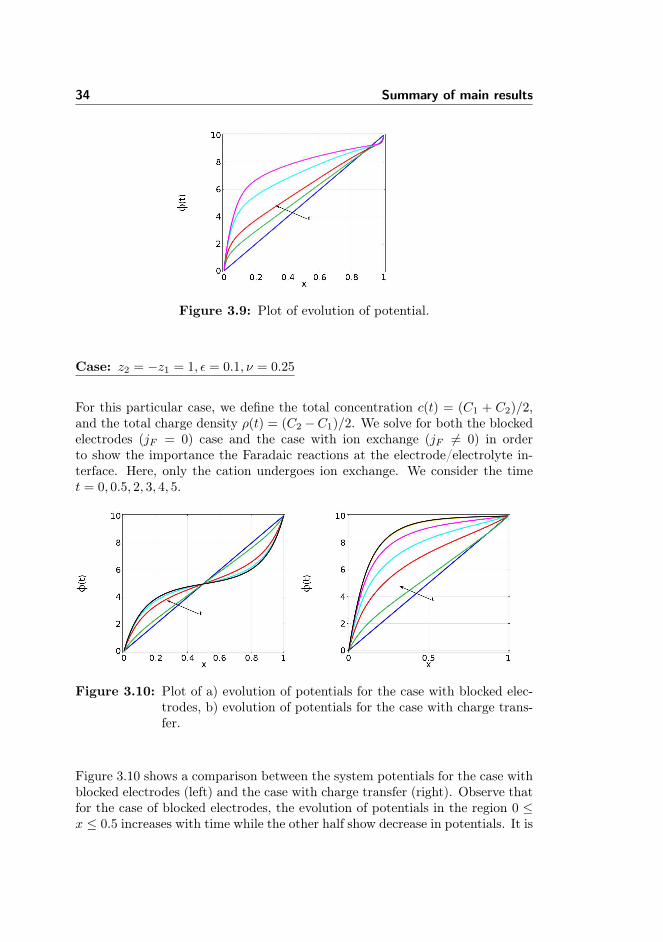
Figure 3.9: Plot of evolution of potential.
Case: z2 = −z1 = 1, ε = 0.1, ν = 0.25
For this particular case, we define the total concentration c(t) = (C1 + C2)/2,and the total charge density ρ(t) = (C2 −C1)/2. We solve for both the blockedelectrodes (jF = 0) case and the case with ion exchange (jF 6= 0) in orderto show the importance the Faradaic reactions at the electrode/electrolyte in-terface. Here, only the cation undergoes ion exchange. We consider the timet = 0, 0.5, 2, 3, 4, 5.
Figure 3.10: Plot of a) evolution of potentials for the case with blocked elec-trodes, b) evolution of potentials for the case with charge trans-fer.
Figure 3.10 shows a comparison between the system potentials for the case withblocked electrodes (left) and the case with charge transfer (right). Observe thatfor the case of blocked electrodes, the evolution of potentials in the region 0 ≤x ≤ 0.5 increases with time while the other half show decrease in potentials. It is

35
interesting to see that the increase and the decrease are of the same proportion.The slope taken at both ends in the vicinity very close to the electrode are equal,that is, equal magnitude of electric field in the electric double layer.
Figure 3.11: Plot of a) evolution of concentration for the case with blockedelectrodes, b) evolution of concentration for the case with chargetransfer.
For a microelectrochemical system the close proximity of the electrodes meansmigration plays a prominent role in the ion transport. But the steep slope of thepotential field around the double layer means the huge electric field will repeland/or attract each ionic species depending on its charge. This is observed inFigure 3.11a which shows the evolution of ionic concentration in time for thecase of blocked electrodes. The boundary layer formed by quick accumulationof charges is evident. Notice the symmetry in Figure 3.11a. Equal amount ofthe species move in the opposite direction towards the boundary where it iscrowded. Another observation is that the concentration in the bulk approacheszero ionic concentration.
Figure 3.12: Plot of a) evolution of charge density for the case with blockedelectrodes, b) evolution of charge density for the case with chargetransfer.

36 Summary of main results
On the other hand, in the case with the ion exchange in Figure 3.10b, we observea very steep gradient, electric field, of the potential close to the left electrodethan the right electrode. This is the consequence of large amount of reactingions, in this case the cation, accumulating faster in the boundary layer. Notethat the total amount of the anion must be fixed and under the influence ofthe electric field its distribution becomes unbalanced and since electroneutralitymust hold in the bulk electrolyte, equal amount of the anion and cation concen-tration must be present. This is clearly observed in the charge density displayedin Figure 3.12. An interesting observation is that in the bulk electrolyte thecharge density is close to zero. This means that equal amount of ionic speciesis present in the bulk region. Hence, the approximation of the electroneutralityholds in the bulk electrolyte. However, notice the boundary layers in this caseextends towards the bulk electrolyte. Finally, at time t = 5, we observe thatboth the anion and the cation concentration are zero close to the right electrodein Figure 3.12b.
Case: z1 = −1, z2 = 2, ε = 0.01, ν = 0.25
The results for the case with different valencies are presented in this section. Weshow the time evolution of the anion and the cation separately in Figure 3.13.The results are plotted for time t = 0.001, 0.01, 2.5, 5. We observe that at earliertime t = 0.001, both the anion and the cation are driven towards zero valuesclose to the electrodes on the left and the right, respectively. Furthermore, theymigrate towards the electrodes on the right and the left, respectively.
Figure 3.13: Evolution of concentrations of a) anion and b) cation, for thecase z1 = −1, z2 = 2, ε = 0.01.
After some time, the anion tends towards zero in the vicinity of both electrodes.This is because it diffuses towards the bulk electrolyte in order to satisfy the

37
electroneutrality condition. However, an interesting observation for the cationshows that the excess concentration accumulate on the right which is a completedeviation from the case treated in the previous section. Notice the charge densityshown in Figure 3.14 where electroneutrality holds in the bulk region except inthe double layer.
Figure 3.14: Evolution of charge density for the case z1 = −1, z2 = 2, ε =0.01.
Parameters ν, ε
Figure 3.15 shows the effects of the finite ion size properties and the parameterthat characterizes the double layer. We have used the previous example for bothcases.
Figure 3.15: Plot of cation field for the cases a) ν = 0, b) ν = 0.1, 0.2, 0.25.
The absence of the steric effect shows that ion concentration goes to infinitywhile when it is present, the ion concentration is bounded by the inverse of the
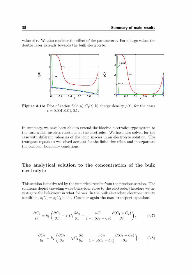
38 Summary of main results
value of ν. We also consider the effect of the parameter ε. For a large value, thedouble layer extends towards the bulk electrolyte.
Figure 3.16: Plot of cation field a) C2(t) b) charge density ρ(t), for the casesε = 0.001, 0.01, 0.1.
In summary, we have been able to extend the blocked electrodes type system tothe case which involves reactions at the electrodes. We have also solved for thecase with different valencies of the ionic species in an electrolyte solution. Thetransport equations we solved account for the finite size effect and incorporatesthe compact boundary conditions.
The analytical solution to the concentration of the bulkelectrolyte
This section is motivated by the numerical results from the previous section. Thesolutions depict traveling wave behaviour close to the electrode, therefore we in-vestigate the behaviour in what follows. In the bulk electrolyte electroneutralitycondition, z1C1 = z2C2 holds. Consider again the mass transport equations
∂C1
∂t= k1
(∂C1
∂x− z1C1
∂φ0∂x
+νC1
1− ν(C1 + C2)
∂(C1 + C2)
∂x
), (3.7)
∂C2
∂t= k2
(∂C2
∂x+ z2C2
∂φ
∂x+
νC2
1− ν(C1 + C2)
∂(C1 + C2)
∂x
). (3.8)

39
We then multiply equations (3.7) and (3.8) by k2 and k1 respectively, and aftera few re-arrangements we invoke the electroneutrality condition and obtain
∂C1
∂t=
∂
∂x
(D[ν,C1]
∂C1
∂x
), (3.9)
which is a non-linear diffusion equation for C1 with effective diffusivity
D[ν,C1] =k1k2
(z1+z2
z1k1+z2k2
)
1− ν(z1+z2z2
)C1,
(3.10)
that depends on both the variable C1 and the steric effect parameter ν.
To solve equation (3.9), we introduce the following constants
L1 = k1k2
(z1 + z2
z1k1 + z2k2
)and L2 = ν
(z1 + z2
z2
),
therefore equation (3.9) becomes
∂C1
∂t= −L1
L2
∂
∂x
(∂
∂x[ln(1− L2C1)]
). (3.11)
Now, we propose a function
σ(t, x) = − ln(1− L2C1), (3.12)
and with a few manipulations, equation (3.9) becomes
e−σ∂σ
∂t= L1
∂
∂x
(∂σ
∂x
). (3.13)
We therefore, seek a travelling wave solution σ(x, t) ≡ c(ξ) with ξ = x− vt thatsatisfies the following ODE
v∂e−c
∂ξ= L1
∂
∂ξ
(∂c
∂ξ
). (3.14)
Integrating equation (3.14) gives
L1∂c
∂ξ= ve−c + L3, (3.15)
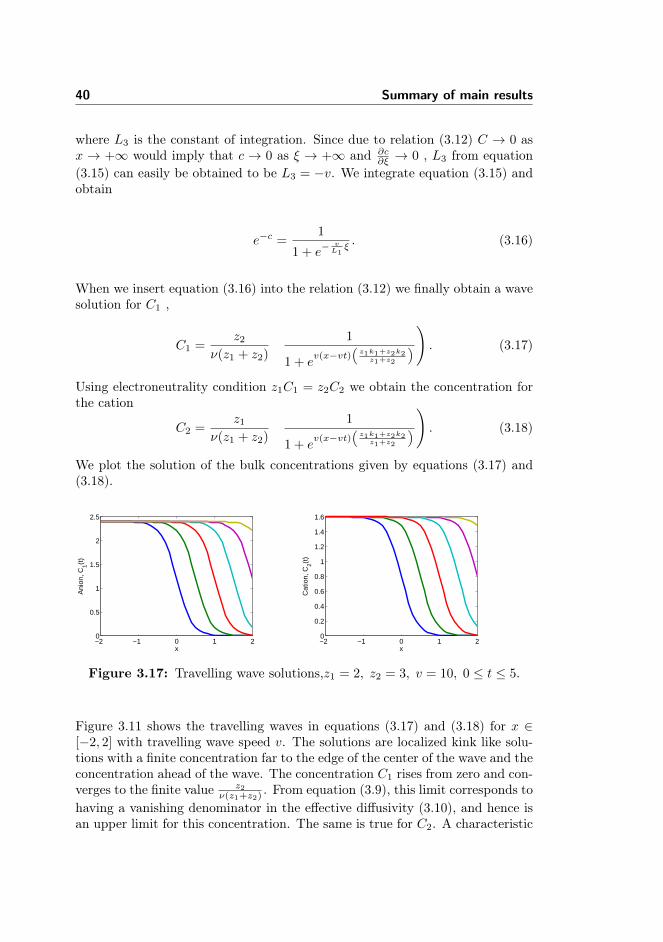
40 Summary of main results
where L3 is the constant of integration. Since due to relation (3.12) C → 0 asx → +∞ would imply that c → 0 as ξ → +∞ and ∂c
∂ξ → 0 , L3 from equation(3.15) can easily be obtained to be L3 = −v. We integrate equation (3.15) andobtain
e−c =1
1 + e−vL1ξ. (3.16)
When we insert equation (3.16) into the relation (3.12) we finally obtain a wavesolution for C1 ,
C1 =z2
ν(z1 + z2)
(1
1 + ev(x−vt)
(z1k1+z2k2
z1+z2
)). (3.17)
Using electroneutrality condition z1C1 = z2C2 we obtain the concentration forthe cation
C2 =z1
ν(z1 + z2)
(1
1 + ev(x−vt)
(z1k1+z2k2
z1+z2
)). (3.18)
We plot the solution of the bulk concentrations given by equations (3.17) and(3.18).
−2 −1 0 1 20
0.5
1
1.5
2
2.5
x
Ani
on, C
1(t)
−2 −1 0 1 20
0.2
0.4
0.6
0.8
1
1.2
1.4
1.6
x
Cat
ion,
C2(t
)
Figure 3.17: Travelling wave solutions,z1 = 2, z2 = 3, v = 10, 0 ≤ t ≤ 5.
Figure 3.11 shows the travelling waves in equations (3.17) and (3.18) for x ∈[−2, 2] with travelling wave speed v. The solutions are localized kink like solu-tions with a finite concentration far to the edge of the center of the wave and theconcentration ahead of the wave. The concentration C1 rises from zero and con-verges to the finite value z2
ν(z1+z2). From equation (3.9), this limit corresponds to
having a vanishing denominator in the effective diffusivity (3.10), and hence isan upper limit for this concentration. The same is true for C2. A characteristic

3.1 Contributions of the thesis 41
feature of the travelling wave solution is the uniform electroneutrality. For anelectrolyte in a tube, the travelling wave solution corresponds to an inflow fromthe left of ions at a concentration equal to the upper limit arising from the stericeffect and that this ion density is pushed into the tube. We imagine that thetube initially is filled with solvent through which the ions are transported.
3.1 Contributions of the thesis
The study of microelectrochemical systems is still an emerging field with lots ofpotentials to be explored as well as grounds to be covered. Here, we list some ofthe contributions of the present study, which we hope will improve and impactthe application of microelectrochemical systems.
The first part of the thesis deals with mathematical modelling and numericalapproximation of a microelectrochemical system using the well known Nernst-Planck equation coupled with the Poisson equation. The motivation for the firstpart of the thesis comes from the need to improve the experimental design ofthe microelectrochemical system. We validate the numerical model of a cyclicvoltammetry experiment for a flowing electrolyte solution in a microfluidic chan-nel against a corresponding physical experiment. We find that the placementof the electrodes in a channel plays a very important role in this model. Thisis one of the distinctions of this study compared to numerous studies that havebeen reported in the articles, for example, [42, 43, 44, 45, 46, 47, 48]. We havealso shown the effects of the moderate and extreme flow rates on the cyclicvoltammetry experiment.
The electrochemical reactions considered in the first part of the thesis are be-lieved to be triggered by the potential drop between the electrode and the bulkelectrolyte solution. There is also an approximation of the electroneutrality con-dition, which means that the right hand side of the electric potential equationis zero. However, for microelectrochemical systems the electrode/electrolyte in-terface plays a crucial role in the electrochemical reactions. Furthermore, theelectroneutrality does not hold near the electrode/electrolyte interface. The sec-ond part of the study attempts to solve a general microelectrochemical model byincorporating these conditions into the model equations. In the second part ofthe thesis, we provide a general framework which allows for electrolytes of anyvalence as opposed to a binary electrolyte solution that have been considered inprevious studies, [23, 29, 30, 49, 50].
As noted by Olsen et al [30], for most electrochemical reactions, it is not enoughto assume binary electrolyte solutions. This has been a daunting task even for

42 Summary of main results
the steady state case [51]. Here, we numerically solved the problem in theframework of general/arbitrary electrolytes even for the transient case. Wehave also extended previous studies to the case with Faradaic reactions at theelectrode/electrolyte interface. We observe that charge transfer complicates thedynamics of the electric double layer. The presence of non-zero right hand sideand a small conductivity occurring at the left hand side of the Poisson equationensure the build up of boundary layers near the electrode/electrolyte interface.We were able to establish this from the numerical results. Finally, we establishthat the ionic concentrations in the bulk electrolyte move with the solvent as atraveling wave. This could serve as a starting point for an interesting discussionon the theoretical analysis of equations (3.1) and (3.2).

Chapter 4
Numerical modeling ofElectroanalytical techniques
Paper I

Special Issue Paper
Received 17 September 2014 Published online in Wiley Online Library
(wileyonlinelibrary.com) DOI: 10.1002/mma.3336MOS subject classification: 35G50 - Nonlinear higher-order systems (PDEs)
Simulating cyclic voltammetry underadvection for electrochemical cantilevers
B. J. Adesokan, A. Evgrafov and M. P. Sørensen
Communicated by M. Otani
We present a mathematical model describing an electrochemical system involving electrode–electrolyte interaction. Themodel is governed by a system of advection–diffusion equations with a nonlinear reaction term at the boundary. Ourcalculations based on such model demonstrate the dynamics of ionic currents in the electrolyte. The model allows us topredict the effect of varying flow rates, scan rates, and electrolyte concentration of the electrochemical system. Copyright© 2014 John Wiley & Sons, Ltd.
Keywords: cyclic voltammetry; Butler–Volmer; advection; cantilever sensors
1. Introduction
The invention of biochemical sensing cantilevers, also known as electrochemical sensors, has brought new trends to the technologicaladvancements in medical diagnostics, pharmacy, agriculture, and food, among others [1–5]. It has also opened a new exciting directionin biochemical research [6–11]. These devices usually undergo changes in their electrical, chemical, and mechanical properties whenpresent in an electrochemically charged fluidic environment. This forms the basis for using cantilever-based electrochemical sensors indetecting electroactive substances in fluids.
It is essential that these devices translate biochemical recognition into electrical signals [12, 13]. This means that the device must becoupled with fast electroanalytical techniques in order to characterize the signals on real-time basis. In recent years, cyclic voltammetry(CV) has become one of the most important electroanalytical techniques in sensing applications. The choice is due to its inherentadvantages for ultra small environments and its rich information content [14]. In CV measurements, a periodic time varying voltageis applied to the working electrode. Typical choices are piecewise linear and periodic voltages. The electric current response is thenrecorded, from which the total accumulated charge at the electrode surface can be found [15–17].
Conventionally, CV measurements are carried out with electrodes in a container with a still electrolyte solution. However, recentdevelopments in electrochemical-based sensing has led to hydrodynamic voltammetric techniques [18] where electrodes are placedin a fluidic cell with the electrolyte solution being pumped through the cell. Hence, mass-transport by convection must be accountedfor in the system. For sensor design and optimization, the current response of the system can then be exploited in order to performquantitative analysis. Over the years, several authors [19–22] have analysed CV in which mass-transport is only due to diffusion. Onthe other hand, combined convection and diffusion driven mass-transport for the electro-active species have been investigated bynumerical modelling and simulations in References [18, 23–25].
Furthermore, several authors have also analysed CV within the framework of mathematical theory, while few others have suggestedvarious numerical approaches that analysed CV. Ayabe and Nicholson [26, 27] gave the first extensive theoretical and numerical analy-sis on CV. Their approach was based on solving integral equations for planar electrodes. Feldberg [28, 29] later suggested to use explicitfinite difference method, which he termed digital simulation. However, Szabo and Shoup [30] argued that the Feldberg’s methodbecomes unstable for CV at low scan rates. While most of their approaches have considered special types of electrodes, they have stud-ied electrochemical systems in which the electrolyte solution is at rest without flow. In our study, we use the finite element methodfor solving an electrochemical model taking into account transport of ions in the electrolyte due to diffusion, electrical forces, andconvection. We investigate the effect of flow rates, scan rates, and concentration on CV curent–voltage curves.
Department of Applied Mathematics and Computer Science, Technical University of Denmark, Richard Petersens Plads, Building 324, 2800 Kgs. Lyngby, Denmark* Correspondence to: M. P. Sørensen, Department of Applied Mathematics and Computer Science, Technical University of Denmark, Richard Petersens Plads,Building 324, 2800 Kgs. Lyngby, Denmark.† E-mail: [email protected]
Copyright © 2014 John Wiley & Sons, Ltd. Math. Meth. Appl. Sci. 2014

B. J. ADESOKAN, A. EVGRAFOV AND M. P. SØRENSEN
2. Mathematical model
In this section, we shall derive a mathematical model for the dynamics of ionic currents in an electrolyte. The transport of ions is inducedby diffusion, mobility due to electric fields and convection by fluid flow of the electrolyte. The conservation of ions then leads to theNernst–Planck equation. In electrochemistry, charge transfer at the electrodes is taken care of by suitable boundary conditions andwill be treated in the subsequent section. The electric field arising from the electrodes and modified by charges in the electrolyte isdetermined from a Poisson equation. Finally, the flow is assumed to be Newtonian governed by the Navier–Stokes equations. Our aimis to simulate CV, that is, determine the electrode current as function of the applied voltage, where the voltage varies periodically asa triangle wave and piecewise linear. The response of the current is non-instantaneous to the applied voltage, and hence, CV curvesshow hysteresis.
We start our derivation of the mathematical model by considering the electrochemical reaction on the working electrode
OC e • R, (1)
where O and R represent the reactants and products, respectively. When the potential is applied to the electrode, the solution looses itsequilibrium state, and reactions occur at the electrode surface. However, the system attempts to relax the electrolyte solution back toits original equilibrium state. Hence, the electrode reaction continues in a loop. The electrode kinetics is triggered by the overpotential,which is the potential difference between the electrode and the adjacent electrolyte solution. In our mathematical model derived in thesucceeding text, the overpotential enters only through the boundary condition. In addition, electrode kinetics also causes electrodesurface concentration to change because of exchange of ions at the electrode. The ionic flux of species j, j D 1, 2, : : : , N, in an electrolyteis described by Bard and Faulkner and Newmann et al. [15, 16]
Nj D zjujFCjr DjrCj C Cjv . (2)
N is the number of ions, Cj is the concentration of ion j, Dj is its diffusion constant, zj is the charge, and uj is the mobility caused bythe electric field given by the gradient of the electric potential . Faraday’s constant is denoted by F, and v denotes the flow velocityof the electrolyte. Current is generated due to the motion of all charged species in the bulk electrolyte solution. The total current ithen becomes
i D FX
j
zjNj . (3)
The conservation of mass for species j in the bulk solution is given by the Nernst–Planck equation
@Cj
@tD r Nj C Rj . (4)
Here, Rj is the heterogenous chemical reaction that may occur in the solution. For our analysis, we shall assume that there is onlyelectron transfer reaction at the electrodes, that is, Rj D 0. The electrolyte is electrically neutral except within a very thin layer close tothe electrode. This layer is called the electric double layer. We do not explicitly take this layer into account in this study. For an electricallyneutral solution, the following holds: X
j
zjCj D 0. (5)
If we multiply equation (4) by Fzj and sum over j, we obtain
F@
@t
Xj
zjCj D r FX
j
zjNj , (6)
and by combining the electroneutrality condition (5) with (6), we obtain the conservation law
r i D 0 , (7)
for electric charges within the solution. We have used the expression given in (3). Furthermore, we expand equation (7) by inserting theionic flux given by (2) and obtain
r
0@X
j
z2j ujCjF
2r C FX
j
zjDjrCj FX
j
zjCjv
1A D 0, (8)
and due to equation (5), the following holds:
r .r/ D FX
j
zjr .DjrCj/ , (9)
where D F2P
j z2j ujCj is the electrolyte conductivity. For computational purposes, is assumed to be constant under the assumption
of the presence of a supporting electrolyte, which increases electrolyte solution conductivity and reduces the solution resistance.
Copyright © 2014 John Wiley & Sons, Ltd. Math. Meth. Appl. Sci. 2014

B. J. ADESOKAN, A. EVGRAFOV AND M. P. SØRENSEN
Finally, in order to close the system, we need to determine the velocity field v of the electrolyte. This can be performed by solvingthe Navier–Stokes equations for a viscous incompressible flow,
r v D 0 , (10)
@v
@tC v rv
D rpC r2v C sf . (11)
The fluid density is denoted , p is the pressure, is the dynamic viscosity, and finally, sf denotes an external force per unit volume[31, 32]. The total coupled system of partial differential equations to be solved consists of (4), (9), (10), and (11). As no time derivativesenter in (9) and (10), the model is a differential algebraic system. Furthermore, it is autonomous for sf D 0 in (11). However, the systemis forced through the boundary conditions as will be clear from the next section.
In the ion transport term (2), we assume constant diffusion Dj for species j. However, at the electrodes, the ion concentration caneasily be so high that we need to include steric effects, that is, the concentration becomes high enough that the ions touch each other[33]. In this case, the diffusion transport can be modelled by
Ndiffusionj D a3
j Dj
CjrPN
iD1 Ci
1
PNiD1 aiCi
, (12)
where aj is the diameter of ion j. This nonlinear diffusion term leads to the saturation of ion concentrations at the surface of the workingelectrode. Similar nonlinear and singular diffusion terms play an important role in models of biofilm growth [34, 35]. In biofilm growth,a singular diffusion term leads to rapid proliferation of the biofilm. For pure mathematical results on reaction diffusion equations orporous media equations with nonlinear diffusion terms, a survey can be found in [36]. However, our system extends the models studiedin [34, 36] by considering the electric field equation and the Navier–Stokes equations.
3. Boundary conditions
In the following, we shall specify the boundary conditions for the microfluidic cell depicted in Figure 1. This cell has been chosen tobe as simple as possible in order to ease building a mathematical model, yet sufficiently comprehensive to provide insight into theinfluence of the convective flow, scan rates, and concentration of reactants on CV. Figure 1 only shows the part of the cell containingthe working electrode of width we and length ` placed at the bottom of the cell. The counter electrode is placed far to the left ofthe working electrode and not shown in the figure. Both electrodes may represent cantilevers in an electrochemical sensor device,however, neglecting the possibility of bending [9, 37]. The counter electrode ensures that the current that flows into the electrolytesolution through the working electrode leaves the solution. In addition, we may insert a reference electrode in order to maintain astable and constant potential at the working electrode. There is normally no current flow through the reference electrode. Furthermore,we consider a cell where H W < L, and accordingly, we assume that transport of ions and fluidic motion can be consideredtwo-dimensional. This means that we restrict our model to the cross-sectional xz-plane at y D 0 in Figure 1. The cell containing theelectrolyte has walls at which no ionic current can pass, there are inflow and outflow boundary conditions and finally chemical reactionson the surface of the electrodes.At the insulating surfaces @ins of the cell, the current density is prescribed by
in D 0 on @ins . (13)
Using this condition together with the conservation of electric charge (9), we obtain the Neumann type boundary condition
@
@nD zjDj
@Cj
@non @ins . (14)
Figure 1. Computational domain of the microfluidic cell with one electrode of dimension we ` placed at the bottom of the cell.
Copyright © 2014 John Wiley & Sons, Ltd. Math. Meth. Appl. Sci. 2014
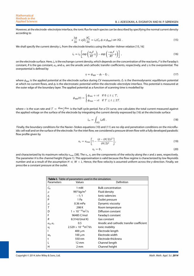
B. J. ADESOKAN, A. EVGRAFOV AND M. P. SØRENSEN
However, at the electrode–electrolyte interface, the ionic flux for each species can be described by specifying the normal current densityaccording to
@
@nC zjDj
@Cj
@nD in.Cj ,, v;app/ on @ . (15)
We shall specify the current density in from the electrode kinetics using the Butler–Volmer relation [15, 16]
in D io
exp
˛aF
RT
exp
˛cF
RT
, (16)
on the electrode surface. Here, io is the exchange current density, which depends on the concentration of the reactants, F is the Faraday’sconstant, R is the gas constant, ˛a and ˛c are the anodic and cathodic transfer coefficients, respectively, and is the overpotential. Theoverpotential is defined by
D app l Ef , (17)
where app is the applied potential at the electrode surface during CV measurements. Ef is the thermodynamic equilibrium potentialat which no current flows, and l is the electrostatic potential within the electrode–electrolyte interface. This potential is measured atthe outer edge of the boundary layer. The applied potential as a function of scanning time is modelled by
app.t/ D
(min C t if 0 t T ,
max t if T t 2T .
where is the scan rate and T D maxmin
is the half cycle period. For a CV curve, one calculates the total current measured againstthe applied voltage on the surface of the electrode by integrating the current density expressed by (16) at the electrode surface
icv D
Z@
indS . (18)
Finally, the boundary conditions for the Navier–Stokes equations (10) and (11) are no-slip and penetration conditions on the microflu-idic cell wall and on the surface of the electrode. For the inlet flow, we considered a pressure driven flow with a fully developed parabolicflow profile given by
vx D vmax
1
.z .H=2//2
.H=2/2
, (19)
vz D 0 , (20)
and characterized by its maximum velocity vmax [38]. The vx , vz are the components of the velocity along the x and z axes, respectively.The parameter H is the channel height (Figure 1). This approximation is valid because the flow regime is characterized by low Reynoldsnumber and as a result of the assumption H W < L. Hence, the flow velocity is assumed uniform across the y-direction. Finally, weprescribe a constant pressure at the outlet.
Table I. Table of parameters used in the simulation.Parameters Values Definition
Cb 1 mM Bulk concentration 997 kg/m3 Fluid densityzj 1=1 Ionic valenciesP 1 Pa Outlet pressure 0.36 mPa Dynamic viscosityT 298 K Room temperatureD 1 1010m2/s Diffusion constantF 96485 C/mol Faraday’s constantR 8.314J/(mol K) Gas constant˛a,˛c 0.5 Anodic and cathodic transfer coefficientuj 2.529 108m2/Vs Ionic mobilityl 400 m Electrode lengthwe 100 m Electrode widtht 550 nm Electrode thicknessL 12 mm Channel lengthH 2 mm Channel height
Copyright © 2014 John Wiley & Sons, Ltd. Math. Meth. Appl. Sci. 2014
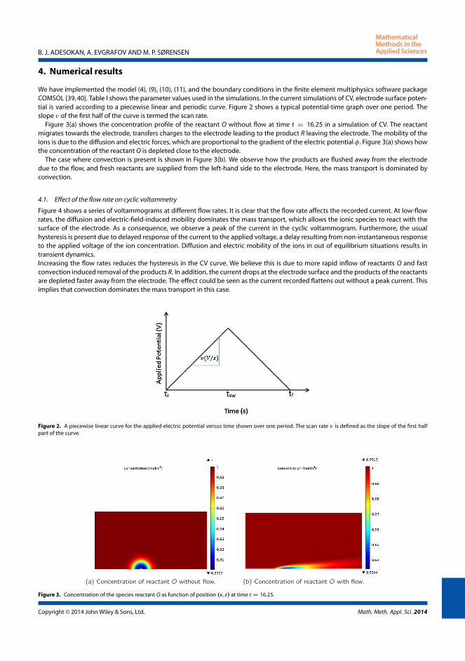
B. J. ADESOKAN, A. EVGRAFOV AND M. P. SØRENSEN
4. Numerical results
We have implemented the model (4), (9), (10), (11), and the boundary conditions in the finite element multiphysics software packageCOMSOL [39, 40]. Table I shows the parameter values used in the simulations. In the current simulations of CV, electrode surface poten-tial is varied according to a piecewise linear and periodic curve. Figure 2 shows a typical potential-time graph over one period. Theslope of the first half of the curve is termed the scan rate.
Figure 3(a) shows the concentration profile of the reactant O without flow at time t D 16.25 in a simulation of CV. The reactantmigrates towards the electrode, transfers charges to the electrode leading to the product R leaving the electrode. The mobility of theions is due to the diffusion and electric forces, which are proportional to the gradient of the electric potential . Figure 3(a) shows howthe concentration of the reactant O is depleted close to the electrode.
The case where convection is present is shown in Figure 3(b). We observe how the products are flushed away from the electrodedue to the flow, and fresh reactants are supplied from the left-hand side to the electrode. Here, the mass transport is dominated byconvection.
4.1. Effect of the flow rate on cyclic voltammetry
Figure 4 shows a series of voltammograms at different flow rates. It is clear that the flow rate affects the recorded current. At low-flowrates, the diffusion and electric-field-induced mobility dominates the mass transport, which allows the ionic species to react with thesurface of the electrode. As a consequence, we observe a peak of the current in the cyclic voltammogram. Furthermore, the usualhysteresis is present due to delayed response of the current to the applied voltage, a delay resulting from non-instantaneous responseto the applied voltage of the ion concentration. Diffusion and electric mobility of the ions in out of equilibrium situations results intransient dynamics.Increasing the flow rates reduces the hysteresis in the CV curve. We believe this is due to more rapid inflow of reactants O and fastconvection induced removal of the products R. In addition, the current drops at the electrode surface and the products of the reactantsare depleted faster away from the electrode. The effect could be seen as the current recorded flattens out without a peak current. Thisimplies that convection dominates the mass transport in this case.
Figure 2. A piecewise linear curve for the applied electric potential versus time shown over one period. The scan rate is defined as the slope of the first halfpart of the curve.
Figure 3. Concentration of the species reactant O as function of position .x, z/ at time t D 16.25.
Copyright © 2014 John Wiley & Sons, Ltd. Math. Meth. Appl. Sci. 2014
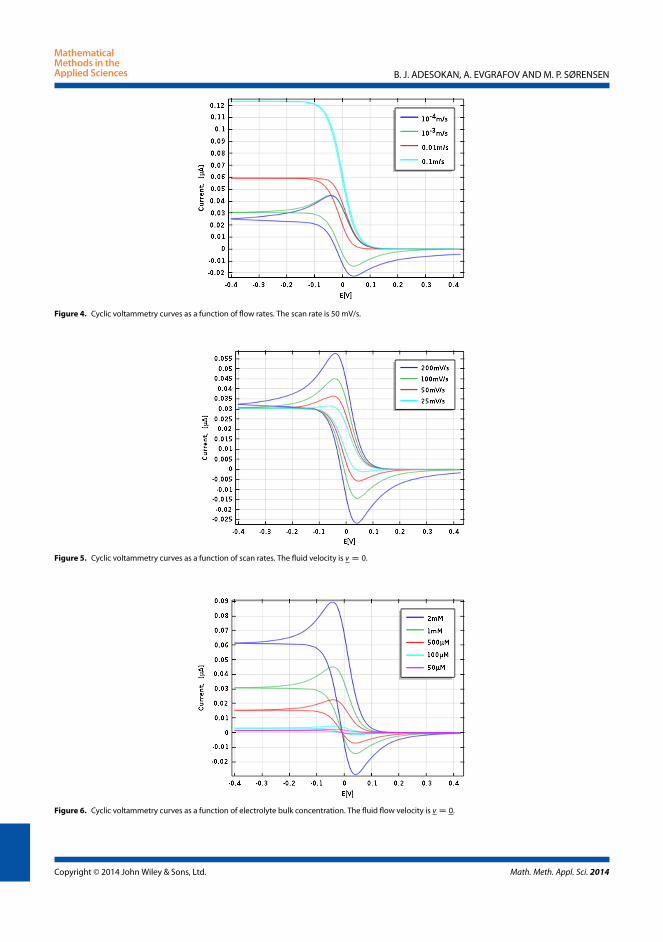
B. J. ADESOKAN, A. EVGRAFOV AND M. P. SØRENSEN
Figure 4. Cyclic voltammetry curves as a function of flow rates. The scan rate is 50 mV/s.
Figure 5. Cyclic voltammetry curves as a function of scan rates. The fluid velocity is v D 0.
Figure 6. Cyclic voltammetry curves as a function of electrolyte bulk concentration. The fluid flow velocity is v D 0.
Copyright © 2014 John Wiley & Sons, Ltd. Math. Meth. Appl. Sci. 2014

B. J. ADESOKAN, A. EVGRAFOV AND M. P. SØRENSEN
4.2. Effect of the scan rate on cyclic voltammetry
In Figure 5, we show simulations of CV current voltage curves at different scan rates but without convective flow. At higher scan rates,the hysteresis becomes more pronounced, caused by the non-instantaneous response of the current to the applied voltage due todiffusion and electric-field-induced mobility of ions.
4.3. Effect of reactant concentration on cyclic voltammetry
Intuitively, we expect that for higher concentration of ions in the electrolyte, higher current values will be recorded. The results inFigure 6 show that the peak current varies linearly with the reactant concentration. The figure also shows that the hysteresis effect isnot influenced by the reactant concentration.
5. Conclusions
We have set up a simple model that describes an electrochemical system from which CV was simulated. The model allows us to inves-tigate the effect of flow rates, scan rates, and concentration on the CV curves. The main results are that higher flow rates lead to thereduced hysteresis in the current voltage curves and increasing scan rates lead to more pronounced current peaks. In the CV currentvoltage characteristics, the current increases proportionally to the electrolyte concentration.
Acknowledgements
We acknowledge financial support from the Villum Kann Rasmussen centre of Excellence: Nano Mechanical Sensors and Actuators,fundamentals and new directions (NAMEC). We thank Messoud Efendiev for very fruitful discussions on the fundamental mathematicalproperties of reaction–diffusion–advection equations and his ever inspiring lectures and visits to our department.
References1. Jimenez-Jorquera C, Orozco J, Baldii A. ISFET based microsensors for environmental monitoring. Sensors 2009; 10:61–83.2. Tsoukalas D, Chatzandroulis S, Goustouridis D. Capacitive Microsensors for Biomedical Applications Encyclopedia of Medical Devices and Instrumenta-
tion. John Wiley & Sons, Inc.: Hoboken, New Jersey, 2006.3. Fritz J. Cantilever biosensors. The Analyst, Milton Road, Cambridge, UK, 2008; 133(7):855–863.4. Jianhong P, Fang T, Thomas T. Glucose biosensor based on the microcantileverm. Analytical Chemistry 2004; 76(2):292–297.5. Si S-H, Huang K-L, Lu C-Y, Yao S-Z. Electrodeless piezoelectric quartz crystal sensor for determination of total urinary reducing sugar. Microchemical
Journal 1999; 62(3):328–335.6. Moulin AM, O’Shea SJ, Welland ME. Microcantilever-based biosensors. Ultramicroscopy 2000; 82:23–31.7. Gruber K, Horlacher T, Castelli R, Mader A, Seeberger PH, Hermann BA. Cantilever array sensors detect specific carbohydrate-protein interactions
with picomolar sensitivity. ACS Nano 2011; 5:3670–3678.8. Hansen KM, Ji H-F, Wu G, Datar R, Cote R, Majumdar A, Thundat T. Cantilever-based optical deflection assay for discrimination of DNA single-
nucleotide mismatches. Analytical Chemistry 2001; 73(7):1567–1571.9. Nugaeva N, Gfeller KY, Backmann N, Lang HP, Düggelin M, Hegner M. Micromechanical cantilever array sensors for selective fungal immobilization
and fast growth detection. Biosensors and Bioelectronics 2005; 21(6):849–856.10. Hwang KS, Lee S-M, Kim SK, Lee JH, Kim TS. Micro- and nanocantilever devices and systems for biomolecule detection. Annual Review of Analytical
Chemistry 2009; 2:77–98.11. Waggoner PS, Craighead HG. Micro- and nanomechanical sensors for environmental, chemical, and biological detection. Lab on A Chip 2007;
7(10):1238–55.12. Grieshabe D, MacKenzie R, Voros J, Reimhult E. Electrochemical biosensors - sensor principles and architectures. Sensors 2008; 8(3):1400–1458.13. Cruys-Bagger N, Badino SF, Tokin R, Gontsarik M, Fathalinejad S, Jensen K, Toscano MD, Sørensen TH, Borch K, Tatsumi H, Väljamäe P, Westh P. A
pyranose dehydrogenase-based biosensor for kinetic analysis of enzymatic hydrolysis of cellulose by cellulases. Enzyme and Microbial Technology2014; 58:68–74.
14. Wang J, Polsky R, Tian B, Chatrathi MP. Voltammetry on microfluidic chip platforms. Analytical Chemistry 2000; 72(21):5285–5289.15. Bard AJ, Faulkner RF. Electrochemical Methods: Fundamentals and Applications 2nd ed. John Wiley & Sons.16. Newmann J, Thomas A, Karen E. Electrochemical Systems 3rd ed. Wiley-Interscience: Hoboken, New Jersey, 2004.17. Compton RG, Banks CE. Understanding Voltammetry 2nd ed. Imperial College Press: Covent Garden, London, 2011.18. Compton RG, Fisher AC, Wellington R, Dobson PJ, Leigh PA. Hydrodynamic voltammetry with microelectrodes: channel microband electrodes;
theory and experiment. The Journal of Physical Chemistry 1993; 97(40):10410–10415.19. Orlik M. Digital simulation of cyclic voltammetry in a two-electrode system and its application to the kinetics of bis(biphenyl)chromium(i) in n,
n-dimethylformamide. Journal of Electroanalytical Chemistry 1997; 434:139–152.20. Orlik M. An improved algorithm for the numerical simulation of cyclic voltammetric curves affected by the ohmic potential drops and its application
to the kinetics of bis(biphenyl)chromium(i) electroreduction. Journal of Electroanalytical Chemistry 2005; 575(2):281–286.21. Yang S, Yang W, Sun G, Knickle H. Secondary current density distribution analysis of an aluminum-air cell. Journal of Power Sources 2006; 161(2):
1412–1419.22. Deng Z-X, Lin X-Q. Digital simulation of fast cyclic voltammogram by integration of the double layer charging current. Journal of Electroanalytical
Chemistry 1999; 464:215–221.
Copyright © 2014 John Wiley & Sons, Ltd. Math. Meth. Appl. Sci. 2014

B. J. ADESOKAN, A. EVGRAFOV AND M. P. SØRENSEN
23. Wain AJ, Compton RG, Le Roux R, Matthews S, Fisher AC. Microfluidic channel flow cell for simultaneous cryoelectrochemical electron spinresonance. Analytical Chemistry 2007; 79(5):1865–1873.
24. Chung M-H. A numerical method for analysis of tertiary current distribution in unsteady natural convection multi-ion electrodeposition. Electrochim-ica Acta 2000; 45(24):3959–3972.
25. Ferrigno R, Brevet PF, Girault HH. Finite element simulation of the amperometric response of recessed and protruding microband electrodes in flowchannels. Journal of Electroanalytical Chemistry 1997; 430(1–2):235–242.
26. Matsuda H, Ayabe Y. On the theory of the randles-sevcik cathode-ray polarography. Z. Electrochemistry 1955; 59:494–503.27. Nicholson RS, Shain I. Theory of Stationary Electrode Polarography. Single Scan and Cyclic Methods Applied to Reversible, Irreversible, and Kinetic
Systems. Anal. Chem. 1964; 36(4):70–723.28. Feldberg SW, Bard AJ. Electroanalytical Chemistry. Marcel Dekker: New York, 1969.29. Feldberg SW, Mattson JS, Mark HB, MacDonald HC,Jr. Computers in Chemistry and Instrumentation. Marcel Dekker: New York, 1972.30. Szabo A, Shoup D. Chronoamperometric current at finite disk electrodes. Journal of Electroanalytical Chemistry 1982; 140:237–245.31. Batchelor GK. An Introduction to Fluids Dynamics. Cambridge University Press: Cambridge, 1967.32. Fuhrmann J, Linke A, Langmach H. A numerical method for mass conservative coupling between fluid flow and solute transport. Applied Numerical
Mathematics 2011; 61:530–553.33. Kilic MS, Bazant MZ. Steric effects in the dynamics of electrolytes at large applied voltages. ii. Modified Poisson-Nernst-Planck equations. Physical
Review E 2007; 75:1–11.34. Efendiev MA. Evolution Equations Arising in the Modelling of Life Sciences. Birkhäser: Basel, 2013.35. Sonner S, Efendiev MA, Eberl HJ. On the well-posedness of a mathematical model of quorum-sensing in patchy biofilm communities. Mathematical
Methods in the Applied Sciences 2011; 34:1667–1684.36. Efendiev MA. Attractors for Degenerate Parabolic Type Equations, Vol. 192. Mathematical Surveys and Monographs, American Mathematical Society,
2013.37. Quan X, Fischer Lee M, Boisen A, Tenje M. Development of nanoporous gold electrodes for electrochemical applications. Microelectronic Engineering
2011; 88:2379–2382.38. Bird RB, Stewart WE, Lightfoot EN. Transport Phenomena, Revised 2nd Edition 2nd ed. John Wiley & Sons, Inc.: New York, 2002.39. Zimmerman WBJ. Multiphysics Modelling with Finite Elements Methods. World Scientific Publishing Co.: Singapore, 2006.40. Comsol®multiphysics finite element analysis software.
Copyright © 2014 John Wiley & Sons, Ltd. Math. Meth. Appl. Sci. 2014

52 Numerical modeling of Electroanalytical techniques

Chapter 5
Experimentation andNumerical Modeling of
Cyclic Voltammetry
Paper II

Experimentation and Numerical Modeling of CyclicVoltammetry for Electrochemical Micro-sized Sensors
under the Influence of Electrolyte Flow
B. J. Adesokana, X. Quanb, A. Evgrafova, A. Heiskanenb, A. Boisenb, M. P.Sørensena,∗
aDepartment of Applied Mathematics and Computer Science, Technical University ofDenmark, Richard Petersens Plads, Building 324, 2800 Kgs. Lyngby, Denmark
bDepartment of Micro and Nanotechnology, Technical University of Denmark, Building345E, Ørsteds Plads, 2800 Kgs. Lyngby, Denmark
Abstract
We investigate the effect of flow rate and scan rate on cyclic voltammetry in
a microfluidic system for two different electrode locations. The mathematical
model is based on ion transport governed by the Nernst-Planck equations cou-
pled to the Navier-Stokes equations for hydrodynamics. The Butler-Volmer re-
lation provides the boundary conditions which represent reaction kinetics at the
electrode-electrolyte interface. The result shows that convection influences the
charge transfer dynamics on the electrode surface and hence the cyclic voltam-
metry recorded. In terms of relative flow and scan rates, the current response
is limited by the convection due to the supply of fresh ions at the electrode
surface and quick removal of the products. However, at a high scan rates and a
modest flow rates, peak current are recorded. The model also allows predicting
the effect of varying electrolyte concentration and scan rates respectively. The
numerical results with experimental findings, demonstrate qualitative and often
also quantitative agreement.
Keywords: Cyclic Voltammetry, Microelectrode Location, Nernst-Planck,
Navier-Stokes, Finite Element Method
∗M. P. SørensenEmail address: [email protected] (M. P. Sørensen )
Preprint submitted to Journal of Electrochimica ACTA December 17, 2014
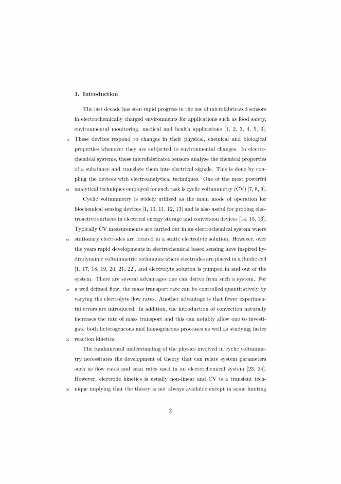
1. Introduction
The last decade has seen rapid progress in the use of microfabricated sensors
in electrochemically charged environments for applications such as food safety,
environmental monitoring, medical and health applications [1, 2, 3, 4, 5, 6].
These devices respond to changes in their physical, chemical and biological5
properties whenever they are subjected to environmental changes. In electro-
chemical systems, these microfabricated sensors analyse the chemical properties
of a substance and translate them into electrical signals. This is done by cou-
pling the devices with electroanalytical techniques. One of the most powerful
analytical techniques employed for such task is cyclic voltammetry (CV) [7, 8, 9].10
Cyclic voltammetry is widely utilized as the main mode of operation for
biochemical sensing devices [1, 10, 11, 12, 13] and is also useful for probing elec-
troactive surfaces in electrical energy storage and conversion devices [14, 15, 16].
Typically CV measurements are carried out in an electrochemical system where
stationary electrodes are located in a static electrolyte solution. However, over15
the years rapid developments in electrochemical based sensing have inspired hy-
drodynamic voltammetric techniques where electrodes are placed in a fluidic cell
[1, 17, 18, 19, 20, 21, 22], and electrolyte solution is pumped in and out of the
system. There are several advantages one can derive from such a system. For
a well defined flow, the mass transport rate can be controlled quantitatively by20
varying the electrolyte flow rates. Another advantage is that fewer experimen-
tal errors are introduced. In addition, the introduction of convection naturally
increases the rate of mass transport and this can notably allow one to investi-
gate both heterogeneous and homogeneous processes as well as studying faster
reaction kinetics.25
The fundamental understanding of the physics involved in cyclic voltamme-
try necessitates the development of theory that can relate system parameters
such as flow rates and scan rates used in an electrochemical system [23, 24].
However, electrode kinetics is usually non-linear and CV is a transient tech-
nique implying that the theory is not always available except in some limiting30
2

cases. Hence, numerical simulation is necessary. Furthermore, numerical solu-
tions along with experimental methods allow for the effective study of parame-
ters that characterize the output of a cyclic voltammetry measurement in more
details.
Numerical solutions of the CV was first introduced by Feldberg [25, 26].35
Since then several other authors have numerically studied CV with diffusion as
the only mode of mass transfer, see for example [27, 28, 29]. Furthermore, there
is an extensive list of authors that have numerically simulated CV curves in
a flowing stream, in particular the Compton’s group [19, 30, 31, 32, 33]. The
authors among others have employed numerical methods such as the alternat-40
ing direction implicit (ADI), strongly implicit procedure (SIP), the backwards
implicit (BI) method, hopscotch algorithm [34, 35, 36] with regular meshes
which may results in poor spatial convergence. Furthermore in order to ease
the computational procedure, simplifications are made to the specified bound-
ary conditions. For example, a constant concentration over the electrode surface45
can be specified. This corresponds to the limiting current which is the highest
mass transfer rate. Although these boundary conditions simplify the solution
of ion transport problem from which the CV is computed, the applications of
the calculated solutions are consequently limited and should be ascertained by
comparing them with experimental data. Motivated by the design and opti-50
mization of the electrode to ensure accurate CV measurement and for better
characterisation of the response signal in an electrochemical system, we seek a
solution method that can handle complex geometry which also allows for high
computational flexibility and maintain the stability properties of the method
deployed.55
This study focuses on simulating CV using a flexible but powerful finite ele-
ment method (FEM) solver, Comsol Multiphysics, under appropriate boundary
conditions and electrode configurations in a microfluidic channel. In particular
we investigate cantilever electrodes mounted in a microfluidic cell. We inves-
tigate the effect of flow rates, scan rates as well as electrolyte concentration60
and compare simulations to experimental data recorded for a CV measurement
3

under different electrode configurations. We demonstrate that the location of
electrodes in an electrochemical system plays a significant role while recording a
CV measurement. This information will be utilized to understand the behaviour
of an electrochemical system needed in designing micro electrochemical sensors65
with improved performance.
2. Experimental setup of the electrochemical cantilever sensor
The electrochemical cantilever sensor (ECC) chip presented here was fab-
ricated by standard microfabrication processes [17]. As shown in Figure 1,
the chip has dimension 12mm × 11.3mm and it was fabricated on a 375µm70
thick Si substrate. Four cantilevers were placed in the middle of the chip, each
having the dimensions 100 µmm(width) × 550 nm (thickness) × 400 µm(length).
Each cantilever was capable of functioning as an independent working electrode
(WE). The reference electrode with dimensions 100µm × 200µm was placed
on the right side of the cantilevers and the counter electrode with dimensions75
2700µm × 400µm on the left side. All the electrodes were coated using e-beam
evaporation with a 2 nm chrome adhesion layer followed by 30 nm of gold. The
chips were cleaned before use. They were immersed in a piranha solution for
6min, and then rinsed thoroughly in MilliQ-water and ethanol [37]. Finally, the
chips were blown dry with nitrogen gas and mounted in a microfluidic chamber.80
As shown in Figure 1, the microfluidic chamber encapsulates the ECC biosensor
with a volume of approximately 105µL and creates a flow path leading into the
chip and through the channel past the cantilevers. The fluid enters from the side
of the reference electrode and exits from the counter electrode side. There was
an access to install a reference electrode in the microfluidic chamber as well. The85
system was connected to a syringe pump (PHD 2000 Infuse/Withdraw syringe
pump, Harvard Apparatus, USA) and set the flow rates of up to 600µL/min.
4

Figure 1: Fluidic cell and layout of a biosensor chip.
The electrolyte with active redox probes used in the cyclic voltammetric
measurements consists of 200 mM KNO3 solutions with 2mM of K3Fe(CN)6
in Milli-Q water. All the chemicals were used without further purification. A90
DRIREF-2SH Ag/AgCl reference electrode was applied in the three-electrode
electrochemical cell. Cyclic voltammetry was performed using a computer con-
trolled CHI1030 Potentiostat.
5
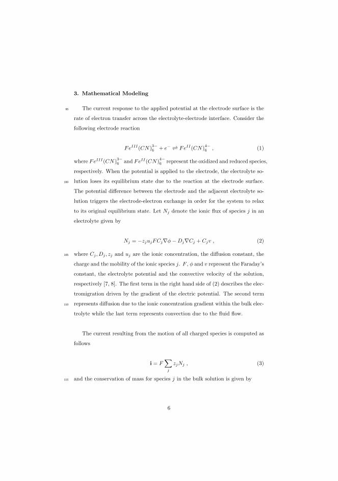
3. Mathematical Modeling
The current response to the applied potential at the electrode surface is the95
rate of electron transfer across the electrolyte-electrode interface. Consider the
following electrode reaction
FeIII(CN)3−6 + e− FeII(CN)
4−6 , (1)
where FeIII(CN)3−6 and FeII(CN)
4−6 represent the oxidized and reduced species,
respectively. When the potential is applied to the electrode, the electrolyte so-
lution loses its equilibrium state due to the reaction at the electrode surface.100
The potential difference between the electrode and the adjacent electrolyte so-
lution triggers the electrode-electron exchange in order for the system to relax
to its original equilibrium state. Let Nj denote the ionic flux of species j in an
electrolyte given by
Nj = −zjujFCj∇ϕ − Dj∇Cj + Cjv , (2)
where Cj , Dj , zj and uj are the ionic concentration, the diffusion constant, the105
charge and the mobility of the ionic species j. F , ϕ and v represent the Faraday’s
constant, the electrolyte potential and the convective velocity of the solution,
respectively [7, 8]. The first term in the right hand side of (2) describes the elec-
tromigration driven by the gradient of the electric potential. The second term
represents diffusion due to the ionic concentration gradient within the bulk elec-110
trolyte while the last term represents convection due to the fluid flow.
The current resulting from the motion of all charged species is computed as
follows
i = F∑
j
zjNj , (3)
and the conservation of mass for species j in the bulk solution is given by115
6

∂Cj
∂t= −∇ · Nj . (4)
Here, we assume there is no chemical reaction within the bulk.
We shall assume that the electrolyte solution is electrically neutral except at
a very thin electric double layer close to the electrode. In our analysis, we have
neglected the thin layer and assumed electroneutrality throughout the solution.120
For an electrically neutral solution, the following holds
∑
j
zjCj = 0 . (5)
From equation (4) and the electronuetrality condition (5), conservation of elec-
tric current can be derived
∇ · i = 0 . (6)
The equation for the electric potential
∇ · (κ∇ϕ) + F∑
j
zj∇ · Dj∇Cj = 0 , (7)
can easily be derived from equation (6) by using the electronuetrality condition125
(5). Here κ = F 2∑
j z2j ujCj is the electrolyte conductivity.
Equations (4) and (7) couple the electric potential and ionic concentration
of the system. Finally, in order to close the system, we need to determine the
velocity field v of the electrolyte. This can be done by solving the Navier-Stokes
equations for incompressible flow,130
∇ · v = 0 , (8)
ρ
(∂v
∂t+ v · ∇v
)= −∇p + µ∇2v + sf . (9)
The fluid density is denoted ρ, p is the pressure, µ is the dynamic viscosity and
finally sf denotes an external force per unit volume [38, 39]. Finally, equations
(4), (7), (8) and (9) must be solved with appropriate boundary conditions.
7

3.1. Boundary conditions and computational domain
In order to facilitate the numerical simulation of the micro fluidic cell de-135
picted in Figure 1, we will restrict our computational domain to cover a vol-
ume including the cantilever electrodes and a neighborhood of the electrodes
in the electrolyte. At the left boundary of the computational domain we use
inflow conditions and at the right boundary we use outflow conditions, chosen
as close as possible to the experimental situation. Hereby we substantially re-140
duce the computational task in comparison to simulating the entire microfluidic
cell. Specifically, we chose the computational domain in Figure 2, which is small
enough to facilitate the computational task yet sufficiently complex to provide
comprehensive insight into the influence of the convective flow, scan rates and
concentration of reactants on cyclic voltammetry for the cell shown in Figure 1.145
In what follows, we shall specify the boundary conditions for the computational
domain having length L, width W and height H. The computational domain in
Figure 2 encompass the working electrode of width we and length ℓ placed at
the center of the domain but fixed to the wall of the domain anywhere between
z = 0 and z = H. The counter electrode is placed far to the left of the working150
electrode and is not shown in the figure.
computational domain
l
C jWe
flowW
L
H
y
x
z
Figure 2: Schematic diagram of the fluidic channel and a micro-sized working
electrode
The counter electrode allows the current flowing through the electrolyte
solution via the working electrode to leave the solution. In addition, we may
8

insert a reference electrode in order to maintain a stable and constant potential
at the working electrode. There is normally no current flow passing through155
the reference electrode. Furthermore, we consider a cell where H ≪ W < L
and accordingly we assume that transport of ions and fluidic motion can be
considered two dimensional. This means we restrict our model to the cross
sectional xz-plane at any point on y away from the walls at y = 0 and y = W
in Figure 2.160
The potential-current responses are measured at the surface of the electrode
- at least within the thin layer above the electrode and hence the boundary
conditions play a central role in modeling cyclic voltammetry. At the inlet we
specify constant concentrations of the chemical species and a no flux boundary
condition −n·Nj = 0 on the fluidic cell walls where n is the unit normal pointing165
towards the electrolyte. At the outlet of the cell we specify D∂Cj
∂n= 0. At the
insulating surfaces ∂Ωins there are no current flow which means that the normal
current density in across such a boundary is zero, that is
in = 0 on ∂Ωins. (10)
In other words, from the conservation of the electric current (7) we can
prescribe Neumann type boundary conditions170
κ∂ϕ
∂n= −zjDj
∂Cj
∂non ∂Ωins . (11)
However, at the electrode surface the ionic flux for each species j can be modeled
by the normal current density determined from electrode kinetics,viz
κ∂ϕ
∂n+ zjDj
∂Cj
∂n= in(Cj , ϕ, v; ϕapp) on ∂Ω . (12)
Here ϕapp is the applied potential on the electrode surface.
The electrode kinetics we shall model by the Butler-Volmer relation [7, 8,175
40, 41],
9

in = io
[CR exp
(αaF
RTηs
)− CO exp
(−αaF
RTηs
)], (13)
where
η = ϕapp − ϕl − Ef , (14)
is the overpotential, which defines the potential difference between the electrode
and the adjacent electrolyte solution. Ef is the thermodynamic equilibrium
potential at which no current flows and ϕl is the electrostatic potential within180
the electrode-electrolyte interface. This potential is measured at the outer edge
of the concentration boundary layer. The applied potential as a function of
scanning time can be modeled as follows,
ϕapp(t) =
ϕmin + νt if 0 ≤ t ≤ Tϕmax − νt if T ≤ t ≤ 2T
where ν is the scan rate and T =ϕmax − ϕmin
νis the half cycle period.
For a cyclic voltammetry curve, one computes the total current response to185
the applied potential on the surface of the electrode by integrating the current
density expressed in (13) at the electrode surface ∂Ω
icv =
∫
∂Ω
indS . (15)
Finally, the boundary conditions for the Navier-Stokes equations (8) and(9) are
no-slip and no penetration conditions at the fluidic cell wall and at the surface
of the electrode. For the inlet flow, we considered a pressure driven flow with a190
fully developed parabolic flow profile
vx = vmax
[1 − (z − (H/2))2
(H/2)2
], (16)
vz = 0 , (17)
characterized by its maximum velocity vmax [42, 43]. The vx and vz are the
components of the velocity along the x and z axis, respectively. vmax is the
10

maximum velocity at the tip of the parabola. This approximation is valid be-
cause the flow regime is characterized by low Reynolds number and the width195
of the fluidic cell in the y-direction is far larger than the height H. Hence, the
velocity flow is uniform across the y-direction. The volumetric flow rate U is
calculated from the input velocity through
U = vxHW , (18)
where W is the width of the fluidic cell and
vx =1
H
∫ H
0
vxdy =2
3vmax (19)
is the average velocity [44]. At the outlet, we specify a constant pressure value.200
4. Numerical methods and parameters
We solved numerically the test problem using the commercial software pack-
age COMSOL Multiphysics [45, 46] on a Windows work station (Core i7 CPU,
4 cores, 2.40GHz, 16.0GB RAM). The geometries are shown in Figure 3. They
consist of the flow ducts with two configurations for the electrodes. We consider205
a case where the electrode is placed at the bottom of the cell and the case where
it is placed in the center of the cell. In both cases the electrodes are fixed to the
cell wall. We have simulated a 2D approximation to the full system in Figure 2.
l
Ω∂ ins
Ω∂ ins
te
(a)
Ω∂ ins
Ω∂ ins
tel
(b)
Figure 3: Computational domain with different electrode configurations. (a)
center placed, (b) bottom placed.
11

We employed a two step approach in solving the coupled fluid and ion-
transport problem. First, we find a steady state solution to the incompressible210
Navier-Stokes equations.
−0.2 0 0.2 0.4 0.6−0.1
0
0.1
0.2
Potential(V)
Cur
rent
(µA
)
7000 Elements34000 Elements57000 Elements
Figure 4: The computations are conducted for the fluid cell geometry in Figure
3b.
The steady state velocity is then substituted into the ion transport problem.
We solved the fluid flow problem by discretizing the computational domain using
the linear Lagrange finite elements for the pressure field and quadratic elements
for the velocity field. In addition, we have utilized quadratic elements for the215
ion transport problem [39, 46, 45].
In order to assess the accuracy of the solution method, we performed several
studies based on finer and finer meshes until there are only small changes in the
estimated current-potential curves, Figure 4 are observed. The high density of
mesh is due to local mesh refinement around the electrode where there are large220
solution gradients. In order to ensure a good compromise between computa-
tional time and the accuracy of the results we have used about 35000 elements
in our computations. For the time integration, we have employed implicit Euler
method. Table 1 shows the parameters used throughout in the simulation.
12

(a) (b)
Figure 5: The Concentration of FeIII(CN)3−6 showing the effect of the flow
pattern on the electrode position. The flow rate is 250µL/min.
5. Results and Discussion225
Figures 5a and 5b show a snapshot of the concentration of FeIII(CN)3−6
taken at time t = 16.25 s, that is at the final time of one scan with 50 mV/s
scan rate. For the center placed electrode in Figure 5a, the concentration of
FeIII(CN)3−6 downstream of the cantilever electrode is slightly lower than the
upstream concentration. As the concentration is high close to the electrode230
we may expect higher currents. For the bottom placed electrode in Figure 5b
the electrolyte flow velocity is very small close to the bottom surface. This
suggests that mass transport due to convection is limited and that mass flow
is dominated by diffusion and the electric forces, which means fewer electro
active species are brought towards the electrode surface for the bottom placed235
electrode. However, for the center placed electrode, electro active species are
brought fast to the electrode surface.
13

Parameters Values Definition
l 400µm electrode length
we 100µm electrode width
te 550nm electrode thickness
L 12mm channel length
H 1mm channel height
Cb 2mM bulk concentration
ρ 997kg/m3 fluid density
µ 0.36mPa dynamic viscosity
P 1Pa outlet pressure
T 298K room temperature
ν (50 - 250)mV/s scan rates
D 1 × 10⁻¹⁰m2s diffusion constant
F 96485C/mol Faraday’s constant
R 8.314J/(mol K) gas constant
αa,αc 0.5 anodic and cathodic transfer coefficients
uj 2.529 × 10⁻⁸m2/V s ionic mobility
U (50 − 250)µL/min volumetric flow rates
Table 1: Cell dimensions and other parameters used in the simulations.
5.1. Cyclic voltammetry in a static electrolyte
In order to validate the model, we perform experiments and simulations
using a static electrolyte by varying the bulk concentration from 500µM to240
2mM before flow is introduced into the respective systems. In Fig. 6, we show
the plots of the current (µA) against potential E(v) for forward and reverse
scans performed between 0.6 V and -0.2 V. Note here that both experiments
and simulation were performed at a scan rate of 50mV/s.
Focusing on the experimental results presented in Fig. 6a, a first observation245
for all concentrations is that the peak current is reached before the end of the
14
forward scan. Interestingly, for all concentrations, the anodic peak current is
reached at a potential E ≈ 0.25 V. This indicates a non-dependence of the
peak potential reached on the concentration. Secondly, we observe that the
current recorded at end of the forward scan E = -0.2 V is higher with increasing250
concentration, even though they were all initiated at zero current. During the
reverse scan, a non-symmetric evolution of the current is seen with respect to the
forward scan. The non-symmetry of the current is possibly a feature arising from
the non-symmetric range of potential chosen. The minimum current is reached
at a higher potential E ≈ 0.35 V and is also independent of concentration. At255
the end of the reverse scan, the initial state is not recovered, indicating hysteretic
and memory effects.
In Fig. 6b, we plot the corresponding numerical results of the experiment
described above. For the sake of brevity, we note that qualitative features re-
ported for experiments, namely the independence of potential at peak current260
and increase in current at the end of the forward scan with increasing concen-
tration are well captured by the simulation. Slight quantitative differences in
the anodic peak current reached in simulation and the current obtained at the
end of the forward scans are possibly due to the dimensionality of the current
simulations.265
15

−0.2 0 0.2 0.4 0.6−0.1
0
0.1
0.2
Potential (V)
Cur
rent
(µA
)
2mM1mM500µM
(a)
−0.2 0 0.2 0.4 0.6
−0.1
0
0.1
0.2
Potential (V)
Cur
rent
(µA
)
2mM1mM500µM
(b)
Figure 6: Comparison of a) experimental and b) simulation results of steady-
state cyclic voltammograms as a function of concentration recorded at a center
placed microelectrode in a solution of 200mM KNO3 with K3Fe(CN)6 of a
static electrolyte. Other parameter values taken from Table 1.
5.2. The effect of flow rates on cyclic voltammetry measurements at a micro-
sized electrode
In Figure 7a we show experimental voltammograms at different flow rates
compared to numerical simulations depicted in Figure 7b for an electrode po-
sitioned in the center of the flow chamber with 50 mV/s scan rate. As both270
the experiments and the simulations suggest, flow rates clearly affect the cur-
rent recorded during voltammetry measurements. At low flow rates of (50 −150)µL/min, the results suggest that the ionic mass transport is dominated
by the diffusion of the ionic species towards the working electrode. This en-
sures that even at a slow scan rate of 50mV/s we record enough peak currents275
shown in Figure 7b. However, as the flow rate increases, the hysteresis of the
voltammograms diminishes and the appearance of peak currents becomes less
pronounced. For higher flow rates of 250µL/min the mass transport due to con-
vection dominates that due to diffusion. We believe that the higher flow rates
lead to fresh supply of FeIII(CN)3−6 at high concentration to the electrode and280
16

hence the current increases, in particular at voltage values less than about 0.2V
as is evident in Figure 7.
−0.2 0 0.2 0.4 0.6−0.1
0
0.1
0.2
Potential (V)
Cur
rent
(µA
)
250µL/min150µL/min50µL/min
(a)
−0.2 0 0.2 0.4 0.6−0.1
0
0.1
0.2
Potential (V)
Cur
rent
(µA
)
250µL/min150µL/min50µL/min
(b)
Figure 7: Comparison of a) experimental and b) simulation results of cyclic
voltammograms as a function of flow rates recorded at a centre placed micro-
electrode in a solution of 200mM KNO3 with K3Fe(CN)6. The scan rate is
50mV/s. Other parameter values taken from Table 1.
−0.2 0 0.2 0.4 0.6
−0.1
0
0.1
0.2
Potential (V)
Cur
rent
(µA
)
250µL/min150µL/min50µL/min
Figure 8: Effect of flow rates - Simulation with electrode at the bottom of the
cell. Scan rate at 50mV/s. Other parameter values taken from Table 1.
In Figure 8 we show simulations of cyclic voltammetry for a microfluidic
17
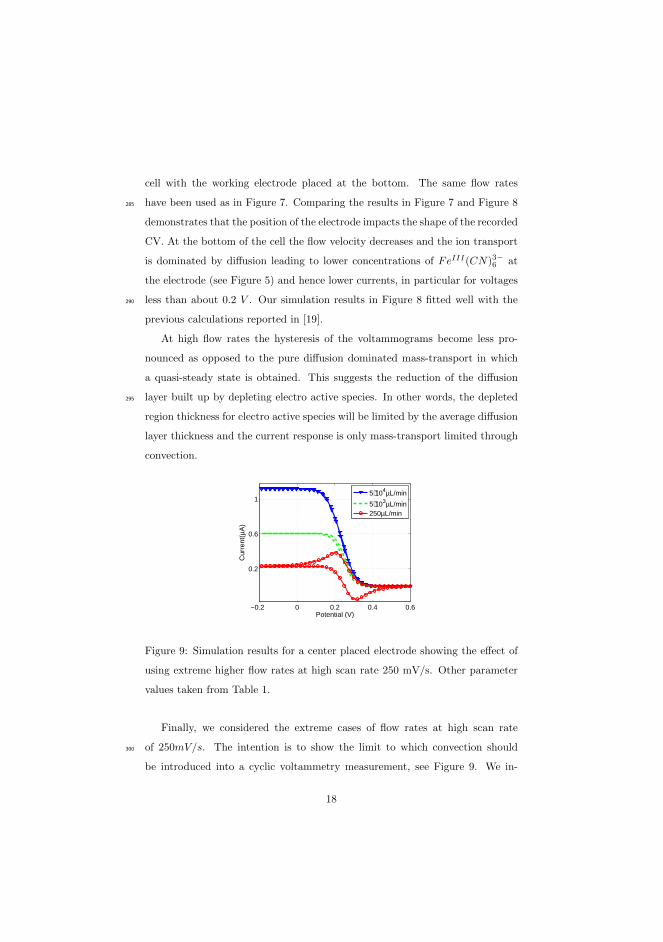
cell with the working electrode placed at the bottom. The same flow rates
have been used as in Figure 7. Comparing the results in Figure 7 and Figure 8285
demonstrates that the position of the electrode impacts the shape of the recorded
CV. At the bottom of the cell the flow velocity decreases and the ion transport
is dominated by diffusion leading to lower concentrations of FeIII(CN)3−6 at
the electrode (see Figure 5) and hence lower currents, in particular for voltages
less than about 0.2 V . Our simulation results in Figure 8 fitted well with the290
previous calculations reported in [19].
At high flow rates the hysteresis of the voltammograms become less pro-
nounced as opposed to the pure diffusion dominated mass-transport in which
a quasi-steady state is obtained. This suggests the reduction of the diffusion
layer built up by depleting electro active species. In other words, the depleted295
region thickness for electro active species will be limited by the average diffusion
layer thickness and the current response is only mass-transport limited through
convection.
−0.2 0 0.2 0.4 0.6
0.2
0.6
1
Potential (V)
Cur
rent
(µA
)
5⋅104µL/min
5⋅103µL/min250µL/min
Figure 9: Simulation results for a center placed electrode showing the effect of
using extreme higher flow rates at high scan rate 250 mV/s. Other parameter
values taken from Table 1.
Finally, we considered the extreme cases of flow rates at high scan rate
of 250mV/s. The intention is to show the limit to which convection should300
be introduced into a cyclic voltammetry measurement, see Figure 9. We in-
18

creased the volumetric flow rate to as high as 104µL/min. The hysteresis of the
voltammograms vanishes completely at the highest flow rate. This implies that
compromise must be made as to what flow rates and scan rates are admissible
depending on the object of interest in the voltammetry study.305
5.3. The effect of scan rates on cyclic voltammetry measurements at a micro-
sized electrode
Depending on the direction of scan, oxidation or reduction, it is expected that
at high scan rates one records the highest current response in voltammetry. This
is indeed observed in Figure 10a where we sweep the potential from 0.6V to -0.2V310
at different scan rates and at a fixed volumetric flow rate of 250µL/min. The
associated simulation results are depicted in Figure 10b, which demonstrate fair
agreement with the experimental measurements but deviates at more negative
and more positive potentials. As expected, the current response increases with
scan rate. At the scan rate of 250mV/s, the peak currents are observed in both315
directions of scan while at 50mV/s a diminished hysteresis is recorded.
−0.2 0 0.2 0.4 0.6
−0.1
0
0.1
0.2
0.3
0.4
Potential(V)
Cur
rent
(µA
)
250[mV/s]150[mV/s]50[mV/s]
(a)
−0.2 0 0.2 0.4 0.6
−0.1
0
0.1
0.2
0.3
0.4
Potential (V)
Cur
rent
(µA
)
250[mV/s]150[mV/s]50[mV/s]
(b)
Figure 10: Comparison of a) experimental and b) simulation results of cyclic
voltammograms as a function of scan rates recorded at a centre placed micro-
electrode in a solution of 200mM KNO3 with 2mM K3Fe(CN)6 with flow rate
of 250 µL/min. Other parameter values taken from Table 1.
19
The peak at high scan rates recorded at the flow rate of 250µL/min can
be explained since at high scan rates surface kinetics is fast enough for elec-
tron exchange to occur before fresh electro-active ions are brought onto and the
products are washed away from the electrode surface. When the potential is320
scanned from positive to negative potentials, the reactants lose electrons fast
enough leading to the increase in current response. The products then deplete
away from the electrode surface. At low scan rates, e.g 50mV/s, current is
controlled mainly by diffusion and convection of the reactant to the electrode
surface. However, at high flow rates, convection increases relative to diffusion325
and fresh reactants are brought to the electrode surface. In addition, because
of the slow scan, electrode surface kinetics is not fast enough for the electron
exchange to record a peak current and hence the narrow and flattened voltam-
mograms as shown in Figure 10b. Comparison between the experimental data
and the simulation results show a very good agreement. See Figure 10a.330
6. Conclusions
The above results show the successful model of a two step finite element
method for simulating cyclic voltammetry under flow conditions. We found that
the flow rates has a strong influence on the current response recorded during
cyclic voltammetry. At high flow rates, a peak current disappears and the hys-335
teresis is reduced while at low rates steady current response with peak current
is recorded. In addition, the placement of electrodes is critical when perform-
ing cyclic voltammetry under flow. The main difference between the centered
placed electrode and the bottom placed electrode is the delay in the conversion
of the fresh ionic species brought to the electrode surface for the bottom placed340
electrode. In the centered placed electrode the influence is more apparent since
the variation can be seen in the current response. We were able to identify the
characteristics of the hydrodynamic effect on the the dynamics of the current
response to the applied voltage in cyclic voltammetry measurements. Qualita-
tive and often also quantitative agreement are found between experimental and345
20

theoretical predictions for cyclic voltammetry measurements. For the design
and optimization of the electrodes, investigation of a full 3D problem is needed.
In addition, since electroneutrality condition does not hold at the electric double
layer (EDL) one can extend the present model by including the phenomenon in
order to capture the complete Physics at the electrode-electrolyte interface.350
7. Acknowledgement
We aknowledge financial support from the Villum Kann Rasmussen centre
of Excellence: Nano Mechanical Sensors and Actuators, fundamentals and new
directions (NAMEC).
References355
[1] L. M. Fischer, C. Pedersen, K. Elkjær, N. N. Noeth, S. Dohn, A. Boisen,
M. Tenje, Development of a microfabricated electrochemical-cantilever hy-
brid platform, Sens. Act. B: Chem. 157 (1) (2011) 321–327.
[2] A. Subramanian, P. I. Oden, S. J. Kennel, K. B. Jacobson, R. J. Warmack,
T. Thundat, M. J. Doktycz, Glucose biosensing using an enzyme-coated360
microcantilever, Appl. Phys. Lett. 81 (2) (2002) 385–387.
[3] K. S. Hwang, S.-M. Lee, S. K. Kim, J. H. Lee, T. S. Kim, Micro- and
nanocantilever devices and systems for biomolecule detection, Annu. Rev.
Anal. Chem. 2 (2009) 77–98.
[4] M. Alvarez, A. Calle, J. Tamayo, L. M. Lechuga, A. Abad, A. Montoya,365
Development of nanomechanical biosensors for detection of the pesticide
DDT, Biosens. Bioelectron. 18 (56) (2003) 649 – 653.
[5] S. P. A. Fodor, R. P. Rava, X. C. Huang, A. C. Pease, C. P. Holmes, C. L.
Adams, Multiplexed biochemical assays with biological chips, Nature 364
(1993) 555 – 556.370
21

[6] X. Quan, L. M. Fischer, A. Boisen, M. Tenje, Development of nanoporous
gold electrodes for electrochemical applications, Microelectron. Eng. 88 (8)
(2011) 2379–2382.
[7] A. J. Bard, L. R. Faulkner, Electrochemical Methods: Fundamentals and
Applications, 2nd Edition, John Wiley & Sons, 2001.375
[8] J. Newmann, K. E. Thomas-Alyea, Electrochemical Systems, 3rd Edition,
Wiley-Interscience, 2004.
[9] R. G. Compton, C. E. Banks, Understanding Voltammetry, 2nd Edition,
World Scientifice, 2011.
[10] S. Chevion, M. Hofmann, R. Ziegler, M. Chevion, P. P. Nawroth, The380
antioxidant properties of thioctic acid: characterization by cyclic voltam-
metry, Biochem. Mol. Biol. Int.l 41 (2) (1997) 317–327.
[11] S. Chevion, M. A. Roberts, M. Chevion, The use of cyclic voltammetry
for the evaluation of antioxidant capacity, Free Radical Biol. Med. 28 (6)
(2000) 860–870.385
[12] D. Grieshaber, R. MacKenzie, J. Voros, E. Reimhult, Electrochemical
biosensors - sensor principles and architectures, Sensors 8 (3) (2008) 1400–
1458.
[13] N. Cruys-Bagger, S. F. Badino, R. Tokin, M. Gontsarik, S. Fathaline-
jad, K. Jensen, M. D. Toscano, T. H. Sørensen, K. Borch, H. Tatsumi,390
P. Valjamae, P. Westha, A pyranose dehydrogenase-based biosensor for ki-
netic analysis of enzymatic hydrolysis of cellulose by cellulases, Enzyme
Microb. Technol. 58 (2014) 68 – 74.
[14] M. Takahashi, S. Tobishima, K. Takei, Y. Sakurai, Reaction behavior of
LiFePO4 as a cathode material for rechargeable lithium batteries, Solid395
State Ionics 148 (2002) 283–289.
22

[15] W. Sugimoto, K. Aoyama, T. Kawaguchi, Y. Murakami, Y. Takasu, Ki-
netics of CH3OH oxidation on PtRu/C studied by impedance and CO
stripping voltammetry, J. Electroana. Chem. 576 (2) (2005) 215–221.
[16] X. Cheng, B. Yi, M. Han, J. Zhang, Y. Qiao, J. Yu, Investigation of plat-400
inum utilization and morphology in catalyst layer of polymer electrolyte
fuel cells, J. Power Sources 79 (1) (1999) 75–81.
[17] X. Quan, A. Heiskanen, Y. Sun, A. Labuda, A. Wolff, J. Jorge Dulanto,
P. Grutter, M. Tenje, A. Boisen, Development of electrochemical cantilever
sensors for dna applications, ECS Transactions 50 (12) (2013) 77–81.405
[18] J. A. Cooper, R. G. Compton, Channel electrodes - a review, Electroanal-
ysis 10 (3) (1998) 141–155.
[19] A. C. Fisher, R. G. Compton, A general computational approach to linear
sweep voltammetry at channel electrodes, J. Appl. Electrochem. 22 (1992)
38–42.410
[20] N. V. Rees, R. A. W. Dryfe, J. A. Cooper, B. A. Coles, R. G. Compton,
S. G. Davies, T. D. McCarthy, Voltammetry under high mass transport
conditions. a high speed channel electrode for the study of ultrafast kinetics,
J. Phys. Chem. 99 (18) (1995) 7096–7101.
[21] J. V. Macpherson, N. Simjee, P. R. Unwin, Hydrodynamic ultramicro-415
electrodes: kinetic and analytical applications, Electrochim. Acta 47 (1-2)
(2001) 29–45. doi:10.1016/S0013-4686(01)00588-6.
[22] V. M. Volgin, A. D. Davydov, Mass-transfer problems in the elec-
trochemical systems, Russ. J. Electrochem. 48 (6) (2012) 565–569.
doi:10.1134/S1023193512060146.420
[23] R. S. Nicholson, I. Shain, Theory of stationary electrode polarography -
scan and cyclic methods applied to reversible, irreversible, and kinetic sys-
tems, Anal. Chem. 36 (4) (1964) 707–723.
23

[24] H. Matsuda, Y. Ayabe, On the theory of the randles-sevcik cathode-ray
polarography, Z. Electrochem 59 (1955) 494.425
[25] S. W. Feldberg, Digital simulation: A general method for solving electro-
chemical diffusion-kinetic problem, Electroanal. Chem 3 (1969) 199–296.
[26] M. Rudolph, D. P. Reddy, S. W. Feldberg, A simulator for cyclic voltam-
metric responses, Anal. Chem. 66 (10) (1994) 589A–600A.
[27] D. Zhao-Xiang, L. Xiang-Qin, Digital simulation of fast cyclic voltammo-430
gram by integration of the double layer charging current, J. Electroanal.
Chem. 464 (1999) 215–221.
[28] M. Orlik, An improved algorithm for the numerical simulation of cyclic
voltammetric curves affected by the ohmic potential drops and its applica-
tion to the kinetics of bis(biphenyl)chromium(i) electroreduction, J. Elec-435
troana.l Chem. 575 (2) (2005) 281–286.
[29] G. Jidong, L. Erno, Cyclic voltammograms at coplanar and shallow recessed
microdisk electrode arrays: guidelines for design and experiment, Anal.
Chem 81 (1) (2009) 130–8. doi:10.1021/ac801592j.
[30] R. G. Compton, A. C. Fisher, R. G. Wellington, P. J. Dobson, P. A. Leigh,440
Hydrodynamic voltammetry with microelectrodes: channel microband elec-
trodes; theory and experiment, J. Phys. Chem. 97 (40) (1993) 10410–10415.
[31] J. A. Alden, M. A. Feldman, E. Hill, F. Prieto, M. Oyama, B. A. Coles,
R. G. Compton, P. J. Dobson, P. A. Leigh, Channel microband elec-
trode arrays for mechanistic electrochemistry. two-dimensional voltamme-445
try: transport-limited currents, Ana. chem. 70 (9) (1998) 1707–20.
[32] C. E. Banks, A. O. Simm, R. Bowler, R. G. Dawes, Kand Compton, Hydro-
dynamic electrochemistry: design for a high-speed rotating disk electrode,
Ana. Chem. 77 (6) (2005) 1928–30.
24
[33] S. M. Matthews, G. Q. Du, A. C. Fisher, Microfluidic voltammetry: sim-450
ulation of the chronoamperometric response of microband electrodes sited
within microreactors, J. Solid State Electrochem. 10 (10) (2006) 817–825.
[34] M. J. Bidwell, J. A. Alden, R. G. Compton, Hydrodynamic voltammetry
with channel microband electrodes: the simulation of voltammetric wave-
shapes, Electroanal. Chem. 417 (12) (1996) 119 – 128.455
[35] J. A. Alden, R. G. Compton, A comparison of finite difference algorithms
for the simulation of microband electrode problems with and without con-
vective flow, Electroanal. Chem. 402 (12) (1996) 1 – 10.
[36] D. Shoup, D. Szabo, Hopscotch: An algorithm for the numerical solution of
electrochemical problems, Electroanal. Chem. Inter. Electrochem. 160 (12)460
(1984) 1 – 17.
[37] X. Quan, Development of an Electrochemical Cantilever Platform for
Bio-Chemical Application, Ph.D. thesis, Technical University of Denmark
(2013).
[38] G. Batchelor, An Introduction to fluids dynamics, Cambridge University465
Press, 1967.
[39] J. Fuhrmann, A. Linke, H. Langmach, A numerical method for mass con-
servative coupling between fluid flow and solute transport, Appl. Num.
Maths. 61 (2011) 530–553.
[40] L. Uziel, Modern Aspects of Electrochemistry, Vol. 44 of Modern Aspects470
of Electrochemistry, Springer New York, New York, NY, 2009.
[41] J. Fuhrmann, H. Zhao, H. Langmach, Y. E. Seidel, Z. Jusys, R. J. Behm,
The role of reactivereaction intermediates in two-step heterogeneous elec-
trocatalytic reactions: A model study, Fuel Cells 11 (2011) 501–510.
[42] V. Levich, Physicochemical hydrodynamics, Prentice-Hall international se-475
ries in the physical and chemical engineering sciences, Prentice-Hall, 1962.
25

[43] R. B. Bird, W. E. Stewart, E. N. Lightfoot, Transport Phenomena, Revised
2nd Edition, 2nd Edition, John Wiley & Sons, Inc., 2006.
[44] R. Ferrigno, P. F. Brevet, H. H. Girault, Finite element simulation of the
amperometric response of recessed and protruding microband electrodes in480
flow channels, J. Electroanal. Chem. 430 (1-2) (1997) 235–242.
[45] Comsol R⃝multiphysics finite element analysis software.
URL http://www.comsol.com
[46] W. B. J. Zimmerman, Multiphysics Modelling with Finite Elements Meth-
ods, World Scientific Publishing Co. Singapore, 2006.485
26

80 Experimentation and Numerical Modeling of Cyclic Voltammetry

Chapter 6
Assessing electric doublelayer of
microelectrochemicalsystem
Paper III

Transient dynamics of electric double layer (EDL) characterized by chargetransfer and steric effect
B J Adesokana, A Evgrafova, M P Sørensena,∗
aDepartment of Applied Mathematics and Computer Science, Technical University of Denmark, Richard Petersens Plads,Building 324, 2800 Kgs. Lyngby, Denmark
Abstract
We provide a numerical solution for describing non-linear responses to large applied voltages at the electrode in
a microelectrochemical system. In our analysis, we account for the finite size properties of ions in the equation
describing the mass and the charge transport of ionic species in an electrochemical system and then analyse
the responses on the charging of the electric double layer. We consider an arbitrary electrolyte solution that is
sandwiched between electrodes and allow for electrochemical reactions at the electrode/electrolyte interface.
The result shows a quick build up of boundary layers in the double layer which is counterbalanced by the
finite size constraint on the ionic species and prevents overcrowding of the ions.
Keywords: Electric double layer, Steric effects, Modified Nernst-Planck-Equation, Boundary layers
2010 MSC: 00-01, 99-00
1. Introduction
In recent years, advancements in miniaturized electrochemical systems have brought new trends towards
development of micro analytical devices that are capable of fast, quantitative and multistep detection. Such
microelectrochemical systems are found in thin film batteries [1, 2, 3, 4], colloid and surface science [5, 6, 7],
ion channels in biological cells [8, 9, 10, 11], electrokinetics [12, 13, 14, 15], microfluidics [16, 17], among5
others. These microelectrochemical systems are normally subjected to applied voltages or currents and the
goal is to measure their responses to the input signals. A broad understanding of the underlying physics
requires mathematical modeling and analysis.
The model for the mass and charge transport of ionic species in an electrochemical system was derived by10
Nernst and Planck as early as in the nineteenth century [18, 19]. Over the years, researchers have adopted
various simplifications of their model. For example electroneutrality throughout the domain of the electrolyte
solution is assumed in order to make the problem mathematically tractable. However, for microelectrochem-
ical systems where the interface plays a crucial role there are limitations to which these simplified models are
accurate. For example, for large electrode potentials of more than 50mV, the ionic concentration is usually15
∗M P SørensenEmail address: [email protected] (M P Sørensen)
Preprint submitted to Journal of to be determined February 2, 2015

overestimated by the theory [20, 21]. One of the reasons for this feature is the fact that ionic species are
treated as point charges and finite size of ions is discarded. This assumption becomes invalid because close to
the electrode surface the ion concentration can get very high due to the crowding effect. As a consequence,
the ion transport model should account for the finite size of ions and the model must be coupled to appro-
priate boundary conditions where special attention is paid to the dynamics of the electrolyte solution in the20
region close to the surface of the electrode, in particular, the electric double layer (EDL).
The electric double layer is a set of nested layers, which consists of the inner compact layer referred to as
the Stern layer, and the outer diffuse layer also known as the Debye layer. The typical width of an EDL is
about 1-10A depending on the electrolyte solution. Within the electric double layer there is usually no net25
charge separation which means that one or more ionic species can occur in excess and hence electroneutrality
condition does not hold in this region. Typically, the Stern layer of the double layer is considered to be the
compact layer where ions adhere to the surface of the electrodes and a capacitive effect of the ions within the
compact layer is included while formulating the appropriate boundary conditions. The most important work
on the Stern layer was performed both theoretically and experimentally by Stern and Grahame, respectively30
[22, 23]. On the other hand, the Debye layer is the layer where the diffuse-charge effect of the ionic species
is normally accounted for. In addition, the dynamical charging of the layer is considered to have essential
effect on the charge transfer kinetics at the electrode-electrolyte interface. The objective of this study is to
incorporate the EDL model into the ion transport model for an arbitrary electrolyte. We comment that in
this study, the non-linear reaction kinetics will be given by the generalized Frumkin-Butler-Volmer-Equations35
[24, 25] which account for the potential drop across the EDL that nullifies the electroneutrality approximation.
Numerous authors have attempted to incorporate models for the electric double layer in modeling of ion and
charge transport in an electrochemical system. Bazant et al and Chu et al [10, 26] have considered steady
state transport model and studied the diffuse charge effect in the electric double layer. They adopted the40
classical Poisson-Nernst-Planck equations for a binary and symmetric electrolyte but neglect the steric effect
due to the finite size of ions. Their model is suitable for the dilute electrolyte solution. Time dependent
transport models have also been studied in [27, 28, 24] for a binary and symmetric electrolyte albeit without
taking the steric effect into account. Bazant et al [7], Kilic et al [29], Kilic et al and Olesen et al [30] have
extended the investigation to concentrated electrolyte under large applied potential while accounting for the45
finite size effect of the ions. The authors investigated a modified Poisson-Nernst-Planck equations that is
valid for binary and symmetric electrolytes which is characterized by large potentials. An extra term in the
chemical potential and mass flux to account for the finite size of ionic species is also included in their model.
Furthermore, in their model they have prescribed blocked electrode boundary conditions which means there
are no electrochemical reactions at the electrodes.50
2

In many practical applications, ionic charge of higher valency may be present in an electrolyte solution. For ex-
ample, the human blood plasma contains high concentration of Na+, Ca2+, Mg2+, Cl−, HCO−3 , HPO2−
3 , SO2−4 .
Hence, treating its mixture as an electrolyte solution with binary symmetric ions is generally not feasible.
Furthermore, in most realistic electrochemical systems, reactions on electrode surfaces allows for passage of55
a current, which means that the conservation laws at the electrode-electrolyte interface must be augmented
by the introduction of Faradaic current at the surface of the electrode and its corresponding electrolyte flux
density. Due to the limitation of the available studies, there is a need to develop a model that can cap-
ture ion transport for an arbitrary electrolyte solution that will account for the EDL with proper boundary
conditions, will include the finite size ionic effect, and will allow for electrochemical reaction at the electrodes.60
In this study, we present diffuse charge dynamics of the electric double layer (EDL) of a concentrated
electrolyte solution in a microelectrochemical system. In particular we investigate the transient response
of the electrochemical system to a large applied voltage and we account for the finite size of the ions by
considering the steric constraints on the maximum concentration of the ionic species. Our model deals65
with an arbitrary electrolyte which is one of the key features of this study. Furthermore, we allow for
electrochemical reactions at the surface of the electrode.
2. Theory
In this section, we develop the theory based on work by Kilic et al [29]. In the present study, we extend
Kilic’s work which considers only the symmetric and binary ionic species to an electrolyte solution of arbitrary70
valence charges and of opposite signs.
Figure 1: schematic of double layer
Throughout this study, we shall analyse a 1-dimensional electrochemical system in the region 0 ≤ x ≤ L. The
system consists of two electrodes which are separated by a length L and enclose a concentrated electrolyte
solution. Figure 1 shows the schematic of part of the system.
Define by
µi = zieϕ + kBT [ln Ci − ln(1 − a3∑
i
Ci)] (1)
3

the chemical potential of the concentrated ionic species Ci [31]. Here, ϕ is the local electrostatic potential,75
e is the electron charge and zi is the valence of ionic species i. kB and T are the Boltzmann’s constant and
the absolute temperature respectively. a is the spacing between the densely packed ions which is related to
the entropy of the solvent molecules. It imposes the steric limit on the maximum concentration of the ions,
that is cmax = a−3.
80
The dynamics of ionic species i in an electrolyte solution is governed by the mass conservation law
∂Ci
∂t=
∂
∂x
(DiCi
kBT
∂µi
∂x
),
=∂
∂x
(Di
∂Ci
∂x+ sign(zi)
DiF
RTziCi
∂ϕ
∂x+
a3DiCi
1 − ∑i Cia3
∂(∑
i Ci)
∂x
). (2)
Here, F and R are the Faraday’s and gas constants respectively. The first term in the right hand side of
equation (2) corresponds to diffusion term due to the gradient of ionic concentration within the electrolyte
solution. The second term is the electromigration driven by the gradient of the electric potential while the
last term represents the nonlinear diffusion term that leads to the saturation of ion concentrations at the85
surface of the electrode. Similar nonlinear and singular diffusion terms play an important role in models
of bio film growth [32]. It is the steric corrections to the Nernst-Planck equation that becomes signifi-
cant when the ionic concentration grows large. We emphasize that in our formulation, we have neglected
the effect of electrolyte convection and there is no bulk reaction to produce or consume ions in the electrolyte.
90
In order to close the system, together with equation (2) we solve the Poisson’s equation
∂
∂x(−εb
∂ϕ
∂x) = F
∑
i
ziCi, (3)
which governs the electrostatic potential in the system where εb is the permittivity of the electrolyte solution.
Finally, equations (2) and (3) are referred to as modified Poisson-Nernst-Planck equations (MPNP).
2.1. Boundary Conditions
Since Faradaic reactions occur at the electrodes surfaces then the ionic flux boundary conditions for the
charge transfer is non-zero and is given by
Ji = Di∂Ci
∂x+ sign(zi)
DiF
RTziCi
∂ϕ
∂x+
a3DiCi
1 − ∑i Cia3
∂(∑
i Ci)
∂x. (4)
The current due to the motion of all charges in an electrochemical system is the Faradaic current written as
the sum of all local currents, that is,
JF = F∑
i
ziJi. (5)
At the electrode, the Faradaic current JF , which contributes to surface reaction and is related to local
concentrations and potentials can be written as,95
JF = f(Ci,S , ϕs, ki), (6)
4

where Ci,S are the local ionic concentrations of the reacting ions Ci at the electrode, ki are the rate constants,
and ϕs = ϕ
∣∣∣∣rp
− ϕe is the potential drop across the compact Stern layer. Here ϕ
∣∣∣∣rp
is the electric potential
of the electrolyte solution at the reaction plane and ϕe is the applied potential on the electrode. The function
f in equation (6) depends on the type of reactions at the surface of the electrode and the physical state of the
ionic species that partake in the reaction. An example of such reaction is the generalized Frumkin-Butler-100
Volmer kinetic relation [10, 24, 27].
Following Bazant et al [10] we prescribed Robin type boundary conditions for the electric potential as follows:
ϕ
∣∣∣∣rp
=
ϕe − λS∂ϕ∂n at x = 0;
ϕe + λS∂ϕ∂n at x = L.
(7)
where λS is the effective width of the compact layer of the electric double layer, and n is the normal
pointing towards the electrolyte solution. We adopt a sign convection of positive at x=0, and negative at105
x=L. The boundary conditions (7) incorporate the essential capacitance of the Stern layer of the electrode-
electrolyte interface. It is important to note that the layer could contain solvated ionic substance at the points
immediately adjacent to the electrodes. The boundary conditions also ensure that capacitance accounts for
the dielectric polarization of the solvation layer.
3. Dimensionless equations110
We shall nondimensionalize the model equation and boundary conditions (2 - 7) explicitly. In order to do
this, we introduce the following dimensionless parameters
x∗ =x
L, C∗
i =Ci
Cref, ϕ∗ =
Fϕ
RT,
ki =Di
D, t∗ =
tD
L2, ν = a3Cref . (8)
Here, Cref , R and D are the reference concentration, the gas constant and a constant diffusivity respectively.
We insert the scaling parameters (8) into equations (2) and (3), to obtain the dimensionless model given by
∂C∗i
∂t∗= ki
∂
∂x∗
(∂C∗
i
∂x∗ + sign(zi)ziC∗i
∂ϕ∗
∂x∗ +νC∗
i
1 − ν(∑
i C∗i )
∂(∑
i C∗i )
∂x∗
). (9)
−ϵ2∂2ϕ∗
∂x∗2 =∑
i
ziCi, (10)
where the parameter ϵ is another dimensionless parameter defined as ϵ =λD
Lsuch that λD =
√εbRT
F 2Crefis
the Debye length, that is, the width of the electrolyte region where the charge neutrality fails to be evenly
approximated. Before we proceed to solve the model we prescribe the dimensionless boundary conditions.115
5
3.1. Dimensionless B.C
By inserting the scaling parameters from equation (8) into the ionic flux boundary condition defined by
equation (4), we arrive at the dimensionless fluxes
ji = ki
(∂C∗
i
∂x+ sign(zi)ziC
∗i
∂ϕ∗
∂x+
νC∗i
1 − ν∑
i C∗i
∂(∑
i C∗i )
∂x
), (11)
scaled byL
DCref. Furthermore, the dimensionless Faradaic current
jF =∑
i
ziji (12)
is scaled byL
DFCref. At the electrode surface, the dimensionless local Faradaic current can also be obtained
as
jF = f*(C∗i,S , ϕs∗, k∗
i ). (13)
Finally, we define another dimensionless parameter δ =λS
λD, the ratio of the effective width of the compact
and diffuse parts of the electric double layer. It measures the strength of the surface capacitance. The120
non-dimensional boundary condition for the Poisson problem is thus
ϕ∗∣∣∣∣rp
= ϕ∗|e ∓ δϵ∂ϕ∗
∂x∗
∣∣∣∣rp
. (14)
Before we proceed, we drop the star * accent for all non-dimensional variables in the subsequent analysis.
4. Numerical results
In what follows, we numerically analyse microelectrochemical systems where we focus on the case of an anion
and a cation with possible different reactions at the electrodes. At x=0, we maintain a zero voltage and
apply a voltage of 2.35V at an instant t=0 on the electrode at x=L. These correspond to voltages of 0 and
10 respectively for the dimensionless model defined on a computational domain 0 ≤ x ≤ 1. We denote the
concentration of the anion and cation by C1 and C2, respectively. Taking the valences of the anion and cation
to be z1 and z2 respectively, equations (9) and (10) simplify to
∂C1
∂t= k1
∂
∂x
(∂C1
∂x− z1C1
∂ϕ
∂x+
νC1
1 − ν(C1 + C2)
∂(C1 + C2)
∂x
), (15)
∂C2
∂t= k2
∂
∂x
(∂C2
∂x+ z2C2
∂ϕ
∂x+
νC2
1 − ν(C1 + C2)
∂(C1 + C2)
∂x
), (16)
−ϵ2∂2ϕ
∂x2= z2C2 − z1C1, (17)
with the following boundary conditions
k1
(∂C1
∂x− z1C1
∂ϕ
∂x+
νC1
1 − ν(C1 + C2)
∂(C1 + C2)
∂x
)= jF , (18)
6

k2
(∂C2
∂x+ z2C2
∂ϕ
∂x+
νC2
1 − ν(C1 + C2)
∂(C1 + C2)
∂x
)= jF , (19)
ϕ
∣∣∣∣rp
= ϕ|e ∓ δϵ∂ϕ
∂x
∣∣∣∣rp
. (20)
For the electrode charge transfer we adopt the non-dimensional generalized Frumkin-Bulter-Volmer relation125
given by,
jF = kRC1,S exp(−αz1ϕs) − kOC2,S exp((1 − α)z2ϕs). (21)
We implement the model using the finite element Multiphysics software package COMSOL [33, 34]. In order
to test the accuracy of our numerical results, we verify the convergence by running numerous test cases
for different mesh resolutions. Furthermore, we successfully verified the implementation using some of the
previously published results, see for example, Figure 2 reported in [29], page 5.130
−1 −0.5 0 0.5 1−4
−3
−2
−1
0
1
2
3
4
x
ρ(t)
t
Figure 2: Dimensionless charge density ρ(t).
In our computations, we locally refine the mesh (about xmin ≈ 10−6 − 10−8 ) close to the electrode due to
the large solution gradients in this region. The choice depends on the parameters being considered for the
specific case. For the time integration, we have employed implicit Euler method that is stable for the numeri-
cal computations. Throughout the discussion, we present numerical solutions for time t = 0, 0.1, 0.5, 2.5, 5.
The arrows in the figures indicate the direction of time increase.135
4.1. Only Cation reaction at the electrodes, z1 = −2, z2 = 3
In order to show the effects of the steric term on the model for microelectrochemical systems, we first present
a comparison between the model without the steric effect, that is, ν = 0, and the case with the steric term.
Figures (3a - 5a) and (3b - 5b) show the solutions for the case ν = 0 and the latter, respectively. At the140
earlier time, say t=0.1, in the bulk electrolyte, the transport term due to the diffusion dominates the one due
to the migration. As time increases the migration transport flux overtake the diffusive fluxes. Furthermore
7

close to the electrode there is a sharp steep gradient of the migration fluxes, which results in the quick build
up of massive ionic concentration. This in turn is due to the large applied voltage at the electrode and results
in a large electric field, which pushes large ion concentration towards the electrode.145
0 0.2 0.4 0.6 0.8 10
1
2
3
4
5
6
x
Ani
on, C
1(t)
t
(a) Case of no steric term, ν = 0
0 0.2 0.4 0.6 0.8 10
1
2
3
4
5
6
xA
nion
, C1(t
)
t
(b) Case of steric term ν = 0.25
Figure 3: Numerical solutions for the model problem (15 - 21) describing the evolution of anion concentration
in space and time for ϵ = 0.1, ϕe = 10, k1 = k2 = 0.1.
For the non-steric case, Figure 5a indicates a very steep gradient of the voltages recorded close to the left
electrode. This means that the high electric field on the left counteracts the anion species which are depleted
into the bulk electrolyte towards the electrode on the right. Figure 3a clearly shows shifting of the anion
species towards the electrode on the right. However, we observe that in the case where finite size effect is
present shown in Figure 3b, that the build up of charges on the right hand size is counterbalanced by the150
present steric term in the set up. Since the flux of the anion on both boundaries are zero, the total mass
concentration of the anion species in the system must be conserved and remains constant throughout the
simulation. It is no surprise therefore that taken the integral of the anion C1(t) under the limit 0 ≤ x ≤ 1
remains constant which affirms the assertion by [27, 10].
8
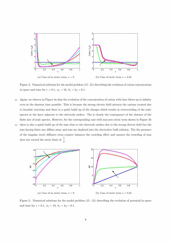
0 0.2 0.4 0.6 0.8 10
1
2
3
4
5
6
x
Cat
ion,
C2(t
)
t
(a) Case of no steric term, ν = 0
0 0.2 0.4 0.6 0.8 10
1
2
3
4
5
6
x
Cat
ion,
C2(t
)
t
(b) Case of steric term ν = 0.25
Figure 4: Numerical solutions for the model problem (15 - 21) describing the evolution of cation concentration
in space and time for ϵ = 0.1, ϕe = 10, k1 = k2 = 0.1.
Again, we observe in Figure 4a that the evolution of the concentration of cation with time blows up to infinity155
even at the shortest time possible. This is because the strong electric field attracts the cations created due
to faradaic reactions and there is a quick build up of the charges which results in overcrowding of the ionic
species at the layer adjacent to the electrode surface. The is clearly the consequence of the absence of the
finite size of ionic species. However, for the corresponding case with non-zero steric term shown in Figure 4b
there is also a quick build up of the ions close to the electrode surface due to the strong electric field but the160
ions having finite size diffuse away and ions are depleted into the electrolyte bulk solution. The the presence
of the singular steric diffusive term counter balances the crowding effect and ensures the crowding of ions
does not exceed the steric limit of,1
ν.
0 0.2 0.4 0.6 0.8 1−40
−30
−20
−10
0
10
x
φ(t)
t
(a) Case of no steric term, ν = 0
0 0.2 0.4 0.6 0.8 10
5
10
15
20
x
φ(t)
t
(b) Case of steric term ν = 0.25
Figure 5: Numerical solutions for the model problem (15 - 21) describing the evolution of potential in space
and time for ϵ = 0.1, ϕe = 10, k1 = k2 = 0.1.
9

5. Conclusion
We have simulated a dynamic mechanistic model which describe the transient response of the electric double165
layer in a microelectrochemical system. The model account for the finite size ion properties and incorporate
charge transfer kinetics. The model also allows for simulating arbitrary electrolyte in the system. At the
electrode/electrolyte interface, the reaction kinetics depends on the drop in potential within the compact layer
of the electric double layer. The numerical results show dynamical changes of the the ionic concentration and
the local ionic potentials. The present study could open up a promising perspective for the design of highly170
sensitive microchemical system. In order to achieve this, higher dimension system is necessary.
6. Acknowledgement
We acknowledge financial support from the Villum Kann Rasmussen centre of Excellence: Nano Mechanical
Sensors and Actuators, fundamentals and new directions (NAMEC).
References175
[1] J. Bates, N. Dudney, G. Gruzalski, R. Zuhr, A. Choudhury, C. Luck, J. Robertson, Fabrication and
characterization of amorphous lithium electrolyte thin films and rechargeable thin-film batteries, Journal
of Power Sources 43 (13) (1993) 103 – 110. doi:http://dx.doi.org/10.1016/0378-7753(93)80106-Y.
[2] D. Danilov, P. Notten, Mathematical modelling of ionic transport in the elec-
trolyte of li-ion batteries, Electrochimica Acta 53 (17) (2008) 5569 – 5578.180
doi:http://dx.doi.org/10.1016/j.electacta.2008.02.086.
[3] R. A. Huggins, Advanced Batteries : Materials Science Aspects, Springer, New York, 2008.
[4] I. Quinzeni, S. Ferrari, E. Quartarone, D. Capsoni, M. Caputo, A. Goldoni, P. Mustarelli, M. Bini,
Fabrication and electrochemical characterization of amorphous lithium iron silicate thin films as
positive electrodes for lithium batteries, Journal of Power Sources 266 (0) (2014) 179 – 185.185
doi:http://dx.doi.org/10.1016/j.jpowsour.2014.05.012.
[5] F. Nadal, F. Argoul, P. Hanusse, B. Pouligny, A. Ajdari, Electrically induced interactions be-
tween colloidal particles in the vicinity of a conducting plane, Phys. Rev. E 65 (2002) 061409.
doi:10.1103/PhysRevE.65.061409.
[6] R. J. Hunter, Foundations of colloid science, 2nd Edition, Oxford University Press, 2001.190
[7] M. Z. Bazant, M. S. Kilic, B. D. Storey, A. Ajdari, Towards an understanding of induced-charge elec-
trokinetics at large applied voltages in concentrated solutions, Advances in Colloid and Interface Science
152 (12) (2009) 48 – 88. doi:http://dx.doi.org/10.1016/j.cis.2009.10.001.
10

[8] V. Barcilon, D. Chen, R. Eisenberg, Ion flow through narrow membrane channels: Part ii, SIAM J.
Appl. Math. 52 (5) (1992) 1405–1425. doi:10.1137/0152081.195
[9] J. C. Weaver, Electroporation: A general phenomenon for manipulating cells and tissues, Journal of
Cellular Biochemistry 51 (4) (1993) 426–435. doi:10.1002/jcb.2400510407.
[10] M. Bazant, K. Chu, B. Bayly, Current-voltage relations for electrochemical thin films, SIAM Journal on
Applied Mathematics 65 (5) (2005) 1463–1484. doi:10.1137/040609938.
[11] H. Lu, M. A. Schmidt, K. F. Jensen, A microfluidic electroporation device for cell lysis, Lab Chip 5200
(2005) 23–29. doi:10.1039/B406205A.
URL http://dx.doi.org/10.1039/B406205A
[12] T. M. Squires, M. Z. Bazant, Induced-charge electro-osmosis, Journal of Fluid Mechanics 509 (2004)
217–252. doi:10.1017/S0022112004009309.
[13] L. H. Olesen, H. Bruus, A. Ajdari, Ac electrokinetic micropumps: The effect of geometrical confine-205
ment, faradaic current injection, and nonlinear surface capacitance, Phys. Rev. E 73 (2006) 056313.
doi:10.1103/PhysRevE.73.056313.
[14] A. J. Pascall, T. M. Squires, Induced charge electro-osmosis over controllably contaminated electrodes,
Phys. Rev. Lett. 104 (2010) 088301. doi:10.1103/PhysRevLett.104.088301.
URL http://link.aps.org/doi/10.1103/PhysRevLett.104.088301210
[15] A. Ramos, Electrokinetics and Electrohydrodynamics In Microsystems, Dordrecht: Springer, 2011.
[16] I. Sprague, P. Dutta, Depth averaged analytic solution for a laminar flow fuel cell with electric double
layer effects, SIAM Journal on Applied Mathematics 72 (4) (2012) 1149–1168. doi:10.1137/110843113.
[17] I. B. Sprague, P. Dutta, Improved kinetics from ion advection through overlapping elec-
tric double layers in nano-porous electrodes, Electrochimica Acta 91 (0) (2013) 20 – 29.215
doi:10.1016/j.electacta.2012.12.015.
[18] N. Walther, Zur kinetik der in losung befindlichen korper. erste abhandlung. theorie der diffusion, Z.
phys.Chem. 9 (2) (1888) 613637.
[19] M. Planck, Ueber die erregung von electricitat und warme in electrolyten, Ann. Phys. Chem 275 (2)
(1890) 161–186. doi:10.1002/andp.18902750202.220
[20] K. G. Hans-Jrgen Butt, M. Kappl., Physics and Chemistry of Interfaces, WILEY-VCH Verlag, Weinheim,
2003.
[21] P. Geoffrey, Electrochemical Engineering Principles, Prentice Hall, New Jersey, 2003.
11

[22] O. Stern, Zur theorie der elektrolytischen doppelschicht, Z Electrochem. 30 (21-22) (1924) 508–516.
doi:10.1002/bbpc.192400182.225
[23] D. C. Grahame, The electrical double layer and the theory of electrocapillarity., Chemical Reviews 41 (3)
(1947) 441–501. doi:10.1021/cr60130a002.
[24] M. Van Soestbergen, Frumkin-butler-volmer theory and mass transfer in electrochemical cells, Russian
Journal of Electrochemistry 48 (6) (2012) 570–579. doi:10.1134/S1023193512060110.
[25] A. Frumkin, Hydrogen overvoltage and structure of the double layer, Z. Phys. Chem. 164 (1-2) (1933)230
121–133.
[26] K. Chu, M. Bazant, Electrochemical thin films at and above the classical limiting current, SIAM J.
Appl. Math. 65 (5) (2005) 1485–1505. doi:10.1137/040609926.
[27] A. Bonnefont, F. Argoul, M. Z. Bazant, Analysis of diffuse-layer effects on time-dependent interfacial
kinetics, Electroana. Chem 500 (12) (2001) 52 – 61. doi:10.1016/S0022-0728(00)00470-8.235
[28] M. van Soestbergen, P. M. Biesheuvel, M. Z. Bazant, Diffuse-charge effects on the transient response of
electrochemical cells, Phys. Rev. E 81 (2010) 021503. doi:10.1103/PhysRevE.81.021503.
[29] M. S. Kilic, M. Z. Bazant, A. Ajdari, Steric effects in the dynamics of electrolytes at large
applied voltages. II. Modified Poisson-Nernst-Planck equations, Phys. Rev. E 75 (2007) 021503.
doi:10.1103/PhysRevE.75.021503.240
[30] L. Højgaard Olesen, M. Z. Bazant, H. Bruus, Strongly nonlinear dynamics of electrolytes in large ac
voltages, Phys. Rev. E 82 (2010) 011501. doi:10.1103/PhysRevE.82.011501.
[31] M. Z. Bazant, M. S. Kilic, B. D. Storey, A. Ajdari, Towards an understanding of induced-charge elec-
trokinetics at large applied voltages in concentrated solutions, Advances in Colloid and Interface Science
152 (12) (2009) 48 – 88. doi:http://dx.doi.org/10.1016/j.cis.2009.10.001.245
[32] M. A. Efendiev, Evolution Equations Arising in the Modelling of Life Sciences, Birkhaser, Basel, 2013.
[33] W. B. J. Zimmerman, Multiphysics Modelling with Finite Elements Methods, World Scientific Publishing
Co. Singapore, 2006.
[34] Comsol R⃝multiphysics finite element analysis software.
[35] M. S. Kilic, M. Z. Bazant, A. Ajdari, Steric effects in the dynamics of electrolytes at large applied250
voltages. I. Double-layer charging, Phys. Rev. E 75 (2007) 021502. doi:10.1103/PhysRevE.75.021502.
[36] M. van Soestbergen, Ionic currents exceeding the diffusion limitation in planar nano-cavities, Electro-
chemistry Communications 20 (0) (2012) 105 – 108. doi:10.1016/j.elecom.2012.03.034.
12

[37] I. Borukhov, D. Andelman, H. Orland, Steric effects in electrolytes: A modified poisson-boltzmann
equation, Phys. Rev. Lett. 79 (1997) 435–438. doi:10.1103/PhysRevLett.79.435.255
[38] M. Z. Bazant, K. Thornton, A. Ajdari, Diffuse-charge dynamics in electrochemical systems, Phys. Rev.
E 70 (2004) 021506. doi:10.1103/PhysRevE.70.021506.
[39] P. Biesheuvel, M. van Soestbergen, M. Bazant, Imposed currents in galvanic cells, Electrochimica Acta
54 (21) (2009) 4857 – 4871. doi:http://dx.doi.org/10.1016/j.electacta.2009.03.073.
[40] A. J. Bard, L. R. Faulkner, Electrochemical Methods: Fundamentals and Applications, 2nd Edition,260
John Wiley & Sons, 2001.
[41] M. H. Holmes, Introduction to Perturbation Methods, Springer, New York, 2013.
[42] J. Newman, The polarized diffuse double layer, Trans. Faraday Soc. 61 (1965) 2229–2237.
13

Chapter 7
Conclusion and Outlook
There is a great collection of literature on the theory and numerics of electro-chemical systems in general. Many complex phenomena like the charge transfer,diffusion, reaction dynamics have been researched based on these studies. Thisthesis focuses on the simulations of the microelectrochemical systems which de-viates slightly from the standard approach.
In order to distinguish the macro and micro systems, we start by consideringthe Nernst-Planck equations which is a system of advection-diffusion-reactionpartial differential equations solved with the Poisson equation. The assumptionof electroneutrality reduces the Poisson equation to the Laplace equation andhence the right hand side of the differential equation for the potential fieldequals zero. Furthermore, the flux condition relates the current density to thecharge transfer across the electrolyte/electrode interface through the Butler-Volmer relation. The overpotential term in the Butler-Volmer relation definesthe potential drop between the electrode and the bulk electrolyte. This term iscrucial when modeling microelectrochemical systems where the dynamics of theelectrode/electrolyte interface cannot be ignored. In the thesis, we incorporatedthe electric double layer model which divides the electrode/electrolyte into theStern and the diffuse layers. The Stern layer is modelled by a Robin typeboundary condition which also affects the charge transfer and thus utilize amodified Butler-Volmer equation.

96 Conclusion and Outlook
In modeling electrochemical systems, ions are normally treated as point charges,but because of huge electric fields in the double layer ionic species can becomecrowded in this region and the ionic concentration tends to infinity. The intro-duction of finite size properties of ions overcomes this effect and thus a moreappropriate model for the electrochemical systems especially the miniaturizedsize.
The results have been reported in two parts. The first part presents the mech-anism of the electrochemical systems through cyclic voltammetry in a fluidicsystem in which electrolyte solution was pumped in and out of the system. Theresults through computations show the influence of the convection and the scanrate in an electrochemical system which can affect the system dynamics. Theinformation gathered from such computations could be very useful in the ex-perimental design as well as very useful in providing insight when designingelectrochemical systems of high sensitivity.
Another interesting contribution from the first part is that the placement ofelectrodes is critical when performing cyclic voltammetry experiments underflow. The main difference between the centered placed electrode and the bot-tom placed electrode is the delay in the conversion of the fresh ionic speciesbrought to the electrode surface for the bottom placed electrode when the scanrate is slow. In the centered placed electrode the influence is more apparentsince the variation can be seen in the current response recorded during cyclicvoltammetry. We were able to identify the characteristics of the hydrodynamiceffect on the the dynamics of the current response to the applied voltage in cyclicvoltammetry measurements. Qualitative and often also quantitative agreementare found between experimental and the numerical predictions for cyclic voltam-metry measurements.
The second part of the thesis provides simulations for the dynamic mechanisticmodel which described the transient response of the electric double layer in a mi-croelectrochemical system. The model accounts for the finite size ion propertiesand incorporates charge transfer kinetics. The model also allows for simulat-ing arbitrary electrolytes in the system. At the electrode/electrolyte interface,the reaction kinetics depend on the drop in potential within the compact layerof the electric double layer. The numerical results show dynamical changes ofthe ionic concentration and the local ionic potentials. In the example we simu-lated a system in which the electrolyte is non-binary and the reaction kineticscomplicates the computation.
Based on the motivation from the numerical computations, we solve for thesteady state solution for the mass transport equations that contains the stericproperties of the ionic charges. The result suggests that the analytic solutionto the problem consists of traveling wave solutions obtained from non-linear

97
diffusion equations. However, further investigation is needed for this result.
As a final remark, there are several challenges and extensions that could be madein the present study. Reactions like coating, functionalization of the electrodescould be modeled and simulated in cyclic voltammetry. Furthermore, for thedesign and optimization of the electrochemical system, the investigation of thefull 3D problem may be needed. A further research area is to simulate cyclicvoltammetry of the microelectrochemical system with the steric properties andproper electric double layer boundary conditions. Finally, theoretical analysis ofmicroelectrochemical systems, for example through asymptotic expansion couldalso be pursued. This is still ongoing.

98 Conclusion and Outlook

Appendix A
Appendix
The purpose of this section is to present the non-dimensionalization of the equa-tions we solved in Paper III and also in chapter 3 where we present the summaryof the result. We state all the equations involved for modeling the microelectro-chemical system and non-dimensionalize them appropriately.
A.1 Dimensional analysis for the model equation
In a microelectrochemical system, the dynamics of ionic species satisfies themass transport equations
∂Ci∂t
=∂
∂x
(Di∂Ci∂x
+DiF
RTziCi
∂φ
∂x+
a3DiCi1−∑i Cia
3
∂(∑i Ci)
∂x
). (A.1)
The first term on the right hand side of equation (A.1) corresponds to a diffusionterm due to the ionic concentration gradient within the electrolyte solution.The second term is the electromigration driven by the gradient of the electricpotential while the last term represents the nonlinear diffusion term that can

100 Appendix
lead to the saturation of ion concentrations at the surface of the electrode. Here,we do not include the term due to convection.
In order to couple the local potential term to equation (A.1), we solve thePoisson equation
∂
∂x(−εb
∂φ
∂x) = F
∑
i
ziCi, (A.2)
A.1.1 Boundary Conditions
In what follows, we shall consider a two electrode system that is separated bya length L and sandwiches an electrolyte solution. We consider an electrolytesolution that is arbitrary and allow the valence of ionic species to be of oppositesigns. Across the electrode/electrolyte interface Faradaic reactions are involvedand hence the ionic flux boundary conditions for the charge transfer is given by
Ji = Di∂Ci∂x
+DiF
RTziCi
∂φ
∂x+
a3DiCi1−∑i Cia
3
∂(∑i Ci)
∂x. (A.3)
Here, Ji is the current density within the electrochemical system. The currentdue to motion of all charges in an electrochemical system is the Faradaic currentwritten as the sum of all local currents, that is,
JF = F∑
i
ziJi. (A.4)
At the electrode, the Faradaic current JF which contributes to surface reactionand is related to local concentrations and potential through the generalizedFrumkin-Butler–Volmer kinetic relation [27], takes the form
JF = kRC1 exp(−αz1FRT4φs)− kOC2 exp((1− α)
z2F
RT4φs), (A.5)
where ki are the rate constants, α is the transfer coefficient, R is the gas constantand T is the temperature. The choice C1 and C2 will become immediately clear
in the next section. Furthermore, 4φs = φ
∣∣∣∣rp
∓ φe is the potential drop across
the compact Stern layer. The variables involved are defined below.
Following Bazant et al [23] we prescribed Robin type boundary conditions forthe electric potential as follows
φ
∣∣∣∣rp
= ±φe ∓ λS∂φ
∂n
∣∣∣∣rp
, (A.6)

A.2 Dimensionless equations 101
where λS is the effective width of the compact layer of the electric double layer,φ|rp is the electric potential at the reaction plane, φ|e is the applied potentialon the electrode and n is the normal pointing towards the electrolyte solution.We have adopted a sign convection that current flowing towards the cathode isnegative.
A.2 Dimensionless equations
We introduce the following scaling parameters
x∗ =x
L, C∗
i =CiCref
, φ∗ =Fφ
RT, (A.7)
ki =Di
D, t∗ =
tD
L2, ν = a3Cref , (A.8)
in order to nondimensionalize the equations (A.1 - A.6). Here, Cref , R andD are the reference concentration, the gas constant and a constant diffusivityrespectively. We insert the scaling parameters into A.1 and obtain
DCrefL2
∂C∗i
∂t∗=
∂
L∂x∗
(kiDCref
L
∂C∗i
∂x∗+sign(zi)zikiDCrefC
∗i
L
∂φ∗
∂x∗(A.9)
+a3kiDCrefC
∗i
L(1− a3Cref∑i C
∗i )
∂(∑i CrefC
∗i )
∂x∗
). (A.10)
When both sides of equation (A.10) are multiplied byL2
DCrefwe arrive at
∂C∗i
∂t∗= ki
∂
∂x∗
(∂C∗
i
∂x∗+ sign(zi)ziC
∗i
∂φ∗
∂x∗+
νC∗i
1− ν(∑i C
∗i )
∂(∑i C
∗i )
∂x∗
). (A.11)
Since we chose an electrolyte solution that is arbitrary and allow the charges ofionic species to be of opposite signs such that when the ∗ is dropped we canwrite the following
∂C1
∂t= k1
∂
∂x
(∂C1
∂x− z1C1
∂φ
∂x+
νC1
1− ν(C1 + C2)
∂(C1 + C2)
∂x
), (A.12)
∂C2
∂t= k2
∂
∂x
(∂C2
∂x+ z2C2
∂φ
∂x+
νC2
1− ν(C1 + C2)
∂(C1 + C2)
∂x
). (A.13)

102 Appendix
Now recall the Poisson problem (A.2),
∂
∂x(−ε∂φ
∂x) = F
∑
i
ziCi, (A.14)
we substitute the dimensionless parameter defined in equation (A.7) to get
1
L
∂
∂x∗(− εL
∂
∂x∗
(RTφ∗
F
)) = FCref
∑
i
ziC∗i , (A.15)
and when we re-arrange and drop the ∗ we obtain
−(λDL
)2∂2φ
∂x2=∑
i
ziCi, (A.16)
where λD =
√εRT
F 2Crefis the Debye length signifying the electrolyte region
where charge neutrality fails to be evenly approximated. If we chose the Debyelength λD as the natural scale for charge screening then one can define another
dimensionless parameter, ε =λDL
such that
−ε2 ∂2φ
∂x2=∑
i
ziCi, is satisfied. (A.17)
The parameter ε is the governing small parameter for the matched asymptoticexpansion to be considered in the later section.
A.2.1 Dimensionless Ion flux B.C
Recall the ionic flux boundary conditions,
Ji = Di∂Ci∂x
+DiF
RTziCi
∂φ
∂x+
a3DiCi1−∑± Cia
3
∂(∑i Ci)
∂x. (A.18)
By inserting the scaling parameters from equation (A.7) one gets
Ji =kiDCref
L
(∂C∗
i
∂x+ sign(zi)ziC
∗i
∂φ∗
∂x+
νC∗i
1− ν∑i C∗i
∂(∑i C
∗i )
∂x
), (A.19)

A.2 Dimensionless equations 103
which results in the dimensionless fluxes
ji = ki
(∂C∗
i
∂x+ sign(zi)ziC
∗i
∂φ∗
∂x+
νC∗i
1− ν∑i C∗i
∂(∑i C
∗i )
∂x
), (A.20)
defined by
ji =L
DCrefJi. (A.21)
Now Faradaic current is defined as the sum of individual ionic currents writtenas
JF = F∑
i
ziJi. (A.22)
When we substitute equation (A.21) into (A.22) we obtain
JF =DFCref
L
∑
i
ziji, (A.23)
which in turn gives the dimensionless Faradaic current
jF =∑
i
ziji (A.24)
that scaled the dimensional Faradaic current such that jF =L
DFCrefJF . Now
recall the surface kinetics defined by equation (A.3),
JF = kRC1 exp(−αz1FRT4φs)− kOC2 exp((1− α)
z2F
RT4φs), (A.25)
and substitute dimensional Faradaic current equation into equation (A.25) sothat
DFCrefL
jF = kRC1 exp(−αz1FRT4φs)− kOC2 exp((1− α)
z2F
RT4φs) (A.26)
and when both sides are multiplied byL
DFCrefwe obtain
jF =LkRDF
C1
Crefexp(−αz1F
RT4φs)−
LkODFCref
C2
Crefexp((1−α)
z2F
RT4φs). (A.27)

104 Appendix
Using the scaling parameters defined in (A.7) we formally obtain the non-dimensional surface reaction kinetics equation
jF = k∗RC∗1 exp(−αz14φ∗s)− k∗OC∗
2 exp((1− α)z24φ∗s), (A.28)
where k∗R =L
DFkR ; k∗O =
L
DFkO are the dimensionless rate constants.
A.2.2 Dimensionless Poisson B.C
Now consider the boundary condition for the Poisson problem,
φ
∣∣∣∣rp
= ±φe ∓ λS∂φ
∂x
∣∣∣∣rp
. (A.29)
Again, we insert the scaling parameters in (A.7) such that(RT
F
)φ∗∣∣∣∣rp
= ±φe ∓λSL
(RT
F
)∂φ∗
∂x∗
∣∣∣∣rp
. (A.30)
We multiply the right hand side of (A.30) byλDλD
and re-arrange as follows,
φ∗∣∣∣∣rp
= ±(F
RT
)φe ∓
λSλD
λDL
∂φ∗
∂x∗
∣∣∣∣rp
. (A.31)
Finally, we define another dimensionless parameter δ =λSλD
the ratio of the
effective width of the compact and diffuse parts of the electric double layer.
φ∗∣∣∣∣rp
= ±φ∗|e ∓ δε∂φ∗
∂x∗
∣∣∣∣rp
. (A.32)
A.3 The model and the boundary conditions
We want to solve the following model
∂C1
∂t= k1
∂
∂x
(∂C1
∂x− z1C1
∂φ
∂x+
νC1
1− ν(C1 + C2)
∂(C1 + C2)
∂x
), (A.33)

A.3 The model and the boundary conditions 105
∂C2
∂t= k2
∂
∂x
(∂C2
∂x+ z2C2
∂φ
∂x+
νC2
1− ν(C1 + C2)
∂(C1 + C2)
∂x
), (A.34)
−ε2 ∂2φ
∂x2=∑
i
ziCi, (A.35)
for a microelectrochemical system satisfying the following boundary conditions
jF = kRC1 exp(−αz14φs)− kOC2 exp((1− α)z24φs) (A.36)
the nondimensional Faradaic current which can be accessed through equations(A.20) and (A.24), and
φ
∣∣∣∣rp
= ±φ|e ∓ δε∂φ
∂x
∣∣∣∣rp
, (A.37)
with parameters δ, ε are defined in previous sections.

106 Appendix
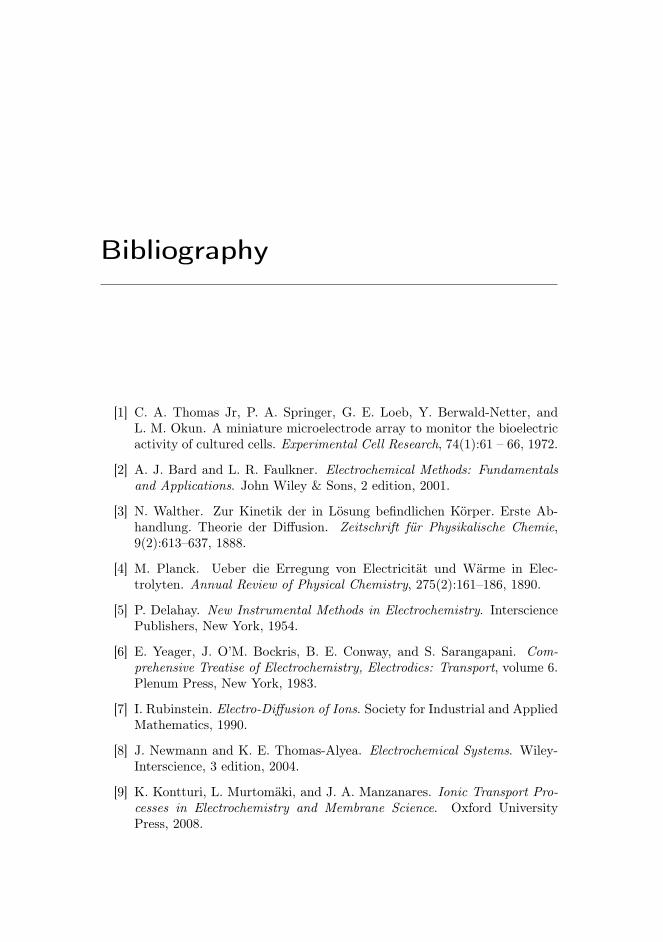
Bibliography
[1] C. A. Thomas Jr, P. A. Springer, G. E. Loeb, Y. Berwald-Netter, andL. M. Okun. A miniature microelectrode array to monitor the bioelectricactivity of cultured cells. Experimental Cell Research, 74(1):61 – 66, 1972.
[2] A. J. Bard and L. R. Faulkner. Electrochemical Methods: Fundamentalsand Applications. John Wiley & Sons, 2 edition, 2001.
[3] N. Walther. Zur Kinetik der in Lösung befindlichen Körper. Erste Ab-handlung. Theorie der Diffusion. Zeitschrift für Physikalische Chemie,9(2):613–637, 1888.
[4] M. Planck. Ueber die Erregung von Electricität und Wärme in Elec-trolyten. Annual Review of Physical Chemistry, 275(2):161–186, 1890.
[5] P. Delahay. New Instrumental Methods in Electrochemistry. IntersciencePublishers, New York, 1954.
[6] E. Yeager, J. O’M. Bockris, B. E. Conway, and S. Sarangapani. Com-prehensive Treatise of Electrochemistry, Electrodics: Transport, volume 6.Plenum Press, New York, 1983.
[7] I. Rubinstein. Electro-Diffusion of Ions. Society for Industrial and AppliedMathematics, 1990.
[8] J. Newmann and K. E. Thomas-Alyea. Electrochemical Systems. Wiley-Interscience, 3 edition, 2004.
[9] K. Kontturi, L. Murtomäki, and J. A. Manzanares. Ionic Transport Pro-cesses in Electrochemistry and Membrane Science. Oxford UniversityPress, 2008.

108 BIBLIOGRAPHY
[10] R. G. Compton and C. E. Banks. Understanding Voltammetry. WorldScientifice, 2 edition, 2011.
[11] J. Leddy, V. Birss, and P. Vanysek. Historical Perspectives on the Evolu-tion of Electrochemical Tools. The Electrochemical Society, NJ, 2004.
[12] A. J. Bard and R. W. Murray. Electrochemistry. PNAS, 109(12):11484–11486, 2012.
[13] V. M. Volgin and A. D. Davydov. Mass-transfer problems in the elec-trochemical systems. Russian Journal of Electrochemistry, 48(6):565–569,2012.
[14] G. A. Prentice and C. W. Tobias. A survey of numerical methods andsolutions for current distribution problems. Journal of The ElectrochemicalSociety, 129(1):72–78, 1982.
[15] M. Schlesinger. Mathematical Modeling in Electrochemistry, in ModernAspects of Electrochemistry, volume 43. Springer, New York, 2008.
[16] R. N. Adams. In vivo electrochemical recording — a new neurophysiolog-ical approach. Trends in Neurosciences, 1(2):160 – 163, 1978.
[17] H. Y. Cheng, J. Schenk, R. Huff, and R. N. Adams. In vivo electrochem-istry: behavior of micro electrodes in brain tissue. Journal of Electro-analytical Chemistry and Interfacial Electrochemistry, 100(1–2):23 – 31,1979.
[18] R. M. Wightman A. G. Ewing, M. A. Dayton. Pulse voltammetry withmicrovoltammetric electrodes. Analytical Chemistry, 12(53):1842–1847,1981.
[19] H. J. Butt, K. Graf, and M. Kappl. Physics and Chemistry of Interfaces.WILEY-VCH Verlag, Weinheim, 2003.
[20] G. Prentice. Electrochemical Engineering Principles. Prentice Hall, NewJersey, 2003.
[21] O. Stern. Zur theorie der elektrolytischen doppelschicht. Zeitschrift fürElektrochemie, 30(21-22):508–516, 1924.
[22] D. C. Grahame. The electrical double layer and the theory of electrocap-illarity. Chemical Reviews, 41(3):441–501, 1947.
[23] M. Bazant, K. Chu, and B. Bayly. Current-voltage relations for electro-chemical thin films. SIAM Journal on Applied Mathematics, 65(5):1463–1484, 2005.

BIBLIOGRAPHY 109
[24] K. Chu and M. Z Bazant. Electrochemical thin films at and above the clas-sical limiting current. SIAM Journal of Applied Mathematics, 65(5):1485–1505, 2005.
[25] A. Bonnefont, F. Argoul, and M. Z. Bazant. Asymptotic analysis ofdiffuse-layer effects on time-dependent interfacial kinetics. Electroana-lytical Chemistry, 500(1–2):52 – 61, 2001.
[26] M. van Soestbergen, P. M. Biesheuvel, and M. Z. Bazant. Diffuse-chargeeffects on the transient response of electrochemical cells. Physical ReviewE, 81:021503, Feb 2010.
[27] M. van Soestbergen. Frumkin-butler-volmer theory and mass transfer inelectrochemical cells. Russian Journal of Electrochemistry, 48(6):570–579,2012.
[28] M. Z. Bazant, M. S. Kilic, B. D. Storey, and A. Ajdari. Towards anunderstanding of induced-charge electrokinetics at large applied voltagesin concentrated solutions. Advances in Colloid and Interface Science,152(1–2):48 – 88, 2009.
[29] M. S. Kilic and M. Z. Bazant. Steric effects in the dynamics of electrolytesat large applied voltages. II. Modified Poisson-Nernst-Planck equations.Physical Review E, 75:1 – 11, 2007.
[30] O. L. Højgaard, M. Z. Bazant, and H. Bruus. Strongly nonlinear dynamicsof electrolytes in large ac voltages. Physical Review E, 82:011501, Jul 2010.
[31] T. Erdy-Gruz and M. Volmer. Zeitschrift für Physikalische Chemie,203:150–157, 1931.
[32] J. A. V. Butler. Transactions of the Faraday Society, 28:379, 1931.
[33] G. K. Batchelor. An Introduction to fluids dynamics. Cambridge Univer-sity Press, 1967.
[34] J. Fuhrmann, A. Linke, and H. Langmach. A numerical method for massconservative coupling between fluid flow and solute transport. AppliedNumerical Mathematics, 61:530–553, 2011.
[35] M. S. Kilic, M. Z. Bazant, and A. Ajdari. Steric effects in the dynamics ofelectrolytes at large applied voltages. I. Double-layer charging. PhysicalReview E, 75:021502, Feb 2007.
[36] Z. Adamczyk and P. Warszyński. Role of electrostatic interactions inparticle adsorption. Advances in Colloid and Interface Science, 63(0):41– 149, 1996.

110 BIBLIOGRAPHY
[37] Comsol multiphysics finite element analysis software R©.http://www.comsol.com.
[38] V. Thomee. Galerkin Finite Element Methods for Parabolic Problems.Springer, New York: Springer Series in Computational Mathematics, Vol.25, 2006.
[39] S. Brenner and R. Scott. The Mathematical Theory of Finite ElementMethods. Springer, New York: Texts in Applied Mathematics, Vol. 15,2008.
[40] W. B. J. Zimmerman. Multiphysics Modelling with Finite Elements Meth-ods. World Scientific Publishing Co. Singapore, 2006.
[41] K. Dmitri and H. Jari. Finite Element Methods for Computational FluidDynamics: A Practical Guide. SIAM, 2014.
[42] A. C. Fisher and R. G. Compton. A general computational approachto linear sweep voltammetry at channel electrodes. Journal of AppliedElectrochemistry, 22:38–42, 1992.
[43] R. G. Compton, A. C. Fisher, R. G. Wellington, P. J. Dobson, and P. A.Leigh. Hydrodynamic voltammetry with microelectrodes: channel mi-croband electrodes; theory and experiment. Journal of Physical Chem-istry, 97(40):10410–10415, 1993.
[44] N. V. Rees, R. A. W. Dryfe, J. A. Cooper, B. A. Coles, R. G. Comp-ton, S. G. Davies, and T. D. McCarthy. Voltammetry under High MassTransport Conditions. A High Speed Channel Electrode for the Studyof Ultrafast Kinetics. Journal of Physical Chemistry, 99(18):7096–7101,1995.
[45] J. A. Alden, M. A. Feldman, E. Hill, F. Prieto, M. Oyama, B. A. Coles,R. G. Compton, P. J. Dobson, and P. A. Leigh. Channel microband elec-trode arrays for mechanistic electrochemistry. Two-dimensional voltam-metry: transport-limited currents. Analytical Chemistry, 70(9):1707–20,1998.
[46] N. V. Rees, O. V. Klymenko, E. Maisonhaute, B. A. Coles, and R. G.Compton. The application of fast scan cyclic voltammetry to the highspeed channel electrode. Journal of Electroanalytical Chemistry, 542:23–32, 2003.
[47] S. M. Matthews, G. Q. Du, and A. C. Fisher. Microfluidic voltamme-try: simulation of the chronoamperometric response of microband elec-trodes sited within microreactors. Journal of Solid State Electrochemistry,10(10):817–825, 2006.
BIBLIOGRAPHY 111
[48] F. G. E. Jones and R. A. W. Dryfe. Hydrodynamic voltammetry atthe interface between immiscible electrolyte solutions: Numerical simula-tion of the voltarnmetric response. Journal of electroanalytical chemistry,615(1):25–33, 2008.
[49] M. van Soestbergen. Ionic currents exceeding the diffusion limitation inplanar nano-cavities. Electrochemistry Communications, 20(0):105 – 108,2012.
[50] M. van Soestbergen, P. M. Biesheuvel, and M. Z. Bazant. Diffuse-chargeeffects on the transient response of electrochemical cells. Physical ReviewE, 81:021503, Feb 2010.
[51] M. A. Urtenov, E. V. Kirillova, N. M. Seidova, and V. V. Nikonenko.Decoupling of the nernst-planck and poisson equations. application to amembrane system at overlimiting currents. The Journal of Physical Chem-istry B, 111(51):14208–14222, 2007.
[52] S. Chevion, M. Hofmann, R. Ziegler, M. Chevion, and P. P. Nawroth.The antioxidant properties of thioctic acid: characterization by cyclicvoltammetry. International Journal of Biochemistry and Molecular Bi-ology, 41(2):317–327, 1997.
[53] S. Chevion, M. A. Roberts, and M. Chevion. The use of cyclic voltam-metry for the evaluation of antioxidant capacity. Free Radical Biology &Medicine, 28(6):860–870, 2000.
[54] D. Grieshaber, R. MacKenzie, J. Voros, and E. Reimhult. Electrochemicalbiosensors - sensor principles and architectures. Sensors, 8(3):1400–1458,2008.
[55] N. Cruys-Bagger, S. F. Badino, R. Tokin, M. Gontsarik, S. Fathalinejad,K. Jensen, M. D. Toscano, T. H. Sørensen, K. Borch, H. Tatsumi, P. Väl-jamäe, and P. Westha. A pyranose dehydrogenase-based biosensor forkinetic analysis of enzymatic hydrolysis of cellulose by cellulases. Enzymeand Microbial Technology, 58:68 – 74, 2014.
[56] L. M. Fischer, C. Pedersen, K. Elkjær, N. N. Noeth, S. Dohn, A. Boisen,and M. Tenje. Development of a microfabricated electrochemical-cantilever hybrid platform. Sensors and Actuators B: Chemical,157(1):321–327, 2011.
[57] R. S. Nicholson and I. Shain. Theory of stationary electrode polarography- scan and cyclic methods applied to reversible, irreversible, and kineticsystems. Analytical Chemistry, 36(4):707–723, 1964.

112 BIBLIOGRAPHY
[58] G. Jidong and L. Ernő. Cyclic voltammetry at shallow recessed microdiscelectrode: Theoretical and experimental study. Journal of Electroanalyti-cal Chemistry, 629(1-2):180–184, 2009.
[59] C. Meng-Hsuan. A numerical method for analysis of tertiary current dis-tribution in unsteady natural convection multi-ion electrodeposition. Elec-trochimica Acta, 45(24):3959–3972, 2000.
[60] J. V. Macpherson, N. Simjee, and P. R. Unwin. Hydrodynamic ultrami-croelectrodes: kinetic and analytical applications. Electrochimica Acta,47(1-2):29–45, 2001.
[61] A. J. Wain, R. G. Compton, R. Le Roux, S. Matthews, and A. C. Fisher.Microfluidic channel flow cell for simultaneous cryoelectrochemical elec-tron spin resonance. Analytical Chemistry, 79(5):1865–73, 2007.
[62] C. T. J. Low, E. P. L. Roberts, and F. C. Walsh. Numerical simulation ofthe current, potential and concentration distributions along the cathodeof a rotating cylinder hull cell. Electrochimica Acta, 52(11):3831–3840,2007.
[63] L. Uziel. Modern Aspects of Electrochemistry No. 44, volume 44 ofModernAspects of Electrochemistry. Springer New York, New York, NY, 2009.
[64] H. R. Corti, D. L. Goldfurb, M. S. Ortiz, and J. F. Magallanes. Tubularband microelectrode. I. Design and electrochemical behavior. Electroanal-ysis, 7(6):569–573, 1995.
[65] M. Takahashi, S. Tobishima, K. Takei, and Y. Sakurai. Reaction behaviorof LiFePO4 as a cathode material for rechargeable lithium batteries. SolidState Ionics, 148:283–289, 2002.
[66] W. J. Aixill, A. C. Fisher, and Q. Fulian. Hydrodynamic microelectrodes.the microstrip electrode: Theory and experiment. Journal of PhysicalChemistry, 3654(100):14067–14073, 1996.
[67] K. S. Hwang, S. M. Lee, S. K. Kim, J. H. Lee, and T. S. Kim. Micro-and nanocantilever devices and systems for biomolecule detection. AnnualReview Analytical Chemistry, 2:77–98, 2009.
[68] N. V. Rees, J. A. Alden, R. A. W. Dryfe, B. A. Coles, and R. G. Compton.Voltammetry under high mass transport conditions. The high speed chan-nel electrode and heterogeneous kinetics. Journal of Physical Chemistry,pages 14813–14818, 1995.
[69] X. Quan, L. M. Fischer, A. Boisen, and M. Tenje. Development ofnanoporous gold electrodes for electrochemical applications. Microelec-tronic Engineering, 88(8):2379–2382, 2011.

BIBLIOGRAPHY 113
[70] S. Yang, W. Yang, G. Sun, and H. Knickle. Secondary current densitydistribution analysis of an aluminum-air cell. Journal of Power Sources,161(2):1412–1419, 2006.
[71] R. G. Compton, A. C. Fisher, and G. P. Tyley. Non-uniform accessi-bility and the use of hydrodynamic electrodes for mechanistic studies :a comparison of wall-jet and rotating disc electrodes. Journal AppliedElectrochemistry, 21:295–300, 1991.
[72] R. Ferrigno, P. F. Brevet, and H. H Girault. Finite element simulationof the amperometric response of recessed and protruding microband elec-trodes in flow channels. Journal of Electroanalytical Chemistry, 430(1-2):235–242, 1997.
[73] J. A. Cooper and R. G. Compton. Channel electrodes - a review. Elec-troanalysis, 10(3):141–155, 1998.
[74] R. G. Compton, D. J. Page, and G. R. Sealy. The application of in situ elec-trochemical esr to EC and ECE processes the reduction of 2-nitropropane.Journal of Electroanalytical Chemistry, 161(1):129–146, 1984.
[75] M. Orlik. An improved algorithm for the numerical simulation of cyclicvoltammetric curves affected by the ohmic potential drops and its appli-cation to the kinetics ofkinetics of bis(biphenyl)chromium(i) electroreduc-tion. Journal of Electroanalytical Chemistry, 575(2):281–286, 2005.
[76] C. E. Banks, A. O. Simm, R. Bowler, K. Dawes, and R. G. Compton.Hydrodynamic electrochemistry: design for a high-speed rotating diskelectrode. Analytical Chemistry, 77(6):1928–30, 2005.
[77] W. Sugimoto, K. Aoyama, T. Kawaguchi, Y. Murakami, and Y. Takasu.Kinetics of CH3OH oxidation on PtRu/C studied by impedance andCO stripping voltammetry. Journal of Electroanalytical Chemistry,576(2):215–221, 2005.
[78] X. Cheng, B. Yi, M. Han, J. Zhang, Y. Qiao, and J. Yu. Investigationof platinum utilization and morphology in catalyst layer of polymer elec-trolyte fuel cells. Journal of Power Sources, 79(1):75–81, 1999.
[79] H. Matsuda and Y. Ayabe. On the theory of the randles-sevcik cathode-raypolarography. Zeitschrift für Elektrochemie, 59:494, 1955.
[80] S. W. Feldberg. Digital simulation: A general method for solving elec-trochemical diffusion-kinetic problem. Journal of Electroanalytical Chem-istry, 3:199–296, 1969.
[81] X. Quan. Development of an electrochemical cantilever platform forbio/chemical application. PhD thesis, Technical University of Denmark,2013.

114 BIBLIOGRAPHY
[82] R. B. Bird, W. E. Stewart, and E. N. Lightfoot. Transport Phenomena,Revised 2nd Edition. John Wiley & Sons, Inc., 2nd edition, 2006.
[83] V. G. Levich. Physicochemical hydrodynamics. Prentice-Hall internationalseries in the physical and chemical engineering sciences. Prentice-Hall,1962.
[84] J. Fuhrmann, H. Zhao, H. Langmach, Y. E. Seidel, Z. Jusys, and R. J.Behm. The role of reactivereaction intermediates in two-step heteroge-neous electrocatalytic reactions: A model study. Fuel Cells, 11:501–510,2011.
[85] X. Quan, A. Heiskanen, Y. Sun, A. Labuda, A. Wolff, D. J. Jorge, P. Grut-ter, M. Tenje, and A. Boisen. Development of electrochemical cantileversensors for DNA applications. ECS Transactions, 50(12):77–81, 2013.
[86] A. Szabo and D. Shoup. Chronoamperometric current at finite disk elec-trodes. Journal of Electroanalytical Chemistry, 140:237–245, 1982.
[87] J. Wang, R. Polsky, B. Tian, and M. P. Chatrathi. Voltammetry onmicrofluidic chip platforms. Analytical chemistry, 72(21):5285–9, 2000.
[88] J Fritz. Cantilever biosensors. The Analyst, 133(7):855–63, 2008.
[89] K. Gruber, T. Horlacher, R. Castelli, A. Mader, P. H. Seeberger, and B. A.Hermann. Cantilever array sensors detect specific carbohydrate-proteininteractions with picomolar sensitivity. ACS Nano, (5):3670–3678, 2011.
[90] M. Orlik. Digital simulation of cyclic voltammetry in a two-electrode sys-tem and its application to the kinetics of bis(biphenyl)chromium(I) in N,N-dimethylformamide. Journal of Electroanalytical Chemistry, 434:139–152, 1997.
[91] E. A. Wachter and T. Thundat. Micromechanical sensors for chemicaland physical measurements. Review of Scientific Instruments, 66(6):3662,1995.
[92] P. S. Waggoner and H. G. Craighead. Micro- and nanomechanical sen-sors for environmental, chemical, and biological detection. Lab on a chip,7(10):1238–55, 2007.
[93] Z. X. Deng and X. Q. Lin. Digital simulation of fast cyclic voltammogramby integration of the double layer charging current. Journal of Electroan-alytical Chemistry, 464:215–221, 1999.
[94] S. W. Feldberg and A. J. Bard. Electroanalytical Chemistry. MarcelDekker New York, 1969.

BIBLIOGRAPHY 115
[95] S. W. Feldberg, J. S. Mattson, H. B. Mark, and H. C. MacDonald Jr.Computers in Chemistry and Instrumentation. Marcel Dekker New York,1972.
[96] S. H. Si, K. L. Huang, C. Y. Lu, and S. Z. Yao. Electrodeless piezoelectricquartz crystal sensor for determination of total urinary reducing sugar.Microchemical Journal, 62(3):328 – 335, 1999.
[97] C. Jimenez-Jorquera, J. Orozco, and A Baldii. ISFET based microsensorsfor environmental monitoring. Sensors, 10:61–83, 2009.
[98] H. P. Lang, M. Hegner, and C. Gerber. Springer Handbook of Nanotech-nology. Springer Berlin Heidelberg, 2010.
[99] D. Tsoukalas, S. Chatzandroulis, and D. Goustouridis. Capacitive Mi-crosensors for Biomedical Applications. John Wiley & Sons, Inc., 2006.
[100] P Jianhong, T. Fang, and T. Thomas. Glucose biosensor based on themicrocantilever. Analytical Chemistry, 76(2):292–297, 2004.
[101] K. M. Hansen, H. F. Ji, G. Wu, R. Datar, R Cote, A. Majumdar, andT. Thundat. Cantilever-Based Optical Deflection Assay for Discriminationof DNA Single-Nucleotide Mismatches. Analytical Chemistry, 73(7):1567–1571, 2001.
[102] A. M. Moulin, S. J. O’Shea, and M. E. Welland. Microcantilever-basedbiosensors. Ultramicroscopy, 82:23 – 31, 2000.
[103] N. Nugaeva, K. Y. Gfeller, N. Backmann, H. P. Lang, M. Düggelin, andM. Hegner. Micromechanical cantilever array sensors for selective fungalimmobilization and fast growth detection. Biosensors and Bioelectronics,21(6):849 – 856, 2005.
[104] S. Sonner, M. A. Efendiev, and H. J. Eberl. On the well-posedness ofa mathematical model of quorum-sensing in patchy biofilm communities.Mathematical Methods in the Applied Sciences, 34:1667 – 1684, 2011.
[105] M. A. Efendiev. Evolution Equations Arising in the Modelling of LifeSciences. Birkhäser, Basel, 2013.
[106] M. A. Efendiev. Attractors for Degenerate Parabolic Type Equations, vol-ume 192. Mathematical Surveys and Monographs, American Mathemati-cal Society, 2013.
[107] I. B. Sprague and P. Dutta. Improved kinetics from ion advection throughoverlapping electric double layers in nano-porous electrodes. Electrochim-ica Acta, 91(0):20 – 29, 2013.
116 BIBLIOGRAPHY
[108] I. Borukhov, D. Andelman, and H. Orland. Steric effects in electrolytes:A modified poisson-boltzmann equation. Physical Review Letter, 79:435–438, Jul 1997.
[109] I. Sprague and P. Dutta. Depth averaged analytic solution for a laminarflow fuel cell with electric double layer effects. SIAM Journal on AppliedMathematics, 72(4):1149–1168, 2012.
[110] M. Z. Bazant, K. Thornton, and A. Ajdari. Diffuse-charge dynamics inelectrochemical systems. Physical Review E, 70:021506, Aug 2004.
[111] P. M. Biesheuvel, M. van Soestbergen, and M. Z. Bazant. Imposed currentsin galvanic cells. Electrochimica Acta, 54(21):4857 – 4871, 2009.
[112] A. Frumkin. Hydrogen overvoltage and structure of the double layer.Zeitschrift für Physikalische Chemie, 164(1-2):121–133, 1933.
[113] A. Frumkin. Adsorptionserscheinungen und Elektrochemische Kinetik.Zeitschrift für Elektrochemie, 59(7-8):807–822, 1955.
[114] R. G. Compton and P. R. Unwin. Linear sweep voltammetry at channelelectrodes. Journal of electroanalytical chemistry, 206(1-2):57–67, 1986.
[115] K. Aoki, K. Tokuda, and H. Matsuda. Hydrodynamic voltammetryat channel electrodes. VIII. Theory of reversible voltammograms forchronoamperometry and linear sweep voltammetry. Journal of electro-analytical chemistry, 209(2):247–258, 1986.