Numerical Modeling of Cooling Conditions of Thermoplastic ...
10
42 VOLUME 20, No. 1, 2016 * Corresponding author: Tomasz Jachowicz, E-mail address: [email protected] Acta Mechanica Slovaca 20(1): 42 - 51, 2016 Acta Mechanica Slovaca ISSN 1335-2393 www.actamechanica.sk Numerical Modeling of Cooling Conditions of Thermoplastic Injection-Molded Parts Tomasz Jachowicz 1, *, Volodymyr Moravskyi 2 1* Lublin University of Technology, Department of Polymer Processing, 36 Nadbystrzycka St., 20-618 Lublin, Poland 2 Lviv Polytechnic National University, Department of Chemical Technology of Plastics, 12, S. Bandera str., 79013 Lviv, Ukraine Abstract: The basic information characterizes the process of plastic injection molding and questions connected with computer simulation and numerical modeling of the phenomena setting during the injection molding were presented in the article. The results of the numeric simulation of the injection process of the molded part were obtained and analyzed for several models of injection mold cooling systems with different construction. Numerical simulation was conducted in the aim of the optimization of the conditions of the cooling of molded part in dependence from chosen factors connected with the parameters of the injection process and the dimension accuracy. Keywords: injection molding process, injection molded part, injection molding param- eters, computer simulation, numerical modeling. 1. Introduction Injection molding is predominant method of the processing of polymers, because of the degree of the complexity of the construction received molded parts and range of used materials. While constructing molded part the essential meaning has many factors among which should be featured such as: the thickness of walls, the inclination of the surface, the radius of the curve of the edge, shape and the dimensions of transverse sections, holes, raglets, ribs and others. These factors should be chosen according to suitable recommendations, assuring correct filling the die cavity with the material, the proper conditions of molded part cooling and also desirable geometrical accuracy. These recommendations limit the easily of designing of molded part on the step of defining its functional shape and they join with the problem of molded part producibility. Part producibility is understood as the construction’s agreement of the designed article with conditioning of the definite process of the production which in this case is the injection molding [3, 4, 5]. The receipt of molded part with high usable values requires the correct selection of the parameters of process, the kind of plastic, tool with suitable construction and processing machine about definite technological possibilities. Correctly designed molded part is the source of information, which prepare the basis to selection of plastic kind, to construct the injection molding die and to define the technological parameters of the injection molding [4, 6, 7]. The final establishing of the technological conditions of the process makes up the compromise between waiting the largest efficiency of the injection process and the acceptable level of the quality of realization molded part and it’s usable features. Due to the very high costs of the production of injection molding dies there is indispensable to decrease
Transcript of Numerical Modeling of Cooling Conditions of Thermoplastic ...

42 VOLUME 20, No. 1, 2016 * Corresponding author: Tomasz Jachowicz, E-mail address: [email protected]
Acta Mechanica Slovaca 20(1): 42 - 51, 2016
Acta Mechanica SlovacaISSN 1335-2393
www.actamechanica.sk
Numerical Modeling of Cooling Conditions of Thermoplastic Injection-Molded Parts
Tomasz Jachowicz 1,*, Volodymyr Moravskyi 2
1* Lublin University of Technology, Department of Polymer Processing, 36 Nadbystrzycka St., 20-618 Lublin, Poland2 Lviv Polytechnic National University, Department of Chemical Technology of Plastics, 12, S. Bandera str., 79013 Lviv, Ukraine
Abstract: The basic information characterizes the process of plastic injection molding and questions connected with computer simulation and numerical modeling of the phenomena setting during the injection molding were presented in the article. The results of the numeric simulation of the injection process of the molded part were obtained and analyzed for several models of injection mold cooling systems with different construction. Numerical simulation was conducted in the aim of the optimization of the conditions of the cooling of molded part in dependence from chosen factors connected with the parameters of the injection process and the dimension accuracy.
Keywords: injection molding process, injection molded part, injection molding param-eters, computer simulation, numerical modeling.
1. Introduction Injection molding is predominant method of the processing of polymers, because of the degree of the complexity of the construction received molded parts and range of used materials. While constructing molded part the essential meaning has many factors among which should be featured such as: the thickness of walls, the inclination of the surface, the radius of the curve of the edge, shape and the dimensions of transverse sections, holes, raglets, ribs and others. These factors should be chosen according to suitable recommendations, assuring correct filling the die cavity with the material, the proper conditions of molded part cooling and also desirable geometrical accuracy. These recommendations limit the easily of designing of molded part on the step of defining its functional shape and they join with the problem of molded part producibility. Part producibility is understood as the construction’s agreement of the designed article with conditioning of the definite process of the production which in this case is the injection molding [3, 4, 5]. The receipt of molded part with high usable values requires the correct selection of the parameters of process, the kind of plastic, tool with suitable construction and processing machine about definite technological possibilities. Correctly designed molded part is the source of information, which prepare the basis to selection of plastic kind, to construct the injection molding die and to define the technological parameters of the injection molding [4, 6, 7]. The final establishing of the technological conditions of the process makes up the compromise between waiting the largest efficiency of the injection process and the acceptable level of the quality of realization molded part and it’s usable features. Due to the very high costs of the production of injection molding dies there is indispensable to decrease

Acta Mechanica SlovacaJournal published by Faculty of Mechanical Engineering - Technical University of Košice
43
to the minimum of the risk of the pronouncement of mistakes on every one step of preparing the productive process [3, 4, 6]. Thanks to computer simulation and numerical analysis is possible to eliminate many constructional and technological mistakes already during the stage of designing of the injection tool, which leads to significantly reducing the costs and shortening the time of the preparation of the production [3, 8, 9].
2. Experimental Section Process of plastic injection molding, because of the complexity of phenomena setting during the realization of this method of the processing, it is the object of the comprehensive analysis using specialist engineering software CAD / CAM / CAE [10, 11, 12, 13]. The numeric modeling of the phenomena taking place in the injection molding die is performed under the assumption that the flow of the material is holds in two dimensions, without taking into account the dimension of the thickness. This assumption is justified by the construction of molded parts which usually are thin-walled elements therefore flow of the plastic material in the direction of the thickness molded part can be skipped [12, 14]. Software CAE designed to numerical modeling of the injection molding makes possible the simulation of phenomena taking place during filling of the injection mold cavity by the liquid plastic material and replenishing the plastic material during packing phase, also it serves to the realization of the later analysis of cooling process of molded part, processing shrink, warpage and the deformation of the final article. The preparation of the simulation of phenomena taking place during the injection molding requires the introductions of general profiles relating to shape and dimensions of molded part, the propriety of the processed material and the conditions of the process [3, 11, 12, 13]. The simulation of flowing material and filling the die’s cavity with the numerical description of the injection process facilitates the optimization of the construction of the injection die, the definition of the parameters of the process and the selection of injection molding the machine with suitable technological possibilities in the aim of the obtainment of molded part with the suitable quality. The factors connected with physical
changes of the plastics during the injection molding process are subjected the analysis, among others the filling pressure, packing pressure, the thickness of molded part sides, the temperature of the material and the temperature of cavity of injection molding tool [15, 16, 17]. The simulation of molded part cooling has on the aim the optimization of the construction of the die, which cooling system is designed in such way to reach the possibly most even intensity of cooling while maintaining the shortest possible cycle time of injection molding process. The results of analysis cooling allows to reduce the molding cycle time of injection and reduce the manufacturing costs without loss of goods quality. Obtaining uniform as possible degree of dissipation of heat from the die cavity gives results in a substantial reduction of injection shrinkage of the molded parts and it improves the quality of the surface, consequently allowing to obtain a product with the required performance properties. This avoids the high losses due to the production of defective molded parts and it don’t need to apply additional processing operations, which have to be subjected the final molded part after the completion of the injection molding process [4, 8, 18]. The ability to analyze the injection molding shrinkage and deformation of the molded part in the design phase can optimize mold die design, choosing both the type of material of die inserts and adjusting the appropriate geometrical quantities in order to minimize the negative impact of the processing shrinkage and warpage [3, 4, 10, 19]. Based on the simulation results it is possible to meet the quality and economic requirements associated with obtaining of molded part with high dimensional stability, good surface optical properties and the desired accuracy of fit with other parts cooperating with it.
3. The numeric simulation of the injection molding process
Numerical simulation of the injection molding process was performed using the engineering software called Cadmould 3D-F from the Simcon company.3.1 The molded part model The numerical simulation of the injection molding starts from the import of the solid model which represents the cavity of the injection die.

44 VOLUME 20, No. 1, 2016
It is important that the numerical analysis is not subjected to the molded part model whose dimensions are always smaller than the cavity, but the spatial model of the area contained between the punch and the die. To obtain a 3D model is necessary to use engineering software CAD to solid modeling, which allows to save the output file in one of the formats recognized by the software for injection molding simulation (e.g. ANSYS, NASTRAN, IGES, STEP, STL) [14]. In order to analyze the conditions of the cooling to simulation tests was chosen model in the shape of the mug with the handle with dimensions 119x108x95mm. The appearance of a solid model of the cup with a grid FEM is shown in Fig. 1. In Table 1 are shown features which characterized a solid model of the molded part. Cavity model used to simulate the injection molding process was made in Solid Edge ST5 software, and then it was exported to STL format [14, 20].
Fig. 1: Analyzed solid model of molded part with a grid MES.
Table 1: Parameters of the model.
Feature Value
Surface area [mm2] 61883
Volume [mm3] 84701.2
Centroid location [mm] X = 49.3; Y = 51.58;Z = 47.40
Mass [g] 76.3
Total volume of all rod elements [mm3] 386
Total volume of all triangular elements [mm3] 85613
Total volume of all parts [mm3] 85999
Total volume of the cold runner [mm3] 385
The fit factor of grid MES 1.01532
3.2 The parameters of simulation The analysis of the injection molding cooling
conditions was carried out based on the results of computer simulations performed with different cooling systems of injection mold with a different design. The selected features characterized injection molding process were analyzed, namely, the injection molding process parameters, among which: the packing time, the time of molded part cooling, the temperature distribution in the mold cavity and also selected values characterizing the molded part after the production, such as the probability of occurrence of sink marks, injection shrinkage and warpage. Changed parameters in the performed computer simulation of the injection molding process were: the geometry of the cooling system, packing time and cooling time. For a solid model of cup type molded part was used single-point central gating system in the bottom of the vessel, classic for this type of axisymmetric molded parts. Before starting the simulation associated with the analysis of the impact of the construction of the cooling system for cooling the molding conditions, a series of preliminary simulations, in order to establish the conditions to ensure the proper fulfillment of the injection cavity molds and the receipt of satisfactory handling characteristics assessed on the basis of criteria of dimensional accuracy. Good molded part was the obtained when the time of the injection phase was 1.52s, and injection pressure value was 40MPa. Time of packing phase was 10s and the packing pressure was the same as the injection pressure. The mold temperature was 35°C, and the cooling time of molded part in the form was 30s. In Fig. 2 are included summarized results of a series of exemplary simulations of the initial solid model bearing a color map illustrating the probability of occurrence of sinks marks on the cup surface, the value of injection shrinkage and deformation of the molded part. The maximum value of the shrinkage was 1.95% and the average shrinkage in all directions was 1.1%. The distortion curvature of the surface of the molded part varied in the range of -0.959% to 0.754%. Constant parameters during the performing of simulation which resulting from the properties of the used plastic were: injection temperature: 235°C, temperature of removing the molded part from injection die: 110°C, the heat transfer coefficient of the material the mold:

Acta Mechanica SlovacaJournal published by Faculty of Mechanical Engineering - Technical University of Košice
45
1000W/mK, the heat transfer coefficient of ambient 8W/mK, and the ambient temperature 20°C. In order to shorten the cycle time of injection molding cooling system modeled in three constructional variants. Increasing the cooling intensity would be used to shorten the cooling time of the molding in the mold, while maintaining the parameters associated with the injection phase of the injection and maintain predetermined accuracy of shape-dimensional. Cooling system models are denoted by UC1, UC2 and UC3, and their construction is shown in Fig. 3. Selected information about the geometry of cooling channels in the different variants of the cooling system are shown in Table 2.
( )a
( )b
( )c
Fig. 2: Selected results of preliminary simulation, without cooling
channels: a) the distribution of rights-probability areas with sink
marks on the molded part surface; b) the distribution of the total
injection shrinkage; c) the distribution of molded part deformation.
( )a
( )b
( )c
Fig. 3: Design types of the cooling channels: a) UC1; b) UC2; c) UC3.
Table 2: Summary of geometrical characteristic of cooling
channels.
Feature UC1 UC2 UC3
Element length [mm] 0.999 0.999 0.999
Number of elements [-] 1068 1303 1303
Ratio of the unit element length to the entire channel length [%]
0.094 0.077 0.077
Total channel length [mm]
1067.10 1301.75 1301.75

46 VOLUME 20, No. 1, 2016
3.3 The material for molded part and injection mold To simulate the injection molding process was used polypropylene (PP) RF830MO Bormed trade name, produced by the company Borealis. Selected processing properties of the material used in the simulation, found in the database Cadmould Material Data Base, are presented in Table 3 and on diagrams exported from the software Cadmould 3D-F, listed in Fig. 4 and Fig. 5. In all simulations the constructional steel BÖHLER K100 was the material of which the injection mold was made. The characteristic feature of this material was introduced in Table 4.
Table 3: Selected properties of polypropylene Bormed RF830MO
[14].
Type of polymer Polypropylene
Name of polymer BORMED RF830MO
Manufacturer BOREALIS
Density in ambient temperature 905 kg/m3
Melt flow rate 20 g/10 min
Thermal conductivity 0.159 W/(m·K)
Thermal diffusivity 0.0874 mm2/s
No-Flow temperature 153 °C
Young modulus 1703.93 MPa
Poisson’s ratio 0,35 -
Recommended process parameters
Melt temperature 235 °C
Wall temperature 35 °C
Ejection temperature 110 °C
Table 4: Selected properties of tool steel Böhler K100 [14].
Feature Value
Density [kg/m3] 7700
Thermal conductivity [W/mK] 20
Specific heat capacity [J/kg K] 460
3.4 The results of the computer simulation Programme Cadmould 3D-F makes possible represents the results of the simulation in several the figures: in the figure of graphs, table, maps graphic and animation. The most common range of simulation results are presented in graphical form through color map deposited on the surface of the part. Range of numerical values related to the individual colors is posted at the top of the
Fig. 4: Diagram p-v-T for for polypropylene Bormed RF830MO [14].
Fig. 5: The dependence of viscosity on shear rate for polypropylene
Bormed RF830MO [14].
workspace window of software Cadmould 3D-F. Distributions on the surface color maps generated by the compact Cadmould can be saved as image files. Some of the results may be presented in the form of graphs. After performing a full simulation of some of the results are stored in text files. The numerical values from a text file can be transferred to a spreadsheet, such as software Microsoft Excel, and on the basis of their need, and you can generate necessary graphs and reports. In the presented article, due to its objective of numerical analysis, only selected results obtained during computer simulations have been showed, in order to reduce the volume of published material and the clarity and readability of the data contained. Table 5 presents a summary of selected results of computer simulations for each of the analyzed structural variations of the cooling system, referenced to fill the mold cavity and the cooling of the part. Among others the analysis has been subjected the time of the cooling phase, as well as the factors characterizing the geometry of the molded part, namely the average shrinkage and total shrinkage, and the maximum value of warpage and deformation.

Acta Mechanica SlovacaJournal published by Faculty of Mechanical Engineering - Technical University of Košice
47
Table 5: The values of the selected factors characterizing the injection molding process for the variety types of the die cooling channels.
Cooling system no channels UC1 UC2 UC3
Maximum temperature during filling phase [°C]
245.4 244.9 245.0 245.0
Maximum pressure in cavity [MPa] 10.47 9.52 10.07 10.08
Maximum shear rate [1/s] 128567 128560 128558 128557
Clamping force in X axis [kN] 341.7 345.3 342.8 340.6
Clamping force in Y axis [kN] 278.1 280.7 278.9 277.3
Clamping force in Z axis [kN] 359.6 363.5 360.8 358.5
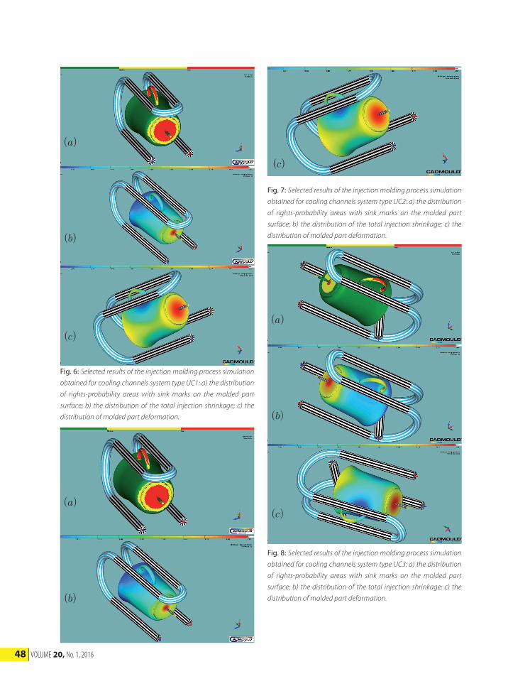
The preliminary simulation results showed that the molding element which required longest cooling time was the cup holder, and therefore the designed cooling system cooling channels are arranged parallel to it. As cooling liquid factor water was used, having a temperature of 20°C, flows through the cooling channels at a rate of 10dm3/min. In the simulation for the cooling system marked UC1 injection molding process parameters were selected in accordance with established based on preliminary simulations, namely the time of the injection phase was 1.52s, and the injection pressure was 40 MPa value. The time the packing phase was 10 seconds and the packing pressure was the same as the injection pressure, and the cooling time of the molded part in the injection die decreased from 30s to 20s in order to reduce cycle time and increase production efficiency. Conditions for filling the cavity have not changed, and therefore no significant differences when filling the cavity were observed: the pressure in the mold cavity was reduced from 10.47MPa to 9.52MPa, the maximum shear rate in the injection phase have a value of 128560s-1 relative to 128567s-1, and the maximum temperature of the material in the cavity decreased slightly from 245.4°C on 244.9°C. After changing the cooling conditions was observed deterioration in the quality of the molding, manifested by an increase in the surface area exposed to the collapse of the surface and the deterioration of dimensional accuracy. The mean value for the whole of the molding shrinkage was 2.2% and the maximum 4.3%, although the shrinkage at the surface of the molding decreased and after the cooling channels of unsatisfactory occurred only at the base of the cup, that is, in a location that is least visible, and not significantly
affect the aesthetics of final part. The distortion curvature of the surface of the molded part varied in the range of -1.025% to 1.183%. The selected simulation results in graphical form are shown in Fig. 6. The cooling system UC2 has a further cooling channel located in the axis of the punch. The additional channel had to increase the intensity of the heat transfer from the inside walls of the cup and the bottom, which was a place exposed to the greatest deformation, and by improving the cooling intensity positively impact on the reduction of the average shrinkage and standardize the temperature distribution of the molded part. The introduction of this modification, while maintaining the same process parameters as for the cooling system UC1 meant that the pressure in the mold cavity to 10.07MPa increased, and the maximum shear rate and the maximum temperature in the mold cavity is slightly changed and were respectively 128558s-1 and 245°C. Shown in Fig. 7a the map of the probability of the pronouncement of sink marks of molded part surface is similar to that achieved in the initial simulations (Fig. 2a). In Fig. 7b and 7c are showing the distribution of shrinkage and deformation of the molded part cooled with using cooling system in variant UC2. Thanks to the additional cooling channel the molded part improved dimensional accuracy, as in this case, the average shrinkage of injection molded part was 1.6%, and the maximum value of total shrinkage is 2.93%. The distortion curvature of the surface of the molded part varied in the range of -0.866% to 0.715%. Therefore reached values close to those of the initial simulation, while significantly reducing the cooling time of the molding of one-third, from 30 to 20 seconds, greatly improving manufacturing efficiency expected.
48 VOLUME 20, No. 1, 2016
( )a
( )b
( )c
Fig. 6: Selected results of the injection molding process simulation
obtained for cooling channels system type UC1: a) the distribution
of rights-probability areas with sink marks on the molded part
surface; b) the distribution of the total injection shrinkage; c) the
distribution of molded part deformation.
( )a
( )b
( )c
Fig. 7: Selected results of the injection molding process simulation
obtained for cooling channels system type UC2: a) the distribution
of rights-probability areas with sink marks on the molded part
surface; b) the distribution of the total injection shrinkage; c) the
distribution of molded part deformation.
( )a
( )b
( )c
Fig. 8: Selected results of the injection molding process simulation
obtained for cooling channels system type UC3: a) the distribution
of rights-probability areas with sink marks on the molded part
surface; b) the distribution of the total injection shrinkage; c) the
distribution of molded part deformation.

Acta Mechanica SlovacaJournal published by Faculty of Mechanical Engineering - Technical University of Košice
49
The cooling system UC3 modified cooling channel in the middle of the punch, increasing its diameter. As a result of this change, while maintaining the injection parameters as in the case of previous two cooling systems, the pressure in the cavity was 10.08MPa value and the maximum shear rate and the maximum temperature in the mold cavity remaining unchanged. Slightly reduced surface area exposed areas severely deformed and remained so at the holder and the bottom of the cup. The maximum shrinkage value fell to 2.89%, while the average value of the shrinkage was still 1.6%. Distortion curvature of the surface of the molded part varied in the range of -0.848% to 0.704%. Modification of UC3 compared to UC2 did not produce significant changes in the course of cooling the molded part and had a negligible impact on changing the dimensional accuracy. Further simulations were not performed, because the expected effect of shortening the molding cooling time (from 30s to 20s) while maintaining the desired accuracy of final part performance was achieved for both the cooling system UC2 and UC3. Selected results of the simulation of injection molding process in the form with a cooling system type UC3 are graphically shown in Fig. 8. The diagrams showed at Fig. 9, Fig. 10 and Fig. 11 present a summary of selected parameters on the dimensional accuracy of the molded part in the case of the variety of cooling system, referred to the results of preliminary simulation without cooling channels.
Fig. 9: Comparison of the average injection shrinkage and total
shrinkage of molded part depending on the type of the cooling
channels.
Fig. 10: Comparison of the maximum warpage and deformation
of molded part depending on the type of the cooling channels.
Fig. 11: Comparison of the primary and total deformation in X, Y
and Z axis of the molded part depending on the type of the cooling
channels.

50 VOLUME 20, No. 1, 2016
4. Conclusions Cadmould program 3D-F allows a detailed analysis of the phenomena occurring during the process of injection molding of polymers. On the basis of the injection molding simulations of the cup-shaped molded part several varieties of cooling system were analyzed from the point of view of the selected parameters characterizing the injection molding process and the size of geometrical features characterizing the molded part. The basic criterion was the efficiency of production which was associated with the optimization of shortening cycle time of injection, modified by changing of the molded part cooling time in the injection die compact, while maintaining a certain dimensional accuracy, affecting the performance or aesthetics of final molded part. Molded part in shape of cup belongs to a group of thin-walled molded parts that are particularly susceptible to deformation and distortion, and therefore it is necessary to analyze the influence of cooling conditions on change size and shape, through the analysis of shrinkage and deformation of the molded part. In the various types of the cooling systems with other construction the differences between the analyzed values were significant in some cases, an example of which can be more than twice as large as the maximum shrinkage and also average shrinkage between the molded part cooling in injection mold without cooling channels and molded part cooled by cooling system UC1 type. Another example is close to twice the difference between the values of the aforementioned features obtained by previous simulation for the cooling system UC1 and UC2 and UC3. In the case of the cooling system UC1 a declining of the pressure in the cavity has been observed by approximately 9% compared to the mold without cooling channels, which after modification of the cooling system and the improved system UC2 and UC3 was respectively 3.8% and 3.7%. Modeling the cooling systems a reducing of the cooling time in the injection die has been obtained by 33.3%, with a change in dimensional accuracy average of 6%, referred to the parameter change of curvature of the part. Another indicator of dimensional accuracy may be comparing the maximum deformation in the molded part axis which for the die without the cooling channels in the X-axis was 0.349mm, 0.918mm Y-axis and Z-axis 0.347mm, whereas in
the case of the mold cooling system UC3 maximum deformation in molded part axis was in the X axis 0.353mm, 1.042mm Y-axis and Z-axis 0.360mm, it’s giving respectively the deterioration of the feature by 1.1%, 11.9% and 3.6% in the appropriate axis. Using the capabilities of software for injection molding simulation the few design solutions of injection die cooling systems were analyzed, in order to shorten the manufacturing time and reach a compromise between accuracy and aesthetics of the product, and the time and effort for its implementation. Using the software to simulate the injection molding process, it’s necessary to remember that the results of computer modeling, though greatly serve to help for designers and technologists still represent only an attempt to present the injection molding process, which occurs within the mold. The simulation results are only a set of guidelines, which take the direction of construction work and must be confronted with actual production capacity and experience of designers.
5. Acknowledgments This paper is the result of the project implementation: Techno-logical and design aspects of extrusion and injection molding of thermoplastic polymer composites and nanocomposites (PIRSES-GA-2010-269177) supported by The international project realized in range of Seventh Frame Programme of European Union (FP7), Marie Curie Actions, PEOPLE, International Research Staff Exchange Scheme (IRSES).
6. References and Notes[1] Annicchiarico D., Alcock D., Alcock J. R.: Review of Factors
that Affect Shrinkage of Molded Part in Injection Molding.
Materials and Manufacturing Processes 2014, 29, 6, 662-682.
[2] Chuang M., Yang Y., Hsiao Y.: Modeling and Optimization of
Injection Molding Process Parameters for Thin-Shell Plastic
Parts. Polymer-Plastics Technology and Engineering 2009,
48, 7, 745-753.
[3] Beaumont J. P., Sherman R., Nagel R. F.: Successful Injection
Molding: Process, Design, and Simulation. Carl Hanser Ver-
lag, Munich 2002.
[4] Kazmer D. O.: Injection Mold Design Engineering. Carl Han-
ser Verlag, Munich 2007.
[5] Bociąga E.: Procesy determinujące przepływ tworzyw w
formie wtryskowej i jego efektywność, Wydawnictwo Po-
litechniki Częstochowskiej, Częstochowa 2001.
[6] Fuh J.Y.H., Fu M. W., Nee A.Y.C.: Computer-Aided Injection
Mold Design and Manufacture. Marcel Dekker Inc., New

Acta Mechanica SlovacaJournal published by Faculty of Mechanical Engineering - Technical University of Košice
51
York, Basel 2004.
[7] Chen Z., Turng L. S.: A review of current developments in
process and quality control for injection molding. Advances
in Polymer Technology 2005, 24, 3, 165–182.
[8] Zhou H.: Computer Modeling for Injection Molding: Simu-
lation, Optimization, and Control. John Wiley & Sons Inc.,
Hoboken 2013.
[9] Bociąga E.: Kryteria wyboru metody wtryskiwania. Polimery
2010, 55, 3, 172-180.
[10] Jones P.: The Mould Design Guide. Smithers Rapra Technol-
ogy Limited, Shawbury 2008.
[11] Matsumori T., Yamazaki K.: Design improvement of cooling
channel layout for plastic injection moulding. Engineering
Optimization 2011, 43, 8, 891-909.
[12] Published online: 2 Feb 2011Rosato D. V., Rosato D. V., Ro-
sato M. G.: Injection Molding Handbook. Kluwer Academic
Publisher, Norwell 2000.
[13] Duleba B., Greškovič F.: Application of CA systems at design
and simulation of plastic molded parts. International Jour-
nal of Advanced Engineering Technology 2012, 3, 4, 1-7.
[14] Cadmoul 3D-F. Instrukcja użytkownika, wersja 5. Simcon
2012 (wersja elektroniczna).
[15] Modi D., Šimáček P., Advani S.: Influence of injection gate
definition on the flow-front approximation in numerical
simulations of mold-filling processes. International Journal
for Numerical Methods in Fluids 2003, 42, 11, 1237–1248.
[16] El Otmani R., Zinet M., Boutaous M., Benhadid H.: Numeri-
cal simulation and thermal analysis of the filling stage in
the injection molding process: Role of the mold-polymer
interface. Journal of Applied Polymer Science 2011, 121, 3,
1579–1592.
[17] Yu L., Koh C. G., Lee L. J., Koelling K. W., Madou M. J.: Experi-
mental investigation and numerical simulation of injection
molding with micro-features. Polymer Engineering & Sci-
ence 2002, 42, 5, 871–888
[18] Zhang Y., Deng Y. M., Sun B. S.: Injection Molding Warpage
Optimization Based on a Mode-Pursuing Sampling Meth-
od. Polymer-Plastics Technology and Engineering 2009, 48,
7, 767-774.
[19] Fen Liu F., Zeng S., Zhou H., Li J.: A study on the distinguish-
ing responses of shrinkage and warpage to processing
conditions in injection molding. Journal of Applied Polymer
Science 2012, 125, 1, 731–744.
[20] Samuel S.: Basic and Intermediate Solid Edge ST5. Model-
ing, Drafting, and Assemblies. Design Visionaries, San Jose
2013.