Numerical Investigation of Non-Newtonian Laminar …€¦ · · 2012-11-09Numerical Investigation...
5
Numerical Investigation of Non-Newtonian Laminar Flow in Curved Tube with Insert A. Kadyyrov 1 1 Research center for power engineering problems Federal government budgetary institution of science Kazan scientific center Russian Academy of Sciences, *Corresponding author: Russia, Kazan, 420111, Lobachevsky St 2/31, In box 190, [email protected] Abstract: Non-Newtonian laminar flows in curved circular tubes with inserts are investigated by computer simulations. 0.65% solution of NaCMC is considered. Three- dimensional incompressible Navier-Stokes equations are solved using COMSOL Multiphysics. Placements of inserts inside the curved tubes and their effects on the hydrodynamics of the flow are studied. Computations are carried out with various values of Reynolds number ranging from 10 to 1000. Keywords: Non-Newtonian, curved, tube, insert. 1. Introduction and Governing Equations. Heat transfer processes are known to depend on hydrodynamic fields. Therefore, the purpose of this research is to study the hydrodynamic fields in curved channels. We consider a steady flow of Non-Newtonian viscous liquids in a curved tube. The mathematical model is developed taking into account a negligibly small gravity force. The steady three-dimensional Navier-Stokes equations are used as the governing equations: T pI u u u u in 0 u in where u=(u1, u2, u3) is the fluid velocity, p is pressure, and are viscosity and density of the fluid respectively. The solution domain Ω (Fig. 1) consists of three parts. The first part is a part of a straight tube of 0.015m long, L1=0.01 m, L2=0.005 m. The second part is a curved region with rotation angle =90º and radius of the curvature R=0.075m. The third part is a part of the straight tube following the curved part. Boundary conditions: in the inlet region of the channel velocity field is fully developed, in the outlet region of the channel normal stress is given (the total stress on the boundary is set equal to a stress vector of magnitude, 0 f 0 oriented in the opposite normal direction). The no-slip condition is forced on the channel walls. We consider two geometric objects. There is a twisted tape insert in the curved part between B and F in Elbow #1 (Fig. 1). Elbow #2 has a twisted tape insert in the straight part of the tube between A and B. The tape is twisted until it reaches an angle of 90 degrees and turns right in both cases. Elbow #1. Elbow #2 Figure 1. Geometric objects, (A), (B),…, (G) – cross- sections, where (С) – 30º cross-section, (D) – 45º cross-section, (E) – 60º cross-section. To describe the viscosity behavior we used the Kutateladze model [1]. It is based on the structural theory of viscosity and its parameters have physical meaning. The rheological properties of Carboxymethyl cellulose (0.65%
Transcript of Numerical Investigation of Non-Newtonian Laminar …€¦ · · 2012-11-09Numerical Investigation...

Numerical Investigation of Non-Newtonian Laminar Flow in Curved Tube with Insert
A Kadyyrov1 1 Research center for power engineering problems Federal government budgetary institution of science Kazan scientific center Russian Academy of Sciences Corresponding author Russia Kazan 420111 Lobachevsky St 231 In box 190 aidarikramblerru Abstract Non-Newtonian laminar flows in curved circular tubes with inserts are investigated by computer simulations 065 solution of NaCMC is considered Three-dimensional incompressible Navier-Stokes equations are solved using COMSOL Multiphysics Placements of inserts inside the curved tubes and their effects on the hydrodynamics of the flow are studied Computations are carried out with various values of Reynolds number ranging from 10 to 1000 Keywords Non-Newtonian curved tube insert 1 Introduction and Governing Equations
Heat transfer processes are known to depend on hydrodynamic fields Therefore the purpose of this research is to study the hydrodynamic fields in curved channels We consider a steady flow of Non-Newtonian viscous liquids in a curved tube The mathematical model is developed taking into account a negligibly small gravity force
The steady three-dimensional Navier-Stokes equations are used as the governing equations TpI uuuu in
0 u in where u=(u1u2u3) is the fluid velocity p is pressure and are viscosity and density of the fluid respectively The solution domain Ω (Fig 1) consists of three parts The first part is a part of a straight tube of 0015m long L1=001 m L2=0005 m The second part is a curved region with rotation angle =90ordm and radius of the curvature R=0075m The third part is a part of the straight tube following the curved part Boundary conditions in the inlet region of the channel velocity field is fully developed in the outlet region of the channel normal stress is given (the total stress on the boundary is set equal to a stress vector of magnitude 0 f0
oriented in the opposite normal direction) The no-slip condition is forced on the channel walls
We consider two geometric objects There is a twisted tape insert in the curved part between B and F in Elbow 1 (Fig 1) Elbow 2 has a twisted tape insert in the straight part of the tube between A and B The tape is twisted until it reaches an angle of 90 degrees and turns right in both cases
Elbow 1
Elbow 2
Figure 1 Geometric objects (A) (B)hellip (G) ndash cross-sections where (С) ndash 30ordm cross-section (D) ndash 45ordm cross-section (E) ndash 60ordm cross-section
To describe the viscosity behavior we used
the Kutateladze model [1] It is based on the structural theory of viscosity and its parameters have physical meaning The rheological properties of Carboxymethyl cellulose (065
NaCMC) depend on strain and do not depend on their previous history
)exp( (3) where 0
01 2II 221 21 I1 is fluidity 0 - fluidity
when 0 respectively is a measure of the structural stability of the fluid 1 is yield stress 2
2 tr4I D is the second invariant of the strain rate tensor In addition =0 corresponds to a Newtonian fluid 0 corresponds to a dilatant fluid 0 corresponds to a pseudo-plastic fluid
The three-dimensional incompressible Navier-Stokes equations are solved using COMSOL Multiphysics To solve linear system equations we used ldquoDirect (PARDISO)rdquo In our computations we examined Sodium Carboxymethyl cellulose (065 NaCMC) (Fig 2) This fluid is one of the widely used as a non-Newtonian fluid
Figure 2 Dependence of dynamic viscosity (Pas) on the second invariant of the strain rate tensor (s-2) for Sodium Carboxymethyl cellulose (065 NaCMC) T=303K
An actual engineering problem is used to
validate the code of COMSOL Multiphysics and partitioning mesh The experimental results of Muguercia et al [2] are compared with the simulated data obtained numerically In these laboratory tests a 180ordm U-tube with the straight tube preceding its inlet ensures that flow is fully developed The U-tube has the radius of curvature R = 635 cm and the radius of the cross section a=11 cm Fully developed flow condition is simulated with Reynolds numbers of 1000 which correspond to Dean numbers of 416 The fluid being tested (58-60 benzyl alcohol in 95 ethyl alcohol) has a density of 0931 gcm3 and an absolute viscosity of about
003 gcmsec Mesh generation starts with a coarse initial mesh The volume of the mesh is then improved by refining the initial mesh step by step The refinement process is controlled by calculation of the integral value of velocity at the cross-section (D) The refinement process is finished when the relative error becomes less than 0001 In this case the mesh consists of 241408 elements The computations are performed on the computer Intelreg CoreTM i7 950 with 24Gb RAM A comparison is presented in Fig 3
(a)
(b)
(c)
Figure 3 The distribution of relative velocity at the cross section a) at the entrance b) at the 90ordm cross section c) at the 180ordm cross-section continuous line - numerical result diamonds - numerical result of Guan Xiaofeng [3] triangles - experimental result of Muguercia [2]
2 Numerical Results
Numerical computations are carried out with the help of COMSOL Multiphysics using
Lagrange P2P1 elements over a trihedral mesh The computational mesh consists of 220342 and 220322 elements for elbow 1 and elbow 2 respectively The twisted tapes are designed and then imported from MatLab The calculations are performed for = 1012 kgcm3 and the temperature 303K On the Fig 4 are presented the velocity field
outer wall outer wall
inner wall inner wall
(a) (b) outer wall outer wall
inner wall inner wall
(c) (d) outer wall outer wall
inner wall inner wall
(e) (f) outer wall outer wall
inner wall inner wall
(g) (h) Figure 4 The velocity field in various cross-sections of the curved channel with inserts (а) at cross-section C Elbow 1 (b) at cross-section C Elbow 2 (c) at cross-section D Elbow 1 (d) at cross-section D Elbow 2 (e) at cross-section E Elbow 1 (f) at cross-section E Elbow 2 (g) at cross-section F Elbow 1 (h) at cross-section F Elbow 2 Re=1039
In the curved channel the fluid particles with different speeds are subjected to different effects of centrifugal forces Due to these forces maximum speed tends to the outer wall of the curved tube Numerical results show that due to the twisted tape inserted into the curved part of the channel additional inertial forces appear Therefore the fluid flow moves quicker to the outer walls of the channel passing throughout the curved part (Elbow 1) If there is the insert in front of the curved part additional inertial forces contribute to the fact that the region with the maximum speed is achieved in the central part of the curved channel from section C to E (Elbow 1)
The region of maximum pressure is known to be located on the outer wall of the curved tube (Fig 5 c f i) and remains virtually unchanged throughout its length
outer wall outer wall outer wall
inner wall inner wall inner wall (a) (b) (c)
outer wall outer wall outer wall
inner wall inner wall inner wall (d) (e) (f)
outer wall outer wall outer wall
inner wall inner wall inner wall (g) (h) (i)
Figure 5 Pressure distribution in various cross-sections of the curved channel with inserts (а) at cross-section C Elbow 1 (b) at cross-section C Elbow 2 (c) at cross-section C curved channel without inserts [4] (d) at cross-section D Elbow 1 (e) at cross-section D Elbow 2 (f) at cross-section D curved channel without inserts [4] (g) at cross-section F Elbow 1 (h) at cross-section F Elbow 2 (i) at cross-section F the curved channel without inserts [4] Re=1039
Moreover the maximum value itself varies and reaches its maximum in section D The presence of inserts inside the curved tube alters the pressure distribution and its maximum value In Elbow 1 the region of maximum pressure is somewhat moved from the outer wall but the maximum value is much higher than the values in tubes without inserts In Elbow 2 though the pressure distribution is asymmetrical in general it follows the distribution in the tube without inserts It should be emphasized that maximum pressure in this case is lower than corresponding values in tubes without inserts (for example in section D a decrease of the maximum pressure on the outer wall reaches 8)
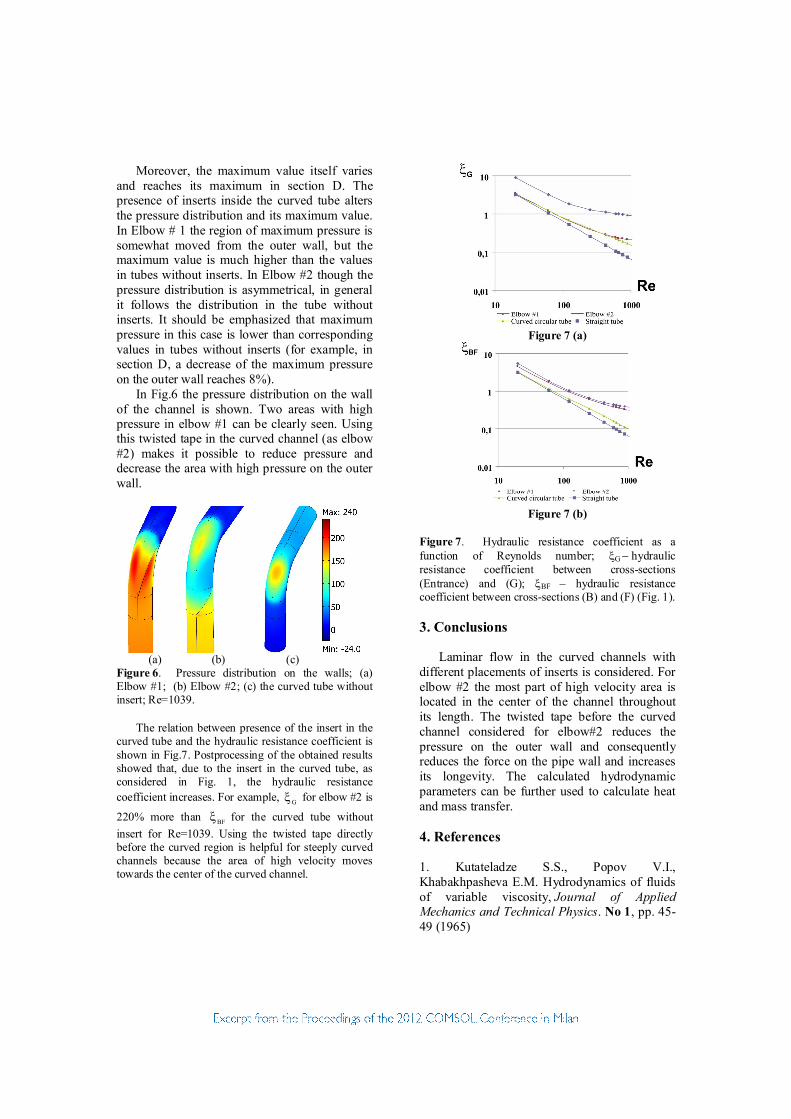
In Fig6 the pressure distribution on the wall of the channel is shown Two areas with high pressure in elbow 1 can be clearly seen Using this twisted tape in the curved channel (as elbow 2) makes it possible to reduce pressure and decrease the area with high pressure on the outer wall
(a) (b) (c) Figure 6 Pressure distribution on the walls (a) Elbow 1 (b) Elbow 2 (c) the curved tube without insert Re=1039
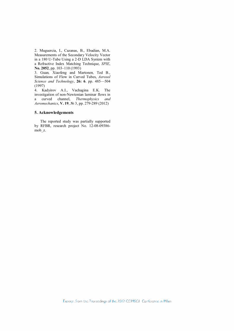
The relation between presence of the insert in the
curved tube and the hydraulic resistance coefficient is shown in Fig7 Postprocessing of the obtained results showed that due to the insert in the curved tube as considered in Fig 1 the hydraulic resistance coefficient increases For example G for elbow 2 is
220 more than BF for the curved tube without insert for Re=1039 Using the twisted tape directly before the curved region is helpful for steeply curved channels because the area of high velocity moves towards the center of the curved channel
Figure 7 (a)
Figure 7 (b)
Figure 7 Hydraulic resistance coefficient as a function of Reynolds number Ghydraulic resistance coefficient between cross-sections (Entrance) and (G) BF ndash hydraulic resistance coefficient between cross-sections (B) and (F) (Fig 1) 3 Conclusions
Laminar flow in the curved channels with different placements of inserts is considered For elbow 2 the most part of high velocity area is located in the center of the channel throughout its length The twisted tape before the curved channel considered for elbow2 reduces the pressure on the outer wall and consequently reduces the force on the pipe wall and increases its longevity The calculated hydrodynamic parameters can be further used to calculate heat and mass transfer 4 References 1 Kutateladze SS Popov VI Khabakhpasheva EM Hydrodynamics of fluids of variable viscosity Journal of Applied Mechanics and Technical Physics No 1 pp 45-49 (1965)
2 Muguercia I Cazanas B Ebadian MA Measurements of the Secondary Velocity Vector in a 180 U-Tube Using a 2-D LDA System with a Refractive Index Matching Technique SPIE No 2052 pp 103ndash110 (1993) 3 Guan Xiaofeng and Martonen Ted B Simulations of Flow in Curved Tubes Aerosol Science and Technology 26 6 pp 485mdash504 (1997) 4 Kadyirov AI Vachagina EK The investigation of non-Newtonian laminar flows in a curved channel Thermophysics and Aeromechanics V 19 3 pp 279-289 (2012) 5 Acknowledgements
The reported study was partially supported by RFBR research project No 12-08-09386-mob_z

NaCMC) depend on strain and do not depend on their previous history
)exp( (3) where 0
01 2II 221 21 I1 is fluidity 0 - fluidity
when 0 respectively is a measure of the structural stability of the fluid 1 is yield stress 2
2 tr4I D is the second invariant of the strain rate tensor In addition =0 corresponds to a Newtonian fluid 0 corresponds to a dilatant fluid 0 corresponds to a pseudo-plastic fluid
The three-dimensional incompressible Navier-Stokes equations are solved using COMSOL Multiphysics To solve linear system equations we used ldquoDirect (PARDISO)rdquo In our computations we examined Sodium Carboxymethyl cellulose (065 NaCMC) (Fig 2) This fluid is one of the widely used as a non-Newtonian fluid
Figure 2 Dependence of dynamic viscosity (Pas) on the second invariant of the strain rate tensor (s-2) for Sodium Carboxymethyl cellulose (065 NaCMC) T=303K
An actual engineering problem is used to
validate the code of COMSOL Multiphysics and partitioning mesh The experimental results of Muguercia et al [2] are compared with the simulated data obtained numerically In these laboratory tests a 180ordm U-tube with the straight tube preceding its inlet ensures that flow is fully developed The U-tube has the radius of curvature R = 635 cm and the radius of the cross section a=11 cm Fully developed flow condition is simulated with Reynolds numbers of 1000 which correspond to Dean numbers of 416 The fluid being tested (58-60 benzyl alcohol in 95 ethyl alcohol) has a density of 0931 gcm3 and an absolute viscosity of about
003 gcmsec Mesh generation starts with a coarse initial mesh The volume of the mesh is then improved by refining the initial mesh step by step The refinement process is controlled by calculation of the integral value of velocity at the cross-section (D) The refinement process is finished when the relative error becomes less than 0001 In this case the mesh consists of 241408 elements The computations are performed on the computer Intelreg CoreTM i7 950 with 24Gb RAM A comparison is presented in Fig 3
(a)
(b)
(c)
Figure 3 The distribution of relative velocity at the cross section a) at the entrance b) at the 90ordm cross section c) at the 180ordm cross-section continuous line - numerical result diamonds - numerical result of Guan Xiaofeng [3] triangles - experimental result of Muguercia [2]
2 Numerical Results
Numerical computations are carried out with the help of COMSOL Multiphysics using
Lagrange P2P1 elements over a trihedral mesh The computational mesh consists of 220342 and 220322 elements for elbow 1 and elbow 2 respectively The twisted tapes are designed and then imported from MatLab The calculations are performed for = 1012 kgcm3 and the temperature 303K On the Fig 4 are presented the velocity field
outer wall outer wall
inner wall inner wall
(a) (b) outer wall outer wall
inner wall inner wall
(c) (d) outer wall outer wall
inner wall inner wall
(e) (f) outer wall outer wall
inner wall inner wall
(g) (h) Figure 4 The velocity field in various cross-sections of the curved channel with inserts (а) at cross-section C Elbow 1 (b) at cross-section C Elbow 2 (c) at cross-section D Elbow 1 (d) at cross-section D Elbow 2 (e) at cross-section E Elbow 1 (f) at cross-section E Elbow 2 (g) at cross-section F Elbow 1 (h) at cross-section F Elbow 2 Re=1039
In the curved channel the fluid particles with different speeds are subjected to different effects of centrifugal forces Due to these forces maximum speed tends to the outer wall of the curved tube Numerical results show that due to the twisted tape inserted into the curved part of the channel additional inertial forces appear Therefore the fluid flow moves quicker to the outer walls of the channel passing throughout the curved part (Elbow 1) If there is the insert in front of the curved part additional inertial forces contribute to the fact that the region with the maximum speed is achieved in the central part of the curved channel from section C to E (Elbow 1)
The region of maximum pressure is known to be located on the outer wall of the curved tube (Fig 5 c f i) and remains virtually unchanged throughout its length
outer wall outer wall outer wall
inner wall inner wall inner wall (a) (b) (c)
outer wall outer wall outer wall
inner wall inner wall inner wall (d) (e) (f)
outer wall outer wall outer wall
inner wall inner wall inner wall (g) (h) (i)
Figure 5 Pressure distribution in various cross-sections of the curved channel with inserts (а) at cross-section C Elbow 1 (b) at cross-section C Elbow 2 (c) at cross-section C curved channel without inserts [4] (d) at cross-section D Elbow 1 (e) at cross-section D Elbow 2 (f) at cross-section D curved channel without inserts [4] (g) at cross-section F Elbow 1 (h) at cross-section F Elbow 2 (i) at cross-section F the curved channel without inserts [4] Re=1039
Moreover the maximum value itself varies and reaches its maximum in section D The presence of inserts inside the curved tube alters the pressure distribution and its maximum value In Elbow 1 the region of maximum pressure is somewhat moved from the outer wall but the maximum value is much higher than the values in tubes without inserts In Elbow 2 though the pressure distribution is asymmetrical in general it follows the distribution in the tube without inserts It should be emphasized that maximum pressure in this case is lower than corresponding values in tubes without inserts (for example in section D a decrease of the maximum pressure on the outer wall reaches 8)
In Fig6 the pressure distribution on the wall of the channel is shown Two areas with high pressure in elbow 1 can be clearly seen Using this twisted tape in the curved channel (as elbow 2) makes it possible to reduce pressure and decrease the area with high pressure on the outer wall
(a) (b) (c) Figure 6 Pressure distribution on the walls (a) Elbow 1 (b) Elbow 2 (c) the curved tube without insert Re=1039
The relation between presence of the insert in the
curved tube and the hydraulic resistance coefficient is shown in Fig7 Postprocessing of the obtained results showed that due to the insert in the curved tube as considered in Fig 1 the hydraulic resistance coefficient increases For example G for elbow 2 is
220 more than BF for the curved tube without insert for Re=1039 Using the twisted tape directly before the curved region is helpful for steeply curved channels because the area of high velocity moves towards the center of the curved channel
Figure 7 (a)
Figure 7 (b)
Figure 7 Hydraulic resistance coefficient as a function of Reynolds number Ghydraulic resistance coefficient between cross-sections (Entrance) and (G) BF ndash hydraulic resistance coefficient between cross-sections (B) and (F) (Fig 1) 3 Conclusions
Laminar flow in the curved channels with different placements of inserts is considered For elbow 2 the most part of high velocity area is located in the center of the channel throughout its length The twisted tape before the curved channel considered for elbow2 reduces the pressure on the outer wall and consequently reduces the force on the pipe wall and increases its longevity The calculated hydrodynamic parameters can be further used to calculate heat and mass transfer 4 References 1 Kutateladze SS Popov VI Khabakhpasheva EM Hydrodynamics of fluids of variable viscosity Journal of Applied Mechanics and Technical Physics No 1 pp 45-49 (1965)
2 Muguercia I Cazanas B Ebadian MA Measurements of the Secondary Velocity Vector in a 180 U-Tube Using a 2-D LDA System with a Refractive Index Matching Technique SPIE No 2052 pp 103ndash110 (1993) 3 Guan Xiaofeng and Martonen Ted B Simulations of Flow in Curved Tubes Aerosol Science and Technology 26 6 pp 485mdash504 (1997) 4 Kadyirov AI Vachagina EK The investigation of non-Newtonian laminar flows in a curved channel Thermophysics and Aeromechanics V 19 3 pp 279-289 (2012) 5 Acknowledgements
The reported study was partially supported by RFBR research project No 12-08-09386-mob_z