Numerical Evalu ation of the Mechanical Behavio r of a ...
9
International Journal of Composite Materials 2013, 3(4): 83-91 DOI: 10.5923/j.cmaterials.20130304.01 Numerical Evaluation of the Mechanical Behavior of a Particulate Composite Material as Reinforcement in Timber Beams Júlio Cés ar Fe rre ira Braz 1,* , Roberto Bianchini Layber 1 , Carlos He nrique Lauro 2 , André Luis Christoforo 1 , Túlio Hallak Panzera 1 , Francisco Antonio Rocco Lahr 3 , Vânia Regina Velloso Silva 1 1 Departmentof Mechanical Engineering, Federal University of SãoJoão del-Rei, São João del-Rei, 36307-352, Brazil 2 Department of Mechanical Engineering, University of Aveiro, Aveiro, 3810-193, Portugal 3 Department ofStructural Engineering, Engineering Schoolof SãoCarlos (EESC/USP), São Carlos, 13566-590, Brazil Abstract Beams are structural elements commonly used in structure for construction designs. The use of wood as structural elements is very important because it is a material of renewable source, low density and satisfactory mechanical performance. When the wood surface is not properly treated, the structure can be destroyed not only by environmental conditions but also the attack of insects compromising the design. This research aimed to evaluate the mechanical performance of the use of a particulate composite material (epoxy resin and structural Portland cement) as a way of reinforcing beams. The study of the mechanical performance of using this material in timber beams is essentially numerical, based on the Finite Element Method, by using the static four points bending tests. The wood used in the simulation was the Eucalyptus grandis, and their mechanical properties were obtained from specialized literature in the area of timber structures. The results for displacements and stresses obtained from numerical analysis indicated that the composite material was able with successfully withstand the stresses caused by the loads, the same occurring with the wood, and the results of the hypothesis test for equivalence between meansrevelledtobeminor the influence ofPoisson's ratioon calculus of the displacements. Keywords Composite, Wooden Beams, Structural Reinforcement, Finite Element Method 1. Introduction Beams are structural elements present in most structural designs[1]. In terms of civil and rural construction, highlight the use of wood, being a renewable source material, having as one of its main features the excellent relationship between strength and density, according Calil et al.[2], that is four times higher when compared to steel. The timber in general also use as essential part in building structures, present in bridges[3], flooring, roofing and other applications. However, the conduct of some construction details combined exposure to different environmental conditions influence the durability of the structural elements[4], required techniques to repair or reinforce damaged structures. Besides the condition of reinforcement structures already designed, the use of reinforcing materials in structural design * Corresponding author: [email protected] (Júlio César Ferreira Braz) Published online at http://journal.sapub.org/cmaterials Copyright © 2013 Scientific & Academic Publishing. All Rights Reserved to be executed increases the potential use of structural components made of wood, which according Miotto and Dias[5], the low modulus of elasticity of wood when compared to other structural materials, causes deformations are limiting factors in a project of wooden beams. According to Fiorelli[6], timber structures require both repairs to restore the compromised structure and to increase the load capacity of its structural elements (reinforcement). According to Fiorelli[7], problems related to the low efficiency of structural elements, the increased overhead and degradation by aging are very frequently in construction, encouraging the development of research involving the study of structural reinforcements and recovery. Recently, alternative materials have been used to recover and reinforcing structures, highlighting the use of composite materials, especially those prepared with polymers and fiber, flexible materials that are highly strength and can replace with advantage, in some cases, the conventional techniques of reinforcement such as employment and repairs by steel screws[5]. 1.1. Repair and Reinforcement in Wooden Beams
Transcript of Numerical Evalu ation of the Mechanical Behavio r of a ...
International Journal of Composite Materials 2013, 3(4): 83-91 DOI: 10.5923/j.cmaterials.20130304.01
Numerical Evaluation of the Mechanical Behavior of a Particulate Composite Material as Reinforcement in
Timber Beams
Júlio César Ferreira Braz1,*, Roberto Bianchini Layber1, Carlos Henrique Lauro2, André Luis Christoforo1, Túlio Hallak Panzera1, Francisco Antonio Rocco Lahr3,
Vânia Regina Velloso Silva1
1Departmentof Mechanical Engineering, Federal University of SãoJoão del-Rei, São João del-Rei, 36307-352, Brazil 2Department of Mechanical Engineering, University of Aveiro, Aveiro, 3810-193, Portugal
3Department ofStructural Engineering, Engineering Schoolof SãoCarlos (EESC/USP), São Carlos, 13566-590, Brazil
Abstract Beams are structural elements commonly used in structure for construction designs. The use of wood as structural elements is very important because it is a material of renewable source, low density and satisfactory mechanical performance. When the wood surface is not properly treated, the structure can be destroyed not only by environmental conditions but also the attack of insects compromising the design. This research aimed to evaluate the mechanical performance of the use of a particulate composite material (epoxy resin and structural Portland cement) as a way of reinforcing beams. The study of the mechanical performance of using this material in timber beams is essentially numerical, based on the Finite Element Method, by using the static four points bending tests. The wood used in the simulation was the Eucalyptus grandis, and their mechanical properties were obtained from specialized literature in the area of timber structures. The results for d isplacements and stresses obtained from numerical analysis indicated that the composite material was able with successfully withstand the stresses caused by the loads, the same occurring with the wood, and the results of the hypothesis test for equivalence between meansrevelledtobeminor the influence ofPo isson's ratioon calculus of the displacements.
Keywords Composite, Wooden Beams, Structural Reinforcement, Fin ite Element Method
1. Introduction Beams are structural elements present in most structural
designs[1]. In terms of civ il and rural construction, highlight the use of wood, being a renewable source material, having as one of its main features the excellent relationship between strength and density, according Calil et al.[2], that is four times higher when compared to steel.
The timber in general also use as essential part in build ing structures, present in bridges[3], flooring, roofing and other applications. However, the conduct of some construction details combined exposure to different environmental conditions influence the durability of the structural elements[4], required techniques to repair or rein force damaged structures.
Besides the condition of reinforcement structures already designed, the use of reinforcing materials in structural design
* Corresponding author: [email protected] (Júlio César Ferreira Braz) Published online at http://journal.sapub.org/cmaterials Copyright © 2013 Scientific & Academic Publishing. All Rights Reserved
to be executed increases the potential use of structural components made of wood, which according Miotto and Dias[5], the low modulus of elasticity of wood when compared to other structural materials, causes deformations are limit ing factors in a project of wooden beams.
According to Fiorelli[6], timber structures require both repairs to restore the compromised structure and to increase the load capacity of its structural elements (reinforcement). According to Fiorelli[7], problems related to the low efficiency of structural elements, the increased overhead and degradation by aging are very frequently in construction, encouraging the development of research involving the study of structural reinforcements and recovery.
Recently, alternative materials have been used to recover and reinforcing structures, highlighting the use of composite materials, especially those prepared with polymers and fiber, flexib le materials that are highly strength and can replace with advantage, in some cases, the conventional techniques of reinforcement such as employment and repairs by steel screws[5].
1.1. Repair and Reinforcement in Wooden Beams
84 Júlio César Ferreira Braz et al. : Numerical Evaluation of the Mechanical Behavior of a Particulate Composite Material as Reinforcement in Timber Beams
The ideas of strengthening timber structures are not new and over time these have been developed and improved. According Mettem and Robinson[8], among the methods employed in the recovery of timber structures stand out Traditional, wherein the structure is retrieved with new parts which replace degraded, with dimensions and properties similar to the originals, Mechanical, wherein the structural repairs are made using metal connectors and Method Adhesive, where variat ions resin are used in combination with structural reinforcements.
Many studies using the adhesive method have been conducted in the field of rehabilitation and strengthening, particularly with regard to the materials used in strengthening and enhancing interaction/beam[9].
According Ritter[10], the most efficient technique for retriev ing pieces of wood is one that uses epoxy resin. The epoxy putty gel is a readily malleable, can be injected manually into the damaged parts, which increases the mechanical strength of the structural element. Th is material is used to fill cracks surface (attacked by insects) and voids. The epoxy seal beyond the damaged area, reducing the appearance of future cracks, further increase the load capacity of the structure.
Aiming to study the repair and reinforcement for wooden beams, many studies are being developed, emphasizing the use of fiber reinforced polymers.
Fiorelli[7] analysed experimentally the mechanical performance of employing fiber-rein forced polymers (FRP) glued along the tensile region of wooden beams of the Pinus elliottii and Eucalyptus grandis species. In addit ion to other results, the authors concluded that the technique developed turned out to be of simple application and presents an interesting feature, the presence of a large deformation before rupture, justified by lowering the neutral axis, causing crushing of a large amount of wood in the compressed portion.
Miotto and Dias[5] discuss the use of natural fibers (sisal fiber) as a way of strengthening beams in g lued laminated timber (MLC), showing up as a favourable alternative for a better use of forest resources in Brazil. The authors conclude, among others, that the addition of fibers pulled on the face of the wood ensures excellent mechanical performance in bending, however, being modest contribution in terms of stiffness. Also discuss the strength of the MLC can be improved by adding fibers (glass or carbon) in the tensile region, resulting in increased reliability of the material and a reduction of 30% to 40% in volume of wood used. Add also that the reinforcement applied at a rate of 2% to 3% may increase the flexural beams MLC over 100%.
In this context, Campilho et al.[11] evaluated experimentally the influence of the use of laminated composite materials with carbon fibers to reinforce timber beams. Therefore, the authors used the four points static bending, simulating the presence of the defect with the removal of a portion of wood (Pinus Pinaster) over the region requested by tensile stresses (upper and midpoint along the length of the beam). The results of experimental
analysis revealed that the laminated composite, designed to tensile stresses, inserted in the same region as requested by compressive stresses, but still was able to increase the mechanical strength of the assembly.
Besides the work of Campilho et al.[11], carbon fibers as reinforcement in the form of wooden beams have also been the focus of experimental research carried out by Borri et al.[12] and Jankowski et al.[13], being observed in all cases the efficiency of use of material as a reinforcement in structural wood.
Thinking of alternative efficient and practical applicat ions, this paper proposes the use of a polymer-ceramic composite (designed to withstand compressive forces) to be inserted into timber beams (in compressed regions) as a way to repair and reinforcement, as done in the work developed by Christoforo et al.[1]. For be inserted into compressed regions, the condition of the interface between materials is not as significant, because it is the composite contained in the wood.
The evaluation of the efficiency of the use of the composite (epoxy resin and white Portland cement) as reinforcement in this work is essentially numerical, based on the Finite Element Method, and the properties of the composite extracted from the research developed by Panzera et al.[14], and the wood (Eucalyptus grandis) from the Brazilian standard ABNT NBR 7190[15].
In numerical simulat ions (four points static bending), held at the condition of small displacements (L/200, L-length of the beam), as the Brazilian standard ABNT NBR 7190[15] to the suggest to verify the limit state use, the anisotropy of wood is ignored (usual case) and were used in alleviating coefficients on the mechanical properties[15], allowing investigate whether the strength of the wood and composite material were outdate or not in service conditions and the behaviour of the normal stresses acting on the interface between then.
1.2. Polymer-Ceramic Composite
The use and development of polymeric cementit ious products have been conducted in several countries for over forty years. Adding polymer to the cement paste has become the focus of numerous studies in Japan and Europe in the 70s and later, in the 80s in the United States[16]. These composites have been employed in construction in the fin ishing phase but also in the production of precast products.
Recently, a new demand for polymer composites resurfaced, and a clear example of this is the increasing production of artificial marble and granite each year. This activity is being driven by the concepts of sustainability of the century, since the use of mineral rocks for making coatings in construction, promotes the consumption of mineral source and causes serious environmental problems [17].
In terms of microstructure, the polymer phase tends to coat the anhydrite cement grains, slowing the hydration process partly or completely. In some cases, product formation
International Journal of Composite Materials 2013, 3(4): 83-91 85
promotes greater internal than external products of C3S and avoids the format ion of ettringite crystals during the init ial hydration[17, 18]. However, it is quite possible that the biggest advantage of these systems consists in reducing the porosity, with consequent reduction of free paths for crack propagation and increase the strength.
Ohama[19] and Van Gemert et. al.[16] rev iewed several types of polymeric cementitious composites and it is noteworthy that not only the polymer phase is added to cement, but also a percentage of water to promote hydration of the cement grains.
As previously mentioned, the mechanical properties of the composite polymer-ceramic materials used for computer simulations of their employment as reinforcing in the timber beams were obtained from research conducted by Panzera et al.[14]. On ly one reference fo rmulat ion, i.e. pure cement paste was prepared with water for comparison. The cementit ious composites of this study were made with the following proportions of polymeric phase: 100% (0% of cement), 75%, 50%, 25% and 0% (100% of cement). The experimental conditions investigated in the work of Panzera et al.[14] can be seen in Table 1.
Table 1. Experimental conditions. Source: Panzera et al.[14]
Polimer (%) Cement (%) Water (%)
C1 100 0 0
C2 75 25 0
C3 50 50 0
C4 25 75 0
C5 0 100 30
The Portland cement used in the work Panzera et al. (2010) was the CPB-40, manufacturer by Cauê - Brazilian industry. Already the epoxy resin consists of two parts, one called araldite and another hardener. The araldite 1564BR LY and hardener Aradur 2954 was used. The mixing ratio by mass used was 74% of Araldite to 26% of hardener.
Seven specimens were made for each experimental condition for axial compression tests. The tests were performed randomly. The composites were measured investigated for a curing period of 28 days. The modulus of elasticity and compressive strength were determined according to the obtained stress-strain graphs of compression tests. The volume density of the composites was calculated by dividing the dry weight of the composite (after 24 hours in an oven at 105°C) by the volume of the samples (28mm in diameter and 56mm height).
Table 2 shows the averages and standard deviations (SD) of the results of compressive strength (Rc), longitudinal modulus of elasticity (E) and bulk density (Dv) of the experimental conditions investigated in the work of Panzera et al.[14].
The material selected for the simulat ion was the composite C3 (Tab le 2), constituted by 50% of polymeric phase and
50% cementitious phase. The relationship between bulk density and mechanical strength presented by this composite was found to be very promising, exh ibit ing high strength, low density, and high tenacity when compared with the composites of C4 and C5 conditions.
Table 2. Average and standard deviations values of the experimental conditions investigated.Source: Panzera et al.[14]
Condition Rc (MPa) DP
C1 64,33 0,23
C2 67,07 0,56
C3 98,80 2,11
C4 81,73 2,55
C5 28,93 1,90
Condition E (GPa) DP
C1 23,76 1,43
C2 25,29 1,52
C3 33,98 4,69
C4 46,27 4,65
C5 47,88 1,63
Condition Dv (g/cm3) DP
C1 1,17 0,01
C2 1,34 0,02
C3 1,64 0,01
C4 1,84 0,02
C5 1,92 0,03
2. Materials and Methods The wood adopted for the simulations was the Eucalyptus
grandis, for being among the woods catalogued by the Brazilian standard ABNT NBR 7190[15], the renewable character and presents a growing demand in its application.
For the numerical evaluation of wood becomes necessary to know the modulus of elasticity in bending (Em), compressive strength parallel to the grain (fc,0) and tensile strength parallel to the grain (ft, 0), therefore, these variables were obtained from the Brazilian standard[15]. The tensile strength and parallel compression of Eucalyptus wood are respectively equal to fc,0=40.3MPa and ft,0=70.2MPa. The item: Mechanical Properties of this standard presents a ratio between the modulus of elasticity in bending with the modulus of elasticity in compression parallel to the grain (Ec,0), that for d icots, such as Eucalyptus, is expressed by Em=0,90·Ec,0. The value of the modulus of elasticity in compression parallel to the grain of the Eucalyptus wood is equal to Ec,0=12813MPa, resulting in a bending modulus of elasticity of 11531.7MPa.
Assuming the partial coefficient of modification kmod,1=0,6, kmod,2=1,0 e kmod,3=1,0 comes to the value of the total coefficient of modification kmod=0,6. The effective value of the modulus of elasticity in bending (Em,ef) is
86 Júlio César Ferreira Braz et al. : Numerical Evaluation of the Mechanical Behavior of a Particulate Composite Material as Reinforcement in Timber Beams
expressed by Em,ef = kmod·Em=6919,02MPa. From the value of the weighting coefficient (γw) is possible to determine the calculations values of the compression and tensile strength parallel to the grain (fc0,dand ft0,d) through the relation fd=(kmod.f)/γw. Thus were obtained the values fc0,d=17,27MPa and ft0,d =23,4MPa, which respectively represent the calculations values of the compression and tensile strength.
Still on the wood, as mentioned previously, it is treated as isotropic material, is considered null the value of Poisson's ratio of wood in the simulat ions, also known of its small influence in structural timber projects. The value of the Poisson coefficient (0.35) to the composite was used as the epoxy resin[20].
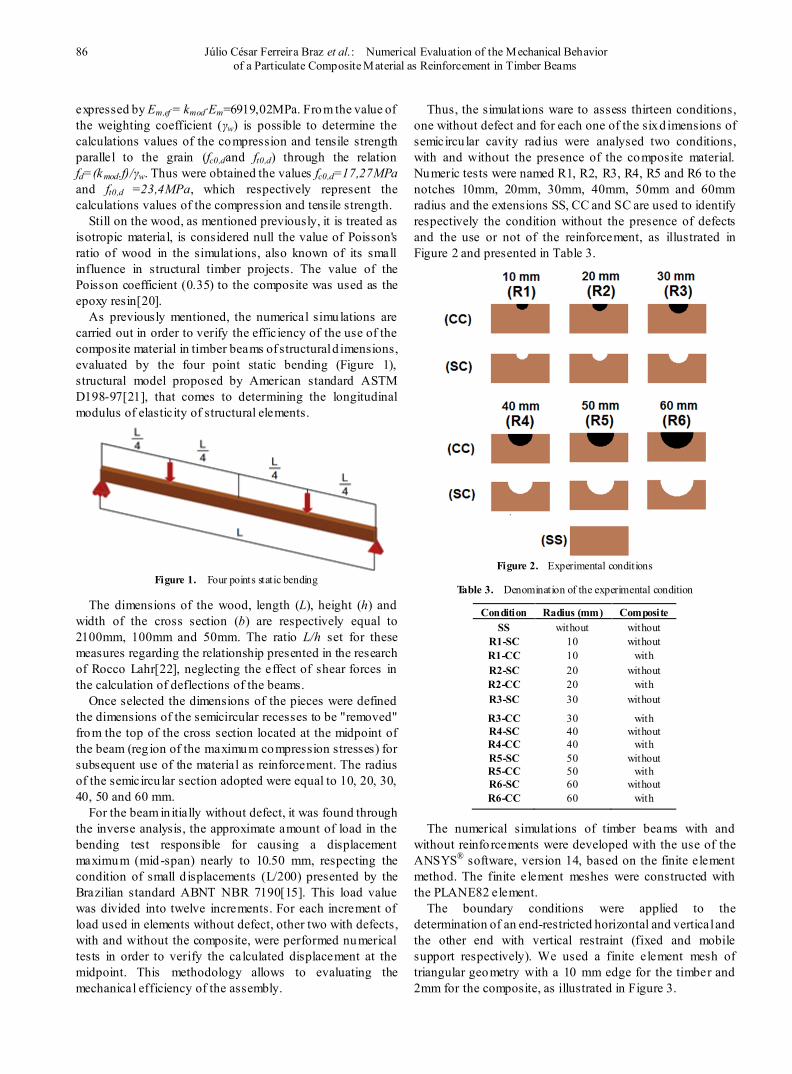
As previously mentioned, the numerical simulations are carried out in order to verify the efficiency of the use of the composite material in timber beams of structural d imensions, evaluated by the four point static bending (Figure 1), structural model proposed by American standard ASTM D198-97[21], that comes to determining the longitudinal modulus of elasticity of structural elements.
Figure 1. Four points static bending
The dimensions of the wood, length (L), height (h) and width of the cross section (b) are respectively equal to 2100mm, 100mm and 50mm. The ratio L/h set for these measures regarding the relationship presented in the research of Rocco Lahr[22], neglecting the effect of shear forces in the calculation of deflections of the beams.
Once selected the dimensions of the pieces were defined the dimensions of the semicircular recesses to be "removed" from the top of the cross section located at the midpoint of the beam (reg ion of the maximum compression stresses) for subsequent use of the material as reinforcement. The radius of the semicircu lar section adopted were equal to 10, 20, 30, 40, 50 and 60 mm.
For the beam in itially without defect, it was found through the inverse analysis, the approximate amount of load in the bending test responsible for causing a displacement maximum (mid-span) nearly to 10.50 mm, respecting the condition of small d isplacements (L/200) presented by the Brazilian standard ABNT NBR 7190[15]. This load value was divided into twelve increments. For each increment of load used in elements without defect, other two with defects, with and without the composite, were performed numerical tests in order to verify the calculated displacement at the midpoint. This methodology allows to evaluating the mechanical efficiency of the assembly.
Thus, the simulat ions ware to assess thirteen conditions, one without defect and for each one of the six d imensions of semicircu lar cavity rad ius were analysed two conditions, with and without the presence of the composite material. Numeric tests were named R1, R2, R3, R4, R5 and R6 to the notches 10mm, 20mm, 30mm, 40mm, 50mm and 60mm radius and the extensions SS, CC and SC are used to identify respectively the condition without the presence of defects and the use or not of the reinforcement, as illustrated in Figure 2 and presented in Table 3.
Figure 2. Experimental conditions
Table 3. Denomination of the experimental condition
Condition Radius (mm) Composite SS without without
R1-SC 10 without R1-CC 10 with R2-SC 20 without R2-CC 20 with R3-SC 30 without
R3-CC R4-SC R4-CC R5-SC R5-CC R6-SC R6-CC
30 40 40 50 50 60 60
with without
with without
with without
with
The numerical simulat ions of timber beams with and without reinforcements were developed with the use of the ANSYS® software, version 14, based on the finite element method. The finite element meshes were constructed with the PLANE82 element.
The boundary conditions were applied to the determination of an end-restricted horizontal and vertical and the other end with vertical restraint (fixed and mobile support respectively). We used a finite element mesh of triangular geometry with a 10 mm edge for the timber and 2mm for the composite, as illustrated in Figure 3.
International Journal of Composite Materials 2013, 3(4): 83-91 87
Figure 3. Mesh geometry used
The value of the load responsible for provoking an offset value at the midpoint of the beam without defect (SS) of approximately 10.5mm was 1135N. This value was approximated to 1200kN, and div ided and applied into twelve load increments equal to 100kN.
After thirteen experimental conditions investigated with consideration of Poisson's ratio zero, other numerical simulations were carried out adopting the Poisson coefficient values: 0.1, 0.2, 0.3 and 0.4, so verify the influence of this property in the displacements of the beams evaluated.
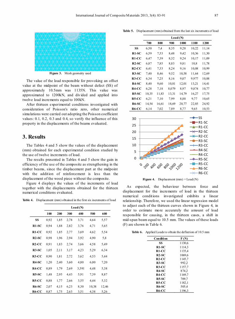
3. Results The Tables 4 and 5 show the values of the displacement
(mm) obtained for each experimental condition studied by the use of twelve increments of load.
The results presented in Tables 4 and 5 show the gain in efficiency of the use of the composite as strengthening in the timber beams, since the displacement part at the midpoint with the addit ion of reinforcement is less than the displacement of the wood piece without the composite.
Figure 4 d isplays the values of the increments of load together with the displacements obtained for the thirteen numerical conditions evaluated.
Table 4. Displacement (mm) obtained in the first six increments of load
Load (N)
100 200 300 400 500 600
SS 0,92 1,85 2,78 3,71 4,64 5,57
R1-SC 0,94 1,88 2,82 3,76 4,71 5,65
R1-CC 0,92 1,85 2,77 3,69 4,62 5,54
R2-SC 0,98 1,96 2,94 3,92 4,90 5,8
R2-CC 0,91 1,83 2,74 3,66 4,58 5,49
R3-SC 1,05 2,11 3,17 4,23 5,29 6,34
R3-CC 0,90 1,81 2,72 3,62 4,53 5,44
R4-SC 1,20 2,40 3,60 4,80 6,00 7,20
R4-CC 0,89 1,79 2,69 3,591 4,48 5,38
R5-SC 1,48 2,95 4,43 5,91 7,39 8,87
R5-CC 0,88 1,77 2,66 3,55 4,44 5,32
R6-SC 2,07 4,15 6,23 8,30 10,38 12,46 R6-CC 0,87 1,75 2,63 3,51 4,38 5,26
Table 5. Displacement (mm) obtained from the last six increments of load
Load (N) 700 800 900 1000 1100 1200
SS 6,50 7,4 8,35 9,28 10,22 11,14 R1-SC 6,59 7,53 8,48 9,42 10,36 11,30 R1-CC 6,47 7,39 8,32 9,24 10,17 11,09 R2-SC 6,87 7,85 8,83 9,81 10,8 11,78 R2-CC 6,41 7,33 8,24 9,16 10,08 10,99 R3-SC 7,40 8,46 9,52 10,58 11,64 12,69 R3-CC 6,34 7,25 8,16 9,07 9,977 10,88 R4-SC 8,40 9,60 10,81 12,01 13,21 14,41 R4-CC 6,28 7,18 8,079 8,97 9,874 10,77 R5-SC 10,35 11,83 13,31 14,79 16,27 17,75 R5-CC 6,21 7,10 7,99 8,88 9,77 10,65 R6-SC 14,54 16,61 18,69 20,77 22,85 24,92 R6-CC 6,14 7,02 7,89 8,77 9,65 10,53
Figure 4. Displacement (mm) × Load (N)
As expected, the behaviour between force and displacement for the increments of load in the thirteen numerical condit ions investigated exhibits a linear relationship. Therefore, we used the linear regression model to adjust each of the thirteen curves shown in Figure 4, in order to estimate more accurately the amount of load responsible for causing, in the thirteen cases, a shift in mid-span beam equal to 10.5 mm. The values of these loads (F) are shown in Tab le 6.
Table 6. Applied Loads to obtain the deflection of 10.5 mm
Condition F (N) SS 1130,6
R1-SC 1114,3 R1-CC 1135,4 R2-SC 1069,6 R2-CC 1145,7 R3-SC 992,2 R3-CC 1157,7 R4-SC 874,2 R4-CC 1169,7 R5-SC 709,7 R5-CC 1182,1 R6-SC 505,4 R6-CC 1196,3
0
5
10
15
20
25
30 SSR1-SCR1-CCR2-SCR2-CCR3-SCR3-CCR4-SCR4-CCR5-SCR5-CCR6-SCR6-CC
88 Júlio César Ferreira Braz et al. : Numerical Evaluation of the Mechanical Behavior of a Particulate Composite Material as Reinforcement in Timber Beams
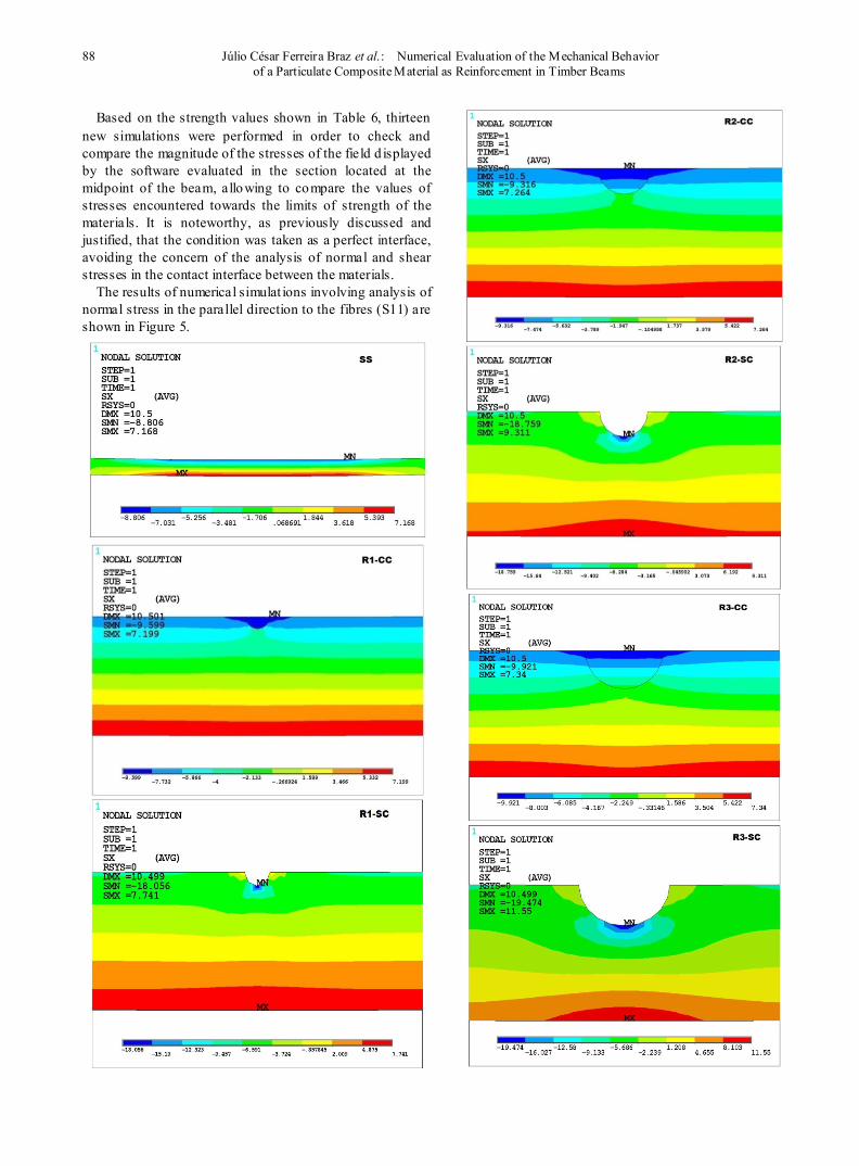
Based on the strength values shown in Table 6, thirteen new simulations were performed in order to check and compare the magnitude of the stresses of the field d isplayed by the software evaluated in the section located at the midpoint of the beam, allowing to compare the values of stresses encountered towards the limits of strength of the materials. It is noteworthy, as previously discussed and justified, that the condition was taken as a perfect interface, avoiding the concern of the analysis of normal and shear stresses in the contact interface between the materials.
The results of numerical simulat ions involving analysis of normal stress in the parallel direction to the fibres (S11) are shown in Figure 5.

International Journal of Composite Materials 2013, 3(4): 83-91 89
Figure 5. Distribution of the normal stresses
The results in the simulat ions illustrated in Figure 5 are shown in Table 7, and σC,max the maximum normal stress compression (in composites or wood) and σT,max the maximum tensile stress in the timber.
Table 7. Normal stress values of the experimental condition
Wood Composite
CE F(N) σC,max (MPa)
σT,max (MPa)
σC,max (MPa)
SS 1130,6 8,80 7,17 X R1-SC 1114,3 18,06 7,74 X R2-SC 1069,6 18,76 9,31 X R3-SC R4-SC R5-SC R6-SC
992,2 874,2 709,7 505,4
19,47 20,56 22,06 22,84
11,55 14,23 16,98 19,11
X X X X
R1-CC 1135,4 9,60 7,20 9,60 R2-CC 1145,7 9,32 7,26 9,32 R3-CC R4-CC R5-CC R6-CC
1157,7 1169,7 1182,1 1196,3
9,92 10,44 10,87 11,14
7,34 7,42 7,49 7,58
9,92 10,44 10,87 11,14
The results presented in Table 7 show that six conditions which there is only the defect on the beam and without the presence of the composite, the maximum compression stresses in the beam exceed the calculat ion value of compressive strength (fco,d) of the timber. However, the application of the composite caused a reduction of 50% in maximum compressive stress in each condition, the lower
90 Júlio César Ferreira Braz et al. : Numerical Evaluation of the Mechanical Behavior of a Particulate Composite Material as Reinforcement in Timber Beams
the calculation compressive strength of the timber, ensuring satisfactory strength to applied loads.
With the precise values of the loads responsible for causing displacements of the order of L/200 in each o f the thirteen cases assessed (Table 3) were mixed coefficient values assigned to timber Po isson ratio (0.1, 0.2, 0, 3 and 0.4). In order to verify the statistical equivalence between the displacements of the beams to the levels of Poisson's ratio was set up using the hypothesis test for equivalence between means (t-test), compared with the values of the displacements for the Poisson coefficients 0, 1, 0.2, 0.3 and 0.4 with the displacements of the beams considering zero Poisson's ratio. Tab le 8 presents the results of hypothesis testing and the interval of confidence (IC).
Table 8. Teste de hipóteses para os deslocamentos
T test IC (µ)
Teste t: 0 -0,0014 µ≤ ≤ 0,000026 0,1
Teste t: 0 -0,003057 µ≤ ≤
0,000327 0,2
Teste t: 0 -0,004772 µ≤ ≤
0,000921 0,3
Teste t: 0 -0,00687 µ≤ ≤
-0,001124 0,4
By hypothesis testing, it can be seen, with 95% confidence, not just statistical equivalence among Poisson regression coefficients 0 and 0.4 for the irrelevance of zero in the confidence interval (μ), being equivalent to the other cases, be presenting minor the influence of Po isson's ratio.
4. Conclusions By analysing the values found for the maximum tensile e
compressive stresses acting on the wood and the compressive stresses acting on composite, concluded that the beams safely resist the action of loads applied by the use of the composite.
The evaluation of Po isson's ratio, the result of consideration of isotropy of the wood revealed the non-equivalence between the displacement values only between 0 and 0.4, being equivalent to the others, claiming not to be a significant consideration, hypothesis usually assumed in practice by building professionals since the Brazilian standard ABNT NBR 7190:1197 [15] does not provide informat ion regard ing the anisotropic mechanical properties of wood species.
The strategy of using the ceramic-polymer composite compressed region of the timber beams appeared as a promising alternative as reinforcement, avoiding the previous study of the interface conditions between materials to small indentations, since the set was designed for small displacements and the composite confined in wood.
The use of the composite in semicircu lar cavity radius of 60mm proved to be the most interesting solution for the beam studied, since it has the largest area of contact between the materials (most of the radius studied), reducing the value of the maximum shear stress in the interface reg ion and allowing the use of a load of around 5.8% higher than the load applied to the reference beam without defect. Recall that the neutral line, found to fifty millimetres from the upper face, is overcome in the radius of 60mm.
REFERENCES [1] Christoforo, A. L.; Panzera, T. H.; Brito, J. N.; Lamim Filho,
P. C. M.; Brandão, L. C. Avaliação numérica do emprego de uma blenda cerâmica polimérica como reforço em vigas de madeira. Anais do XI Congresso Nacional de Engenharia Mecânica, Metalúrgica e industrial. Porto Alegre (RS), 2011.
[2] Calil, C. Jr.; Lahr, F. A. R.; Dias, A. A. Dimensionamento de elementos estruturais de madeira. Barueri – SP: Manole Ltda, ISBN: 85-204-1515-6, 2003.
[3] Christoforo, A. L.; Zangiácomo, A. L.; Panzera, T. H.; Silveira, M. E. ; Rocco, F. A. L. Emprego de Ferramentas Numéricas na Avaliação do Módulo de Elasticidade em Vigas Roliças de Madeira. Engenharia Agrícola (Online), v. 32, p. 971-980, 2012.
[4] Balseiro, A.; Negrão, J.; Faria, J. A. Reforço de vigas de madeira com laminados de carbono pré-esforçados. Construlink.com - Tecnologias de Informação, S.A., no16, v. 6., p. 14-24, ISSN 1645-5576, Lisboa (PT), 2008.
[5] Miotto, J. L; Dias, A. A. Reforço e recuperação de estruturas de madeira. Revista Semanal: Ciências Exatas e Tecnológicas, Londrina, v. 27, n. 2, p. 163-174, 2006.
[6] Fiorelli, J. Analysis of the Strength and Stiffness of Timber Beams Reinforced with Carbon Fiber and Glass Fiber. v. 6, n. 2. P. 193-202, 2003.
[7] Fiorelli, J. Utilização de fibras de carbono e de fibras de vidro para reforço de vigas de madeira. Dissertação (Mestrado) - Faculdade de Engenharia de São Carlos, Universidade de São Paulo, São Carlos – SP. p. 202- 214, 2002.
[8] Mettem, C. J.; Robinson, G. C. The repair of structural timber. IN: International timber engineering conference, London. London, p.4.56-4.65, 1991.
[9] Carvalho, S. S.; Dutra, J. R.; Carvalho, A. L. C.; Vieira, L. M. G.; Christoforo, A. L. Experimental evaluation of the employment of a laminated composite material with sisal fibres as reinforcement in timber beams. International Journal of Composite Material, v. 2, p. 97-100, 2012.
[10] Ritter, Michael A. Timber bridges: design construction, inspection, and maintenance. Washington, DC. 944p., 1990.
[11] Campilho, R. D. S. G; Benea M. D.; Pinto, A. M. Reparação de vigas de madeira com laminados de compósitos de carbono-epóxido. Encontro Nacional de Materiais e Estruturas Compósitas (ENMEC), Porto-Portugal (PT): Anais em CD-ROM, 2010.
International Journal of Composite Materials 2013, 3(4): 83-91 91
[12] Borri, A.; Corradi, M.; Grazini, A. A method for flexural reinforcement of old wood beams with CFRP materials, Composites: Part B. v. 36, p. 143-153, 2005.
[13] Jankowski, L. J.; Jasieñko, J.; Nowak, T. P. Experimental assessment of CFRP reinforced wooden beams by 4-point bending tests and photoelastic coating technique. v. 43. Materials and Structures, p. 141-150, 2010.
[14] Panzera, T. H.; Sabariz, A. L. R.; Strecker, K.; Borges, P. H. R.; Vasconcelos, D. C. L.; Wasconcelos, W. L. Propriedades mecânicas de materiais compósitos à base de cimento portland e resina epoxi. Cerâmica 56, p. 77-82, 2010.
[15] Associação Brasileira de Normas Técnicas (ABNT) NBR7190 - Projeto de estruturas de madeira. Rio de Janeiro: ABNT, 1997.
[16] Van Gemert, D.; Czarnecki, L.; Maultzsch, M.; Schorn, H.; Beeldens, A.; Lukowski, P.; Knapen, E. Cement concrete and concrete–polymer composites: Two merging worlds. A report from 11th ICPIC Congress in Berlin, 2004.
[17] Rai, U. S.; Singh R. K. Synthesis and mechanical characterization of polymer-matrix composites containing
calcium carbonate/white cement filler. Materials Letters, v. 58, p. 235– 240. 2003.
[18] Silva, D. A.; Monteiro, P. J. M. The influence of polymers on the hydration of portland cement phases analyzed by soft X-ray transmission microscopy. v. 36, Cement and Concrete Research, p. 1501–1507, 2006.
[19] Ohama, Y. Recent Progress in Concrete-Polymer Composites. Adv. Cem. Bas. Mater. v.1, 5 ed.. 1997.
[20] Daniel, I. M.; Ishai, O. Engineering mechanics of composite materials. New York: Oxford University Press, 1994.
[21] American Society for Testing and Materials (ASTM) ASTM D198–97. Static tests of timbers in structural sizes. Philadelphia, PA, 1976.
[22] Rocco Lahr, F. A. R. Sobre a determinação de propriedades de elasticidade da madeira. 216p. Tese de Doutorado. Escola de Engenharia de São Carlos, Universidade de São Paulo, São Carlos – SP, 1983.