Numerical Circuit Breaker Failure · PDF file7SV512 V1.0 Instruction Manual Numerical Circuit...
136
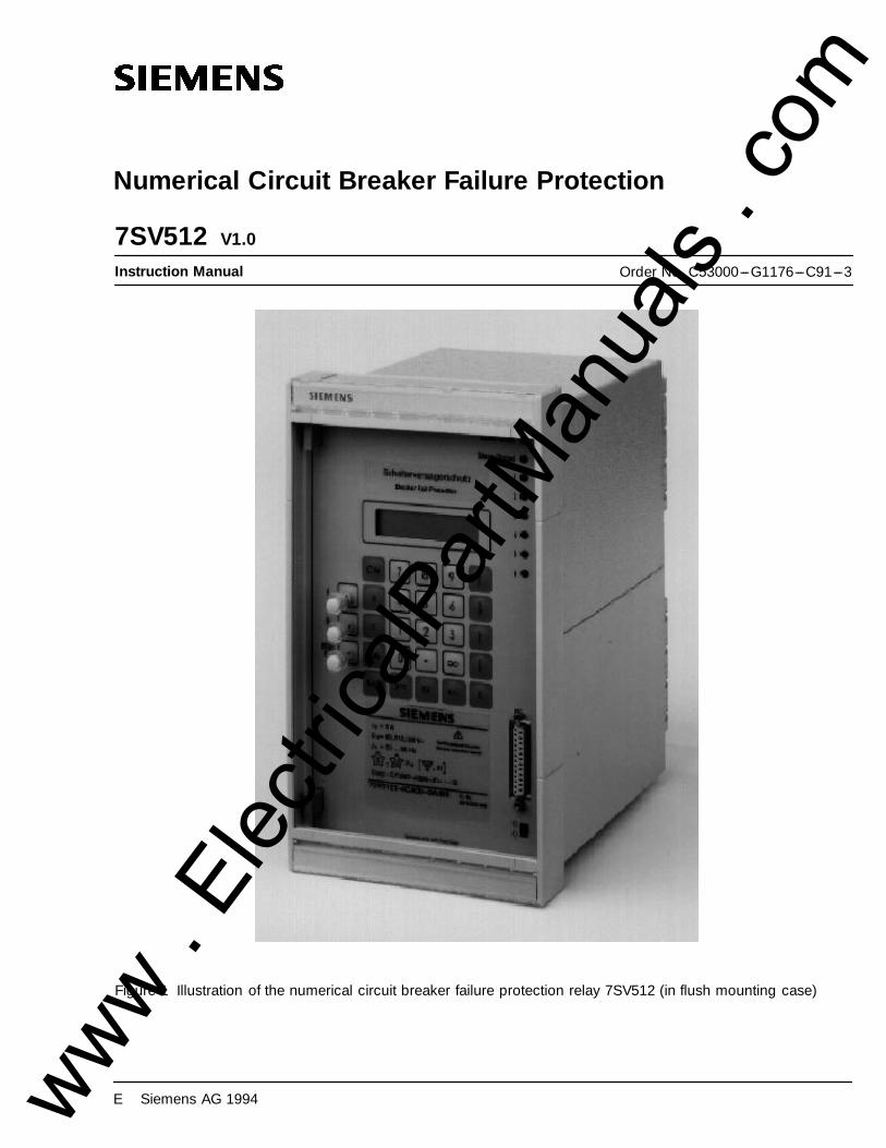
7SV512 V1.0 Instruction Manual Numerical Circuit Breaker Failure Protection Order No. C53000---G1176---C91---3 Figure 1 Illustration of the numerical circuit breaker failure protection relay 7SV512 (in flush mounting case) E Siemens AG 1994 www . ElectricalPartManuals . com
-
Upload
nguyenthien -
Category
Documents
-
view
234 -
download
3
Transcript of Numerical Circuit Breaker Failure · PDF file7SV512 V1.0 Instruction Manual Numerical Circuit...
7SV512 V1.0
Instruction Manual
Numerical Circuit Breaker Failure Protection
Order No. C53000---G1176---C91---3
Figure 1 Illustration of the numerical circuit breaker failure protection relay 7SV512 (in flush mounting case)
E Siemens AG 1994www . El
ectric
alPar
tMan
uals
. com

www . El
ectric
alPar
tMan
uals
. com

Conformity7SV512 V1
iiiC53000---G1176---C91
Conformity
This product is in conformity with the directive of the Council of the European Communities on the approxima-tion of the laws of the Member States relating to electromagnetic compatibility (EMC Council Directive89/336/EEC) and concerning electrical equipment for application within specified voltage limits (Low-voltagedirective 73/23 EEC).
Conformity is proved by tests that had been performed according to article 10 of the Council Directive in accor-dance with the generic standards EN 50081---2 and EN 50082---2 (for EMC directive) and the standards EN60255---6 (for low-voltage directive) by Siemens AG by Siemens AG.
The device is designed and manufactured for application in industrial environment.
The device is designed in accordance with the international standards of IEC 60255 and the German stan-dards DIN 57435 part 303 (corresponding to VDE 0435 part 303).
www . El
ectric
alPar
tMan
uals
. com

Conformity7SV512 V1
C53000---G1176---C91iv
This page intentionally left blank.
www . El
ectric
alPar
tMan
uals
. com
7SV512 ContentsV1
vC53000---G1176---C91
Contents
1 Introduction 9. . . . . . . . . . . . . . . . . . . . . . . . . . . . . . . . . . . . . . . . . . . . . . . . . . . . . . . . . . . . . . . . . . . . . . .
1.1 Application 9. . . . . . . . . . . . . . . . . . . . . . . . . . . . . . . . . . . . . . . . . . . . . . . . . . . . . . . . . . . . . . . . . . . . . . . . . .
1.2 Features 10. . . . . . . . . . . . . . . . . . . . . . . . . . . . . . . . . . . . . . . . . . . . . . . . . . . . . . . . . . . . . . . . . . . . . . . . . . .
2 Design 11. . . . . . . . . . . . . . . . . . . . . . . . . . . . . . . . . . . . . . . . . . . . . . . . . . . . . . . . . . . . . . . . . . . . . . . . . . . .
2.1 Arrangements 11. . . . . . . . . . . . . . . . . . . . . . . . . . . . . . . . . . . . . . . . . . . . . . . . . . . . . . . . . . . . . . . . . . . . . .
2.2 Dimensions 13. . . . . . . . . . . . . . . . . . . . . . . . . . . . . . . . . . . . . . . . . . . . . . . . . . . . . . . . . . . . . . . . . . . . . . . .
2.3 Ordering data 15. . . . . . . . . . . . . . . . . . . . . . . . . . . . . . . . . . . . . . . . . . . . . . . . . . . . . . . . . . . . . . . . . . . . . .
3 Technical Data 16. . . . . . . . . . . . . . . . . . . . . . . . . . . . . . . . . . . . . . . . . . . . . . . . . . . . . . . . . . . . . . . . . . .
3.1 General data 16. . . . . . . . . . . . . . . . . . . . . . . . . . . . . . . . . . . . . . . . . . . . . . . . . . . . . . . . . . . . . . . . . . . . . . .3.1.1 Inputs/outputs 16. . . . . . . . . . . . . . . . . . . . . . . . . . . . . . . . . . . . . . . . . . . . . . . . . . . . . . . . . . . . . . . . . . . . . . .3.1.2 Electrical tests 18. . . . . . . . . . . . . . . . . . . . . . . . . . . . . . . . . . . . . . . . . . . . . . . . . . . . . . . . . . . . . . . . . . . . . . .3.1.3 Mechanical stress tests 19. . . . . . . . . . . . . . . . . . . . . . . . . . . . . . . . . . . . . . . . . . . . . . . . . . . . . . . . . . . . . . .3.1.4 Climatic stress tests 20. . . . . . . . . . . . . . . . . . . . . . . . . . . . . . . . . . . . . . . . . . . . . . . . . . . . . . . . . . . . . . . . . .3.1.5 Service conditions 20. . . . . . . . . . . . . . . . . . . . . . . . . . . . . . . . . . . . . . . . . . . . . . . . . . . . . . . . . . . . . . . . . . .3.1.6 Design 20. . . . . . . . . . . . . . . . . . . . . . . . . . . . . . . . . . . . . . . . . . . . . . . . . . . . . . . . . . . . . . . . . . . . . . . . . . . . .
3.2 Circuit breaker failure protection 21. . . . . . . . . . . . . . . . . . . . . . . . . . . . . . . . . . . . . . . . . . . . . . . . . . . . .
3.3 Circuit breaker pole discrepancy supervision 21. . . . . . . . . . . . . . . . . . . . . . . . . . . . . . . . . . . . . . . . .
3.4 Ancillary functions 22. . . . . . . . . . . . . . . . . . . . . . . . . . . . . . . . . . . . . . . . . . . . . . . . . . . . . . . . . . . . . . . . . .
4 Method of operation 23. . . . . . . . . . . . . . . . . . . . . . . . . . . . . . . . . . . . . . . . . . . . . . . . . . . . . . . . . . . . .
4.1 Operation of complete unit 23. . . . . . . . . . . . . . . . . . . . . . . . . . . . . . . . . . . . . . . . . . . . . . . . . . . . . . . . . .
4.2 Circuit breaker failure protection 25. . . . . . . . . . . . . . . . . . . . . . . . . . . . . . . . . . . . . . . . . . . . . . . . . . . . .4.2.1 General 25. . . . . . . . . . . . . . . . . . . . . . . . . . . . . . . . . . . . . . . . . . . . . . . . . . . . . . . . . . . . . . . . . . . . . . . . . . . . .4.2.2 Current flow monitoring 26. . . . . . . . . . . . . . . . . . . . . . . . . . . . . . . . . . . . . . . . . . . . . . . . . . . . . . . . . . . . . . .4.2.3 Processing of the circuit breaker auxiliary contacts 27. . . . . . . . . . . . . . . . . . . . . . . . . . . . . . . . . . . . . . .4.2.4 Initiation conditions and delay times 29. . . . . . . . . . . . . . . . . . . . . . . . . . . . . . . . . . . . . . . . . . . . . . . . . . . .4.2.4.1 Common phase initiation 29. . . . . . . . . . . . . . . . . . . . . . . . . . . . . . . . . . . . . . . . . . . . . . . . . . . . . . . . . . . . .4.2.4.2 Two-stage breaker failure protection with common phase initiation 30. . . . . . . . . . . . . . . . . . . . . . . . .4.2.4.3 Phase segregated initiation 30. . . . . . . . . . . . . . . . . . . . . . . . . . . . . . . . . . . . . . . . . . . . . . . . . . . . . . . . . . .4.2.4.4 Combined initiation conditions 33. . . . . . . . . . . . . . . . . . . . . . . . . . . . . . . . . . . . . . . . . . . . . . . . . . . . . . . .4.2.4.5 Function examples 33. . . . . . . . . . . . . . . . . . . . . . . . . . . . . . . . . . . . . . . . . . . . . . . . . . . . . . . . . . . . . . . . . . .4.2.5 Circuit breaker not fully operational 34. . . . . . . . . . . . . . . . . . . . . . . . . . . . . . . . . . . . . . . . . . . . . . . . . . . .4.2.6 Transfer trip to the remote end circuit breaker 34. . . . . . . . . . . . . . . . . . . . . . . . . . . . . . . . . . . . . . . . . . .4.2.7 Hardware supervision and blocking 34. . . . . . . . . . . . . . . . . . . . . . . . . . . . . . . . . . . . . . . . . . . . . . . . . . . .
4.3 End fault protection 36. . . . . . . . . . . . . . . . . . . . . . . . . . . . . . . . . . . . . . . . . . . . . . . . . . . . . . . . . . . . . . . . .
4.4 Circuit breaker pole discrepancy supervision 36. . . . . . . . . . . . . . . . . . . . . . . . . . . . . . . . . . . . . . . . .
4.5 Ancillary functions 37. . . . . . . . . . . . . . . . . . . . . . . . . . . . . . . . . . . . . . . . . . . . . . . . . . . . . . . . . . . . . . . . . .4.5.1 Processing of annunciations 37. . . . . . . . . . . . . . . . . . . . . . . . . . . . . . . . . . . . . . . . . . . . . . . . . . . . . . . . . .4.5.1.1 Indicators and binary outputs (signal relays) 37. . . . . . . . . . . . . . . . . . . . . . . . . . . . . . . . . . . . . . . . . . . .4.5.1.2 Information on the display panel or to a personal computer 37. . . . . . . . . . . . . . . . . . . . . . . . . . . . . . .4.5.1.3 Information to a central unit (optional) 38. . . . . . . . . . . . . . . . . . . . . . . . . . . . . . . . . . . . . . . . . . . . . . . . . .4.5.2 Data storage and transmission for fault recording 38. . . . . . . . . . . . . . . . . . . . . . . . . . . . . . . . . . . . . . . .4.5.3 Operating measurements and conversion 38. . . . . . . . . . . . . . . . . . . . . . . . . . . . . . . . . . . . . . . . . . . . . .www .
Elec
tricalP
artM
anua
ls . c
om
Contents7SV512 V1
C53000---G1176---C91vi
4.5.4 Monitoring functions 39. . . . . . . . . . . . . . . . . . . . . . . . . . . . . . . . . . . . . . . . . . . . . . . . . . . . . . . . . . . . . . . . .4.5.4.1 Hardware monitoring 39. . . . . . . . . . . . . . . . . . . . . . . . . . . . . . . . . . . . . . . . . . . . . . . . . . . . . . . . . . . . . . . . .4.5.4.2 Software monitoring 40. . . . . . . . . . . . . . . . . . . . . . . . . . . . . . . . . . . . . . . . . . . . . . . . . . . . . . . . . . . . . . . . . .4.5.4.3 Monitoring of external measuring transformer circuits 40. . . . . . . . . . . . . . . . . . . . . . . . . . . . . . . . . . . .
5 Installation instructions 41. . . . . . . . . . . . . . . . . . . . . . . . . . . . . . . . . . . . . . . . . . . . . . . . . . . . . . . . .
5.1 Unpacking and repacking 41. . . . . . . . . . . . . . . . . . . . . . . . . . . . . . . . . . . . . . . . . . . . . . . . . . . . . . . . . . .
5.2 Preparations 41. . . . . . . . . . . . . . . . . . . . . . . . . . . . . . . . . . . . . . . . . . . . . . . . . . . . . . . . . . . . . . . . . . . . . . .5.2.1 Mounting and connections 42. . . . . . . . . . . . . . . . . . . . . . . . . . . . . . . . . . . . . . . . . . . . . . . . . . . . . . . . . . . .5.2.1.1 Model 7SV512K---KBKKK for panel surface mounting 42. . . . . . . . . . . . . . . . . . . . . . . . . . . . . . . . . . . . .5.2.1.2 Model 7SV512K---KCKKK for panel flush mounting or cubicle installation 42. . . . . . . . . . . . . . . . . . . .5.2.2 Checking the rated data 42. . . . . . . . . . . . . . . . . . . . . . . . . . . . . . . . . . . . . . . . . . . . . . . . . . . . . . . . . . . . . .5.2.2.1 Control d.c. voltage of binary inputs 42. . . . . . . . . . . . . . . . . . . . . . . . . . . . . . . . . . . . . . . . . . . . . . . . . . . .5.2.3 Checking the LSA data transmission link 44. . . . . . . . . . . . . . . . . . . . . . . . . . . . . . . . . . . . . . . . . . . . . . .5.2.4 Connections 45. . . . . . . . . . . . . . . . . . . . . . . . . . . . . . . . . . . . . . . . . . . . . . . . . . . . . . . . . . . . . . . . . . . . . . . .5.2.5 Checking the connections 47. . . . . . . . . . . . . . . . . . . . . . . . . . . . . . . . . . . . . . . . . . . . . . . . . . . . . . . . . . . .
5.3 Configuration of operational functions 48. . . . . . . . . . . . . . . . . . . . . . . . . . . . . . . . . . . . . . . . . . . . . . .5.3.1 Operational preconditions 48. . . . . . . . . . . . . . . . . . . . . . . . . . . . . . . . . . . . . . . . . . . . . . . . . . . . . . . . . . . .5.3.2 Settings for operating parameters --- address block 70 48. . . . . . . . . . . . . . . . . . . . . . . . . . . . . . . . . . .
5.4 Configuration of the device functions 51. . . . . . . . . . . . . . . . . . . . . . . . . . . . . . . . . . . . . . . . . . . . . . . .5.4.1 Introduction 51. . . . . . . . . . . . . . . . . . . . . . . . . . . . . . . . . . . . . . . . . . . . . . . . . . . . . . . . . . . . . . . . . . . . . . . . .5.4.2 Programming the scope of functions --- address block 78 52. . . . . . . . . . . . . . . . . . . . . . . . . . . . . . . . .
5.5 Marshalling of binary inputs, binary outputs and LED indicators 53. . . . . . . . . . . . . . . . . . . . . . .5.5.1 Introduction 53. . . . . . . . . . . . . . . . . . . . . . . . . . . . . . . . . . . . . . . . . . . . . . . . . . . . . . . . . . . . . . . . . . . . . . . . .5.5.2 Marshalling of the binary inputs --- address block 61 55. . . . . . . . . . . . . . . . . . . . . . . . . . . . . . . . . . . . .5.5.3 Marshalling of the signal output relays --- address block 62 58. . . . . . . . . . . . . . . . . . . . . . . . . . . . . . .5.5.4 Marshalling of the LED indicators --- address block 63 61. . . . . . . . . . . . . . . . . . . . . . . . . . . . . . . . . . . .5.5.5 Marshalling of the command (trip) relays --- address block 64 63. . . . . . . . . . . . . . . . . . . . . . . . . . . . .
5.6 Configuration parameters for localized substation automation --- address block 69 65. . . . . .
6 Operating instructions 67. . . . . . . . . . . . . . . . . . . . . . . . . . . . . . . . . . . . . . . . . . . . . . . . . . . . . . . . . .
6.1 Safety precautions 67. . . . . . . . . . . . . . . . . . . . . . . . . . . . . . . . . . . . . . . . . . . . . . . . . . . . . . . . . . . . . . . . . .
6.2 Dialog with the relay 67. . . . . . . . . . . . . . . . . . . . . . . . . . . . . . . . . . . . . . . . . . . . . . . . . . . . . . . . . . . . . . . .6.2.1 Membrane keyboard and display panel 67. . . . . . . . . . . . . . . . . . . . . . . . . . . . . . . . . . . . . . . . . . . . . . . .6.2.2 Operation with a personal computer 68. . . . . . . . . . . . . . . . . . . . . . . . . . . . . . . . . . . . . . . . . . . . . . . . . . .6.2.3 Operational preconditions 68. . . . . . . . . . . . . . . . . . . . . . . . . . . . . . . . . . . . . . . . . . . . . . . . . . . . . . . . . . . .6.2.4 Representation of the relay (front view) 69. . . . . . . . . . . . . . . . . . . . . . . . . . . . . . . . . . . . . . . . . . . . . . . . .
6.3 Setting the functional parameters 70. . . . . . . . . . . . . . . . . . . . . . . . . . . . . . . . . . . . . . . . . . . . . . . . . . . .6.3.1 Introduction 70. . . . . . . . . . . . . . . . . . . . . . . . . . . . . . . . . . . . . . . . . . . . . . . . . . . . . . . . . . . . . . . . . . . . . . . . .6.3.1.1 Parameterizing procedure 70. . . . . . . . . . . . . . . . . . . . . . . . . . . . . . . . . . . . . . . . . . . . . . . . . . . . . . . . . . . .6.3.1.2 Selectable parameter sets 71. . . . . . . . . . . . . . . . . . . . . . . . . . . . . . . . . . . . . . . . . . . . . . . . . . . . . . . . . . . .6.3.1.3 Setting of date and time 72. . . . . . . . . . . . . . . . . . . . . . . . . . . . . . . . . . . . . . . . . . . . . . . . . . . . . . . . . . . . . .6.3.2 Initial displays --- address blocks 00 and 10 73. . . . . . . . . . . . . . . . . . . . . . . . . . . . . . . . . . . . . . . . . . . . .6.3.3 Power system data --- address block 11 73. . . . . . . . . . . . . . . . . . . . . . . . . . . . . . . . . . . . . . . . . . . . . . . .6.3.4 Settings for circuit breaker failure protection --- address block 12 75. . . . . . . . . . . . . . . . . . . . . . . . . .6.3.5 Settings for fault recording --- address block 28 80. . . . . . . . . . . . . . . . . . . . . . . . . . . . . . . . . . . . . . . . . .6.3.6 Settings for measured value monitoring --- address block 29 81. . . . . . . . . . . . . . . . . . . . . . . . . . . . . .6.3.7 Settings for breaker pole discrepancy supervision --- address block 38 82. . . . . . . . . . . . . . . . . . . . .
6.4 Annunciations 83. . . . . . . . . . . . . . . . . . . . . . . . . . . . . . . . . . . . . . . . . . . . . . . . . . . . . . . . . . . . . . . . . . . . . .6.4.1 Introduction 83. . . . . . . . . . . . . . . . . . . . . . . . . . . . . . . . . . . . . . . . . . . . . . . . . . . . . . . . . . . . . . . . . . . . . . . . .6.4.2 Operational annunciations --- address block 51 84. . . . . . . . . . . . . . . . . . . . . . . . . . . . . . . . . . . . . . . . . .6.4.3 Fault annunciations --- address block 52 to 54 88. . . . . . . . . . . . . . . . . . . . . . . . . . . . . . . . . . . . . . . . . . .6.4.4 Circuit breaker operation statistics --- address block 56 91. . . . . . . . . . . . . . . . . . . . . . . . . . . . . . . . . . .6.4.5 Read-out of operational measured values --- address block 57 92. . . . . . . . . . . . . . . . . . . . . . . . . . . .www .
Elec
tricalP
artM
anua
ls . c
om
7SV512 ContentsV1
viiC53000---G1176---C91
6.5 Operational control facilities 93. . . . . . . . . . . . . . . . . . . . . . . . . . . . . . . . . . . . . . . . . . . . . . . . . . . . . . . . .6.5.1 Adjusting and synchronizing the real time clock --- address block 81 93. . . . . . . . . . . . . . . . . . . . . . .6.5.2 Erasing stored annunciations and counters --- address block 82 94. . . . . . . . . . . . . . . . . . . . . . . . . . .6.5.3 Off/On control of part functions of the device 95. . . . . . . . . . . . . . . . . . . . . . . . . . . . . . . . . . . . . . . . . . . .6.5.4 Selection of parameter sets --- address block 85 97. . . . . . . . . . . . . . . . . . . . . . . . . . . . . . . . . . . . . . . . .6.5.4.1 Read-out of settings of a parameter set 97. . . . . . . . . . . . . . . . . . . . . . . . . . . . . . . . . . . . . . . . . . . . . . . . .6.5.4.2 Change-over of the active parameter set from the operating panel 97. . . . . . . . . . . . . . . . . . . . . . . . .6.5.4.3 Change-over of the active parameter set via binary inputs 98. . . . . . . . . . . . . . . . . . . . . . . . . . . . . . . .
6.6 Testing and commissioning 99. . . . . . . . . . . . . . . . . . . . . . . . . . . . . . . . . . . . . . . . . . . . . . . . . . . . . . . . . .6.6.1 General 99. . . . . . . . . . . . . . . . . . . . . . . . . . . . . . . . . . . . . . . . . . . . . . . . . . . . . . . . . . . . . . . . . . . . . . . . . . . . .6.6.2 Testing the circuit breaker failure protection 100. . . . . . . . . . . . . . . . . . . . . . . . . . . . . . . . . . . . . . . . . . . .6.6.3 Testing the end fault protection 101. . . . . . . . . . . . . . . . . . . . . . . . . . . . . . . . . . . . . . . . . . . . . . . . . . . . . . .6.6.4 Testing the circuit breaker pole discrepancy supervision 101. . . . . . . . . . . . . . . . . . . . . . . . . . . . . . . . .
6.7 Commissioning using primary tests 102. . . . . . . . . . . . . . . . . . . . . . . . . . . . . . . . . . . . . . . . . . . . . . . . .6.7.1 Checking the initiation conditions 102. . . . . . . . . . . . . . . . . . . . . . . . . . . . . . . . . . . . . . . . . . . . . . . . . . . . .6.7.2 Checking the local trip with breaker failure criterion from the auxiliary contacts 103. . . . . . . . . . . . .6.7.3 Checking the local trip and the current circuits 103. . . . . . . . . . . . . . . . . . . . . . . . . . . . . . . . . . . . . . . . .6.7.4 Checking the intertrip to the opposite feeder end 104. . . . . . . . . . . . . . . . . . . . . . . . . . . . . . . . . . . . . . .6.7.4 Checking the bus-bar trip 104. . . . . . . . . . . . . . . . . . . . . . . . . . . . . . . . . . . . . . . . . . . . . . . . . . . . . . . . . . . .
6.8 Putting the relay into operation 105. . . . . . . . . . . . . . . . . . . . . . . . . . . . . . . . . . . . . . . . . . . . . . . . . . . . .
7 Maintenance and fault tracing 106. . . . . . . . . . . . . . . . . . . . . . . . . . . . . . . . . . . . . . . . . . . . . . . .
7.1 Routine checks 106. . . . . . . . . . . . . . . . . . . . . . . . . . . . . . . . . . . . . . . . . . . . . . . . . . . . . . . . . . . . . . . . . . . .7.2 Replacing the clock module 107. . . . . . . . . . . . . . . . . . . . . . . . . . . . . . . . . . . . . . . . . . . . . . . . . . . . . . . .7.3 Fault tracing 108. . . . . . . . . . . . . . . . . . . . . . . . . . . . . . . . . . . . . . . . . . . . . . . . . . . . . . . . . . . . . . . . . . . . . . .7.3.1 Replacing the mini-fuse 109. . . . . . . . . . . . . . . . . . . . . . . . . . . . . . . . . . . . . . . . . . . . . . . . . . . . . . . . . . . . . .
8 Repairs 111. . . . . . . . . . . . . . . . . . . . . . . . . . . . . . . . . . . . . . . . . . . . . . . . . . . . . . . . . . . . . . . . . . . . . . . . .
9 Storage 111. . . . . . . . . . . . . . . . . . . . . . . . . . . . . . . . . . . . . . . . . . . . . . . . . . . . . . . . . . . . . . . . . . . . . . . . .
Appendix 112. . . . . . . . . . . . . . . . . . . . . . . . . . . . . . . . . . . . . . . . . . . . . . . . . . . . . . . . . . . . . . . . . . . . . . . . . .
A General diagrams 113. . . . . . . . . . . . . . . . . . . . . . . . . . . . . . . . . . . . . . . . . . . . . . . . . . . . . . . . . . . . . . . . . .B Connection diagrams 116. . . . . . . . . . . . . . . . . . . . . . . . . . . . . . . . . . . . . . . . . . . . . . . . . . . . . . . . . . . . . .C Tables 119. . . . . . . . . . . . . . . . . . . . . . . . . . . . . . . . . . . . . . . . . . . . . . . . . . . . . . . . . . . . . . . . . . . . . . . . . . .
NOTE:
This instruction manual does not purport to cover alldetails in equipment, nor to provide for every possi-ble contingency to be met in connection with instal-lation, operation or maintenance.
Should further information be desired or should par-ticular problems arise which are not covered suffi-ciently for the purchaser’s purpose, the mattershould be referred to the local Siemens sales office.
The contents of this instruction manual shall not be-come part nor modify any prior or existing agree-ment, commitment or relationship. The sales con-tract contains the entire obligations of Siemens. Thewarranty contained in the contract between the par-ties is the sole warranty of Siemens. Any statementscontained herein do not create new warranties normodify the existing warranty.www .
Elec
tricalP
artM
anua
ls . c
om

Contents7SV512 V1
C53000---G1176---C91viii
This page intentionally left blank.
www . El
ectric
alPar
tMan
uals
. com

Introduction7SV512 V1
9C53000---G1176---C91
1 Introduction
1.1 Application
The numerical circuit breaker failure protection relay7SV512 provides rapid back-up fault clearance in-struction to the associated circuit breakers in casethe circuit breaker nearest to the fault fails to re-spond.
It is suitable for power systems of all voltage ranges.The initiation signal can be derived from any protec-tion or supervision equipment or, in case of manualopening, from the discrepancy control switch of thebreaker. Information from the circuit breaker auxilia-ry contact(s) is required for the breaker failure pro-tection to function during faults which produce littleor no current flow (e.g. Buchholz protection).
The breaker failure protection can operate single-stage or two-stage. When used as single-stage pro-tection, the bus trip command is given to the adja-cent circuit breakers if the protected feeder breakerfails. When used as two-stage protection, the firststage can be used to repeat the trip command to therelevant breaker, normally on different trip coils, if theinitial trip command from the feeder protection is notexecuted. The second stage will result in a bus trip tothe adjacent breakers, if the command of the firststage is not successful.
The bus trip command from the breaker failure pro-tection can be routed to all circuit breakers linked tothe same bus-bar (section) as the breaker thatfailed. It can also be transmitted to the remote endby means of a suitable communication link (e.g.PLC, radio wave, or optical fibre). The distributionlogic which is necessary in case of multiple bus-barsections is not part of 7SV512 relay.
The current level is monitored in each of the threephases against a set threshold. In addition, the re-sidual earth current is monitored or --- if this is notavailable --- the negative sequence component ofthe phase currents derived by symmetrical compo-nent analysis. This ensures high security againstmalfunction by use of a 2-out-of-4 check of the cur-rent detectors.
Phase segregated current monitoring enables reli-able breaker failure detection even during single-pole auto-reclose cycles provided the phase segre-gated trip signals of the feeder protection are con-nected to 7SV512. If two-stage breaker failure pro-tection is used in conjunction with single-pole trip-ping by the feeder protection, the first stage trip may
be performed single-pole or three-pole, as selectedby the user. Different delay times can be set forsingle-phase faults and multi-phase faults.
If the protected circuit breaker is not operative (e.g.air pressure failure), instantaneous bus trip of theadjacent circuit breakers can be achieved followinga feeder protection trip provided the relay is in-formed by an external breaker monitor.
An end fault protection function is integrated in the7SV512 relay. An end fault is a short-circuit locatedbetween the circuit breaker and the current trans-former set of the feeder. For this fault current flow isdetected although the auxiliary contacts of thebreaker indicate open breaker pole(s). A commandsignal is generated which can be transmitted to theremote end breaker.
A circuit breaker pole discrepancy supervision is in-tegrated in the 7SV512. It prevents that only one ortwo poles of the breaker are open continuously. Athree-pole trip is initiated when pole discrepancy isdetected for a set time.
Special measures are taken to prevent malfunctionof the relay. Besides the mentioned 2-out-of-4 checkof the current detection elements the trip signals ofthe feeder protection must be connected in redun-dant manner so that they can be checked for plausi-bility. An additional hard-ware monitor ensures mul-ti-channel control of the trip relays. Continuous mon-itoring of the measured values permits rapid annun-ciation of any fault in the measuring transformer cir-cuits. Continuous plausibility monitoring of the inter-nal measured value processing circuits and moni-toring of the auxiliary voltages to ensure that they re-main within tolerance are obviously inherent fea-tures.
Throughout a fault in the network the magnitudes ofthe instantaneous values are stored for a period ofmax. 3 seconds (0.66 seconds at 50 Hz for trans-mission to a central computer station) and are avail-able for subsequent fault analysis.
Serial interfaces allow comprehensive communica-tion with other digital control and storage devices.For data transmission a standardized protocol in ac-cordance with DIN 19244 is used. The device cantherefore be incorporated in Localized SubstationAutomation networks (LSA).www .
Elec
tricalP
artM
anua
ls . c
om

Introduction7SV512 V1
C53000---G1176---C9110
1.2 Features
--- Processor system with powerful 16---bit---micro-processor;
--- Complete digital measured value processing andcontrol from data acquisition and digitizing of themeasured values up to the trip decisions for thecircuit breakers;
--- Complete galvanic and reliable separation of theinternal processing circuits from the measure-ment, control and supply circuits of the system,with screened analog input transducers, binaryinput and output modules and DC converter;
--- Highly sensitive current detection;
--- Independent current detectors for monitoring ofcurrent flow through each individual circuit break-er pole;
--- 2-out-of-4 check of the current detectors;
--- Short reset time, negligible overshoot time;
--- Independent delay times for each circuit breakerpole;
--- Single-stage or two-stage delay;
--- Can be controlled from circuit breaker auxiliarycontacts; if single-pole control is used, the individ-ual auxiliary contacts of each pole, or series andparallel connection of the auxiliary contacts canbe connected;
--- Can be initiated by single-pole or three-pole tripcommands;
--- Can be initiated by different protection relays,even single-pole or three-pole or both;
--- Instantaneous trip possible in case of defectivecircuit breaker;
--- Transmission of trip command to the remote endpossible;
--- Integrated end fault protection for intertrip;
--- Integrated circuit breaker pole discrepancy su-pervision;
--- Calculation of operational measured values andindication on the front display;
--- Simple setting and operation using the integratedoperation panel or a connected personal comput-er with menu-guided software;
--- Communication with central control and storagedevices via serial interfaces is possible by meansof optical fibre;
--- Annunciation storage of the last three networkfaults, with optional real time clock;
--- Data storage and transmission for fault recordsgivingrapid fault analysis,detailed fault records;
--- Counting of tripping commands as well as record-ing of fault data and accumulative addition of theinterrupted fault currents;
--- Continuous self-monitoring right from the d.c. cir-cuits, through the current and voltage transformerinputs to the tripping relays, thus achieving maxi-mum availability and a more corrective than pre-ventive maintenance strategy.
www . El
ectric
alPar
tMan
uals
. com
Design7SV512 V1
11C53000--G1176--C91
2 Design
2.1 Arrangements
All protection functions including dc/dc converter areaccommodated on one Double Europa Format plug-in module. This module is installed in a 7XP20 hous-ing. Two different types of housing can be delivered:
-- 7SV512K--KBKKK-- in housing 7XP2030--1 forpanel surface mounting
The housing has full sheet-metal covers, as well asa removable front cover with transparent plasticwindow.
Guide rails are built in for the support of plug-inmodules. On the top and bottom plates of thehousing, contact areas which are electrically con-nected to the housing are installed to mate with theearthing springs of the module. Connection toearth is made before the plugs make contact.Earthing screws have been provided on the lefthand side of the housing. Additionally, terminal 16is connected to the case.
All external signals are connected by means of 60screwed terminals which are arranged over cut-outs on the top and bottom covers. The terminalsare numbered consecutively from left to right at thebottom and top.
The heavy duty current plug connectors provideautomatic shorting of the c.t. circuits whenever themodule is withdrawn. This does not release fromthe care to be taken when c.t. secondary circuitsare concerned.
For the optional interface to a central control andstorage unit, an additional coupling facility hasbeen provided. For the optical fibre interface (mod-el 7SV512K--KKKKK--KC), two F--SMA connectorsare provided.
The degree of protection for the housing is IP51,for the terminals IP21. For dimensions please referto Figure 2.2.
-- 7SV512K--KCKKK-- in housing 7XP2030--2 forpanel flush mounting or cubicle installation
The housing has full sheet-metal covers, as well asa removable front cover with transparent plasticwindow.
Guide rails are built in for the support of plug-inmodules. On the top and bottom plates of thehousing, contact areas which are electrically con-nected to the housing are installed to mate with theearthing springs of the module. Connection toearth is made before the plugs make contact.Earthing screws have been provided on the rearwall of the housing.
All external signals are connected by means ofconnector modules which are mounted on the rearcover over cut-outs. For each electrical connec-tion, one screwed terminal and one parallel snap-in terminal are provided. For field wiring, the use ofthe screwed terminals is recommended; snap-inconnection requires special tools.
The heavy duty current plug connectors provideautomatic shorting of the c.t. circuits whenever themodule is withdrawn. This does not release fromthe care to be taken when c.t. secondary circuitsare concerned.
For the optional interface to optical fibres(7SV512K--KKKKK--KC), a module with 2 F--SMAconnectors is provided.
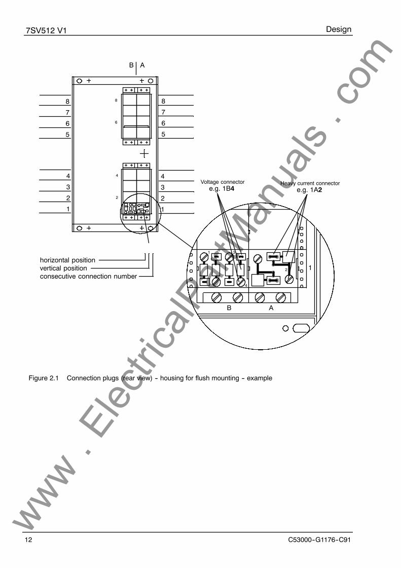
The plug modules are labelled according to theirmounting position by means of a grid system (e.g.1A2). The individual connections within a moduleare numbered consecutively from left to right(when viewed from the rear), (e.g. 1A2); refer toFigure 2.1.
Degree of protection for the housing is IP51, for theterminals IP21. For dimensions please refer to Fig-ure 2.3.
www . El
ectric
alPar
tMan
uals
. com
Design7SV512 V1
C53000--G1176--C9112
Heavy current connectore.g. 1A2
Voltage connectore.g. 1B4
1A2
1
2
21
42
3
1
2
3
4
5
6
7
8
B A
B A
8
7
6
5
4
3
2
1
8
7
6
5
4
3
2
1
1
horizontal positionvertical positionconsecutive connection number
Figure 2.1 Connection plugs (rear view) -- housing for flush mounting -- example
www . El
ectric
alPar
tMan
uals
. com

Design7SV512 V1
13C53000--G1176--C91
2.2 Dimensions
Figures 2.2 and 2.3 show the dimensions of the various types of housing available.
7SV512 Housing for panel surface mounting 7XP2030--1
Max. 60 terminals for cross-section max. 7 mm2
9
71
260
27 29.5
1.5
Interface for opticalfibre below Reset and
paging buttons
39
15
159
144
7.5
46 60
1
16
4531
Earthing terminal 16
30
....
....
....
....
Optical fibre connectors:integrated F--SMA connectore.g for glass fibre 62.5/125 /um
Dimensions in mm
Figure 2.2 Dimensions for housing 7XP2030--1 for panel surface mountingwww . El
ectric
alPar
tMan
uals
. com

Design7SV512 V1
C53000--G1176--C9114
7SV512 Housing for panel flush mounting or cubicle installation 7XP2030--2
Mounting plate
Connector modules
Reset and pagingbuttons
Panel cut-out
29.5
146
105131.5
13.27.3
+2
+0.5
+0.3--
--
5 or M4
6
172 30
1.5
Dimensions in mm
Heavy current connectors:Screwed terminal for max. 4 mm2.Twin spring crimp connector in parallel formax. 2.5 mm2.
Further connectors:Screwed terminal for max. 1.5 mm2.Twin spring crimp connector in parallel formax. 1.5 mm2.
Optical fibre connectors:integrated F--SMA connector,with ceramic post,e.g for glass fibre 62.5/125 /um
8
7
6
5
4
3
2
1
145
D C A
150
8
7
6
5
4
3
2
1
Figure 2.3 Dimensions for housing 7XP2030--2 for panel flush mounting or cubicle installationwww . El
ectric
alPar
tMan
uals
. com

Design7SV512 V1
15C53000--G1176--C91
2.3 Ordering data
Auxiliary voltage
24/48 V dc 2. . . . . . . . . . . . . . . . . . . . . . . . . . . . . . . . . . . . . . . . . . . .
60/110/125 V dc 4. . . . . . . . . . . . . . . . . . . . . . . . . . . . . . . . . . . . . . . .
220/250 V dc 5. . . . . . . . . . . . . . . . . . . . . . . . . . . . . . . . . . . . . . . . . .
Rated current; rated frequency
1 A; 50/60 Hz 1. . . . . . . . . . . . . . . . . . . . . . . . . . . . . . . . . . .
5 A; 50/60 Hz 5. . . . . . . . . . . . . . . . . . . . . . . . . . . . . . . . . . .
7. 8. 9. 10. 11. 12. 13. 14.
A 0
Numerical Circuit Breaker
Failure Protection 7 S V 5 1 2
Construction
in housing 7XP2030 for panel surface mounting B. . . . . . . . . . . . . . . .
in housing 7XP2030 for panel flush mounting orcubicle installation C. . . . . . . . . . . . . . . . . . . . . . . . . . . . . . . . . . . . . . . . . .
Serial interface for coupling to a control centre
without serial interface A. . . . . . . . . . . . . . . . . . . . . . . . . . . . . . . . . . . . . . . . . . . . . . . . . . . . . . . . . . . . . .
with serial interface for optical fibre connection C. . . . . . . . . . . . . . . . . . . . . . . . . . . . . . . . . . . . . . . . .
0
Supplementary annunciation functions
without 0. . . . . . . . . . . . . . . . . . . . . . . . . . . . . . . . . . . . . . . . . . . . . . . . . . . . . . . . . . . . . . . .
with real time clock and non-volatile annunciation memories 1. . . . . . . . . . . . . . . . . .
--- ---
15. 16.
A 0
www . El
ectric
alPar
tMan
uals
. com

Technical data7SV512 V1
C53000---G1176---C9116
3 Technical data
3.1 General data
3.1.1 Inputs/outputs
Measuring circuits
Rated current IN 1 A or 5 A
Rated frequency fN 50 Hz/60 Hz (settable)
Power consumption current path at IN = 1 A approx 0.1 VA per phase and earth currentcurrent path at IN = 5 A approx 0.2 VA per phase and earth current
Overload capability current path, phases and earth--- thermal (rms) 100 ¢ IN for ±1 s
20 ¢ IN for ±10 s4 ¢ IN continuous
--- dynamic (pulse current) 250 ¢ IN one half cycle
Auxiliary voltage
Power supply via integrated dc/dc converter
Rated auxiliary voltage UH 48/60 Vdc 110/125 Vdc 220/250 Vdc
38 to 69 Vdc 88 to 144 Vdc 176 to 288 VdcPermissible variations
Superimposed ac voltage, peak-to-peak ± 12 % at rated voltage± 6 % at limits of admissible voltage
Power consumption quiescent approx 6.5 Wenergized approx 13.5 W
Bridging time during failure/short-circuitof auxiliary voltage ² 50 ms at Udc ² 110 Vdc
Heavy duty (command) contacts
Command (trip) relays, number 5Contacts per relay 2 NO
Switching capacityMAKE 1000 W/VABREAK 30 W/VA
Switching voltage 250 VPermissible current 5 A continuous
30 A for 0.5 s
www . El
ectric
alPar
tMan
uals
. com

Technical data7SV512 V1
17C53000---G1176---C91
Signal contacts
Signal/alarm relays 8
Contact per relay 1 CO or 1 NO
Switching capacityMAKE/BREAK 20 W/VA
Switching voltage 250 V
Permissible current 1 A
Binary inputs
Number 10Operating voltage 24 to 250 VdcCurrent consumption, energized approx 1.7 mA,
independent of operating voltage
Serial interfaces
Operator terminal interface non-isolated
--- Connection at the front, 25-pole subminiature connectoracc. ISO 2110for connection of a personal computer or similar
--- Transmission speed as delivered 1200 Baudmin 1200 Baud, max 19200 Baud
Interface for data transfer to a control centre optical fibre connection
--- Standards protocol according to DIN 19244
--- Transmission speed as delivered 9600 Baudmin 4800 Baud, max 19200 Baud
--- Transmission security Hamming distance d = 4
--- Connection optical fibre integrated F---SMA connector for direct opticalfibre connection, with ceramic post,e.g. glass fibre 62.5/125 �mfor flush mounted housing: at the rearfor surface mounted housing: on the bottom cover
Optical wave length 820 nmPermissible line attenuation max 8 dBTransmission distance max 1.5 kmNormal signal position reconnectable; factory setting: ”light off”
www . El
ectric
alPar
tMan
uals
. com
Technical data7SV512 V1
C53000---G1176---C9118
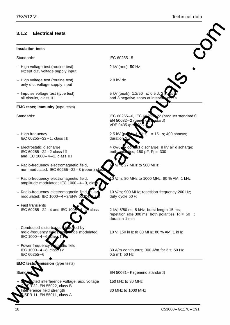
3.1.2 Electrical tests
Insulation tests
Standards: IEC 60255---5
--- High voltage test (routine test) 2 kV (rms); 50 Hzexcept d.c. voltage supply input
--- High voltage test (routine test) 2.8 kV dconly d.c. voltage supply input
--- Impulse voltage test (type test) 5 kV (peak); 1.2/50 �s; 0.5 J; 3 positiveall circuits, class III and 3 negative shots at intervals of 5 s
EMC tests; immunity (type tests)
Standards: IEC 60255---6, IEC 60255---22 (product standards)EN 50082---2 (generic standard)VDE 0435 /part 303
--- High frequency 2.5 kV (peak); 1 MHz; �=15 �s; 400 shots/s;IEC 60255---22---1, class III duration 2 s
--- Electrostatic discharge 4 kV/6 kV contact discharge; 8 kV air discharge;IEC 60255---22---2 class III both polarities; 150 pF; Ri = 330 �and IEC 1000---4---2, class III
--- Radio-frequency electromagnetic field, 10 V/m; 27 MHz to 500 MHznon-modulated; IEC 60255---22---3 (report) class ���
--- Radio-frequency electromagnetic field, 10 V/m; 80 MHz to 1000 MHz; 80 % AM; 1 kHzamplitude modulated; IEC 1000---4---3, class ���
--- Radio-frequency electromagnetic field, pulse 10 V/m; 900 MHz; repetition frequency 200 Hz;modulated; IEC 1000---4---3/ENV 50204, class ��� duty cycle 50 %
--- Fast transientsIEC 60255---22---4 and IEC 1000---4---4, class ��� 2 kV; 5/50 ns; 5 kHz; burst length 15 ms;
repetition rate 300 ms; both polarities; Ri = 50 �;duration 1 min
--- Conducted disturbances induced byradio-frequency fields, amplitude modulated 10 V; 150 kHz to 80 MHz; 80 % AM; 1 kHzIEC 1000---4---6, class III
--- Power frequency magnetic fieldIEC 1000---4---8, class IV 30 A/m continuous; 300 A/m for 3 s; 50 HzIEC 60255---6 0.5 mT; 50 Hz
EMC tests; emission (type tests)
Standard: EN 50081---K (generic standard)
--- Conducted interference voltage, aux. voltage 150 kHz to 30 MHzCISPR 22, EN 55022, class B
--- Interference field strength 30 MHz to 1000 MHzCISPR 11, EN 55011, class Awww .
Elec
tricalP
artM
anua
ls . c
om
Technical data7SV512 V1
19C53000---G1176---C91
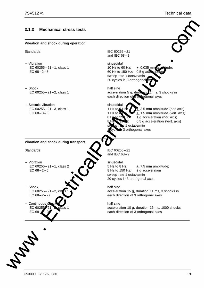
3.1.3 Mechanical stress tests
Vibration and shock during operation
Standards: IEC 60255---21and IEC 68---2
--- Vibration sinusoidalIEC 60255---21---1, class 1 10 Hz to 60 Hz: + 0.035 mm amplitude;IEC 68---2---6 60 Hz to 150 Hz: 0.5 g acceleration
sweep rate 1 octave/min20 cycles in 3 orthogonal axes
--- Shock half sineIEC 60255---21---2, class 1 acceleration 5 g, duration 11 ms, 3 shocks in
each direction of 3 orthogonal axes
--- Seismic vibration sinusoidalIEC 60255---21---3, class 1 1 Hz to 8 Hz: + 3.5 mm amplitude (hor. axis)IEC 68---3---3 1 Hz to 8 Hz: + 1.5 mm amplitude (vert. axis)
8 Hz to 35 Hz: 1 g acceleration (hor. axis)8 Hz to 35 Hz: 0.5 g acceleration (vert. axis)sweep rate 1 octave/min1 cycle in 3 orthogonal axes
Vibration and shock during transport
Standards: IEC 60255---21and IEC 68---2
--- Vibration sinusoidalIEC 60255---21---1, class 2 5 Hz to 8 Hz: + 7.5 mm amplitude;IEC 68---2---6 8 Hz to 150 Hz: 2 g acceleration
sweep rate 1 octave/min20 cycles in 3 orthogonal axes
--- Shock half sineIEC 60255---21---2, class 1 acceleration 15 g, duration 11 ms, 3 shocks inIEC 68---2---27 each direction of 3 orthogonal axes
--- Continuous shock half sineIEC 60255---21---2, class 1 acceleration 10 g, duration 16 ms, 1000 shocksIEC 68---2---29 each direction of 3 orthogonal axes
www . El
ectric
alPar
tMan
uals
. com

Technical data7SV512 V1
C53000---G1176---C9120
3.1.4 Climatic stress tests
--- Permissible ambient temperature
during service ---5 �C to +55 �Cduring storage ---25 �C to +55 �Cduring transport ---25 �C to +70 �C
Storage and transport with standard works packaging!
--- Permissible humidity mean value per year ± 75 % relative humidity;on 30 days per year 95 % relative humidity;Condensation not permissible!
We recommend that all units are installed such that they are not subjected to direct sunlight, nor to large tem-perature fluctuations which may give rise to condensation.
3.1.5 Service conditions
The relay is designed for use in industrial environ-ment, for installation in standard relay rooms andcompartments so that with proper installation elec-tro-magnetic compatibility (EMC) is ensured. Thefollowing should also be heeded:
--- All contactors and relays which operate in thesame cubicle or on the same relay panel as thedigital protection equipment should, as a rule, befitted with suitable spike quenching elements.
--- All external connection leads in sub-stations from100 kV upwards should be screened with ascreen capable of carrying power currents andearthed at both sides. No special measures are
normally necessary for sub-stations of lower volt-ages.
--- It is not permissible to withdraw or insert individu-al modules under voltage. In the withdrawn condi-tion, some components are electrostatically en-dangered; during handling the standards forelectrostatically endangered components mustbe observed. The modules are not endangeredwhen plugged in.
WARNING! The relay is not designed for use in resi-dential, commercial or light-industrial environmentas defined in EN 50081.
3.1.6 Design
Housing 7XP20; refer Section 2.1
Dimensions refer Section 2.2
Weight (mass)--- in housing for surface mounting approx 11.0 kg--- in housing for flush mounting approx 9.5 kg
Degree of protection acc. to EN 60529--- Housing IP 51--- Terminals IP 21www .
Elec
tricalP
artM
anua
ls . c
om

Technical data7SV512 V1
21C53000---G1176---C91
3.2 Circuit breaker failure protection
Breaker supervision
Current detectionsetting range 0.05 IN to 4.00 IN (steps 0.01 IN)
drop-off ratio approx. 0.9
tolerance 0.01 ¡ IN or 5 % of set value
Supervision via breaker auxiliary contactswith three-pole control 1 input for breaker auxiliary contactwith single-pole control 1 input for each pole or
1 input for parallel connection and 1 input forseries connection of the breaker auxiliary contacts
Note: The breaker failure protection can operate even without the mentioned breaker auxiliary contacts but with reduced scope of functions.The auxiliary contacts are necessary for
Breaker failure protection after a trip without or end fault protection,with insufficient current flow (e.g. Buchholz protection), pole discrepancy supervision.
Initiation conditions
for breaker failure protection single-pole trip from feeder protectionthree-pole trip from feeder protectionthree-pole trip from bus-bar protectionthree-pole trip from non-short-circuit protection
Times
pick-up time approx. 5 ms with measured quantities presentapprox. 20 ms after switch-on of meas. quantities
drop-off time with sinusoidal measured quantities < 10 msdrop-off time maximum < 20 ms
delay times for all time stages 0.00 s to 32.00 s (steps 0.01 ms) or 1
delay time tolerance 1 % of set value or 10 ms
The set times are pure delay times.
3.3 Circuit breaker pole discrepancy supervision
Start criterion any pole open and any pole closed
Supervision time 0.00 s to 32.00 s (steps 0.01 ms) or 1
delay time tolerance 1 % of set value or 10 mswww . El
ectric
alPar
tMan
uals
. com

Technical data7SV512 V1
C53000---G1176---C9122
3.4 Ancillary functions
Output of measured values
Operational values of currents IL1, IL2, IL3, and IE (if connected)in A primary and in % IN
Measuring tolerances ± 2 % of rated value
Measured values plausibility checks--- Sum of currents phases and earth
Steady-state measured value supervision
Current unbalance Imax/Imin > symmetry factoras long as I > Ilimit
Fault event data storage
Storage of annunciations of the last three faults
Real time clock (optional)
Resolution for operational annunciations 1 minResolution for fault event annunciations 1 ms
Clock module (optional) DALLAS Type DS 138 --- 32kRAMifield TIMEKEEPERSelf-discharge time >10 years
Max time deviation 0.01 %
Data storage for fault recording
Storage period (fault detection = 0 ms), max.--- for operating interface ---100 ms to +2900 ms at 50 Hz
--- 83 ms to +2416 ms at 60 Hz--- for LSA interface --- 60 ms to + 600 ms at 50 Hz
--- 50 ms to + 500 ms at 60 HzSampling rate 1 instantaneous value per ms at 50 Hz
1 instantaneous value per 0.83 ms at 60 Hz
www . El
ectric
alPar
tMan
uals
. com
Method of operation7SV512 V1
23C53000---G1176---C91
4 Method of operation
4.1 Operation of complete unit
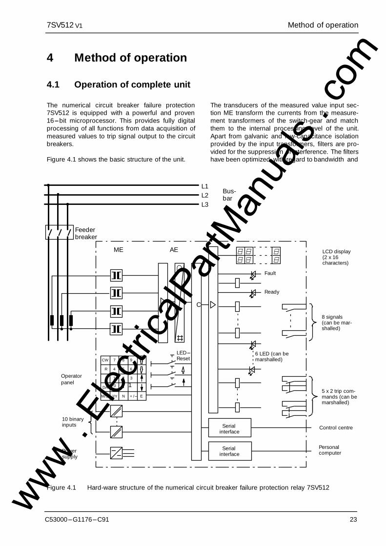
The numerical circuit breaker failure protection7SV512 is equipped with a powerful and proven16---bit microprocessor. This provides fully digitalprocessing of all functions from data acquisition ofmeasured values to trip signal output to the circuitbreakers.
Figure 4.1 shows the basic structure of the unit.
The transducers of the measured value input sec-tion ME transform the currents from the measure-ment transformers of the switch-gear and matchthem to the internal processing level of the unit.Apart from galvanic and low-capacitance isolationprovided by the input transformers, filters are pro-vided for the suppression of interference. The filtershave been optimized with regard to bandwidth and
Serialinterface
Serialinterface
PersonalcomputerPower
supply
10 binaryinputs
Operatorpanel
M/S
ME AE
∩
LED---ResetCW 7 8 9
R
F
DA
4 5 6
1 2 3
0 ¡ 1
J/Y N +/--- E
�C
L1L2L3
Bus-bar
Feederbreaker
LCD display(2 x 16characters)
8 signals(can be mar-shalled)
5 x 2 trip com-mands (can bemarshalled)
Control centre
Fault
Ready
6 LED (can bemarshalled)
Figure 4.1 Hard-ware structure of the numerical circuit breaker failure protection relay 7SV512www . El
ectric
alPar
tMan
uals
. com
Method of operation7SV512 V1
24 C53000---G1176---C91
processing speed to suit the measured value pro-cessing. The matched analog values are thenpassed to the analog input section AE.
The analog input section AE contains input amplifi-ers, sample and hold elements for each input, ana-log--- to---digital converters and memory circuits forthe data transfer to the microprocessor.
Apart from control and supervision of the measuredvalues, the microprocessor processes the actualprotective functions. These include in particular:
--- filtering and formation of the measured quantities,
--- continuous interrogation of the binary input whichare used for initiation,
--- continuous calculation of the currents,--- plausibility checks on the measured currents and
the starting conditions,
--- scanning of limit values and time sequences,
--- decision on trip commands,
--- Storage of instantaneous current and voltage val-ues during a fault for analysis.
Binary inputs and outputs to and from the processorare channelled via the input/output elements. Fromthese the processor receives information from theswitch-gear (e.g. remote resetting) or from otherequipment (e.g. blocking signals). Outputs include,in particular, trip commands to the circuit breakers,signals for remote signalling of important events and
conditions as well as visual indicators (LEDs) and analphanumerical display on the front.
An integrated membrane keyboard in connectionwith a built-in alphanumerical LCD display enablescommunication with the unit. All operational datasuch as setting values, plant data, etc. are enteredinto the protection from this panel (refer Section 6.3).Using this panel the parameters can be recalled andthe relevant data for the evaluation of a fault can beread out after a fault has occurred (refer Section 6.4).The dialog with the relay can be carried out alterna-tively via the serial interface on the front plate bymeans of an operator panel or a personal computer.
Via a second serial interface (option), fault data canbe transmitted to a central evaluation unit. Duringhealthy operation, measured values (e.g. load cur-rents) can also be transmitted. This second interfaceis designed for connection of optical fibre links, pro-vided this interface is accordingly ordered (referSection 2.3 Ordering data).
A power supply unit provides the auxiliary supply onthe various voltage levels to the described functionalunits. +18 V is used for the relay output circuits. Theanalog input circuits require ±15 V whereas the pro-cessor and its immediate peripherals are suppliedwith +5 V. Transient failures in the supply voltage, upto 50 ms, which may occur during short-circuits inthe dc supply system of the plant are bridged by a dcvoltage storage element (rated auxiliary voltage>110 Vdc).
www . El
ectric
alPar
tMan
uals
. com
Method of operation7SV512 V1
25C53000---G1176---C91
4.2 Circuit breaker failure protection
4.2.1 General
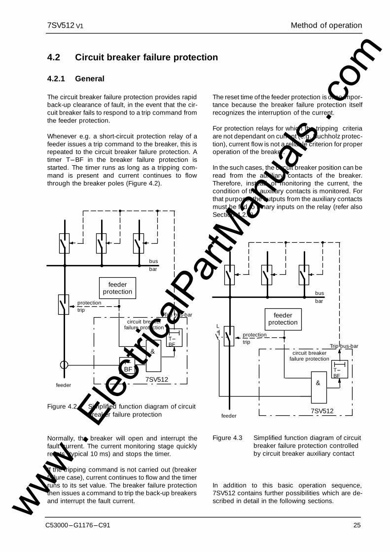
The circuit breaker failure protection provides rapidback-up clearance of fault, in the event that the cir-cuit breaker fails to respond to a trip command fromthe feeder protection.
Whenever e.g. a short-circuit protection relay of afeeder issues a trip command to the breaker, this isrepeated to the circuit breaker failure protection. Atimer T---BF in the breaker failure protection isstarted. The timer runs as long as a tripping com-mand is present and current continues to flowthrough the breaker poles (Figure 4.2).
feederprotection
I---BF
&
T---BF
protectiontrip
Trip bus-barcircuit breaker
failure protection
7SV512feeder
busbar
Figure 4.2 Simplified function diagram of circuitbreaker failure protection
Normally, the breaker will open and interrupt thefault current. The current monitoring stage quicklyresets (typical 10 ms) and stops the timer.
If the tripping command is not carried out (breakerfailure case), current continues to flow and the timerruns to its set value. The breaker failure protectionthen issues a command to trip the back-up breakersand interrupt the fault current.
The reset time of the feeder protection is of no impor-tance because the breaker failure protection itselfrecognizes the interruption of the current.
For protection relays for which the tripping criteriaare not dependant on current (e.g. Buchholz protec-tion), current flow is not a reliable criterion for properoperation of the breaker.
In the such cases, the circuit breaker position can beread from the auxiliary contacts of the breaker.Therefore, instead of monitoring the current, thecondition of the auxiliary contacts is monitored. Forthat purpose, the outputs from the auxiliary contactsmust be fed to binary inputs on the relay (refer alsoSection 4.2.3).
&
7SV512
L+
feederprotection
protectiontrip
Trip bus-barcircuit breaker
failure protection
feeder
busbar
T---BF
Figure 4.3 Simplified function diagram of circuitbreaker failure protection controlledby circuit breaker auxiliary contact
In addition to this basic operation sequence,7SV512 contains further possibilities which are de-scribed in detail in the following sections.www .
Elec
tricalP
artM
anua
ls . c
om
Method of operation7SV512 V1
26 C53000---G1176---C91
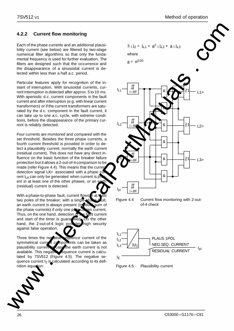
4.2.2 Current flow monitoring
Each of the phase currents and an additional plausi-bility current (see below) are filtered by two-stagenumerical filter algorithms so that only the funda-mental frequency is used for further evaluation. Thefilters are designed such that the occurrence andthe disappearance of a sinusoidal current is de-tected within less than a half a.c. period.
Particular features apply for recognition of the in-stant of interruption. With sinusoidal currents, cur-rent interruption is detected after approx. 5 to 10 ms.With aperiodic d.c. current components in the faultcurrent and after interruption (e.g. with linear currenttransformers) or if the current transformers are satu-rated by the d.c. component in the fault current, itcan take up to one a.c. cycle, with extreme condi-tions, before the disappearance of the primary cur-rent is reliably detected.
Four currents are monitored and compared with theset threshold. Besides the three phase currents, afourth current threshold is provided in order to de-tect a plausibility current, normally the earth current(residual current). This does not have any direct in-fluence on the basic function of the breaker failureprotection but it allows a 2-out-of-4 comparison to bemade (refer Figure 4.4). This means that the currentdetection signal LK> associated with a phase cur-rent ILK can only be generated when current is pres-ent in at least one of the other phases, or an earth(residual) current is detected.
With a phase-to-phase fault, current flows in at leasttwo poles of the breaker; with a single-phase fault,an earth current is always present (residual sum ofthe phase currents) if only one pole carries current.Thus, on the one hand, detection of the fault currentand start of the timer is guaranteed. On the otherhand, the 2-out-of-4 logic provides high securityagainst false operation.
Three times the negative sequence current of thesymmetrical current components can be taken asplausibility current in case the earth current is notavailable. This negative sequence current is calcu-lated by 7SV512 (Figure 4.5). The negative se-quence current I2 is calculated according to its defi-nition equation:
3 ¡ I2 = IL1 + a2 ¡ IL2 + a ¡ IL3
where
a = ej120�
&
&
&
&
&
&
>=1
>=1
>=1
IL1
IL2
IL3
I---BF
I---BF
I---BF
Ipl I---BF
L1>
L2>
L3>
Figure 4.4 Current flow monitoring with 2-out-of-4 check
IL1IL2IL3
IE
3¡I2 Ipl
PLAUS 1POLNEG.SEQ. CURRENT
RESIDUAL CURRENT
Figure 4.5 Plausibility current
www . El
ectric
alPar
tMan
uals
. com

Method of operation7SV512 V1
27C53000---G1176---C91
4.2.3 Processing of the circuit breaker auxiliary contacts
Current flow is not a reliable criterion for proper oper-ation of the circuit breaker for faults which do notcause detectable current flow (e.g. Buchholz pro-tection). Information about the position of the circuitbreaker auxiliary contacts is required in these casesto check correct response of the circuit breaker. Ifthe breaker poles can be switched individually, infor-mation about the position of each individual circuitbreaker pole is useful (but not always a precondi-tion).
The relay incorporates a circuit breaker position log-ic (Figure 4.7), which offers various possibilities, de-pendent of which auxiliary contacts are availablefrom the circuit breaker and how they are connectedto binary inputs of the relay.
If the circuit breaker is switched only three-pole, itsauxiliary contact is connected to a binary input mod-ule which is assigned to the input function ”>CBAux. 1p C” (BI 20 in Figure 4.7). The remaininginputs in the figure are not used then.
If the circuit breaker poles can be switched individu-ally but only the parallel connected auxiliary con-tacts are available, then the binary input for this con-nection must be assigned exclusively to the inputfunction ”>CB Aux. 1p C” (BI 20 in Figure 4.7).The remaining inputs in the figure are not used then.
If the circuit breaker poles can be switched individu-ally and each individual auxiliary contact is availablethen it is recommended to connect the auxiliary con-tact of each individual pole to an individual binary in-put. This connection allows maximum information tobe processed in the relay. The assignment of thebinary inputs is as follows:
--- auxiliary contact of pole L1 assigned to input func-tion ”>CB Aux. L1” (BI 16 in Figure 4.7),
--- auxiliary contact of pole L2 assigned to input func-tion ”>CB Aux. L2” (BI 17 in Figure 4.7),
--- auxiliary contact of pole L3 assigned to input func-tion ”>CB Aux. L3” (BI 18 in Figure 4.7).
Binary inputs BI 19 and BI 20 are not used in thiscase. This connection mode is recommended if thebreaker failure protection can be initiated by a feederprotection function which may trip at low-current orno-current conditions and which shall operate inconjunction with single-pole auto-reclosure (e.g.weak-infeed trip with carrier transmission).
If the circuit breaker poles can be switched individu-ally but only two binary inputs can be used, one canconnect the parallel connection of one set of auxilia-ry contacts to a binary input and the series connec-tion to another. The inputs are assigned to the func-tion ”>CB Aux. 1p C” (BI 20 in Figure 4.7) for theparallel connection and to ”>CB Aux. 3p C” (BI 19in Figure 4.7) for the series connection. A single-poletrip command is assumed to be executed, when theseries connection is interrupted.
Note that Figure 4.7 shows the total logic for all theconnection possibilities. In the actual case a part ofthe inputs and logic is only used, as describedabove.
The 8 outputs of the circuit breaker position logic areprocessed by the protection functions. The outputsignals are blocked as long as the input signals arenot plausible: e.g. a circuit breaker pole cannot beopen and closed at the same time.
Evaluation of the breaker auxiliary contacts is car-ried out in the breaker failure protection function onlyas long as the current flow monitoring has notpicked up. Once the current flow criterion has beendetected during trip signal of the protection, the cir-cuit breaker is assumed to be open as soon as thecurrent has disappeared, even when the associatedauxiliary contact does not (yet) indicate that the cir-cuit breaker has opened (Figure 4.6). This givespreference to the more reliable current criterion andavoids overfunctioning due to a defect e.g. in theauxiliary contact mechanism or circuit. This interlockfeature is provided for each individual phase as wellas for three-pole trip; in the latter case the ”any poleclosed” output as illustrated in Figure 4.7 is decisivefor the ”CB aux. contact” signal of Figure 4.6.
&
R
&
S Q Auxiliarycontact
criterion
Aux
currentflow
prot.trip
CB aux.contact
Figure 4.6 Interlock of the auxiliary contact cri-terion
www . El
ectric
alPar
tMan
uals
. com

Method of operation7SV512 V1
28 C53000---G1176---C91
BI 20 A20
BI 16
>1
>1
>1
BI 17>1
>1
BI 18>1
>1
BI 19
>1
&
L1
L1
L2
L2
L3
L3
L2 L3L1
&
&
&
&
&
&
&
plausibilitycheck
8
A20
A16
A16
A17
A17
A18
A18
A19
A19
L1 closed
L1 open
any poleclosed
any poleopen
CB aux. contacts:
L1, L2, L3 Circuit breaker auxiliary contactsBI .. Binary input with associated function numberA.. Binary input is assigned to physical input
L2 closed
L2 open
L3 closed
L3 open
Figure 4.7 Circuit breaker position logicwww . El
ectric
alPar
tMan
uals
. com
Method of operation7SV512 V1
29C53000---G1176---C91
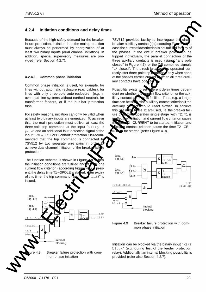
4.2.4 Initiation conditions and delay times
Because of the high safety demand for the breakerfailure protection, initiation from the main protectionmust always be performed by energization of atleast two binary inputs (dual channel initiation). Inaddition, special supervisory measures are pro-vided (refer Section 4.2.7).
4.2.4.1 Common phase initiation
Common phase initiation is used, for example, forlines without automatic reclosure (e.g. cables), forlines with only three-pole auto-reclosure (e.g. inoverhead line systems without earthed neutral), fortransformer feeders, or if the bus-bar protectiontrips.
For safety reasons, initiation can only be valid whenat least two binary inputs are energized. To achievethis, the main protection must deliver at least thethree-pole trip command at the input ”>Trip 3pole” and an additional fault detection signal at theinput ”>Start”. For Buchholz protection it is recom-mended that the trip command is connected to7SV512 by two separate wire pairs in order toachieve dual channel initiation of the breaker failureprotection.
The function scheme is shown in Figure 4.8. Whenthe initiation conditions are fulfilled and at least onecurrent flow criterion (according Figure 4.4) is pres-ent, the delay time T1---3POLE is started. After expiryof this time, the trip command ”BFP Trip L123” isissued.
>1
&
&
& T1---3POLE
BFP
Trip L123
L1>
L2>
L3>
(acc.Fig 4.4)
>Trip 3pole
>B/F
block
internalblocking
>Start
Aux(acc.Fig 4.6)
Figure 4.8 Breaker failure protection with com-mon phase initiation
7SV512 provides facility to interrogate the circuitbreaker auxiliary contact(s) (according Figure 4.6) incase the current flow criterion is not fulfilled for any ofthe phases. If the circuit breaker poles can betripped individually, the parallel connection of thethree auxiliary contacts is used (signal ”any poleclosed” in Figure 4.7), or the OR combined signals”L* closed”. The circuit breaker has operated cor-rectly after three-pole trip command only when noneof the phases carries current or when all three auxil-iary contacts have opened.
Possibility exists to set different delay times depen-dent on whether the current flow criterion or the aux-iliary contact criterion is fulfilled. Thus, e.g. a longertime can be set for the auxiliary contact criterion if theauxiliary contacts could react slower. To achievethis, the delay times T2 are used, i.e. the breaker fail-ure protection operates single-stage with T2; T1 isineffective. Initiation and current flow criterion causethe time T2---CURRENT to be started, initiation andauxiliary contact criterion cause the time T2---CB---AUX to be started (refer Figure 4.9).
>1
&
&
&
T2---CB---AUX
BFPTrip BB
L1>
L2>
L3>
(acc.Fig 4.4)
>Trip 3pole
>B/Fblock
internalblocking
>Start
Aux(acc.Fig 4.6) &
T2---CURR.
>1
Figure 4.9 Breaker failure protection with com-mon phase initiation
Initiation can be blocked via the binary input ”>B/Fblock” (e.g. during test of the feeder protectionrelay). Additionally, an internal blocking possibility isprovided (refer also Section 4.2.7).
www . El
ectric
alPar
tMan
uals
. com
Method of operation7SV512 V1
30 C53000---G1176---C91
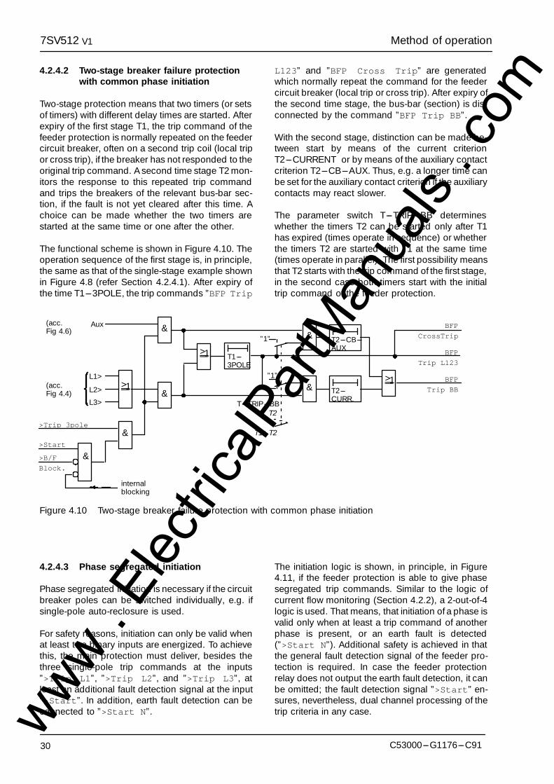
4.2.4.2 Two-stage breaker failure protectionwith common phase initiation
Two-stage protection means that two timers (or setsof timers) with different delay times are started. Afterexpiry of the first stage T1, the trip command of thefeeder protection is normally repeated on the feedercircuit breaker, often on a second trip coil (local tripor cross trip), if the breaker has not responded to theoriginal trip command. A second time stage T2 mon-itors the response to this repeated trip commandand trips the breakers of the relevant bus-bar sec-tion, if the fault is not yet cleared after this time. Achoice can be made whether the two timers arestarted at the same time or one after the other.
The functional scheme is shown in Figure 4.10. Theoperation sequence of the first stage is, in principle,the same as that of the single-stage example shownin Figure 4.8 (refer Section 4.2.4.1). After expiry ofthe time T1---3POLE, the trip commands ”BFP Trip
L123” and ”BFP Cross Trip” are generatedwhich normally repeat the command for the feedercircuit breaker (local trip or cross trip). After expiry ofthe second time stage, the bus-bar (section) is dis-connected by the command ”BFP Trip BB”.
With the second stage, distinction can be made be-tween start by means of the current criterionT2---CURRENT or by means of the auxiliary contactcriterion T2---CB---AUX. Thus, e.g. a longer time canbe set for the auxiliary contact criterion if the auxiliarycontacts may react slower.
The parameter switch T---TRIP---BB determineswhether the timers T2 can be started only after T1has expired (times operate in sequence) or whetherthe timers T2 are started with T1 at the same time(times operate in parallel). The first possibility meansthat T2 starts with the trip command of the first stage,in the second case both timers start with the initialtrip command of the feeder protection.
>1
&
&
&
T1---3POLE
BFP
Trip L123
L1>
L2>
L3>
(acc.Fig 4.4)
>Trip 3pole
>B/F
Block.
internalblocking
>Start
Aux(acc.Fig 4.6)
>1
&
&
&
>1
”1”
”1”
T---TRIP---BBT2
T1+T2
T2---CB---AUX
T2---CURR.
BFP
Trip BB
BFP
CrossTrip
Figure 4.10 Two-stage breaker failure protection with common phase initiation
4.2.4.3 Phase segregated initiation
Phase segregated initiation is necessary if the circuitbreaker poles can be switched individually, e.g. ifsingle-pole auto-reclosure is used.
For safety reasons, initiation can only be valid whenat least two binary inputs are energized. To achievethis, the main protection must deliver, besides thethree single-pole trip commands at the inputs”>Trip L1”, ”>Trip L2”, and ”>Trip L3”, atleast an additional fault detection signal at the input”>Start”. In addition, earth fault detection can beconnected to ”>Start N”.
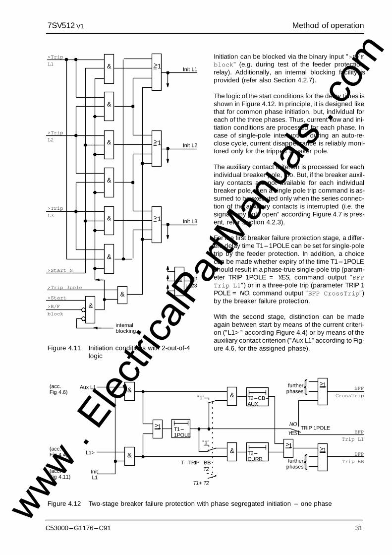
The initiation logic is shown, in principle, in Figure4.11, if the feeder protection is able to give phasesegregated trip commands. Similar to the logic ofcurrent flow monitoring (Section 4.2.2), a 2-out-of-4logic is used. That means, that initiation of a phase isvalid only when at least a trip command of anotherphase is present, or an earth fault is detected(”>Start N”). Additional safety is achieved in thatthe general fault detection signal of the feeder pro-tection is required. In case the feeder protectionrelay does not output the earth fault detection, it canbe omitted; the fault detection signal ”>Start” en-sures, nevertheless, dual channel processing of thetrip criteria in any case.www .
Elec
tricalP
artM
anua
ls . c
om
Method of operation7SV512 V1
31C53000---G1176---C91
&
&
&
&
&
&
>=1
>=1
>=1
Init L1
&>B/F
block
internalblocking
>Start
>Trip
L1
>Trip
L2
>Trip
L3
>Start N
Init L2
Init L3
& InitL123>Trip 3pole
&
Figure 4.11 Initiation conditions with 2-out-of-4logic
Initiation can be blocked via the binary input ”>B/Fblock” (e.g. during test of the feeder protectionrelay). Additionally, an internal blocking facility isprovided (refer also Section 4.2.7).
The logic of the start conditions for the delay times isshown in Figure 4.12. In principle, it is designed likethat for common phase initiation, but, individual foreach of the three phases. Thus, current flow and ini-tiation conditions are processed for each phase. Incase of single-pole interruption during an auto-re-close cycle, current disappearance is reliably moni-tored only for the tripped breaker pole.
The auxiliary contact criterion is processed for eachindividual breaker pole, too. But, if the breaker auxil-iary contacts are not available for each individualbreaker pole, then a single pole trip command is as-sumed to be executed only when the series connec-tion of the auxiliary contacts is interrupted (i.e. thesignal ”any pole open” according Figure 4.7 is pres-ent, refer Section 4.2.3).
For the first breaker failure protection stage, a differ-ent delay time T1---1POLE can be set for single-poletrip by the feeder protection. In addition, a choicecan be made whether expiry of the time T1---1POLEshould result in a phase-true single-pole trip (param-eter TRIP 1POLE = YES, command output ”BFPTrip L1”) or in a three-pole trip (parameter TRIP 1POLE = NO, command output ”BFP CrossTrip”)by the breaker failure protection.
With the second stage, distinction can be madeagain between start by means of the current criteri-on (”L1>” according Figure 4.4) or by means of theauxiliary contact criterion (”Aux L1” according to Fig-ure 4.6, for the assigned phase).
&
T1---1POLE BFP
Trip L1
L1>(acc.Fig 4.4)
Aux L1(acc.Fig 4.6)
>1
&
&
&
>1
”1”
”1”
T---TRIP---BBT2
T1+T2
T2---CB---AUX
T2---CURR.
BFP
Trip BB
BFP
CrossTrip
InitL1
(acc.Fig 4.11)
>1
>1furtherphases
NO
YESTRIP 1POLE
furtherphases
Figure 4.12 Two-stage breaker failure protection with phase segregated initiation --- one phasewww . El
ectric
alPar
tMan
uals
. com
Method of operation7SV512 V1
32 C53000---G1176---C91
&
T1---1POLE
BFP
Trip L1
L1>(acc.Fig 4.4)
Aux L1(acc.Fig 4.6)
>1
&
&
&
>1
”1”
”1”
T---TRIP---BBT2
T1+T2
T2---CB---AUX
T2---CURR.
BFP
Trip BB
BFP
CrossTrip
InitL1
(acc.Fig 4.11)
>1
>1
NOYES
TRIP 1POLE
>1&
T1---3POLE
BFP
Trip L123
L1>
L2>
L3>
(acc.Fig 4.4)
Aux L123(acc.Fig 4.6)
>1
&
&
&
>1
”1”
”1”
T2---CB---AUX
T2---CURR.
InitL123
(acc.Fig 4.11)
¡ ©
§¦
&
T1---1POLE
BFP
Trip L2
L2>(acc.Fig 4.4)
Aux L2(acc.Fig 4.6)
>1
&
&
&
>1
1”
”1”
T2---CB---AUX
T2---CURR.
InitL2
(acc.Fig 4.11)
¢ £
&
T1---1POLE
BFP
Trip L3
L3>(acc.Fig 4.4)
Aux L3(acc.Fig 4.6)
>1
&
&
&
>1
1”
”1”
T2---CB---AUX
T2---CURR.
InitL3
(acc.Fig 4.11)
¤ ¥
©
£
¥
§
¡
¢
¤
¦BFP CBdefTrip
(see Sec---tion 4.2.5)
Figure 4.13 Cooperation of the initiation conditions and delay timerswww . El
ectric
alPar
tMan
uals
. com
Method of operation7SV512 V1
33C53000---G1176---C91
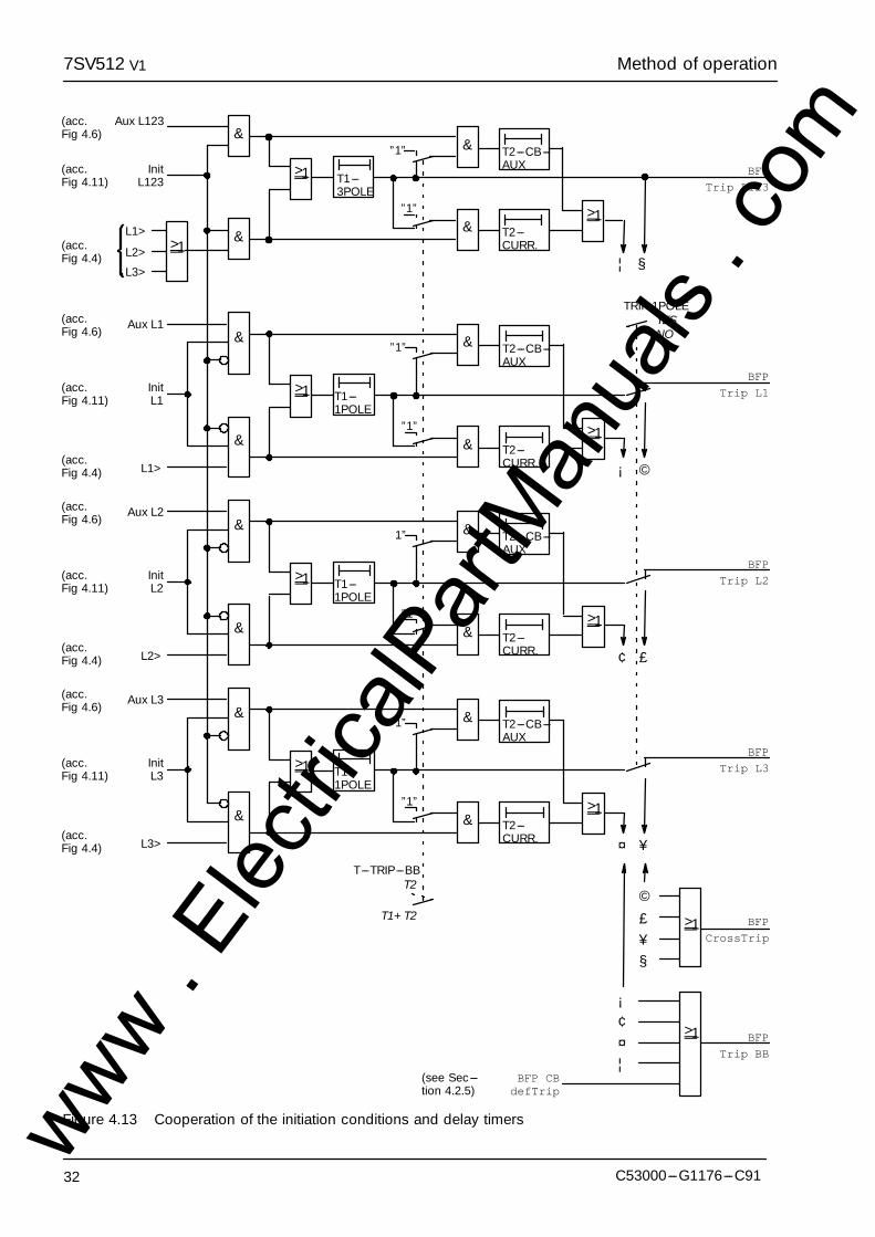
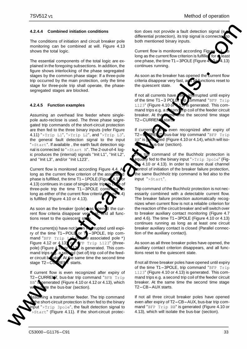
4.2.4.4 Combined initiation conditions
The conditions of initiation and circuit breaker polemonitoring can be combined at will. Figure 4.13shows the total logic.
The essential components of the total logic are ex-plained in the foregoing subsections. In addition, thefigure shows interlocking of the phase segregatedstages by the common phase stage: If a three-poletrip occurred by the main protection, only the timestage for three-pole trip shall operate, the phase-segregated stages are blocked.
4.2.4.5 Function examples
Assuming an overhead line feeder where single-pole auto-reclose is used. The three phase segre-gated trip commands of the short-circuit protectionare then fed to the three binary inputs (refer Figure4.11) ”>Trip L1”, ”>Trip L2”, and ”>Trip L3”,the general fault detection signal to the input”>Start”. If available , the earth fault detection sig-nal is connected to ”>Start N”. The 2-out-of-4 log-ic produces the (internal) signals ”Init L1”, ”Init L2”,and ”Init L3”, and/or ”Init L123”.
Current flow is monitored according Figure 4.4. Aslong as the current flow criterion of the associatedphase is fulfilled, the time T1---1POLE (Figure 4.12 or4.13) continues in case of single-pole trip: in case ofthree-pole trip the time T1---3POLE continues aslong as either of the current flow criteria (Figure 4.4)is fulfilled (Figure 4.10 or 4.13).
As soon as the breaker (pole) has opened the cur-rent flow criteria disappear very fast, and all func-tions reset to the quiescent state.
If the current(s) have not been interrupted until expi-ry of the time T1---POLE or T1---3POLE, trip com-mand ”BFP Trip L*” (for the associated pole *)Figure 4.12 or 4.13), or ”BFP Trip L123” (three-pole) (Figure 4.10 or 4.13), is generated. This com-mand trips e.g. a second (set of) trip coil of the feed-er circuit breaker. At the same time the second timestage T2---CURRENT starts.
If current flow is even recognized after expiry ofT2---CURRENT, bus-bar trip command ”BFB TripBB” is generated (Figure 4.10 or 4.12 or 4.13), whichwill isolate the bus-bar (section).
Assuming a transformer feeder. The trip commandof the short-circuit protection is then fed to the binaryinput ”>Trip 3pole”, the fault detection signal to”>Start” (Figure 4.11). If the short-circuit protec-
tion does not provide a fault detection signal (e.g.differential protection), its trip signal is connected toboth mentioned binary inputs.
Current flow is monitored according Figure 4.4. Aslong as the current flow criterion is fulfilled for at leastone phase, the time T1---3POLE (Figure 4.10 or 4.13)continues running.
As soon as the breaker has opened the current flowcriteria disappear very fast, and all functions reset tothe quiescent state.
If not all currents have been interrupted until expiryof the time T1---3 POLE, trip command ”BFP TripL123” (Figure 4.10 or 4.13) is generated. This com-mand trips e.g. a second trip coil of the feeder circuitbreaker. At the same time the second time stageT2---CURRENT starts.
If current flow is even recognized after expiry ofT2---CURRENT, bus-bar trip command ”BFP TripBB” is generated (Figure 4.10 or 4.14), which will iso-late the bus-bar (section).
The trip command of the Buchholz protection isequally fed to the binary input ”>Trip 3pole” (Fig-ure 4.10 or 4.13). In order to ensure dual channelcontrol of initiation of the breaker failure protection,the same Buchholz trip command is fed also to theinput ”>Start”.
Trip command of the Buchholz protection is not nec-essarily combined with a detectable current flow.The breaker failure protection automatically recog-nizes when current flow is not a reliable criterion forthe reaction of the circuit breaker and will switch overto breaker auxiliary contact monitoring (Figure 4.7and 4.6). The time T1---3POLE (Figure 4.10 or 4.13)continues running as long as at least one circuitbreaker auxiliary contact is closed (Parallel connec-tion of the auxiliary contact).
As soon as all three breaker poles have opened, theauxiliary contact criterion disappears, and all func-tions reset to the quiescent state.
If not all three breaker poles have opened until expiryof the time T1---3POLE, trip command ”BFP TripL123” (Figure 4.10 or 4.13) is generated. This com-mand trips e.g. a second trip coil of the feeder circuitbreaker. At the same time the second time stageT2---CB---AUX starts.
If not all three circuit breaker poles have openedeven after expiry of T2---CB---AUX, bus-bar trip com-mand ”BFP Trip BB” is generated (Figure 4.10 or4.13), which will isolate the bus-bar (section).www .
Elec
tricalP
artM
anua
ls . c
om
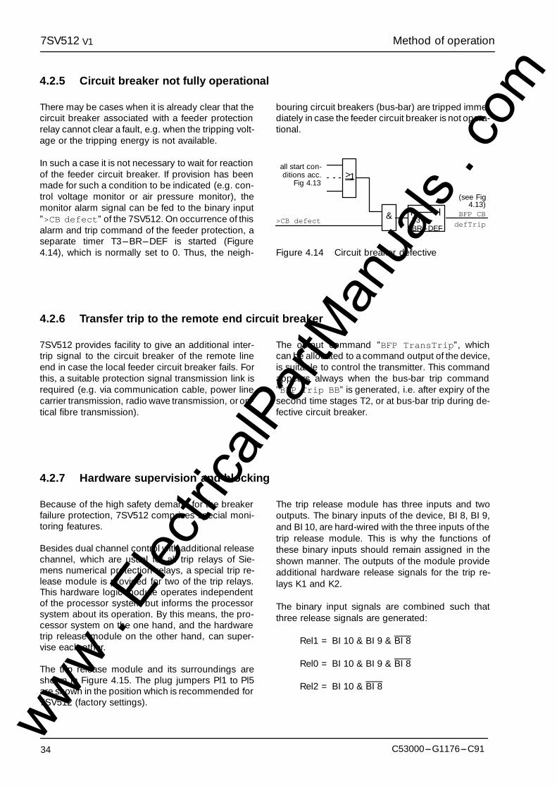
Method of operation7SV512 V1
34 C53000---G1176---C91
4.2.5 Circuit breaker not fully operational
There may be cases when it is already clear that thecircuit breaker associated with a feeder protectionrelay cannot clear a fault, e.g. when the tripping volt-age or the tripping energy is not available.
In such a case it is not necessary to wait for reactionof the feeder circuit breaker. If provision has beenmade for such a condition to be indicated (e.g. con-trol voltage monitor or air pressure monitor), themonitor alarm signal can be fed to the binary input”>CB defect” of the 7SV512. On occurrence of thisalarm and trip command of the feeder protection, aseparate timer T3---BR---DEF is started (Figure4.14), which is normally set to 0. Thus, the neigh-
bouring circuit breakers (bus-bar) are tripped imme-diately in case the feeder circuit breaker is not opera-tional.
& T3---BR---DEF
>CB defect
all start con-ditions acc.
Fig 4.13
BFP CB
defTrip
>1
(see Fig4.13)
Figure 4.14 Circuit breaker defective
4.2.6 Transfer trip to the remote end circuit breaker
7SV512 provides facility to give an additional inter-trip signal to the circuit breaker of the remote lineend in case the local feeder circuit breaker fails. Forthis, a suitable protection signal transmission link isrequired (e.g. via communication cable, power linecarrier transmission, radio wave transmission, or op-tical fibre transmission).
The output command ”BFP TransTrip”, whichcan be allocated to a command output of the device,is suitable to control the transmitter. This commandappears always when the bus-bar trip command”BFP Trip BB” is generated, i.e. after expiry of thesecond time stages T2, or at bus-bar trip during de-fective circuit breaker.
4.2.7 Hardware supervision and blocking
Because of the high safety demand for the breakerfailure protection, 7SV512 comprises special moni-toring features.
Besides dual channel control with additional releasechannel, which are usual for all trip relays of Sie-mens numerical protection relays, a special trip re-lease module is provided for two of the trip relays.This hardware logic module operates independentof the processor system but informs the processorsystem about its operation. By this means, the pro-cessor system on the one hand, and the hardwaretrip release module on the other hand, can super-vise each other.
The trip release module and its surroundings areshown in Figure 4.15. The plug jumpers Pl1 to Pl5are shown in the position which is recommended for7SV512 (factory settings).
The trip release module has three inputs and twooutputs. The binary inputs of the device, BI 8, BI 9,and BI 10, are hard-wired with the three inputs of thetrip release module. This is why the functions ofthese binary inputs should remain assigned in theshown manner. The outputs of the module provideadditional hardware release signals for the trip re-lays K1 and K2.
The binary input signals are combined such thatthree release signals are generated:
Rel1 = BI 10 & BI 9 & BI 8
Rel0 = BI 10 & BI 9 & BI 8
Rel2 = BI 10 & BI 8
www . El
ectric
alPar
tMan
uals
. com
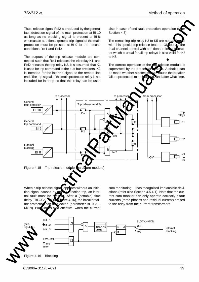
Method of operation7SV512 V1
35C53000---G1176---C91
Thus, release signal Rel2 is produced by the generalfault detection signal of the main protection at BI 10as long as no blocking signal is present at BI 8;whereas an additional general trip signal of the mainprotection must be present at BI 9 for the releaseconditions Rel1 and Rel0.
The outputs of the trip release module are con-nected such that Rel1 releases the trip relay K1, andRel2 releases the trip relay K2. It is assumed that K1is used for trip command to the bus-bar breakers, K2is intended for the intertrip signal to the remote lineend. The trip signal of the main protection relay is notincluded for intertrip so that this relay can be used
also in case of end fault protection operation (referSection 4.3).
The remaining trip relay K3 to K5 are not equippedwith this special trip release feature. Of course, thedual channel control with additional release transis-tor which is usual for all trip relays is also valid for K3to K5.
The correct operation of the trip release module issupervised by the processor system. A choice canbe made whether a defect should cause the breakerfailure protection to be blocked, and after what time.
BI 8
Externalblocking
BI 9
Generaltrip command
BI 10
Pl5
Pl4
to processor to processor
Trip release module
&
&
&
Pl1
from processor
K1
Generalfault detection
Rel1
Rel0
Rel2
Pl2
Pl3
Triprelays
K2
K3to
K5
Figure 4.15 Trip release module (hardware module)
When a trip release signal appears without an initia-tion signal caused by main protection trip, an inter-nal fault must be present. After a (settable) timedelay TBLOCK---MON (Figure 4.16), the breaker fail-ure protection can be blocked (parameter BLOCK---MON). Blocking is also effective, when the current
sum monitoring �I has recognized implausible devi-ations (refer also Section 4.5.4.1). Note that the cur-rent sum monitor can only operate correctly if fourcurrents (three phases and residual current) are fedto the relay from the current transformers.
TBLOCKMON
>1
>1
& S Q
R
BLOCK---MON
YES
NOinternalblocking
I mo-nitor
HW---Rel.
Init L1(acc.Fig 4.11)
Init L2
Init L3
Figure 4.16 Blockingwww . El
ectric
alPar
tMan
uals
. com
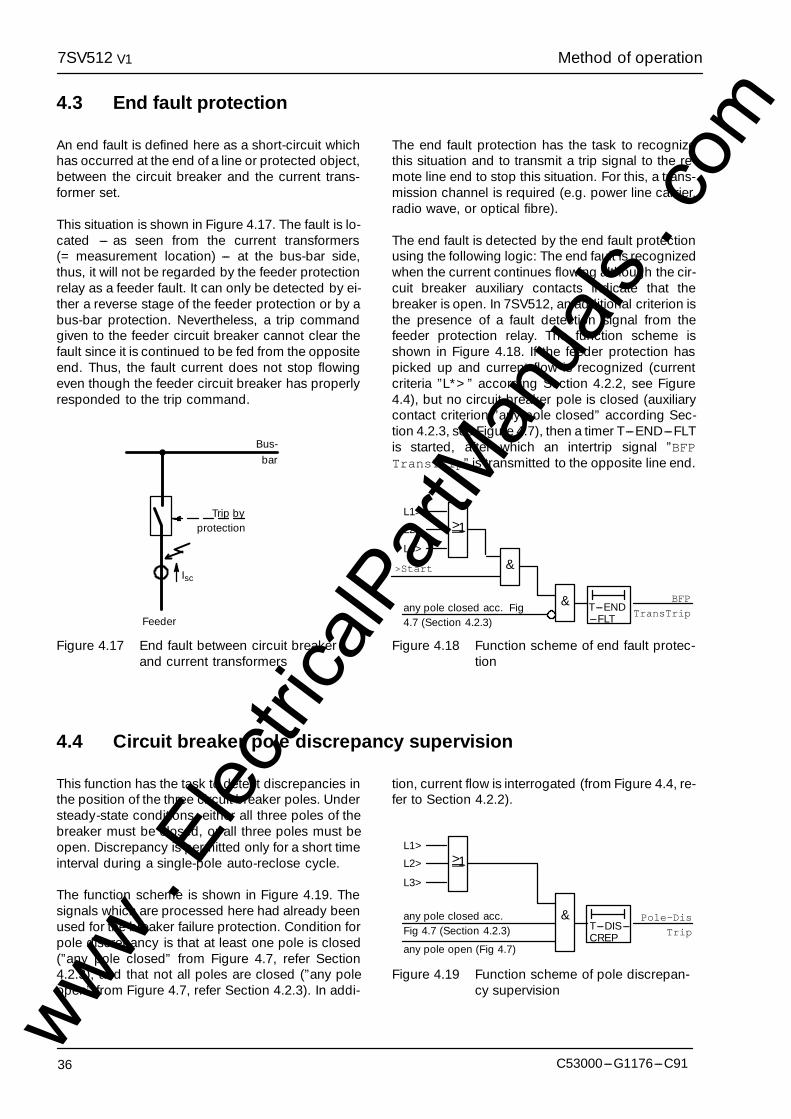
Method of operation7SV512 V1
36 C53000---G1176---C91
4.3 End fault protection
An end fault is defined here as a short-circuit whichhas occurred at the end of a line or protected object,between the circuit breaker and the current trans-former set.
This situation is shown in Figure 4.17. The fault is lo-cated --- as seen from the current transformers(= measurement location) --- at the bus-bar side,thus, it will not be regarded by the feeder protectionrelay as a feeder fault. It can only be detected by ei-ther a reverse stage of the feeder protection or by abus-bar protection. Nevertheless, a trip commandgiven to the feeder circuit breaker cannot clear thefault since it is continued to be fed from the oppositeend. Thus, the fault current does not stop flowingeven though the feeder circuit breaker has properlyresponded to the trip command.
Trip byprotection
Feeder
Bus-bar
Isc
Figure 4.17 End fault between circuit breakerand current transformers
The end fault protection has the task to recognizethis situation and to transmit a trip signal to the re-mote line end to stop this situation. For this, a trans-mission channel is required (e.g. power line carrier,radio wave, or optical fibre).
The end fault is detected by the end fault protectionusing the following logic: The end fault is recognizedwhen the current continues flowing although the cir-cuit breaker auxiliary contacts indicate that thebreaker is open. In 7SV512, an additional criterion isthe presence of a fault detection signal from thefeeder protection relay. The function scheme isshown in Figure 4.18. If the feeder protection haspicked up and current flow is recognized (currentcriteria ”L*>” according Section 4.2.2, see Figure4.4), but no circuit breaker pole is closed (auxiliarycontact criterion ”any pole closed” according Sec-tion 4.2.3, see Figure 4.7), then a timer T---END---FLTis started, after which an intertrip signal ”BFPTransTrip” is transmitted to the opposite line end.
& T---END---FLT
>Start
BFP
TransTrip
>1
&
L2>
L1>
L3>
any pole closed acc. Fig4.7 (Section 4.2.3)
Figure 4.18 Function scheme of end fault protec-tion
4.4 Circuit breaker pole discrepancy supervision
This function has the task to detect discrepancies inthe position of the three circuit breaker poles. Understeady-state conditions, either all three poles of thebreaker must be closed, or all three poles must beopen. Discrepancy is permitted only for a short timeinterval during a single-pole auto-reclose cycle.
The function scheme is shown in Figure 4.19. Thesignals which are processed here had already beenused for the breaker failure protection. Condition forpole discrepancy is that at least one pole is closed(”any pole closed” from Figure 4.7, refer Section4.2.3), and that not all poles are closed (”any poleopen” from Figure 4.7, refer Section 4.2.3). In addi-
tion, current flow is interrogated (from Figure 4.4, re-fer to Section 4.2.2).
&T---DIS---CREP
Pole-Dis
Trip
>1L2>
L1>
L3>
any pole closed acc.Fig 4.7 (Section 4.2.3)
any pole open (Fig 4.7)
Figure 4.19 Function scheme of pole discrepan-cy supervision
www . El
ectric
alPar
tMan
uals
. com
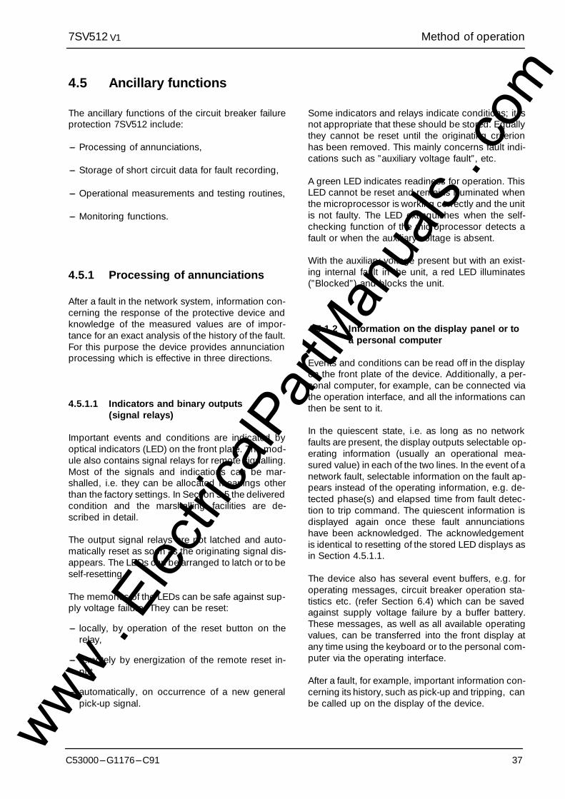
Method of operation7SV512 V1
37C53000---G1176---C91
4.5 Ancillary functions
The ancillary functions of the circuit breaker failureprotection 7SV512 include:
--- Processing of annunciations,
--- Storage of short circuit data for fault recording,
--- Operational measurements and testing routines,
--- Monitoring functions.
4.5.1 Processing of annunciations
After a fault in the network system, information con-cerning the response of the protective device andknowledge of the measured values are of impor-tance for an exact analysis of the history of the fault.For this purpose the device provides annunciationprocessing which is effective in three directions.
4.5.1.1 Indicators and binary outputs(signal relays)
Important events and conditions are indicated byoptical indicators (LED) on the front plate. The mod-ule also contains signal relays for remote signalling.Most of the signals and indications can be mar-shalled, i.e. they can be allocated meanings otherthan the factory settings. In Section 5.5 the deliveredcondition and the marshalling facilities are de-scribed in detail.
The output signal relays are not latched and auto-matically reset as soon as the originating signal dis-appears. The LEDs can be arranged to latch or to beself-resetting.
The memories of the LEDs can be safe against sup-ply voltage failure. They can be reset:
--- locally, by operation of the reset button on therelay,
--- remotely by energization of the remote reset in-put,
--- automatically, on occurrence of a new generalpick-up signal.
Some indicators and relays indicate conditions; it isnot appropriate that these should be stored. Equallythey cannot be reset until the originating criterionhas been removed. This mainly concerns fault indi-cations such as ”auxiliary voltage fault”, etc.
A green LED indicates readiness for operation. ThisLED cannot be reset and remains illuminated whenthe microprocessor is working correctly and the unitis not faulty. The LED extinguishes when the self-checking function of the microprocessor detects afault or when the auxiliary voltage is absent.
With the auxiliary voltage present but with an exist-ing internal fault in the unit, a red LED illuminates(”Blocked”) and blocks the unit.
4.5.1.2 Information on the display panel or toa personal computer
Events and conditions can be read off in the displayon the front plate of the device. Additionally, a per-sonal computer, for example, can be connected viathe operation interface, and all the informations canthen be sent to it.
In the quiescent state, i.e. as long as no networkfaults are present, the display outputs selectable op-erating information (usually an operational mea-sured value) in each of the two lines. In the event of anetwork fault, selectable information on the fault ap-pears instead of the operating information, e.g. de-tected phase(s) and elapsed time from fault detec-tion to trip command. The quiescent information isdisplayed again once these fault annunciationshave been acknowledged. The acknowledgementis identical to resetting of the stored LED displays asin Section 4.5.1.1.
The device also has several event buffers, e.g. foroperating messages, circuit breaker operation sta-tistics etc. (refer Section 6.4) which can be savedagainst supply voltage failure by a buffer battery.These messages, as well as all available operatingvalues, can be transferred into the front display atany time using the keyboard or to the personal com-puter via the operating interface.
After a fault, for example, important information con-cerning its history, such as pick-up and tripping, canbe called up on the display of the device.
www . El
ectric
alPar
tMan
uals
. com

Method of operation7SV512 V1
38 C53000---G1176---C91
The fault inception is indicated with the absolutetime of the operating system. The sequence of theevents is tagged with the relative time referred to themoment at which the fault detector has picked up.Thus, the elapsed time until tripping is initiated anduntil the trip signal is reset can be read out. The reso-lution is 1 ms.
The events can also be read out with a personalcomputer by means of the appropriate programDIGSI�. This provides the comfort of a CRT screenand menu-guided operation. Additionally, the datacan be documented on a printer or stored on afloppy disc for evaluation elsewhere.
The protection device stores the data of the lastthree network faults; if a fourth fault occurs the oldestfault is overwritten in the fault memory.
A network fault begins with recognition of the fault bypick-up and ends with fault detector reset.
4.5.1.3 Information to a central unit (optional)
All stored information can be transmitted via an opti-cal fibre connector (optional) to a control centre, forexample, the SIEMENS Localized Substation Auto-mation System LSA 678. Transmission uses a stan-dardized transmission protocol according to DIN19244.
4.5.2 Data storage and transmissionfor fault recording
The instantaneous values of the measured values
iL1, iL2, iL3, iE
are sampled at 1 ms intervals (for 50 Hz) and storedin a circulating shift register. In case of a fault, thedata from 5 cycles before the occurrence of the faultup until 5 cycles after the end of the network fault arestored, max. over 3 seconds. These data are thenavailable for fault analysis. For each renewed net-work fault, the actual new fault data are stored with-out acknowledgement of the old data.
The data can be transferred to a connected personalcomputer via the operation interface at the front andevaluated by the protection data evaluation programDIGSI�. The currents are referred to their maximumvalues, normalized to their rated values and pre-pared for graphic visualization. In addition, the sig-nals ”Pick-up”, ”Trip” and ”Drop-off” are marked onthe fault record.
Alternatively, the fault record data can be trans-mitted to a control centre via the serial interface (iffitted). In this case data are stored from 3 periods be-fore to 30 periods after pick-up of the device. Evalua-tion of the data is made in the control centre, usingappropriate software programs. The currents are re-ferred to their maximum values, normalized to theirrated values and prepared for graphic visualization.In addition, the signals ”Pick-up”, ”Trip” and ”Drop-off” are marked on the fault record.
When the data are transferred to a central unit, read-out can proceed automatically, optionally after eachpick-up of the relay or after an instantaneous trip.The following then applies:
--- The relay signals the availability of fault recorddata,
--- The data remain available for recall until com-mencement of the next fault event.
--- A transmission in progress can be aborted by thecentral unit.
4.5.3 Operating measurements andconversion
For local recall or transmission of data, the true rmsvalues of the measured currents are always avail-able.
The following is valid:
--- IL1, IL2, IL3 Phase currents in amps primary andin % of rated current
--- IE Earth current in amps primary andin % of rated current
www . El
ectric
alPar
tMan
uals
. com

Method of operation7SV512 V1
39C53000---G1176---C91
4.5.4 Monitoring functions
The device incorporates comprehensive monitoringfunctions which cover both hardware and software;furthermore, the measured values are continuouslychecked for plausibility so that the current trans-former circuits are also included in the monitoringsystem.
4.5.4.1 Hardware monitoring
Because of the high safety demand for the breakerfailure protection, a special hardware trip releasemodule is incorporated in 7SV512. This is describedin conjunction with the breaker failure protectionfunction in Section 4.2.7. In addition, the generalmonitoring functions of numerical protection andautomation relays are present:
The complete hardware is monitored for faults andinadmissible functions, from the measured value in-puts to the output relays. In detail this is accom-plished by monitoring:
--- Auxiliary and reference voltages
The processor monitors the offset and referencevoltage of the ADC (analog/digital converter). Theprotection is blocked as soon as impermissibledeviations occur. Permanent faults are annun-ciated.
Failure or switch-off of the auxiliary voltage auto-matically puts the system out of operation; thisstatus is indicated by a fail-safe contact. Transientdips in supply voltage of less than 50 ms will notdisturb the function of the relay.
--- Measured value acquisition
The complete chain, from the input transformersup to and including the analog/digital convertersare monitored by the plausibility check of themeasured values.
In the current path, there are four input conver-ters; the digitized sum of the outputs of thesemust always be zero. A fault in the current path isrecognized when
|iL1 + iL2 + iL3 + kI x iE| ²
SUM.Ithres x IN + SUM.Fact.I x Imax
An adjustable factor kI (parameter Ie/Iph) can beset to correct the different ratios of phase andearth current transformers (e.g. summation trans-former). If the residual earth current is derivedfrom the current transformer starpoint, kI = 1.SUM.Ithres and SUM.Fact.I are setting parame-ters (refer to Section 6.3.6). The componentSUM.Fact.I x Imax takes into account permissiblecurrent proportional transformation errors in theinput converters which may particularly occur un-der conditions of high short circuit currents (Fig-ure 4.20).
Note: Current sum monitoring can operate prop-erly only when the residual current of the pro-tected object is fed to the IE input of the relay.
ImaxIN
IFIN
IF = Fault current
SUM.Ithres
Slope:SUM.Fact.I
Figure 4.20 Current sum monitoring (currentplausibility check)
--- Command output channels:
The command relays for tripping are controlled bytwo command and one additional release chan-nels. As long as no pick-up condition exists, thecentral processor makes a cyclic check of thesecommand output channel for availability, by excit-ing each channel one after the other and check-ing for change in the output signal level. Changeof the feed-back signal to low level indicates afault in one of the control channels or in the relaycoil. Such a condition leads automatically toalarm and blocking of the command output. In ad-dition, a trip release module as described in Sec-tion 4.2.7 is effective for trip relays K1 and K2.
--- Memory modules:
The memory modules are periodically checkedfor fault by:
D Writing a data bit pattern for the workingmemory (RAM) and reading it,www .
Elec
tricalP
artM
anua
ls . c
om
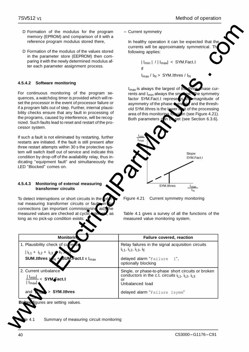
Method of operation7SV512 V1
40 C53000---G1176---C91
D Formation of the modulus for the programmemory (EPROM) and comparison of it with areference program modulus stored there,
D Formation of the modulus of the values storedin the parameter store (EEPROM) then com-paring it with the newly determined modulus af-ter each parameter assignment process.
4.5.4.2 Software monitoring
For continuous monitoring of the program se-quences, a watchdog timer is provided which will re-set the processor in the event of processor failure orif a program falls out of step. Further, internal plausi-bility checks ensure that any fault in processing ofthe programs, caused by interference, will be recog-nized. Such faults lead to reset and restart of the pro-cessor system.
If such a fault is not eliminated by restarting, furtherrestarts are initiated. If the fault is still present afterthree restart attempts within 30 s the protective sys-tem will switch itself out of service and indicate thiscondition by drop-off of the availability relay, thus in-dicating ”equipment fault” and simultaneously theLED ”Blocked” comes on.
4.5.4.3 Monitoring of external measuringtransformer circuits
To detect interruptions or short circuits in the exter-nal measuring transformer circuits or faults in theconnections (an important commissioning aid) themeasured values are checked at cyclic intervals, aslong as no pick-up condition exists:
--- Current symmetry
In healthy operation it can be expected that thecurrents will be approximately symmetrical. Thefollowing applies:
|Imin | / |Imax| < SYM.Fact.I
if
Imax / IN > SYM.Ithres / IN
Imax is always the largest of the three phase cur-rents and Imin always the smallest. The symmetryfactor SYM.Fact.I represents the magnitude ofasymmetry of the phase currents, and the thresh-old SYM.Ithres is the lower limit of the processingarea of this monitoring function (see Figure 4.21).Both parameters can be set (see Section 6.3.6).
SYM.Ithres
Slope:SYM.Fact.I
IminImax
ImaxIN
Figure 4.21 Current symmetry monitoring
Table 4.1 gives a survey of all the functions of themeasured value monitoring system.
< SYM.Fact.I
and |Imax| > SYM.Ithres
|Imax||Imin|
Relay failures in the signal acquisition circuits
delayed alarm ”Failure �I”,optionally blocking
1. Plausibility check of currents
|iL1 + iL2 + iL3 + kI x iE| ²
SUM.Ithres x IN + SUM.Fact.I x Imax
2. Current unbalance
iL1, iL2, iL3, iE
Single, or phase-to-phase short circuits or brokenconductors in the c.t. circuits iL1, iL2, iL3orUnbalanced load
delayed alarm ”Failure Isymm”
Monitoring Failure covered, reaction
Bolted figures are setting values.
Table 4.1 Summary of measuring circuit monitoringwww . El
ectric
alPar
tMan
uals
. com

7SV512 Installation instructionsV1
41C53000---G1176---C91
5 Installation instructions
! WarningThe successful and safe operation of this device is dependent on proper handling and installationby qualified personnel under observance of all warnings and hints contained in this manual.
In particular the general erection and safety regulations (e.g. IEC, DIN, VDE, or national standards)regarding the correct use of hoisting gear must be observed. Non-observance can result in death,personal injury or substantial property damage.
5.1 Unpacking and repacking
When dispatched from the factory, the equipment ispacked in accordance with the guidelines laid downin IEC 60255---21, which specifies the impact resis-tance of packaging.
This packing shall be removed with care, withoutforce and without the use of inappropriate tools. Theequipment should be visually checked to ensurethat there are no external traces of damage.
The transport packing can be re-used for furthertransport when applied in the same way. The stor-age packing of the individual relays is not suited totransport. If alternative packing is used, this mustalso provide the same degree of protection againstmechanical shock, as laid down in IEC 60255---21---1 class 2 and IEC 60255---21---2 class 1.
Before initial energization with supply voltage, therelay shall be situated in the operating area for atleast two hours in order to ensure temperatureequalization and to avoid humidity influences andcondensation.
5.2 Preparations
The operating conditions must accord with VDE0100/5.73 and VDE 0105 part 1/7.83, or correspond-ing national standards for electrical power installa-tions.
The modules of digital relays containCMOS circuits. These shall not be with-drawn or inserted under live conditions!The modules must be so handled that anypossibility of damage due to static electri-cal charges is excluded. During any neces-sary handling of individual modules the re-commendations relating to the handling ofelectrostatically endangered components(EEC) must be observed.
! Caution!
In installed conditions, the modules are in no dan-ger.
www . El
ectric
alPar
tMan
uals
. com
Installation instructions7SV512 V1
42 C53000---G1176---C91
5.2.1 Mounting and connections
5.2.1.1 Model 7SV512K---KBKKK for panel sur-face mounting
--- Secure the unit with four screws to the panel. Forthe dimensions refer to Figure 2.2.
--- Connect the earthing terminal (Terminal 16) of theunit to the protective earth of the panel.
--- Make a solid low-ohmic and low-inductance op-erational earth connection between the earthingsurface at the side of the unit using at least onestandard screw M4, and the earthing continuitysystem of the panel; recommended groundingstrap DIN 72333 form A, e.g. Order-No. 15284 ofMessrs Druseidt, Remscheid, Germany.
--- Make connections via screwed terminals.
5.2.1.2 Model 7SV512K---KCKKK for panel flushmounting or cubicle installation
--- Lift up both labelling strips on the lid of the unitand remove cover to gain access to the four holesfor the fixing screws.
--- Insert the unit into the panel cut-out and secure itwith the fixing screws. For the dimensions refer toFigure 2.3.
--- Connect the earthing screw on the rear of the unitto the protective earth of the panel or cubicle.
--- Make a solid low-ohmic and low-inductance op-erational earth connection between the earthingsurface at the rear of the unit using at least onestandard screw M4, and the earthing continuitysystem of the panel or cubicle; recommendedgrounding strap DIN 72333 form A, e.g. Order-No. 15284 of Messrs Druseidt, Remscheid, Ger-many.
--- Make connections via the screwed or snap-in ter-minals of the sockets of the housing. Observe la-belling of the individual connector modules to en-sure correct location; observe the max. permissi-ble conductor cross-sections. The use of thescrewed terminals is recommended; snap-in con-nection requires special tools and must not beused for field wiring unless proper strain relief andthe permissible bending radius are observed.
5.2.2 Checking the rated data
The rated data of the unit must be checked againstthe plant data. This applies in particular to the ratedcurrent of the current transformers and rated d.c.voltage of the substation battery.
5.2.2.1 Control d.c. voltage of binary inputs
When delivered from the factory, the binary inputsare designed to operate in the total control voltagerange from 19 V to 288 V. If the rated control voltagefor the binary inputs is 110 V or higher, it is advisableto select a higher pick-up threshold to these inputsto increase stability against stray voltages in the d.c.circuits.
To select a higher pick-up threshold of approximate-ly 80 V for a binary input a solder bridge must be re-moved. Figure 5.1 shows the allocation of these sol-der bridges for the inputs BI 1 and BI 2, and their lo-cation on the basic p.c.b. (EPS) of the module. Fig-ure 5.2 shows the assignment of these solderbridges for the inputs BI 3 to BI 10 and their locationon the additional p.c.b. (EAZ---2).
--- Open housing cover.
--- Loosen the module using the pulling aids pro-vided at the top and bottom.
Electrostatic discharges via the compo-nent connections, the PCB tracks or theconnecting pins of the modules must beavoided under all circumstances by pre-viously touching an earthed metal sur-face.
! Caution!
--- Pull out module and place onto a conductive sur-face.
--- Check the solder bridges according to Figure 5.1and 5.2, remove bridges where necessary.
--- Insert module into the housing; ensure that the re-leasing lever is pushed fully to the right before themodule is pressed in.
--- Firmly push in the module using the releasing le-ver.
--- Close housing cover.
www . El
ectric
alPar
tMan
uals
. com
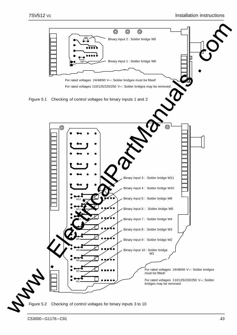
7SV512 Installation instructionsV1
43C53000---G1176---C91
Binary input 2 : Solder bridge W5
Binary input 1 : Solder bridge W6
For rated voltages 24/48/60 V---: Solder bridges must be fitted!
For rated voltages 110/125/220/250 V---: Solder bridges may be removed.
W5
W6
Figure 5.1 Checking of control voltages for binary inputs 1 and 2
Binary input 3 : Solder bridge W11
Binary input 4 : Solder bridge W10
Binary input 5 : Solder bridge W6
Binary input 6 : Solder bridge W5
Binary input 7 : Solder bridge W4
Binary input 8 : Solder bridge W3
Binary input 9 : Solder bridge W2
Binary input 10 : Solder bridgeW1
W1
W2
W3
W4
W5
W6
W10
W11
W12
For rated voltages 24/48/60 V---: Solder bridgesmust be fitted!
For rated voltages 110/125/220/250 V---: Solderbridges may be removed.
Figure 5.2 Checking of control voltages for binary inputs 3 to 10www . El
ectric
alPar
tMan
uals
. com
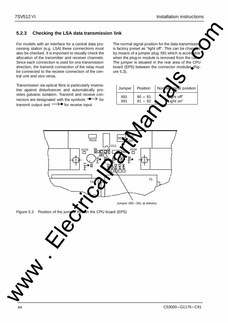
Installation instructions7SV512 V1
44 C53000---G1176---C91
5.2.3 Checking the LSA data transmission link
For models with an interface for a central data pro-cessing station (e.g. LSA) these connections mustalso be checked. It is important to visually check theallocation of the transmitter and receiver channels.Since each connection is used for one transmissiondirection, the transmit connection of the relay mustbe connected to the receive connection of the cen-tral unit and vice versa.
Transmission via optical fibre is particularly insensi-tive against disturbances and automatically pro-vides galvanic isolation. Transmit and receive con-nectors are designated with the symbols fortransmit output and for receive input.
The normal signal position for the data transmissionis factory preset as ”light off”. This can be changedby means of a jumper plug X91 which is accessiblewhen the plug-in module is removed from the case.The jumper is situated in the rear area of the CPUboard (EPS) between the connector modules (Fig-ure 5.3).
Jumper Position Normal signal position
X91 90 --- 91 ”Light off”X91 91 --- 92 ”Light on”
R124V 40V39
X104R94
X91
D11X103
+
T4T3
Jumper X90---X91 at delivery
Figure 5.3 Position of the jumper X91 on the CPU board (EPS)
www . El
ectric
alPar
tMan
uals
. com
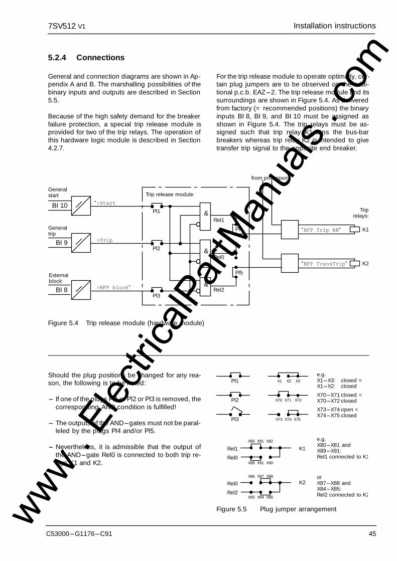
7SV512 Installation instructionsV1
45C53000---G1176---C91
5.2.4 Connections
General and connection diagrams are shown in Ap-pendix A and B. The marshalling possibilities of thebinary inputs and outputs are described in Section5.5.
Because of the high safety demand for the breakerfailure protection, a special trip release module isprovided for two of the trip relays. The operation ofthis hardware logic module is described in Section4.2.7.
For the trip release module to operate optimally, cer-tain plug jumpers are to be observed on the addi-tional p.c.b. EAZ---2. The trip release module and itssurroundings are shown in Figure 5.4. As deliveredfrom factory (= recommended positions) the binaryinputs BI 8, BI 9, and BI 10 must be assigned asshown in Figure 5.4. The trip relays must be as-signed such that trip relay K1 trips the bus-barbreakers whereas trip relay K2 is intended to givetransfer trip signal to the opposite end breaker.
BI 9
Generaltrip
BI 10
Pl5
Pl4
”BFP TransTrip”
BI 8
Trip release module
&
&
&
Pl1
from processor
K1
Generalstart
Externalblock
Rel1
Rel0
Rel2
Pl2
Pl3
Triprelays:
K2
”>Start
>Trip
>BFP block”
”BFP Trip BB”
Figure 5.4 Trip release module (hardware module)
Should the plug positions be changed for any rea-son, the following is to be noted:
--- If one of the plugs Pl1 or Pl2 or Pl3 is removed, thecorresponding AND condition is fulfilled!
--- The outputs of the AND---gates must not be paral-leled by the plugs Pl4 and/or Pl5.
--- Nevertheless, it is admissible that the output ofthe AND---gate Rel0 is connected to both trip re-lays K1 and K2.
Pl1 X1 X2 X3
Pl2 X70 X71 X72
Pl3 X73 X74 X75
e.g.X1---X3: closed =X1---X2: closed
X70---X71 closed =X70---X72 closed
X73---X74 open =X74---X75 closed
X80 X81 X82
X89 X91 X90
Rel1
Rel0
K1
X86 X87 X88
X83 X84 X85
Rel0
Rel2
K2
e.g.X80---X81 andX89---X91:Rel1 connected to K1
orX87---X88 andX84---X85:Rel2 connected to K2
�
�
�
Figure 5.5 Plug jumper arrangementwww . El
ectric
alPar
tMan
uals
. com

Installation instructions7SV512 V1
46 C53000---G1176---C91
--- And, of course:
Electrostatic discharges via the compo-nent connections, the PCB tracks or theconnecting pins of the modules must beavoided under all circumstances by pre-viously touching an earthed metal sur-face.
! Caution!
The plug jumpers are arranged as shown in Figure5.6. Figure 5.5 shows the mechanical and electricalarrangement and is intended as translation betweenFigure 5.4 and 5.6.
SIEMENSEAZ2
C73040---A51---C138
X 1 X 2 X 3X70 X71 X72X73 X74 X75X82 X81 X80X90 X91 X89X88 X87 X86X85 X84 X83
W1
W2
W17
W1W7W8W9
W16W18W19
W14
W13
Figure 5.6 Position of the solder bridges W7 to W9 and W16 to W19 on the additional board(EAZ---2)
www . El
ectric
alPar
tMan
uals
. com
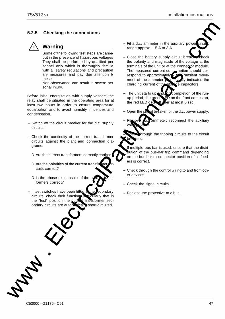
7SV512 Installation instructionsV1
47C53000---G1176---C91
5.2.5 Checking the connections
! WarningSome of the following test steps are carriedout in the presence of hazardous voltages.They shall be performed by qualified personnel only which is thoroughly familiawith all safety regulations and precaution-ary measures and pay due attention tothese.Non-observance can result in severe personal injury.
Before initial energization with supply voltage, therelay shall be situated in the operating area for atleast two hours in order to ensure temperatureequalization and to avoid humidity influences andcondensation.
--- Switch off the circuit breaker for the d.c. supplycircuits!
--- Check the continuity of the current transformercircuits against the plant and connection dia-grams:
D Are the current transformers correctly earthed?
D Are the polarities of the current transformer cir-cuits correct?
D Is the phase relationship of the current trans-formers correct?
--- If test switches have been fitted in the secondarycircuits, check their function, particularly that inthe ”test” position the current transformer sec-ondary circuits are automatically short-circuited.
--- Fit a d.c. ammeter in the auxiliary power circuit;range approx. 1.5 A to 3 A.
--- Close the battery supply circuit breaker; checkthe polarity and magnitude of the voltage at theterminals of the unit or at the connector module.
--- The measured current consumption should cor-respond to approximately 7 W. Transient move-ment of the ammeter pointer only indicates thecharging current of the storage capacitors.
--- The unit starts up and, on completion of the run-up period, the green LED on the front comes on,the red LED gets off after at most 5 sec.
--- Open the circuit breaker for the d.c. power supply.
--- Remove d.c. ammeter; reconnect the auxiliaryvoltage leads.
--- Check through the tripping circuits to the circuitbreakers.
--- If multiple bus-bar is used, ensure that the distri-bution of the bus-bar trip command dependingon the bus-bar disconnector position of all feed-ers is correct.
--- Check through the control wiring to and from oth-er devices.
--- Check the signal circuits.
--- Reclose the protective m.c.b.’s.
www . El
ectric
alPar
tMan
uals
. com
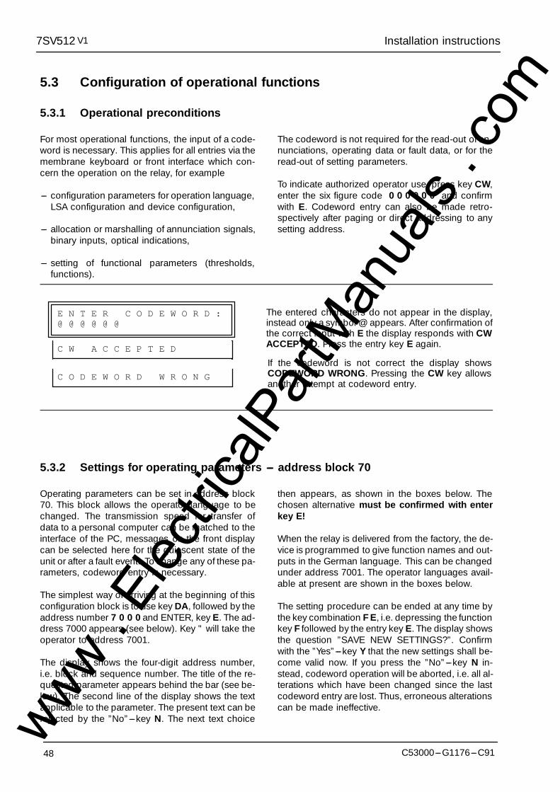
Installation instructions7SV512 V1
48 C53000---G1176---C91
5.3 Configuration of operational functions
5.3.1 Operational preconditions
For most operational functions, the input of a code-word is necessary. This applies for all entries via themembrane keyboard or front interface which con-cern the operation on the relay, for example
--- configuration parameters for operation language,LSA configuration and device configuration,
--- allocation or marshalling of annunciation signals,binary inputs, optical indications,
--- setting of functional parameters (thresholds,functions).
The codeword is not required for the read-out of an-nunciations, operating data or fault data, or for theread-out of setting parameters.
To indicate authorized operator use, press key CW,enter the six figure code 0 0 0 0 0 0 and confirmwith E. Codeword entry can also be made retro-spectively after paging or direct addressing to anysetting address.
E N T E R C O D E W O R D :@ @ @ @ @ @
C W A C C E P T E D
C O D E W O R D W R O N G
The entered characters do not appear in the display,instead only a symbol @ appears. After confirmation ofthe correct input with E the display responds with CWACCEPTED. Press the entry key E again.
If the codeword is not correct the display showsCODEWORD WRONG. Pressing the CW key allowsanother attempt at codeword entry.
5.3.2 Settings for operating parameters --- address block 70
Operating parameters can be set in address block70. This block allows the operator language to bechanged. The transmission speed for transfer ofdata to a personal computer can be matched to theinterface of the PC, messages on the front displaycan be selected here for the quiescent state of theunit or after a fault event. To change any of these pa-rameters, codeword entry is necessary.
The simplest way of arriving at the beginning of thisconfiguration block is to use key DA, followed by theaddress number 7 0 0 0 and ENTER, key E. The ad-dress 7000 appears (see below). Key " will take theoperator to address 7001.
The display shows the four-digit address number,i.e. block and sequence number. The title of the re-quested parameter appears behind the bar (see be-low). The second line of the display shows the textapplicable to the parameter. The present text can berejected by the ”No”---key N. The next text choice
then appears, as shown in the boxes below. Thechosen alternative must be confirmed with enterkey E!
When the relay is delivered from the factory, the de-vice is programmed to give function names and out-puts in the German language. This can be changedunder address 7001. The operator languages avail-able at present are shown in the boxes below.
The setting procedure can be ended at any time bythe key combination F E, i.e. depressing the functionkey F followed by the entry key E. The display showsthe question ”SAVE NEW SETTINGS?”. Confirmwith the ”Yes”---key Y that the new settings shall be-come valid now. If you press the ”No”---key N in-stead, codeword operation will be aborted, i.e. all al-terations which have been changed since the lastcodeword entry are lost. Thus, erroneous alterationscan be made ineffective.www .
Elec
tricalP
artM
anua
ls . c
om
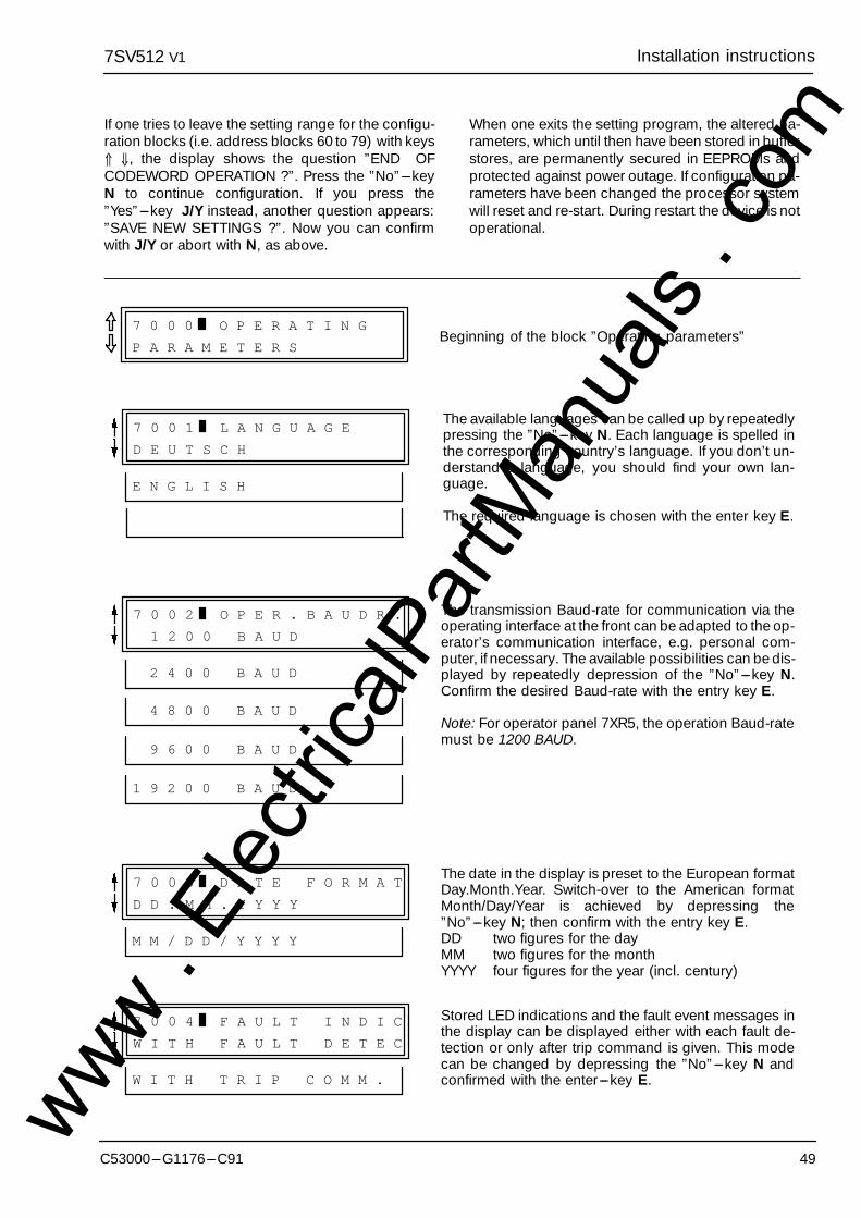
7SV512 Installation instructionsV1
49C53000---G1176---C91
If one tries to leave the setting range for the configu-ration blocks (i.e. address blocks 60 to 79) with keys⇑ ⇓, the display shows the question ”END OFCODEWORD OPERATION ?”. Press the ”No”---keyN to continue configuration. If you press the”Yes”---key J/Y instead, another question appears:”SAVE NEW SETTINGS ?”. Now you can confirmwith J/Y or abort with N, as above.
When one exits the setting program, the altered pa-rameters, which until then have been stored in bufferstores, are permanently secured in EEPROMs andprotected against power outage. If configuration pa-rameters have been changed the processor systemwill reset and re-start. During restart the device is notoperational.
7 0 0 0 O P E R A T I N G
P A R A M E T E R SBeginning of the block ”Operating parameters”
7 0 0 1 L A N G U A G E
D E U T S C H
E N G L I S H
The available languages can be called up by repeatedlypressing the ”No”---key N. Each language is spelled inthe corresponding country’s language. If you don’t un-derstand a language, you should find your own lan-guage.
The required language is chosen with the enter key E.
7 0 0 2 O P E R . B A U D R .
1 2 0 0 B A U D
The transmission Baud-rate for communication via theoperating interface at the front can be adapted to the op-erator’s communication interface, e.g. personal com-puter, if necessary. The available possibilities can be dis-played by repeatedly depression of the ”No”---key N.Confirm the desired Baud-rate with the entry key E.
Note: For operator panel 7XR5, the operation Baud-ratemust be 1200 BAUD.
2 4 0 0 B A U D
4 8 0 0 B A U D
9 6 0 0 B A U D
1 9 2 0 0 B A U D
7 0 0 3 D A T E F O R M A T
D D . M M . Y Y Y Y
The date in the display is preset to the European formatDay.Month.Year. Switch-over to the American formatMonth/Day/Year is achieved by depressing the”No”---key N; then confirm with the entry key E.DD two figures for the dayMM two figures for the monthYYYY four figures for the year (incl. century)
M M / D D / Y Y Y Y
7 0 0 4 F A U L T I N D I C
W I T H F A U L T D E T E C
Stored LED indications and the fault event messages inthe display can be displayed either with each fault de-tection or only after trip command is given. This modecan be changed by depressing the ”No”---key N andconfirmed with the enter---key E.W I T H T R I P C O M M .
www . El
ectric
alPar
tMan
uals
. com
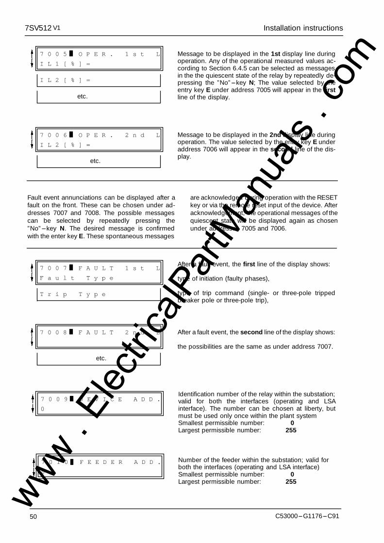
Installation instructions7SV512 V1
50 C53000---G1176---C91
7 0 0 5 O P E R . 1 s t L
I L 1 [ % ] =
Message to be displayed in the 1st display line duringoperation. Any of the operational measured values ac-cording to Section 6.4.5 can be selected as messagesin the the quiescent state of the relay by repeatedly de-pressing the ”No”---key N; The value selected by theentry key E under address 7005 will appear in the firstline of the display.
I L 2 [ % ] =
etc.
7 0 0 6 O P E R . 2 n d L
I L 2 [ % ] =
Message to be displayed in the 2nd display line duringoperation. The value selected by the entry key E underaddress 7006 will appear in the second line of the dis-play.
etc.
Fault event annunciations can be displayed after afault on the front. These can be chosen under ad-dresses 7007 and 7008. The possible messagescan be selected by repeatedly pressing the”No”---key N. The desired message is confirmedwith the enter key E. These spontaneous messages
are acknowledged during operation with the RESETkey or via the remote reset input of the device. Afteracknowledgement, the operational messages of thequiescent state will be displayed again as chosenunder addresses 7005 and 7006.
7 0 0 7 F A U L T 1 s t L
F a u l t T y p e
After a fault event, the first line of the display shows:
type of initiation (faulty phases),
type of trip command (single- or three-pole trippedbreaker pole or three-pole trip),
T r i p T y p e
7 0 0 8 F A U L T 2 n d L After a fault event, the second line of the display shows:
the possibilities are the same as under address 7007.
etc.
7 0 0 9 D E V I C E A D D .
0
Identification number of the relay within the substation;valid for both the interfaces (operating and LSAinterface). The number can be chosen at liberty, butmust be used only once within the plant systemSmallest permissible number: 0Largest permissible number: 255
7 0 1 0 F E E D E R A D D .
0
Number of the feeder within the substation; valid forboth the interfaces (operating and LSA interface)Smallest permissible number: 0Largest permissible number: 255
www . El
ectric
alPar
tMan
uals
. com
7SV512 Installation instructionsV1
51C53000---G1176---C91
5.4 Configuration of the device functions
5.4.1 Introduction
The device 7SV512 is capable of providing a seriesof functions. The scope of the hard- and firm-ware ismatched to these functions. Furthermore, individualfunctions can be set (configured) to be effective ornon-effective or the interaction of the functions canbe modified by configuration parameters. Addition-ally, the relay can be adapted to the system frequen-cy.
The configuration parameters are input through theintegrated operation keyboard at the front of the de-vice or by means of a personal computer, connectedto this front-interface. The use of the integrated oper-ating keyboard is described in detail in Section 6.2.Alteration of the programmed parameters requiresthe input of the codeword (see Section 5.3.1). With-out codeword, the setting can be read out but not al-tered.
For the purpose of configuration, addresses 78KKare provided. One can access the beginning of theconfiguration blocks either by direct dial
--- press direct address key DA,
--- type in address 7 8 0 0,
--- press execute key E ;
or by paging with the keys ⇑ (forwards) or ⇓ (back-wards), until address 7800 appears.
Within the bock 78 one can page forward with " orback with #. Each paging action leads to a furtheraddress for the input of a configuration parameter. Inthe following sections, each address is shown in abox and explained. In the upper line of the display,behind the number and the bar, stands the asso-
ciated device function. In the second line is the asso-ciated text (e.g. ”EXIST”). If this text is appropriatethe arrow keys " or # can be used to page the nextaddress. If the text should be altered press the”No”---key N; an alternative text then appears (e.g.”NON---EXIST”). There may be other alternativeswhich can then be displayed by repeated depres-sion of the ”No”---key N. The required alternativemust be confirmed with the key E!
The configuration procedure can be ended at anytime by the key combination F E, i.e. depressing thefunction key F followed by the entry key E. The dis-play shows the question ”SAVE NEW SETTINGS ?”.Confirm with the ”Yes”---key J/Y that the new set-tings shall become valid now. If you press the”No”---key N instead, codeword operation will beaborted, i.e. all alterations which have beenchanged since the last codeword entry are lost.Thus, erroneous alterations can be made ineffec-tive.
If one tries to leave the setting range for the configu-ration blocks (i.e. address blocks 60 to 79) with keys⇑ ⇓, the display shows the question ”END OF CODE-WORD OPERATION ?”. Press the ”No”---key N tocontinue configuration. If you press the ”Yes”---keyJ/Y instead, another question appears: ”SAVE NEWSETTINGS ?”. Now you can confirm with J/Y orabort with N, as described above.
When one exits the setting program, the altered pa-rameters, which until then have been stored in vola-tile memories, are then permanently secured inEEPROMs and protected against power outage.The processor system will reset and re-start. Duringre-start the device is not operational.
www . El
ectric
alPar
tMan
uals
. com

Installation instructions7SV512 V1
52 C53000---G1176---C91
5.4.2 Programming the scope of functions --- address block 78
The available functions can be programmed as ex-isting or not existing. For some functions it may alsobe possible to select between multiple alternatives.
Functions which are configured as NON EXIST willnot be processed in 7SV512: There will be no annun-ciations and the associated setting parameters(functions, limit values) will not be requested duringsetting (Section 6.3). In contrast, switch-off of a
function means that the function will be processed,that indication will appear (e.g. ”... switched off”) butthat the function will have no effect on the result ofthe protective process (e.g. no command).
The following boxes show the possibilities for themaximum scope of the device. In an actual case,functions which are not available will not appear inthe display.
7 8 0 0 S C O P E O F
F U N C T I O N SBeginning of the block ”scope of functions”
7 8 2 8 F A U L T R E C R D
E X I S T
N O N E X I S T
E X I S T
7 8 3 8 P O L E D I S C R P
N O N - E X I S T
E X I S T
7 8 6 9 L S A
N O N - E X I S T
E X I S T
7 8 8 5 P A R A M . C / O
N O N - E X I S T
The rated system frequency must comply with the setting under address 7899. If the system frequency is not50 Hz, address 7899 must be changed.
7 8 9 9 F R E Q U E N C Y
f N 5 0 H z
f N 6 0 H z
Rated system frequency 50 Hz or 60 Hz
www . El
ectric
alPar
tMan
uals
. com
7SV512 Installation instructionsV1
53C53000---G1176---C91
5.5 Marshalling of binary inputs, binary outputs and LED indicators
5.5.1 Introduction
The functions of the binary inputs and outputs repre-sented in the general diagrams (Appendix A) relateto the factory settings. The assignment of the inputsand outputs of the internal functions can be rear-ranged and thus adapted to the on-site conditions.
Marshalling of the inputs, outputs and LEDs is per-formed by means of the integrated operator panel orvia the operating interface in the front. The operationof the operator panel is described in detail in Section6.2. Marshalling begins at the parameter address6000.
The input of the codeword is required for marshal-ling (refer Section 5.3.1). Without codeword entry,parameters can be read out but not be changed.During codeword operation, i.e. from codewordentry until the termination of the configuration proce-dure, the solid bar in the display flashes.
When the firmware programs are running the specif-ic logic functions will be allocated to the physical in-put and output modules or LEDs in accordance withthe selection.
Example: A start signal is registered. This event isgenerated in the device as an ”Annunciation” (log-ical function) and should be available at certain ter-minals of the unit as a N.O. contact. Since specificunit terminals are hard-wired to a specific (physical)output relay, e.g. to the signal relay 1, the processormust be advised that the logical signal ”BFPStart” should be transmitted to the signal relay 1.Thus, when marshalling is performed two state-ments of the operator are important: Which (logical)annunciation generated in the protection unit pro-gram should trigger which (physical) output relay?Up to 20 logical annunciations can trigger one(physical) output relay.
A similar situation applies to binary inputs. In thiscase external information (e.g. ”Trip L1 by feederprotection”) is connected to the unit via a (physical)
input module and should initiate a (logical) function,namely start of the breaker failure protection. Thecorresponding question to the operator is then:Which signal from a (physical) input relay should ini-tiate which reaction in the device? One physical in-put signal can initiate up to 10 logical functions.
The trip relays can also be assigned different func-tions. Each trip relay can be controlled by each com-mand function or combination of command func-tions.
The logical annunciation functions can be used inmultiple manner. E.g. one annunciation function cantrigger several signal relays, several trip relays, addi-tionally be indicated by LEDs, and be controlled by abinary input unit. The restriction is, that the total of allphysical input/output units (binary inputs plus signalrelays plus LEDs plus trip relays) which are to be as-sociated with one logical function must not exceed anumber of 10. If this number is tried to be exceeded,the display will show a corresponding message.
The marshalling procedure is set up such that foreach (physical) binary input, each output relay, andfor each marshallable LED, the operator will beasked which (logical) function should be allocated.
The offered logical functions are tabulated for thebinary inputs, outputs and LEDs in the following sec-tions.
The beginning of the marshalling parameter blocksis reached by directly selecting the address 6000,i.e.
--- press direct address key DA,--- enter address 6 0 0 0,--- press enter key E
or by paging with keys ⇑ (forwards) or ⇓ (back-wards) until address 6000 has been reached. Thebeginning of the marshalling blocks then appears:
6 0 0 0
M A R S H A L L I N GBeginning of marshalling blocks
www . El
ectric
alPar
tMan
uals
. com
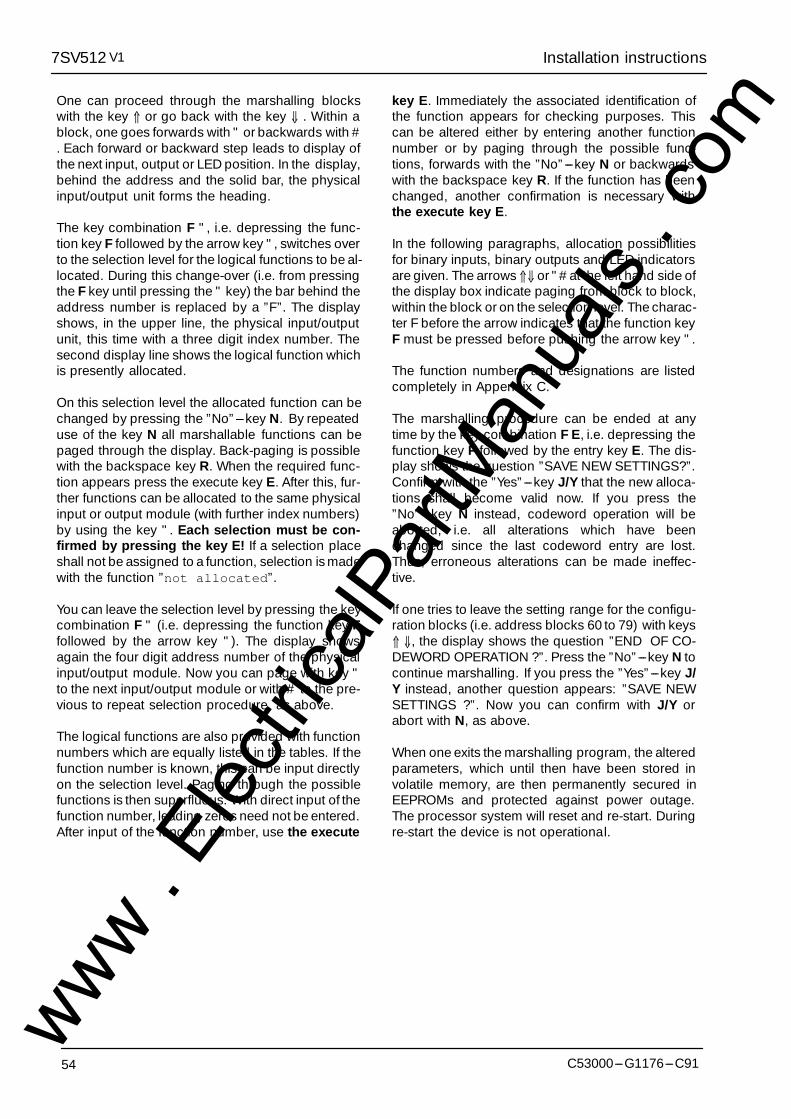
Installation instructions7SV512 V1
54 C53000---G1176---C91
One can proceed through the marshalling blockswith the key ⇑ or go back with the key ⇓ . Within ablock, one goes forwards with " or backwards with #. Each forward or backward step leads to display ofthe next input, output or LED position. In the display,behind the address and the solid bar, the physicalinput/output unit forms the heading.
The key combination F ", i.e. depressing the func-tion key F followed by the arrow key ", switches overto the selection level for the logical functions to be al-located. During this change-over (i.e. from pressingthe F key until pressing the " key) the bar behind theaddress number is replaced by a ”F”. The displayshows, in the upper line, the physical input/outputunit, this time with a three digit index number. Thesecond display line shows the logical function whichis presently allocated.
On this selection level the allocated function can bechanged by pressing the ”No”---key N. By repeateduse of the key N all marshallable functions can bepaged through the display. Back-paging is possiblewith the backspace key R. When the required func-tion appears press the execute key E. After this, fur-ther functions can be allocated to the same physicalinput or output module (with further index numbers)by using the key ". Each selection must be con-firmed by pressing the key E! If a selection placeshall not be assigned to a function, selection is madewith the function ”not allocated”.
You can leave the selection level by pressing the keycombination F " (i.e. depressing the function key Ffollowed by the arrow key "). The display showsagain the four digit address number of the physicalinput/output module. Now you can page with key "to the next input/output module or with # to the pre-vious to repeat selection procedure, as above.
The logical functions are also provided with functionnumbers which are equally listed in the tables. If thefunction number is known, this can be input directlyon the selection level. Paging through the possiblefunctions is then superfluous. With direct input of thefunction number, leading zeros need not be entered.After input of the function number, use the execute
key E. Immediately the associated identification ofthe function appears for checking purposes. Thiscan be altered either by entering another functionnumber or by paging through the possible func-tions, forwards with the ”No”---key N or backwardswith the backspace key R. If the function has beenchanged, another confirmation is necessary withthe execute key E.
In the following paragraphs, allocation possibilitiesfor binary inputs, binary outputs and LED indicatorsare given. The arrows ⇑⇓ or "# at the left hand side ofthe display box indicate paging from block to block,within the block or on the selection level. The charac-ter F before the arrow indicates that the function keyF must be pressed before pushing the arrow key ".
The function numbers and designations are listedcompletely in Appendix C.
The marshalling procedure can be ended at anytime by the key combination F E, i.e. depressing thefunction key F followed by the entry key E. The dis-play shows the question ”SAVE NEW SETTINGS?”.Confirm with the ”Yes”---key J/Y that the new alloca-tions shall become valid now. If you press the”No”---key N instead, codeword operation will beaborted, i.e. all alterations which have beenchanged since the last codeword entry are lost.Thus, erroneous alterations can be made ineffec-tive.
If one tries to leave the setting range for the configu-ration blocks (i.e. address blocks 60 to 79) with keys⇑ ⇓, the display shows the question ”END OF CO-DEWORD OPERATION ?”. Press the ”No”---key N tocontinue marshalling. If you press the ”Yes”---key J/Y instead, another question appears: ”SAVE NEWSETTINGS ?”. Now you can confirm with J/Y orabort with N, as above.
When one exits the marshalling program, the alteredparameters, which until then have been stored involatile memory, are then permanently secured inEEPROMs and protected against power outage.The processor system will reset and re-start. Duringre-start the device is not operational.
www . El
ectric
alPar
tMan
uals
. com
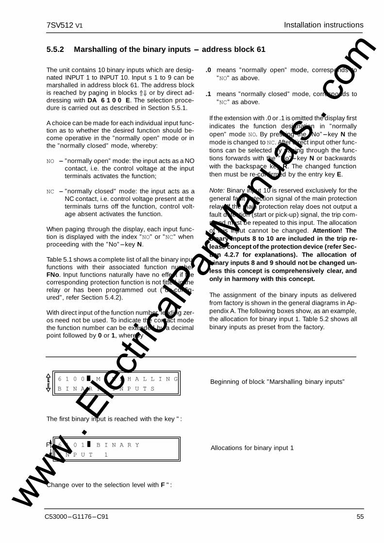
7SV512 Installation instructionsV1
55C53000---G1176---C91
5.5.2 Marshalling of the binary inputs --- address block 61
The unit contains 10 binary inputs which are desig-nated INPUT 1 to INPUT 10. Input s 1 to 9 can bemarshalled in address block 61. The address blockis reached by paging in blocks ⇑⇓ or by direct ad-dressing with DA 6 1 0 0 E. The selection proce-dure is carried out as described in Section 5.5.1.
A choice can be made for each individual input func-tion as to whether the desired function should be-come operative in the ”normally open” mode or inthe ”normally closed” mode, whereby:
NO --- ”normally open” mode: the input acts as a NOcontact, i.e. the control voltage at the inputterminals activates the function;
NC --- ”normally closed” mode: the input acts as aNC contact, i.e. control voltage present at theterminals turns off the function, control volt-age absent activates the function.
When paging through the display, each input func-tion is displayed with the index ”NO” or ”NC” whenproceeding with the ”No”---key N.
Table 5.1 shows a complete list of all the binary inputfunctions with their associated function numberFNo. Input functions naturally have no effect if thecorresponding protection function is not fitted in therelay or has been programmed out (”de-config-ured”, refer Section 5.4.2).
With direct input of the function number, leading zer-os need not be used. To indicate the contact modethe function number can be extended by a decimalpoint followed by 0 or 1, whereby
.0 means ”normally open” mode, corresponds to”NO” as above.
.1 means ”normally closed” mode, corresponds to”NC” as above.
If the extension with .0 or .1 is omitted the display firstindicates the function designation in ”normallyopen” mode NO. By pressing the ”No”---key N themode is changed to NC. After direct input other func-tions can be selected by paging through the func-tions forwards with the ”No”---key N or backwardswith the backspace key R. The changed functionthen must be re-confirmed by the entry key E.
Note: Binary input 10 is reserved exclusively for thegeneral fault detection signal of the main protectionrelay. If the main protection relay does not output afault detection (start or pick-up) signal, the trip com-mand must be repeated to this input. The allocationof this input cannot be changed. Attention! Thebinary inputs 8 to 10 are included in the trip re-lease concept of the protection device (refer Sec-tion 4.2.7 for explanations). The allocation ofbinary inputs 8 and 9 should not be changed un-less this concept is comprehensively clear, andonly in harmony with this concept.
The assignment of the binary inputs as deliveredfrom factory is shown in the general diagrams in Ap-pendix A. The following boxes show, as an example,the allocation for binary input 1. Table 5.2 shows allbinary inputs as preset from the factory.
6 1 0 0 M A R S H A L L I N G
B I N A R Y I N P U T SBeginning of block ”Marshalling binary inputs”
The first binary input is reached with the key ":
6 1 0 1 B I N A R Y
I N P U T 1Allocations for binary input 1F
Change over to the selection level with F ":www . El
ectric
alPar
tMan
uals
. com
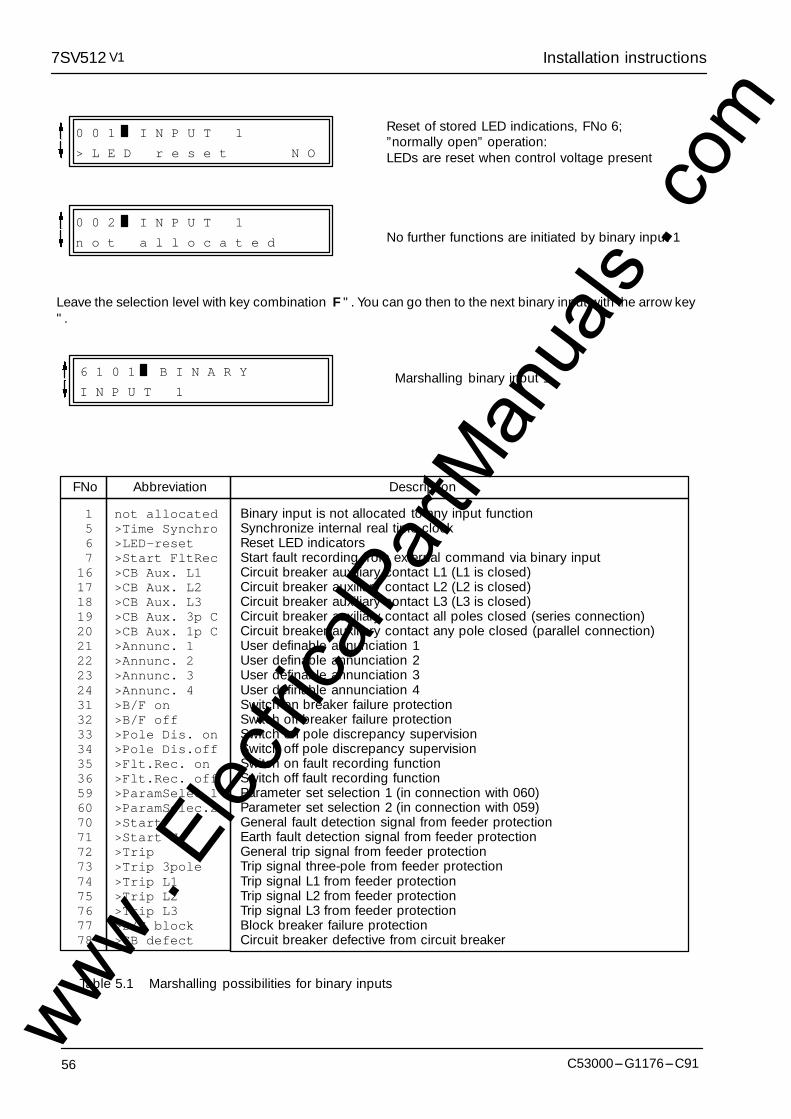
Installation instructions7SV512 V1
56 C53000---G1176---C91
0 0 2 I N P U T 1
n o t a l l o c a t e d
0 0 1 I N P U T 1
> L E D r e s e t N O
Reset of stored LED indications, FNo 6;”normally open” operation:LEDs are reset when control voltage present
No further functions are initiated by binary input 1
Leave the selection level with key combination F ". You can go then to the next binary input with the arrow key".
6 1 0 1 B I N A R Y
I N P U T 1Marshalling binary input 1
1 not allocated5 >Time Synchro6 >LED-reset7 >Start FltRec
16 >CB Aux. L117 >CB Aux. L218 >CB Aux. L319 >CB Aux. 3p C20 >CB Aux. 1p C21 >Annunc. 122 >Annunc. 223 >Annunc. 324 >Annunc. 431 >B/F on32 >B/F off33 >Pole Dis. on34 >Pole Dis.off35 >Flt.Rec. on36 >Flt.Rec. off59 >ParamSelec.160 >ParamSelec.270 >Start71 >Start N72 >Trip73 >Trip 3pole74 >Trip L175 >Trip L276 >Trip L377 >B/F block78 >CB defect
Binary input is not allocated to any input functionSynchronize internal real time clockReset LED indicatorsStart fault recording from external command via binary inputCircuit breaker auxiliary contact L1 (L1 is closed)Circuit breaker auxiliary contact L2 (L2 is closed)Circuit breaker auxiliary contact L3 (L3 is closed)Circuit breaker auxiliary contact all poles closed (series connection)Circuit breaker auxiliary contact any pole closed (parallel connection)User definable annunciation 1User definable annunciation 2User definable annunciation 3User definable annunciation 4Switch on breaker failure protectionSwitch off breaker failure protectionSwitch on pole discrepancy supervisionSwitch off pole discrepancy supervisionSwitch on fault recording functionSwitch off fault recording functionParameter set selection 1 (in connection with 060)Parameter set selection 2 (in connection with 059)General fault detection signal from feeder protectionEarth fault detection signal from feeder protectionGeneral trip signal from feeder protectionTrip signal three-pole from feeder protectionTrip signal L1 from feeder protectionTrip signal L2 from feeder protectionTrip signal L3 from feeder protectionBlock breaker failure protectionCircuit breaker defective from circuit breaker
FNo Abbreviation Description
Table 5.1 Marshalling possibilities for binary inputs
www . El
ectric
alPar
tMan
uals
. com
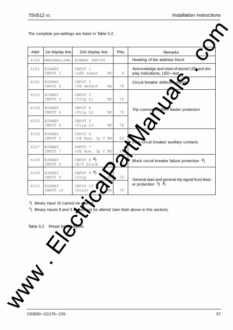
7SV512 Installation instructionsV1
57C53000---G1176---C91
The complete pre-settings are listed in Table 5.2.
6100
6101
6102
6103
6104
6105
6106
6107
6108
6109
6110
BINARY INPUTS
INPUT 1>LED reset NO
INPUT 2>CB defect NO
INPUT 3>Trip L1 NO
INPUT 4>Trip L2 NO
INPUT 5>Trip L3 NO
INPUT 6>CB Aux. 1p C NO
INPUT 7>CB Aux. 3p C NO
INPUT 8 2)>B/F block NO
INPUT 9 2)>Trip NO
INPUT 10 1)>Start NO
6
78
74
75
76
20
19
77
72
70
MARSHALLING
BINARYINPUT 1
BINARYINPUT 2
BINARYINPUT 3
BINARYINPUT 4
BINARYINPUT 5
BINARYINPUT 6
BINARYINPUT 7
BINARYINPUT 8
BINARYINPUT 9
BINARYINPUT 10
1st display lineAddr 2nd display line FNo
Heading of the address block
Acknowledge and reset of stored LED and dis-play indications, LED--- test
Circuit breaker defective signal
Trip commands from feeder protection
from circuit breaker auxiliary contacts
Block circuit breaker failure protection 2)
General start and general trip signal from feed-er protection 1) 2)
Remarks
1) Binary input 10 cannot be altered.2) Binary inputs 8 and 9 should not be altered (see Note above in this section).
Table 5.2 Preset binary inputs
www . El
ectric
alPar
tMan
uals
. com
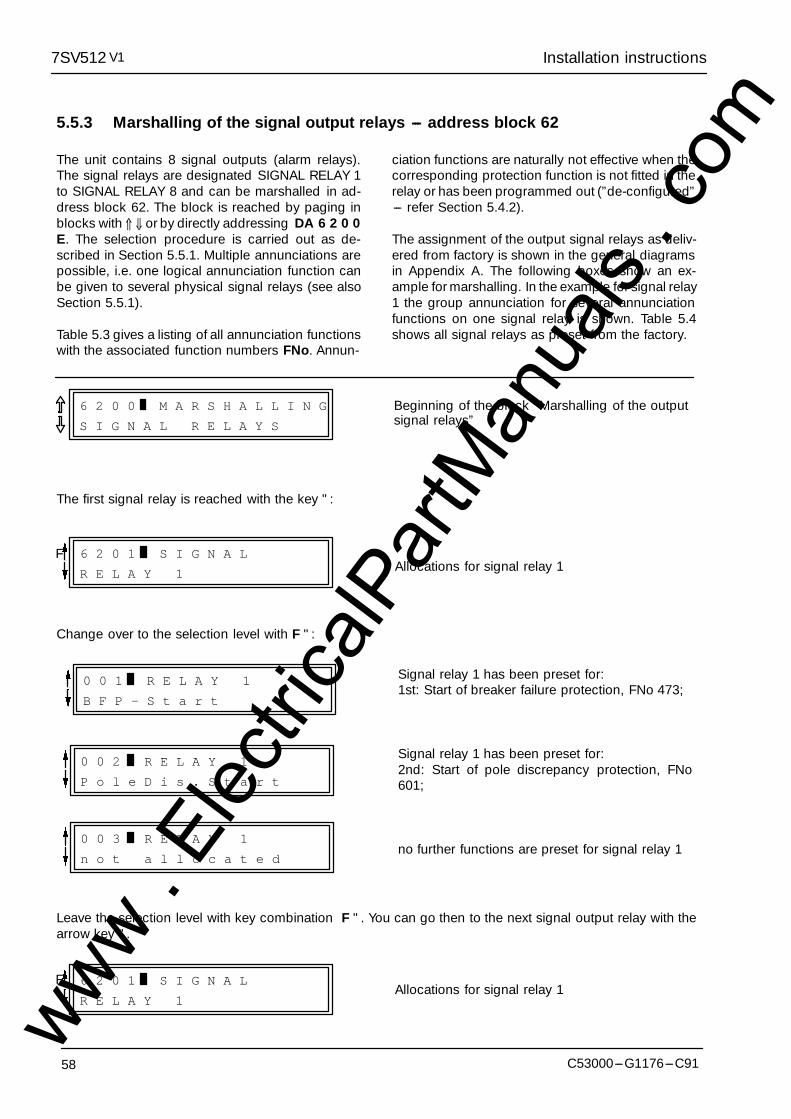
Installation instructions7SV512 V1
58 C53000---G1176---C91
5.5.3 Marshalling of the signal output relays --- address block 62
The unit contains 8 signal outputs (alarm relays).The signal relays are designated SIGNAL RELAY 1to SIGNAL RELAY 8 and can be marshalled in ad-dress block 62. The block is reached by paging inblocks with ⇑ ⇓ or by directly addressing DA 6 2 0 0E. The selection procedure is carried out as de-scribed in Section 5.5.1. Multiple annunciations arepossible, i.e. one logical annunciation function canbe given to several physical signal relays (see alsoSection 5.5.1).
Table 5.3 gives a listing of all annunciation functionswith the associated function numbers FNo. Annun-
ciation functions are naturally not effective when thecorresponding protection function is not fitted in therelay or has been programmed out (”de-configured”--- refer Section 5.4.2).
The assignment of the output signal relays as deliv-ered from factory is shown in the general diagramsin Appendix A. The following boxes show an ex-ample for marshalling. In the example for signal relay1 the group annunciation for several annunciationfunctions on one signal relay is shown. Table 5.4shows all signal relays as preset from the factory.
6 2 0 0 M A R S H A L L I N G
S I G N A L R E L A Y S
Beginning of the block ”Marshalling of the outputsignal relays”
The first signal relay is reached with the key ":
6 2 0 1 S I G N A L
R E L A Y 1 Allocations for signal relay 1F
Change over to the selection level with F ":
0 0 1 R E L A Y 1
B F P - S t a r t
0 0 2 R E L A Y 1
P o l e D i s . S t a r t
Signal relay 1 has been preset for:1st: Start of breaker failure protection, FNo 473;
Signal relay 1 has been preset for:2nd: Start of pole discrepancy protection, FNo601;
no further functions are preset for signal relay 10 0 3 R E L A Y 1
n o t a l l o c a t e d
Leave the selection level with key combination F ". You can go then to the next signal output relay with thearrow key ".
6 2 0 1 S I G N A L
R E L A Y 1Allocations for signal relay 1
F
www . El
ectric
alPar
tMan
uals
. com

7SV512 Installation instructionsV1
59C53000---G1176---C91
Note as to Table 5.3: Annunciations with the function numbers below 100 are identical with those for binaryinputs. They represent the direct confirmation of the binary input and are available as long as the correspond-ing binary input is energized. These direct confirmation functions are indicated by a leading ”>” sign.
Further information about annunciations see Section 6.4.
1 not allocated5 >Time Synchro6 >LED-reset7 >Start FltRec
16 >CB Aux. L117 >CB Aux. L218 >CB Aux. L319 >CB Aux. 3p C20 >CB Aux. 1p C21 >Annunc. 122 >Annunc. 223 >Annunc. 324 >Annunc. 431 >B/F on32 >B/F off33 >Pole Dis. on34 >Pole Dis.off35 >Flt.Rec. on36 >Flt.Rec. off59 >ParamSelec.160 >ParamSelec.270 >Start71 >Start N72 >Trip73 >Trip 3pole74 >Trip L175 >Trip L276 >Trip L377 >B/F block78 >CB defect
101 Dev.Operative107 Flt.Rec.Trans108 Fault.Rec.off110 Param.Running116 Param. Set A117 Param. Set B118 Param. Set C119 Param. Set D121 Failure 18V122 Failure 15V123 Failure 5V124 Failure 0V125 Failure RKA151 Failure �I154 Failure Isymm469 Device FltDet470 Device Trip471 BFP off472 BFP-Pickup473 BFP-Start
Binary output is not allocated to any output functionSynchronize internal real time clockReset LED indicatorsStart fault recording from external command via binary inputCircuit breaker auxiliary contact L1 (L1 is closed)Circuit breaker auxiliary contact L2 (L2 is closed)Circuit breaker auxiliary contact L3 (L3 is closed)Circuit breaker auxiliary contact all poles closed (series connection)Circuit breaker auxiliary contact any pole closed (parallel connection)User definable annunciation 1User definable annunciation 2User definable annunciation 3User definable annunciation 4Switch on breaker failure protectionSwitch off breaker failure protectionSwitch on pole discrepancy supervisionSwitch off pole discrepancy supervisionSwitch on fault recording functionSwitch off fault recording functionParameter set selection 1 (in connection with 060)Parameter set selection 2 (in connection with 059)General fault detection signal from feeder protectionEarth fault detection signal from feeder protectionGeneral trip signal from feeder protectionTrip signal three-pole from feeder protectionTrip signal L1 from feeder protectionTrip signal L2 from feeder protectionTrip signal L3 from feeder protectionBlock breaker failure protectionCircuit breaker defective (from circuit breaker monitor)Relay operativeFault record data are available or being transmittedFault recording switched offParameters are being setParameter Set A is activatedParameter Set B is activatedParameter Set C is activatedParameter Set D is activatedFailure in 18 V internal dc supplyFailure in 15 V internal dc supplyFailure in 5 V internal dc supplyFailure in 0 V A/D converterFailure in base input/output moduleFailure supervision �I (measured currents)Failure supervision symmetry IGeneral fault detection signalGeneral trip signalBreaker failure protection switched offBreaker failure protection initiated (signal from feeder protection)Breaker failure protection started
FNo Abbreviation Description
Table 5.3 Marshalling possibilities for signal relays and LEDs (Continued next page)www . El
ectric
alPar
tMan
uals
. com
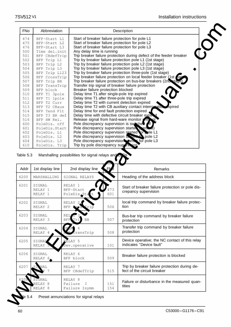
Installation instructions7SV512 V1
60 C53000---G1176---C91
474 BFP-Start L1475 BFP-Start L2476 BFP-Start L3500 Time del.init501 BFP CBdefTrip502 BFP Trip L1503 BFP Trip L2504 BFP Trip L3505 BFP Trip L123506 BFP CrossTrip507 BFP Trip BB508 BFP TransTrip509 BFP block510 BFP T1 3pole511 BFP T1 1pole512 BFP T2 Curr513 BFP T2 CBaux514 BFP Tend Flt515 BFP T3 BR def516 BFP HW Rel.600 PoleDis. off601 PoleDis.Start602 PoleDis. L1603 PoleDis. L2604 PoleDis. L3610 PoleDis. Trip
Start of breaker failure protection for pole L1Start of breaker failure protection for pole L2Start of breaker failure protection for pole L3Any delay time is runningTrip breaker failure protection during defect of the feeder breakerTrip by breaker failure protection pole L1 (1st stage)Trip by breaker failure protection pole L2 (1st stage)Trip by breaker failure protection pole L3 (1st stage)Trip by breaker failure protection three-pole (1st stage)Trip breaker failure protection on local feeder breaker (1st stage)Trip breaker failure protection on bus-bar breakers (2nd stage)Transfer trip signal of breaker failure protectionBreaker failure protection blockedDelay time T1 after single-pole trip expiredDelay time T1 after three-pole trip expiredDelay time T2 with current detection expiredDelay time T2 with CB auxiliary contact interrogation expiredDelay time for end fault protection expiredDelay time with defective circuit breaker expiredRelease signal from hard-ware monitor presentPole discrepancy supervision is switched offPole discrepancy supervision started (general)Pole discrepancy supervision started for pole L1Pole discrepancy supervision started for pole L2Pole discrepancy supervision started for pole L3Trip by pole discrepancy supervision
FNo Abbreviation Description
Table 5.3 Marshalling possibilities for signal relays and LEDs
6200
6201
6202
6203
6204
6205
6206
6207
6208
SIGNAL RELAYS
RELAY 1BFP-StartPoleDis.Start
RELAY 2BFP CrossTrip
RELAY 3BFP Trip BB
RELAY 4BFP TransTrip
RELAY 5Dev.operative
RELAY 6BFP block
RELAY 7BFP CBdefTrip
RELAY 8Failure �IFailure Isymm
473601
506
507
508
101
509
515
151154
MARSHALLING
SIGNALRELAY 1RELAY 1
SIGNALRELAY 2
SIGNALRELAY 3
SIGNALRELAY 4
SIGNALRELAY 5
SIGNALRELAY 6
SIGNALRELAY 7
SIGNALRELAY 8RELAY 8
1st display lineAddr 2nd display line FNo Remarks
Heading of the address block
Start of breaker failure protection or pole dis-crepancy supervision
local trip command by breaker failure protec-tion
Bus-bar trip command by breaker failureprotection
Transfer trip command by breaker failureprotection
Device operative; the NC contact of this relayindicates ”Device fault”
Breaker failure protection is blocked
Trip by breaker failure protection during de-fect of the circuit breaker
Failure or disturbance in the measured quan-tities
Table 5.4 Preset annunciations for signal relayswww . El
ectric
alPar
tMan
uals
. com
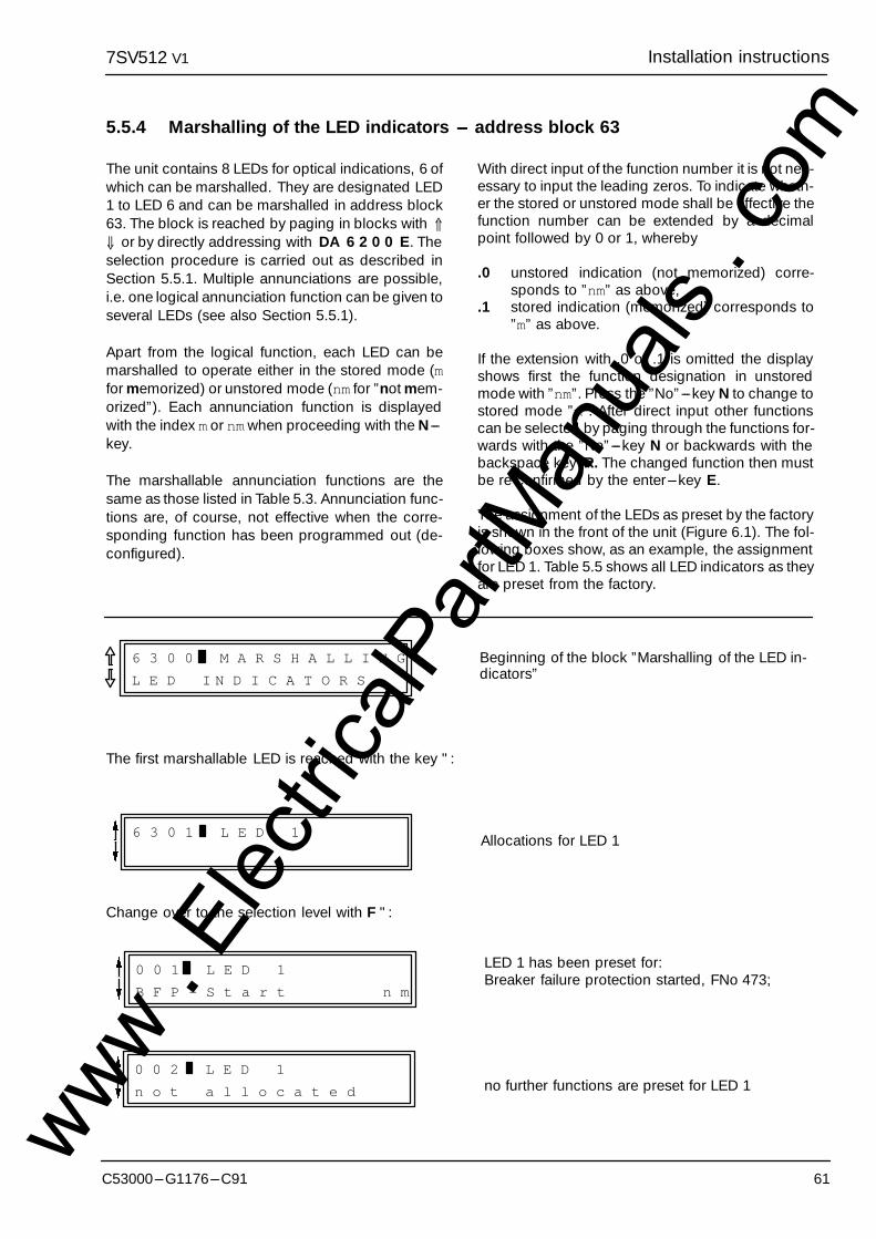
7SV512 Installation instructionsV1
61C53000---G1176---C91
5.5.4 Marshalling of the LED indicators --- address block 63
The unit contains 8 LEDs for optical indications, 6 ofwhich can be marshalled. They are designated LED1 to LED 6 and can be marshalled in address block63. The block is reached by paging in blocks with ⇑⇓ or by directly addressing with DA 6 2 0 0 E. Theselection procedure is carried out as described inSection 5.5.1. Multiple annunciations are possible,i.e. one logical annunciation function can be given toseveral LEDs (see also Section 5.5.1).
Apart from the logical function, each LED can bemarshalled to operate either in the stored mode (mfor memorized) or unstored mode (nm for ”not mem-orized”). Each annunciation function is displayedwith the index m or nmwhen proceeding with the N---key.
The marshallable annunciation functions are thesame as those listed in Table 5.3. Annunciation func-tions are, of course, not effective when the corre-sponding function has been programmed out (de-configured).
With direct input of the function number it is not nec-essary to input the leading zeros. To indicate wheth-er the stored or unstored mode shall be effective thefunction number can be extended by a decimalpoint followed by 0 or 1, whereby
.0 unstored indication (not memorized) corre-sponds to ”nm” as above,
.1 stored indication (memorized) corresponds to”m” as above.
If the extension with .0 or .1 is omitted the displayshows first the function designation in unstoredmode with ”nm”. Press the ”No”---key N to change tostored mode ”m”. After direct input other functionscan be selected by paging through the functions for-wards with the ”No”---key N or backwards with thebackspace key R. The changed function then mustbe re-confirmed by the enter---key E.
The assignment of the LEDs as preset by the factoryis shown in the front of the unit (Figure 6.1). The fol-lowing boxes show, as an example, the assignmentfor LED 1. Table 5.5 shows all LED indicators as theyare preset from the factory.
6 3 0 0 M A R S H A L L I N G
L E D I N D I C A T O R S
Beginning of the block ”Marshalling of the LED in-dicators”
The first marshallable LED is reached with the key ":
6 3 0 1 L E D 1 Allocations for LED 1
Change over to the selection level with F ":
0 0 2 L E D 1
n o t a l l o c a t e d
0 0 1 L E D 1
B F P - S t a r t n m
LED 1 has been preset for:Breaker failure protection started, FNo 473;
no further functions are preset for LED 1
www . El
ectric
alPar
tMan
uals
. com
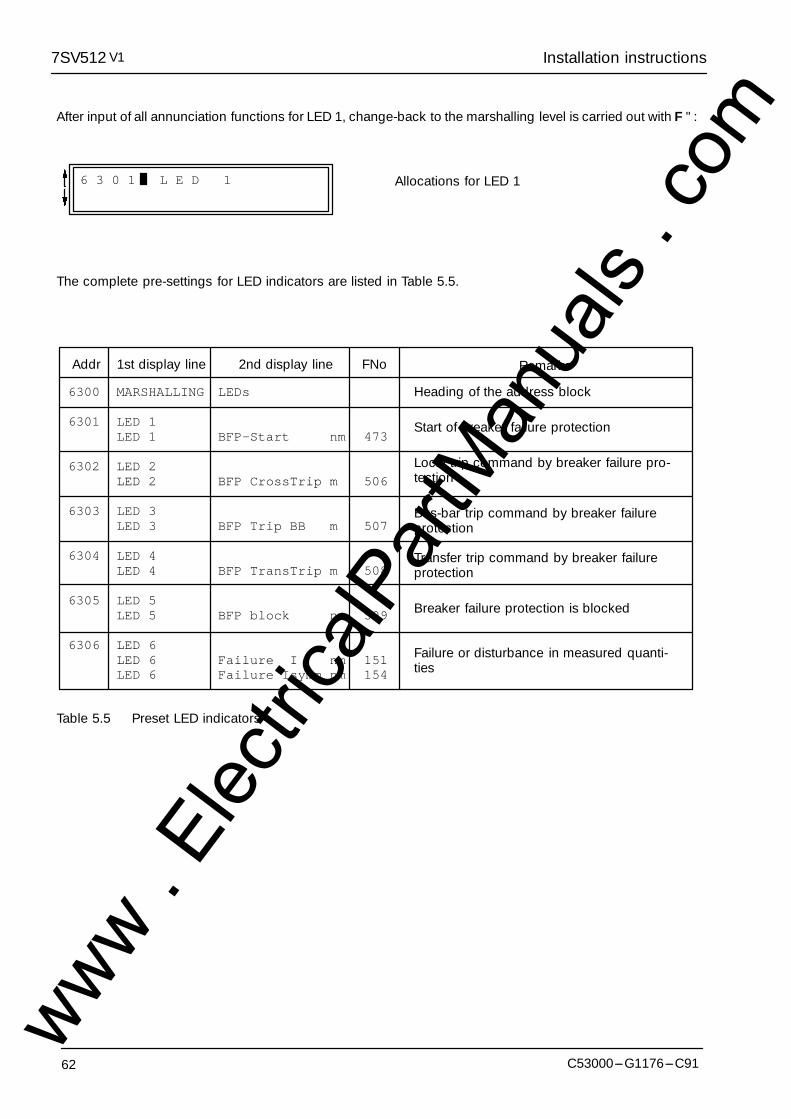
Installation instructions7SV512 V1
62 C53000---G1176---C91
After input of all annunciation functions for LED 1, change-back to the marshalling level is carried out with F ":
6 3 0 1 L E D 1 Allocations for LED 1
The complete pre-settings for LED indicators are listed in Table 5.5.
6300
6301
6302
6303
6304
6305
6306
LEDs
BFP-Start nm
BFP CrossTrip m
BFP Trip BB m
BFP TransTrip m
BFP block nm
Failure I nmFailure Isymm nm
473
506
507
508
509
151154
MARSHALLING
LED 1LED 1
LED 2LED 2
LED 3LED 3
LED 4LED 4
LED 5LED 5
LED 6LED 6LED 6
1st display lineAddr 2nd display line FNo Remarks
Heading of the address block
Start of breaker failure protection
Local trip command by breaker failure pro-tection
Bus-bar trip command by breaker failureprotection
Transfer trip command by breaker failureprotection
Breaker failure protection is blocked
Failure or disturbance in measured quanti-ties
�
Table 5.5 Preset LED indicators
www . El
ectric
alPar
tMan
uals
. com
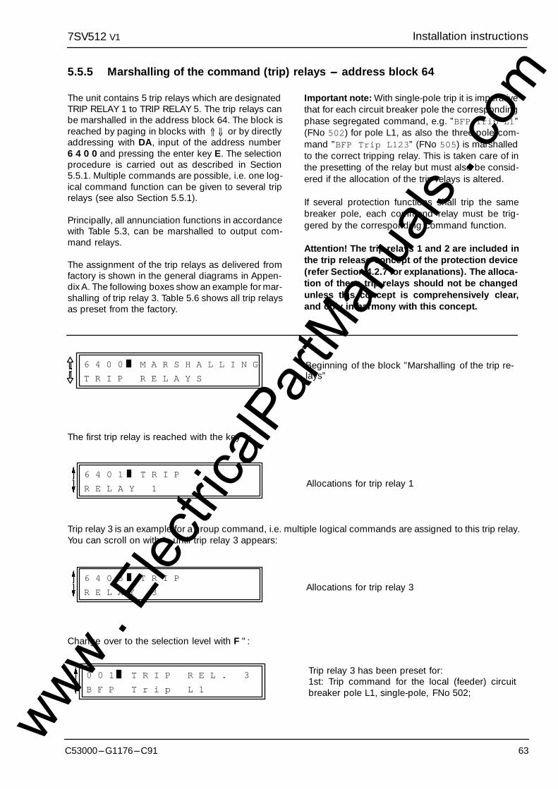
7SV512 Installation instructionsV1
63C53000---G1176---C91
5.5.5 Marshalling of the command (trip) relays --- address block 64
The unit contains 5 trip relays which are designatedTRIP RELAY 1 to TRIP RELAY 5. The trip relays canbe marshalled in the address block 64. The block isreached by paging in blocks with ⇑ ⇓ or by directlyaddressing with DA, input of the address number6 4 0 0 and pressing the enter key E. The selectionprocedure is carried out as described in Section5.5.1. Multiple commands are possible, i.e. one log-ical command function can be given to several triprelays (see also Section 5.5.1).
Principally, all annunciation functions in accordancewith Table 5.3, can be marshalled to output com-mand relays.
The assignment of the trip relays as delivered fromfactory is shown in the general diagrams in Appen-dix A. The following boxes show an example for mar-shalling of trip relay 3. Table 5.6 shows all trip relaysas preset from the factory.
Important note: With single-pole trip it is imperativethat for each circuit breaker pole the correspondingphase segregated command, e.g. ”BFP Trip L1”(FNo 502) for pole L1, as also the three-pole com-mand ”BFP Trip L123” (FNo 505) is marshalledto the correct tripping relay. This is taken care of inthe presetting of the relay but must also be consid-ered if the allocation of the trip relays is altered.
If several protection functions shall trip the samebreaker pole, each command relay must be trig-gered by the corresponding command function.
Attention! The trip relays 1 and 2 are included inthe trip release concept of the protection device(refer Section 4.2.7 for explanations). The alloca-tion of these trip relays should not be changedunless this concept is comprehensively clear,and only in harmony with this concept.
6 4 0 0 M A R S H A L L I N G
T R I P R E L A Y S
Beginning of the block ”Marshalling of the trip re-lays”
The first trip relay is reached with the key ":
6 4 0 1 T R I P
R E L A Y 1 Allocations for trip relay 1
Trip relay 3 is an example for a group command, i.e. multiple logical commands are assigned to this trip relay.You can scroll on with ", until trip relay 3 appears:
6 4 0 3 T R I P
R E L A Y 3 Allocations for trip relay 3
Change over to the selection level with F ":
0 0 1 T R I P R E L . 3
B F P T r i p L 1
Trip relay 3 has been preset for:1st: Trip command for the local (feeder) circuitbreaker pole L1, single-pole, FNo 502;
www . El
ectric
alPar
tMan
uals
. com
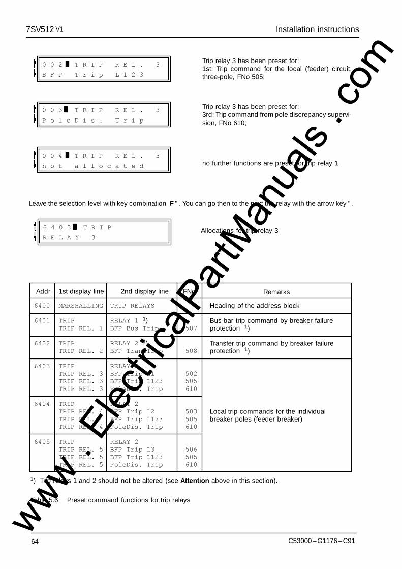
Installation instructions7SV512 V1
64 C53000---G1176---C91
0 0 2 T R I P R E L . 3
B F P T r i p L 1 2 3
Trip relay 3 has been preset for:1st: Trip command for the local (feeder) circuit,three-pole, FNo 505;
0 0 4 T R I P R E L . 3
n o t a l l o c a t e d
0 0 3 T R I P R E L . 3
P o l e D i s . T r i p
Trip relay 3 has been preset for:3rd: Trip command from pole discrepancy supervi-sion, FNo 610;
no further functions are preset for trip relay 1
Leave the selection level with key combination F ". You can go then to the next trip relay with the arrow key ".
6 4 0 3 T R I P
R E L A Y 3Allocations for trip relay 3
6400
6401
6402
6403
6404
6405
TRIP RELAYS
RELAY 1 1)BFP Bus Trip
RELAY 2 1)BFP TransTrip
RELAY 2BFP Trip L1BFP Trip L123PoleDis. Trip
RELAY 2BFP Trip L2BFP Trip L123PoleDis. Trip
RELAY 2BFP Trip L3BFP Trip L123PoleDis. Trip
507
508
502505610
503505610
506505610
MARSHALLING
TRIPTRIP REL. 1
TRIPTRIP REL. 2
TRIPTRIP REL. 3TRIP REL. 3TRIP REL. 3
TRIPTRIP REL. 4TRIP REL. 4TRIP REL. 4
TRIPTRIP REL. 5TRIP REL. 5TRIP REL. 5
1st display lineAddr 2nd display line FNo Remarks
Heading of the address block
Bus-bar trip command by breaker failureprotection 1)
Transfer trip command by breaker failureprotection 1)
Local trip commands for the individualbreaker poles (feeder breaker)
1) Trip relays 1 and 2 should not be altered (see Attention above in this section).
Table 5.6 Preset command functions for trip relays
www . El
ectric
alPar
tMan
uals
. com
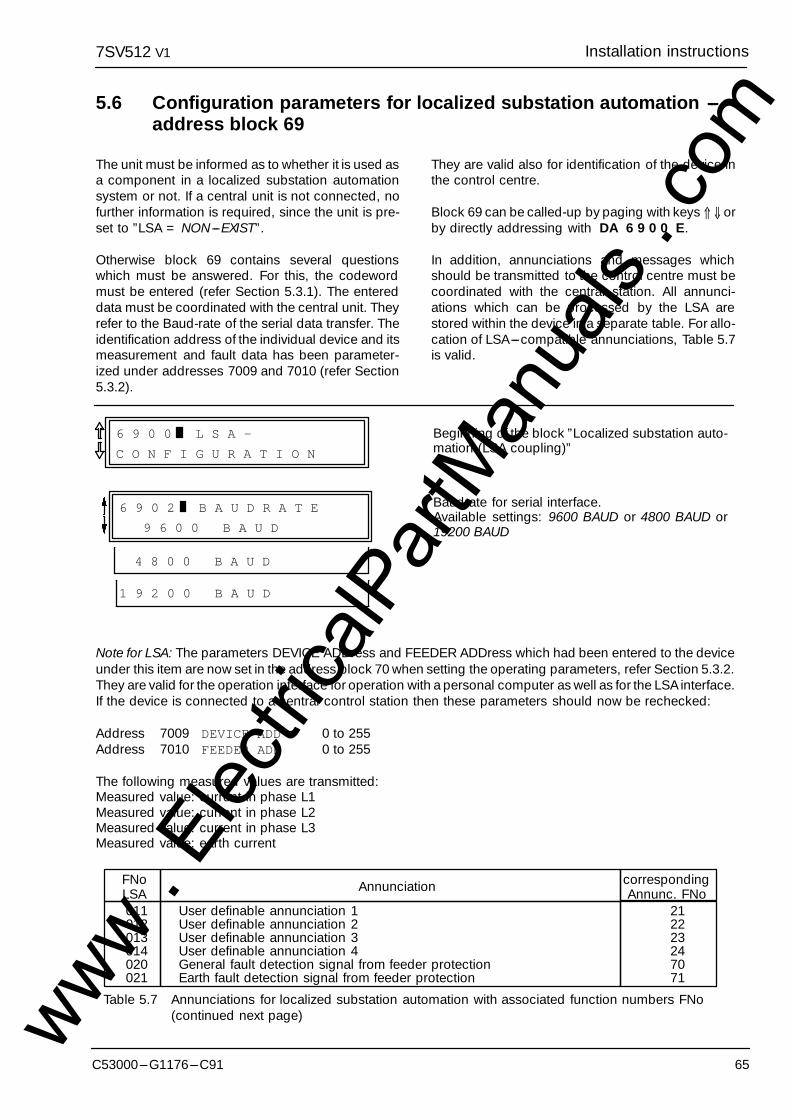
7SV512 Installation instructionsV1
65C53000---G1176---C91
5.6 Configuration parameters for localized substation automation ---address block 69
The unit must be informed as to whether it is used asa component in a localized substation automationsystem or not. If a central unit is not connected, nofurther information is required, since the unit is pre-set to ”LSA = NON---EXIST”.
Otherwise block 69 contains several questionswhich must be answered. For this, the codewordmust be entered (refer Section 5.3.1). The entereddata must be coordinated with the central unit. Theyrefer to the Baud-rate of the serial data transfer. Theidentification address of the individual device and itsmeasurement and fault data has been parameter-ized under addresses 7009 and 7010 (refer Section5.3.2).
They are valid also for identification of the device inthe control centre.
Block 69 can be called-up by paging with keys ⇑ ⇓ orby directly addressing with DA 6 9 0 0 E.
In addition, annunciations and messages whichshould be transmitted to the control centre must becoordinated with the central station. All annunci-ations which can be processed by the LSA arestored within the device in a separate table. For allo-cation of LSA---compatible annunciations, Table 5.7is valid.
6 9 0 0 L S A -
C O N F I G U R A T I O N
Beginning of the block ”Localized substation auto-mation (LSA coupling)”
Baudrate for serial interface.Available settings: 9600 BAUD or 4800 BAUD or19200 BAUD
4 8 0 0 B A U D
6 9 0 2 B A U D R A T E
9 6 0 0 B A U D
1 9 2 0 0 B A U D
Note for LSA: The parameters DEVICE ADDress and FEEDER ADDress which had been entered to the deviceunder this item are now set in the address block 70 when setting the operating parameters, refer Section 5.3.2.They are valid for the operation interface for operation with a personal computer as well as for the LSA interface.If the device is connected to a central control station then these parameters should now be rechecked:
Address 7009 DEVICE ADD 0 to 255Address 7010 FEEDER ADD 0 to 255
The following measured values are transmitted:Measured value: current in phase L1Measured value: current in phase L2Measured value: current in phase L3Measured value: earth current
correspondingAnnunc. FNo
011012013014020021
User definable annunciation 1User definable annunciation 2User definable annunciation 3User definable annunciation 4General fault detection signal from feeder protectionEarth fault detection signal from feeder protection
FNoLSA Annunciation
212223247071
Table 5.7 Annunciations for localized substation automation with associated function numbers FNo(continued next page)www .
Elec
tricalP
artM
anua
ls . c
om
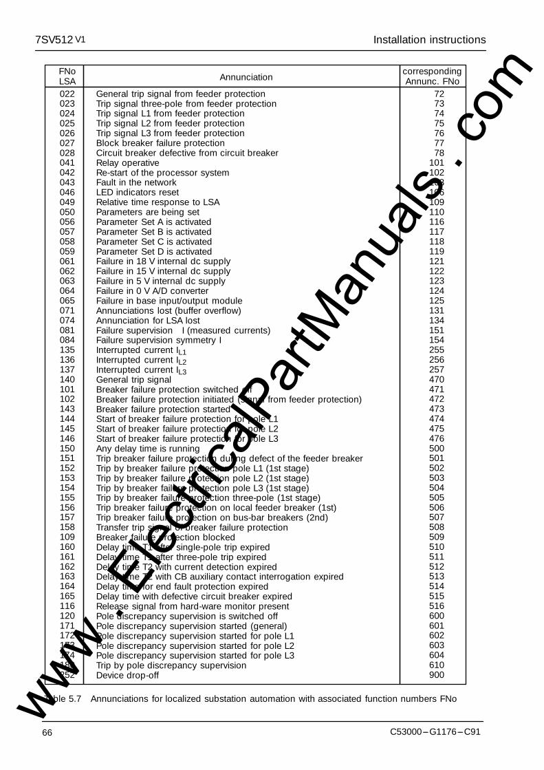
Installation instructions7SV512 V1
66 C53000---G1176---C91
022023024025026027028041042043046049050056057058059061062063064065071074081084135136137140101102143144145146150151152153154155156157158109160161162163164165116120171172173174180252
General trip signal from feeder protectionTrip signal three-pole from feeder protectionTrip signal L1 from feeder protectionTrip signal L2 from feeder protectionTrip signal L3 from feeder protectionBlock breaker failure protectionCircuit breaker defective from circuit breakerRelay operativeRe-start of the processor systemFault in the networkLED indicators resetRelative time response to LSAParameters are being setParameter Set A is activatedParameter Set B is activatedParameter Set C is activatedParameter Set D is activatedFailure in 18 V internal dc supplyFailure in 15 V internal dc supplyFailure in 5 V internal dc supplyFailure in 0 V A/D converterFailure in base input/output moduleAnnunciations lost (buffer overflow)Annunciation for LSA lostFailure supervision �I (measured currents)Failure supervision symmetry IInterrupted current IL1Interrupted current IL2Interrupted current IL3General trip signalBreaker failure protection switched offBreaker failure protection initiated (signal from feeder protection)Breaker failure protection startedStart of breaker failure protection for pole L1Start of breaker failure protection for pole L2Start of breaker failure protection for pole L3Any delay time is runningTrip breaker failure protection during defect of the feeder breakerTrip by breaker failure protection pole L1 (1st stage)Trip by breaker failure protection pole L2 (1st stage)Trip by breaker failure protection pole L3 (1st stage)Trip by breaker failure protection three-pole (1st stage)Trip breaker failure protection on local feeder breaker (1st)Trip breaker failure protection on bus-bar breakers (2nd)Transfer trip signal of breaker failure protectionBreaker failure protection blockedDelay time T1 after single-pole trip expiredDelay time T1 after three-pole trip expiredDelay time T2 with current detection expiredDelay time T2 with CB auxiliary contact interrogation expiredDelay time for end fault protection expiredDelay time with defective circuit breaker expiredRelease signal from hard-ware monitor presentPole discrepancy supervision is switched offPole discrepancy supervision started (general)Pole discrepancy supervision started for pole L1Pole discrepancy supervision started for pole L2Pole discrepancy supervision started for pole L3Trip by pole discrepancy supervisionDevice drop-off
FNoLSA
correspondingAnnunc. FNoAnnunciation
72737475767778
101102103106109110116117118119121122123124125131134151154255256257470471472473474475476500501502503504505506507508509510511512513514515516600601602603604610900
Table 5.7 Annunciations for localized substation automation with associated function numbers FNowww . El
ectric
alPar
tMan
uals
. com

Operating instructions7SV512 V1
67C53000---G1176---C91
6 Operating instructions
6.1 Safety precautions
All safety precautions which apply for workin electrical installations are to be observedduring tests and commissioning.
! Warning
Connection of the device to a battery char-ger without connected battery may causeimpermissibly high voltages which damagethe device. See also Section 3.1.1 underTechnical data for limits.
! Caution!
6.2 Dialog with the relay
Setting, operation and interrogation of digital protec-tion and automation systems can be carried out viathe integrated membrane keyboard and displaypanel located on the front plate. All the necessaryoperating parameters can be entered and all the in-formation can be read out from here. Operation is,additionally, possible via the interface socket bymeans of a personal computer or similar.
6.2.1 Membrane keyboard and dis-play panel
The membrane keyboard and display panel is exter-nally arranged similar to a pocket calculator. Figure6.1 illustrates the front view.
A two-line, each 16 character, liquid crystal displaypresents the information. Each character comprisesa 5 x 8 dot matrix. Numbers, letters and a series ofspecial symbols can be displayed.
During dialog, the upper line gives a four figure num-ber, followed by a bar. This number presents the set-ting address. The first two digits indicate the ad-dress block, then follows the two-digit sequencenumber. In models with parameter change-over fa-cility, the identifier of the parameter set is shown be-fore the setting address.
The keyboard comprises 28 keys with numbers,Yes/No and control buttons. The significance of thekeys is explained in detail in the following.
Numerical keys for the input of numerals:
+/---
to Digits 0 to 9 for numerical input
Decimal point
Infinity symbol1
Change of sign (input ofnegative numbers)
90
J/Y
N
Yes key: operator affirms the dis-played question
Yes/No keys for text parameters:
No key: operator denies the dis-played question or rejects a sug-gestion and requests for alterna-tive
Keys for paging through the display:
Paging forwards: the next ad-dress is displayed
Paging backwards: the previousaddress is displayed
Block paging forwards: the be-ginning of the next address blockis displayed
Block paging backwards: the be-ginning of previous addressblock is displayedwww .
Elec
tricalP
artM
anua
ls . c
om

Operating instructions7SV512 V1
C53000---G1176---C9168
E
Confirmation key:
Enter or confirmation key: eachnumerical input or change via theYes/No keys must be confirmed bythe enter key; only then does thedevice accept the change. The en-ter key can also be used to ac-knowledge and clear a faultprompt in this display; a new inputand repeated use of the enter keyis then necessary.
CW
R
F
DA
M/S
Control and special keys:
Codeword: prevents unautho-rized access to setting programs(not necessary for call-up of an-nunciations or messages)
Backspace erasure of incorrectentries
Function key; explained whenused
Direct addressing: if the addressnumber is known, this key allowsdirect call-up of the address
Messages/Signals: interrogationof annunciations of fault and oper-ating data (refer Section 6.4)
The three keys " ; ⇑ ; RESET which are somewhatseparated from the rest of the keys, can be ac-cessed when the front cover is closed. The arrowshave the same function as the keys with identicalsymbols in the main field and enable paging in for-ward direction. Thus all setting values and eventdata can be displayed with the front cover closed.Furthermore, stored LED indications on the front canbe erased via the RESET key without opening thefront cover. During reset operation all LEDs on thefront will be illuminated thus performing a LED test.With this reset, additionally, the fault event indica-tions in the display on the front panel of the deviceare acknowledged; the display shows then the op-erational values of the quiescent state. The display isswitched over to operating mode as soon as one ofthe keys DA, M/S, CW or ⇑ is pressed.
6.2.2 Operation with a personal com-puter
A personal computer allows, just as the operatorpanel, all the appropriate settings, initiation of testroutines and read-out of data, but with the addedcomfort of screen-based visualization and a menu-guided procedure.
All data can be read in from, or copied onto, magnet-ic data carrier (floppy disc) (e.g. for settings and con-figuration). Additionally, all the data can be docu-mented on a connected printer. It is also possible, byconnecting a plotter, to print out the fault historytraces.
For operation of the personal computer, the instruc-tion manuals of this device are to be observed. ThePC program DIGSI�is available for setting and pro-cessing of all digital protection data. Note that theoperating interface in the front of the relay is not gal-vanically isolated and that only adequate connec-tion cables are applied (e.g. 7XV5100---2). Furtherinformation about facilities on request.
6.2.3 Operational preconditions
For most operational functions, the input of a code-word is necessary. This applies for all entries via themembrane keyboard or front interface which con-cern the operation on the relay, for example
--- setting of functional parameters (thresholds,functions),
--- allocation or marshalling of trip relays, signals,binary inputs, LED indicators,
--- configuration parameters for operation languageand device configuration,
--- initiation of test procedures.
The codeword is not required for the read-out of an-nunciations, operating data or fault data, or for theread-out of setting parameters.
The method of entry of the codeword is explained indetail in the installation instructions under Section5.3.1.
www . El
ectric
alPar
tMan
uals
. com

Operating instructions7SV512 V1
69C53000---G1176---C91
6.2.4 Representation of the relay (front view)
[∇III]
987CW
654R
321F
0DA
E+/---NJ/YM/S
F---Nr.7SV512
Diagr.:
I =1AN
U = 60,110,125V---H
2
SchalterversagerschutzBreaker Fail Protection
Betrieb/Service
Störung/Blocked
1
2
3
4
5
6
RESETLED
C73207---A306---X1---*---12
n
Two line display(LCD) with 16 charac-ters each
Additional keys,can be accessedwhen cover isclosed
Unit faulty indication(red)
Readiness indication(green)
Operatorpanel
25pole socket for con-necting a personalcomputer
LED 1 to 6 (red) canbe marshalled; pre-setting shown below*)
On/OFF switch
*) Factory presetting LEDs:
1 B/F protection start2 B/F trip local breaker3 B/F trip bus-bar breakers4 B/F trip remote breaker (transmission)5 B/F blocked6 Measured values faulty
fN = 50 ...60 Hz[∇III]
Figure 6.1 Front view of operating key board and display panelwww . El
ectric
alPar
tMan
uals
. com
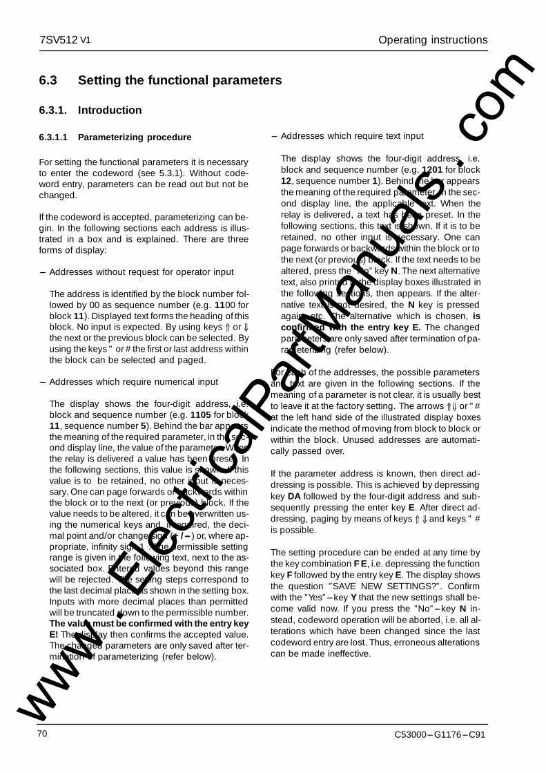
Operating instructions7SV512 V1
C53000---G1176---C9170
6.3 Setting the functional parameters
6.3.1. Introduction
6.3.1.1 Parameterizing procedure
For setting the functional parameters it is necessaryto enter the codeword (see 5.3.1). Without code-word entry, parameters can be read out but not bechanged.
If the codeword is accepted, parameterizing can be-gin. In the following sections each address is illus-trated in a box and is explained. There are threeforms of display:
--- Addresses without request for operator input
The address is identified by the block number fol-lowed by 00 as sequence number (e.g. 1100 forblock 11). Displayed text forms the heading of thisblock. No input is expected. By using keys ⇑ or ⇓the next or the previous block can be selected. Byusing the keys " or # the first or last address withinthe block can be selected and paged.
--- Addresses which require numerical input
The display shows the four-digit address, i.e.block and sequence number (e.g. 1105 for block11, sequence number 5). Behind the bar appearsthe meaning of the required parameter, in the sec-ond display line, the value of the parameter. Whenthe relay is delivered a value has been preset. Inthe following sections, this value is shown. If thisvalue is to be retained, no other input is neces-sary. One can page forwards or backwards withinthe block or to the next (or previous) block. If thevalue needs to be altered, it can be overwritten us-ing the numerical keys and, if required, the deci-mal point and/or change sign (+/--- ) or, where ap-propriate, infinity sign 1. The permissible settingrange is given in the following text, next to the as-sociated box. Entered values beyond this rangewill be rejected. The setting steps correspond tothe last decimal place as shown in the setting box.Inputs with more decimal places than permittedwill be truncated down to the permissible number.The value must be confirmed with the entry keyE! The display then confirms the accepted value.The changed parameters are only saved after ter-mination of parameterizing (refer below).
--- Addresses which require text input
The display shows the four-digit address, i.e.block and sequence number (e.g. 1201 for block12, sequence number 1). Behind the bar appearsthe meaning of the required parameter, in the sec-ond display line, the applicable text. When therelay is delivered, a text has been preset. In thefollowing sections, this text is shown. If it is to beretained, no other input is necessary. One canpage forwards or backwards within the block or tothe next (or previous) block. If the text needs to bealtered, press the ”No” key N. The next alternativetext, also printed in the display boxes illustrated inthe following sections, then appears. If the alter-native text is not desired, the N key is pressedagain, etc. The alternative which is chosen, isconfirmed with the entry key E. The changedparameters are only saved after termination of pa-rameterizing (refer below).
For each of the addresses, the possible parametersand text are given in the following sections. If themeaning of a parameter is not clear, it is usually bestto leave it at the factory setting. The arrows ⇑⇓ or "#at the left hand side of the illustrated display boxesindicate the method of moving from block to block orwithin the block. Unused addresses are automati-cally passed over.
If the parameter address is known, then direct ad-dressing is possible. This is achieved by depressingkey DA followed by the four-digit address and sub-sequently pressing the enter key E. After direct ad-dressing, paging by means of keys ⇑ ⇓ and keys " #is possible.
The setting procedure can be ended at any time bythe key combination F E, i.e. depressing the functionkey F followed by the entry key E. The display showsthe question ”SAVE NEW SETTINGS?”. Confirmwith the ”Yes”---key Y that the new settings shall be-come valid now. If you press the ”No”---key N in-stead, codeword operation will be aborted, i.e. all al-terations which have been changed since the lastcodeword entry are lost. Thus, erroneous alterationscan be made ineffective.
www . El
ectric
alPar
tMan
uals
. com
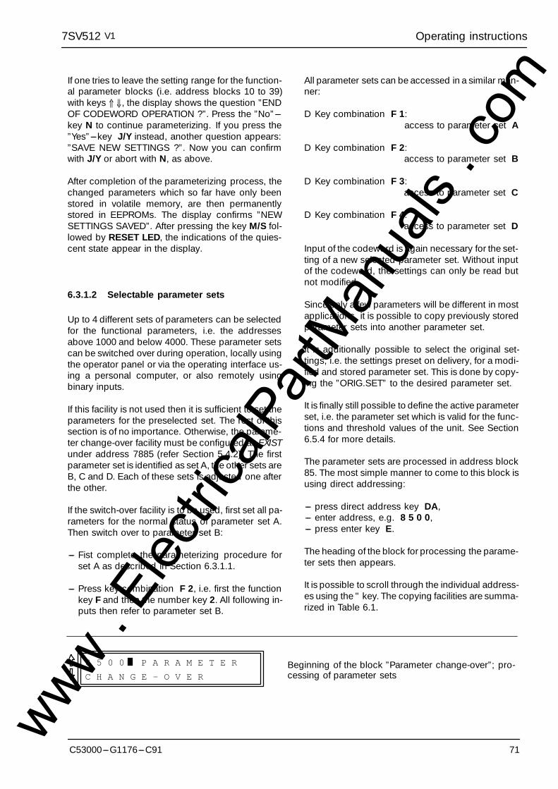
Operating instructions7SV512 V1
71C53000---G1176---C91
If one tries to leave the setting range for the function-al parameter blocks (i.e. address blocks 10 to 39)with keys ⇑ ⇓, the display shows the question ”ENDOF CODEWORD OPERATION ?”. Press the ”No”---key N to continue parameterizing. If you press the”Yes”---key J/Y instead, another question appears:”SAVE NEW SETTINGS ?”. Now you can confirmwith J/Y or abort with N, as above.
After completion of the parameterizing process, thechanged parameters which so far have only beenstored in volatile memory, are then permanentlystored in EEPROMs. The display confirms ”NEWSETTINGS SAVED”. After pressing the key M/S fol-lowed by RESET LED, the indications of the quies-cent state appear in the display.
6.3.1.2 Selectable parameter sets
Up to 4 different sets of parameters can be selectedfor the functional parameters, i.e. the addressesabove 1000 and below 4000. These parameter setscan be switched over during operation, locally usingthe operator panel or via the operating interface us-ing a personal computer, or also remotely usingbinary inputs.
If this facility is not used then it is sufficient to set theparameters for the preselected set. The rest of thissection is of no importance. Otherwise, the parame-ter change-over facility must be configured as EXISTunder address 7885 (refer Section 5.4.2). The firstparameter set is identified as set A, the other sets areB, C and D. Each of these sets is adjusted one afterthe other.
If the switch-over facility is to be used, first set all pa-rameters for the normal status of parameter set A.Then switch over to parameter set B:
--- Fist complete the parameterizing procedure forset A as described in Section 6.3.1.1.
--- Press key combination F 2, i.e. first the functionkey F and then the number key 2. All following in-puts then refer to parameter set B.
All parameter sets can be accessed in a similar man-ner:
D Key combination F 1:access to parameter set A
D Key combination F 2:access to parameter set B
D Key combination F 3:access to parameter set C
D Key combination F 4:access to parameter set D
Input of the codeword is again necessary for the set-ting of a new selected parameter set. Without inputof the codeword, the settings can only be read butnot modified.
Since only a few parameters will be different in mostapplications, it is possible to copy previously storedparameter sets into another parameter set.
It is additionally possible to select the original set-tings, i.e. the settings preset on delivery, for a modi-fied and stored parameter set. This is done by copy-ing the ”ORIG.SET” to the desired parameter set.
It is finally still possible to define the active parameterset, i.e. the parameter set which is valid for the func-tions and threshold values of the unit. See Section6.5.4 for more details.
The parameter sets are processed in address block85. The most simple manner to come to this block isusing direct addressing:
--- press direct address key DA,--- enter address, e.g. 8 5 0 0,--- press enter key E.
The heading of the block for processing the parame-ter sets then appears.
It is possible to scroll through the individual address-es using the " key. The copying facilities are summa-rized in Table 6.1.
8 5 0 0 P A R A M E T E R
C H A N G E - O V E RBeginning of the block ”Parameter change-over”; pro-cessing of parameter sets
www . El
ectric
alPar
tMan
uals
. com
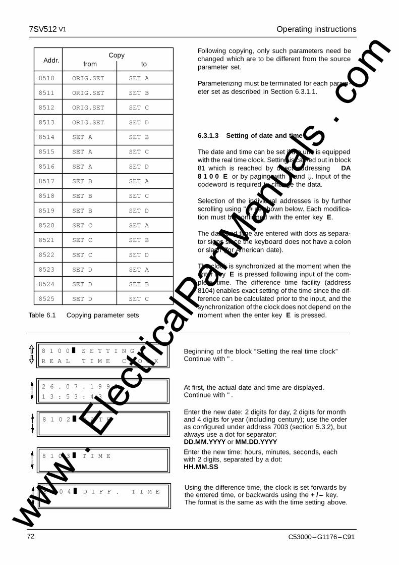
Operating instructions7SV512 V1
C53000---G1176---C9172
8510
8511
8512
8513
8514
8515
8516
8517
8518
8519
8520
8521
8522
8523
8524
8525
SET A
SET B
SET C
SET D
SET B
SET C
SET D
SET A
SET C
SET D
SET A
SET B
SET D
SET A
SET B
SET C
ORIG.SET
ORIG.SET
ORIG.SET
ORIG.SET
SET A
SET A
SET A
SET B
SET B
SET B
SET C
SET C
SET C
SET D
SET D
SET D
fromAddr. toCopy
Table 6.1 Copying parameter sets
Following copying, only such parameters need bechanged which are to be different from the sourceparameter set.
Parameterizing must be terminated for each param-eter set as described in Section 6.3.1.1.
6.3.1.3 Setting of date and time
The date and time can be set if the unit is equippedwith the real time clock. Setting is carried out in block81 which is reached by direct addressing DA8 1 0 0 E or by paging with ⇑ and ⇓. Input of thecodeword is required to change the data.
Selection of the individual addresses is by furtherscrolling using " # as shown below. Each modifica-tion must be confirmed with the enter key E.
The date and time are entered with dots as separa-tor signs since the keyboard does not have a colonor slash (for American date).
The clock is synchronized at the moment when theenter key E is pressed following input of the com-plete time. The difference time facility (address8104) enables exact setting of the time since the dif-ference can be calculated prior to the input, and thesynchronization of the clock does not depend on themoment when the enter key E is pressed.
2 6 . 0 7 . 1 9 9 3
1 3 : 5 3 : 4 3
8 1 0 0 S E T T I N G
R E A L T I M E C L O C K
Beginning of the block ”Setting the real time clock”Continue with ".
At first, the actual date and time are displayed.Continue with ".
8 1 0 2 D A T EEnter the new date: 2 digits for day, 2 digits for monthand 4 digits for year (including century); use the orderas configured under address 7003 (section 5.3.2), butalways use a dot for separator:DD.MM.YYYY or MM.DD.YYYY
8 1 0 3 T I M EEnter the new time: hours, minutes, seconds, eachwith 2 digits, separated by a dot:HH.MM.SS
8 1 0 4 D I F F . T I M EUsing the difference time, the clock is set forwards bythe entered time, or backwards using the +/--- key.The format is the same as with the time setting above.
www . El
ectric
alPar
tMan
uals
. com
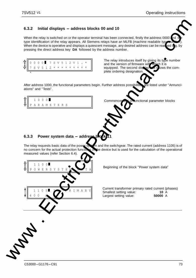
Operating instructions7SV512 V1
73C53000---G1176---C91
6.3.2 Initial displays --- address blocks 00 and 10
When the relay is switched on or the operator terminal has been connected, firstly the address 0000 and thetype identification of the relay appears. All Siemens relays have an MLFB (machine readable type number).When the device is operative and displays a quiescent message, any desired address can be reached e.g. bypressing the direct address key DA followed by the address number.
0 0 0 0 7 S V 5 1 2 V 1 . *
7 S V 5 1 2 * * * * * * * * *
*
The relay introduces itself by giving its type numberand the version of firmware with which it isequipped. The second display line shows the com-plete ordering designation.
After address 1000, the functional parameters begin. Further address possibilities are listed under ”Annunci-ations” and ”Tests”.
1 0 0 0
P A R A M E T E R SCommencement of functional parameter blocks
6.3.3 Power system data --- address block 11
The relay requests basic data of the power system and the switchgear. The rated current (address 1105) is ofno concern for the actual protection functions of the device but is used for the calculation of the operationalmeasured values (refer Section 6.4).
1 1 0 0
P O W E R S Y S T E M D A T ABeginning of the block ”Power system data”
1 1 0 5 I n P R I M A R Y
4 0 0 A
Current transformer primary rated current (phases)Smallest setting value: 10 ALargest setting value: 50000 A
www . El
ectric
alPar
tMan
uals
. com
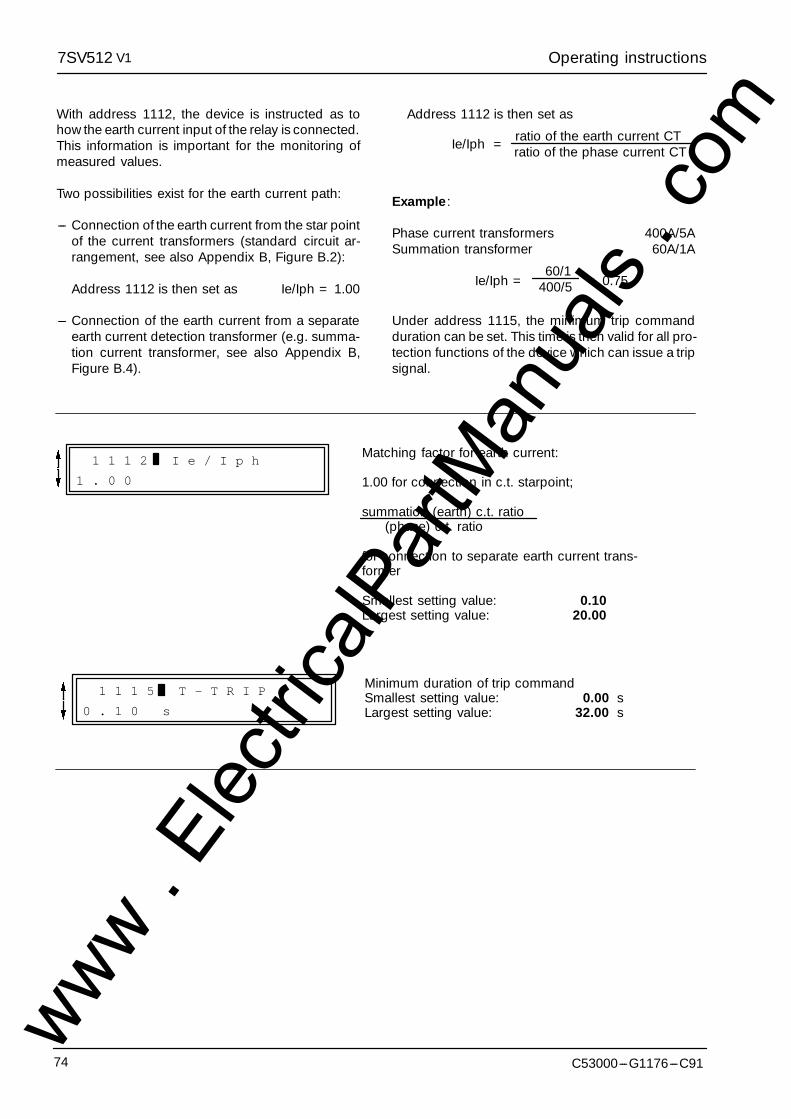
Operating instructions7SV512 V1
C53000---G1176---C9174
With address 1112, the device is instructed as tohow the earth current input of the relay is connected.This information is important for the monitoring ofmeasured values.
Two possibilities exist for the earth current path:
--- Connection of the earth current from the star pointof the current transformers (standard circuit ar-rangement, see also Appendix B, Figure B.2):
Address 1112 is then set as Ie/Iph = 1.00
--- Connection of the earth current from a separateearth current detection transformer (e.g. summa-tion current transformer, see also Appendix B,Figure B.4).
Address 1112 is then set as
ratio of the earth current CTratio of the phase current CTIe/Iph =
Example:
Phase current transformers 400A/5ASummation transformer 60A/1A
60/1400/5 = 0.75Ie/Iph =
Under address 1115, the minimum trip commandduration can be set. This time is then valid for all pro-tection functions of the device which can issue a tripsignal.
1 1 1 2 I e / I p h
1 . 0 0
Matching factor for earth current:
1.00 for connection in c.t. starpoint;
summation (earth) c.t. ratio(phase) c.t. ratio
for connection to separate earth current trans-former
Smallest setting value: 0.10Largest setting value: 20.00
1 1 1 5 T - T R I P
0 . 1 0 s
Minimum duration of trip commandSmallest setting value: 0.00 sLargest setting value: 32.00 s
www . El
ectric
alPar
tMan
uals
. com
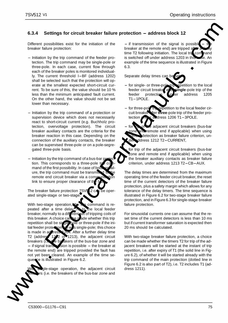
Operating instructions7SV512 V1
75C53000---G1176---C91
6.3.4 Settings for circuit breaker failure protection --- address block 12
Different possibilities exist for the initiation of thebreaker failure protection:
--- Initiation by the trip command of the feeder pro-tection. The trip command may be single-pole orthree-pole. In each case, current flow througheach of the breaker poles is monitored individual-ly. The current threshold I---BF (address 1202)shall be selected such that the protection will op-erate at the smallest expected short-circuit cur-rent. To be sure of this, the value should be 10 %less than the minimum anticipated fault current.On the other hand, the value should not be setlower than necessary.
--- Initiation by the trip command of a protection orsupervision device which does not necessarilyreact to short-circuit current (e.g. Buchholz pro-tection, overvoltage protection). The circuitbreaker auxiliary contacts are the criteria for thebreaker reaction in this case. Depending on theconnection of the auxiliary contacts, the breakercan be supervised three-pole or on a pole-segre-gated three-pole basis.
--- Initiation by the trip command of a bus-bar protec-tion. This corresponds to a three-pole trip com-mand of the first possibility. In case of breaker fail-ure, the trip command must be transmitted to theremote end circuit breaker via a communicationlink to ensure proper clearance of the fault.
The breaker failure protection 7SV512 can be oper-ated single-stage or two-stage:
With two-stage operation, the trip command is re-peated after a time delay T1 to the local feederbreaker, normally to a different set of tripping coils ofthis breaker. A choice can be made whether this triprepetition shall be single-pole or three-pole if the ini-tial feeder protection trip was single-pole; this choiceis made in address 1204. After a further delay timeT2 (address 1212 or 1213), the adjacent circuitbreakers (i.e. the breakers of the bus-bar zone and--- if signal transmission is possible --- the breaker atthe remote end) are tripped provided the fault hasnot yet been cleared. An example of the time se-quence is illustrated in Figure 6.2.
With single-stage operation, the adjacent circuitbreakers (i.e. the breakers of the bus-bar zone and
--- if transmission of the signal is possible --- thebreaker at the remote end) are tripped after a delaytime T2 following initiation. The local trip commandis switched off under address 1203 in this case. Anexample of the time sequence is illustrated in Figure6.3.
Separate delay times can be set:
--- for single- or three-pole trip repetition to the localfeeder circuit breaker after single-pole trip of thefeeder protection under address 1205T1---1POLE.
--- for three-pole trip repetition to the local feeder cir-cuit breaker after three-pole trip of the feeder pro-tection under address 1206 T1---3POLE.
--- for trip of the adjacent circuit breakers (bus-barzone and remote end if applicable) when usingcurrent detection as breaker failure criterion, un-der address 1212 T2---CURRENT,
--- for trip of the adjacent circuit breakers (bus-barzone and remote end if applicable) when usingthe breaker auxiliary contacts as breaker failurecriterion, under address 1213 T2---CB---AUX.
The delay times are determined from the maximumoperating time of the feeder circuit breaker, the resettime of the current detectors of the breaker failureprotection, plus a safety margin which allows for anytolerance of the delay timers. The time sequence isillustrated in Figure 6.2 for two-stage breaker failureprotection, and in Figure 6.3 for single-stage breakerfailure protection.
For sinusoidal currents one can assume that the re-set time of the current detectors is less than 10 msbut if current transformer saturation is expected then20 ms should be calculated.
With two-stage breaker failure protection, a choicecan be made whether the timers T2 for trip of the ad-jacent breakers will be started at the instant of triprepetition, i.e. after expiry of T1 (the solid line in Fig-ure 6.2), of whether it will be started already with thetrip command of the main protection (dotted line inFigure 6.2 is also part of T2), i.e. T2 includes T1 (ad-dress 1211).
www . El
ectric
alPar
tMan
uals
. com
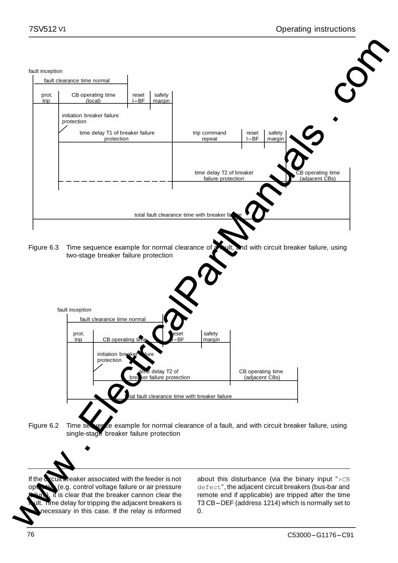
Operating instructions7SV512 V1
C53000---G1176---C9176
fault inception
fault clearance time normal
prot.trip
initiation breaker failureprotection
time delay T1 of breaker failureprotection
CB operating time(adjacent CBs)
total fault clearance time with breaker failure
trip commandrepeat
safetymargin
resetI---BF
CB operating time(local)
safetymargin
resetI---BF
time delay T2 of breakerfailure protection
Figure 6.3 Time sequence example for normal clearance of a fault, and with circuit breaker failure, usingtwo-stage breaker failure protection
fault inception
fault clearance time normal
prot. reset safetytrip CB operating time I---BF margin
initiation breaker failureprotection
time delay T2 of CB operating timebreaker failure protection (adjacent CBs)
total fault clearance time with breaker failure
Figure 6.2 Time sequence example for normal clearance of a fault, and with circuit breaker failure, usingsingle-stage breaker failure protection
If the circuit breaker associated with the feeder is notoperative (e.g. control voltage failure or air pressurefailure), it is clear that the breaker cannon clear thefault. Time delay for tripping the adjacent breakers isnot necessary in this case. If the relay is informed
about this disturbance (via the binary input ”>CBdefect”, the adjacent circuit breakers (bus-bar andremote end if applicable) are tripped after the timeT3 CB---DEF (address 1214) which is normally set to0.www .
Elec
tricalP
artM
anua
ls . c
om

Operating instructions7SV512 V1
77C53000---G1176---C91
1 2 0 0 B R E A K E R
F A I L U R E P R O T .
Beginning of the block ”Circuit breaker failure protec-tion”
1 2 0 1 B R E A K F A I L
O N
O F F
Circuit breaker failure protection is
ON switched on
OFF switched off
Pick-up value of the current detector of the breakerfailure protectionSmallest setting value: 0.05 INLargest setting value: 4.00 IN
1 2 0 2 I - B F
0 . 1 0 I / I n
1 2 0 3 T R I P C R o f f
N O
Y E S
Trip signal repetition to the local feeder circuit breaker(cross trip) is switched offNO after T1 (two-stage breaker failure protection)
cross trip will be initiatedYES cross trip is switched off (single-stage breaker
failure protection)
1 2 0 4 T R I P 1 P O L E
Y E S
N O
Single-pole trip signal repetition to the local feederbreaker after single-pole trip of the feeder protectionYES is permitted provided the feeder protection has
issued a single-pole trip signalNO is not permitted: always three-pole trip by the
breaker failure protection
Delay time for trip signal repetition to the local feederbreaker after single-pole trip command of the feederprotectionSmallest setting value: 0.00 sLargest setting value: 32.00 sor 1, i.e. no trip in this case
1 2 0 5 T 1 - 1 P O L E
0 . 0 0 s
Delay time for trip signal repetition to the local feederbreaker after three-pole trip command of the feederprotectionSmallest setting value: 0.00 sLargest setting value: 32.00 sor 1, i.e. no trip in this case
1 2 0 6 T 1 - 3 P O L E
0 . 0 0 s
1 2 1 1 T - T R I P - B B
T 1 + T 2
T 2
The total delay time of the trip signal to the adjacentcircuit breakers (bus-bar zone and remote end if appli-cable)T1+T2 is composed of T1 (address 1205 or 1206)
and T2 (address 1212 or 1213); i.e. T2 isstarted after expiry of T1
T2 is equal T2 (address 1212 or 1213); i.e. T2is started with trip command of the feederprotectionwww .
Elec
tricalP
artM
anua
ls . c
om

Operating instructions7SV512 V1
C53000---G1176---C9178
Delay time of the trip signal to the adjacent breakers(bus-bar and, if applicable, remote end) if current flow(address 1202) is breaker failure criterionSmallest setting value: 0.00 sLargest setting value: 32.00 sor 1, i.e. no trip in this case
1 2 1 2 T 2 - C U R R E N T
0 . 1 5 s
Delay time of the trip signal to the adjacent breakers(bus-bar and, if applicable, remote end) if breaker aux-iliary contacts are the breaker failure criterionSmallest setting value: 0.00 sLargest setting value: 32.00 sor 1, i.e. no trip in this case
1 2 1 3 T 2 C B - A U X .
0 . 1 5 s
Delay time of the bus-trip signal to the adjacent break-ers (bus-bar and, if applicable, remote end) if the localfeeder breaker is defectiveSmallest setting value: 0.00 sLargest setting value: 32.00 sor 1, i.e. no trip in this case
1 2 1 4 T 3 C B - D E F .
0 . 0 0 s
The delay time of the end fault protection is set underaddress 1220. An end fault is a short-circuit betweenthe circuit breaker and the current transformer set ofthe feeder.
If, during an end fault, the circuit breaker is trippedby a reverse fault stage of the feeder protection or bythe bus-bar protection (the fault is a bus-bar fault asdetermined from the location of the current trans-formers), the fault current will continue, because it isfed from the remote end of the feeder circuit.
The time T---ENDFAULT (address 1220) is startedwhen, during fault detection conditions of the feederprotection, the circuit breaker auxiliary contacts indi-cate open poles and, at the same time, current flowis detected (address 1202). The trip command of theend fault protection is intended for the transmissionof an intertrip signal to the remote end circuit break-er.
Thus, the delay time is set such that it can bridge outshort transient end fault conditions which may occurduring switching of the breaker.
Delay time for end faults until trip signal for transmis-sion to the remote end is generatedSmallest setting value: 0.00 sLargest setting value: 32.00 sor 1, i.e. no trip in this case
1 2 2 0 T - E N D F A U L T
0 . 1 0 s
In order to meet the high safety requirement of thecircuit breaker failure protection, comprehensivemonitoring facilities and plausibility checks havebeen incorporated to the 7SV512 relay. For detailsrefer to Section 4.2.7.
A pre-condition for the correct operation of some of
these monitoring and plausibility check functions is,that the relay is connected according to a certainconnection scheme. If the binary inputs and outputsare assigned as delivered and if the relay is con-nected according the connection diagram in Appen-dix B, all check functions are optimized to matcheach other and the safety requirements.
www . El
ectric
alPar
tMan
uals
. com
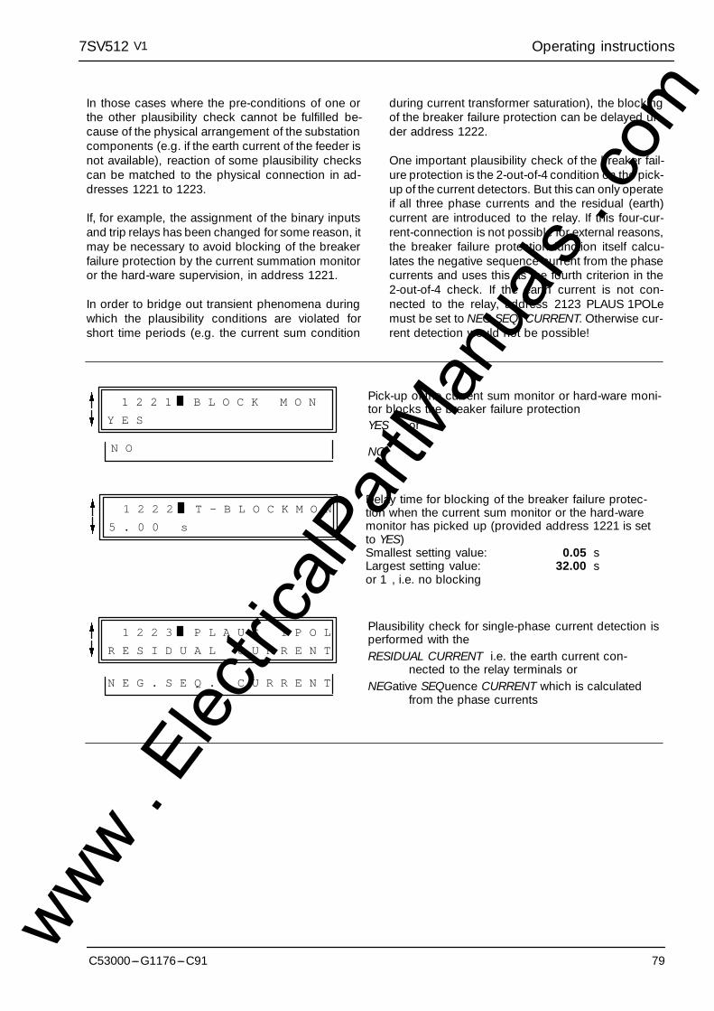
Operating instructions7SV512 V1
79C53000---G1176---C91
In those cases where the pre-conditions of one orthe other plausibility check cannot be fulfilled be-cause of the physical arrangement of the substationcomponents (e.g. if the earth current of the feeder isnot available), reaction of some plausibility checkscan be matched to the physical connection in ad-dresses 1221 to 1223.
If, for example, the assignment of the binary inputsand trip relays has been changed for some reason, itmay be necessary to avoid blocking of the breakerfailure protection by the current summation monitoror the hard-ware supervision, in address 1221.
In order to bridge out transient phenomena duringwhich the plausibility conditions are violated forshort time periods (e.g. the current sum condition
during current transformer saturation), the blockingof the breaker failure protection can be delayed un-der address 1222.
One important plausibility check of the breaker fail-ure protection is the 2-out-of-4 condition on the pick-up of the current detectors. But this can only operateif all three phase currents and the residual (earth)current are introduced to the relay. If this four-cur-rent-connection is not possible for external reasons,the breaker failure protection function itself calcu-lates the negative sequence current from the phasecurrents and uses this as the fourth criterion in the2-out-of-4 check. If the earth current is not con-nected to the relay, address 2123 PLAUS 1POLemust be set to NEG.SEQ. CURRENT. Otherwise cur-rent detection would not be possible!
1 2 2 1 B L O C K M O N
Y E S
N O
Pick-up of the current sum monitor or hard-ware moni-tor blocks the breaker failure protectionYES or
NO
Delay time for blocking of the breaker failure protec-tion when the current sum monitor or the hard-waremonitor has picked up (provided address 1221 is setto YES)Smallest setting value: 0.05 sLargest setting value: 32.00 sor 1, i.e. no blocking
1 2 2 2 T - B L O C K M O N
5 . 0 0 s
1 2 2 3 P L A U S 1 P O L
R E S I D U A L C U R R E N T
N E G . S E Q . C U R R E N T
Plausibility check for single-phase current detection isperformed with theRESIDUAL CURRENT i.e. the earth current con-
nected to the relay terminals orNEGative SEQuence CURRENT which is calculated
from the phase currents
www . El
ectric
alPar
tMan
uals
. com
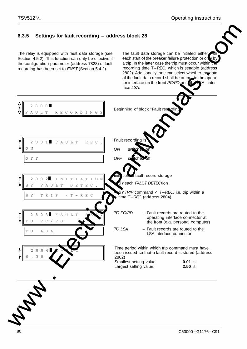
Operating instructions7SV512 V1
C53000---G1176---C9180
6.3.5 Settings for fault recording --- address block 28
The relay is equipped with fault data storage (seeSection 4.5.2). This function can only be effective ifthe configuration parameter (address 7828) of faultrecording has been set to EXIST (Section 5.4.2).
The fault data storage can be initiated either witheach start of the breaker failure protection or only bya trip. In the latter case the trip must occur within therecording time T---REC, which is settable (address2802). Additionally, one can select whether the dataof the fault data record shall be output to the opera-tor interface on the front PC/PD or to the LSA--- inter-face LSA.
2 8 0 0
F A U L T R E C O R D I N G SBeginning of block ”Fault recordings”
2 8 0 1 F A U L T R E C .
O N
O F F
Fault recording is
ON switched on
OFF switched off
2 8 0 2 I N I T I A T I O N
B Y F A U L T D E T E C .
B Y T R I P < T - R E C
Initiation of fault record storage
--- BY each FAULT DETECtion
--- BY TRIP command < T---REC, i.e. trip within atime T---REC (address 2804)
2 8 0 3 F A U L T R E C .
T O P C / P D
T O L S A
TO PC/PD --- Fault records are routed to theoperating interface connector atthe front (e.g. personal computer)
TO LSA --- Fault records are routed to theLSA interface connector
2 8 0 4 T - R E C
0 . 3 0 s
Time period within which trip command must havebeen issued so that a fault record is stored (address2802)Smallest setting value: 0.01 sLargest setting value: 2.50 s
www . El
ectric
alPar
tMan
uals
. com
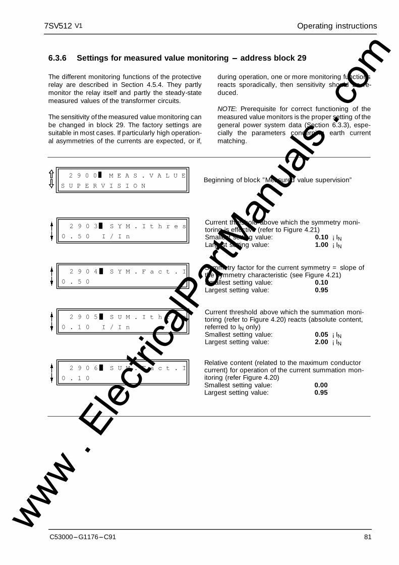
Operating instructions7SV512 V1
81C53000---G1176---C91
6.3.6 Settings for measured value monitoring --- address block 29
The different monitoring functions of the protectiverelay are described in Section 4.5.4. They partlymonitor the relay itself and partly the steady-statemeasured values of the transformer circuits.
The sensitivity of the measured value monitoring canbe changed in block 29. The factory settings aresuitable in most cases. If particularly high operation-al asymmetries of the currents are expected, or if,
during operation, one or more monitoring functionsreacts sporadically, then sensitivity should be re-duced.
NOTE: Prerequisite for correct functioning of themeasured value monitors is the proper setting of thegeneral power system data (Section 6.3.3), espe-cially the parameters concerning earth currentmatching.
2 9 0 0 M E A S . V A L U E
S U P E R V I S I O NBeginning of block ”Measured value supervision”
2 9 0 3 S Y M . I t h r e s
0 . 5 0 I / I n
Current threshold above which the symmetry moni-toring is effective (refer to Figure 4.21)Smallest setting value: 0.10 ¡ INLargest setting value: 1.00 ¡ IN
2 9 0 4 S Y M . F a c t . I
0 . 5 0
Symmetry factor for the current symmetry = slope ofthe symmetry characteristic (see Figure 4.21)Smallest setting value: 0.10Largest setting value: 0.95
2 9 0 5 S U M . I t h r e s
0 . 1 0 I / I n
Current threshold above which the summation moni-toring (refer to Figure 4.20) reacts (absolute content,referred to IN only)Smallest setting value: 0.05 ¡ INLargest setting value: 2.00 ¡ IN
2 9 0 6 S U M . F a c t . I
0 . 1 0
Relative content (related to the maximum conductorcurrent) for operation of the current summation mon-itoring (refer Figure 4.20)Smallest setting value: 0.00Largest setting value: 0.95
www . El
ectric
alPar
tMan
uals
. com
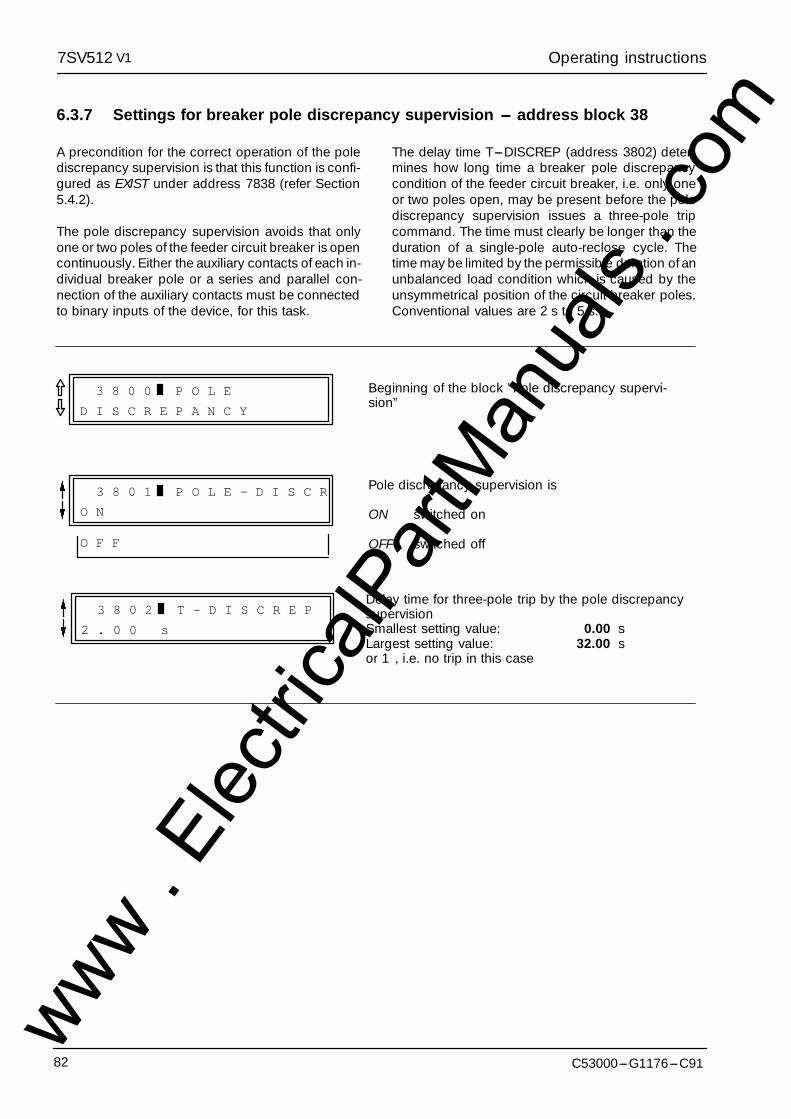
Operating instructions7SV512 V1
C53000---G1176---C9182
6.3.7 Settings for breaker pole discrepancy supervision --- address block 38
A precondition for the correct operation of the polediscrepancy supervision is that this function is confi-gured as EXIST under address 7838 (refer Section5.4.2).
The pole discrepancy supervision avoids that onlyone or two poles of the feeder circuit breaker is opencontinuously. Either the auxiliary contacts of each in-dividual breaker pole or a series and parallel con-nection of the auxiliary contacts must be connectedto binary inputs of the device, for this task.
The delay time T---DISCREP (address 3802) deter-mines how long time a breaker pole discrepancycondition of the feeder circuit breaker, i.e. only oneor two poles open, may be present before the polediscrepancy supervision issues a three-pole tripcommand. The time must clearly be longer than theduration of a single-pole auto-reclose cycle. Thetime may be limited by the permissible duration of anunbalanced load condition which is caused by theunsymmetrical position of the circuit breaker poles.Conventional values are 2 s to 5 s.
3 8 0 0 P O L E
D I S C R E P A N C Y
Beginning of the block ”Pole discrepancy supervi-sion”
3 8 0 1 P O L E - D I S C R
O N
O F F
Pole discrepancy supervision is
ON switched on
OFF switched off
Delay time for three-pole trip by the pole discrepancysupervisionSmallest setting value: 0.00 sLargest setting value: 32.00 sor 1, i.e. no trip in this case
3 8 0 2 T - D I S C R E P
2 . 0 0 s
www . El
ectric
alPar
tMan
uals
. com
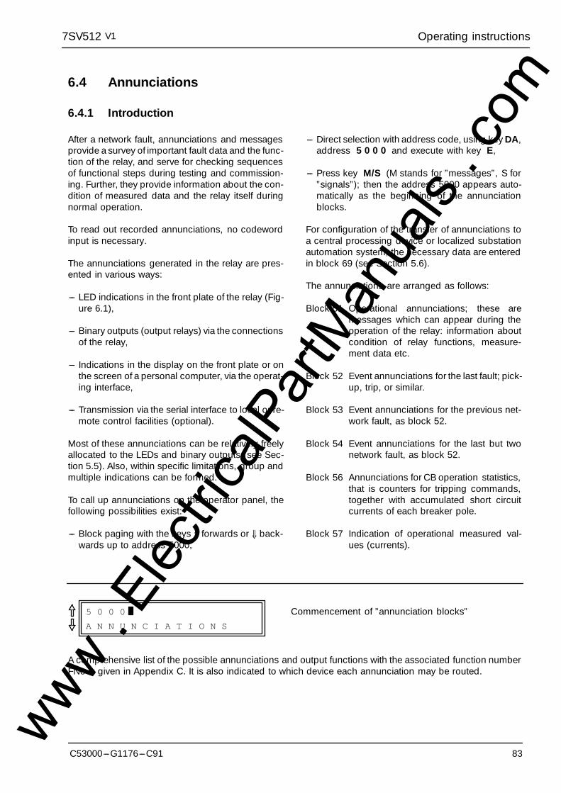
Operating instructions7SV512 V1
83C53000---G1176---C91
6.4 Annunciations
6.4.1 Introduction
After a network fault, annunciations and messagesprovide a survey of important fault data and the func-tion of the relay, and serve for checking sequencesof functional steps during testing and commission-ing. Further, they provide information about the con-dition of measured data and the relay itself duringnormal operation.
To read out recorded annunciations, no codewordinput is necessary.
The annunciations generated in the relay are pres-ented in various ways:
--- LED indications in the front plate of the relay (Fig-ure 6.1),
--- Binary outputs (output relays) via the connectionsof the relay,
--- Indications in the display on the front plate or onthe screen of a personal computer, via the operat-ing interface,
--- Transmission via the serial interface to local or re-mote control facilities (optional).
Most of these annunciations can be relatively freelyallocated to the LEDs and binary outputs (see Sec-tion 5.5). Also, within specific limitations, group andmultiple indications can be formed.
To call up annunciations on the operator panel, thefollowing possibilities exist:
--- Block paging with the keys ⇑ forwards or ⇓ back-wards up to address 5000,
--- Direct selection with address code, using key DA,address 5 0 0 0 and execute with key E,
--- Press key M/S (M stands for ”messages”, S for”signals”); then the address 5000 appears auto-matically as the beginning of the annunciationblocks.
For configuration of the transfer of annunciations toa central processing device or localized substationautomation system, the necessary data are enteredin block 69 (see Section 5.6).
The annunciations are arranged as follows:
Block 51 Operational annunciations; these aremessages which can appear during theoperation of the relay: information aboutcondition of relay functions, measure-ment data etc.
Block 52 Event annunciations for the last fault; pick-up, trip, or similar.
Block 53 Event annunciations for the previous net-work fault, as block 52.
Block 54 Event annunciations for the last but twonetwork fault, as block 52.
Block 56 Annunciations for CB operation statistics,that is counters for tripping commands,together with accumulated short circuitcurrents of each breaker pole.
Block 57 Indication of operational measured val-ues (currents).
5 0 0 0
A N N U N C I A T I O N S
Commencement of ”annunciation blocks”
A comprehensive list of the possible annunciations and output functions with the associated function numberFNo is given in Appendix C. It is also indicated to which device each annunciation may be routed.
www . El
ectric
alPar
tMan
uals
. com

Operating instructions7SV512 V1
C53000---G1176---C9184
6.4.2 Operational annunciations --- address block 51
Operational and status annunciations contain infor-mation which the unit provides during operation andabout the operation. They begin at address 5100.Important events and status changes are chrono-logically listed, starting with the most recent mes-sage. Time information is shown in hours and min-utes. Up to 50 operational indications can be stored.If more occur, the oldest are erased in sequence.
Faults in the network are only indicated as ”SystemFlt” together with the sequence number of thefault. Detailed information about the history of thefault is contained in blocks ”Fault annunciations”; re-fer Section 6.4.3.
The input of the codeword is not required.
After selection of the address 5100 (by direct selec-tion with DA 5 1 0 0 E and/or paging with ⇑ or ⇓and further scrolling " or #) the operational annunci-ations appear. The boxes below show all availableoperational annunciations. In each specific case, ofcourse, only the associated annunciations appear inthe display.
Next to the boxes below, the abbreviated forms areexplained. It is indicated whether an event is an-nounced on occurrence (C = ”Coming”) or a statusis announced ”Coming” and ”Going” (C/G).
The first listed message is, as example, assignedwith date and time in the first line; the second lineshows the beginning of a condition with the charac-ter C to indicate that this condition occurred at thedisplayed time.
5 1 0 0 O P E R A T I O N A L
A N N U N C I A T I O N S
Beginning of the block ”Operationalannunciations”
1st line:Date and time of the event or statuschange
2nd line: Annunciation text, in the example Coming
2 8 . 0 7 . 9 3 1 2 : 4 3
L E D r e s e t : C
If the real time clock is not available the date is replaced by KK.KK.KK, the time is given as relative time from thelast re-start of the processor system.
Direct response from binary inputs:
> S t a r t F l t R e c Fault recording started via binary input (C)
> C B A u x . L 1 Circuit breaker auxiliary contact pole L1 closed (C/G)
> C B A u x . L 2 Circuit breaker auxiliary contact pole L2 closed (C/G)
> C B A u x . L 3 Circuit breaker auxiliary contact pole L3 closed (C/G)
> C B A u x . 3 p C Circuit breaker auxiliary contact all poles closed (C/G)
> C B A u x . 1 p C Circuit breaker auxiliary contact any pole closed (C/G)
www . El
ectric
alPar
tMan
uals
. com

Operating instructions7SV512 V1
85C53000---G1176---C91
> A n n u n c . 1 User defined annunciation No 1 received via binaryinput (C/G)
> A n n u n c . 2 User defined annunciation No 2 received via binaryinput (C/G)
> A n n u n c . 3 User defined annunciation No 3 received via binaryinput (C/G)
> A n n u n c . 4 User defined annunciation No 4 received via binaryinput (C/G)
> S t a r t General fault detection signal from a main protectionrelay for beaker failure protection (C/G)
> S t a r t N Earth fault detection signal from a main protectionrelay for beaker failure protection (C/G)
> T r i p General trip signal from a main protection relay forbeaker failure protection (C/G)
> T r i p 3 p o l e Three-pole trip signal from a main protection relay forbeaker failure protection (C/G)
> T r i p L 1 Trip signal for pole L1 from a main protection relay forbeaker failure protection (C/G)
> T r i p L 2 Trip signal for pole L2 from a main protection relay forbeaker failure protection (C/G)
> T r i p L 3 Trip signal for pole L3 from a main protection relay forbeaker failure protection (C/G)
> B / F b l o c k Breaker failure protection blocked via binary input(C/G)
> C B d e f e c t Circuit breaker defective (from external breaker moni-tor) (C/G)
General operational annunciations of the protection device:
R e - s t a r t Re-start annunciation of the processor system (C)
S y s t . F l t Network fault (C), detailed information in the fault an-nunciations
L E D r e s e t Stored LED indications reset (C)
F l t . R e c . o f f Fault recording switched off (C/G)
P a r a m . R u n n i n g Parameters are being set (C/G)
P a r a m . S e t A Parameter set A is active (C/G)
P a r a m . S e t B Parameter set B is active (C/G)
P a r a m . S e t C Parameter set C is active (C/G)
P a r a m . S e t D Parameter set D is active (C/G)
www . El
ectric
alPar
tMan
uals
. com

Operating instructions7SV512 V1
C53000---G1176---C9186
Annunciations of monitoring functions:
F a i l u r e 1 8 V Failure in internal supply voltage 18 V (C/G)
F a i l u r e 1 5 V Failure in internal supply voltage 15 V (C/G)
F a i l u r e 5 V Failure in internal supply voltage 5 V (C/G)
F a i l u r e 0 V Failure in offset voltage 0 V (C/G)
F a i l u r e R K A Failure on input/output module RKA (C/G)
A n n u n c . L o s t Annunciations lost (buffer overflow) (C)
F l t . B u f f . O v e r Buffer for fault annunciations overflow (C)
F l t . F l a g O v e r Buffer of fault flags overflow (C)
O p e r . A n n . I n v Operational annunciations invalid (C)
F a u l t . A n n . I n v Fault annunciations invalid (C)
A n n u n c . I n v a l . Annunciations invalid (C/G)
S t a t . B u f f . I n v Buffer for operation statistics invalid (C/G)
L E D B u f f . I n v a Buffer for stored LEDs invalid (C/G)
F a i l u r e I Failure detected by current plausibility monitor I (C/G)
F a i l u r e I s y m m Failure detected by current symmetry monitor(C/G)
C h s . E r r o r Check-sum error detected (C/G)
C h s . S 1 E r r o r Check-sum error detected for parameter set A:no operation possible with this set (C/G)
C h s . S 2 E r r o r Check-sum error detected for parameter Set B:no operation possible with this set (C/G)
C h s . S 3 E r r o r Check-sum error detected for parameter set C:no operation possible with this set (C/G)
C h s . S 4 E r r o r Check-sum error detected for parameter set D:no operation possible with this set (C/G)
www . El
ectric
alPar
tMan
uals
. com
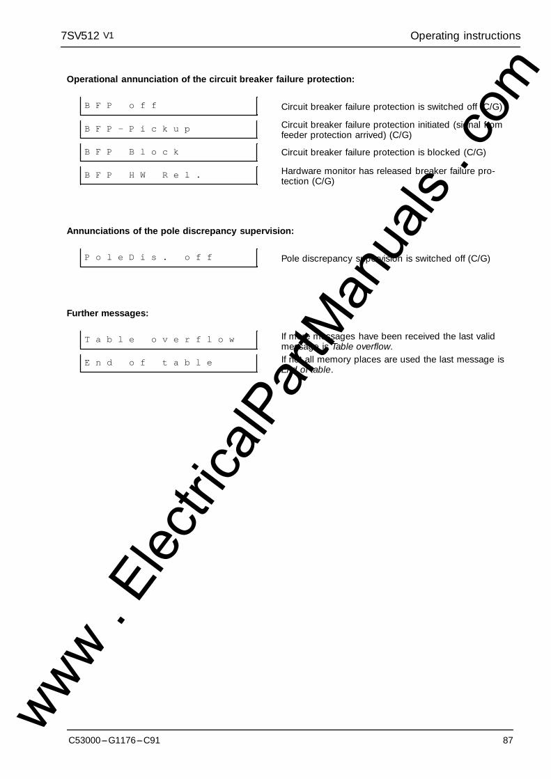
Operating instructions7SV512 V1
87C53000---G1176---C91
Operational annunciation of the circuit breaker failure protection:
B F P o f f Circuit breaker failure protection is switched off (C/G)
B F P - P i c k u p Circuit breaker failure protection initiated (signal fromfeeder protection arrived) (C/G)
B F P B l o c k Circuit breaker failure protection is blocked (C/G)
B F P H W R e l . Hardware monitor has released breaker failure pro-tection (C/G)
Annunciations of the pole discrepancy supervision:
P o l e D i s . o f f Pole discrepancy supervision is switched off (C/G)
Further messages:
T a b l e o v e r f l o w If more messages have been received the last validmessage is Table overflow.
E n d o f t a b l e If not all memory places are used the last message isEnd of table.
www . El
ectric
alPar
tMan
uals
. com
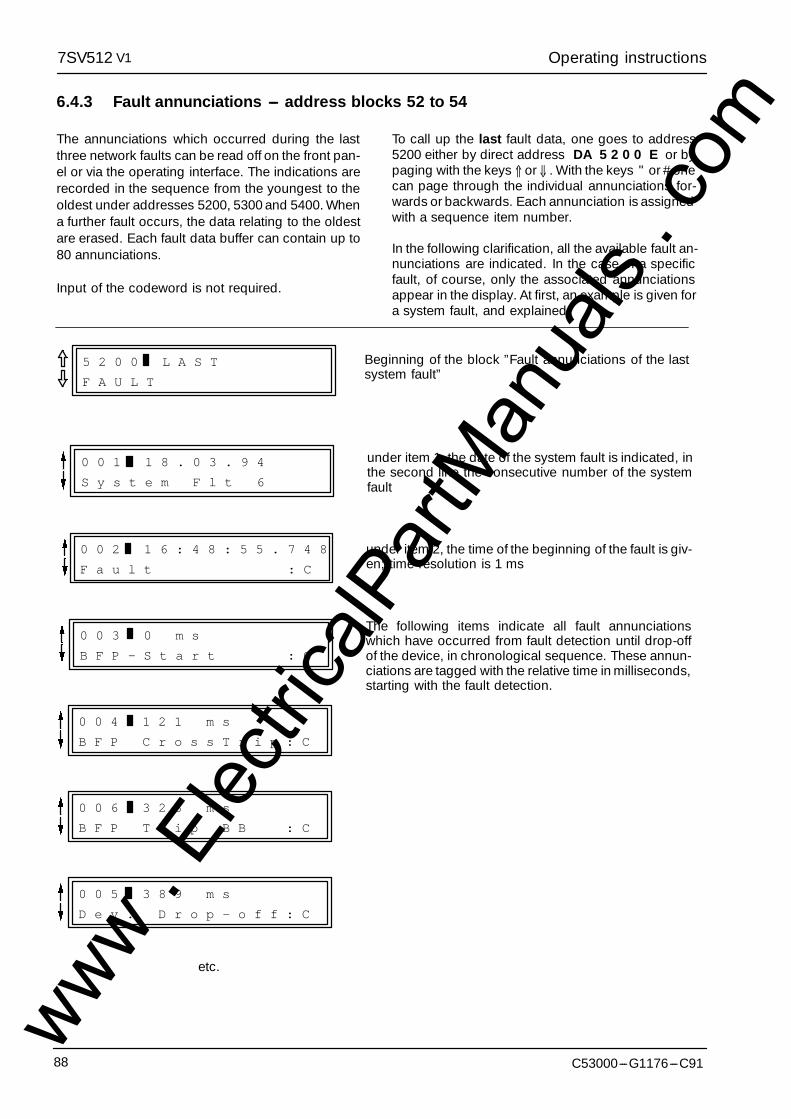
Operating instructions7SV512 V1
C53000---G1176---C9188
6.4.3 Fault annunciations --- address blocks 52 to 54
The annunciations which occurred during the lastthree network faults can be read off on the front pan-el or via the operating interface. The indications arerecorded in the sequence from the youngest to theoldest under addresses 5200, 5300 and 5400. Whena further fault occurs, the data relating to the oldestare erased. Each fault data buffer can contain up to80 annunciations.
Input of the codeword is not required.
To call up the last fault data, one goes to address5200 either by direct address DA 5 2 0 0 E or bypaging with the keys ⇑ or ⇓ . With the keys " or # onecan page through the individual annunciations for-wards or backwards. Each annunciation is assignedwith a sequence item number.
In the following clarification, all the available fault an-nunciations are indicated. In the case of a specificfault, of course, only the associated annunciationsappear in the display. At first, an example is given fora system fault, and explained.
5 2 0 0 L A S T
F A U L T
Beginning of the block ”Fault annunciations of the lastsystem fault”
0 0 1 1 8 . 0 3 . 9 4
S y s t e m F l t 6
under item 1, the date of the system fault is indicated, inthe second line the consecutive number of the systemfault
0 0 2 1 6 : 4 8 : 5 5 . 7 4 8
F a u l t : C
under item 2, the time of the beginning of the fault is giv-en; time resolution is 1 ms
0 0 3 0 m s
B F P - S t a r t : C
The following items indicate all fault annunciationswhich have occurred from fault detection until drop-offof the device, in chronological sequence. These annun-ciations are tagged with the relative time in milliseconds,starting with the fault detection.
0 0 4 1 2 1 m s
B F P C r o s s T r i p : C
0 0 6 3 2 3 m s
B F P T r i p B B : C
0 0 5 3 8 9 m s
D e v . D r o p - o f f : C
etc.
www . El
ectric
alPar
tMan
uals
. com

Operating instructions7SV512 V1
89C53000---G1176---C91
General fault annunciations of the device:
S y s t . F l t System fault with consecutive number
F a u l t Beginning of fault
I L 1 / I n = Interrupted fault current of phase L1
I L 2 / I n = Interrupted fault current of phase L2
I L 3 / I n = Interrupted fault current of phase L3
D e v . D r o p - o f f Drop-off of the device, general
Annunciations of circuit breaker failure protection:
B F P B l o c k Breaker failure protection blocked (during fault)
B F P - S t a r t Initiation of breaker failure protection
B F P - S t a r t . L 1 Initiation of breaker failure protection, CB pole L1
B F P - S t a r t . L 2 Initiation of breaker failure protection, CB pole L2
B F P - S t a r t . L 3 Initiation of breaker failure protection, CB pole L3
B F P T 1 3 p o l e Delay time T1 after three-pole trip expired
B F P T 1 1 p o l e Delay time T1 after single-pole trip expired
B F P T 2 C u r r Delay time T2 with current criterion expired
B F P T 2 B a u x Delay time T2 with CB auxiliary contact criterion ex-pired
B F P T 3 B R d e f Delay time with defective circuit breaker expired
B F P T e n d F a u l Delay time for end fault protection expired
B F P T r i p L 1 Trip by breaker failure protection caused by failure inpole L1 (1st stage)
B F P T r i p L 2 Trip by breaker failure protection caused by failure inpole L2 (1st stage)
B F P T r i p L 3 Trip by breaker failure protection caused by failure inpole L3 (1st stage)
B F P T r i p L 1 2 3 Trip by breaker failure protection three-pole (1ststage)
B F P C r o s s T r i p Trip by breaker failure protection on the local feedercircuit breaker (1st stage)
B F P T r i p B B Trip by breaker failure protection to the bus-barbreakers (2nd stage)
B / F T r a n s T r i p Transfer trip signal of breaker failure protectionwww . El
ectric
alPar
tMan
uals
. com
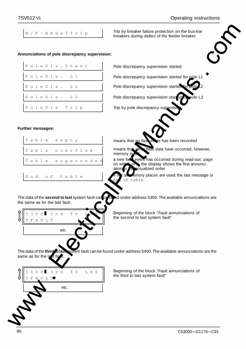
Operating instructions7SV512 V1
C53000---G1176---C9190
B / F - B R d e f T r i p Trip by breaker failure protection on the bus-barbreakers during defect of the feeder breaker
Annunciations of pole discrepancy supervision:
P o l e D i s . S t a r t Pole discrepancy supervision started
P o l e D i s . L 1 Pole discrepancy supervision started for pole L1
P o l e D i s . L 2 Pole discrepancy supervision started for pole L2
P o l e D i s . L 3 Pole discrepancy supervision started for pole L3
P o l e D i s T r i p Trip by pole discrepancy supervision
Further messages:
T a b l e e m p t y means that no fault event has been recorded
T a b l e o v e r f l o w means that other fault data have occurred, however,memory is full
T a b l e s u p e r c e d e d a new fault event has occurred during read-out: pageon with " or #; the display shows the first annunci-ation in the actualized order
E n d o f t a b l e If not all memory places are used the last message isEnd of table.
The data of the second to last system fault can be found under address 5300. The available annunciations arethe same as for the last fault.
5 3 0 0 2 n d T O L A S
T F A U L T
Beginning of the block ”Fault annunciations ofthe second to last system fault”
etc.
The data of the third to last system fault can be found under address 5400. The available annunciations are thesame as for the last fault.
5 4 0 0 3 r d T O L A S
T F A U L T
Beginning of the block ”Fault annunciations ofthe third to last system fault”
etc.
www . El
ectric
alPar
tMan
uals
. com
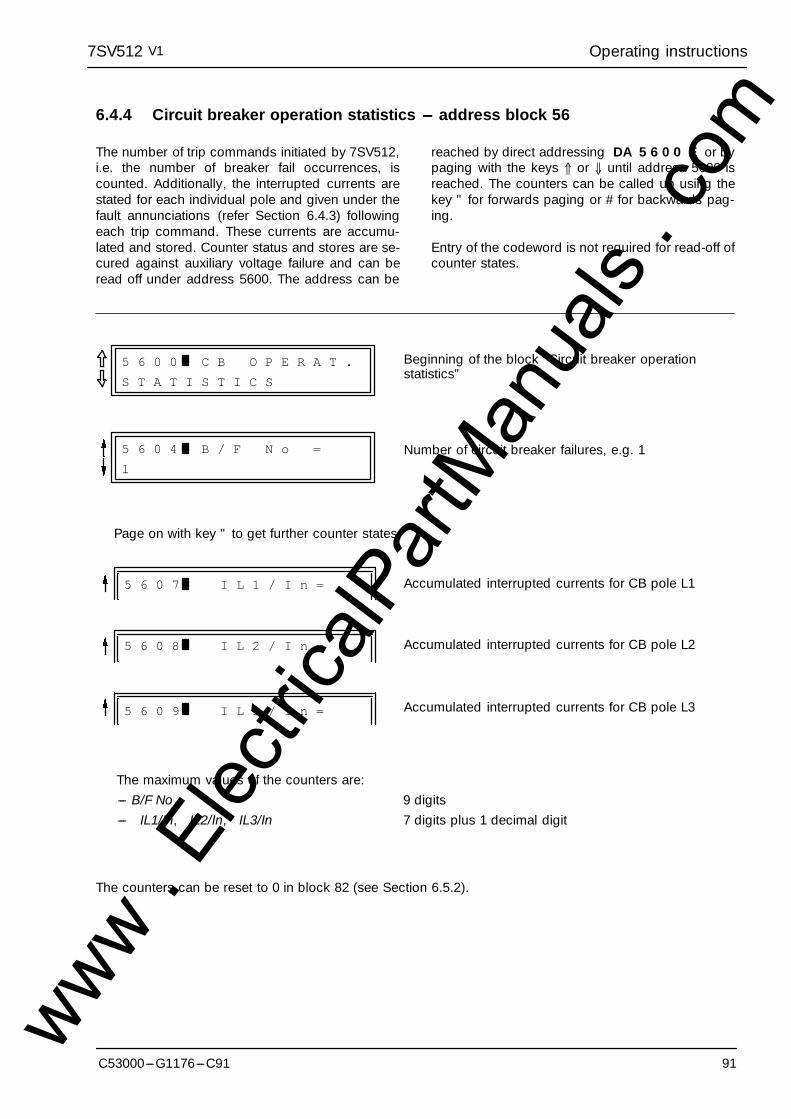
Operating instructions7SV512 V1
91C53000---G1176---C91
6.4.4 Circuit breaker operation statistics --- address block 56
The number of trip commands initiated by 7SV512,i.e. the number of breaker fail occurrences, iscounted. Additionally, the interrupted currents arestated for each individual pole and given under thefault annunciations (refer Section 6.4.3) followingeach trip command. These currents are accumu-lated and stored. Counter status and stores are se-cured against auxiliary voltage failure and can beread off under address 5600. The address can be
reached by direct addressing DA 5 6 0 0 E or bypaging with the keys ⇑ or ⇓ until address 5600 isreached. The counters can be called up using thekey " for forwards paging or # for backwards pag-ing.
Entry of the codeword is not required for read-off ofcounter states.
5 6 0 0 C B O P E R A T .
S T A T I S T I C S
Beginning of the block ”Circuit breaker operationstatistics”
Number of circuit breaker failures, e.g. 1
Accumulated interrupted currents for CB pole L1
Accumulated interrupted currents for CB pole L2
Accumulated interrupted currents for CB pole L3
5 6 0 4 B / F N o =
1
Page on with key " to get further counter states
The maximum values of the counters are:--- B/F No 9 digits--- IL1/In, IL2/In, IL3/In 7 digits plus 1 decimal digit
5 6 0 7 I L 1 / I n =
5 6 0 8 I L 2 / I n =
5 6 0 9 I L 3 / I n =
The counters can be reset to 0 in block 82 (see Section 6.5.2).
www . El
ectric
alPar
tMan
uals
. com
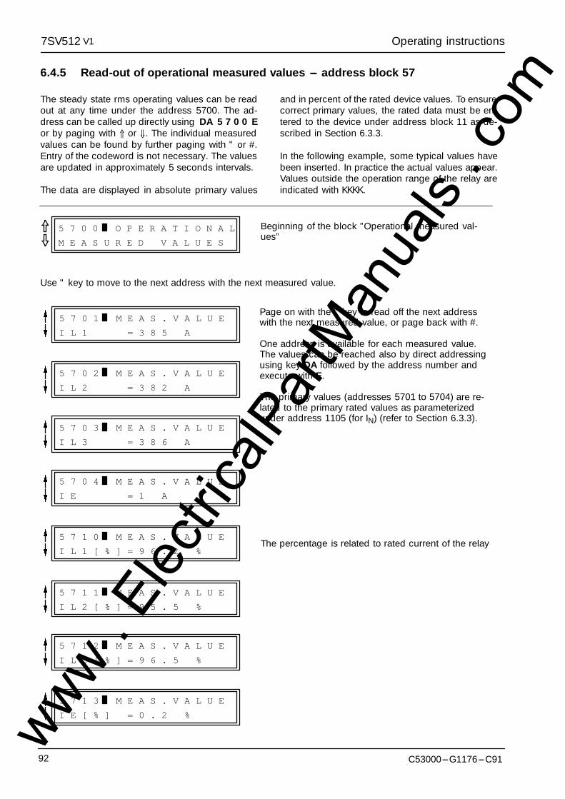
Operating instructions7SV512 V1
C53000---G1176---C9192
6.4.5 Read-out of operational measured values --- address block 57
The steady state rms operating values can be readout at any time under the address 5700. The ad-dress can be called up directly using DA 5 7 0 0 Eor by paging with ⇑ or ⇓. The individual measuredvalues can be found by further paging with " or #.Entry of the codeword is not necessary. The valuesare updated in approximately 5 seconds intervals.
The data are displayed in absolute primary values
and in percent of the rated device values. To ensurecorrect primary values, the rated data must be en-tered to the device under address block 11 as de-scribed in Section 6.3.3.
In the following example, some typical values havebeen inserted. In practice the actual values appear.Values outside the operation range of the relay areindicated with KKKK.
5 7 0 0 O P E R A T I O N A L
M E A S U R E D V A L U E S
Beginning of the block ”Operational measured val-ues”
Use " key to move to the next address with the next measured value.
5 7 0 1 M E A S . V A L U E
I L 1 = 3 8 5 A
Page on with the " key to read off the next addresswith the next measured value, or page back with #.
One address is available for each measured value.The values can be reached also by direct addressingusing key DA followed by the address number andexecute with E.
The primary values (addresses 5701 to 5704) are re-lated to the primary rated values as parameterizedunder address 1105 (for IN) (refer to Section 6.3.3).
The percentage is related to rated current of the relay
5 7 0 2 M E A S . V A L U E
I L 2 = 3 8 2 A
5 7 0 3 M E A S . V A L U E
I L 3 = 3 8 6 A
5 7 0 4 M E A S . V A L U E
I E = 1 A
5 7 1 0 M E A S . V A L U E
I L 1 [ % ] = 9 6 . 2 %
5 7 1 1 M E A S . V A L U E
I L 2 [ % ] = 9 5 . 5 %
5 7 1 2 M E A S . V A L U E
I L 3 [ % ] = 9 6 . 5 %
5 7 1 3 M E A S . V A L U E
I E [ % ] = 0 . 2 %www . El
ectric
alPar
tMan
uals
. com

Operating instructions7SV512 V1
93C53000---G1176---C91
6.5 Operational control facilities
During operation of the protection relay it may be de-sired to intervene in functions or annunciations man-ually or from system conditions. The 7SV512 con-tains facilities, e.g. to re-adjust the real time clock, toerase stored information and event counters, toswitch on or off partial functions under specific con-ditions, or to change over preselected sets of func-tion parameters.
The functions can be controlled from the operatingpanel on the front of the device, via the operating in-terface on the front as well as via binary inputs.
In order to control functions via binary inputs it is
necessary that the binary inputs are marshalled tothe corresponding switching functions during instal-lation of the device and that they are connected ac-cordingly (refer to Section 5.5.2 Marshalling of thebinary inputs).
The control facilities begin with address block 8000.This address is reached
--- by block paging with the keys ⇑ forwards or ⇓backwards up to address 8000, or
--- by direct selection with address code, using keyDA, address 8 0 0 0 and execute with key E.
8 0 0 0 D E V I C E
C O N T R O LBeginning of the block ”Device control”
6.5.1 Adjusting and synchronizing the real time clock --- address block 81
The date and time can be adjusted at any time dur-ing operation as long as the real time clock is opera-tive. Setting is carried out in block 81 which isreached by direct addressing DA 8 1 0 0 E or bypaging with ⇑ and ⇓. Input of the codeword is re-quired to change the data.
Selection of the individual addresses is by furtherscrolling using " # as shown below. Each modifica-tion must be confirmed with the enter key E.
2 1 . 0 3 . 1 9 9 4
1 1 : 3 1 : 3 1
8 1 0 0 S E T T I N G
R E A L T I M E C L O C KBeginning of the block ”Setting the real time clock”.Continue with ".
At first, the actual date and time are displayed.Continue with ".
8 1 0 2 D A T EEnter the new date: 2 digits for day, 2 digits for monthand 4 digits for year (including century); use the formatas configured under address 7003 (Section 5.3.2), butalways use a dot as separator:DD.MM.YYYY or MM.DD.YYYY
8 1 0 3 T I M E Enter the new time: hours, minutes, seconds, eachwith 2 digits, separated by a dot:HH.MM.SS
8 1 0 4 D I F F . T I M EUsing the difference time setting, the clock is set for-wards by the entered time, or backwards using the+/--- key. The format is the same as with the time set-ting above.www .
Elec
tricalP
artM
anua
ls . c
om
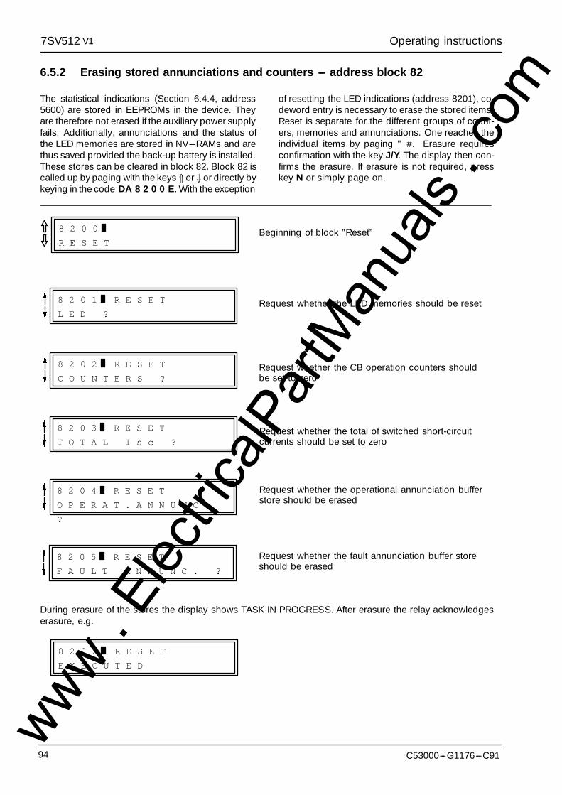
Operating instructions7SV512 V1
C53000---G1176---C9194
6.5.2 Erasing stored annunciations and counters --- address block 82
The statistical indications (Section 6.4.4, address5600) are stored in EEPROMs in the device. Theyare therefore not erased if the auxiliary power supplyfails. Additionally, annunciations and the status ofthe LED memories are stored in NV---RAMs and arethus saved provided the back-up battery is installed.These stores can be cleared in block 82. Block 82 iscalled up by paging with the keys ⇑ or ⇓ or directly bykeying in the code DA 8 2 0 0 E. With the exception
of resetting the LED indications (address 8201), co-deword entry is necessary to erase the stored items.Reset is separate for the different groups of count-ers, memories and annunciations. One reaches theindividual items by paging " #. Erasure requiresconfirmation with the key J/Y. The display then con-firms the erasure. If erasure is not required, presskey N or simply page on.
8 2 0 0
R E S E TBeginning of block ”Reset”
8 2 0 1 R E S E T
L E D ?Request whether the LED memories should be reset
Request whether the CB operation counters shouldbe set to zero
8 2 0 2 R E S E T
C O U N T E R S ?
8 2 0 3 R E S E T
T O T A L I s c ?Request whether the total of switched short-circuitcurrents should be set to zero
8 2 0 4 R E S E T
O P E R A T . A N N U N C .
?
Request whether the operational annunciation bufferstore should be erased
8 2 0 5 R E S E T
F A U L T A N N U N C . ?
Request whether the fault annunciation buffer storeshould be erased
During erasure of the stores the display shows TASK IN PROGRESS. After erasure the relay acknowledgeserasure, e.g.
8 2 0 2 R E S E T
E X E C U T E D
www . El
ectric
alPar
tMan
uals
. com
Operating instructions7SV512 V1
95C53000---G1176---C91
6.5.3 Off/On control of part functions of the device
During operation of protection relay it may be de-sired to control the relay manually or from system cri-teria, temporarily to switch off partial functions of therelay or to switch them on only under specific condi-tions. An example may be the switching off the pro-tection function during maintenance of the circuitbreaker.
The relay allows partial functions to be switched onor off via binary inputs or manual operation via theintegrated operator panel or via the operating inter-face at the front using a personal computer.
For switching via binary inputs it is, of course, neces-sary that the binary inputs have been marshalled tothe corresponding switching functions. Further-more, it must be noted that a binary input is requiredfor each function, switching off and switching on.The switching command is stored in the relay andprotected against auxiliary voltage failure (the func-tion of a bi-stable store). The command can be an-nunciated via an annunciation relay or LED display.
For switching via the integrated operator panel orthe front interface, a code word is necessary. Thecontrol functions are found at the beginning of theparameter block of each protection or supplementa-ry function. The switch condition shown in the dis-play can be changed over using the ”No”---key N.The opposite switch condition then appears in thedisplay. Each change of condition must be con-firmed with the E---key. The change-over is first re-corded in the relay when codeword operation hasbeen terminated. This is done by the key combina-tion F E, i.e. depressing the function key F followedby the entry key E. The display shows the question”SAVE NEW SETTINGS?”. Confirm with the”Yes”---key J/Y that the new settings shall becomevalid now. The switched conditions are then perma-nently stored in EEPROMs and protected againstauxiliary voltage failure; the display confirms ”NEWSETTINGS SAVED”. If you press the ”No”---key N in-stead, codeword operation will be aborted, i.e. all al-terations which have been changed since the lastcodeword entry are lost. Thus, erroneous alterationscan be made ineffective.
A function is switched ON when the on---commandhas been given by both the binary input AND alsofrom the operator panel or interface.
A function is switched OFF when the off---commandis given by EITHER the binary input OR from the op-erator panel or the operating interface. Thus it is en-sured that a partial function can only be switched onfrom that place where it was previously switched off.
Control inputs which are not marshalled to a binaryinput are regarded, from that location, as switchedon, so that change of the condition is possible fromthe operator panel or the operating interface.
At the operator panel and the operating interface thefactory setting is equally that all partial functions areswitched on, so that switching via binary inputs ispossible.
The completion of a switching command is, inde-pendent of its cause, output as an operational an-nunciation:
--- ”(function) off” Comes at the instant ofswitch-off,
--- ”(function) off” Goes at the instant that it isswitched on.
These annunciations are listed in block 51 underOPERATIONAL ANNUNCIATIONS and can also betransmitted via the LSA interface to a central com-puter. Also they can be marshalled as binary out-puts; the signal relay then indicates the switched-offcondition.
For annunciations one must differentiate:
--- Direct confirmation of a binary input is available aslong as the corresponding binary input is ener-gized. It can be output via a signal relay or LED. Inthe summary of all annunciations (Appendix C)these annunciations are identified with a ’>’ sym-bol.
--- The completion indication of the switched-off con-dition is signalized independently of the source ofthe command. It appears (”Comes”) at the instantof switch-off and disappears (”Goes”) at the in-stant of switching on.
The following survey shows the control functionsand also indicates which confirmation indicationsare generated.
www . El
ectric
alPar
tMan
uals
. com
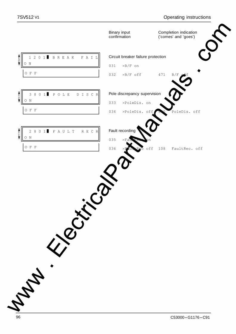
Operating instructions7SV512 V1
C53000---G1176---C9196
Binary input Completion indicationconfirmation (’comes’ and ’goes’)
1 2 0 1 B R E A K F A I L
O N
O F F
Circuit breaker failure protection
031 >B/F on
032 >B/F off 471 B/F off
3 8 0 1 P O L E D I S C R
O N
O F F
Pole discrepancy supervision
033 >PoleDis. on
034 >PoleDis. off 600 PoleDis. off
2 8 0 1 F A U L T R E C R
O N
O F F
Fault recording
035 >FaultRec on
036 >FaultRec off 108 FaultRec. off
www . El
ectric
alPar
tMan
uals
. com
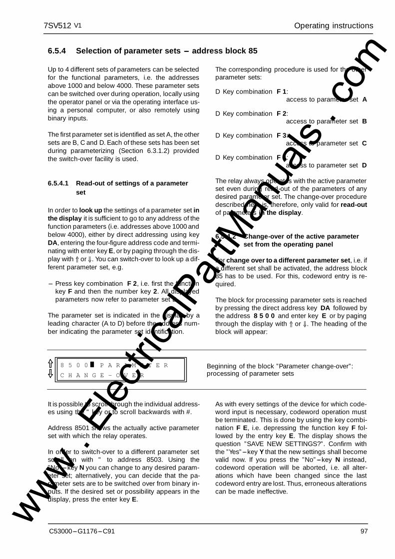
Operating instructions7SV512 V1
97C53000---G1176---C91
6.5.4 Selection of parameter sets --- address block 85
Up to 4 different sets of parameters can be selectedfor the functional parameters, i.e. the addressesabove 1000 and below 4000. These parameter setscan be switched over during operation, locally usingthe operator panel or via the operating interface us-ing a personal computer, or also remotely usingbinary inputs.
The first parameter set is identified as set A, the othersets are B, C and D. Each of these sets has been setduring parameterizing (Section 6.3.1.2) providedthe switch-over facility is used.
6.5.4.1 Read-out of settings of a parameterset
In order to look up the settings of a parameter set inthe display it is sufficient to go to any address of thefunction parameters (i.e. addresses above 1000 andbelow 4000), either by direct addressing using keyDA, entering the four-figure address code and termi-nating with enter key E, or by paging through the dis-play with ⇑ or ⇓. You can switch-over to look up a dif-ferent parameter set, e.g.
--- Press key combination F 2, i.e. first the functionkey F and then the number key 2. All displayedparameters now refer to parameter set B.
The parameter set is indicated in the display by aleading character (A to D) before the address num-ber indicating the parameter set identification.
The corresponding procedure is used for the otherparameter sets:
D Key combination F 1:access to parameter set A
D Key combination F 2:access to parameter set B
D Key combination F 3:access to parameter set C
D Key combination F 4:access to parameter set D
The relay always operates with the active parameterset even during read-out of the parameters of anydesired parameter set. The change-over proceduredescribed here is, therefore, only valid for read-outof parameters in the display.
6.5.4.2 Change-over of the active parameterset from the operating panel
For change over to a different parameter set, i.e. ifa different set shall be activated, the address block85 has to be used. For this, codeword entry is re-quired.
The block for processing parameter sets is reachedby pressing the direct address key DA followed bythe address 8 5 0 0 and enter key E or by pagingthrough the display with ⇑ or ⇓. The heading of theblock will appear:
8 5 0 0 P A R A M E T E R
C H A N G E - O V E RBeginning of the block ”Parameter change-over”:processing of parameter sets
It is possible to scroll through the individual address-es using the " key or to scroll backwards with #.
Address 8501 shows the actually active parameterset with which the relay operates.
In order to switch-over to a different parameter setscroll on with " to address 8503. Using the”No”---key N you can change to any desired param-eter set; alternatively, you can decide that the pa-rameter sets are to be switched over from binary in-puts. If the desired set or possibility appears in thedisplay, press the enter key E.
As with every settings of the device for which code-word input is necessary, codeword operation mustbe terminated. This is done by using the key combi-nation F E, i.e. depressing the function key F fol-lowed by the entry key E. The display shows thequestion ”SAVE NEW SETTINGS?”. Confirm withthe ”Yes”---key Y that the new settings shall becomevalid now. If you press the ”No”---key N instead,codeword operation will be aborted, i.e. all alter-ations which have been changed since the lastcodeword entry are lost. Thus, erroneous alterationscan be made ineffective.
www . El
ectric
alPar
tMan
uals
. com
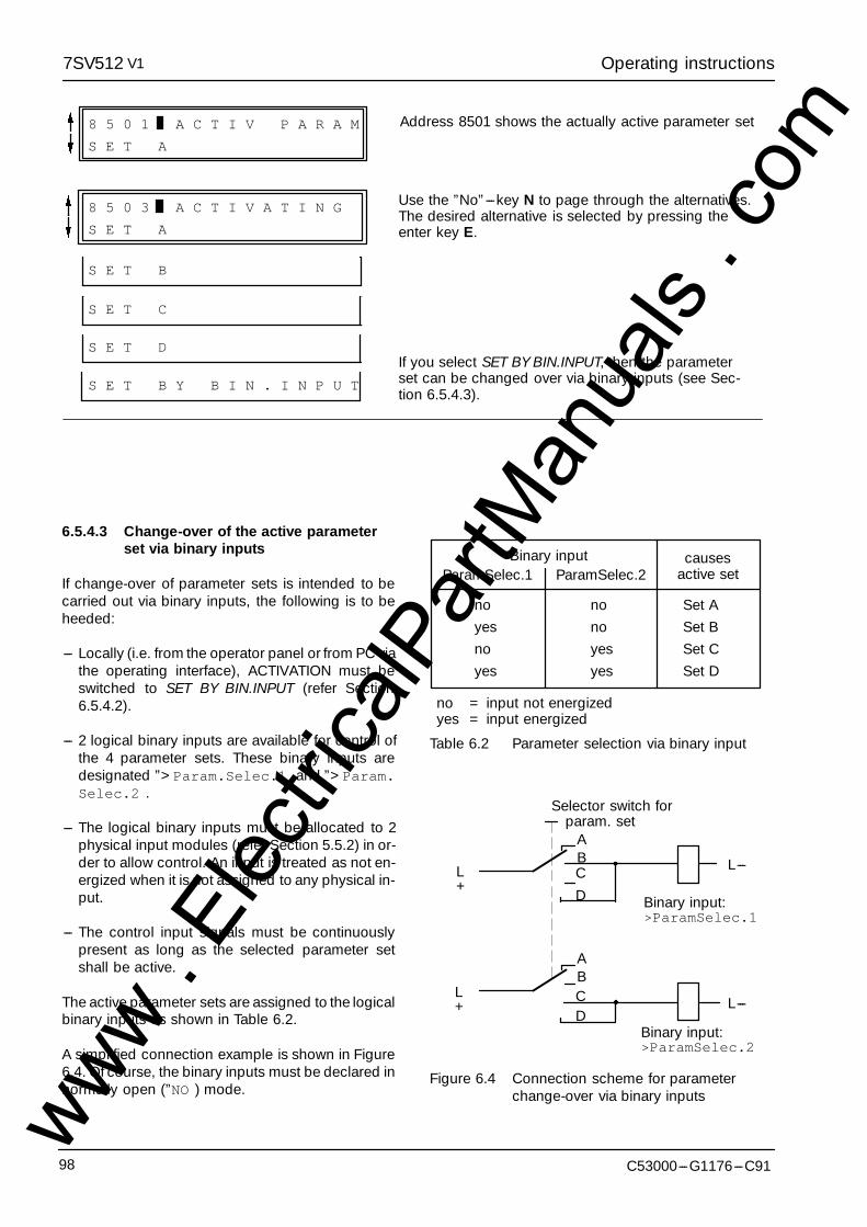
Operating instructions7SV512 V1
C53000---G1176---C9198
8 5 0 1 A C T I V P A R A M
S E T A
Address 8501 shows the actually active parameter set
S E T C
S E T D
8 5 0 3 A C T I V A T I N G
S E T A
S E T B
Use the ”No”---key N to page through the alternatives.The desired alternative is selected by pressing theenter key E.
If you select SET BY BIN.INPUT, then the parameterset can be changed over via binary inputs (see Sec-tion 6.5.4.3).
S E T B Y B I N . I N P U T
6.5.4.3 Change-over of the active parameterset via binary inputs
If change-over of parameter sets is intended to becarried out via binary inputs, the following is to beheeded:
--- Locally (i.e. from the operator panel or from PC viathe operating interface), ACTIVATION must beswitched to SET BY BIN.INPUT (refer Section6.5.4.2).
--- 2 logical binary inputs are available for control ofthe 4 parameter sets. These binary inputs aredesignated ”>Param.Selec.1 and ”>Param.Selec.2 .
--- The logical binary inputs must be allocated to 2physical input modules (refer Section 5.5.2) in or-der to allow control. An input is treated as not en-ergized when it is not assigned to any physical in-put.
--- The control input signals must be continuouslypresent as long as the selected parameter setshall be active.
The active parameter sets are assigned to the logicalbinary inputs as shown in Table 6.2.
A simplified connection example is shown in Figure6.4. Of course, the binary inputs must be declared innormally open (”NO ) mode.
noyesnoyes
Set ASet BSet CSet D
nonoyesyes
ParamSelec.2ParamSelec.1causes
active setBinary input
no = input not energizedyes = input energized
Table 6.2 Parameter selection via binary input
param. setABCD
ABCD
Binary input:>ParamSelec.1
Binary input:>ParamSelec.2
L+
L+
L---
L---
Selector switch for
Figure 6.4 Connection scheme for parameterchange-over via binary inputswww .
Elec
tricalP
artM
anua
ls . c
om
Operating instructions7SV512 V1
99C53000---G1176---C91
6.6 Testing and commissioning
6.6.1 General
Prerequisite for commissioning is the completion ofthe preparation procedures detailed in Chapter 5.
Hazardous voltages are present in thiselectrical equipment during operation.Non-observance of the safety rules can re-sult in severe personal injury or propertydamage.
Only qualified personnel shall work on andaround this equipment after becomingthoroughly familiar with all warnings andsafety notices of this manual as well as withthe applicable safety regulations.
Particular attention must be drawn to thefollowing:
" The earthing screw of the device mustbe connected solidly to the protectiveearth conductor before any other con-nection is made.
" Hazardous voltages can be present onall circuits and components con-nected to the supply voltage or to themeasuring and test quantities.
" Hazardous voltages can be present inthe device even after disconnection ofthe supply voltage (storage capaci-tors!).
" The limit values given in the Technicaldata (Section 3.1) must not be exceed-ed at all, not even during testing andcommissioning.
! Warning
When testing the unit with a secondary injection testset, it must be ensured that no other measured val-ues are connected and that the tripping leads to thecircuit breaker trip-coils have been interrupted.
Secondary connections of the currenttransformers must be short-circuitedbefore the current leads to the relay areinterrupted!If a test switch is installed which automati-cally short-circuits the current transformersecondary leads, it is sufficient to set thisswitch to the ”Test” position. The short-cir-cuit switch must be checked beforehand(refer Section 5.2.5).
DANGER!
It is recommended that the actual settings for therelay be used for the testing procedure. If these val-ues are not (yet) available, test the relay with the fac-tory settings. In the following description of the testsequence the preset settings are assumed.
For the functional tests a three-phase symmetricalcurrent source with individually adjustable currentsshould be available. For checking the pick-up valuesa single-phase current source is sufficient, but this isnot adequate for a correct functional check of themeasured value monitoring systems.
If unsymmetrical currents occur during the tests it islikely that the asymmetry monitoring will frequentlyoperate. This is of no concern because the conditionof steady-state measured values is monitored and,under normal operating conditions, these are sym-metrical; under short circuit conditions these moni-toring systems are not effective.
NOTE! The accuracy which can be achieved duringtesting depends on the accuracy of the testingequipment. The accuracy values specified in theTechnical data can only be reproduced under thereference conditions set down in IEC 60255 resp.VDE 0435/part 303 and with the use of precisionmeasuring instruments. The tests are therefore to belooked upon purely as functional tests.
During all the tests it is important to ensure that thecorrect command (trip) contacts close, that theproper indications appear at the LEDs and the out-put relays for remote signalling. If the relay is con-nected to a central memory device via the serial in-terface, correct communication between the relayand the master station must be checked.
After tests which cause LED indications to appear,these should be reset, at least once by each of thepossible methods: the reset button on the front plateand via the remote reset relay (see connection dia-grams, Appendix A). If the reset functions have beentested, resetting the stored indications is no morenecessary as they are erased automatically witheach new pick-up of the relay and replaced by thenew annunciations.www .
Elec
tricalP
artM
anua
ls . c
om
Operating instructions7SV512 V1
C53000---G1176---C91100
6.6.2 Testing the circuit breaker failure protection
In order to test the circuit breaker failure protection,this function must be switched on, i.e. address 1201BREAK FAIL = ON. The end fault protection is madeineffective by setting address 1220 to T---ENDFAULT= 1.
Before a test current is injected, the initiation condi-tions must be fulfilled: The binary input functions”>Start” (FNo 70, allocated to INPUT 10) and”>Trip” (FNo 72, allocated to INPUT 9 when deliv-ered) must be energized. Binary input function ”>B/F Block” (FNo 77, allocated to INPUT 8 when deliv-ered) must not be energized. In addition, input func-tion ”>Trip 3pole” (FNo 73) is energized.
Testing can be performed with single-phase, two-phase or three-phase test current. When testingsingle-phase, the test current is injected via onephase and earth.
Caution!!Test currents larger than 4 times IN mayoverload and damage the relay if appliedcontinuously (refer to Section 3.1.1 foroverload capability). Observe a coolingdown period!
For current above 4 ¡ IN, therefore, measurementshall be performed dynamically. It should be statedthat the relay picks up at 1.1 times setting value anddoes not pick up at 0.9 times setting value. Currentbelow 4 ¡ IN can be slowly increased.
When the set value for I---BF (address 1202, factorysetting 0.1 x IN) is exceeded the indication ”BFPStart (FNo 473, on LED 1 when delivered) ap-pears. The further reaction of the breaker failure pro-tection depends on the parameterized functions.
With two-stage breaker failure protection (address1203 is set TRIP CRoff = NO), the annunciation ”BFPCrossTrip (FNo 506, LED 2 when delivered) ap-pears after expiry of the time delay T1---3POLE (ad-dress 1206, 0.00 s when delivered). Check that theassigned trip relay contacts close (trip relays 3 to 5when delivered).
After expiry of the time T2---CURRENT (address1212, factory setting 0.15 s) the annunciation ”BFPTrip BB appears (FNo 507, LED 3 when deliv-ered). Check that the assigned trip relay contactsclose (trip relays 1 when delivered). Additionally, theintertrip signal ”BFP TransTrip appears (FNo
508, LED 4 when delivered). Check that the as-signed trip relay contacts close (trip relays 2 whendelivered).
When the delay time T---1---3POLE (address 1206) isnot set to 0.00 s (as delivered), then it must benoted, that the total delay time until bus-bar trip sig-nal ”BFP Trip BB may be composed of the sumof T1---3POLE and T2---CURRENT (if address 1211is set T---TRIP---BB = T1 + T2; as delivered), or it isonly the time T2---CURRENT (if address 1211 is setT---TRIP---BB = T2).
With single-stage breaker failure protection (ad-dress 1203 is set TRIP CRoff = YES), address 1211T---TRIP---BB should be set to T2, otherwise address1206 must be set T1---3POLE must be set to 0.00 s inorder to ensure that this time will not be added to theexpected tripping time. After expiry of T2---CUR-RENT (address 1212, 0.15 s at delivery) the annun-ciation ”BFP Trip BB appears (FNo 507, LED 3when delivered). Check that the assigned trip relaycontacts close (trip relays 1 when delivered). Addi-tionally, the intertrip signal ”BFP TransTrip ap-pears (FNo 508, LED 4 when delivered). Check thatthe assigned trip relay contacts close (trip relays 2when delivered). Switch off the test current.
It must generally be noted that the set times are puredelay times; operating times of the measurementfunctions are not included.
The tests carried out until now have used the currentflow as breaker failure criterion. The following testswith the breaker auxiliary contact criterion are car-ried out without test current. The binary inputs asabove remain energized.
In addition, one of the binary input functions for thebreaker auxiliary contacts is energized (FNo 16 toFNo 20), which is allocated to a binary input (e.g. IN-PUT 6 for the conditions as delivered), preferablyone that is actually used. Tests can be performedwith single-stage and/or two-stage breaker failureprotection, as it is done with the current tests. Butnote that the time delay for the second stage is nowT2---CB---AUX (address 1213).
When the reset time of the protection is measured itmust be considered that the values given in theTechnical data are valid only when the test current isinterrupted at the moment of its zero crossing.
Finally, de-energize all binary inputs.
www . El
ectric
alPar
tMan
uals
. com

Operating instructions7SV512 V1
101C53000---G1176---C91
6.6.3 Testing the end fault protection
The end fault protection is made effective. Toachieve this, the time T---ENDFAULT (address 1220)must be set back to a definite value (not 1), e.g. tothe default value 0.10 s.
One of the binary input functions for the breaker aux-iliary contacts is energized (FNo 16 to FNo 20),which is allocated to a binary input (e.g. INPUT 6 forthe conditions as delivered), preferably one that isactually used.
In addition, the binary input function ”>Start” (FNo70, INPUT 10) is energized.
Testing can be performed with single-phase, two-phase or three-phase test current above the pick-upvalue of the breaker failure protection (address1202, 0.1 ¡ IN when delivered). When testing single-phase, the test current is injected via one phase andearth.
Caution!!Test currents larger than 4 times IN mayoverload and damage the relay if appliedcontinuously (refer to Section 3.1.1 foroverload capability). Observe a coolingdown period!
After expiry of the time T---ENDFAULT (address1220, factory setting 0.10 s) the annunciation ”BFPTendFault appears (FNo 514, not marshalledwhen delivered). Check that the trip relay assignedto the function ”BFP TransTrip (FNo 508, triprelay 2 when delivered) closes its contacts.
It must be noted that the set times are pure delaytimes; operating times of the measurement func-tions are not included.
Switch off test current, de-energize all binary inputs.
6.6.4 Testing the circuit breaker polediscrepancy supervision
For these tests the pole discrepancy supervisionmust be configured as POLE DISCR = EXIST (ad-dress 7838) during configuration (refer to Section4.5.2) and switched on (address 3801 POLE---DISC= ON).
One of the binary input functions for the breaker aux-iliary contacts is energized (FNo 16, FNo 17, FNo 18,or FNo20), which is allocated to a binary input (e.g.INPUT 6 for the conditions as delivered), preferablyone that is actually used. The binary inputs assignedto FNo 19 ”>CB Aux. 3p C and FNo 70”>Start must not be energized!
Testing can be performed with single-phase, two-phase or three-phase test current above the pick-upvalue of the breaker failure protection (address1202, 0.1 ¡ IN when delivered). When testing single-phase, the test current is injected via one phase andearth.
Caution!!Test currents larger than 4 times IN mayoverload and damage the relay if appliedcontinuously (refer to Section 3.1.1 foroverload capability). Observe a coolingdown period!
After expiry of the time T---DISCREP (address 3802,factory setting 2 s) three-pole trip command is givenby the pole discrepancy supervision. Check that thetrip relays assigned to the local trip ”Pole-Dis.Trip (FNo 610, trip relays 3 to 5 when deliv-ered) close their contacts.
It must be noted that the set times are pure delaytimes; operating times of the measurement func-tions are not included.
Switch off test current, de-energize all binary inputs.
www . El
ectric
alPar
tMan
uals
. com

Operating instructions7SV512 V1
C53000---G1176---C91102
6.7 Commissioning using primary tests
All secondary testing sets and equipment must beremoved. Reconnect current and voltage transform-ers. For testing with primary values the line must beenergized.
Primary tests shall be performed only bqualified personnel which is trainedcommissioning of protection systems anfamiliar with the operation of the protecteobject as well as the rules and regulation(switching, earthing, etc.)
! Warning
Because of the variety of application possibilitiesand possible switch-gear configuration, a detaileddescription of the applicable tests is not possible.The most important thing is that the local circum-stances and the switch-gear and protection dia-grams are observed.
It is recommended that the local circuit breaker ofthe feeder under test is isolated at both sides, i.e. thebus-bar disconnector(s) and the line disconnectormust be opened. Thus, switching of the circuitbreaker is possible without danger.
Caution!!The protection relay will issue bus-bar tripcommand even during tests on the localfeeder breaker. The trip signal to the adja-cent circuit breakers of the bus-bar shouldbe made ineffective, e.g. by switching off ofthe corresponding control voltages.
The trip command of the feeder protection to the lo-cal feeder circuit breaker is also interrupted until finalcompletion of the tests in order to ensure that onlythe breaker failure protection can trip this breaker.
The following lists do not claim to cover all possibili-ties. On the other hand, they may contain items thatcan be bypassed in the actual application.
6.7.1 Checking the initiation condi-tions
All possible initiation conditions must be checked.The following hints presuppose that at least thebinary inputs INPUT 8, INPUT 9, and INPUT 10 areallocated to the input functions as delivered, so thatthey are included in the trip release monitoring of thedevice.
The annunciation ”BFP-Pickup” (FNo 472) mustappear each time the beaker failure protection is ini-tiated. When the relay is delivered, this annunciationis not allocated to any output relay or LED, but it ap-pears ”Coming” and ”Going” in the operational an-nunciations (address 5100, refer to Section 6.4.2).
At first, ensure that the feeder circuit breaker is open.
a) Initiation by single-pole trip command L1 of thefeeder protection:Binary input functions ”>Trip L1”, ”>Trip”,”>Start”, and ”>Start N” (if used) are trig-gered.
b) Initiation by single-pole trip command L2 of thefeeder protection:Binary input functions ”>Trip L2”, ”>Trip”,”>Start”, and ”>Start N” (if used) are trig-gered.
c) Initiation by single-pole trip command L3 of thefeeder protection:Binary input functions ”>Trip L3”, ”>Trip”,”>Start”, and ”>Start N” (if used) are trig-gered.
d) Initiation by three-pole trip command of the feederprotection:Binary input functions ”>Trip L1”, ”>TripL2”, ”>Trip L3”, ”>Trip”, and”>Start”, are triggered.
e)Initiation by three-pole trip command of a three-pole feeder protection (e.g. overvoltage protec-tion):Binary input functions ”>Trip 3 pole”,”>Trip”, and ”>Start”, are triggered.
De-energize all binary inputs.
www . El
ectric
alPar
tMan
uals
. com

Operating instructions7SV512 V1
103C53000---G1176---C91
6.7.2 Checking the local trip withbreaker failure criterion from theauxiliary contacts
The circuit breaker --- isolated by its adjacent dis-connectors, as mentioned above --- is now switchedon. Note that the pole discrepancy protection of thecircuit breaker may initiate a later three-pole trip dur-ing these tests. The internal pole discrepancy super-vision may operate, too. The circuit breaker isswitched on before each test.
a) Initiation by single-pole trip command L1 of thefeeder protection:Single-pole trip command is issued by the break-er failure protection after T1---1POLE (address1205), provided local trip (cross trip) is allowed(according address 1203) and single-pole trip isparameterized (address 1204).
b) Initiation by single-pole trip command L2 of thefeeder protection:Single-pole trip command is issued by the break-er failure protection after T1---POLE (address1205), provided local trip (cross trip) is allowed(according address 1203) and single-pole trip isparameterized (address 1204).
c) Initiation by single-pole trip command L3 of thefeeder protection:Single-pole trip command is issued by the break-er failure protection after T1---1POLE (address1205), provided local trip (cross trip) is allowed(according address 1203) and single-pole trip isparameterized (address 1204).
d) Initiation by three-pole trip command of the feederprotection:Three-pole trip command is issued by the breakerfailure protection after T1---3POLE (address1206), provided local trip (cross trip) is allowed(according address 1203).
De-energize all binary inputs.
6.7.3 Checking the local trip and thecurrent circuits
The current transformer connections are checkedwith real primary current. Before the protected ob-ject is energized, it must be ensured, that a back-upprotection is effective in case a real fault should oc-cur during the tests.
A load current of at least 10 % of the rated current isnecessary. If the measuring circuit connections arecorrect, none of the measured value monitoring sys-tems in the relay will operate. If a fault indication ap-pears, the possible causes can be found in the op-erational annunciations (Address 5100).
For current sum errors, the matching factors (Sec-tion 6.3.3) should be checked.
If the symmetry monitoring appears, it is possiblethat asymmetry is in fact present on the line. If this isa normal operational condition, the correspondingmonitoring function should be set at a less sensitivevalue (Section 6.3.6).
Currents can be read off on the display in the front orvia the operating interface in block 57 and comparedwith the actual measured values. If substantial devi-ations occur or if the unit indicates a considerableearth current, then the current transformer connec-tions are incorrect. Short-circuit the current trans-formers and make corrections.
The circuit breaker is closed again for the followingtrip tests. Note that the integrated pole discrepancysupervision may operate and initiate three-pole trip-ping. As the correct allocation of the individual circuitbreaker poles is already verified during the tests ac-cording to Section 6.7.2, one single test is sufficient,here.
a) Initiation by three-pole trip command of the feederprotection:Three-pole trip command is issued by the breakerfailure protection after T1---3POLE (address 1206)provided local trip (cross trip) is allowed (accord-ing address 1203).
Finally, de-energize all binary inputs. Open circuitbreaker
www . El
ectric
alPar
tMan
uals
. com

Operating instructions7SV512 V1
C53000---G1176---C91104
6.7.4 Checking the intertrip to the op-posite feeder end
All devices which are necessary for transmission ofthe intertrip signal to the opposite feeder end mustbe commissioned in accordance with the asso-ciated commissioning instructions. The transmis-sion link must be checked.
The trip commands to the bus-bar circuit breakersremain ineffective during the test. The disconnec-tors at both sides of the feeder circuit breaker mustbe open. The circuit breaker is closed.
At the remote end of the feeder, the circuit breakermust be isolated from the feeder and the bus-bar,too. The circuit breaker is closed there.
Anyone of the tests as described in Section 6.7.2 isrepeated. The initiation conditions remain effectiveafter the local feeder breaker has tripped.
After expiry of the time T2---CB---AUX (address 1213)the intertrip signal is transmitted and the circuitbreaker of the opposite feeder end is tripped. It ispossible that trip of the remote end breaker is madedependent of further conditions: this must be con-sidered. When assessing the time delay it must betaken into account that this delay depends on theparameter T---TRIP---BB (address 1211): it may bestarted either with initiation or after the local trip com-mand of the breaker failure protection.
If the intertrip check is to be carried out with currentflow as breaker failure criterion (e.g. because theauxiliary contact criterion is not used), then eitherthe feeder must be energized at both ends in orderto produce a current above the pick-up value I---BF(address 1202), or a corresponding secondary cur-rent must be injected into the relay under test. In thefirst case, it must be ensured that a back-up protec-tion for the feeder is effective in case a real faultwould occur during the test.
6.7.5 Checking the bus-bar trip
The distribution of the trip commands to the adja-cent circuit breakers of the bus-bar depends widelyon the bus-bar arrangement.
Checking the bus-bar trip should be carried out aftercompletion of the tests on all individual feeder circuitbreakers.
In most cases a trip bus is installed for the trip com-mands of the bus-bar breakers. This trip bus is ener-gized by the trip relay 1 of each breaker failure pro-tection relay (command function ”BFP Trip BB”,FNo 507), if applicable, dependent of the position ofthe bus-bar disconnector(s) of the feeder under test.
The important thing is that the bus-bar trip com-mand arrives at all circuit breakers associated withthat bus-bar section, to which the feeder of the origi-nating protection relay is connected, including anybus tie, and that the bus-bar trip command does notarrive at any of the other circuit breakers. The bus-bar trip checks must be performed such, that finallyall switching combinations have been covered.
After completion of the tests, it must be carefullychecked that the required operational status of thetrip bus(ses) is re-arranged (e.g. in case that certaincircuits have been interrupted for certain tests) andthat all control voltages are switched on (in case cer-tain control voltages have been switched off for cer-tain tests). This is also valid for all the tripping com-mands of feeder protection relays which have beeninterrupted in order to simulate a breaker failure con-dition.
www . El
ectric
alPar
tMan
uals
. com
Operating instructions7SV512 V1
105C53000---G1176---C91
6.8 Putting the relay into operation
All setting values should be checked again, in casethey were altered during the tests. Particularly checkthat all desired protection and ancillary functionshave been programmed in the configuration param-eters (address block 78, refer to Section 5.4) and alldesired protection functions have been switchedON.
The counters for circuit breaker operation statisticsshould be erased (address block 82, refer to Section6.5.2).
Push the key M/S on the front. The display showsthe beginning of the annunciation blocks. Thus, it ispossible that the measured values for the quiescentstate of the relay can be displayed (see below).These values has been chosen during configuration(refer to Section 5.3.2) under the addresses 7005and 7006.
Stored indications on the front plate should be resetby pressing the push-button ”RESET LED” on thefront so that from then on only real faults are indi-cated. From that moment the measured values ofthe quiescent state are displayed. During pushingthe RESET button, the LEDs on the front will light up(except the ”Blocked”---LED); thus, a LED test is per-formed at the same time.
Check that the module is properly inserted. Thegreen LED must be on on the front; the red LED mustnot be on.
Close housing cover.
All terminal screws --- even those not in use --- mustbe tightened.
If a test switch is available, then this must be in theoperating position.
The protection relay is now ready for operation.
www . El
ectric
alPar
tMan
uals
. com

Maintenance and fault tracing7SV512 V1
106 C53000---G1176---C91
7 Maintenance and fault tracing
Siemens digital protection relays are designed to re-quire no special maintenance. All measurement andsignal processing circuits are fully solid state andtherefore completely maintenance free. Input mod-ules are even static, relays are hermetically sealed orprovided with protective covers.
If the device is equipped with a back-up battery forsaving of stored annunciations and the internal timeclock, the clock module should be replaced after atleast 10 years of operation. (refer to Section 7.2).This recommendation is valid independent onwhether the battery has been discharged by occa-sional supply voltage failures or not.
As the protection is almost completely self-moni-tored, from the measuring inputs to the commandoutput relays, hardware and software faults are au-tomatically annunciated. This ensures the high avail-ability of the relay and allows a more corrective rath-er than preventive maintenance strategy. Tests atshort intervals become, therefore, superfluous.
With detected hardware faults the relay blocks itself;drop-off of the availability relay signals ”equipmentfault”. If there is a fault detected in the external mea-suring circuits, generally an alarm is given only.
Recognized software faults cause the processor toreset and restart. If such a fault is not eliminated byrestarting, further restarts are initiated. If the fault isstill present after three restart attempts the protec-tive system will switch itself out of service and indi-cate this condition by the red LED ”Blocked” on thefront plate. Drop-off of the availability relay signals”equipment fault”.
The reaction to defects and indications given by therelay can be individually and in chronological se-quence read off as operational annunciations underthe address 5100, for defect diagnosis (refer to Sec-tion 6.4.2).
If the relay is connected to a local substation auto-mation system (LSA), defect indications will also betransferred via the serial interface to the central con-trol system.
Ensure that the connection modules are notdamaged when removing or inserting thedevice modules! Hazardous voltages mayoccur when the heavy current plugs aredamaged!
! Warning
7.1 Routine checks
Routine checks of characteristics or pick-up valuesare not necessary as they form part of the continu-ously supervised firmware programs. The plannedmaintenance intervals for checking and mainte-nance of the plant can be used to perform operation-al testing of the protection equipment. This mainte-nance serves mainly for checking the interfaces ofthe unit, i.e. the coupling with the plant. The follow-ing procedure is recommended:
--- Read-out of operational values (address block57) and comparison with the actual values forchecking the analog interfaces.
--- Simulation of an internal short-circuit with 4 x IN forchecking the analog input at high currents.
Hazardous voltages can be present onall circuits and components connectedwith the supply voltage or with the meas-uring and test quantities!
! Warning
Test currents larger than 4 times IN mayoverload and damage the relay if appliedcontinuously (refer to Section 3.1.1 foroverload capability). Observe a coolingdown period!
! Caution!
www . El
ectric
alPar
tMan
uals
. com
Maintenance and fault tracing7SV512 V1
107C53000---G1176---C91
7.2 Replacing the clock module
If the device is equipped with the clock option (mod-el 7SV512K---KKKK1 ---KK, refer Section 2.3 Orderingdata), the device annunciations are stored in NV---RAMs. The clock module contains also the back-upbattery so that the annunciations are retained evenwith a longer failure of the d.c. supply voltage.
The clock module should be replaced at the latestafter 10 years of operation.
Recommended clock module:
--- DALLASDS 1386 --- 32 KRAMified TIMEKEEPER
The module is located on the CPU cart. The com-plete draw-out module must be removed from thehousing in order to replace the clock module.
The procedure when replacing the clock module isdescribed below.
--- Prepare area of work: provide conductive surfacefor the basic module.
--- Open housing cover.
--- Read out device annunciations, i.e. all addresseswhich commence with 5 (5000 onwards). This iscarried out most convenient using the front oper-ating interface and a personal computer with theDIGSIr protection data processing program; theinformation is thus stored in the PC.
Note: All configuration data and settings of the de-vice are stored in EEPROMs protected againstswitching off of the power supply. They are storedindependent of the back-up battery. They are,therefore, neither lost when the battery is re-placed nor when the device is operated without abattery.
--- Prepare the battery as in Figure 7.1:
Hazardous voltages can be present inthe device even after disconnection ofthe supply voltage or after removal of themodules from the housing (storage ca-pacitors)!
! Warning
--- Loosen the draw-out module using the pullingaids provided at the top and bottom. (Figure 7.3).
Electrostatic discharges via the compo-nent connections, the PCB tracks or theconnecting pins of the modules must beavoided under all circumstances by pre-viously touching an earthed metal sur-face.
! Caution!
--- Pull out the module and place onto the conductivesurface.
--- Get access to the CPU board.
--- Pull out used clock module from the socket ac-cording to Figure 7.1; do not place on the con-ductive surface!
--- Insert the prepared new clock module into thesocket; observe correct mounting position.
--- Remount PCB board to the draw-out module.
--- Insert draw-out module into the housing; ensurethat the releasing lever is pushed fully to the rightbefore the module is pressed in.
--- Firmly push in the module using the releasing le-ver. (Figure 7.3).
The discharged battery contains Lithium.It must only be disposed off in line with theapplicable regulations!
Do not reverse polarities! Do not re-charge! Do not throw into fire! Dangerof explosion!
! Warning
--- Provided the internal system clock is not automat-ically synchronized via the LSA interface, it cannow be set or synchronized as described in Sec-tion 6.5.1
--- Close housing cover.
The replacement of the clock module has thus beencompleted.
www . El
ectric
alPar
tMan
uals
. com
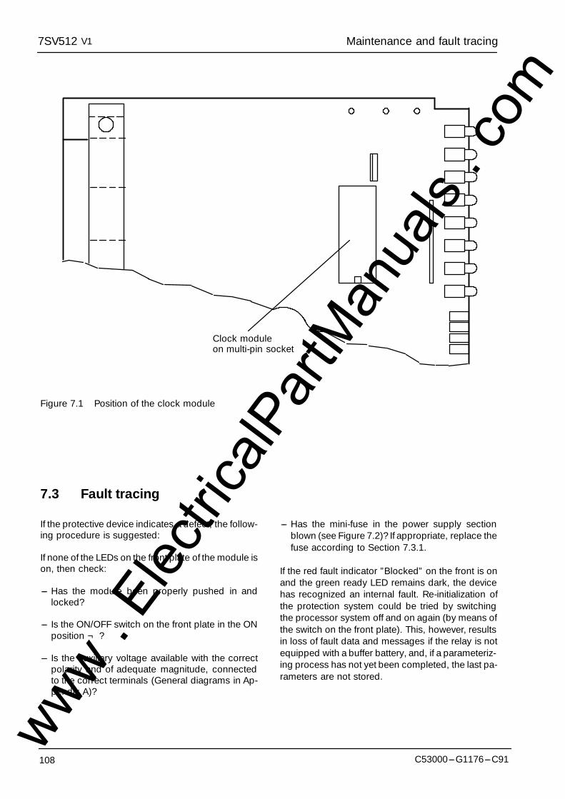
Maintenance and fault tracing7SV512 V1
108 C53000---G1176---C91
Clock moduleon multi-pin socket
Figure 7.1 Position of the clock module
7.3 Fault tracing
If the protective device indicates a defect, the follow-ing procedure is suggested:
If none of the LEDs on the front plate of the module ison, then check:
--- Has the module been properly pushed in andlocked?
--- Is the ON/OFF switch on the front plate in the ONposition ¬ ?
--- Is the auxiliary voltage available with the correctpolarity and of adequate magnitude, connectedto the correct terminals (General diagrams in Ap-pendix A)?
--- Has the mini-fuse in the power supply sectionblown (see Figure 7.2)? If appropriate, replace thefuse according to Section 7.3.1.
If the red fault indicator ”Blocked” on the front is onand the green ready LED remains dark, the devicehas recognized an internal fault. Re-initialization ofthe protection system could be tried by switchingthe processor system off and on again (by means ofthe switch on the front plate). This, however, resultsin loss of fault data and messages if the relay is notequipped with a buffer battery, and, if a parameteriz-ing process has not yet been completed, the last pa-rameters are not stored.
www . El
ectric
alPar
tMan
uals
. com
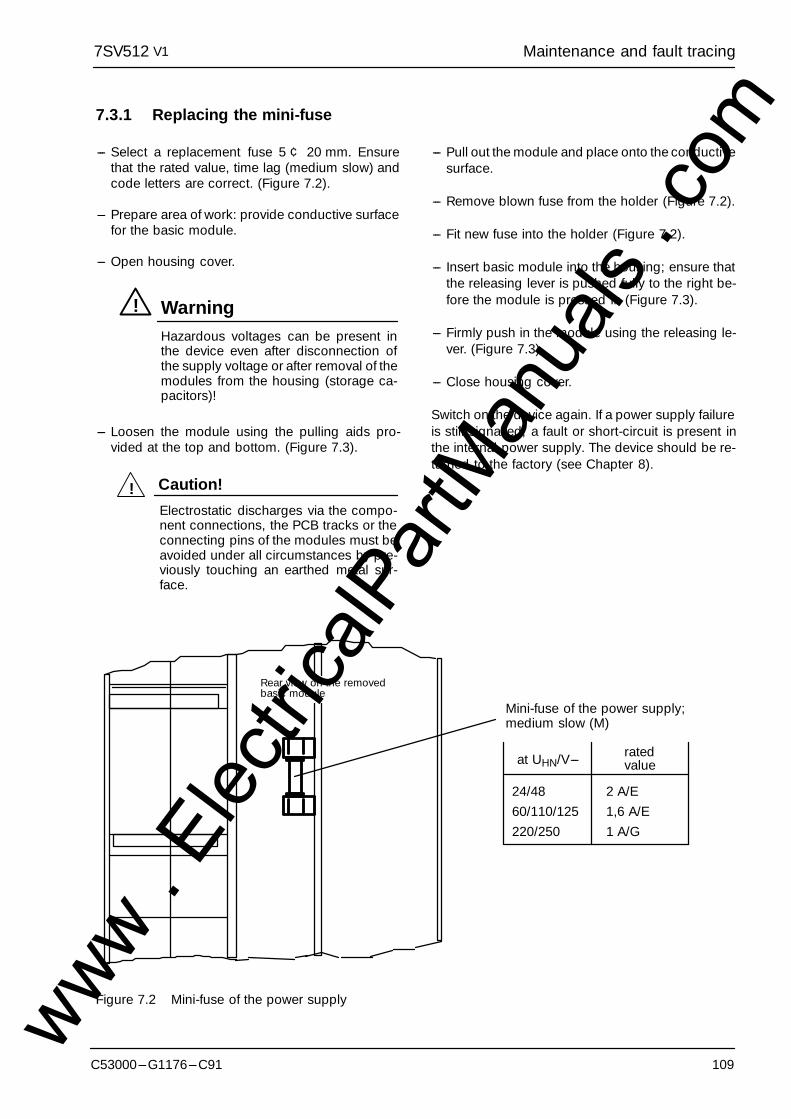
Maintenance and fault tracing7SV512 V1
109C53000---G1176---C91
7.3.1 Replacing the mini-fuse
--- Select a replacement fuse 5 ¢ 20 mm. Ensurethat the rated value, time lag (medium slow) andcode letters are correct. (Figure 7.2).
--- Prepare area of work: provide conductive surfacefor the basic module.
--- Open housing cover.
Hazardous voltages can be present inthe device even after disconnection ofthe supply voltage or after removal of themodules from the housing (storage ca-pacitors)!
! Warning
--- Loosen the module using the pulling aids pro-vided at the top and bottom. (Figure 7.3).
Electrostatic discharges via the compo-nent connections, the PCB tracks or theconnecting pins of the modules must beavoided under all circumstances by pre-viously touching an earthed metal sur-face.
! Caution!
--- Pull out the module and place onto the conductivesurface.
--- Remove blown fuse from the holder (Figure 7.2).
--- Fit new fuse into the holder (Figure 7.2).
--- Insert basic module into the housing; ensure thatthe releasing lever is pushed fully to the right be-fore the module is pressed in (Figure 7.3).
--- Firmly push in the module using the releasing le-ver. (Figure 7.3).
--- Close housing cover.
Switch on the device again. If a power supply failureis still signalled, a fault or short-circuit is present inthe internal power supply. The device should be re-turned to the factory (see Chapter 8).
24/48 2 A/E60/110/125 1,6 A/E220/250 1 A/G
Rear view on the removedbasic module
Mini-fuse of the power supply;medium slow (M)
ratedvalueat UHN/V---
Figure 7.2 Mini-fuse of the power supplywww . El
ectric
alPar
tMan
uals
. com
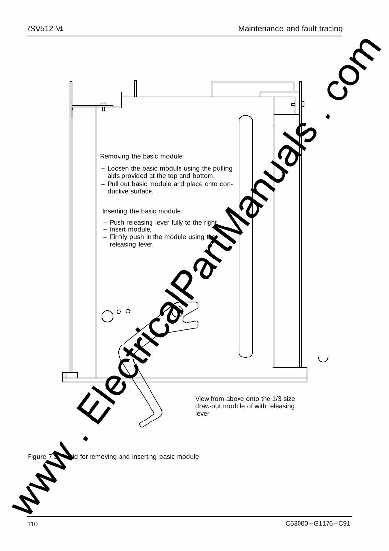
Maintenance and fault tracing7SV512 V1
110 C53000---G1176---C91
Removing the basic module:
--- Loosen the basic module using the pullingaids provided at the top and bottom,
--- Push releasing lever fully to the right,--- Insert module,--- Firmly push in the module using the
releasing lever.
Inserting the basic module:
--- Pull out basic module and place onto con-ductive surface.
View from above onto the 1/3 sizedraw-out module of with releasinglever
Figure 7.3 Aid for removing and inserting basic module
www . El
ectric
alPar
tMan
uals
. com
Repairs, Storage7SV512 V1
111C53000---G1176---C91
8 Repairs
Repair of defective modules is not recommended atall because specially selected electronic compo-nents are used which must be handled in accor-dance with the procedures required for Electrostati-cally Endangered Components (EEC). Further-more, special manufacturing techniques are neces-sary for any work on the printed circuit boards in or-der to do not damage the bath-soldered multilayerboards, the sensitive components and the protec-tive finish.
Therefore, if a defect cannot be corrected by opera-tor procedures such as described in Chapter 7, it isrecommended that the complete relay should be re-turned to the manufacturer. Use the original packag-ing for return. If alternative packing is used, this mustprovide the degree of protection against mechanicalshock, as laid down in IEC 60255---21---1 class 2 andIEC 60255---21---2 class 1.
If it is unavoidable to replace individual modules, it isimperative that the standards related to the handlingof Electrostatically Endangered Components areobserved.
Hazardous voltages can be present in thedevice even after disconnection of the sup-ply voltage or after removal of the modulefrom the housing (storage capacitors)!
! Warning
Electrostatic discharges via the componentconnections, the PCB tracks or the con-necting pins of the modules must beavoided under all circumstances by pre-viously touching an earthed metal surface.This applies equally for the replacement ofremovable components, such as EPROMor EEPROM chips. For transport and re-turning of individual modules electrostaticprotective packing material must be used.
! Caution!
Components and modules are not endangered aslong as they are installed within the relay.
Should it become necessary to exchange any de-vice or module, the complete parameter assignmentshould be repeated. Respective notes are containedin Chapter 5 and 6.
9 Storage
Solid state protective relays shall be stored in dryand clean rooms. The limit temperature range forstorage of the relays or associated spare parts is---25 _C to +55 _C (refer Section 3.1.4 under theTechnical data), corresponding to ---12 _F to 130 _F.
The relative humidity must be within limits such thatneither condensation nor ice forms.
It is recommended to reduce the storage tempera-ture to the range +10 �C to +35 �C (50 �F to 95 �F);this prevents from early ageing of the electrolytic ca-pacitors which are contained in the power supply.
For very long storage periods, it is recommendedthat the relay should be connected to the auxiliaryvoltage source for one or two days every other year,in order to regenerate the electrolytic capacitors.The same is valid before the relay is finally installed.In extreme climatic conditions (tropics) pre-warmingwould thus be achieved and condensation avoided.
Before initial energization with supply voltage, therelay shall be situated in the operating area for atleast two hours in order to ensure temperatureequalization and to avoid humidity influences andcondensation.
www . El
ectric
alPar
tMan
uals
. com

Appendix7SV512 V1
112 C53000---G1176---C91
Appendix
A General diagrams
B Connection diagrams
C Tables
www . El
ectric
alPar
tMan
uals
. com
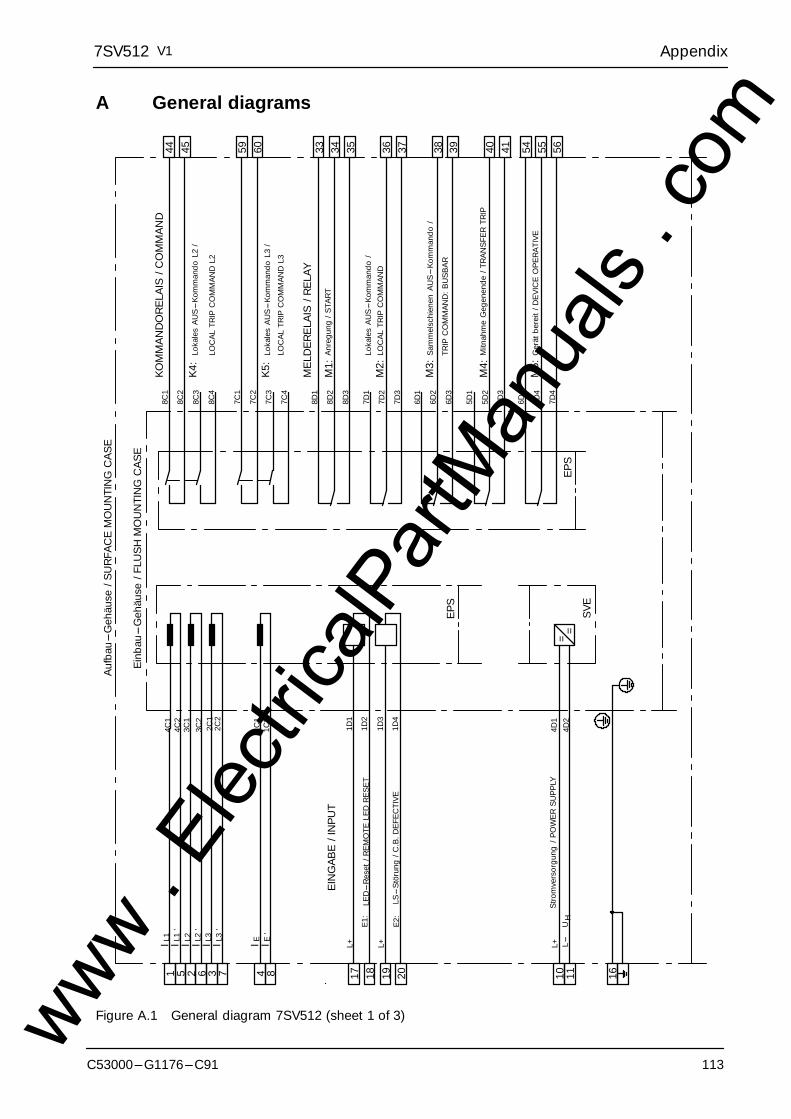
Appendix7SV512 V1
C53000---G1176---C91 113
A General diagrams
1 5I
4C1
4C2
L1’
2 6I
3C1
3C2
L2’
3 7I
2C1
2C2
L3’
1D1
1D2
17 18
L+
E1:
LED
---R
eset
/RE
MO
TELE
DR
ES
ET
1D3
1D4
19 20
L+
E2:
LS---
Stö
rung
/C.B
.DE
FEC
TIVE
EPS
44 458C
2
8C1
K4:
8C4
8C3
59 607C
2
7C1
K5:
7C4
7C3
33 348D
2
8D1
35
M1:
8D3
367D
2
7D1
37
M2:
7D3
386D
2
6D1
39
M3:
6D3
405D
2
5D1
41
M4:
5D3
EPS
Ein
bau
---G
ehäu
se/F
LUS
HM
OU
NTI
NG
CA
SE
Auf
bau
---G
ehäu
se/S
UR
FAC
EM
OU
NTI
NG
CA
SE
KOM
MA
ND
OR
ELA
IS/C
OM
MA
ND
ME
LDE
RE
LAIS
/RE
LAY
EIN
GA
BE
/IN
PUT
54 558D
4
6D4
56
M5:
7D4
Anr
egun
g/S
TAR
T
Ger
ätbe
reit
/DE
VIC
EO
PE
RA
TIVE
4 8I
1C1
1C2
E’
4D1
4D2
=10 11
L+U
=H
Stro
mve
rsor
gung
/PO
WE
RS
UP
PLY
L---
SVE
16
I L1
I L2
I L3
I E
Loka
les
AU
S---
Kom
man
doL2
/
Loka
les
AU
S---
Kom
man
doL3
/
Mitn
ahm
eG
egen
ende
/TR
AN
SFE
RTR
IP
Sam
mel
schi
enen
AU
S---
Kom
man
do/
TRIP
CO
MM
AN
D:
BU
SB
AR
LOC
AL
TRIP
CO
MM
AN
DL2
LOC
AL
TRIP
CO
MM
AN
DL3
Loka
les
AU
S---
Kom
man
do/
LOC
AL
TRIP
CO
MM
AN
D
Figure A.1 General diagram 7SV512 (sheet 1 of 3)www . El
ectric
alPar
tMan
uals
. com
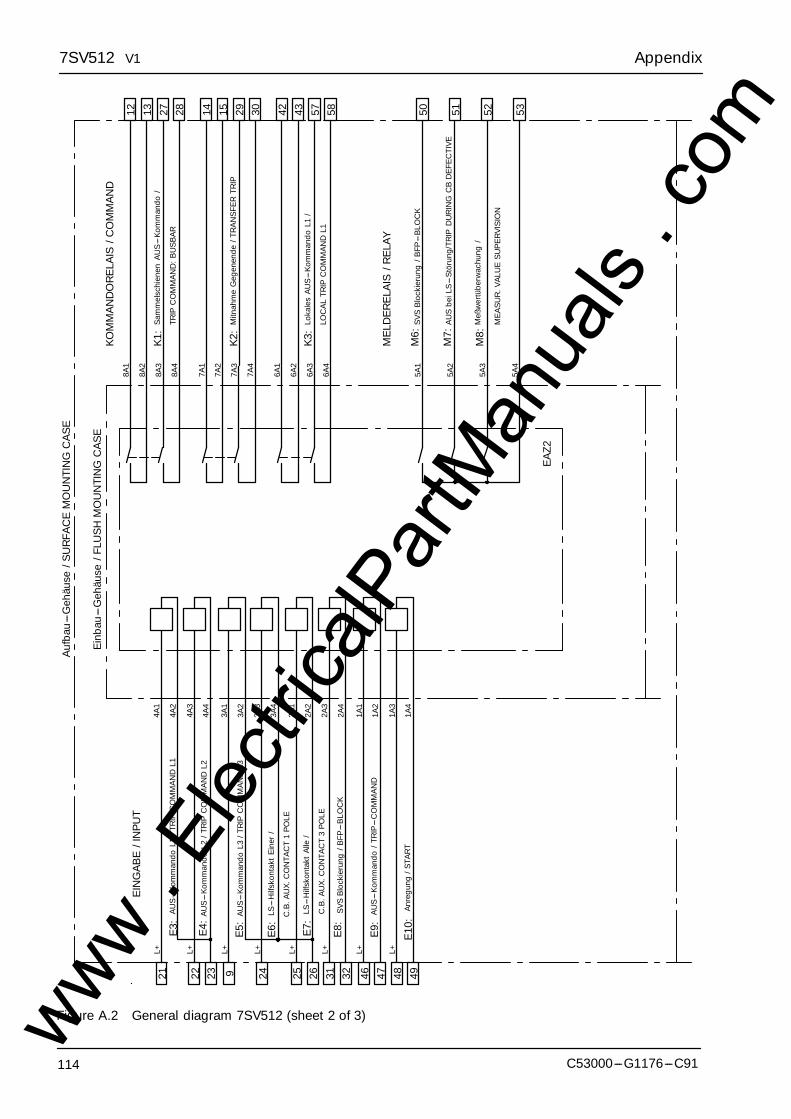
Appendix7SV512 V1
114 C53000---G1176---C91
4A1
4A2
21L+
E3:
4A3
4A4
22 23
L+
E4:
12 138A
2
8A1
28
K1:
8A4
8A3
14 157A
2
7A1
29 30
K2:
7A4
7A3
EA
Z2
Ein
bau
---G
ehäu
se/F
LUS
HM
OU
NTI
NG
CA
SE
Auf
bau
---G
ehäu
se/S
UR
FAC
EM
OU
NTI
NG
CA
SE
KOM
MA
ND
OR
ELA
IS/C
OM
MA
ND
ME
LDE
RE
LAIS
/RE
LAY
EIN
GA
BE
/IN
PUT
27
3A1
3A2
9 24
L+
E5:
3A3
3A4
L+
E6:
2A1
2A2
25 26
L+
E7:
2A3
2A4
31 32
L+
E8:
1A1
1A2
46 47
L+
E9:
1A3
1A4
48 49
L+
E10
:
42 436A
2
6A1
57 58
K3:
6A4
6A3
52 53
M8:
5A4
5A3
51M
7:5A
2
50M
6:5A
1
AU
S---
Kom
man
doL1
/TR
IPC
OM
MA
ND
L1
AU
S---
Kom
man
doL2
/TR
IPC
OM
MA
ND
L2
AU
S---
Kom
man
doL3
/TR
IPC
OM
MA
ND
L3
LS---
Hilf
skon
takt
Ein
er/
LS---
Hilf
skon
takt
Alle
/
SVS
Blo
ckie
rung
/BFP
---B
LOC
K
AU
S---
Kom
man
do/T
RIP
---C
OM
MA
ND
Anr
egun
g/S
TAR
T
Sam
mel
schi
enen
AU
S---
Kom
man
do/
TRIP
CO
MM
AN
D:
BU
SB
AR
Mitn
ahm
eG
egen
ende
/TR
AN
SFE
RTR
IP
SVS
Blo
ckie
rung
/BFP
---B
LOC
K
Loka
les
AU
S---
Kom
man
doL1
/
ME
AS
UR
.VA
LUE
SU
PE
RVI
SIO
N
Meß
wer
tübe
rwac
hung
/
LOC
AL
TRIP
CO
MM
AN
DL1
C.B
.AU
X.C
ON
TAC
T1
PO
LE
C.B
.AU
X.C
ON
TAC
T3
PO
LE
AU
Sbe
iLS
---S
töru
ng/T
RIP
DU
RIN
GC
BD
EFE
CTI
VE
Figure A.2 General diagram 7SV512 (sheet 2 of 3)www . El
ectric
alPar
tMan
uals
. com

Appendix7SV512 V1
C53000---G1176---C91 115
F---
SM
A5C
F---
SM
A5C
EPS
2
F---
SM
AF
---S
MA
EPS
2
5C4
5C3
5C1
5C2
Ein
bau
---G
ehäu
sem
itLW
L---
Mod
ulFL
US
HM
OU
NTI
NG
CA
SE
WIT
HFI
BR
EO
PTIC
INTE
RFA
CE
7SV5
12*-
--*C
7SV5
12*-
--*E
Auf
bau
---G
ehäu
sem
itLW
L---
Mod
ulS
UR
FAC
EM
OU
NTI
NG
CA
SE
WIT
HFI
BR
EO
PTIC
INTE
RFA
CE
7SV5
12*-
--*B
Figure A.3 General diagram 7SV512 (sheet 3 of 3)www . El
ectric
alPar
tMan
uals
. com
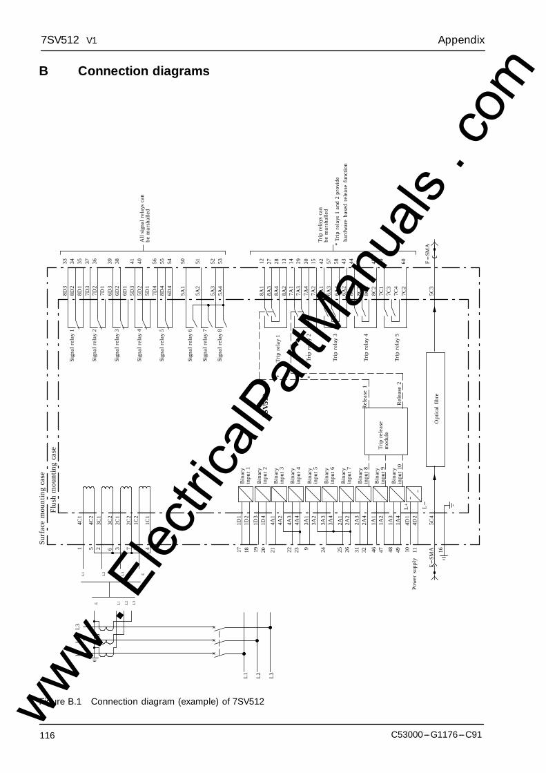
Appendix7SV512 V1
116 C53000---G1176---C91
B Connection diagrams
Bin
ary
8D3
8D2
8D1
7D3
7D2
6D3
7D1
6D2
6D1
5D3
5D2
5D1
7D4
8D4
6D4
5A1
5A2
5A3
5A4
8A1
8A3
8A4
8A2
7A1
7A3
7A4
7A2
6A1
6A3
6A4
6A2
8C1
8C3
8C4
8C2
7C1
7C3
7C4
7C2
5C3
33 34 35 37 36 39 38 41 40 56 55 54 50 51 52 53 12 27 1328 14 29 30 15 42 57 58 43 44
L---
45 59 60L
+
inpu
t1
Bin
ary
inpu
t2
Bin
ary
inpu
t3
Bin
ary
inpu
t4
Bin
ary
inpu
t5
Bin
ary
inpu
t6
Bin
ary
inpu
t7
Bin
ary
inpu
t8
Bin
ary
inpu
t9
Bin
ary
inpu
t10
� L1
� L2
� L3
� E
L3
L2
L1
L3
L2
L1
� L1
� L2
� L3
� E
1751 2 6 7 8 43 18 19 20 21 22 23 9 24 25 26 31 32 46 47 48 49 10 11
F---
SMA
Pow
ersu
pply
5C4
4D2
4D1
1A4
1A3
1A2
1A1
2A4
2A3
2A2
2A1
3A4
3A3
3A2
3A1
4A4
4A3
4A2
4A1
1D4
1D3
1D2
1D1
16
4C1
4C2
3C1
3C2
2C1
2C2
1C2
1C1
Surf
ace
mou
ntin
gca
se
Opt
ical
fibre
Rel
ease
2
Rel
ease
1
Sign
alre
lay
1
Sign
alre
lay
2
Sign
alre
lay
3
Sign
alre
lay
4
Sign
alre
lay
5
Sign
alre
lay
6
Sign
alre
lay
7
Sign
alre
lay
8
7SV
512
F---
SMA*
Trip
rela
ys1
and
2pr
ovid
e
Trip
rela
ysca
nbe
mar
shal
led
All
sign
alre
lays
can
bem
arsh
alle
d
Flu
shm
ount
ing
case
Trip
rela
y5
Trip
rela
y4
Trip
rela
y3
Trip
rela
y2
Trip
rela
y1
hard
war
eba
sed
rele
ase
func
tion
Trip
rele
ase
mod
ule
**
Figure B.1 Connection diagram (example) of 7SV512www . El
ectric
alPar
tMan
uals
. com
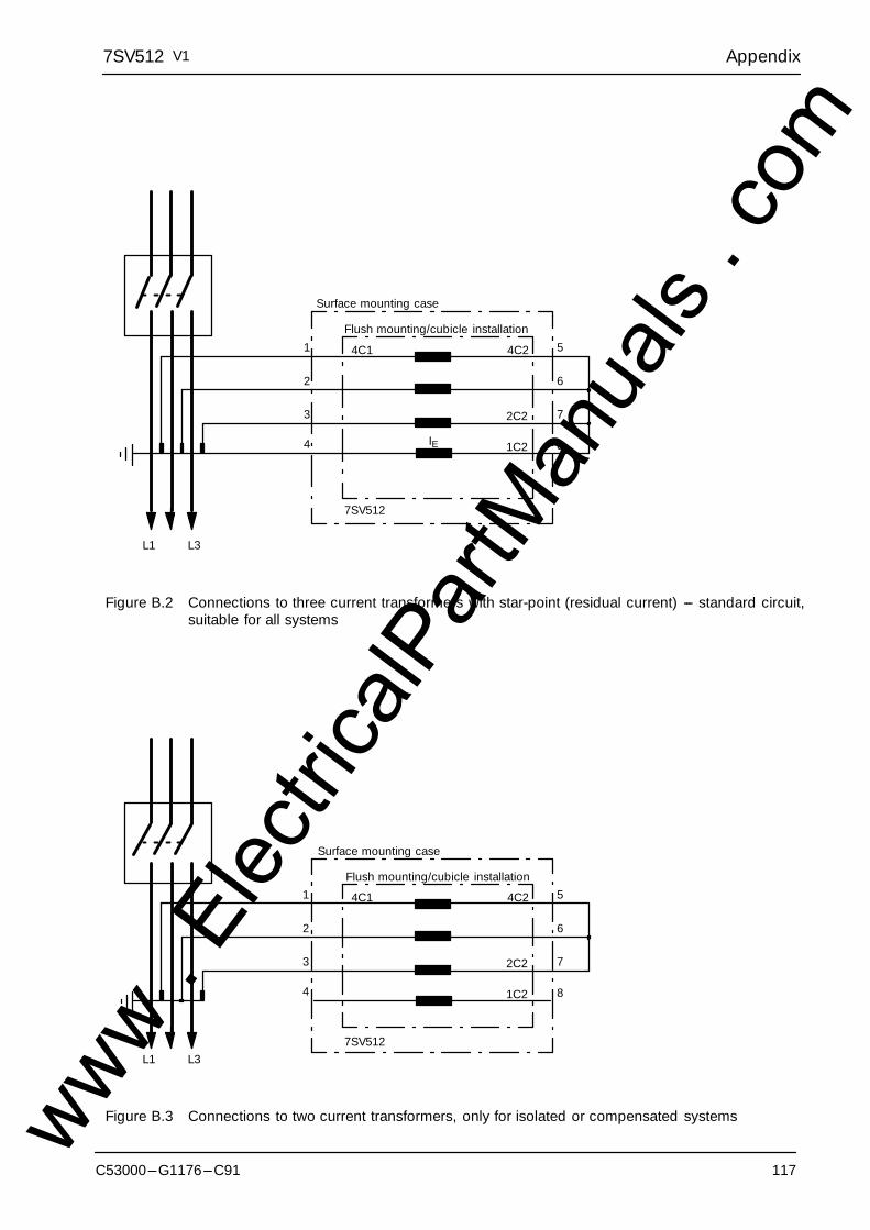
Appendix7SV512 V1
C53000---G1176---C91 117
3
2
1 5
6
72C1
4C1
3C1
2C2
4C2
3C2
L1 L2 L3
7SV512
4 81C1 1C2
Surface mounting case
Flush mounting/cubicle installation
IE
Figure B.2 Connections to three current transformers with star-point (residual current) --- standard circuit,suitable for all systems
3
2
1 5
6
72C1
4C1
3C1
2C2
4C2
3C2
L1 L2 L37SV512
4 81C1 1C2
Surface mounting case
Flush mounting/cubicle installation
Figure B.3 Connections to two current transformers, only for isolated or compensated systemswww . El
ectric
alPar
tMan
uals
. com
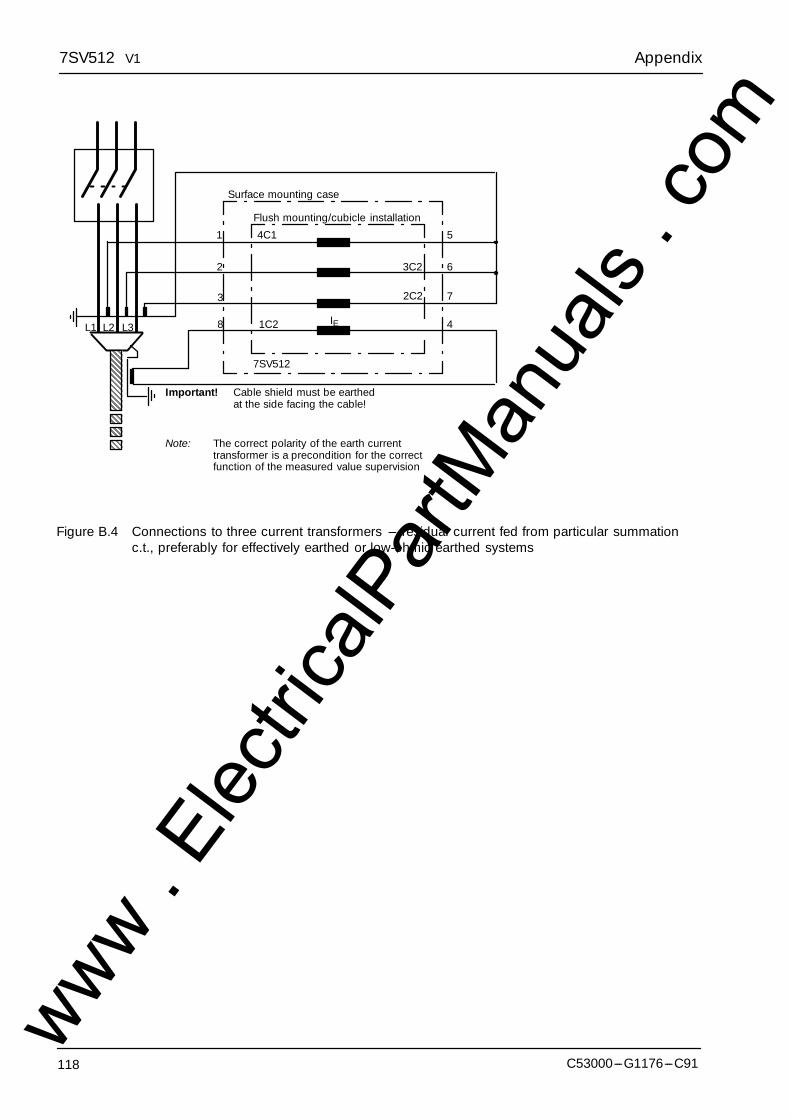
Appendix7SV512 V1
118 C53000---G1176---C91
3
2
1 5
6
72C1
4C1
3C1
2C2
4C2
3C2
7SV512
48 1C11C2L1 L2 L3
Important! Cable shield must be earthedat the side facing the cable!
Surface mounting case
Flush mounting/cubicle installation
IE
Note: The correct polarity of the earth currenttransformer is a precondition for the correctfunction of the measured value supervision
Figure B.4 Connections to three current transformers --- residual current fed from particular summationc.t., preferably for effectively earthed or low-ohmic earthed systems
www . El
ectric
alPar
tMan
uals
. com

Appendix7SV512 V1
C53000---G1176---C91 119
C Tables
Table C.1 Table of All Binary Inputs 120. . . . . . . . . . . . . . . . . . . . . . . . . . . . . . . . . . . . . . . . . . . . . . . . . . . . . . . . .
Table C.2 Table of All Binary Outputs 121. . . . . . . . . . . . . . . . . . . . . . . . . . . . . . . . . . . . . . . . . . . . . . . . . . . . . . .
Table C.3 Reference Table for Configuration Parameters 124. . . . . . . . . . . . . . . . . . . . . . . . . . . . . . . . . . . . . .
Table C.4 Reference Table for Functional Parameters 129. . . . . . . . . . . . . . . . . . . . . . . . . . . . . . . . . . . . . . . . .
Table C.5 Operational Control Facilities 131. . . . . . . . . . . . . . . . . . . . . . . . . . . . . . . . . . . . . . . . . . . . . . . . . . . . .
NOTE: The following tables list all data which are available in the maximum complement of the device.Dependent on the ordered model, only those data may be present which are valid for theindividual version.
NOTE: The actual tables are attached to the purchased relay.
www . El
ectric
alPar
tMan
uals
. com

7SV512 v1 Appendix
120 C53000-G1176-C91
Table C.1 Table of All Binary Inputs 7SV512
R Function can be marshalled to binary input (BI)
FNo. Abbreviation Meaning BI
1 not allocated No input function allocated R
5 >Time Synchro Synchronize internal real time clock R
6 >LED reset Reset stored led indicators R
7 >Start FltRec Start fault recording R
16 >CB Aux. L1 Circuit breaker aux. Contact: phase l1 R
17 >CB Aux. L2 Circuit breaker aux. Contact: phase l2 R
18 >CB Aux. L3 Circuit breaker aux. Contact: phase l3 R
19 >CB Aux. 3p C Cb aux. Contact: all poles closed R
20 >CB Aux. 1p C Cb aux. Contact: any pole closed R
21 >Annunc. 1 User defined annunciation 1 R
22 >Annunc. 2 User defined annunciation 2 R
23 >Annunc. 3 User defined annunciation 3 R
24 >Annunc. 4 User defined annunciation 4 R
31 >B/F on Switch on breaker failure protection R
32 >B/F off Switch offbreaker failure protection R
33 >Pol.Dis. on Switch on pole discrepancy supervision R
34 >Pol.Dis. off Switch off pole discrepancy supervis'n R
35 >Flt.Rec. on Switch on fault recording function R
36 >Flt.Rec. off Switch off fault recording function R
59 >ParamSelec.1 Parameter set selection 1 (with 60) R
60 >ParamSelec.2 Parameter set selection 2 (with 59) R
70 >Start Fault detection from feeder protection R
71 >Start N Earth fault detection from feeder prot R
72 >Trip General trip command from feeder prot. R
73 >Trip 3pole Trip 3 pole from feeder protection R
74 >Trip L1 Trip phase l1 from feeder protection R
75 >Trip L2 Trip phase l2 from feeder protection R
76 >Trip L3 Trip phase l3 from feeder protection R
77 >B/P block Block breaker failure protection R
78 >CB defect Circuit breaker defective (can't trip) R
www . El
ectric
alPar
tMan
uals
. com
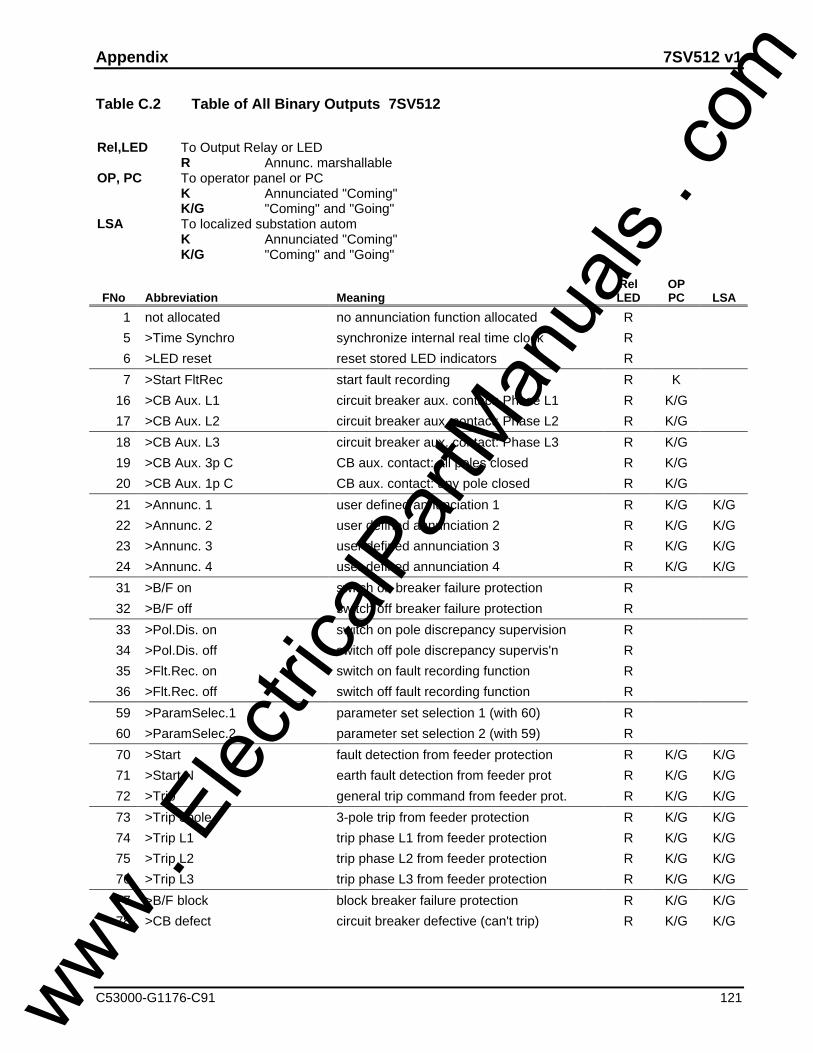
Appendix 7SV512 v1
C53000-G1176-C91 121
Table C.2 Table of All Binary Outputs 7SV512
Rel,LED To Output Relay or LEDR Annunc. marshallable
OP, PC To operator panel or PCK Annunciated "Coming"K/G "Coming" and "Going"
LSA To localized substation automK Annunciated "Coming"K/G "Coming" and "Going"
FNo Abbreviation MeaningRelLED
OPPC LSA
1 not allocated no annunciation function allocated R
5 >Time Synchro synchronize internal real time clock R
6 >LED reset reset stored LED indicators R
7 >Start FltRec start fault recording R K
16 >CB Aux. L1 circuit breaker aux. contact: Phase L1 R K/G
17 >CB Aux. L2 circuit breaker aux. contact: Phase L2 R K/G
18 >CB Aux. L3 circuit breaker aux. contact: Phase L3 R K/G
19 >CB Aux. 3p C CB aux. contact: all poles closed R K/G
20 >CB Aux. 1p C CB aux. contact: any pole closed R K/G
21 >Annunc. 1 user defined annunciation 1 R K/G K/G
22 >Annunc. 2 user defined annunciation 2 R K/G K/G
23 >Annunc. 3 user defined annunciation 3 R K/G K/G
24 >Annunc. 4 user defined annunciation 4 R K/G K/G
31 >B/F on switch on breaker failure protection R
32 >B/F off switch off breaker failure protection R
33 >Pol.Dis. on switch on pole discrepancy supervision R
34 >Pol.Dis. off switch off pole discrepancy supervis'n R
35 >Flt.Rec. on switch on fault recording function R
36 >Flt.Rec. off switch off fault recording function R
59 >ParamSelec.1 parameter set selection 1 (with 60) R
60 >ParamSelec.2 parameter set selection 2 (with 59) R
70 >Start fault detection from feeder protection R K/G K/G
71 >Start N earth fault detection from feeder prot R K/G K/G
72 >Trip general trip command from feeder prot. R K/G K/G
73 >Trip 3pole 3-pole trip from feeder protection R K/G K/G
74 >Trip L1 trip phase L1 from feeder protection R K/G K/G
75 >Trip L2 trip phase L2 from feeder protection R K/G K/G
76 >Trip L3 trip phase L3 from feeder protection R K/G K/G
77 >B/F block block breaker failure protection R K/G K/G
78 >CB defect circuit breaker defective (can't trip) R K/G K/G
www . El
ectric
alPar
tMan
uals
. com
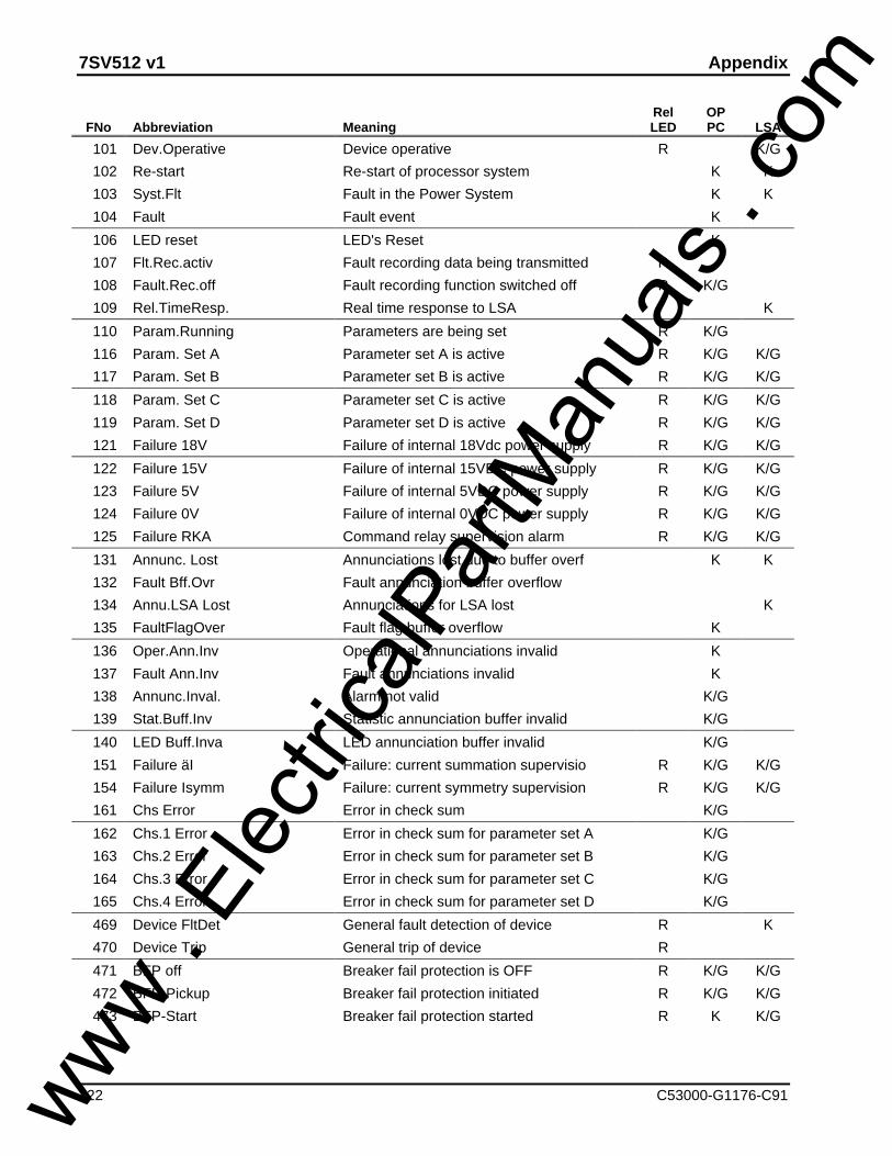
7SV512 v1 Appendix
122 C53000-G1176-C91
FNo Abbreviation MeaningRelLED
OPPC LSA
101 Dev.Operative Device operative R K/G
102 Re-start Re-start of processor system K K
103 Syst.Flt Fault in the Power System K K
104 Fault Fault event K
106 LED reset LED's Reset K
107 Flt.Rec.activ Fault recording data being transmitted R
108 Fault.Rec.off Fault recording function switched off R K/G
109 Rel.TimeResp. Real time response to LSA K
110 Param.Running Parameters are being set R K/G
116 Param. Set A Parameter set A is active R K/G K/G
117 Param. Set B Parameter set B is active R K/G K/G
118 Param. Set C Parameter set C is active R K/G K/G
119 Param. Set D Parameter set D is active R K/G K/G
121 Failure 18V Failure of internal 18Vdc power supply R K/G K/G
122 Failure 15V Failure of internal 15VDC power supply R K/G K/G
123 Failure 5V Failure of internal 5VDC power supply R K/G K/G
124 Failure 0V Failure of internal 0VDC power supply R K/G K/G
125 Failure RKA Command relay supervision alarm R K/G K/G
131 Annunc. Lost Annunciations lost due to buffer overf K K
132 Fault Bff.Ovr Fault annunciation buffer overflow
134 Annu.LSA Lost Annunciations for LSA lost K
135 FaultFlagOver Fault flag buffer overflow K
136 Oper.Ann.Inv Operational annunciations invalid K
137 Fault Ann.Inv Fault annunciations invalid K
138 Annunc.Inval. Alarm not valid K/G
139 Stat.Buff.Inv Statistic annunciation buffer invalid K/G
140 LED Buff.Inva LED annunciation buffer invalid K/G
151 Failure äI Failure: current summation supervisio R K/G K/G
154 Failure Isymm Failure: current symmetry supervision R K/G K/G
161 Chs Error Error in check sum K/G
162 Chs.1 Error Error in check sum for parameter set A K/G
163 Chs.2 Error Error in check sum for parameter set B K/G
164 Chs.3 Error Error in check sum for parameter set C K/G
165 Chs.4 Error Error in check sum for parameter set D K/G
469 Device FltDet General fault detection of device R K
470 Device Trip General trip of device R
471 BFP off Breaker fail protection is OFF R K/G K/G
472 BFP-Pickup Breaker fail protection initiated R K/G K/G
473 BFP-Start Breaker fail protection started R K K/G
www . El
ectric
alPar
tMan
uals
. com

Appendix 7SV512 v1
C53000-G1176-C91 123
FNo Abbreviation MeaningRelLED
OPPC LSA
474 BFP-Start. L1 Breaker fail protection START:Phase L1 R K K/G
475 BFP-Start. L2 Breaker fail protection START:Phase L2 R K K/G
476 BFP-Start. L3 Breaker fail protection START:Phase L3 R K K/G
500 Time del.init Time delay initiated R K
501 BFP-BFdefTrip Circuit breaker defective: TRIP R K K
502 BFP Trip L1 Local 1 pole trip: Phase L1 R K K
503 BFP Trip L2 Local 1 pole trip: Phase L2 R K K
504 BFP Trip L3 Local 1 pole trip: Phase L3 R K K
505 BFP Trip L123 Local 3 pole trip R K K
506 BFP CrossTrip Local Cross Trip R K K
507 BFP Trip BB BUSBAR TRIP R K K
508 BFP TransTrip Transfer trip / remote trip R K
509 BFP Block Breaker fail protection is blocked R K/G K
510 BFP T1 3pol Time delay for 3 pole faults expired R K K
511 BFP T1 1pol Time delay for 1 pole faults expired R K K
512 BFP T2 Curr Time delay for fault with current exp. R K K
513 BFP T2 Baux Time delay for faults with CB aux.exp. R K K
514 BFP Tend Faul Time delay for End-Fault prot.expired R K K
515 BFP T3 BRdef Time delay for flt with defect. CB exp R K
516 BFP HW Rel Trip release by hardware supervision R K/G K
600 Pol-Dis. OFF Pole discrepancy is switched OFF R K/G K/G
601 Pol-Dis.Start Pole discrepancy Start R K K/G
602 Pol-Dis. L1 Pole discrepancy Start: Phase L1 R K K
603 Pol-Dis. L2 Pole discrepancy Start: Phase L2 R K K
604 Pol-Dis. L3 Pole discrepancy Start: Phase L3 R K K
610 Pol-Dis. Trip Pole discrepancy TRIP R K K
900 Dev. Drop-off Device drop-off K
www . El
ectric
alPar
tMan
uals
. com

7SV512 v1 Appendix
124 C53000-G1176-C91
Table C.3 Reference Table for Configuration Parameters 7SV512
6000 MARSHALLING
6100 MARSHALLING BINARY INPUTS
6101 INPUT 1 6106 INPUT 6
6102 INPUT 2 6107 INPUT 7
6103 INPUT 3 6108 INPUT 8
6104 INPUT 4 6109 INPUT 9
6105 INPUT 5 6110 INPUT 10
www . El
ectric
alPar
tMan
uals
. com

Appendix 7SV512 v1
C53000-G1176-C91 125
6300 MARSHALLING LED INDICATORS
6301 LED 1 6304 LED 4
6302 LED 2 6305 LED 5
6303 LED 3 6306 LED 6
6200 MARSHALLING SIGNAL RELAYS
6201 RELAY 1 6205 RELAY 5
6202 RELAY 2 6206 RELAY 6
www . El
ectric
alPar
tMan
uals
. com

7SV512 v1 Appendix
126 C53000-G1176-C91
6203 RELAY 3 6207 RELAY 7
6204 RELAY 4 6208 RELAY 8
6300 MARSHALLING LED INDICATORS
6301 LED 1 6302 LED 2
6400 MARSHALLING TRIP RELAYS
6401 TRIP REL. 1 6404 TRIP REL. 4
6403 TRIP REL. 3 6405 TRIP REL. 5
www . El
ectric
alPar
tMan
uals
. com

Appendix 7SV512 v1
C53000-G1176-C91 127
6402 TRIP REL. 2
6900 LSA CONFIGURATION
6902 LSA BAUDR.
7000 OPERATING PARAMETERS
7001 LANGUAGE 7006 OPER. 2nd L
7002 OPER.BAUDR 7007 FAULT 1st L
7003 DATE FORM. 7008 FAULT 2nd L
7004 FAULT IND. 7009 DEVICE ADD.
www . El
ectric
alPar
tMan
uals
. com

7SV512 v1 Appendix
128 C53000-G1176-C91
7005 OPER. 1st L 7010 FEEDER ADD.
7800 SCOPE OF FUNCTIONS
7828 FAULT RECRD 7885 PARAM.C/O
7838 POLE DISCR 7899 FREQUENCY
7869 LSA
www . El
ectric
alPar
tMan
uals
. com

Appendix 7SV512 v1
C53000-G1176-C91 129
Table C.4 Reference Table for Functional Parameters 7SV512
1000 PARAMETERS
1100 POWERSYSTEM DATA
1105 In PRIMARY 1115 T-TRIPmin. 10 A min. 0.00 smax. 50000 _______ max. 32.00 _______
1112 Ie/Iphmin. 0.10max. 20.00 _______
1200 BREAKER FAILURE PROT.
1201 BREAK FAIL 1212 T2-CU RRENTON [ ] min. 0.00 sOFF [ ] max. 32.00/ì _______
1202 I-BF 1213 T2-CB-AUX.min. 0.05 I/In min. 0.00 smax. 4.00 _______ max. 32.00/ì _______
1203 TRIP CRoff 1214 T3-CB-DEF.YES [ ] min. 0.00 sNO [ ] max. 32.00/ì _______
1204 TRIP 1POLE 1220 T-ENDFAULTYES [ ] min. 0.00 sNO [ ] max. 32.00/ì _______
1205 T1-1POLE 1221 BLOCK MONmin. 0.00 s YES [ ]max. 32.00/ì _______ NO [ ]
1206 T1-3POLE 1222 T-BLOCKMONmin. 0.00 s min. 0.05 smax. 32.00/ì _______ max. 32.00/ì _______
1211 T-TRIP-BB 1223 PLAUS 1POLT1 + T2 [ ] RESIDUAL CURRENT [ ]T2 [ ] NEG.SEQ. CURRENT [ ]
www . El
ectric
alPar
tMan
uals
. com
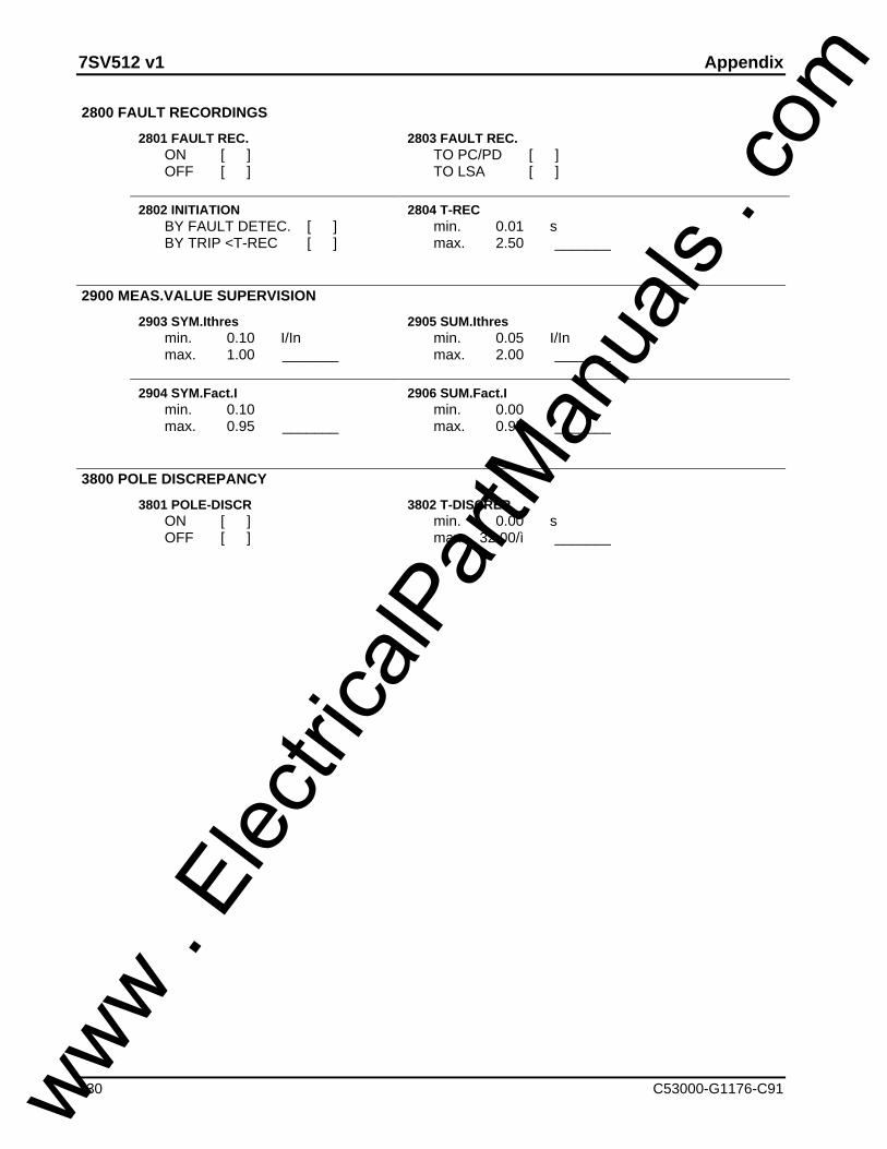
7SV512 v1 Appendix
130 C53000-G1176-C91
2800 FAULT RECORDINGS
2801 FAULT REC. 2803 FAULT REC.ON [ ] TO PC/PD [ ]OFF [ ] TO LSA [ ]
2802 INITIATION 2804 T-RECBY FAULT DETEC. [ ] min. 0.01 sBY TRIP <T-REC [ ] max. 2.50 _______
2900 MEAS.VALUE SUPERVISION
2903 SYM.Ithres 2905 SUM.Ithresmin. 0.10 I/In min. 0.05 I/Inmax. 1.00 _______ max. 2.00 _______
2904 SYM.Fact.I 2906 SUM.Fact.Imin. 0.10 min. 0.00max. 0.95 _______ max. 0.95 _______
3800 POLE DISCREPANCY
3801 POLE-DISCR 3802 T-DISCREPON [ ] min. 0.00 sOFF [ ] max. 32.00/ì _______
www . El
ectric
alPar
tMan
uals
. com

Appendix 7SV512 v1
C53000-G1176-C91 131
Table C.5 Operational Control Facilities 7SV512
8000 Device Control
8100 Setting Real Time Clock
8101 DATE/TIME8102 DATE8103 TIME8104 DIFF. TIME
8200 Reset
8201 RESET LED ?8202 RESET COUNTERS ?8203 RESET TOTAL Isc ?8204 RESET OPERAT.ANNUNC. ?8205 RESET FAULT ANNUNC. ?
8500 Parameter Change Over
8501 ACTIV PARAM8503 ACTIVATION SET A
SET BSET CSET D
8510 COPY ? ORIG.SET->SET A8511 COPY ? ORIG.SET->SET B8512 COPY ? ORIG.SET->SET C8513 COPY ? ORIG.SET->SET D8514 COPY ? SET A -> SET B8515 COPY ? SET A -> SET C8516 COPY ? SET A -> SET D8517 COPY ? SET B -> SET A8518 COPY ? SET B -> SET C8519 COPY ? SET B -> SET D8520 COPY ? SET C -> SET A8521 COPY ? SET C -> SET B8522 COPY ? SET C -> SET D8523 COPY ? SET D -> SET A8524 COPY ? SET D -> SET B8525 COPY ? SET D -> SET C
ON/OFF CONTROL
www . El
ectric
alPar
tMan
uals
. com

7SV512 v1 Appendix
132 C53000-G1176-C91
1200
1201 BREAK-FAIL ONOFF
2800
2801 FAULT REC. ONOFF
3800
3801 POLE-DISCR ONOFF
www . El
ectric
alPar
tMan
uals
. com
Corrections/Suggestions7SV512 V1.0
133C53000---G1176---C91---3
To
SIEMENS AKTIENGESELLSCHAF T
Dept. EV S SUP 21
D---13623 BERLIN
Germany
From________________________________________Name
________________________________________Company/Dept.
________________________________________Address
________________________________________Telephone no.
________________________________________
Dear reader,
printing errors can never be entirely eliminated:therefore, should you come across any whenreading this manual, kindly enter them in thisform together with any comments or sug-gestions for improvement that you may have.
Corrections/Suggestions
www . El
ectric
alPar
tMan
uals
. com

www . El
ectric
alPar
tMan
uals
. com

www . El
ectric
alPar
tMan
uals
. com

Order No. C53000---G1176---C91---3Available from: LZF Fürth---BislohePrinted in the Federal Republic of GermanyAG 0499 0.2 FO 128 En
Copying of this document and giving it to others and the useor communication of the contents thereof, are forbidden with-out express authority. Offenders are liable to the payment ofdamages. All rights are reserved in the event of the grant ofa patent or the registration of a utility model or design.Subject to technical alteration
Siemens Aktiengesellschaftwww . El
ectric
alPar
tMan
uals
. com