
NUMERICAL AND EXPERIMENTAL INVESTIGATION OF...
12
THE 19 TH INTERNATIONAL CONFERENCE ON COMPOSITE MATERIALS 1 Introduction Bolted joints have been extensively used on aircraft since the dawn of aviation and, even with the recent and widespread introduction of composite materials, still play a key role in aeronautical structures. Along with high strength and versatility, this technology offers the possibility to disassemble the joint for inspection and maintenance or to access concealed parts of the structure. During the manufacturing of structures, errors can occur. If the structure is expensive, it is economically and environmentally important to attempt a repair with the aim of restoring the designed mechanical performance. A particular error that can occur in the production of aeronautical structures, such as a wing or fuselage, is the slight misplacement of drilled holes in a bolted connection between large composite plates. Such errors can be repaired through the use of metallic inserts. This paper presents a finite element (FE) and experimental investigation of the static mechanical behaviour of single-lap composite joints, with countersunk bolts, repaired with metallic inserts. The FE model has been used to help interpret the results obtained from the experiments. 2 Literature Review Limited literature can be found on the use of inserts as a repair technique in composite fastened joints. Previous studies focused on the introduction of bonded inserts to increase the bearing strength of fastened joints. Camanho and Matthews [1] investigated the use of bonded metallic inserts to improve the strength of double-lap composite bolted joints. It was found that bonded metallic inserts reduced the stress concentrations in the vicinity of the hole. Nevertheless, the failure of the adhesive took place far before the ultimate load of the joint, hence, providing little improvement. Camanho et al. [2] found that the development of damage was delayed using bonded inserts due to the new regions of load transfer that were created. Bonded inserts were able to transfer the load to the laminate through the whole surface of the hole instead of approximately half the hole surface. However, after the failure of the adhesive, the stresses were not relieved anymore and the laminate exhibited composite bearing failure. Mazraehshahi et al. [3] focused their study on the influence of the geometry of the insert on the stress field of composite plates. The effects of different thicknesses, clearances and materials were studied by means of a three-dimensional finite element model. They concluded that increasing clearances lead to higher radial stresses. In addition, the reduction of stress concentrations when using thicker inserts was confirmed by this study. 3 Investigated Configurations The analysed configurations consisted of single-lap joints made of unidirectional carbon fibre reinforced plastic (CFRP) plates, titanium countersunk bolts and steel nuts, tested under tensile loading. The single-lap joint configurations consisted of two bolts contrary placed, with the fastener heads on different sides of the joint as shown in Fig. 1. Two different composite plate thicknesses and two different bolt reference configurations were used per each thickness, named standard and swapped. In the standard single-lap joint configuration, the countersunk heads of the bolts were placed towards the run-out of the plates (critical location for shear- out failure; Figs 1 and 3). On the contrary, in the swapped single-lap joint configuration, the countersunk heads of the bolts were placed in the internal holes of the plates (critical location for net- section failure; Fig. 2). Two support composite plates were also bonded to the main plates of the joint to avoid any eccentricity in the application of the external tensile load. The stacking sequence of the CFRP plates was [±45/0/90/∓45/0/90] S and [(±45/0/90/∓45/0/90) 2 ] S for the thin and thick NUMERICAL AND EXPERIMENTAL INVESTIGATION OF COMPOSITE BOLTED JOINTS REPAIRED WITH INSERTS E.I. Avgoulas*, S. Tejada, C. Stocchi, P. Robinson, S. Pinho Aeronautics, Imperial College London, London, UK, * Corresponding author ([email protected]) Keywords: composite joints, countersunk bolts, fasteners, repair, insert, fem, testing
-
Upload
truongdieu -
Category
Documents
-
view
218 -
download
0
Transcript of NUMERICAL AND EXPERIMENTAL INVESTIGATION OF...

THE 19TH
INTERNATIONAL CONFERENCE ON COMPOSITE MATERIALS
1 Introduction
Bolted joints have been extensively used on aircraft
since the dawn of aviation and, even with the recent
and widespread introduction of composite materials,
still play a key role in aeronautical structures. Along
with high strength and versatility, this technology
offers the possibility to disassemble the joint for
inspection and maintenance or to access concealed
parts of the structure.
During the manufacturing of structures, errors can
occur. If the structure is expensive, it is
economically and environmentally important to
attempt a repair with the aim of restoring the
designed mechanical performance. A particular error
that can occur in the production of aeronautical
structures, such as a wing or fuselage, is the slight
misplacement of drilled holes in a bolted connection
between large composite plates. Such errors can be
repaired through the use of metallic inserts.
This paper presents a finite element (FE) and
experimental investigation of the static mechanical
behaviour of single-lap composite joints, with
countersunk bolts, repaired with metallic inserts.
The FE model has been used to help interpret the
results obtained from the experiments.
2 Literature Review
Limited literature can be found on the use of inserts
as a repair technique in composite fastened joints.
Previous studies focused on the introduction of
bonded inserts to increase the bearing strength of
fastened joints. Camanho and Matthews [1]
investigated the use of bonded metallic inserts to
improve the strength of double-lap composite bolted
joints. It was found that bonded metallic inserts
reduced the stress concentrations in the vicinity of
the hole. Nevertheless, the failure of the adhesive
took place far before the ultimate load of the joint,
hence, providing little improvement. Camanho et al.
[2] found that the development of damage was
delayed using bonded inserts due to the new regions
of load transfer that were created. Bonded inserts
were able to transfer the load to the laminate through
the whole surface of the hole instead of
approximately half the hole surface. However, after
the failure of the adhesive, the stresses were not
relieved anymore and the laminate exhibited
composite bearing failure.
Mazraehshahi et al. [3] focused their study on the
influence of the geometry of the insert on the stress
field of composite plates. The effects of different
thicknesses, clearances and materials were studied
by means of a three-dimensional finite element
model. They concluded that increasing clearances
lead to higher radial stresses. In addition, the
reduction of stress concentrations when using
thicker inserts was confirmed by this study.
3 Investigated Configurations
The analysed configurations consisted of single-lap
joints made of unidirectional carbon fibre reinforced
plastic (CFRP) plates, titanium countersunk bolts
and steel nuts, tested under tensile loading. The
single-lap joint configurations consisted of two bolts
contrary placed, with the fastener heads on different
sides of the joint as shown in Fig. 1. Two different
composite plate thicknesses and two different bolt
reference configurations were used per each
thickness, named standard and swapped. In the
standard single-lap joint configuration, the
countersunk heads of the bolts were placed towards
the run-out of the plates (critical location for shear-
out failure; Figs 1 and 3). On the contrary, in the
swapped single-lap joint configuration, the
countersunk heads of the bolts were placed in the
internal holes of the plates (critical location for net-
section failure; Fig. 2). Two support composite
plates were also bonded to the main plates of the
joint to avoid any eccentricity in the application of
the external tensile load. The stacking sequence of
the CFRP plates was [±45/0/90/∓45/0/90]S and
[(±45/0/90/∓45/0/90)2]S for the thin and thick
NUMERICAL AND EXPERIMENTAL INVESTIGATION OF COMPOSITE BOLTED JOINTS REPAIRED WITH INSERTS
E.I. Avgoulas*, S. Tejada, C. Stocchi, P. Robinson, S. Pinho
Aeronautics, Imperial College London, London, UK, * Corresponding author ([email protected])
Keywords: composite joints, countersunk bolts, fasteners, repair, insert, fem, testing

specimens, respectively. Thus, both thin and thick
laminates consisted of 50% of ±45o plies, 25% of 0
o
plies and 25% of 90o. The ply thickness of the
material used was nominally 0.187mm [4], yielding
a nominal laminate thickness after curing of ~3 mm
and ~6 mm. Bolt types EN6114K4-4 and
EN6114K4-8 were used. The bolts for both thin and
thick configurations had identical diameter (6.35
mm; (1/4")) and countersunk head but different
shank length. In all the configurations, nut type
ASNA2536-4 was used and the repair inserts were
made of aluminium. The investigated configurations
were:
reference joints; without insert, designed to
have bearing/fastener failure (Fig. 1). Two
swapped and two standard joint configurations
for both composite plate thicknesses were
studied (i.e. a total of four different
configurations);
joints with coaxial (symmetric) inserts; an
aluminium insert with coaxial internal and
external profiles was located around a
countersunk bolt head. This is a repair
technique for a joint with a hole drilled in the
correct position but with an oversized diameter.
The cases of inserts with wall thicknesses of
1.07 and 3.32 mm were studied (Fig. 2) and for
both the thin and thick composite plates (i.e. a
total of four different configurations). Coaxial
inserts were placed at the internal hole of the
joint in order to study possible net-tension
failures. Thus the swapped joint configuration
was used for all the coaxial inserts;
joints with non-coaxial (asymmetric) inserts; an
aluminium insert with non-coaxial internal and
external profiles was located around a
countersunk head. This is a repair technique for
a joint with axis of a drilled hole not positioned
in the correct location. Three cases were studied
for both thin and thick composite plates (i.e. a
total of 6 different configurations). The inserts
were positioned towards the run-out (Fig. 3),
towards the other bolt and towards the side of
the composite plate. Non-coaxial inserts were
placed close to the run-out to investigate
possible shear out failures. Thus the standard
joint configuration was used for all the non-
coaxial inserts.
3.1 Nomenclature
A numerical code allows a fast identification of the
configuration and an alphabetical code provides a
full description of the sample. The alphabetical code
is based on abbreviations that indicate the position
of the bolts (standard or swapped), the thickness of
the composite plates, the size and type of the insert
and the positioning for the non-coaxial inserts (Table
1). A complete list of the specimens under
investigation is presented in Table 2, which relates
the numerical and alphabetical codes. The different
insert configurations used are illustrated in Fig 4.
4 Finite Element Investigation
Highly-detailed, three-dimensional, non-linear
finite-element models of composite bolted joints
repaired with metallic inserts (Fig. 5) were
developed with the finite element software Abaqus
6.10, based on the work published by Stocchi et al.
[5].
A three-dimensional model was required to study the
joint behaviour due to the three dimensional stress
state introduced by the preload, the hole edge
stresses and the secondary bending [6]. In order to
provide a time-effective means of evaluating the
repaired joint behaviour, a script was coded in
Python to automatically generate the FE models for
the desired configurations.
The mesh density and the element refinement were
found as the best compromise between convergence,
accuracy and computational cost (Fig. 5). The model
is able to account for the effect of the clearances
between the bolt, the insert and the composite plates
(Fig. 6).
The material modelling comprised of an elasto-
plastic behaviour for the metallic materials and
orthotropic elastic behaviour for the CFRP. A full
definition of all the contacts between the plates, the
bolts and the insert was implemented. The FE model
was validated against the results obtained during the
experimental program. The analysis has a dynamic-
implicit formulation and was divided in two steps:
1. the clamping force was applied to the bolts
using the Bolt Load keyword, which shrinks
the length of the shank to introduce the
desired preload.
2. grips were simulated by two rigid bodies
located at the edges of the model and
associated with two reference points. The
tensile load was applied imposing a linear
displacement to one of these points whereas
the other was kept fixed.
Several parametric studies were conducted to
investigate the effect of the hole-insert-bolt
clearances and of the height of the insert on the joint
mechanical behaviour.

5 Experimental Procedure
5.1 Specimen Manufacture
The two different thicknesses of the quasi-isotropic
laminates were manufactured and cured according to
the prepreg manufacturer recommended procedure.
Once manufactured, all the panels were
ultrasonically (C-scan) tested in order to ensure that
no defects were present (e.g. delaminations,
inclusions, voids). The support plates were bonded
to the main plates using FM300 film adhesive.
Before bonding, the surfaces were sand-blasted and
cleaned. The specimens were obtained by dry-
cutting the panels into strips with a nominal width of
50.8 mm and the holes were drilled using tungsten
carbide drills.
The accurate positioning of the insert in the joint
was of paramount importance in order to correctly
evaluate the behaviour of the joint with the insert.
Therefore, great care was given to the positioning of
the insert into the hole. In all the joint
configurations, the length of the insert was adjusted
(by abrading the lower surface), so that it was
0.2 mm shorter than the thickness of the composite
plate. All bolts were tightened with a torque of
7.4 Nm. Fig. 7 shows an assembled specimen with a
non-coaxial insert located towards the run-out of the
plate. Two specimens were manufactured for each
investigated configurations mentioned in section 3.
5.2 Tensile Testing
Static tensile tests were performed on two specimens
for each configuration (Fig. 8). A test machine
(Instron 4505) was used to perform the tensile tests,
using a 100 kN load cell. A fixed displacement rate
of 1 mm/min was used for all the tests.
The specimens were tested until final failure,
passing through a partial unload-reload loop. The
thin and thick specimens were loaded up to 18 kN
and 27 kN, respectively, then unloaded to 10 kN and
finally re-loaded to failure. The load and
displacement readings were taken from the machine
load cell and LVDTs, respectively (Fig. 8).
5.3 Non Destructive Evaluation
In addition to visual observation, a post-failure
analysis of the failure of the specimens was
conducted, using X-Rays. Since the X-Ray linear
absorption coefficient of CFRP is relatively low, an
opaque organic X-Ray penetrant (dibromomethane)
was used to highlight the damage in the vicinity of
the holes. Each specimen was immersed in the
penetrant for 2 min (contact time) and left to dry for
20 mins (dwell time) before being X-Ray tested.
6 Results and Discussion
6.1 Stages in Load-Displacement Behaviour
Both the FE investigation and the experimental
program highlighted five stages in the behaviour of
the repaired composite joints, as observed by
Stocchi et al. [5] for joints without inserts. The
stages were (i) No-Slip, (ii) Slip, (iii) Full Contact,
(iv) Damage and (v) Final Failure. The different
stages can be clearly identified in the sample load-
displacement curve of the test 3.6/1 st-tk-L-asym-sd
(Fig. 9).
In the No-slip stage, the joint exhibits the highest
stiffness of the five stages. Stocchi et al. [5] showed
that, in the No-slip stage, the load is fully transferred
through friction. In this stage the shank of the bolt is
not in contact with the plate or the straight surface of
the insert and no relative movement between the
plates occurs. Therefore, the stiffness of the joint
depends on the stiffness of the CFRP plates. It can
be seen from the Load-Displacement graph (Fig. 10)
that the length of this stage was approximately the
same for reference and repaired joints. The Slip stage starts when the external force exceeds
the maximum load that can be transferred only
through friction between the plates. From this point
forward, the plates start to slip and the clearance
between holes and bolts is progressively reduced.
There is no significant increase in the carried load
and a substantial drop in the stiffness occurs. The
length of the Slip stage is therefore linked to the
amount of clearance present in the joint. This is in
full accordance with the numerical and experimental
work of McCarthy et al. [7, 8] and Stocchi et al. [5].
The smooth stiffness transition between the Slip and
the Full Contact stage is due to the progressively
increasing contact between the bolt, insert and hole.
The straight holes of the plate are usually the first to
come in contact with the shank of the bolt, followed
by the contact of the straight portion of the
countersunk hole with the straight surface of the
insert. The order of the contact sequence depends on
the relative clearances between the plate, insert and
bolt.
In the Full Contact stage the majority of the load is
transferred through the contact between the shank of
the bolts and the straight portion of the holes and the
inserts. The local compliance of the aforementioned
contact leads to lower stiffness compared to the No-
Slip stage.
The Damage stage is characterised by a progressive
loss of stiffness caused by the metallic components
undergoing extensive yielding together with the
onset and propagation of bearing damage in the
composite plates.
Eventually, Final Failure stage results in a sudden
drop in the load carried by the joint. The failure can
be attributed to a single failure mode such as bolt
head failure or to a combination of different failure
modes.
6.2 Numerical Results: Bolt/Insert Failures and
Parametric Studies
High concentration of stress and plastic strain was
found at the fillets of the bolt head and insert, and at
the straight contact area of the latter. The application
of the 10 kN bolt preload appears to be enough to
plasticise extensively the insert and to cause a more
localised yielding of the bolts. The yielding
subsequently progresses to the straight portion of the
insert with the application of the tensile loading. The
bolt shank section at the height of the faying surface
also exhibited extensive plastic strain due to high
shear stresses.
The numerical results indicated that the
configurations with inserts exhibit a similar response
to the reference configurations. Thin configurations
showed lower stiffness than reference ones in the
Full-Contact phase probably due to the extensive
yielding of the inserts that was also observed during
the experimental program. The joints with non-
coaxial inserts did not exhibit a different behaviour
except for the 3.5 st-tn-L-asym-sd configuration
samples with non-coaxial inserts which exhibited a
softening phase larger than expected (Fig. 11). This
behaviour was also present during the testing of the
samples and it seems that it could have been caused
by the rotation of the insert around its external
profile axis, due to the moment generated by the
resultant forces of the bolt and plate on the insert
(Fig. 12). The rotation of the insert was limited by
the friction forces and the presence of the bolt. A parametric study was performed in order to assess
the impact of the height of the insert on the preload
distribution due to the reduction of the distance
between the insert and the lower plate when the
preload is applied (Fig. 13). The analyses were
performed using the 3.1 st-tn-L-asym-out
configuration. A first FE analysis was carried out
with a 0.3 mm gap between the bottom end of the
insert and the opposite composite plate so that no
contact between the insert and plate could occur.
Subsequently, the 3.1 st-tn-L-asym-out
configuration was analysed with no gap between the
insert and the lower plate. The numerical results
showed that the configurations had similar responses
and that the No-Slip and Slip phases were clearly
defined in both configurations. Therefore, when no
gap was present, the preload compressed the insert
against the lower plate and the friction between the
insert and the lower plate was responsible for the
No-Slip phase (Fig. 14). Hence, the height of the
insert did not have a noticeable impact in load
response of the joint for this specific type of insert
repair and similar coefficients of friction between
both plates and between the insert and the bottom
plate.
Clearances are known to play an important role in
the distribution of the load in multi-bolt composite
joints [9]. Therefore, the influence of the clearances
on the joints with inserts was investigated using the
parametric capabilities of the FEM model. Two
different scenarios were studied for the
3.3 st-tn-L-asym-in. Clearances of 0.2 mm and
0.3 mm between the insert and the plate were
considered. First, maintaining at 0.05 mm the
clearances at the other bolt and, second, by having at
the other bolt the same clearance of the insert
(i.e. 0.2 mm and 0.3 mm). The results showed that a
clear sliding phase was present for the second
scenario whereas almost no clearance was found in
the response behaviour for the first scenario (Figs 15
and 16). The results also showed that contact
stresses increased in both scenarios in comparison
with the nominal 3.3 st-tn-L-asym-sd configuration
with a clearance of 0.09 mm in the insert. For a
tensile load of 15 kN, the contact stresses increased
by 8% and 31% for the first and second scenarios
respectively with a gap of 0.3 mm.
Since the clearances at the insert for the first
scenario were around four to six times the clearances
at the bolt, contact occurred at the bolt with no insert
far earlier than for the one with the insert, showing a
response with a short sliding phase and a moderate
increase of the stresses due to the unequal sharing of
the load, which is in line with previous studies on
clearances [7]. For the second scenario, since insert
and bolt had large clearances, both plates had to
slide further until Full-Contact was achieved,
resulting in a considerably longer sliding phase and
a consequent loss of stiffness. Higher clearances
reduced the bolt-plate contact area [5, 8], partially
leading to an increase of 31% in the contact stresses.
In addition, higher clearances resulted in further

indentation of the bolts due to larger secondary
bending [10].
6.3 Experimental Results on Bolt/Insert Failures
6.3.1 Joint behaviour
Load versus Displacement graphs were obtained
from all the tests. The displacements were calculated
from the LVDTs (Fig. 8).
The test machine cross head displacement was
significantly larger than the displacement
determined from the LVDT readings due to the
compliance of the machine.
6.3.2 Unload-Reload loop
The unload-reload loops were characterised by a
joint stiffness similar to the No-Slip stage. The
stiffness increase with respect to the Full-Contact
stage is due to the friction between the two plates
which limits the relative movement of the plates. As
for the No-Slip stage, in the unload-reload loop the
change in the load is mainly transferred by friction.
Therefore, the different paths followed by the
unload-reload loop can be attributed to the limited
amount of slip between the plates. The area between
the load paths represents the energy dissipation due
to friction. Finally, the limited plate movement
results in the initial and final points of the unload-
reload loop being nearly coincident.
6.3.3 Maximum Load Comparison
The average maximum load for the standard and
swapped thin reference joint configurations were
32% and 35% lower than the corresponding thick
joints. Therefore, the average tensile stresses
reached in the thin composite specimens were on
average 36% and 30% higher than for the thick
specimens of the standard and swapped
configurations, respectively. Hence, the thin
specimens exhibited better efficiency than the
corresponding thick ones.
However, the failure modes found for both thick and
thin reference configurations were bolt head failure
instead of composite failure, and therefore, the thin
specimens, although more efficient, led to bolt
failure for lower tensile loads than the thick
specimens.
This premature bolt head failure found for the thin
specimens can be explained by the larger secondary
bending suffered by the thin specimens, which resulted in a greater tilting of the bolts inside the
holes. Taking a closer look at the bolt head failure
present for all the reference samples (except for
1.1/1 st-tn-Ref, where bolt pull through failure
occurred), it was concluded that the head failure
occurred when cracks propagated upwards from the
fillet of the countersunk head (Fig. 17). This bolt
head failure is driven by the forces acting on the
countersunk head of the bolt. In thick specimens,
stresses were more evenly distributed along the area
of contact between the bolt and the composite plate.
On the contrary, in thin specimens, the larger tilting
of bolts reduced the area of contact at the shank,
increasing the contact stresses at the head and the
fillet of the bolt, and thus, leading to the premature
failure of the bolts.
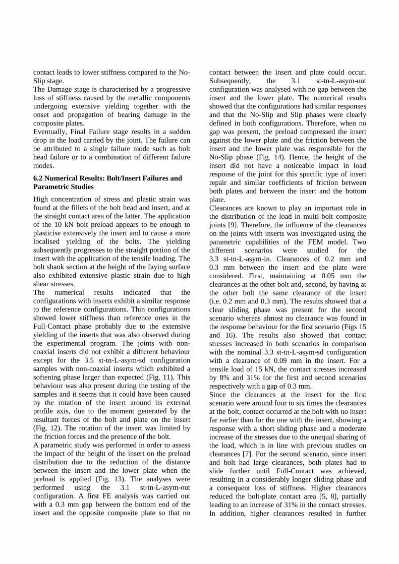
Small differences in the strength were generally
found between configurations with inserts and their
respective reference configurations. Figs 18-21 show
the average maximum load for all the configurations
under study. The range of each error bar shows the
two load values obtained for the two tested
specimens for each configuration. Error bars are not
available for configurations 3.3 st-tn-L-asym-in,
3.5 st-tn-L-asym-sd, 3.2 st-tk-L-asym-out and
3.6 st-tk-L-asym-sd, since only one specimen was
tested for these configurations. The numbers in
brackets inside the bars of Figs 18-21 refer to the
percentage difference between the average
maximum load obtained for the specific
configuration with the insert and for the
corresponding reference joint. The largest difference
in strength was observed for the thin plate specimen
of 3.5 st-tn-L-asym-sd configuration, which
exhibited a maximum load of 15% lower than the
1.3 st-tn-Ref reference joint (Fig. 20). The rest of the
configurations showed consistent results between
reference and repaired joints with the average
maximum loads fluctuating between -6% and +7%
compared with the reference configurations. Even if
the difference was generally limited, 2.2 st-tk-S-sym
(Fig. 19) and 2.3 sw-tn-L-sym (Fig. 18) were the
only configurations with inserts that showed an
improvement on the maximum load. Configurations
3.1 st-tn-L-asym-out (Fig. 20) and 3.6 st-tk-L-asym-
sd (Fig. 21) exhibited almost no difference in the
maximum load compared to their respective
reference configurations.
The results generally showed that the composite
bolted joints with inserts have similar strength to the
joints without inserts. This is because the maximum
load was mostly dependent on the strength of the
bolt rather than on the strength of the laminate or the
insert. Bearing damage and plasticisation of the
insert led to higher maximum displacements but did
not directly cause the final failure of the joint. This
conclusion is in agreement with the tests on

composite bolted joints without inserts performed by
McCarthy et al. [7], where although the bearing
damage was the primary failure mode, the ultimate
joint failure was bolt head failure.
6.3.4 Failure Observation
6.3.4.1 Visual Observation
As aforementioned, the dominant failure mode in the
tests performed was bolt head failure (Fig. 17).
Neither net-section, nor shear-out failures occurred
in the tested specimens. The specimens showed
secondary bending along their length when loaded
due to the anti-symmetry of the joints. This effect
was particularly obvious for the thin specimens due
to their lower bending stiffness. As a result, tilting of
the bolts into the holes occurred, which led to a
combination of bolt pull through failure and bolt
head failure (Fig. 22). However, only 1.1/1 sw-tn
and 3.1/1 st-tn-L-asym-out specimens exhibited pure
bolt pull through failure (Fig. 23).
It was found that failure occurred mostly in the bolt
without the insert. This might be caused by the
unequal load sharing at the two bolts due to the
extensive yielding of the insert (Fig. 24, test 2.1/2
sw-tn-S-sym). This phenomenon was accompanied
with hole elongation and it was more extensive in
the thin specimens than in the thick ones (Fig. 25).
Furthermore, insert tilting was observed to induce
surface damage. The worn region that is illustrated
in Fig. 26 (Hole 1) was the result of the matrix being
smeared out due to the contact with the insert.
Further damage was observed at the faying surface
of the composite plates in the vicinity of the holes
for the thin specimens. Cracks were observed in the
direction of the fibres of the external ply for both
specimens of test 2.3 sw-tn-L-sym, (Fig. 26; Hole 2
of the composite plate). In the majority of the thick
specimens, limited damage was visually observed in
the composite plates.
Extensive bearing damage was found in the thin
configurations while the thick configurations
exhibited almost no presence of bearing damage
(Fig. 27). The following equation [11] was
employed in order to calculate the load that would
trigger bearing damage for thick specimens.
bb
PS
dt (1)
where Sb is the bearing stress, Pb is the bearing load,
d is the diameter of the hole and t is the thickness of
the plate.
Since the numerical models presented in this paper
did not account for bearing damage, the knee in the
experimental load-displacement curve was
considered as the bearing damage initiation load.
Thus, it can be seen from test 1.3 st-tn-Ref (Fig. 28)
that the onset of bearing damage for thin specimens
occurred around 16.5 kN. This leads to an initiation
of bearing damage at a stress around 866 MPa
according to equation 1. Following the same
approach, for thick specimens the external load
would have to reach 33 kN to trigger the initiation of
bearing damage. Little or no bearing damage was
found for thick specimens since bolt head failure
generally occurred at loads slightly lower than
33 kN and hence, before significant bearing damage
could develop in the thick specimens.
Likewise, the inserts installed in the thick
configurations suffered significantly less damage
compared to the inserts used in the thin
configurations (Fig. 27).
6.3.4.2 X-Ray Observation
X-Rays were used for the post failure analysis of
some of the thin specimens. The image processing
techniques that were used gave a clear image of the
fracture surfaces and of the extent of the damage on
the specimens. The length of the bearing damage is
clearly illustrated in the X-Rays images (Fig. 29).
Delamination was observed near the holes in some
specimens, (Fig. 29) being depicted in the picture by
a dark shadow around the hole. The delamination
was found to be localised opposite to the hole face
where bearing occurred and also in the countersunk
hole of the plate. The tilting of the bolt into the hole
led to the abrading of the composite plies by the
countersunk head of the bolt which probably caused
the initiation of delamination in this region of the
hole.
In addition, the damage observed on the surface
around the hole edges was most likely to be caused
by the drilling procedure, which is in line with
similar observations made by Starikov and Schön
[12].
6.4 Comparison of Finite element and
Experimental results
The numerical and experimental Load-Displacement
curves were in good agreement for the No-Slip, Slip
and Full contact stages as well as for the unload-
reload loop.
However, for the Damage stage, the actual response
of the joint differed from the numerical simulations.
This is because the model employed only accounted
for the softening introduced by the plasticisation of

the metallic insert and bolts, but no bearing damage
in the composite plate was considered.
The differences found in the Slip stage were likely to
be attributed to the variation in the manufactured
clearances, while the differences in the Full-Contact
phase were mainly determined by the limits of the
yielding model used for the inserts.
7 Conclusions
A finite-element and experimental investigation of
single-lap composite joints with countersunk bolts,
repaired with different types of metallic inserts
under static tensile load was presented.
Five stages were identified in the joint behaviour
with inserts. These were (i) No-Slip, (ii) Slip, (iii)
Full Contact, (iv) Damage and (v) Final Failure.
Bolt head failure was the dominant failure mode
observed for all the joints. The experimental results
showed that the inserts under study did not trigger
any shear out or net tension failure of the joints.
The analysis of the experimental load-displacement
response suggested that the use of asymmetric
inserts led to a slightly lower stiffness in the Slip and
the Full Contact stages which is in agreement with
the behaviour predicted by the numerical
simulations.
According to the experimental results, the strength
of the repaired composite joints did not exhibit
significant variations compared to the reference
samples without inserts.
The post failure analysis showed extensive bearing
damage in the thin composite plates as well as
massive yielding of the inserts. In contrast, thick
specimens did not exhibit significant bearing
damage since bolt head failure occurred first.
The parametric studies performed with the FE model
showed that the clearances between the inserts and
the plate had a great impact on the stress state of the
joint, directly affecting the load distribution between
the bolts.
The experimental study concluded that the repaired
joints performed as well as the non-repaired ones
only with a slight reduction of stiffness.
The FE model was able to capture the key stages in
the behaviour and to identify the critical points in the
joints, providing a valuable insight into the joint
response.
References
[1] P.P. Camanho, F.L. Matthews. “Bonded metallic
inserts for bolted joints in composite laminates”.
Proceedings of the Institution of Mechanical
Engineers, Part L: Journal of Materials: Design and
Applications, Vol. 214, No. 1, pp 33-40, 2000.
[2] P.P. Camanho, C.M.L. Tavares, R. de Oliveira, A.T.
Marques, A.J.M. Ferreira. “Increasing the efficiency
of composite single-shear lap joints using bonded
inserts”. Composites: Part B, Vol. 36, No. 5, pp 372-
383, 2005.
[3] H. Talebi Mazraehshahi, A.A. Zakeri. “Influence of
material and geometrical parameters on stress field of
composite plates with insert”. Proceedings of the
Institution of Mechanical Engineers, Part G: Journal
of Aerospace Engineering, pp 1-10, 2011.
[4] Hexcel,2012.http://www.hexcel.com:82/calculators/s
rc/CompositeProps2WithBleed.aspx
[5] C. Stocchi, P. Robinson, S.T. Pinho. “A detailed
finite element investigation of composite bolted
joints with countersunk fasteners”. Composites Part
A: Applied Science and Manufacturing, 2012
[6] T. Ireman. “Three-dimensional stress analysis of
bolted single-lap composite joints”. Composite
Structures, Vol. 43, No. 3, pp 195-216, 1998.
[7] M.A. McCarthy, V.P. Lawlor, W.F. Stanley, C.T.
McCarthy. “Bolt-hole clearance effects and strength
criteria in single-bolt, single-lap, composite bolted
joints”. Composites Science and Technology, Vol. 62,
No. 10-11, pp 1415-1431, 2002.
[8] C.T. McCarthy, M.A. McCarthy. “Three-dimensional
finite element analysis of single-bolt, single-lap
composite bolted joints: Part II - effects of bolt-hole
clearance”. Composite Structures, Vol. 71, No. 2, pp
159-175, 2005.
[9] B. Egan. “Stress analysis of single-bolt, single-lap,
countersunk composite joints with variable bolt-hole
clearance”. Composite structures, Vol. 94, No. 3, pp
1038-1051, 2012.
[10] J. Ekh, J. Schön. “Finite element modeling and
optimization of load transfer in multi-fastener joints
using structural elements”. Composite structures,
Vol. 82, No. 2, pp 245-256, 2008.
[11] J. Ekh, J. Schön. “Load transfer in multirow, single
shear, composite-to-aluminium lap joints”.
Composites Science and Technology, Vol 66, pp.
875-885, 2006.
[12] R. Starikov, J. Schön. “Quasi-static behaviour of
composite joints with protruding-head bolts”.
Composite Structures, Vol. 51, pp. 411-425, 2001.

Table. 1. Alphabetical code used for the designation of
the different configurations.
swSwapped bolts configuration
(Net tension failure check)
stStandard bolts configuration
(Shear out failure check)
tn Thin plate specimen
tk Thick plate specimen
S Small insert
L Large insert
sym Coaxial (symmetric) insert
asym Non-coaxial (asymmetric) insert
in Towards the inner bolt
out Towards the run out of the plate
sd Towards one side of the plate
Insert size
(external diameter)
Plate thickness
Swapped/Standard
Insert symmetry
Asymmetry direction
Table. 2. Numerical code used for the fourteen different
configurations under investigation.
No Code No Code No Code
1.1 sw-tn 2.1 sw-tn-S-sym 3.1 st-tn-L-asym-out
1.2 sw-tk 2.2 sw-tk-S-sym 3.2 st-tk-L-asym-out
1.3 st-tn 2.3 sw-tn-L-sym 3.3 st-tn-L-asym-in
1.4 st-tk 2.4 sw-tk-L-sym 3.4 st-tk-L-asym-in
3.5 st-tn-L-asym-sd
3.6 st-tk-L-asym-sd
Reference specimens Shear out specimensNet tension specimens
Fig. 1. Reference composite bolted joint configuration
with no insert and the countersunk head towards the run
out.
Fig. 2. Coaxial (symmetric) insert placed in the net
section critical location with the countersunk head
towards the gripping area.
Fig. 3. Non-Coaxial (asymmetric) insert placed in the
shear out critical location towards the run out of the plate.
Fig. 4. Inserts implemented in the repaired composite
bolted joints under investigation.

Fig. 5. Section of a FE model of a composite bolted joint
with a non-coaxial insert oriented towards the run-out (3.1
configuration).
Fig. 6. Detail of the insert clearances implemented during
the meshing strategy for the 3.1 configuration.
Fig. 7. Composite bolted joint with non-coaxial insert
towards the run-out of the plate.
Fig. 8. Experimental set-up for the tensile test of the
bolted joint.
Fig. 9. Five stages in the behaviour of a joint with an
insert.
Fig. 10. Comparison of Load-Displacement curves
between thin specimens of standard configuration and
non-coaxial inserts moved towards the run out of the
plate.
Fig. 11. Load-displacement response comparison between
reference and 3.5 st-tn-L-asym-sd non-coaxial insert
configuration.
LVDT2 LVDT1 Softening phase

Fig. 12. Rotation of the insert for 3.5 configuration under
a 9 kN joint tensile load, left, and the resultant pair of
forces, right.
Fig. 13. Distance reduction between the countersunk
insert and the lower plate after the preload.
Fig. 14. Preload path with gap, left, and without it, right.
Fig. 15. Insert clearance influence in the load response
behaviour for bolted joints under the first clearance
scenario, 3.3 st-tn-L-asym-in configuration.
Fig. 16. Insert clearance influence in the load response
behaviour for bolted joints under the second clearance
scenario, 3.3 st-tn-L-asym-in configuration.
Fig. 17. Bolt head failure.
Fig. 18. Maximum load comparison between tests 1.1
(sw-tn-Ref), 2.1 (sw-tn-S-sym) and 2.3 (sw-tn-L-sym).
Insert Rotation
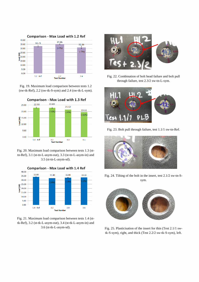
Fig. 19. Maximum load comparison between tests 1.2
(sw-tk-Ref), 2.2 (sw-tk-S-sym) and 2.4 (sw-tk-L-sym).
Fig. 20. Maximum load comparison between tests 1.3 (st-
tn-Ref), 3.1 (st-tn-L-asym-out), 3.3 (st-tn-L-asym-in) and
3.5 (st-tn-L-asym-sd).
Fig. 21. Maximum load comparison between tests 1.4 (st-
tk-Ref), 3.2 (st-tk-L-asym-out), 3.4 (st-tk-L-asym-in) and
3.6 (st-tk-L-asym-sd).
Fig. 22. Combination of bolt head failure and bolt pull
through failure, test 2.3/2 sw-tn-L-sym.
Fig. 23. Bolt pull through failure, test 1.1/1 sw-tn-Ref.
Fig. 24. Tilting of the bolt in the insert, test 2.1/2 sw-tn-S-
sym.
Fig. 25. Plasticisation of the insert for thin (Test 2.1/1 sw-
tk-S-sym), right, and thick (Test 2.2/2 sw-tk-S-sym), left.

Fig. 26. Surface damage due to the contact with the insert
(Hole 1) and cracks in the direction of the fibres (Hole 2),
test 2.3/2 sw-tn-L-sym.
(a)
(b)
(c)
(d)
Fig. 27. Difference in the extension of bearing damage for
thin and thick composite plates from the same joint
configuration. (a) test 2.3/2 sw-tn-L-sym Plate A, (b) test
2.4/2 Plate A sw-tk-L-sym, (c) test 2.3/2 Plate B, (d) test
2.4/2 Plate B.
Fig. 28. Comparison between experimental and numerical
Load-Displacement curves, test 1.3 st-tn-Ref.
Fig. 29. X-Rays applied on Plate A from test 1.1/1 sw-tn-
Ref.
Hole 1 Hole 2


![Improvement of Interfacial Shear Strength Using ...confsys.encs.concordia.ca/ICCM19/AllPapers/FinalVersion/RUT80577.pdf · modified by introducing nano, ... the IFSS [15] and, based](https://static.fdocuments.net/doc/165x107/5abd66f07f8b9a8e3f8bba70/improvement-of-interfacial-shear-strength-using-by-introducing-nano-the.jpg)


