Numbers and Symbols - jangoonow.com Template Guide.docx · Web view4 digit number: Loop code –...
57
Marine Engineer’s Drawing Template Symbols Guide/ Work Reference Design and Marketing by: JangooNow 1001 26 th Street NW, Suite 504; Washington, DC, 20037-1603
Transcript of Numbers and Symbols - jangoonow.com Template Guide.docx · Web view4 digit number: Loop code –...

Marine Engineer’s Drawing Template Symbols Guide/ Work Reference
Design and Marketing by:JangooNow1001 26th Street NW, Suite 504; Washington, DC, 20037-1603

Symbols Guide and Template © 2013, Northern Express Company of Washington, DC.
Copyright Note: the replication of this template into another material, including electronic form, using intellectual property found on the template or this guide, is restricted by Copyright Law. The dissemination of replications of this template to other parties, asides from small portions, for profit or not, is against the Copyright Law.
Please address all correspondence through:
JangooNow1001 26th Street NW, Suite 504; Washington, DC, 20037-1603
Prototypes manufactured by: Pololu, Incwww.pololu.com+1 (702)-262-6648
Production manufactured by:Smith Drafting Company5679 S. Transit Rd., Suite 335Lockport, NY, 14094www.smithdrafting.com+1 (705)-326-9205
The Template and the Symbols Guide were designed and produced in the U.S.A
Proudly Made in America
Table of Contents
4…Why Use this Template?5…The Logical Layout of the Template6…How to Draw Using this Template7…Components of this Template9…Aspects of Mechanical Drawing
11…P&ID Standard Symbols18…Flow Elements19…Line Fittings21…Electrical23…Traps/ Valves26…Functional Elements/Heat Exchangers/Pumps27…Flowchart28…Bell Book Markings/ Chart Plotting Symbols29…Abbreviations
32…Individual Project Management Tips 34…Conversion Tables38…Useful Equations39… Safety Tips, Risk Assessment, Hazard Identification43… Valve Reference Sketches44… Sources and Additional References
Precision Notice: Designer’s guaranteed precision for this template is +/- .06 inch on all lines. For shapes with a given measurement, a tolerance of 1/32 inch is given for kerf (space lost) when using a mechanical pencil. For a drawing that requires high-precision work (such as patterns for laser cutting machines), we recommend the use of a computer-based drawing program. A bevel of up to 2.5 degrees may be present within shapes featured in the template as a result of the manufacturing process.

Why Use this Template?
While on his sea year, Atticus Sawatzki wanted to do a swell job on the drawings for his sea project. Although some of his fellow classmates had bought engineering templates that contained just a few of the symbols that were needed for the drawings, Atticus was not satisfied. After making an OK grade on his drawings, and while serving time on restriction, he came up with an idea. Perhaps, he could order a ‘custom’ template that could be used by his fellow classmates on their next sailing period, and by years of students to come.
Although, at this point in his career, he had just one course in project management, he took matters into his own hands. It would not be a difficult task to make a template, but it would take trial-and-error to create a product that his classmates would actually like to use.
So Atticus ordered several prototypes, and gave them to his fellow classmates to use on their sea projects. Some went to students on the Honor Roll, and others to the average students.When classes reconvened after the sea period, he took a survey of students to get feedback on the product: which new features they would like to see on the template, and, importantly, how the template could be modified to work ergonomically—that is, naturally—for the template’s user. These prototype templates sailed around the work, were exposed to the elements of shipboard life, and had made it back in good condition.
With the feedback, a final design was made and a production run of final template was ordered. Packaging was designed to allow the item to be sold at the ship’s stores of other maritime Academies, and this guide was written to assist users in the use and features of this template.

The Logical Layout of the Template
To our knowledge, this template—designed especially for Marine Engineers and shipboard cadets--- is the first product in its class. And if there were to be a competing template, we are sure that our layout would still be the best.
The layout works best because of ergonomics. The design was made because of the designer’s muscle memory. Before the template came out, the designer spent multiple hours on shipboard systems drawings and realized how a template should be designed for easy use.
Take, for example, the proximity of the arrow guide to the valves. An engineer drawing out a system, based on the designer’s experience, may like to do multiple aspects of the drawing at the same time: the valves, the lines, and the direction of flow. The engineer who uses this template for this purpose will shift the template by just by an inch or so for most of the time required for the drawing.
Ergonomics is not the only benefit of this template. We also designed the template to provide the maximum amount of features, without being cluttered. Why put all we could onto one template? For your convenience and for your wallet. Our template for Marine Engineers may supplant, for you, three other templates you would have otherwise bought. Different users may desire to use only a few of the features on the template; and a point was made to have a clean visual aspect to the template.
How to Draw Using this Template
Positioning of the template in relation to the paper is key to a good result. Ensure that the edge of the template is parallel or flush with the side of the paper; or at the appropriate angle offset if working on an isometric-type drawing.
Hold the template while you draw components, so that it does not slip while you do your work. How you hold your writing utensil is your choice; however, a 30 degree angle towards the edge of the cutout you are drawing from should give you a steady outcome that does not deviate from the shape of the cutout.
The rest is up to you!
Care of your template: Common sense will dictate good practice for the long-term preservation of your template, but here are some tips:
Avoid storage in direct sunlight, or excessively high heat.Avoid excessive bending of the template.
Note for isometric drawings: Using this template at an angle of 30 or 45 degrees will produce a “cabinet” type projection, where the components you draw form the template are shown in a non-isometric scale. It is not possible to use the template for a true “cavalier” type projection.

Components of this Template
This template was designed with you in mind. We would like for you to know how to use our template with maximum effectiveness and efficiency.
The template is divided into sections by engraved lines. In each section, you will find the necessary outlines to draw symbols used in ships’ drawings. The sections are named as followed:
WeldingDimensionsFilters/StrainersNozzlesHeat ExchangersPumps
ElectricalFloorplanVentsAs-built PipingValvesLogic
Rulers are located on three of the edges: Inch, divided into 1/8” increments; Centimeter, divided into ½ cm increments; and 1/10 Inches. In addition, the upper left part of the template is dedicated to general shapes, and the lower left part is dedicated to text boxes. These were specifically designed for use on USMMA’s ‘Cadet Corps’ paper. Another feature of the template is the 1-inch grid system. Using the dots, you can draw a rectangle or square up to 3” x 4”. The upper-left dot is marked with an “x”, and is located in the Filters/Strainers section. The lower-right dot is market with an “x”, and is located near the lower right corner of the template.For drawing at an angle (Isometric), line up the template using the quarter-compass rose in the Dimensions section of the template.


Aspects of Mechanical Drawing
The goal of the mechanical drafter (you) is to provide a clear communication of an idea. In other words, you are drawing something that is worth a thousand or more words.
You may be tied to a scale drawing or floor plan. If you are not, the power is in your hands to draw components with a mind towards visual clarity. Two key points to achieve this goal are listed below:
Flow
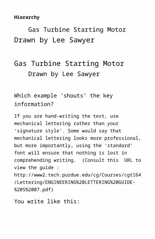
Hierarchy
Gas Turbine Starting MotorDrawn by Lee Sawyer
Gas Turbine Starting MotorDrawn by Lee Sawyer
Which example ‘shouts’ the key information?
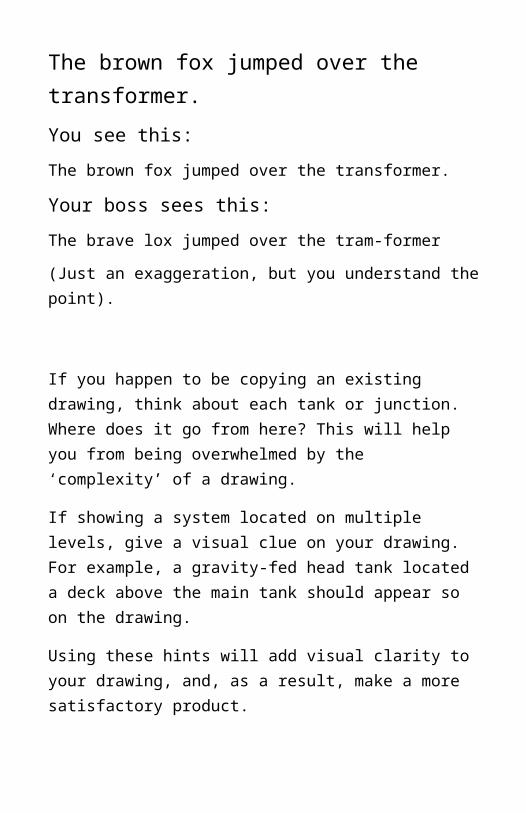
If you are hand-writing the text, use mechanical lettering rather than your ‘signature style’. Some would say that mechanical lettering looks more professional, but more importantly, using the ‘standard’ font will ensure that nothing is lost in comprehending writing. (Consult this URL to view the guide : http://www2.tech.purdue.edu/cg/Courses/cgt164/Lettering/ENGINEERING%20LETTERING%20GUIDE-%20S%2007.pdf)
You write like this:
The brown fox jumped over the transformer. You see this:The brown fox jumped over the transformer. Your boss sees this:
The brave lox jumped over the tram-former
(Just an exaggeration, but you understand the point).
If you happen to be copying an existing drawing, think about each tank or junction. Where does it go from here? This will help you from being overwhelmed by the ‘complexity’ of a drawing.
If showing a system located on multiple levels, give a visual clue on your drawing. For example, a gravity-fed head tank located a deck above the main tank should appear so on the drawing.
Using these hints will add visual clarity to your drawing, and, as a result, make a more satisfactory product.

Piping and Instrumentation Diagram (P&ID) Symbols
On ships’ drawings, there are generally two methodologies of P&ID. Electricians and electrical engineers use diagrams where components are labeled with geometric shapes. Operating engineers (and Cadets) will prefer to simplify mechanical/digital logic components marked on their drawings into rectangular boxes—with a few exceptions.
Left: An Electrical Engineer’s symbol for a Volume Indicator and Transmitter
Labeling P&ID Symbols
1st Letter: Variable being measured (Pressure, Temperature, etc.). Some variables or modifiers, such as “Differential”, provide a second letter, as in DP for differential pressure. Consult ISA 5.1 standard for full list of codes.
2nd / 3rd Letter: Indication functionality (‘I’ stands for Indicating)—optional
Final Letter: Output functionality (‘T’ stands for Transmitter)--- optional
(Example: a temperature meter that transmits but not indicate would be labeled: TT)

4 digit number: Loop code – optional—refer to specification/ lead sheet provided with drawing for description, reference, or explanation. Usually refers to the system this P&ID is attached to.
Above: Marine Engineers often use this symbology for P&ID symbols. “Loop Numbers” are rarely used on piping diagrams.
Common codes for 1st letter:
A- Analyzer L- Level T- Temperature
P- Pressure V- Vacuum F- Flow
Common 2-letter Codes:
CI- Compound Indicator
SC- Speed Control HS- Hand Switch
XV- Actuated Valve SV- Solenoid Valve
ZS- Limit Switch PS- Pressure Switch
FI- Flow Indicator TS- Temperature Switch
VS- Vibration Switch (_)S- Switch
(_)I- Indicator (_)T or (_)X- Transmitter
(_)C- Controller (_)R- Recorder
Common 3-letter Codes:
LLA- Low Level Alarm (or LAL)
HLA- High Level Alarm (or LAH)
Also for Low/High Temperature or Pressure.
TLI- Tank Level Indicator
FLS- Float Switch
ASP- Automatic Stop
AST- Automatic Start
APG- Air Purge Gauge
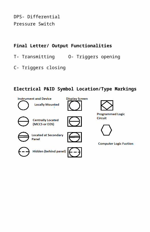
DPS- Differential Pressure Switch
Final Letter/ Output Functionalities
T- Transmitting O- Triggers opening
C- Triggers closing
Electrical P&ID Symbol Location/Type Markings

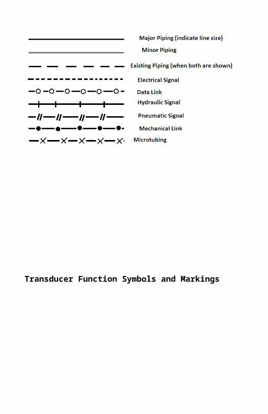
Transducer Function Symbols and Markings
Transducer Markings
Transducers are marked by this symbol on electrical diagrams (Top Left).
Signal actuators use this symbol, but use the same markings as transducers (Bottom Left).
I/ I - Current to Current
I/ P- Current to Pneumatic
I/ E- Current to Voltage
P/ I- Pneumatic to Current
P/E- Pneumatic to Voltage
E/ I- Voltage to Current
E/ P- Voltage to Pneumatic
E/ E- Voltage to Voltage

Example:
From Left to Right:
Left: A hydraulic line feeds an H/P Actuator, which activates a piston to operate the controlled valve.
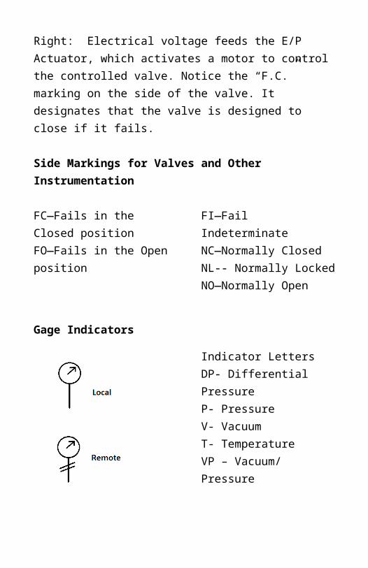
Center: An electrical current feeds the I/P Actuator, which activates the diaphragm valve. Right: Electrical voltage feeds the E/P Actuator, which activates a motor to control the controlled valve. Notice the “F.C.” marking on the side of the valve. It designates that the valve is designed to close if it fails.
Side Markings for Valves and Other Instrumentation
FC—Fails in the Closed positionFO—Fails in the Open position
FI—Fail IndeterminateNC—Normally ClosedNL-- Normally LockedNO—Normally Open

Gage Indicators
Indicator LettersDP- Differential PressureP- PressureV- VacuumT- TemperatureVP – Vacuum/ Pressure
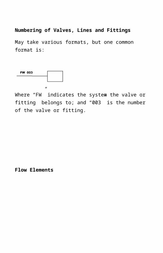
Numbering of Valves, Lines and Fittings
May take various formats, but one common format is:
Where “FW” indicates the system the valve or fitting belongs to; and “003” is the number of the valve or fitting.
Flow Elements
Line Fittings
Line Fittings

Electrical Symbols

Electrical Symbols
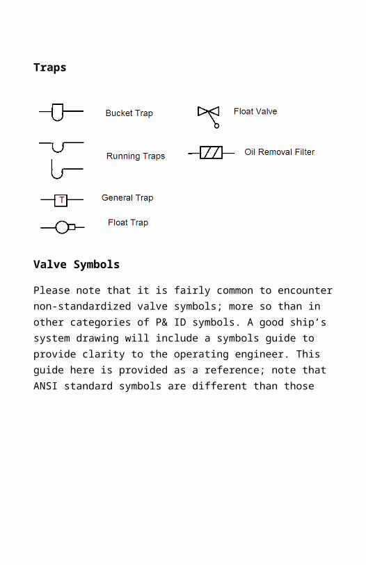
Traps
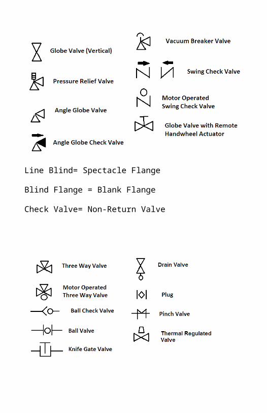
Valve Symbols
Please note that it is fairly common to encounter non-standardized valve symbols; more so than in other categories of P& ID symbols. A good ship’s system drawing will include a symbols guide to provide clarity to the operating engineer. This guide here is provided as a reference; note that ANSI standard symbols are different than those listed here.

Line Blind= Spectacle Flange
Blind Flange = Blank Flange
Check Valve= Non-Return Valve


Functional Elements/ Heat Exchangers
Pumps

Flowchart Symbols

Standard Bell Book Symbols
Chart Plotting Symbols
Track Line
Abbreviations Used in Marine Drawings
A/B – Above Baseline
A.C.C.- Automatic Combustion Control
A/E- Auxiliary Engine
Arr’t- Arrangement
Auto.- Automatic
BHD- Bulkhead
BHP- Brake Horsepower
BLR- Boiler
BWL- Ballast Water Line
Cap.- Capacity
C/D- Cofferdam
Cent.- Centrifugal
Circ.- Circulating
Cond.- Condensate
CLR- Cooler
Ctr. – Counter, or Center
C/S- Camshaft
D/G- Diesel Generator
Dk.- Deck
DRN- Drain
DWG- Drawing
ECR- Engine Control Room
EOS- Enclosed Operating Station
E/R- Engine Room
ERW- Electric Resistance Welded Pipe
FR- Frame
F.A.- Free Air
Fwd.- Forward
FD- Feed
Galv.- Galvanized
G/E- Generator Engine
Gen.- Generator, or General
G/T or GTRB- Gas Turbine
HFO- Heavy Fuel Oil
HTR- heater
Hyd.- Hydraulic
L.C.V.- Lower Calorific Value

LFFS- Local Firefighting Station
L.W.L.- Low Water Line
IFO- Intermediate Fuel Oil
MCR- Maximum Continuous Rating
MDO- Marine Diesel Oil
M/E- Main Engine
M/H- Manhole
M/T- Marine Tanker, or Empty
MTH- Total Head, Meters
N.A.- Non-Asbestos
NCR- Normal Continuous Rating
N.D.- Nominal Diameter
P/P- Pump
QC- Quick Closing
QTY- Quantity
R/G- Reduction Gear
Ref.- Refrigeration or Reference
Rm.- Room
S.B.- Stuffing Box
S.C.- Sea Chest
SC- Cast Steel
S/G- Specific Gravity
SP- Sounding Pipe
Spec.- Specification
S/S- Ship Side
S/T- Stern Tube
S&T- Shell and Tube
STBD- Starboard
STBY- Standby
STM- Steam
STRG- Steering
S/G- Steering Gear
S.W.- Seawater, Saltwater, or Socket Weld
SWL- Safe Working Load, or Summer Water Line
SWRM- Mild Steel Wire Load
Stl- Steel
SMLS- Seamless
T/C- Turbocharger
Thck.- Thickness
Thru- Through
Tk- Tank
Vlv. Or V/V- Valve
WO- Waste Oil
Note: Additional abbreviations can be created by using the first syllable of the piece of machinery or concept, giving at least 3 letters. Example: TYP for Typical.

Individual Project Management Tips
There are fundamental project management tips that are applicable to projects of all sizes, small to large. A number of the principles that apply to managing a large project are applicable to projects of a smaller scale (though they too may take up a large part of your time!) It’s also good to keep in mind that as your career progresses, you’ll be working on larger projects and assuming greater responsibility for the successful, on-time completion of the project at hand.
Know the details of the project
Understand the expectations of the stakeholders and shareholders.
Know the scope of the project
Establish a criteria for tracking progress. Ensure compliance with specifications and regulations. Consider the following steps of a project when writing a plan: Planning, Execution, Closure.
Practice leadership principles
Even if you are the sole proprietor of the project, assume a leader’s role in motivating yourself to give your best to the project.
Plan for the resources you will need
This includes supplies, reference books, and people with the know-how who can help you out. Keep lines of communication open with the stakeholders in case a situation does arise.

Reduce risks
Examples of risks include unforeseen circumstances that cause delays in your ability to complete the project. Plan for this by starting early!
Keep the big picture in mind
When under the crucible of time, you understand how every minute matters. Apply the same principle to time management when the deadline seems far away. Also, make sure you don’t get too focused with details when there is a lot of meat work left to do.
Evaluate the project
Before the deadline, ask yourself: “Is this what I want as a finished product? Is this what the stakeholder wants as a finished product?” After closing out the project, give yourself an honest evaluation. Consider the successes and the disappointments of the project, and keep these in mind for the future.
(Derived from Villanova University Project Management Tips).

Conversion Tables
Numbers and Symbols
For small integers without units, write out the word:“Seven trials were performed…”
Otherwise, use numbers.
Leave a space or use comma between groups of three digits10, 000
Or use scientific notation10^4
Keep in mind significant figures!5.35 / 3.24 = 1.65, NOT 1.651234568
Rounding vs. TruncationTruncation is dropping figures after a certain digit without
rounding.
Standard UnitsUnit/System SI CGS British
EngineeringLength Meter (m) Centimeter (cm) Foot (ft)Mass kilogram (kg) gram (g) SlugTime (s) second (s) second (s) second Force (lb) Newton (N) dyne pound
Equivalent Conversions QuantityAmerican unit Equivalent SI units
Length 1 yd 0.9144 m 1 ft 0.1048 m
1 in 0.0254 in

1 mile 1609.344 m1 nautical mile 1852 m
Area 1 in2 645.16 x 10⁻⁶ m2
1 ft2 0.092903 m2
1 yd2 0.836127 m2
1 mile2 2.58999 X 10⁶ m2
Volume 1 in3 16.3871 X 10⁻⁶ m3
1 ft3 0.0283168 m3
1 gal 0.004546092 m3
Velocity 1 ft/s 0.3048 m/s1 mile/hr 0.44704 m/s; 1.60934 km/hr1 knot 0.51444 m/s; 1.952 km/hr
Standard acceleration. g 32.174 ft/s2; 9.80665 m/s2
Mass 1 lb 0.45359237 kg1 ton 1016.05 kg
Mass density 1 lb/in3 27.6790 x 10³ kg/m3
1 lb/ft3 16.0185 kg/m3
Force 1 pdl 0.1 38255 N1 lbf 4.44922 N
Pressure 1 lb/in2 6894.76 N/m2
1 tonr/in2 15.4443 x10⁶ N/m2
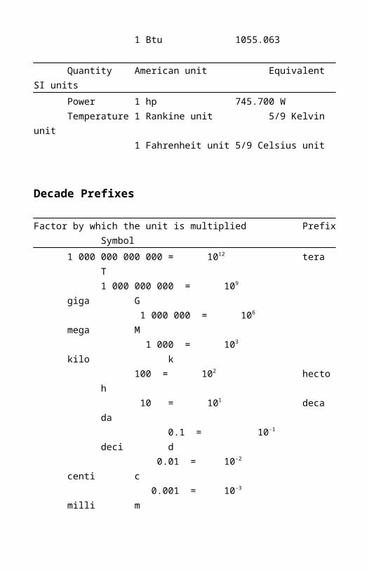
Energy 1 ft pdl 0.0421401 J1 ft lbf 1.35582 J1 cal 4.1868 J1 Btu 1055.063
QuantityAmerican unit Equivalent SI unitsPower 1 hp 745.700 WTemperature 1 Rankine unit 5/9 Kelvin unit
1 Fahrenheit unit 5/9 Celsius unit

Decade Prefixes
Factor by which the unit is multiplied Prefix Symbol1 000 000 000 000 = 1012 teraT 1 000 000 000 = 109 gigaG 1 000 000 = 106 megaM
1 000 = 103 kilo k
100 = 102 hectoh
10 = 101 decada
0.1 = 10-1 decid
0.01 = 10-2 centic
0.001 = 10-3 millim
0.000001 = 10-6 micro
Marine Engineering Abbreviations (Scientific)
air horsepower air hp inch-pound in-lbaverage avg indicated horsepower ihpBrake horsepower bhp kilogram kgBritish thermal unit Btu or B kilowatt kWcentimeter cm kilowatt hour kWhcubic cu latitude latcubic foot cu ft logarithm logcubic foot per minute cfm logarithm (natural) lncubic foot per second cfs mean effective pressure mepcubic in cu in millivolt mV

Degree (angular measure) deg or minute mindegree centigrade C mole moledegree Fahrenheit F ohm ohmdegree Kelvin K ounce ozelectromotive force emf pound or pounds lbfeet per minute fpm pound-foot lb-ftfeet per second ft/2 pounds per brakefoot or feet ft horsepower-hour lb per bhp-hr
Marine Engineering Abbreviations (Scientific), Continuedfoot-pounds ft-lbs pounds per cubic foot lb per cu ftfrequency f pounds per square foot psfgallon gal pounds per square inch psigallons per minute gpm pounds per square inchgallons per second gps absolute psia
pounds per square inch gagepsig
horsepower hp revolutions per minute rpmhorsepower-hour hp-hr shaft horse power shphour hr specific heat sphtinch in square foot sq ft
square in sq involt Vwatt Wwatthour Wh
Sources: Guide to Engineering Reports, USMMA, John Tuttle, 2006; Design Data and Calculations, Data Item Description DI-GDRQ-80650, Department of Defense

Equations
Engine
W =P∗L∗A∗N
Pump Head
Electrical
V=IR
P=I 2 R
V= Voltage; volts (V)I = Current; amps (A)R = Resistance; ohms (Ω)P= Power; watts (W)L= Inductance; Henries (h)

Safety Tips
In the Engine Room:
Enclosed Spaces and Tanks: Follow proper checklist procedures prior to entry. Taking shortcuts may end very badly. At a minimum, you need to carry out gas-free procedures, ensure adequate oxygen, carry a flashlight, and have a spotter at the entrance to the enclosed space.
Tank Rescue: Don’t let the same thing that knocked out your co-worker knock you out too! If a person needs to be removed from an enclosed space, it is likely due to a bad atmosphere inside the space. What you need to do is notify the bridge, and only enter with proper gear—that is, an SCBA. Using an EEBD to perform a rescue does not protect you from toxic gases.
Hot Work: Follow proper checklist procedures prior to performing work to prevent the risk of fire.
Deadly Gases:
There are several deadly gases you should be especially aware of, and how you could be dangerously exposed to them:
CO2: Carbon Dioxide, a common fire suppressant agent.
CO: Carbon Monoxide, the product of incomplete combustion.
H 2 S: Hydrogen Sulfide, a byproduct of the mixing of saltwater and organic matter. Can be produced in the MSD.
Benzene: Comes from fuel products and their vapors, including bunkers on any type of ship. Use proper PPE. Note that exposure to excessive amounts of benzene can disqualify you from working on a ship.
Good to know: Report injuries and illnesses to the medical officer as soon as possible. This is important for workman’s injury compensation, and for your health. If your condition gets worse while far from shore, tough luck. “Acting man” today can cost you tomorrow.
What to Wear and Carry on the Job
- Coverall or work pants/ jeans and Steel Toed Shoes- Work Gloves and rag- Rubber Gloves- Watch with second hand- Notepad, pen, pencil and sharpie marker- Small Crescent Wrench (that won’t fall out of your pocket)- Safety Glasses (it’s more than regular glasses…)- Earplugs (include a spare pair)- Optional: Hard Hat and Long Sleeves

Risk Assessment
Part of your SMS—Safety Management System
What is acceptable risk?Chance of Occurrence ---- Severity of an OccurrenceValue
Chance of Occurrence Severity of an Occurrence
5 Likely Death or Serious Injury; damaging financial or public relations cost
4 Significant (1 incident in 100 tasks)
Hospitalization, major costs
3 Moderate Lost-Time Injury, notable costs
2 Possible Minor Injury, costs involved1 Minimal Negligible
(Note that there is no exact price tag to financial severity; view the financial aspect in ‘relative’ terms to your organization’s situation).
Adding the value of the chance of occurrence and the severity of occurrence should total to less than 4.
Do the benefits outweigh the risk?
Yes or No?
What could go wrong?
Example: Slips and Trips
What can be done to reduce the severity of an incident?
Example: Use a safety harness
What can be done to reduce the chance of an occurrence?
Example: Reduce the number of times or duration of a task performed.

Hazard Identification
Potential for dropped objects?
Use of lifting or overhead equipment?
Working under suspended load?
Manual handling of heavy objects?
Working in a confined space?
Working aloft?
Risk of slips, trips, and falls?
Working on or near high voltage
Working on pressurized or stored energy systems?
Working with or around dangerous or biohazard materials?
Poor visibility?
New or unfamiliar personnel?
Potential of damage to equipment or environment?
Working with rotating or pinching equipment?
Using vibrating machinery that is hard to handle?
(Source: OSG, Inc. Safety Flashcard)

Valve Identification Sketches
Butterfly Valve
Gate Valve
Globe Valve
Angle Valve
Check Valve

Sources and Additional References
Sources:
Microsoft Word 2010, Flowchart Symbols.
Design Data and Calculations, Data Item Description DI-GDRQ-80650, Department of Defense
Guide to Engineering Reports, USMMA, John Tuttle, 2006
http://www.villanovau.com/project-management-tips/
Rapidesign, R-40 Circles Template. Order: www.chartpak.com
Timely Templates, Flowplan Template No. T-59. Order: www.timelytemplates.com
URLs to Additional References for the Marine Engineer:
Mechanical Lettering Guide for Engineers
http://www2.tech.purdue.edu/cg/Courses/cgt164/Lettering/ENGINEERING%20LETTERING%20GUIDE-%20S%2007.pdf
Essentials of Lettering (Thomas E. French, 1912)
http://www.kellscraft.com/EssentialsofLettering/EssentialsofLetteringContentPage.html
Interpreting P&ID Symbolics
http://chenected.aiche.org/plant-operations/interpreting-piping-and-instrumentation-diagrams-symbology-part-3-of-5/
Notes